Embed Size (px)
Citation preview
8/3/2019 Tde Final Report
http://slidepdf.com/reader/full/tde-final-report 1/37
Cellular Mobile Radio Base Station Network Planning for
Telecommunications
1 INTRODUCTION
This project is based on the designing of a cellular network for a real
geographical area on the software named Cell Planner. Cell Planner is the
software which provides all the functions for the design of a wireless
system and allows us to estimate the performance of the designed system
or we can say wireless system. It is essentially helpful for almost all the
frequency ranges for Analog, TDMA, CDMA, GSM and 3G. Our project is
based on the designing of GSM Public Land Mobile Network (PLMN). It is a
very supportive tool through which we can actually see the characteristic
of a particular base station under different circumstances including its
antenna, power, height and other parameters.
The project teaches us the technical concepts of a cellular network and
also provides us the understanding of terms such as co channel
interference, adjacent channel interference and composite interference.
Also we came to know how an antenna will behave in different situationsand how its pattern gets affected by the environment
1.1 Purpose
The purpose of the project is to understand the concepts of the cellular
network deeply and to learn how to tackle with the different problems
which a Base station Engineer face while installing a base station and also
what all things should be kept in mind before performing such action. As
the main aim of a Base station Engineer is to work for his desired task
efficiently and perform all the actions involved in it considering the
economic as well as the technical aspects, moreover network should
satisfy the quality of service (QoS).
1.2 Scope
1 | P a g e
8/3/2019 Tde Final Report
http://slidepdf.com/reader/full/tde-final-report 2/37
Cellular Mobile Radio Base Station Network Planning for
Telecommunications
The Scope of this project includes the entire technical requirement for the
network which we can use efficiently. It provides the. Also this project
enables an engineer to create a network using all the requirements given.
It comprises of planning, designing, simulating and analysing the designed
cellular network
1.3 Report Organisation
The main aim of this project is to achieve a good coverage in a particular
area with the best possible way including the cost and maintenance of the
network. This Report presented is organised in three different sections
which are:
Network configuration including Base Station Sites.
Antenna selection criterion and assigning frequency.
Good Coverage with handling traffic easily.
2 NETWORK PLANNING APPROACH
This part of the project may be treated as the main part as planning a
network means to create the back bone of a human. If the back bone isweak then the whole system will suffer, causing the network to degrade its
performance which is not acceptable. As it has been said again and again
that for a cellular network two things are the most vital elements are
Coverage and traffic. If these two things are good enough to achieve
desired GoS then the task is accomplished. Thus the approach towards the
designing of the project should be firm and fixed in order to achieve the
task successfully.
2 | P a g e
8/3/2019 Tde Final Report
http://slidepdf.com/reader/full/tde-final-report 3/37
Cellular Mobile Radio Base Station Network Planning for
Telecommunications
1.4 General Requirements:
The first thing which comes in mind before planning a network is “How to
build a cellular mobile telecommunication network for a given area
effectively and efficiently?” The answer to this will be, use all the
resources efficiently and for this the basic requirements of our project
include the antenna selection, area to covered, base station parameters
such as power, height, cell radius and frequency.
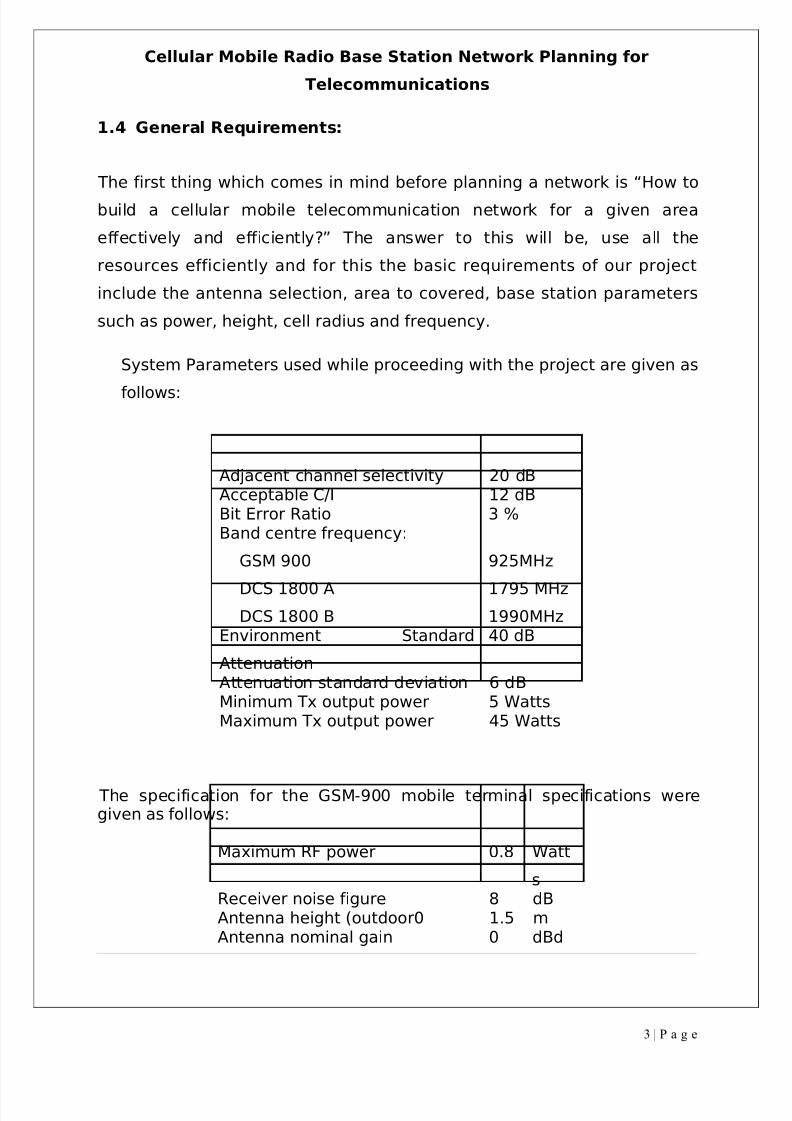
System Parameters used while proceeding with the project are given as
follows:
Adjacent channel selectivity 20 dBAcceptable C/I 12 dBBit Error Ratio 3 %Band centre frequency:
GSM 900
DCS 1800 A
DCS 1800 B
925MHz
1795 MHz
1990MHzEnvironment Standard
Attenuation
40 dB
Attenuation standard deviation 6 dBMinimum Tx output power 5 WattsMaximum Tx output power 45 Watts
The specification for the GSM-900 mobile terminal specifications weregiven as follows:
Maximum RF power 0.8 Watt
sReceiver noise figure 8 dBAntenna height (outdoor0 1.5 mAntenna nominal gain 0 dBd
3 | P a g e
8/3/2019 Tde Final Report
http://slidepdf.com/reader/full/tde-final-report 4/37
Cellular Mobile Radio Base Station Network Planning for
Telecommunications
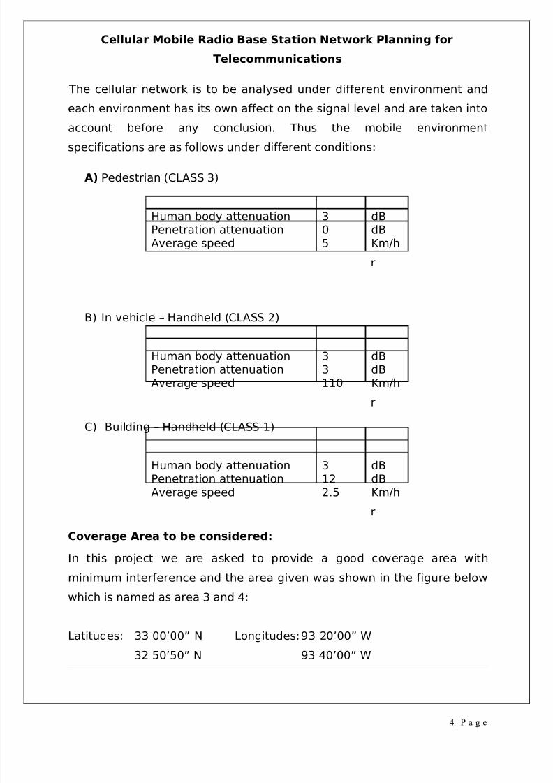
The cellular network is to be analysed under different environment and
each environment has its own affect on the signal level and are taken into
account before any conclusion. Thus the mobile environment
specifications are as follows under different conditions:
A) Pedestrian (CLASS 3)
Human body attenuation 3 dBPenetration attenuation 0 dBAverage speed 5 Km/h
r
B) In vehicle – Handheld (CLASS 2)
Human body attenuation 3 dBPenetration attenuation 3 dBAverage speed 110 Km/h
r
C) Building – Handheld (CLASS 1)
Human body attenuation 3 dBPenetration attenuation 12 dBAverage speed 2.5 Km/h
r
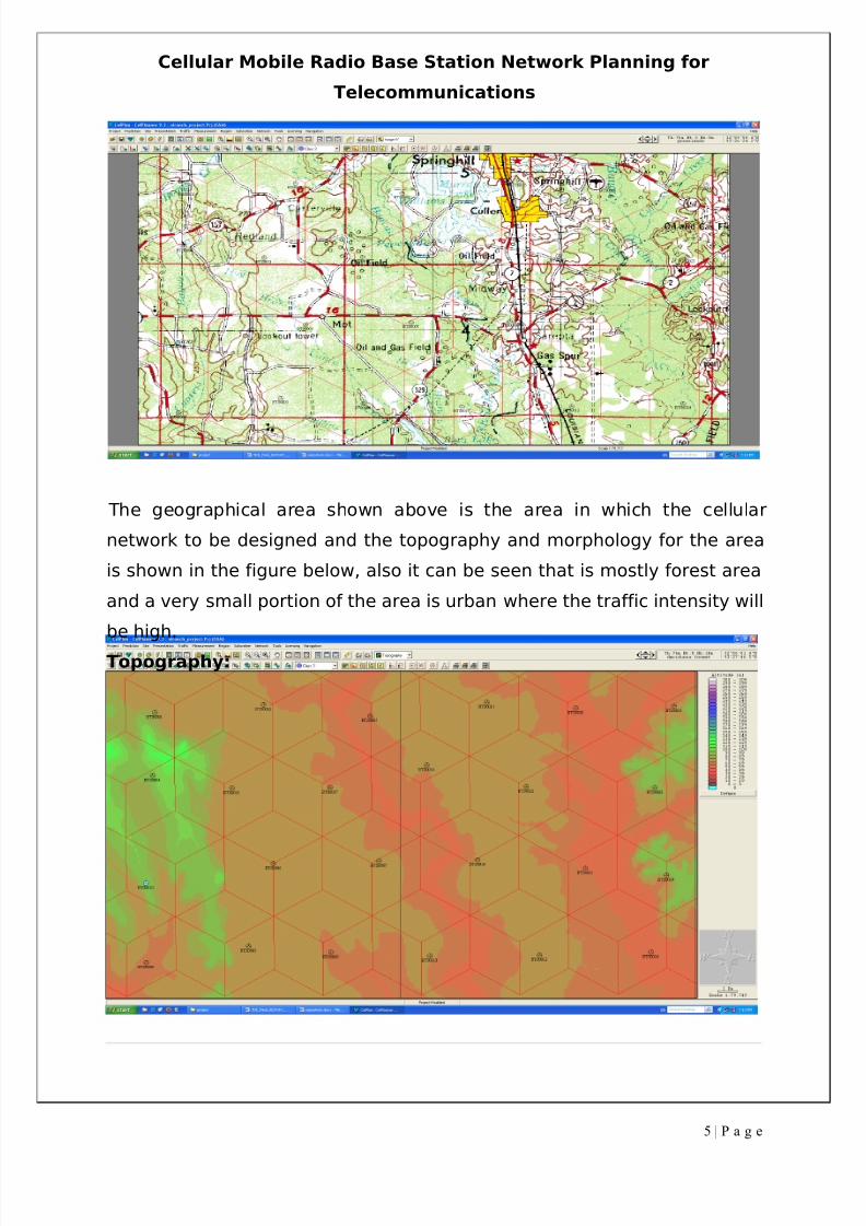
Coverage Area to be considered:
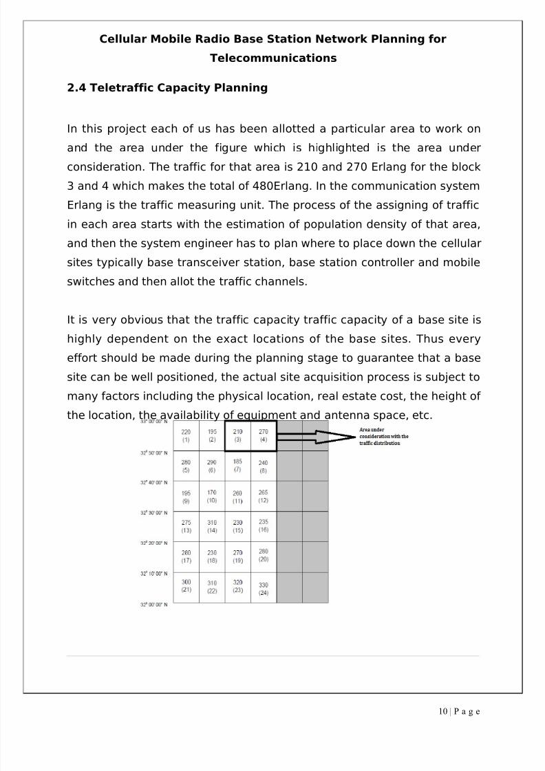
In this project we are asked to provide a good coverage area with
minimum interference and the area given was shown in the figure below
which is named as area 3 and 4:
Latitudes: 33 00’00” N Longitudes:93 20’00” W
32 50’50” N 93 40’00” W
4 | P a g e
8/3/2019 Tde Final Report
http://slidepdf.com/reader/full/tde-final-report 5/37
Cellular Mobile Radio Base Station Network Planning for
Telecommunications
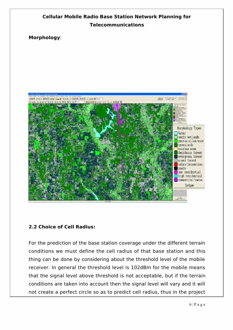
The geographical area shown above is the area in which the cellular
network to be designed and the topography and morphology for the area
is shown in the figure below, also it can be seen that is mostly forest area
and a very small portion of the area is urban where the traffic intensity will
be high.
Topography:
5 | P a g e
8/3/2019 Tde Final Report
http://slidepdf.com/reader/full/tde-final-report 6/37
Cellular Mobile Radio Base Station Network Planning for
Telecommunications
Morphology:
2.2 Choice of Cell Radius:
For the prediction of the base station coverage under the different terrain
conditions we must define the cell radius of that base station and this
thing can be done by considering about the threshold level of the mobile
receiver. In general the threshold level is 102dBm for the mobile means
that the signal level above threshold is not acceptable, but if the terrain
conditions are taken into account then the signal level will vary and it will
not create a perfect circle so as to predict cell radius, thus in the project
6 | P a g e
8/3/2019 Tde Final Report
http://slidepdf.com/reader/full/tde-final-report 7/37
Cellular Mobile Radio Base Station Network Planning for
Telecommunications
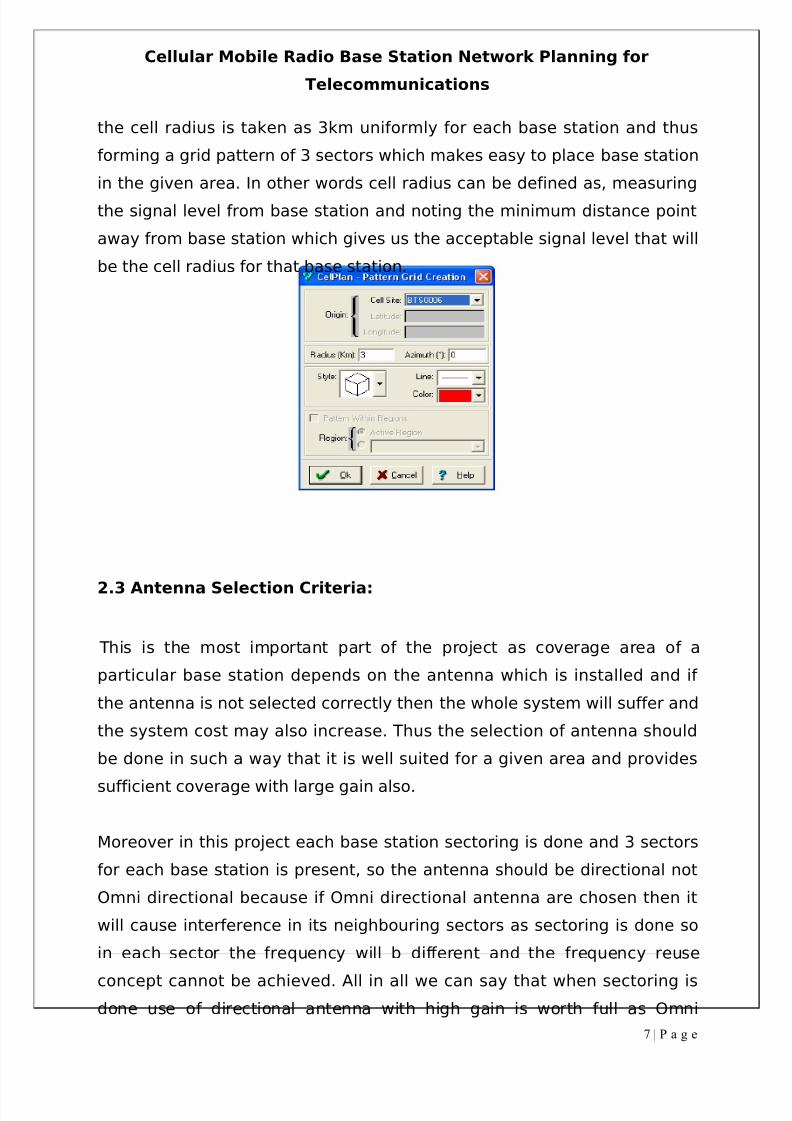
the cell radius is taken as 3km uniformly for each base station and thus
forming a grid pattern of 3 sectors which makes easy to place base station
in the given area. In other words cell radius can be defined as, measuring
the signal level from base station and noting the minimum distance point
away from base station which gives us the acceptable signal level that will
be the cell radius for that base station.
2.3 Antenna Selection Criteria:
This is the most important part of the project as coverage area of a
particular base station depends on the antenna which is installed and if
the antenna is not selected correctly then the whole system will suffer and
the system cost may also increase. Thus the selection of antenna should
be done in such a way that it is well suited for a given area and provides
sufficient coverage with large gain also.
Moreover in this project each base station sectoring is done and 3 sectors
for each base station is present, so the antenna should be directional not
Omni directional because if Omni directional antenna are chosen then it
will cause interference in its neighbouring sectors as sectoring is done so
in each sector the frequency will b different and the frequency reuse
concept cannot be achieved. All in all we can say that when sectoring is
done use of directional antenna with high gain is worth full as Omni
7 | P a g e
8/3/2019 Tde Final Report
http://slidepdf.com/reader/full/tde-final-report 8/37
Cellular Mobile Radio Base Station Network Planning for
Telecommunications
directional antennas are mostly used in rural areas where the traffic
intensity is very less. For designing a cellular system there are several
things which should be kept in mind which area as described below-
Coverage
The first and foremost thing which be kept in mind that where the
antenna is to be placed and how much area it has to cover. Thus an
antenna which can cover large enough area to with all the other
parameters unaffected described below should be chosen and this
thing can be done by analysing the terrain data of that area as the
coverage area of an antenna largely depend on the place where it is
situated.
Interference
After the coverage area is achieved then interference level is to be
checked and if the interference is high then it has to be minimised in
order to provide good service, while minimising the interference
level coverage area must be looked out whether it is affected or not.
The best way to achieve this is to allot frequency to each sector of a
base station properly moreover the antenna specification such as
antenna height, power and tilting should be adjusted so far to
minimise interference
Traffic carrying capacity
The antenna selected should also carry the traffic in that area
effectively and the traffic is distributed according to morphology.
Overall the system can handle traffic easily with less blocking
probability and a good GoS which is 2% in this project.
Gain
Gain of the antenna is directly related to its directivity, the more the
gain of an antenna more directional it will be. While sectoring is
8 | P a g e
8/3/2019 Tde Final Report
http://slidepdf.com/reader/full/tde-final-report 9/37
Cellular Mobile Radio Base Station Network Planning for
Telecommunications
done the antenna should be good enough directional with high gain
so as to provide strongest signal for its sector. And in case if the
antenna is to be tilted to minimise the interference it can be done as
tilting is done only to high gain direction antenna because tilting an
Omni directional antenna is of no use.
Front to back ratio
Front to back ratio of an antenna can be measured by its radiation
pattern and this ratio should be high enough so that it does not
cause interference with other sectors. In other words it is the ratio of
power gain between the front and the rear of a directional antenna.
Null fill
Null is the area present in between the side lobes which means the
area where signal level is nearly equal to zero. These null may be in
order of 30 or more dB which is less than one thousand of the total
energy. Null fill is done to prevent the signal overshooting the
nearest part of the intended coverage area for the antennas located
on mountains or tall towers.
Prone to atmospheric conditions
Antenna structure should be strong enough to handle wind pressure,
rain, storms etc, thus the signal level should not be so much affected
that the system tends to fail.
Cost
Although the base station antenna contribute very less part of the
overall cost of the system, this thing should be kept in mind as in
case of failure the system engineer should have a spare antenna for
its replacement. As we know in a communication system each of its
part has its own importance on the system performance and also the
total cost.
9 | P a g e
8/3/2019 Tde Final Report
http://slidepdf.com/reader/full/tde-final-report 10/37
8/3/2019 Tde Final Report
http://slidepdf.com/reader/full/tde-final-report 11/37
Cellular Mobile Radio Base Station Network Planning for
Telecommunications
There are two ways by which the teletraffic can be carried out easily i.e.
installing another base station near a pre installed site working on
different frequency or to increase the number of traffic channels.
2.5 Grade of Service and Blocking Probability:
For a cellular system the grade of service should be good enough so that
the customers are well satisfied by the service. The grade of service
depends on the call quality which includes voice quality, call drop etc. In
other words the amount of traffic not handled by the network helps to
determine the quality of service. Mathematically it is the ratio of lost traffic
to the offered traffic.
GoS = A-A0/A
Where,
A-actual traffic
A-A0-lost traffic
The blocking probability is the probability of a call not carried out when the
system is busy or the traffic channels are all equipped. This happens due
to traffic overload or lack of traffic channels. When the number of traffic
channels is all busy then the new call originated will be blocked.
3 NETWORK SOLUTION DESCRIPTION
For a cellular network to be designed the main objective of a BTS engineer
is:
To obtain adequate coverage over the entire service area to
ensure that high quality services and data services with less
error rates can be offered to the users.
11 | P a g e
8/3/2019 Tde Final Report
http://slidepdf.com/reader/full/tde-final-report 12/37
Cellular Mobile Radio Base Station Network Planning for
Telecommunications
To offer the subscriber traffic network capacity with
sufficiently low blocking and call dropping rate.
To enable an economical network implementation when the
service is established and a controlled network expansion
during the lifecycle of the network.
For the network operator good network planning is:
Less amount of money utilized for the infrastructure.
More pleased customers (good service quality).
Less need for adjustments.
For an operator network optimization is:
Better return for investment.
Less need for costly hardware updates.
Less need for new sites (which are very expensive).
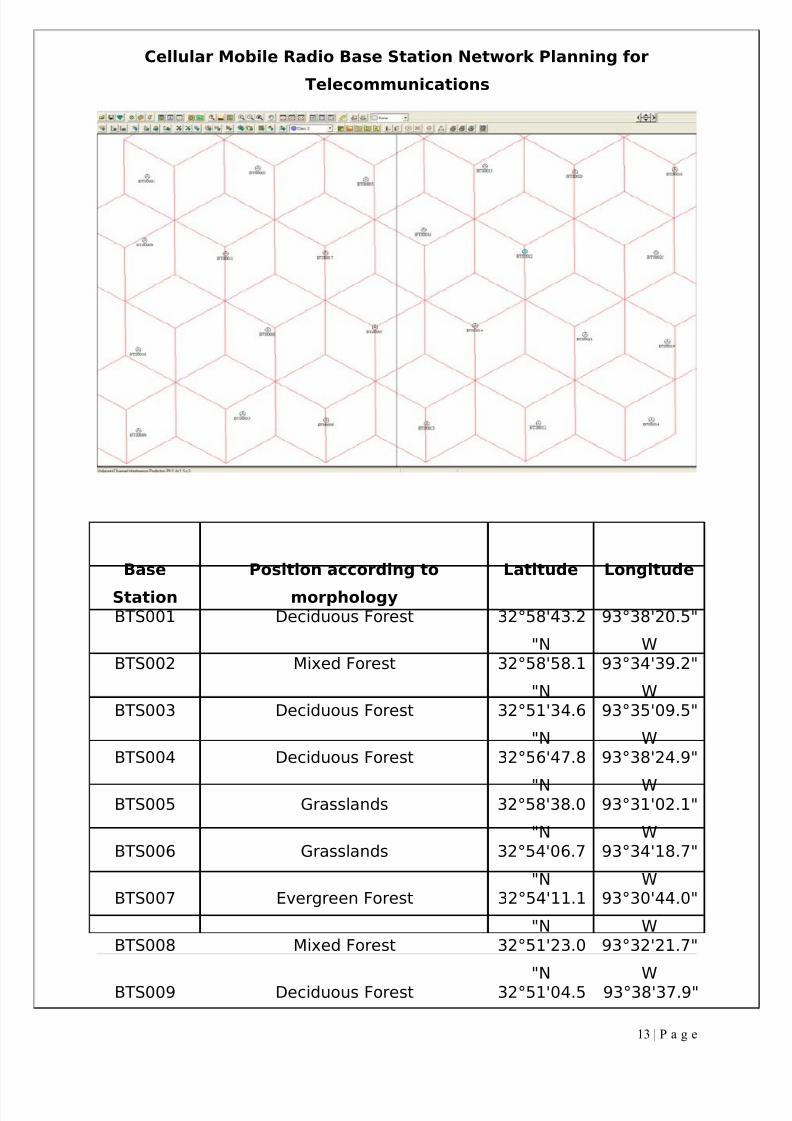
3.1 Network Configuration:
A telecommunication network consists of a base station, antenna, mobile
users, MSC’s, PSTN and microwave links connecting the mobile users with
the stations. The base station in this project which forms a cellular network
are placed as shown in the figure below and the table shows their exact
positions:
12 | P a g e
8/3/2019 Tde Final Report
http://slidepdf.com/reader/full/tde-final-report 13/37
Cellular Mobile Radio Base Station Network Planning for
Telecommunications
Base
Station
Position according to
morphology
Latitude Longitude
BTS001 Deciduous Forest 32°58'43.2
"N
93°38'20.5"
WBTS002 Mixed Forest 32°58'58.1
"N
93°34'39.2"
WBTS003 Deciduous Forest 32°51'34.6
"N
93°35'09.5"
WBTS004 Deciduous Forest 32°56'47.8
"N
93°38'24.9"
WBTS005 Grasslands 32°58'38.0
"N
93°31'02.1"
WBTS006 Grasslands 32°54'06.7
"N
93°34'18.7"
WBTS007 Evergreen Forest 32°54'11.1
"N
93°30'44.0"
WBTS008 Mixed Forest 32°51'23.0
"N
93°32'21.7"
WBTS009 Deciduous Forest 32°51'04.5 93°38'37.9"
13 | P a g e
8/3/2019 Tde Final Report
http://slidepdf.com/reader/full/tde-final-report 14/37
Cellular Mobile Radio Base Station Network Planning for
Telecommunications
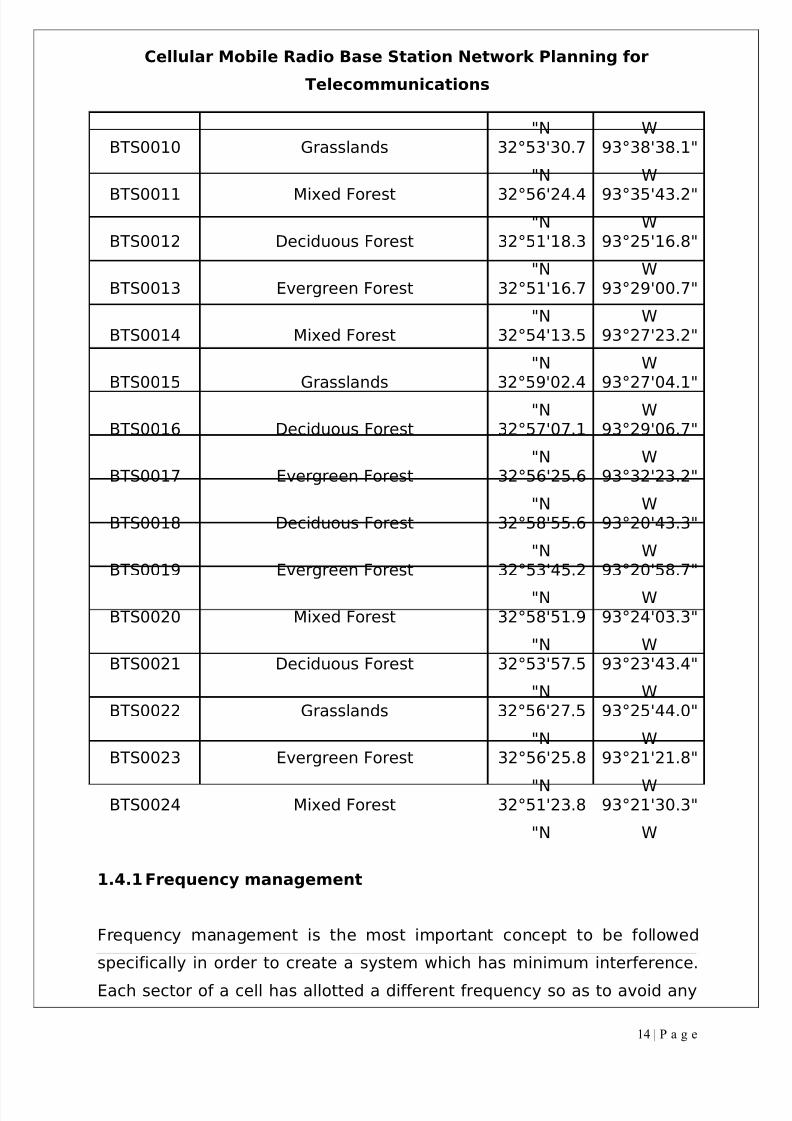
"N WBTS0010 Grasslands 32°53'30.7
"N
93°38'38.1"
W
BTS0011 Mixed Forest 32°56'24.4"N
93°35'43.2"W
BTS0012 Deciduous Forest 32°51'18.3
"N
93°25'16.8"
WBTS0013 Evergreen Forest 32°51'16.7
"N
93°29'00.7"
WBTS0014 Mixed Forest 32°54'13.5
"N
93°27'23.2"
WBTS0015 Grasslands 32°59'02.4
"N
93°27'04.1"
WBTS0016 Deciduous Forest 32°57'07.1
"N
93°29'06.7"
WBTS0017 Evergreen Forest 32°56'25.6
"N
93°32'23.2"
WBTS0018 Deciduous Forest 32°58'55.6
"N
93°20'43.3"
WBTS0019 Evergreen Forest 32°53'45.2
"N
93°20'58.7"
WBTS0020 Mixed Forest 32°58'51.9
"N
93°24'03.3"
WBTS0021 Deciduous Forest 32°53'57.5
"N
93°23'43.4"
WBTS0022 Grasslands 32°56'27.5
"N
93°25'44.0"
WBTS0023 Evergreen Forest 32°56'25.8
"N
93°21'21.8"
WBTS0024 Mixed Forest 32°51'23.8
"N
93°21'30.3"
W
1.4.1Frequency management
Frequency management is the most important concept to be followed
specifically in order to create a system which has minimum interference.
Each sector of a cell has allotted a different frequency so as to avoid any
14 | P a g e
8/3/2019 Tde Final Report
http://slidepdf.com/reader/full/tde-final-report 15/37
Cellular Mobile Radio Base Station Network Planning for
Telecommunications
co channel interference. The same frequency is used at the frequency
reuse distance so that they will not interfere. The spacing between the
frequencies should also be proper as well spaced frequency will not cause
adjacent channel interference.
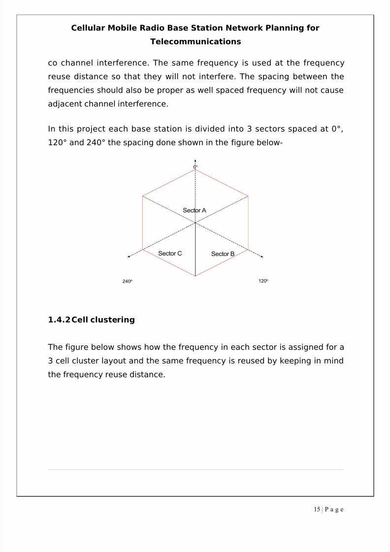
In this project each base station is divided into 3 sectors spaced at 0°,
120° and 240° the spacing done shown in the figure below-
0o
240o 120o
Sector A
Sector BSector C
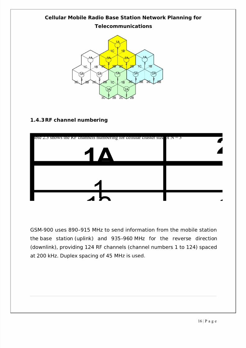
1.4.2Cell clustering
The figure below shows how the frequency in each sector is assigned for a
3 cell cluster layout and the same frequency is reused by keeping in mind
the frequency reuse distance.
15 | P a g e
8/3/2019 Tde Final Report
http://slidepdf.com/reader/full/tde-final-report 16/37
Cellular Mobile Radio Base Station Network Planning for
Telecommunications
1
23
1A
2A3A
1B
2B3B
1C
2C3C1
23
1A
2A3A
1B
2B3B
1C
2C3C
1
23
1A
2A3A
1B
2B3B
1C
2C3C
1
23
1A
2A3A
1B
2B3B
1C
2C3C
1.4.3RF channel numbering
Table 2.3 shows the RF channels numbering for cellular cluster size of N = 3
1A
1
GSM-900 uses 890–915 MHz to send information from the mobile station
the base station (uplink) and 935–960 MHz for the reverse direction
(downlink), providing 124 RF channels (channel numbers 1 to 124) spaced
at 200 kHz. Duplex spacing of 45 MHz is used.
16 | P a g e
8/3/2019 Tde Final Report
http://slidepdf.com/reader/full/tde-final-report 17/37
Cellular Mobile Radio Base Station Network Planning for
Telecommunications
1.5 Base Station Site Configuration
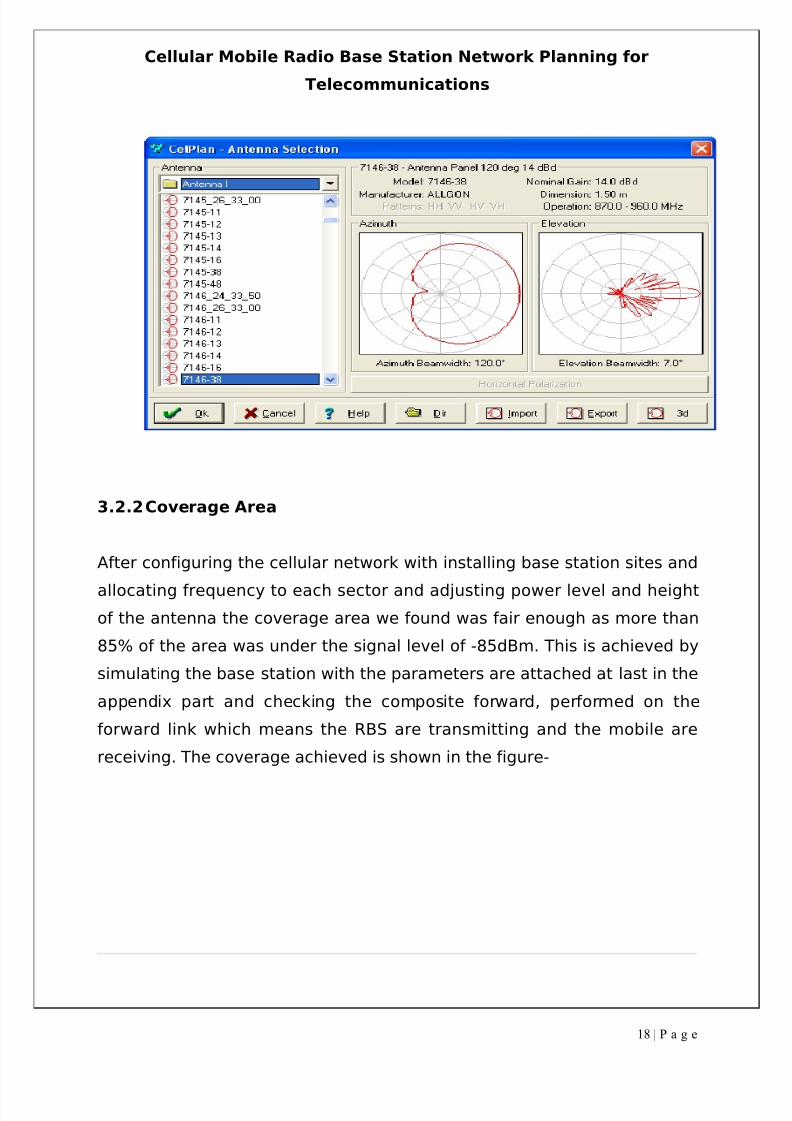
1.5.1 Antenna configuration
This project is designed by selecting the antenna model 7146-38 which is
highly directional with a gain of 14dBd. Although it has many side lobes
which is alright as it does not create any null. The elevation beamwidth is
7.0 which is very small and hence effective in providing a good coverage
area. Also this antenna is well suitable for the 120° sectoring pattern cell.
As this antenna is highly directional, thus giving excellent coverage.
The reason behind the selection of this antenna is that its beamwidth isnot too narrow or too wide as it has to be directional because sectoring is
done and in case to reduce interference if tilting is needed we can do
easily because tilting an antenna whose beamwidth is not narrow will not
make any difference in the coverage and interference. Also at last the
coverage achieved by this antenna under the frequency range is the best
and that is why the antenna model 7146-38 is the best and thus chosen.
The figure below shows the antenna specification with azimuth andelevation beamwidth
17 | P a g e
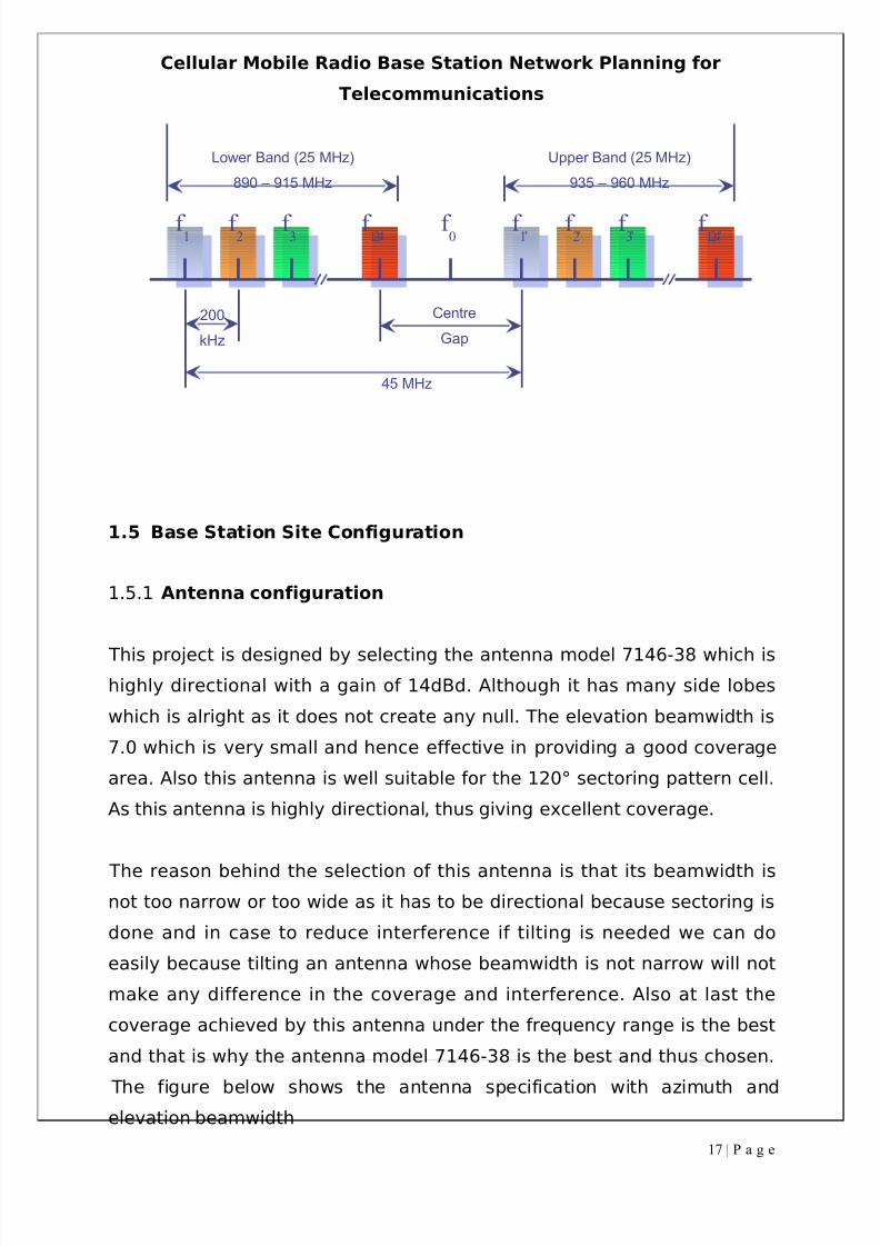
f 1 f 3f 2 f 124 f 1’ f 3’f 2’ f 124’f 0
Lower Band (25 MHz)
890 – 915 MHz
Upper Band (25 MHz)
935 – 960 MHz
Centre
Gap
45 MHz
200
kHz
8/3/2019 Tde Final Report
http://slidepdf.com/reader/full/tde-final-report 18/37
Cellular Mobile Radio Base Station Network Planning for
Telecommunications
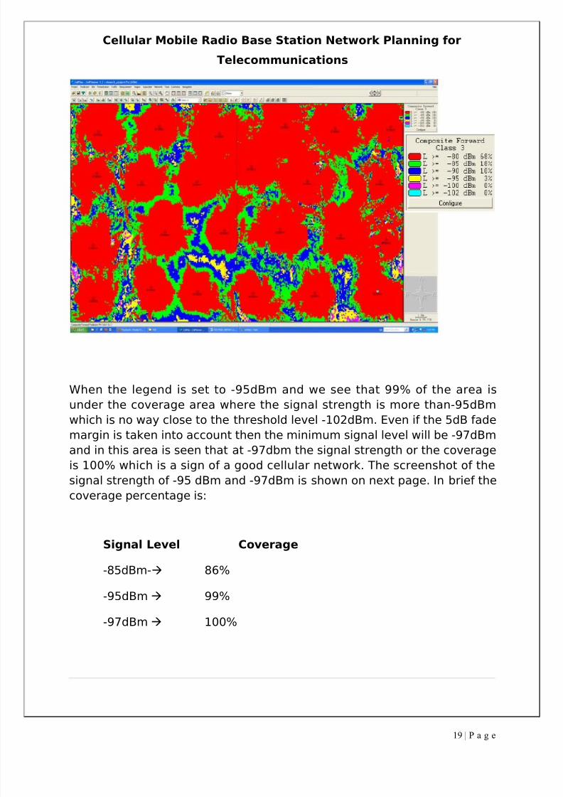
3.2.2Coverage Area
After configuring the cellular network with installing base station sites and
allocating frequency to each sector and adjusting power level and height
of the antenna the coverage area we found was fair enough as more than
85% of the area was under the signal level of -85dBm. This is achieved by
simulating the base station with the parameters are attached at last in the
appendix part and checking the composite forward, performed on the
forward link which means the RBS are transmitting and the mobile are
receiving. The coverage achieved is shown in the figure-
18 | P a g e
8/3/2019 Tde Final Report
http://slidepdf.com/reader/full/tde-final-report 19/37
Cellular Mobile Radio Base Station Network Planning for
Telecommunications
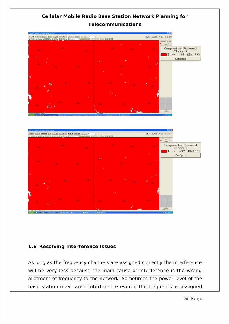
When the legend is set to -95dBm and we see that 99% of the area is
under the coverage area where the signal strength is more than-95dBm
which is no way close to the threshold level -102dBm. Even if the 5dB fademargin is taken into account then the minimum signal level will be -97dBm
and in this area is seen that at -97dbm the signal strength or the coverage
is 100% which is a sign of a good cellular network. The screenshot of the
signal strength of -95 dBm and -97dBm is shown on next page. In brief the
coverage percentage is:
Signal Level Coverage
-85dBm- 86%
-95dBm 99%
-97dBm 100%
19 | P a g e
8/3/2019 Tde Final Report
http://slidepdf.com/reader/full/tde-final-report 20/37
Cellular Mobile Radio Base Station Network Planning for
Telecommunications
1.6 Resolving Interference Issues
As long as the frequency channels are assigned correctly the interference
will be very less because the main cause of interference is the wrong
allotment of frequency to the network. Sometimes the power level of the
base station may cause interference even if the frequency is assigned
20 | P a g e
8/3/2019 Tde Final Report
http://slidepdf.com/reader/full/tde-final-report 21/37
8/3/2019 Tde Final Report
http://slidepdf.com/reader/full/tde-final-report 22/37
Cellular Mobile Radio Base Station Network Planning for
Telecommunications
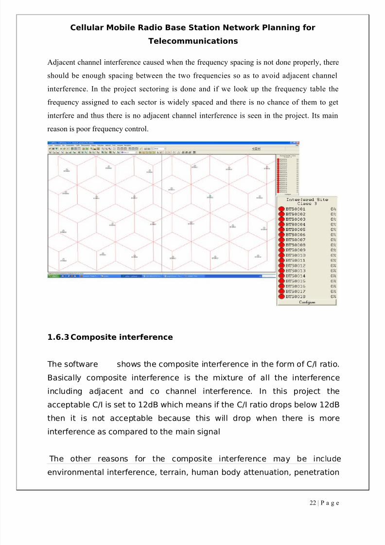
Adjacent channel interference caused when the frequency spacing is not done properly, there
should be enough spacing between the two frequencies so as to avoid adjacent channel
interference. In the project sectoring is done and if we look up the frequency table the
frequency assigned to each sector is widely spaced and there is no chance of them to get
interfere and thus there is no adjacent channel interference is seen in the project. Its main
reason is poor frequency control.
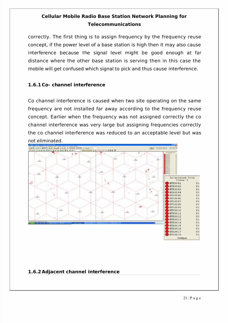
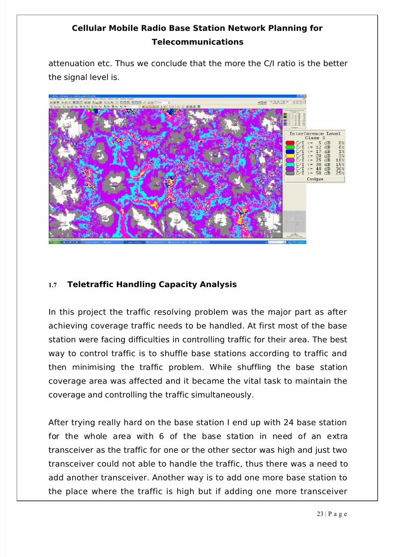
1.6.3Composite interference
The software shows the composite interference in the form of C/I ratio.
Basically composite interference is the mixture of all the interference
including adjacent and co channel interference. In this project the
acceptable C/I is set to 12dB which means if the C/I ratio drops below 12dB
then it is not acceptable because this will drop when there is more
interference as compared to the main signal
The other reasons for the composite interference may be include
environmental interference, terrain, human body attenuation, penetration
22 | P a g e
8/3/2019 Tde Final Report
http://slidepdf.com/reader/full/tde-final-report 23/37
Cellular Mobile Radio Base Station Network Planning for
Telecommunications
attenuation etc. Thus we conclude that the more the C/I ratio is the better
the signal level is.
1.7 Teletraffic Handling Capacity Analysis
In this project the traffic resolving problem was the major part as after
achieving coverage traffic needs to be handled. At first most of the base
station were facing difficulties in controlling traffic for their area. The best
way to control traffic is to shuffle base stations according to traffic and
then minimising the traffic problem. While shuffling the base station
coverage area was affected and it became the vital task to maintain the
coverage and controlling the traffic simultaneously.
After trying really hard on the base station I end up with 24 base station
for the whole area with 6 of the base station in need of an extra
transceiver as the traffic for one or the other sector was high and just two
transceiver could not able to handle the traffic, thus there was a need to
add another transceiver. Another way is to add one more base station to
the place where the traffic is high but if adding one more transceiver
23 | P a g e
8/3/2019 Tde Final Report
http://slidepdf.com/reader/full/tde-final-report 24/37
Cellular Mobile Radio Base Station Network Planning for
Telecommunications
solves the problem then adding a base station would be wastage of lot of
money as installing another base station is costly in comparison to adding
a transceiver.
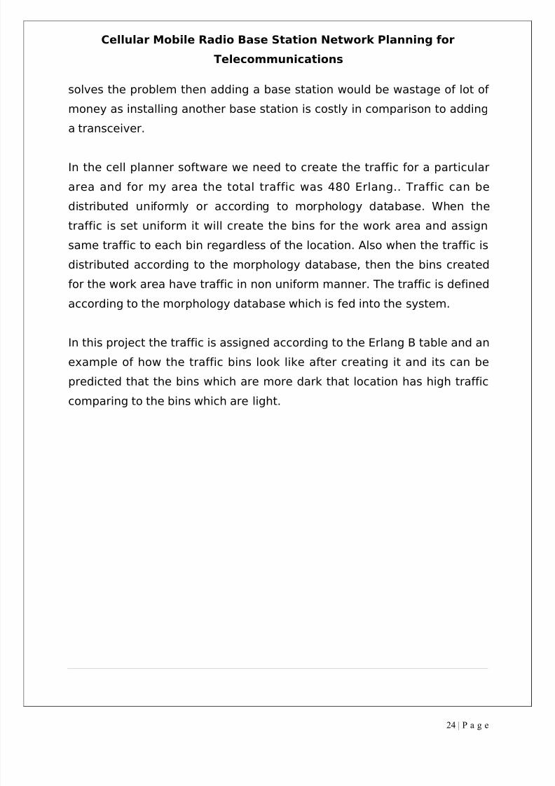
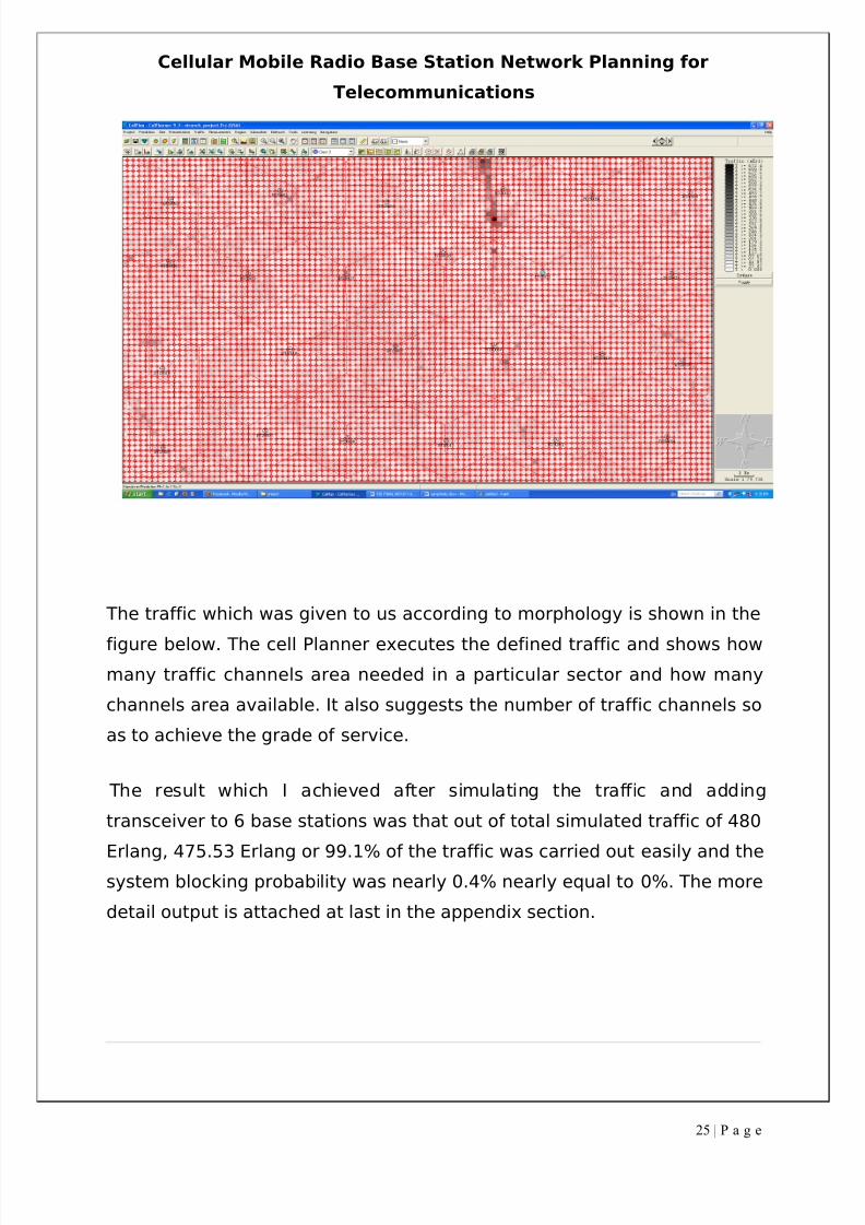
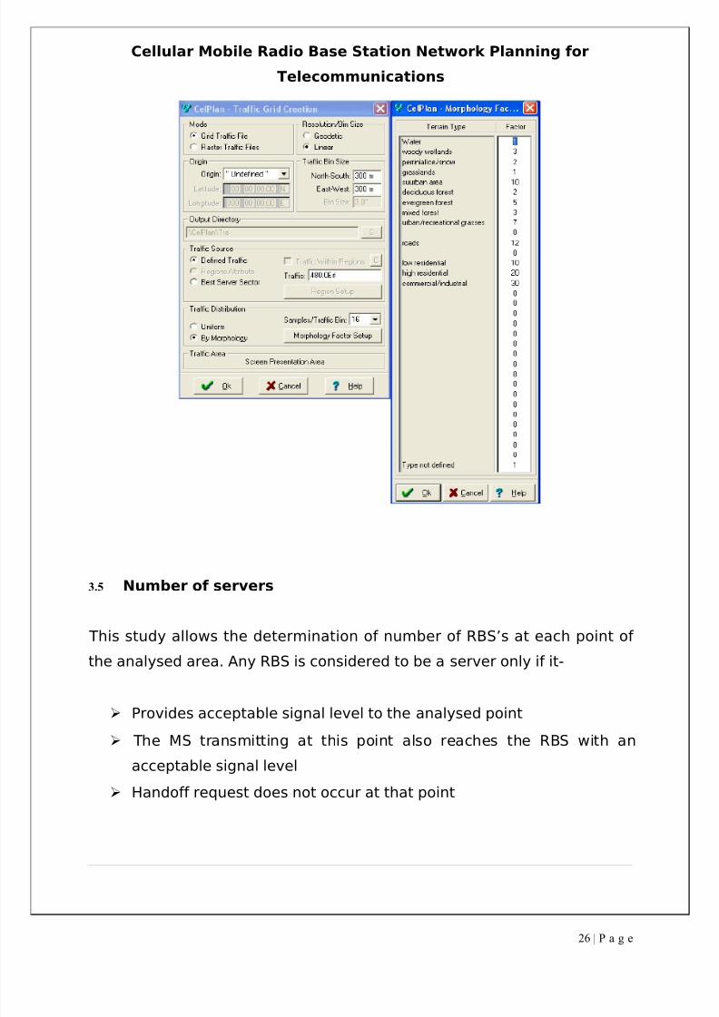
In the cell planner software we need to create the traffic for a particular
area and for my area the total traffic was 480 Erlang.. Traffic can be
distributed uniformly or according to morphology database. When the
traffic is set uniform it will create the bins for the work area and assign
same traffic to each bin regardless of the location. Also when the traffic is
distributed according to the morphology database, then the bins created
for the work area have traffic in non uniform manner. The traffic is defined
according to the morphology database which is fed into the system.
In this project the traffic is assigned according to the Erlang B table and an
example of how the traffic bins look like after creating it and its can be
predicted that the bins which are more dark that location has high traffic
comparing to the bins which are light.
24 | P a g e
8/3/2019 Tde Final Report
http://slidepdf.com/reader/full/tde-final-report 25/37
8/3/2019 Tde Final Report
http://slidepdf.com/reader/full/tde-final-report 26/37
8/3/2019 Tde Final Report
http://slidepdf.com/reader/full/tde-final-report 27/37
Cellular Mobile Radio Base Station Network Planning for
Telecommunications
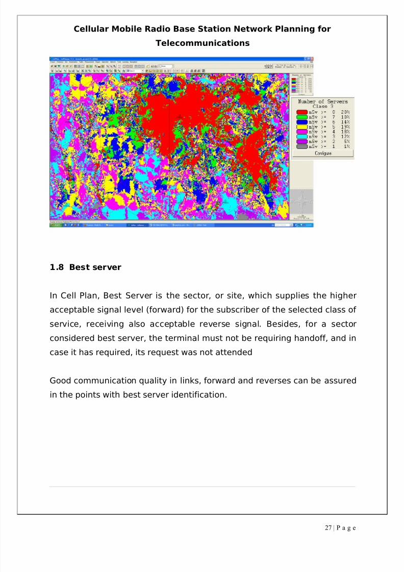
1.8 Best server
In Cell Plan, Best Server is the sector, or site, which supplies the higher
acceptable signal level (forward) for the subscriber of the selected class of
service, receiving also acceptable reverse signal. Besides, for a sector
considered best server, the terminal must not be requiring handoff, and in
case it has required, its request was not attended
Good communication quality in links, forward and reverses can be assured
in the points with best server identification.
27 | P a g e
8/3/2019 Tde Final Report
http://slidepdf.com/reader/full/tde-final-report 28/37
Cellular Mobile Radio Base Station Network Planning for
Telecommunications
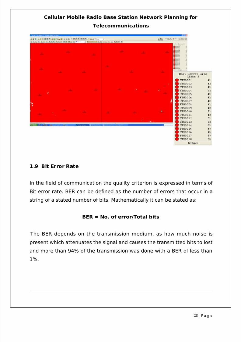
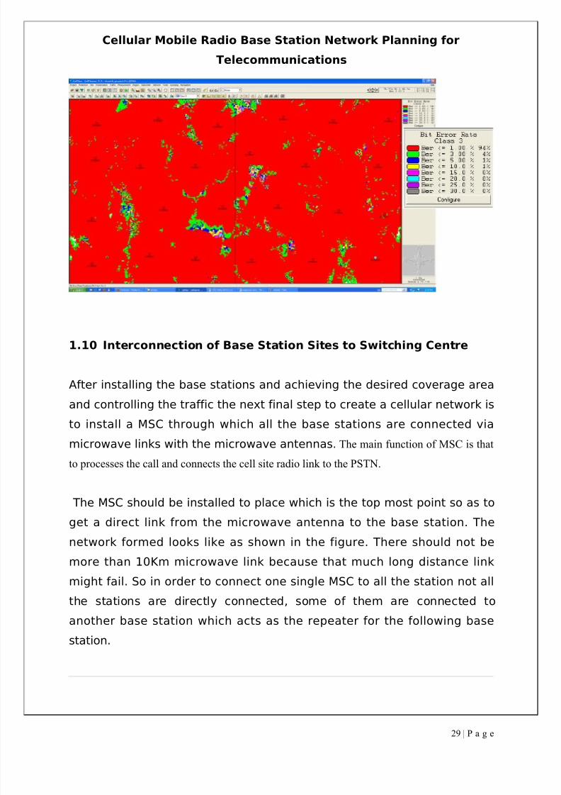
1.9 Bit Error Rate
In the field of communication the quality criterion is expressed in terms of
Bit error rate. BER can be defined as the number of errors that occur in a
string of a stated number of bits. Mathematically it can be stated as:
BER = No. of error/Total bits
The BER depends on the transmission medium, as how much noise is
present which attenuates the signal and causes the transmitted bits to lost
and more than 94% of the transmission was done with a BER of less than
1%.
28 | P a g e
8/3/2019 Tde Final Report
http://slidepdf.com/reader/full/tde-final-report 29/37
Cellular Mobile Radio Base Station Network Planning for
Telecommunications
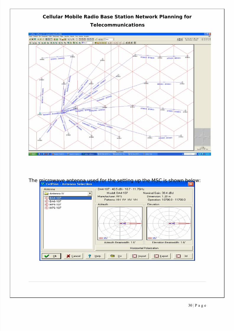
1.10 Interconnection of Base Station Sites to Switching Centre
After installing the base stations and achieving the desired coverage area
and controlling the traffic the next final step to create a cellular network is
to install a MSC through which all the base stations are connected via
microwave links with the microwave antennas. The main function of MSC is that
to processes the call and connects the cell site radio link to the PSTN.
The MSC should be installed to place which is the top most point so as to
get a direct link from the microwave antenna to the base station. The
network formed looks like as shown in the figure. There should not be
more than 10Km microwave link because that much long distance link
might fail. So in order to connect one single MSC to all the station not all
the stations are directly connected, some of them are connected to
another base station which acts as the repeater for the following base
station.
29 | P a g e
8/3/2019 Tde Final Report
http://slidepdf.com/reader/full/tde-final-report 30/37
Cellular Mobile Radio Base Station Network Planning for
Telecommunications
The microwave antenna used for the setting up the MSC is shown below:
30 | P a g e
8/3/2019 Tde Final Report
http://slidepdf.com/reader/full/tde-final-report 31/37
Cellular Mobile Radio Base Station Network Planning for
Telecommunications
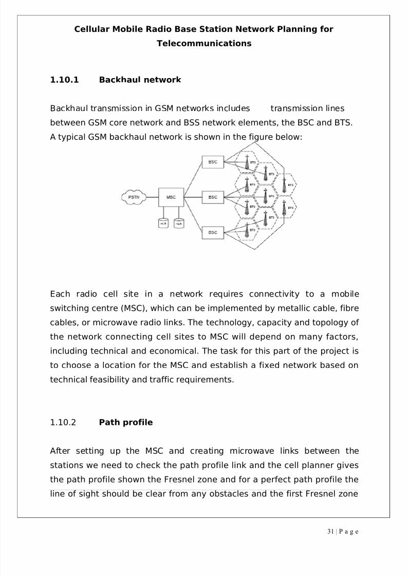
1.10.1 Backhaul network
Backhaul transmission in GSM networks includes transmission lines
between GSM core network and BSS network elements, the BSC and BTS.
A typical GSM backhaul network is shown in the figure below:
Each radio cell site in a network requires connectivity to a mobile
switching centre (MSC), which can be implemented by metallic cable, fibre
cables, or microwave radio links. The technology, capacity and topology of
the network connecting cell sites to MSC will depend on many factors,
including technical and economical. The task for this part of the project is
to choose a location for the MSC and establish a fixed network based on
technical feasibility and traffic requirements.
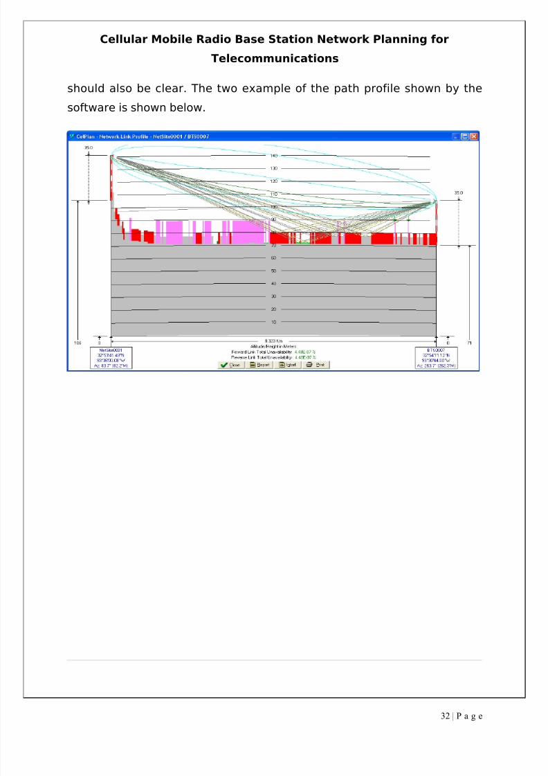
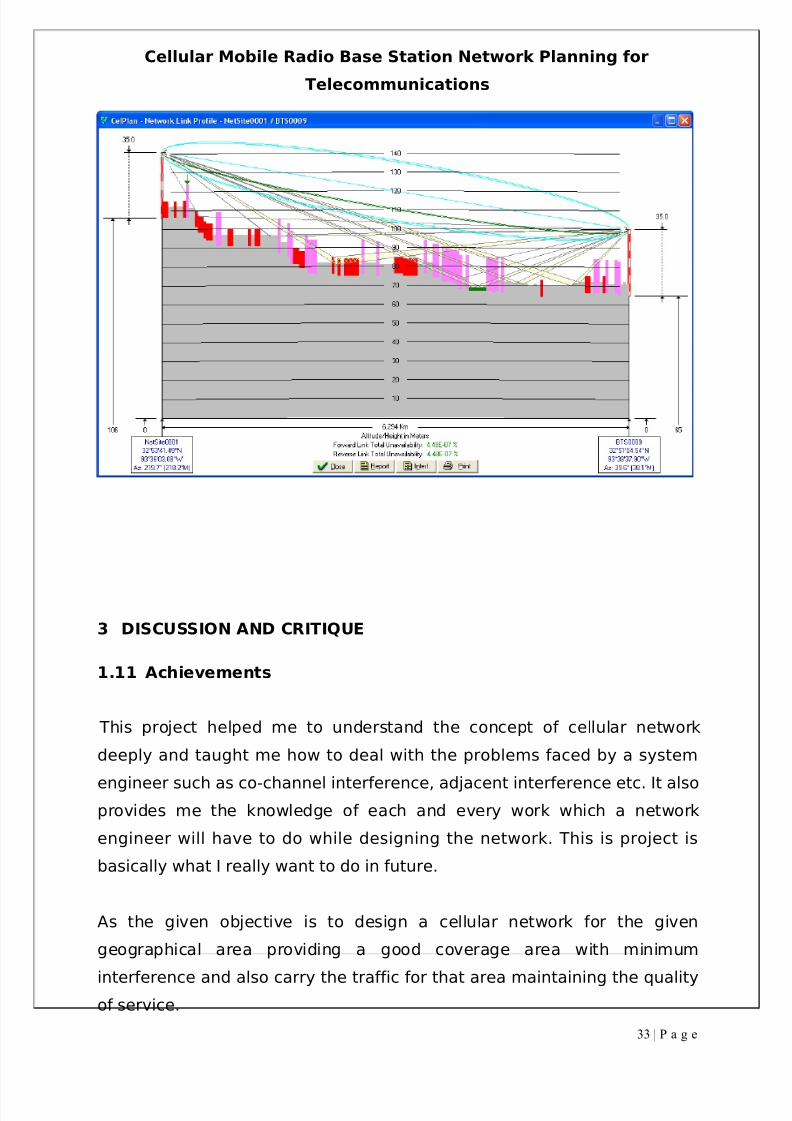
1.10.2 Path profile
After setting up the MSC and creating microwave links between the
stations we need to check the path profile link and the cell planner gives
the path profile shown the Fresnel zone and for a perfect path profile the
line of sight should be clear from any obstacles and the first Fresnel zone
31 | P a g e
8/3/2019 Tde Final Report
http://slidepdf.com/reader/full/tde-final-report 32/37
Cellular Mobile Radio Base Station Network Planning for
Telecommunications
should also be clear. The two example of the path profile shown by the
software is shown below.
32 | P a g e
8/3/2019 Tde Final Report
http://slidepdf.com/reader/full/tde-final-report 33/37
Cellular Mobile Radio Base Station Network Planning for
Telecommunications
3 DISCUSSION AND CRITIQUE
1.11 Achievements
This project helped me to understand the concept of cellular network
deeply and taught me how to deal with the problems faced by a system
engineer such as co-channel interference, adjacent interference etc. It alsoprovides me the knowledge of each and every work which a network
engineer will have to do while designing the network. This is project is
basically what I really want to do in future.
As the given objective is to design a cellular network for the given
geographical area providing a good coverage area with minimum
interference and also carry the traffic for that area maintaining the qualityof service.
33 | P a g e
8/3/2019 Tde Final Report
http://slidepdf.com/reader/full/tde-final-report 34/37
Cellular Mobile Radio Base Station Network Planning for
Telecommunications
The overall results achieved in this project are:
Coverage area 86% at signal level of -85dBm and 99% at signal level
of -95dBm
Co-channel interference was found to be negligible
Adjacent channel interference was zero percent
More than 99% was carried out easily
GoS achieved was 0.5%
This project is accomplished after installing 24 base stations withmaximum antenna height of 50m and power 50Watts and adding 6 extra
transceivers to few of the base stations in order to carry the simulated
traffic easily and maintaining the grade of service.
1.12 Difficulties Encountered
Major difficulties faced were:
Minimising the interference level as frequency reuse concept was
followed. So the frequency reuse distance is be maintained which
was a challenge.
The geographical area was uneven so in order to provide coverage
was a big ask and this was achieved by playing with the base station
parameters such as antenna pattern, height and power.
Traffic was the major concern in this project as there were many
areas where the traffic intensity was very high and only single base
station equipped with two transceivers in each sector was not
enough to handle the traffic. This problem was overcome by adding
one more base station or increasing the no. of transceiver.
Achieving a clear line of sight while creating the microwave links and
also the first Fresnel zone should be clear. This was easily carried
out by increasing the microwave antenna height or by creating a link
34 | P a g e
8/3/2019 Tde Final Report
http://slidepdf.com/reader/full/tde-final-report 35/37
Cellular Mobile Radio Base Station Network Planning for
Telecommunications
from MSC to a base station via another base station acting as a
repeater.
1.13 Points learned and Future Work
This project helped me developing the skills needed to design a
cellular network for a real geographical area and taught me to deal
with various difficulties which a system engineer might face while
doing it practically.
It provides me to understand and work on the software needed forthe designing of the cellular network called Cell Planner very well.
Through this software I learned the concept of terms like frequency
reuse, co-channel interference, handover, BER etc
Moreover it helped me to deal with the traffic in a particular area
and how to allocate each base station so that the traffic in whole
area is carried out efficiently.
Through this software I came to know about the setting up of MSCand how the microwave links can be established.
4 APPENDICES
1.13.1 CelPlanner Output
1.13.2 Traffic Simulation Result
35 | P a g e
8/3/2019 Tde Final Report
http://slidepdf.com/reader/full/tde-final-report 36/37
Cellular Mobile Radio Base Station Network Planning for
Telecommunications
5 REFERENCES
[1]Parsons, J. D., “The Mobile Radio Channel”, Second Edition, John Wiley
& Sons Ltd, 2000
[2]Garg, V. K., Wilkes, J E, "Wireless and Personal Communications
Systems", Prentice-Hall
[3]Garg, V. K., Wilkes, J E, "Principles and Applications of GSM, 1/e",
Prentice-Hall
36 | P a g e
8/3/2019 Tde Final Report
http://slidepdf.com/reader/full/tde-final-report 37/37
Cellular Mobile Radio Base Station Network Planning for
Telecommunications
[4]Lee, William C. Y., "Mobile Cellular Telecommunications: Analog and
Digital Systems", second Edition, McGraw-Hill, Inc.
[5]CelPlanner User Guide, CelPlanner Manuals, CelPlan Technologies, Inc.
[6] CelPlan Technologies, Inc. website www.celplan.com
[7]Project Specification