Embed Size (px)
Citation preview

1TD-000108-00 rev.A
*TD-000108-00* PowerLight Series
PowerLight 6.0 IIUser Manual
TM
2
© Copyright 2002, QSC Audio Products, Inc.QSC® is a registered trademark of QSC Audio Products, Inc.
“QSC” and the QSC logo are registered with the U.S. Patent and Trademark OfficeCombo is a registered trademark of Neutrik Inc., Lakewood, NJ .
Speakon™ is a registered trademark of Neutrik Inc., Lakewood, NJ
IMPORTANT SAFETY INSTRUCTIONS& EXPLANATION OF SYMBOLS
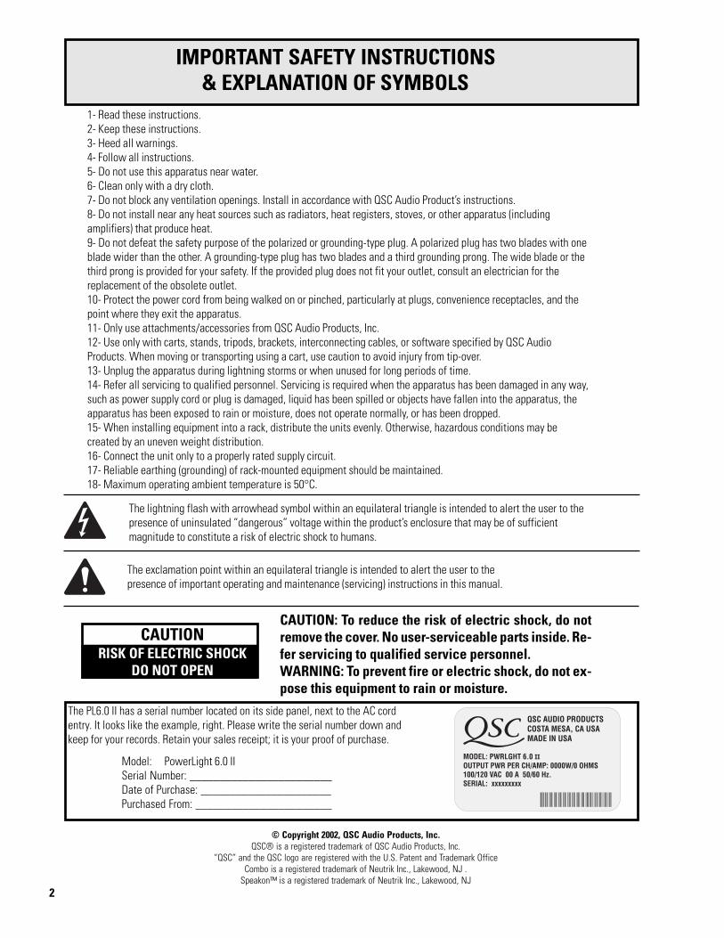
The lightning flash with arrowhead symbol within an equilateral triangle is intended to alert the user to thepresence of uninsulated “dangerous” voltage within the product’s enclosure that may be of sufficientmagnitude to constitute a risk of electric shock to humans.
The exclamation point within an equilateral triangle is intended to alert the user to thepresence of important operating and maintenance (servicing) instructions in this manual.
The PL6.0 II has a serial number located on its side panel, next to the AC cordentry. It looks like the example, right. Please write the serial number down andkeep for your records. Retain your sales receipt; it is your proof of purchase.
Model: PowerLight 6.0 IISerial Number: ________________________Date of Purchase: ______________________Purchased From: _______________________
1- Read these instructions.2- Keep these instructions.3- Heed all warnings.4- Follow all instructions.5- Do not use this apparatus near water.6- Clean only with a dry cloth.7- Do not block any ventilation openings. Install in accordance with QSC Audio Product’s instructions.8- Do not install near any heat sources such as radiators, heat registers, stoves, or other apparatus (includingamplifiers) that produce heat.9- Do not defeat the safety purpose of the polarized or grounding-type plug. A polarized plug has two blades with oneblade wider than the other. A grounding-type plug has two blades and a third grounding prong. The wide blade or thethird prong is provided for your safety. If the provided plug does not fit your outlet, consult an electrician for thereplacement of the obsolete outlet.10- Protect the power cord from being walked on or pinched, particularly at plugs, convenience receptacles, and thepoint where they exit the apparatus.11- Only use attachments/accessories from QSC Audio Products, Inc.12- Use only with carts, stands, tripods, brackets, interconnecting cables, or software specified by QSC AudioProducts. When moving or transporting using a cart, use caution to avoid injury from tip-over.13- Unplug the apparatus during lightning storms or when unused for long periods of time.14- Refer all servicing to qualified personnel. Servicing is required when the apparatus has been damaged in any way,such as power supply cord or plug is damaged, liquid has been spilled or objects have fallen into the apparatus, theapparatus has been exposed to rain or moisture, does not operate normally, or has been dropped.15- When installing equipment into a rack, distribute the units evenly. Otherwise, hazardous conditions may becreated by an uneven weight distribution.16- Connect the unit only to a properly rated supply circuit.17- Reliable earthing (grounding) of rack-mounted equipment should be maintained.18- Maximum operating ambient temperature is 50°C.
CAUTIONRISK OF ELECTRIC SHOCK
DO NOT OPEN
CAUTION: To reduce the risk of electric shock, do notremove the cover. No user-serviceable parts inside. Re-fer servicing to qualified service personnel.WARNING: To prevent fire or electric shock, do not ex-pose this equipment to rain or moisture.

3
INTRODUCTIONOverview...........................................................................................4I l lustrat ions. . . . . . . . . . . . . . . . . . . . . . . . . . . . . . . . . . . . . . . . . . . . . . . . . . . . . . . . . . . . . . . . . . . . . . . . . . . . .5
UNPACKINGUnpacking and Inspection..................................................................................6What is Included.............................................................................................6
SETUPRack Mounting.................................................................................................................6Cooling Requirements.................................................................................................8AC Power Requirements..............................................................................9Operating Mode Selection............................................................................10
CONNECTIONSInputs...........................................................................................................12DataPort. . . . . . . . . . . . . . . . . . . . . . . . . . . . . . . . . . . . . . . . . . . . . . . . . . . . . . . . . . . . . . . . . . . . . . . . . . . . . . . . . . . .14Power Supply Remote Control....................................................................16Outputs: Binding Posts...............................................................................17Outputs: Speakons™.....................................................................................18
USEPower Switch...........................................................................................19Power, Standby and Protect LED indicators.............................................19Gain Controls.............................................................................................20Signal, -20 dB, -10 dB, and Clip LED indicators........................................................20Clip Limiters..................................................................................................21
TROUBLESHOOTING...................................................................................22
SPECIFICATIONS............................................................................................................24
APPENDIXDataPort Pinout..............................................................................................25QSC PowerWave Technology Overview...........................................................26
WARRANTY INFORMATION .............................................................................................27
HOW TO CONTACT QSC AUDIO PRODUCTS .........................................................27
TABLE OF CONTENTS
4
INTRODUCTION- General Overview
Thank you and congratulations on your purchaseof the QSC PowerLight 6.0 II professional poweramplifier. This product represents the state-of-the-art in power amplification systems forprofessional touring, permanent installations,and other SR (sound reinforcement) applicationsrequiring high levels of sustained power,extraordinary audio performance, reducedweight, and road-proven reliability. To get themost from your investment, we encourage youto review this manual carefully.
Part of the advanced technology PowerLightfamily of amplifiers, the PowerLight 6.0 IIbenefits from QSC’s exclusive PowerWaveswitching technology, its DataPort for remotecomputer control, and an enhanced design thatprovides greater airflow through the chassis—facilitating cooler, more efficient operation.
QSC PowerWave TechnologyQSC’s PowerWave switching power supplytechnology provides ample current to the audiopower circuitry by charging the supply rails180,000 times per second through an ultra-lowimpedance circuit. This high-efficiency design
cuts waste heat and boosts reliability whiledelivering the added benefits of tighter bass andtransparent highs for a more musical sound.
The PowerLight 6.0 II utilizes an enhanced,second-generation power supply design. Thisnew design reduces both EMI (electromagneticinterference) and the overall weight of theunit—enabling far greater placement optionswhen positioning equipment. In the unlikelyevent your unit ever requires service, the newpower supply design offers several additionalbenefits—including greater ease of service,resulting in reduced labor time and lowerreplacement costs.
Remote Computer ControlThe PowerLight 6.0 II also incorporates QSC’sunique DataPort for remote computer control.Using QSControl, QSC’s network audio system,you can monitor and control hundreds of amplifi-ers simultaneously, as well as perform a widerange of advanced functions—including eventlogging, checking the thermal status of theamplifier, plus real-time monitoring of loud-speaker opens and shorts.
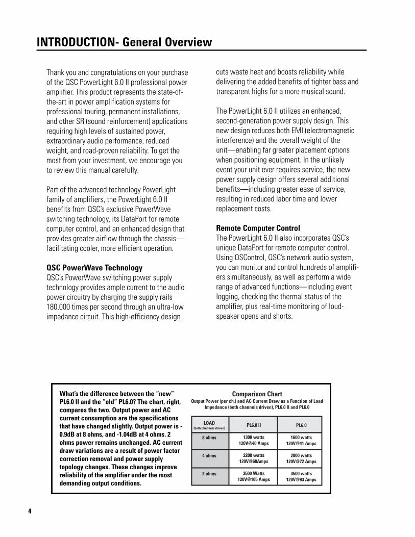
What’s the difference between the “new”PL6.0 II and the “old” PL6.0? The chart, right,compares the two. Output power and ACcurrent consumption are the specificationsthat have changed slightly. Output power is -0.9dB at 8 ohms, and -1.04dB at 4 ohms. 2ohms power remains unchanged. AC currentdraw variations are a result of power factorcorrection removal and power supplytopology changes. These changes improvereliability of the amplifier under the mostdemanding output conditions.
5
INTRODUCTION- Illustrations
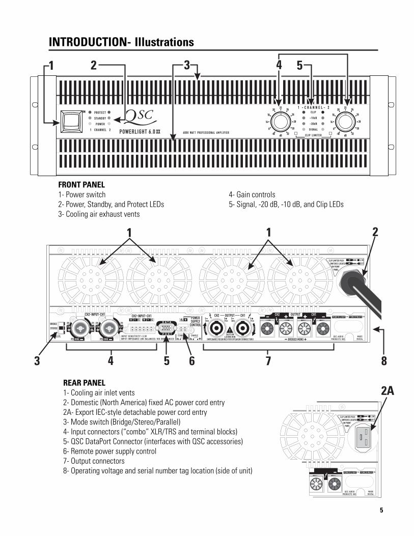
FRONT PANEL1- Power switch 4- Gain controls2- Power, Standby, and Protect LEDs 5- Signal, -20 dB, -10 dB, and Clip LEDs3- Cooling air exhaust vents
REAR PANEL1- Cooling air inlet vents2- Domestic (North America) fixed AC power cord entry2A- Export IEC-style detachable power cord entry3- Mode switch (Bridge/Stereo/Parallel)4- Input connectors (“combo” XLR/TRS and terminal blocks)5- QSC DataPort Connector (interfaces with QSC accessories)6- Remote power supply control7- Output connectors8- Operating voltage and serial number tag location (side of unit)

6
The PL6.0 II is highly durable and is carefully packaged. We recommend youinspect the unit carefully after removing it from the packaging, as occasionallythere may be damage due to some unfortunate incident during shipment. Reportany damage to the shipping carrier. We recommend saving the carton and packingmaterial. It is always a good idea to keep the packaging in case the unit must beshipped back to your dealer, distributor, or service center. Also note: some freightcompanies consider damage claims without the original packing materials invalid.
The QSC shipping box should contain:1- the PL6.0 II amplifier2- this Owner’s Manual3- accessory packet containing:
-rear rack ear mounting kit-terminal-block connectors for inputs and remote power supply control-four adhesive feet
Unpacking and Inspection
UNPACKING
Supporting the Front of the AmplifierRack mounting of the amplifier is optional. The PL6.0 II is designed to fit a normal 19-inch width equipment rack.Secure the front rack ears using four machine screws with washers, as shown below. Verify operating voltageprinted on the serial number plate; it is located on the side panel by the AC cord entry. Once the amplifier ismounted, it may be difficult to read this information (see p.9).
CAUTION!To minimize therisk of injury, werecommend anassistant helpsupport theamplifier duringrack installation.
SETUP- Rack Mounting
When installingequipment into arack, distributethe units evenly.Otherwise, haz-ardous conditionsmay be created byan uneven weightdistribution.
7
SETUP- Rack Mounting
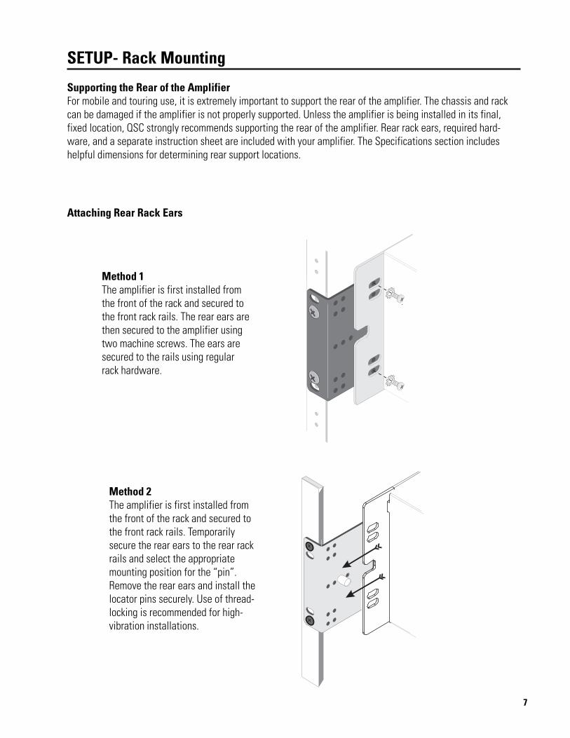
Supporting the Rear of the AmplifierFor mobile and touring use, it is extremely important to support the rear of the amplifier. The chassis and rackcan be damaged if the amplifier is not properly supported. Unless the amplifier is being installed in its final,fixed location, QSC strongly recommends supporting the rear of the amplifier. Rear rack ears, required hard-ware, and a separate instruction sheet are included with your amplifier. The Specifications section includeshelpful dimensions for determining rear support locations.
Method 2The amplifier is first installed fromthe front of the rack and secured tothe front rack rails. Temporarilysecure the rear ears to the rear rackrails and select the appropriatemounting position for the “pin”.Remove the rear ears and install thelocator pins securely. Use of thread-locking is recommended for high-vibration installations.
Attaching Rear Rack Ears
Method 1The amplifier is first installed fromthe front of the rack and secured tothe front rack rails. The rear ears arethen secured to the amplifier usingtwo machine screws. The ears aresecured to the rails using regularrack hardware.
8
SETUP- Cooling Requirements
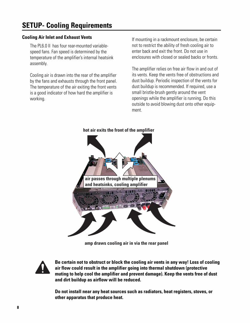
The PL6.0 II has four rear-mounted variable-speed fans. Fan speed is determined by thetemperature of the amplifier’s internal heatsinkassembly.
Cooling air is drawn into the rear of the amplifierby the fans and exhausts through the front panel.The temperature of the air exiting the front ventsis a good indicator of how hard the amplifier isworking.
If mounting in a rackmount enclosure, be certainnot to restrict the ability of fresh cooling air toenter back and exit the front. Do not use inenclosures with closed or sealed backs or fronts.
The amplifier relies on free air flow in and out ofits vents. Keep the vents free of obstructions anddust buildup. Periodic inspection of the vents fordust buildup is recommended. If required, use asmall bristle-brush gently around the ventopenings while the amplifier is running. Do thisoutside to avoid blowing dust onto other equip-ment.
Be certain not to obstruct or block the cooling air vents in any way! Loss of coolingair flow could result in the amplifier going into thermal shutdown (protectivemuting to help cool the amplifier and prevent damage). Keep the vents free of dustand dirt buildup as airflow will be reduced.
Do not install near any heat sources such as radiators, heat registers, stoves, orother apparatus that produce heat.
Cooling Air Inlet and Exhaust Vents

9
SETUP- AC Power RequirementsAC Power
Before connecting the amplifier to the ACmains, check the serial number plate toverify operating voltage.
The PL6.0 II is available in 120 or 240 Voltmodels. Make sure the AC mains voltage isthe same as specified on the serial numberplate.
120 Volt models have the AC cordset hard-wired to the chassis. 240 Volt models havean IEC-style detachable cordset.
Do not use improper ACmains voltage! It cancreate hazardous condi-tions and severely dam-age the amplifier!
The PL6.0 II is a very high-power amplifier and as such can demand high currentfrom the AC service. All connections must be properly rated for reliable operation.
Use of extension cords is discouraged. If extension cords must be used, use onlyheavy-duty 10 gauge extension cords that are as short as possible.
AC Power Connection
120 Volt ModelsNEMA L5-30 ReceptacleConnect the 30 Amp twist-lock connectors byorienting the locking L-shaped prong with thecorresponding connector entry, then fully insertthe three prongs. Twist the plug about 1/8 of aturn clockwise to lock the connector and plug.
240 Volt ModelsEuropean 3-conductor Earthing ReceptacleInsert the plug fully into the receptacle.
10
SETUP- Operating Mode Selection
Stereo Mode
Operating Mode Selection
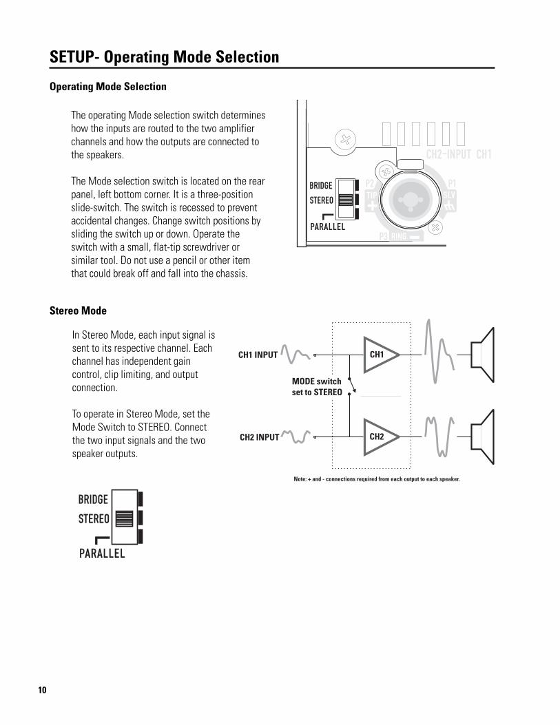
The operating Mode selection switch determineshow the inputs are routed to the two amplifierchannels and how the outputs are connected tothe speakers.
The Mode selection switch is located on the rearpanel, left bottom corner. It is a three-positionslide-switch. The switch is recessed to preventaccidental changes. Change switch positions bysliding the switch up or down. Operate theswitch with a small, flat-tip screwdriver orsimilar tool. Do not use a pencil or other itemthat could break off and fall into the chassis.
In Stereo Mode, each input signal issent to its respective channel. Eachchannel has independent gaincontrol, clip limiting, and outputconnection.
To operate in Stereo Mode, set theMode Switch to STEREO. Connectthe two input signals and the twospeaker outputs.

11
Parallel Mode
Bridge Mode
In Parallel Mode, the channel 1 andchannel 2 input connectors areconnected in parallel. Applying aninput signal to either input will driveboth channels. Make sure only oneinput signal is applied to the ampli-fier when operating in Parallel mode.Each channel still has independentgain control, clip limiting, and outputconnection, just like Stereo Mode.
To operate in Parallel Mode, set theMode Switch to PARALLEL. Connectthe single input signal and the twospeaker channels.
In Bridge Mode, both output chan-nels are combined into one higherpower channel. The result is oneoutput with about 4 times the peakpower and about 3 times the sus-tained power of a single channel.Use only CH1’s input. Output connec-tions for Bridge Mode are the twored binding posts. Connectionpolarity is clearly marked (CH1 redbinding post= positive, CH2 redbinding post= negative).
To operate in Bridge Mode, set theMode Switch to the BRIDGE position.Connect the single input and thesingle speaker channel.
SETUP- Operating Mode Selection
Speakon connectors are not recommended forBridge mode use! Use binding post outputs.Speakons are not wired for Bridge mode output!

12
Audio Input Connections
CONNECTIONS- Inputs
Input connections to the PL6.0 II can be madewith XLR, TRS (1/4-inch), or terminal-blockconnectors.
The XLR/TRS connectors are “combo” style; theyaccept either XLR or TRS type inputs.
The terminal block connectors are three-pin“Euro-” (or “Phoenix-”) type. The accessorypacket shipped with your amplifier contains twoof these input connectors.
Each channel’s input connectors are wired inparallel (example: Ch1’s combo connector iswired in parallel with CH1’s terminal blockconnector). This is useful for daisy-chaining theinput signal to other equipment. If you are usingthe “combo” connector for input, the terminal-block connector can be used for daisy-chaining. Ifusing the terminal-block for input, the “combos”can be used for daisy-chaining. Remember todisconnect unused inputs; any input signal oneither input connector will be amplified andoutput.
Combo input jack accepts bothXLR and TRS (1/4-inch) plugs.
Terminal-block jackaccepts 3-pin terminal-block plugs.
Use balanced connectionsand high-quality cable andconnectors for best results.
If the Mode Switch is set to PARALLEL, all inputconnectors (CH1 and CH2) are connected inparallel. An input signal applied to any of the fourinput connectors will drive the amplifier. Any ofthe unused inputs may be used to daisy-chain theinput signal to other equipment. Make sure onlyone input signal is applied to the amplifier.
The inputs are electronically balanced. To main-tain the benefits of balanced connections, makeall connections using balanced, high-quality cableand connectors. If balanced inputs are notavailable, use an unbalanced-to-balanced con-verter, such as a “DI” box or proper audio trans-former. If the input cables are short and the venuelocation free of electrical noise, unbalanced inputconnections may be acceptable. This is not thepreferred method, but sometimes necessary. Nodamage will be done using unbalanced connec-tions, just a reduction in audio quality andperformance.
Unbalanced connections are prone to noise andinterference pickup as well as ground-loopinduced hum. If your system has noise or hum,disconnect all amplifier inputs to verify the sourceof the noise. If the noise disappears, the noisesource is not the amplifier. Check cabling andother equipment connections.
13
XLR
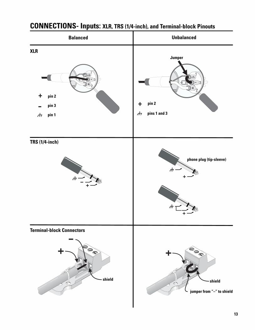
CONNECTIONS- Inputs: XLR, TRS (1/4-inch), and Terminal-block Pinouts
TRS (1/4-inch)
Terminal-block Connectors
phone plug (tip-sleeve)
shield
jumper from “–” to shield
shield
Balanced Unbalanced
pin 2
pins 1 and 3
Jumper
pin 2
pin 1
pin 3
14
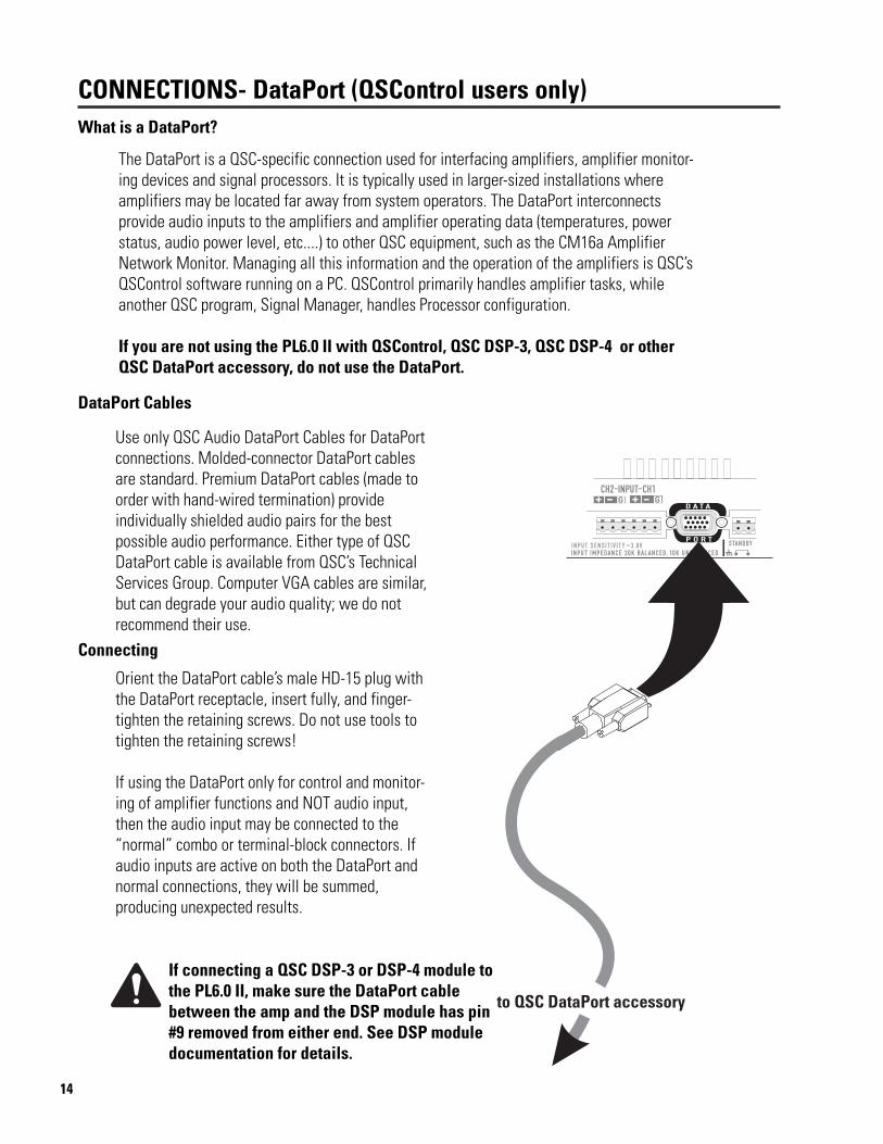
The DataPort is a QSC-specific connection used for interfacing amplifiers, amplifier monitor-ing devices and signal processors. It is typically used in larger-sized installations whereamplifiers may be located far away from system operators. The DataPort interconnectsprovide audio inputs to the amplifiers and amplifier operating data (temperatures, powerstatus, audio power level, etc....) to other QSC equipment, such as the CM16a AmplifierNetwork Monitor. Managing all this information and the operation of the amplifiers is QSC’sQSControl software running on a PC. QSControl primarily handles amplifier tasks, whileanother QSC program, Signal Manager, handles Processor configuration.
If you are not using the PL6.0 II with QSControl, QSC DSP-3, QSC DSP-4 or otherQSC DataPort accessory, do not use the DataPort.
What is a DataPort?
CONNECTIONS- DataPort (QSControl users only)
Orient the DataPort cable’s male HD-15 plug withthe DataPort receptacle, insert fully, and finger-tighten the retaining screws. Do not use tools totighten the retaining screws!
If using the DataPort only for control and monitor-ing of amplifier functions and NOT audio input,then the audio input may be connected to the“normal” combo or terminal-block connectors. Ifaudio inputs are active on both the DataPort andnormal connections, they will be summed,producing unexpected results.
DataPort Cables
Use only QSC Audio DataPort Cables for DataPortconnections. Molded-connector DataPort cablesare standard. Premium DataPort cables (made toorder with hand-wired termination) provideindividually shielded audio pairs for the bestpossible audio performance. Either type of QSCDataPort cable is available from QSC’s TechnicalServices Group. Computer VGA cables are similar,but can degrade your audio quality; we do notrecommend their use.
Connecting
If connecting a QSC DSP-3 or DSP-4 module tothe PL6.0 II, make sure the DataPort cablebetween the amp and the DSP module has pin#9 removed from either end. See DSP moduledocumentation for details.
15
CONNECTIONS- DataPort (QSControl users only)
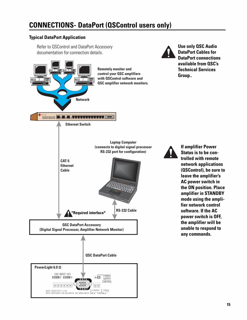
Use only QSC AudioDataPort Cables forDataPort connectionsavailable from QSC’sTechnical ServicesGroup..
If amplifier PowerStatus is to be con-trolled with remotenetwork applications(QSControl), be sure toleave the amplifier’sAC power switch inthe ON position. Placeamplifier in STANDBYmode using the ampli-fier network controlsoftware. If the ACpower switch is OFF,the amplifier will beunable to respond toany commands.
Typical DataPort Application
Refer to QSControl and DataPort Accessorydocumentation for connection details.
*Required interface*
16
CONNECTIONS- Power Supply Control (Standby/Enable)Remotely Controlling the Amplifier’s Power Status
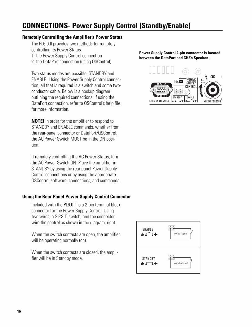
Power Supply Control 2-pin connector is locatedbetween the DataPort and CH2’s Speakon.
Using the Rear Panel Power Supply Control Connector
Included with the PL6.0 II is a 2-pin terminal blockconnector for the Power Supply Control. Usingtwo wires, a S.P.S.T. switch, and the connector,wire the control as shown in the diagram, right.
When the switch contacts are open, the amplifierwill be operating normally (on).
When the switch contacts are closed, the ampli-fier will be in Standby mode.
The PL6.0 II provides two methods for remotelycontrolling its Power Status:1- the Power Supply Control connection2- the DataPort connection (using QSControl)
Two status modes are possible: STANDBY andENABLE. Using the Power Supply Control connec-tion, all that is required is a switch and some two-conductor cable. Below is a hookup diagramoutlining the required connections. If using theDataPort connection, refer to QSControl’s help filefor more information.
NOTE! In order for the amplifier to respond toSTANDBY and ENABLE commands, whether fromthe rear-panel connector or DataPort/QSControl,the AC Power Switch MUST be in the ON posi-tion.
If remotely controlling the AC Power Status, turnthe AC Power Switch ON. Place the amplifier inSTANDBY by using the rear-panel Power SupplyControl connections or by using the appropriateQSControl software, connections, and commands.

17
CONNECTIONS- Outputs: Binding Posts
Connecting the Outputs to the Speakers
Use either the binding post or the Speakon™ output connections. Binding posts are covered on thispage, Speakons on the following page. Note that the PL6.0 II does not support Bridge mode outputfrom the Speakons (see page 11).
There are two basic speaker connection configurations for the PL6.0 II. Stereo and Parallel operatingmodes use two separate output channel connections. Bridge mode uses only one output channelconnection.
Refer to the chart below for connection diagrams. Mode Switch position is shown for reference.Speakon™ pinout is provided on the following page.
Do not use less than 4-ohm loads in Bridge mode! Note polarity of connectionsfor Bridge mode. Speakon connections do not support Bridge mode.Do not use banana-type plugs for connecting to binding posts. They will fail atthe high power levels of this amplifier!
18
CONNECTIONS- Outputs: Speakon™ pinout
Speakon Outputs
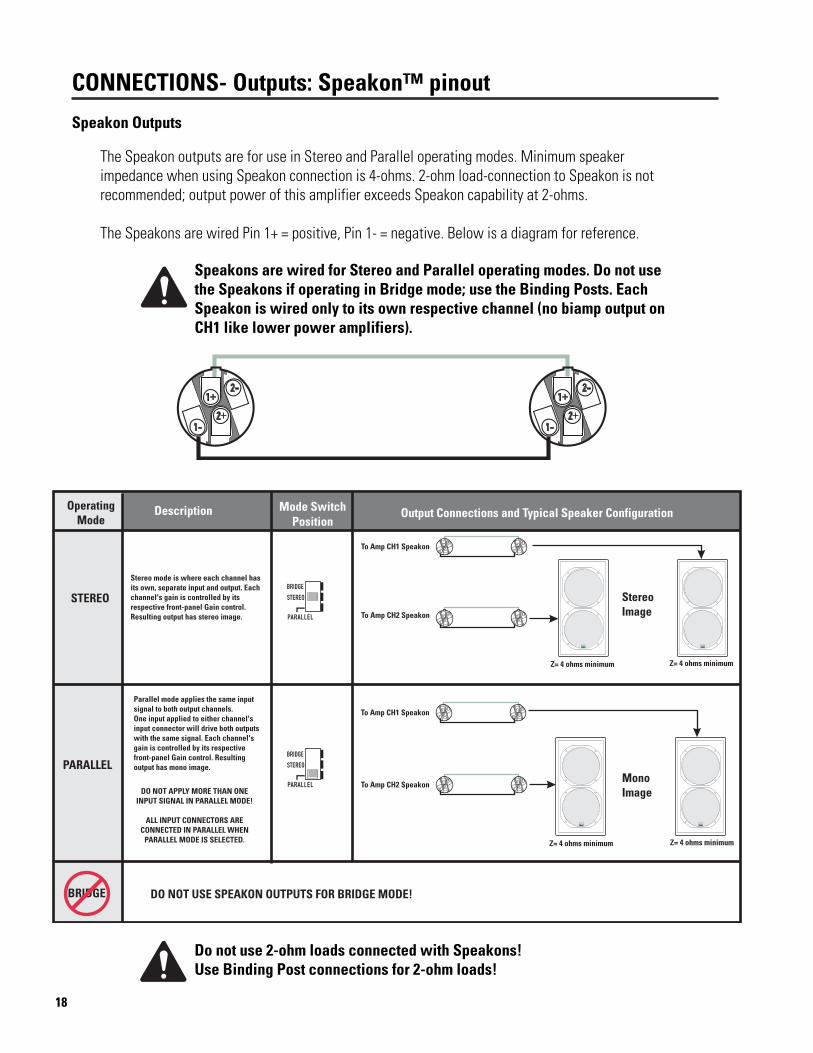
The Speakon outputs are for use in Stereo and Parallel operating modes. Minimum speakerimpedance when using Speakon connection is 4-ohms. 2-ohm load-connection to Speakon is notrecommended; output power of this amplifier exceeds Speakon capability at 2-ohms.
The Speakons are wired Pin 1+ = positive, Pin 1- = negative. Below is a diagram for reference.
Speakons are wired for Stereo and Parallel operating modes. Do not usethe Speakons if operating in Bridge mode; use the Binding Posts. EachSpeakon is wired only to its own respective channel (no biamp output onCH1 like lower power amplifiers).
Do not use 2-ohm loads connected with Speakons!Use Binding Post connections for 2-ohm loads!

19
USE- AC Power Switch and LED Indicators
LED Indicators for Power Status
On the left side of the front panel is the Power switch. The switch is labeled ON, above it and to the right.
To turn the power on: Press in on theupper portion of the rocker switch. Theamplifier will go through its power-upcycle; the red-colored Protect LEDs willilluminate briefly, then the green-coloredPower LEDs will remain on.
To turn the power off: Press in on thebottom portion of the rocker switch. It maytake a few moments for the Power LEDs toextinguish. This is normal.
AC Power Switch
To the right of the Power switch are six LEDs indicating the Power Status of the amplifier. The left column ofLEDs is for channel 1 and the right column for channel 2.
POWER- green LED indicating the amplifier is turned on and con-nected to a properly functioning AC source.
STANDBY- yellow LED, illuminates when the amplifier is put intoStandby mode by DataPort or Power Supply Remote Control connec-tor.
PROTECT- red LED, illuminates when the amplifier goes into protec-tive muting. This could be caused by shorted wiring or speakers,overheating, or amplifier failure. See Troubleshooting section.

20
USE- Signal Level LED Indicators
LED indicators.
USE- Gain Controls
Gain Controls
A Gain control adjustment is provided for eachchannel.
The voltage gain of the amplifier (in dB) ismarked around each control.
Rotating the control clockwise increases the gainof the amplifier. Rotating the control counter-clockwise reduces the gain of the amplifier.
In Stereo and Parallel operating modes (see p.10)each channel’s gain is adjusted by its respectivecontrol. In Bridge mode, use channel 1’s gaincontrol; channel 2’s control is ignored in bridgemode.
Signal Level LED IndicatorsBetween the Gain controls are eight LEDs indicating input signal level to the amplifier.The left column indicates channel 1’s input levels. The right column indicates channel2’s input levels. Each channel’s LEDs operate independently.
SIGNAL- Illuminates when the input signal strength is sufficientto drive the output above -40 dB relative to full output.
-20 dB- Illuminates when the input signal strength is sufficient todrive the output above -20 dB relative to full output.
-10 dB- Illuminates when the input signal strength is sufficient todrive the output above -10 dB relative to full output.
CLIP- Illuminates when the input signal strength is sufficient todrive the output to the power supply rails (i.e. clipping).
21
USE- Clip Limiters
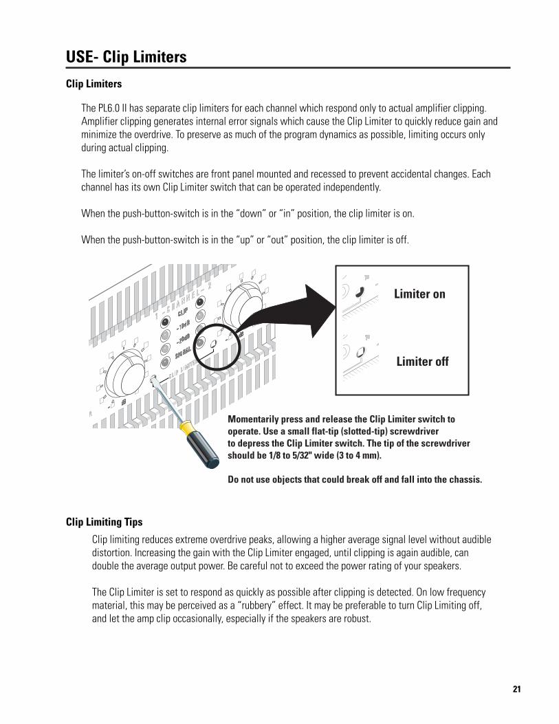
Clip Limiters
The PL6.0 II has separate clip limiters for each channel which respond only to actual amplifier clipping.Amplifier clipping generates internal error signals which cause the Clip Limiter to quickly reduce gain andminimize the overdrive. To preserve as much of the program dynamics as possible, limiting occurs onlyduring actual clipping.
The limiter’s on-off switches are front panel mounted and recessed to prevent accidental changes. Eachchannel has its own Clip Limiter switch that can be operated independently.
When the push-button-switch is in the “down” or “in” position, the clip limiter is on.
When the push-button-switch is in the “up” or “out” position, the clip limiter is off.
Clip Limiting Tips
Clip limiting reduces extreme overdrive peaks, allowing a higher average signal level without audibledistortion. Increasing the gain with the Clip Limiter engaged, until clipping is again audible, candouble the average output power. Be careful not to exceed the power rating of your speakers.
The Clip Limiter is set to respond as quickly as possible after clipping is detected. On low frequencymaterial, this may be perceived as a “rubbery” effect. It may be preferable to turn Clip Limiting off,and let the amp clip occasionally, especially if the speakers are robust.
22
TROUBLESHOOTING
The amplifier “cuts-out” when I really crank it up (intermittent operation)-
• Make sure the AC power source is rated for the required current! Use only 10-gaugeheavy-duty extension cords.
• If the AC power source is “sagging” (or drooping) under heavy load, the circuit isoverloaded or has other fundamental problems. Use another circuit or have the circuitchecked by a licensed, professional electrician.
• Do not use multiple PL6.0 II’s from the same AC power circuit branch. Momentary, peakcurrent from the AC line can easily exceed 50 Amps per amplifier. While this is well withinthe limits of 30 Amp (continuous) circuits, additional amplifier’s could overload one circuitbranch. Always consult a licensed, professional electrician for verification of proper ACpower distribution in high-power systems.
Can I use some sort of adapter on the power cord so that I can use “regular” outlets?-
• QSC Audio Products strongly discourages ANY changes in the AC power connections.Use only NEMA L5-30, 120V, 30 Ampere twist-lock connectors or the 240V cordsetsupplied with the amplifier. All supply circuits and AC power receptacles should be ratedfor voltage and current printed on the serial number plate.
• Unreliable and potentially dangerous conditions could result from using this productwith improperly rated AC supply circuits. Always consult a licensed, professionalelectrician for verification of proper AC power distribution in high-power systems.
• In emergencies, 15A adaptors can be used if full operating levels are avoided.
The amplifier won’t turn on when the Power switch is operated-
• Verify AC power source is providing required voltage.
• Check each end of the power cord. The twist-lock or IEC-type connectors need to beproperly inserted. Inspect the cord for damage. If any damage is found, replace the cordimmediately.
• If using the DataPort and QSC amplifier network control applications, the amplifiercould be in STANDBY mode. Check with the system operator to place the amplifiers inPOWER ON mode. If required, you can check this by temporarily disconnecting theDataPort cables to each Processor; if the amplifier powers up, then the amplifier networkcontrol was forcing the amp to be in STANDBY mode.
• If using the rear panel Power Supply Control connections, be sure the control’s contactsare open.

23
TROUBLESHOOTING
I am trying to use QSC’s DSP-3 or DSP-4 signal processor, but it doesn’t power up when the amp is turned on.What’s wrong?-
• Nothing. The PL6.0 II does not supply the required power to the DSP-3 or DSP-4module.
• An accessory AC adaptor (wall wart) will be required for the DSP-3 or DSP-4. ContactQSC Technical Services for details.
• Make sure the DataPort cable between the amp and the DSP module has pin #9removed from either end. See DSP module documentation for details.
I am using the amp for a subwoofer application and it sounds “rubbery”, what’s up?-
• Verify that the Clip Limiters are OFF. See page 21.
• The Clip Limiter is set to respond as quickly as possible after clipping is detected. Onlow frequency material, this may be perceived as a “rubbery” effect. It may be preferableto turn Clip Limiting off, and let the amp clip occasionally, especially if the speakers arerobust.
24
SPECIFICATIONS- PowerLight 6.0 II Electrical Data
Note: Specifications are subject to change without notice.
Output Circuit Type quasi-complementary MOSFET output with multi-step high efficiency circuit
Output Power in watts20 Hz to 20 kHz 8 ohms per channel 1150 at 0.1% THD
4 ohms per channel 2050 at 0.1% THD2 ohms per channel 3250 at 0.1% THD
EIA: 1 kHz @ 1% THD 8 ohms per channel 13004 ohms per channel 22002 ohms per channel 3500
Bridged Mode 16 ohms, 1 kHz, 1% THD 26008 ohms, 1 kHz, 1% THD 44004 ohms, 1 kHz, 1% THD 7000
Dynamic Headroom at 4 ohms 0.77 dB
Distortion, THD20 Hz to 20 kHz <0.06%: 8, 4, and 2 ohms at 10 dB below rated power20 Hz to 2 kHz <0.02%: 1150 watts at 8 ohms, 2050 watts at 4 ohms, 3250 watts at 2 ohm
Frequency response at 10 dB below rated power20 Hz to 20 kHz ±0.15 dB2 Hz to 50 kHz ±3.0 dB
Damping Factor >2000 at 1 kHz and below
Noise (unweighted) 107 dB below rated output from 20 Hz to 20 kHz
Voltage Gain 40x (32 dB)
Input Sensitivity 2.4 Vrms (+9.4 dBu) for rated power into 8 ohms2.3 Vrms (+9.5 dBu) for rated power into 4 ohms
Input Impedance 20 k ohm balanced, 10 k ohm unbalanced
Controls AC power switch, Mode switch, Gain controls, Clip Limiter switches
Connectors Inputs: “combo” and terminal-blockOutputs: binding posts, 60 amp rated, recommend no banana plug usage
Speakon outputs, 1 per channel for Stereo and Parallel operation onlyPower Supply Control connector: 2-pin terminal block connector
LED Indicators Power supply section: Power “on”- red; Standby- yellow; Protect, red (1 LED for each channel)Signal indicator section: Signal- green; -20 dB, yellow; -10 dB, yellow; Clip, red (1 for each channel)
25
APPENDIX-DataPort Pinout
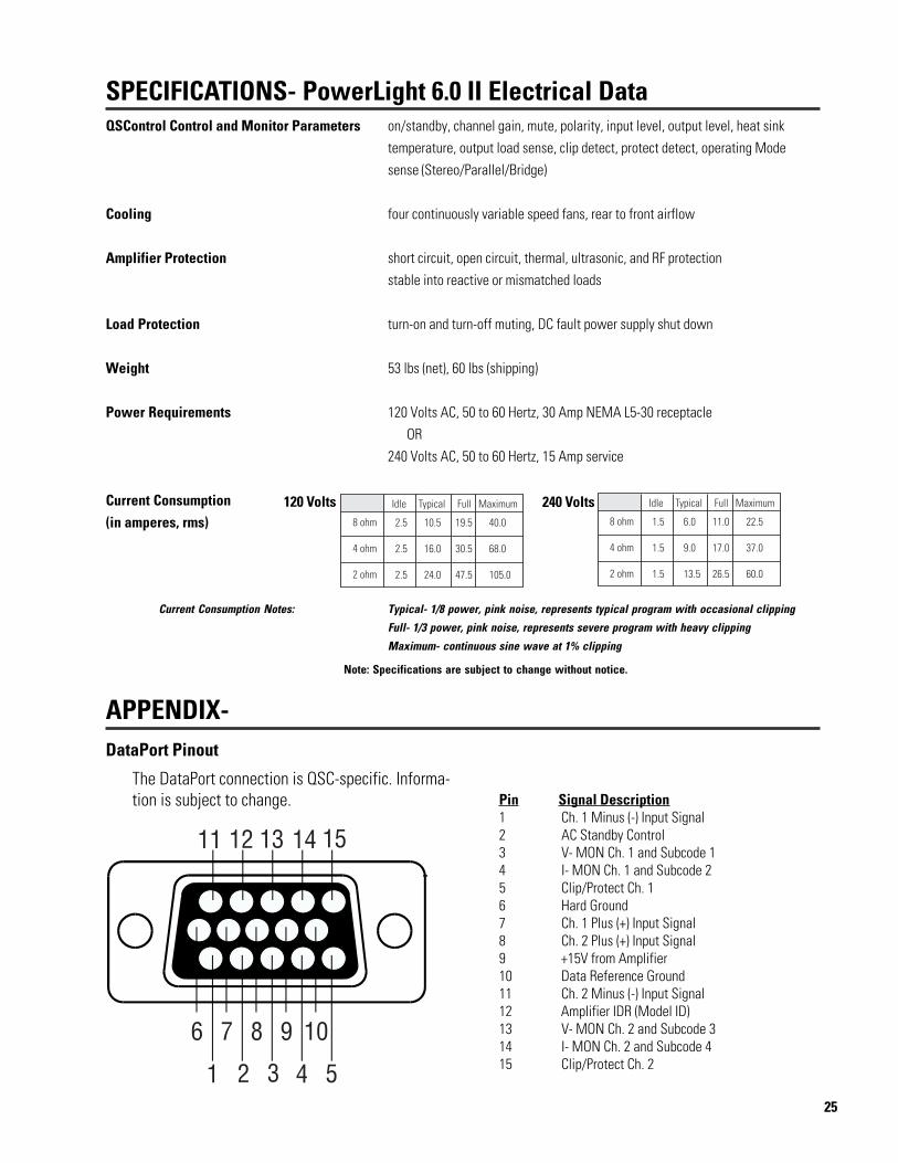
The DataPort connection is QSC-specific. Informa-tion is subject to change.
SPECIFICATIONS- PowerLight 6.0 II Electrical DataQSControl Control and Monitor Parameters on/standby, channel gain, mute, polarity, input level, output level, heat sink
temperature, output load sense, clip detect, protect detect, operating Modesense (Stereo/Parallel/Bridge)
Cooling four continuously variable speed fans, rear to front airflow
Amplifier Protection short circuit, open circuit, thermal, ultrasonic, and RF protectionstable into reactive or mismatched loads
Load Protection turn-on and turn-off muting, DC fault power supply shut down
Weight 53 lbs (net), 60 lbs (shipping)
Power Requirements 120 Volts AC, 50 to 60 Hertz, 30 Amp NEMA L5-30 receptacle OR240 Volts AC, 50 to 60 Hertz, 15 Amp service
Current Consumption(in amperes, rms)
Current Consumption Notes: Typical- 1/8 power, pink noise, represents typical program with occasional clipping
Full- 1/3 power, pink noise, represents severe program with heavy clipping
Maximum- continuous sine wave at 1% clipping
Note: Specifications are subject to change without notice.
Pin Signal Description1 Ch. 1 Minus (-) Input Signal2 AC Standby Control3 V- MON Ch. 1 and Subcode 14 I- MON Ch. 1 and Subcode 25 Clip/Protect Ch. 16 Hard Ground7 Ch. 1 Plus (+) Input Signal8 Ch. 2 Plus (+) Input Signal9 +15V from Amplifier10 Data Reference Ground11 Ch. 2 Minus (-) Input Signal12 Amplifier IDR (Model ID)13 V- MON Ch. 2 and Subcode 314 I- MON Ch. 2 and Subcode 415 Clip/Protect Ch. 2
120 Volts 240 Volts
26
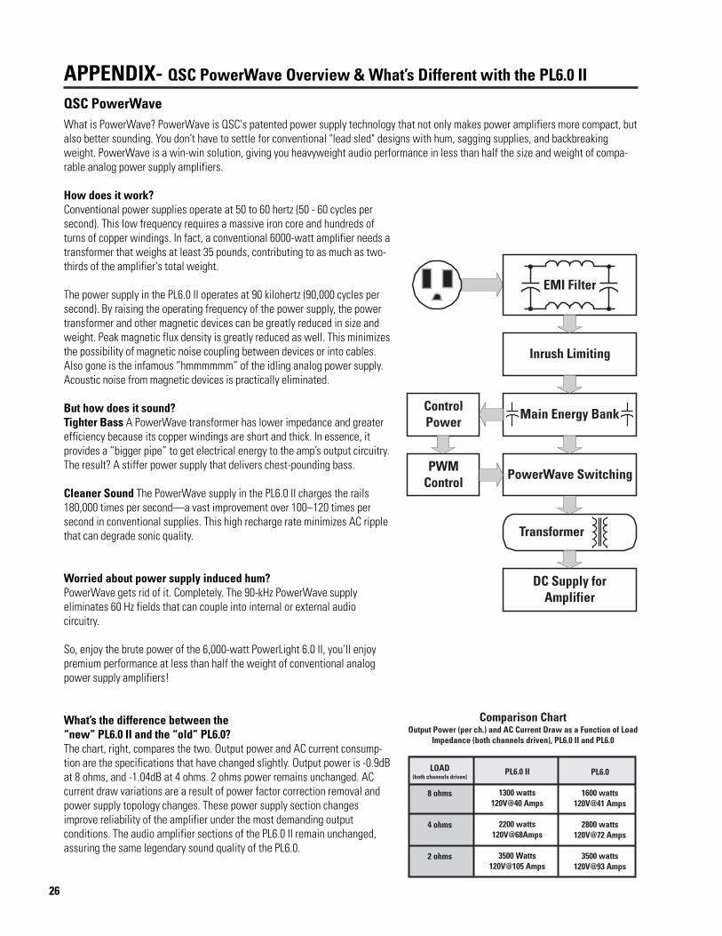
What is PowerWave? PowerWave is QSC's patented power supply technology that not only makes power amplifiers more compact, butalso better sounding. You don’t have to settle for conventional "lead sled" designs with hum, sagging supplies, and backbreakingweight. PowerWave is a win-win solution, giving you heavyweight audio performance in less than half the size and weight of compa-rable analog power supply amplifiers.
How does it work?Conventional power supplies operate at 50 to 60 hertz (50 - 60 cycles persecond). This low frequency requires a massive iron core and hundreds ofturns of copper windings. In fact, a conventional 6000-watt amplifier needs atransformer that weighs at least 35 pounds, contributing to as much as two-thirds of the amplifier's total weight.
The power supply in the PL6.0 II operates at 90 kilohertz (90,000 cycles persecond). By raising the operating frequency of the power supply, the powertransformer and other magnetic devices can be greatly reduced in size andweight. Peak magnetic flux density is greatly reduced as well. This minimizesthe possibility of magnetic noise coupling between devices or into cables.Also gone is the infamous “hmmmmmm” of the idling analog power supply.Acoustic noise from magnetic devices is practically eliminated.
But how does it sound?Tighter Bass A PowerWave transformer has lower impedance and greaterefficiency because its copper windings are short and thick. In essence, itprovides a “bigger pipe” to get electrical energy to the amp’s output circuitry.The result? A stiffer power supply that delivers chest-pounding bass.
Cleaner Sound The PowerWave supply in the PL6.0 II charges the rails180,000 times per second—a vast improvement over 100–120 times persecond in conventional supplies. This high recharge rate minimizes AC ripplethat can degrade sonic quality.
Worried about power supply induced hum?PowerWave gets rid of it. Completely. The 90-kHz PowerWave supplyeliminates 60 Hz fields that can couple into internal or external audiocircuitry.
So, enjoy the brute power of the 6,000-watt PowerLight 6.0 II, you’ll enjoypremium performance at less than half the weight of conventional analogpower supply amplifiers!
What’s the difference between the“new” PL6.0 II and the “old” PL6.0?The chart, right, compares the two. Output power and AC current consump-tion are the specifications that have changed slightly. Output power is -0.9dBat 8 ohms, and -1.04dB at 4 ohms. 2 ohms power remains unchanged. ACcurrent draw variations are a result of power factor correction removal andpower supply topology changes. These power supply section changesimprove reliability of the amplifier under the most demanding outputconditions. The audio amplifier sections of the PL6.0 II remain unchanged,assuring the same legendary sound quality of the PL6.0.
APPENDIX- QSC PowerWave Overview & What’s Different with the PL6.0 II
QSC PowerWave
27
Disclaimer
QSC Audio Products, Inc. is not liable for any damage to speakers, or any other equipment that is caused by negligence orimproper installation and/or use of this amplifier product.
Product Warranty
QSC Audio Products, Inc. (“QSC”) guarantees its products to be free from defective material and / or workmanship for a period ofthree (3) years from date of sale, and will replace defective parts and repair malfunctioning products under this warranty when thedefect occurs under normal installation and use - provided the unit is returned to our factory or one of our authorized servicestations via prepaid transportation with a copy of proof of purchase (i.e., sales receipt). This warranty provides that the examina-tion of the return product must indicate, in our judgment, a manufacturing defect. This warranty does not extend to any productwhich has been subjected to misuse, neglect, accident, improper installation, or where the date code has been removed ordefaced. QSC shall not be liable for incidental and/or consequential damages. This warranty gives you specific legal rights, andyou may also have other rights which vary from state to state. This limited warranty is freely transferable during the term of thewarranty period.
(USA only; other countries, see your dealer or distributor)
Mailing address / Adresse postale / Postanschrift / Dirección postal: QSC Audio Products, Inc.
1675 MacArthur BoulevardCosta Mesa, CA 92626-1468 USA
Telephone Numbers / Numéros de téléphone / Telefonnummern / Números de teléfono:
Main Number / Numéro principal / Hauptnummer / Número principal +(714) 754-6175
Sales Direct Line / Ligne directe ventes / Verkauf-Direkt / Línea directo ventas +(714) 957-7100
Sales & Marketing / Ventes & marketing / Verkauf u. Marketing / Ventas y marketing (800) 854-4079 (toll-free in U.S.A. only)
(sans frais aux É-U seulement)
(zollfrei nur beim USA)
(sin costo en EE. UU. solamente)
Technical Services Group / Service à la clientèle / Kundendienst / Servicio a la clientela +(714) 957-7150(800) 772-2834 (toll-free in U.S.A. only)
(sans frais aux É-U seulement)
(zollfrei nur beim USA)
(sin costo en EE. UU. solamente)
Facsimile Numbers / Numéros de télécopieur / Telefaxnummern / Número de FAX:Sales & Marketing FAX / Télécopie ventes & marketing / Telefax der Verkauf u. Marketing / FAX ventas y marketing
+(714) 754-6174
Customer Service FAX / Télécopie service à la clientèle / Kundendienst-Telefax / FAX servicio a la clientela+(714) 754-6173
World Wide Web: www.qscaudio.com
E-mail: [email protected]
WARRANTY
HOW TO CONTACT QSC AUDIO PRODUCTS
WARRANTY INFORMATION & HOW TO CONTACT QSC

28
QSC Audio Products, Inc. 1675 MacArthur Boulevard Costa Mesa, California 92626 USA“QSC” and the QSC logo are registered with the U.S. Patent and Trademark Office.
©2002 QSC Audio Products, Inc.


![CONTENTS CONTACT INFORMATION MISCELLANEOUS · PDF file[Speaker bridge is in Proscenium] ... 400amp 3 phase 4 wire + ground ... - 1 – QSC Power Amplifier -1](https://img.pdfslide.us/doc/110x75/5ab884a57f8b9ab62f8cb7d2/contents-contact-information-miscellaneous-speaker-bridge-is-in-proscenium-.jpg)