Embed Size (px)
Citation preview
TBS VENDETTA FPV Racer Revision 2016-09-24 Full carbon fiber ready‐to‐fly 240‐size fpv racer
Full carbon fiber monocoque, quick swap arms, solder-free repairs, ready-to-fly as 240-size fpv racer, for 5"
props. But it doesn't stop there! Sporting the brand new TBS Triumph antenna in combination with the TBS
CORE Pro and TBS Unify Pro, the TBS Vendetta allows you to configure every parameter of your FPV racer via
R/C stick commands! Each drone comes tuned and test-flown by our professional tuning experts. Install a
receiver, strap on a 4S battery and the TBS VENDETTA will tear a hole into the sky, and you're coming along
for the ride!
Key features
● Ready-to-fly full carbon fiber 240-size fpv racer
● Quick-replace 3.5mm carbon fiber arms, MT30 connectors
● Cobra CM2204 2300kV Motors, HQ 5x4x3 Props
● TBS POWERCUBE with fastest F3 board available, 2-6S capable Bulletproof 30/50A ESCs
● Compatible with PPM, SBUS, XBUS, Spektrum R/C systems
● Fully configurable via OSD, no PC required
● GoPro 3/4 and Mobius / Runcam mount included, both 10° and 30° variations
● Lost model alarm, adjustable camera angle
● 410g weight excl. battery and HD camera
1
Table of content
Attention
Disclaimer
Overview
Quick Start Guide - BNF set
Setup
Opening the frame
Installing radio receiver
Installing video antenna
Binding radio receiver and system configuration
Adjusting camera tilt angle
Mounting receiver antennas
Attaching frame arms
Putting on propellers
Mounting battery
Mounting HD camera
Flight modes
Rear LED status lights
Repairing arms
Configuration
OSD Boot up
Initial R/C calibration
Entering OSD configuration menu
Changing VTX channel
Changing VTX power level
COLIBRI FC configuration
COLIBRI FC receiver setup
Firmware upgrade
Installing TBS Agent
Updating CORE PRO
Updating COLIBRI FC firmware
Good practices
2
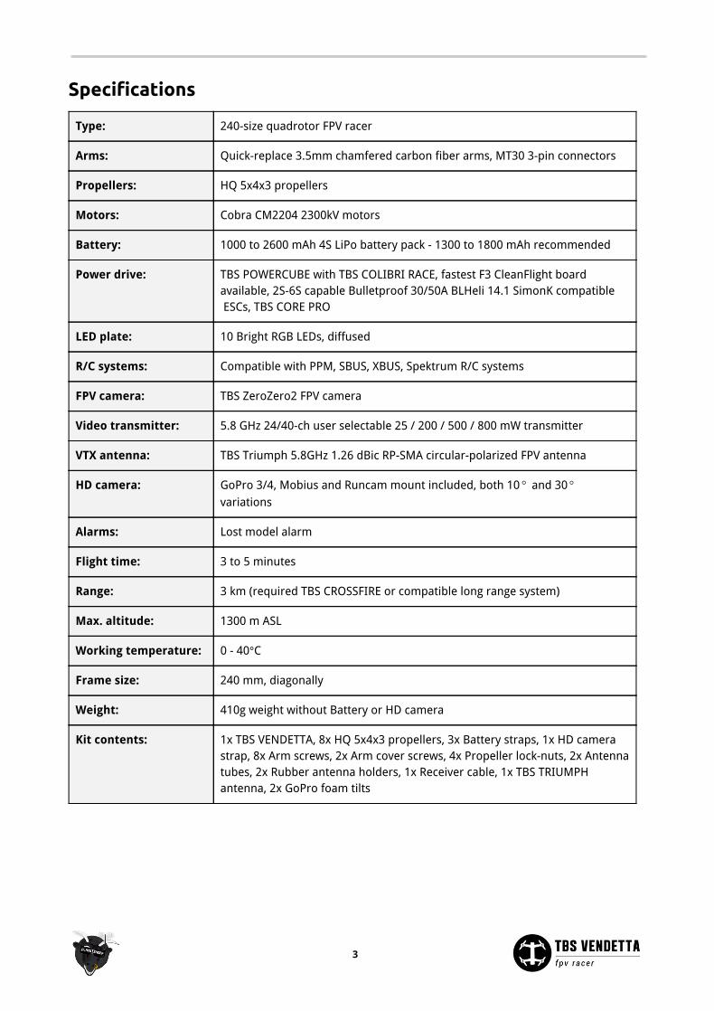
Specifications
Type: 240-size quadrotor FPV racer
Arms: Quick-replace 3.5mm chamfered carbon fiber arms, MT30 3-pin connectors
Propellers: HQ 5x4x3 propellers
Motors: Cobra CM2204 2300kV motors
Battery: 1000 to 2600 mAh 4S LiPo battery pack - 1300 to 1800 mAh recommended
Power drive: TBS POWERCUBE with TBS COLIBRI RACE, fastest F3 CleanFlight board available, 2S-6S capable Bulletproof 30/50A BLHeli 14.1 SimonK compatible ESCs, TBS CORE PRO
LED plate: 10 Bright RGB LEDs, diffused
R/C systems: Compatible with PPM, SBUS, XBUS, Spektrum R/C systems
FPV camera: TBS ZeroZero2 FPV camera
Video transmitter: 5.8 GHz 24/40-ch user selectable 25 / 200 / 500 / 800 mW transmitter
VTX antenna: TBS Triumph 5.8GHz 1.26 dBic RP-SMA circular-polarized FPV antenna
HD camera: GoPro 3/4, Mobius and Runcam mount included, both 10 and 30° ° variations
Alarms: Lost model alarm
Flight time: 3 to 5 minutes
Range: 3 km (required TBS CROSSFIRE or compatible long range system)
Max. altitude: 1300 m ASL
Working temperature: 0 - 40°C
Frame size: 240 mm, diagonally
Weight: 410g weight without Battery or HD camera
Kit contents: 1x TBS VENDETTA, 8x HQ 5x4x3 propellers, 3x Battery straps, 1x HD camera strap, 8x Arm screws, 2x Arm cover screws, 4x Propeller lock-nuts, 2x Antenna tubes, 2x Rubber antenna holders, 1x Receiver cable, 1x TBS TRIUMPH antenna, 2x GoPro foam tilts
3
Attention Thank you for buying a TBS product! The TBS VENDETTA is a new racing multirotor aircraft from Team
BlackSheep (TBS). It features the best design practices available on the market to date.
A general rule for RC aircrafts is that they must be controlled always under sight of view, check your RC
regulation to keep up to date with regulations.
Please read this manual carefully before assembling and flying your new TBS VENDETTA quadcopter. Keep
this manual for future reference regarding tuning and maintenance.
Disclaimer
Our request to you; the aircraft may not be used to infringe on people's right to privacy. We have designed a
toy with mind blowing capabilities. It is your responsibility to use it reasonably and according to your
experience level. Use common sense. Fly safe. You are on your own. TBS has no liability for use of this
aircraft.
● Locate an appropriate flying location
● Obtain the assistance of an experienced pilot
● Practice safe and responsible operation
● Always be aware of the rotating blades
● Prevent moisture
● Keep away from heat or excessive amounts of sunlight
4
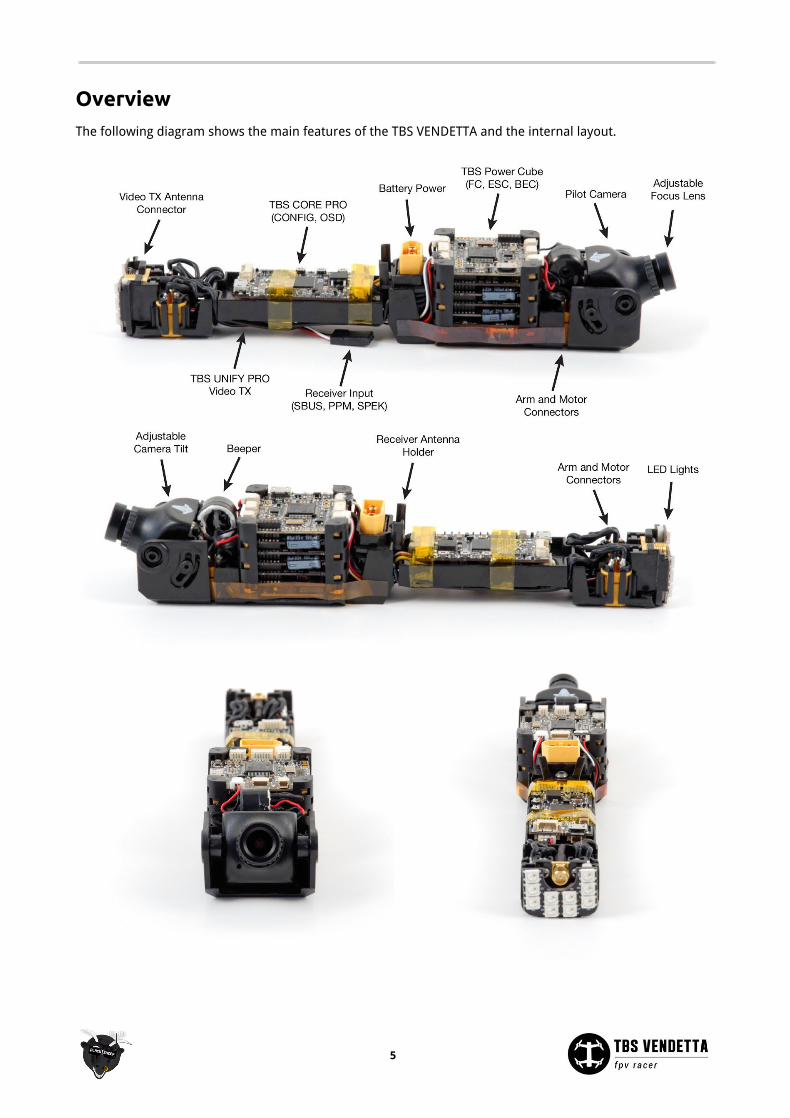
Overview The following diagram shows the main features of the TBS VENDETTA and the internal layout.
5
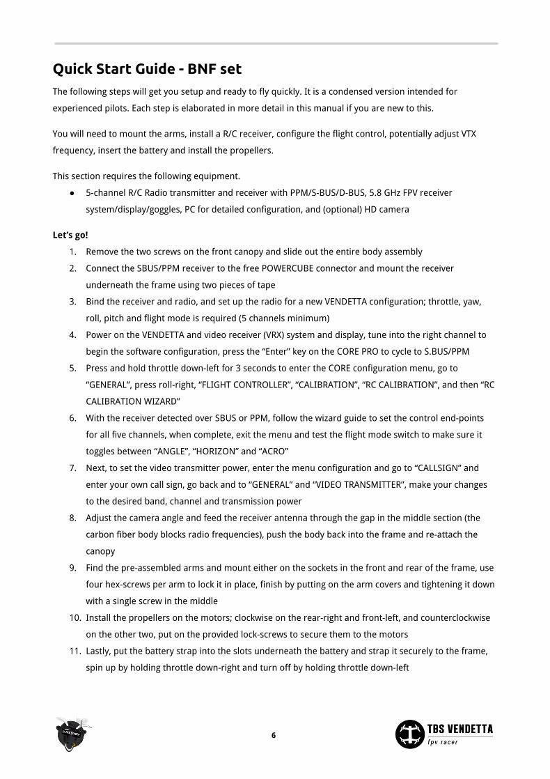
Quick Start Guide - BNF set The following steps will get you setup and ready to fly quickly. It is a condensed version intended for
experienced pilots. Each step is elaborated in more detail in this manual if you are new to this.
You will need to mount the arms, install a R/C receiver, configure the flight control, potentially adjust VTX
frequency, insert the battery and install the propellers.
This section requires the following equipment.
● 5-channel R/C Radio transmitter and receiver with PPM/S-BUS/D-BUS, 5.8 GHz FPV receiver
system/display/goggles, PC for detailed configuration, and (optional) HD camera
Let’s go!
1. Remove the two screws on the front canopy and slide out the entire body assembly
2. Connect the SBUS/PPM receiver to the free POWERCUBE connector and mount the receiver
underneath the frame using two pieces of tape
3. Bind the receiver and radio, and set up the radio for a new VENDETTA configuration; throttle, yaw,
roll, pitch and flight mode is required (5 channels minimum)
4. Power on the VENDETTA and video receiver (VRX) system and display, tune into the right channel to
begin the software configuration, press the “Enter” key on the CORE PRO to cycle to S.BUS/PPM
5. Press and hold throttle down-left for 3 seconds to enter the CORE configuration menu, go to
“GENERAL”, press roll-right, “FLIGHT CONTROLLER”, “CALIBRATION”, “RC CALIBRATION”, and then “RC
CALIBRATION WIZARD”
6. With the receiver detected over SBUS or PPM, follow the wizard guide to set the control end-points
for all five channels, when complete, exit the menu and test the flight mode switch to make sure it
toggles between “ANGLE”, “HORIZON” and “ACRO”
7. Next, to set the video transmitter power, enter the menu configuration and go to “CALLSIGN” and
enter your own call sign, go back and to “GENERAL” and “VIDEO TRANSMITTER”, make your changes
to the desired band, channel and transmission power
8. Adjust the camera angle and feed the receiver antenna through the gap in the middle section (the
carbon fiber body blocks radio frequencies), push the body back into the frame and re-attach the
canopy
9. Find the pre-assembled arms and mount either on the sockets in the front and rear of the frame, use
four hex-screws per arm to lock it in place, finish by putting on the arm covers and tightening it down
with a single screw in the middle
10. Install the propellers on the motors; clockwise on the rear-right and front-left, and counterclockwise
on the other two, put on the provided lock-screws to secure them to the motors
11. Lastly, put the battery strap into the slots underneath the battery and strap it securely to the frame,
spin up by holding throttle down-right and turn off by holding throttle down-left
6
Setup Getting set up and ready to fly is a quick and simple task, as mostly everything comes pre-built from the TBS
factory. When using TBS equipment, it is mostly plug & play to get ready. Follow these easy steps and you will
be shredding the sky in just a few minutes!
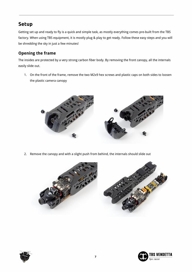
Opening the frame
The insides are protected by a very strong carbon fiber body. By removing the front canopy, all the internals
easily slide out.
1. On the front of the frame, remove the two M2x9 hex screws and plastic caps on both sides to loosen
the plastic camera canopy
2. Remove the canopy and with a slight push from behind, the internals should slide out
7
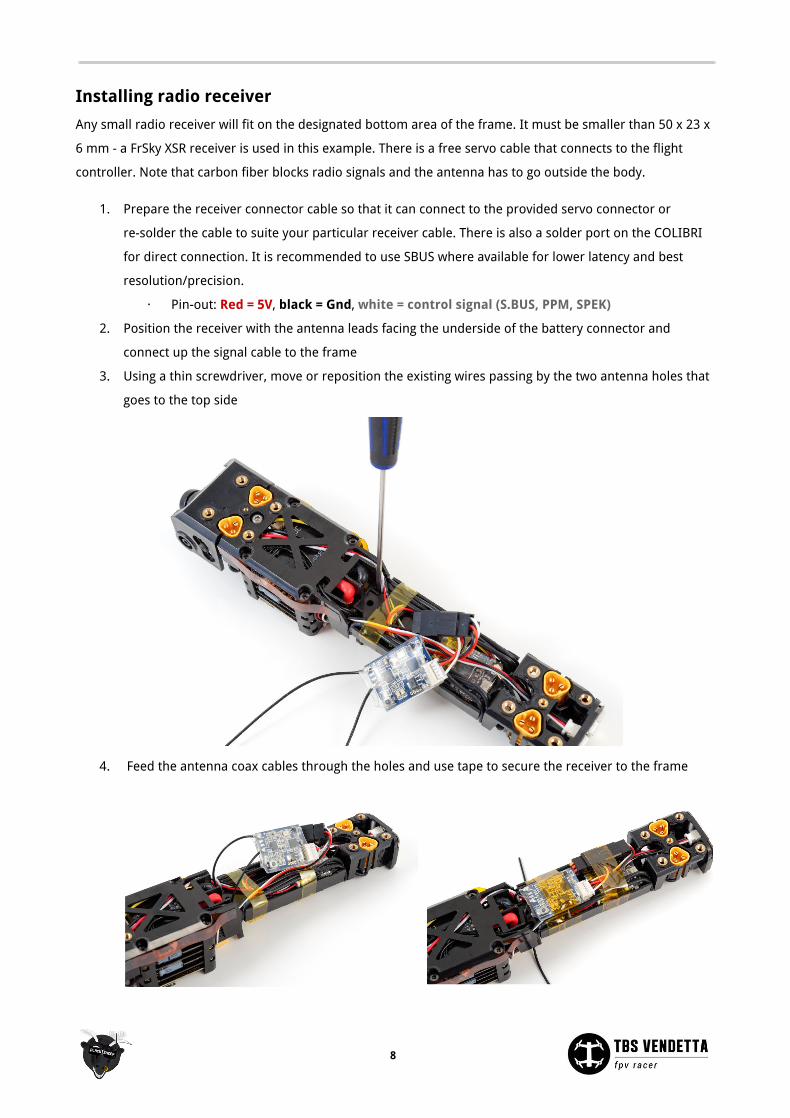
Installing radio receiver
Any small radio receiver will fit on the designated bottom area of the frame. It must be smaller than 50 x 23 x
6 mm - a FrSky XSR receiver is used in this example. There is a free servo cable that connects to the flight
controller. Note that carbon fiber blocks radio signals and the antenna has to go outside the body.
1. Prepare the receiver connector cable so that it can connect to the provided servo connector or
re-solder the cable to suite your particular receiver cable. There is also a solder port on the COLIBRI
for direct connection. It is recommended to use SBUS where available for lower latency and best
resolution/precision.
· Pin-out: Red = 5V, black = Gnd, white = control signal (S.BUS, PPM, SPEK)
2. Position the receiver with the antenna leads facing the underside of the battery connector and
connect up the signal cable to the frame
3. Using a thin screwdriver, move or reposition the existing wires passing by the two antenna holes that
goes to the top side
4. Feed the antenna coax cables through the holes and use tape to secure the receiver to the frame
8
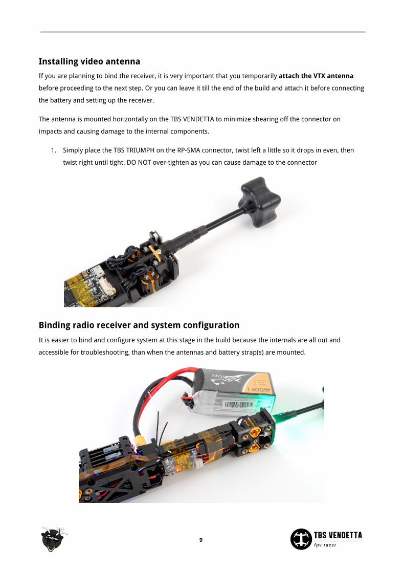
Installing video antenna
If you are planning to bind the receiver, it is very important that you temporarily attach the VTX antenna
before proceeding to the next step. Or you can leave it till the end of the build and attach it before connecting
the battery and setting up the receiver.
The antenna is mounted horizontally on the TBS VENDETTA to minimize shearing off the connector on
impacts and causing damage to the internal components.
1. Simply place the TBS TRIUMPH on the RP-SMA connector, twist left a little so it drops in even, then
twist right until tight. DO NOT over-tighten as you can cause damage to the connector
Binding radio receiver and system configuration
It is easier to bind and configure system at this stage in the build because the internals are all out and
accessible for troubleshooting, than when the antennas and battery strap(s) are mounted.
9
Pairing the radio and receiver is covered in the manufacturer's instructions.
The initial setup of the COLIBRI and CORE requires the FPV video feed to be up on channel Band A CH1 5865
MHz. All the configuration is done via the R/C radio sticks as prompted on the OSD screen.
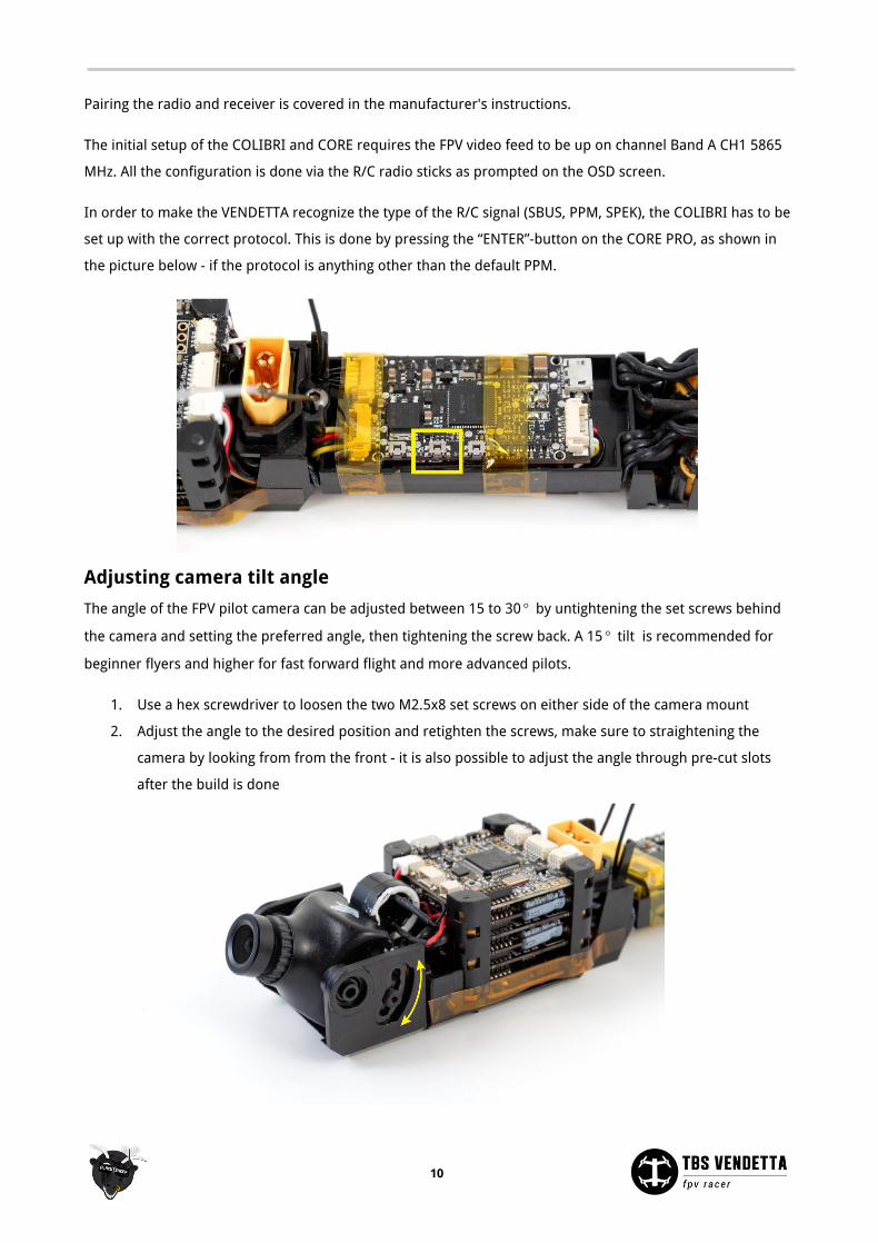
In order to make the VENDETTA recognize the type of the R/C signal (SBUS, PPM, SPEK), the COLIBRI has to be
set up with the correct protocol. This is done by pressing the “ENTER”-button on the CORE PRO, as shown in
the picture below - if the protocol is anything other than the default PPM.
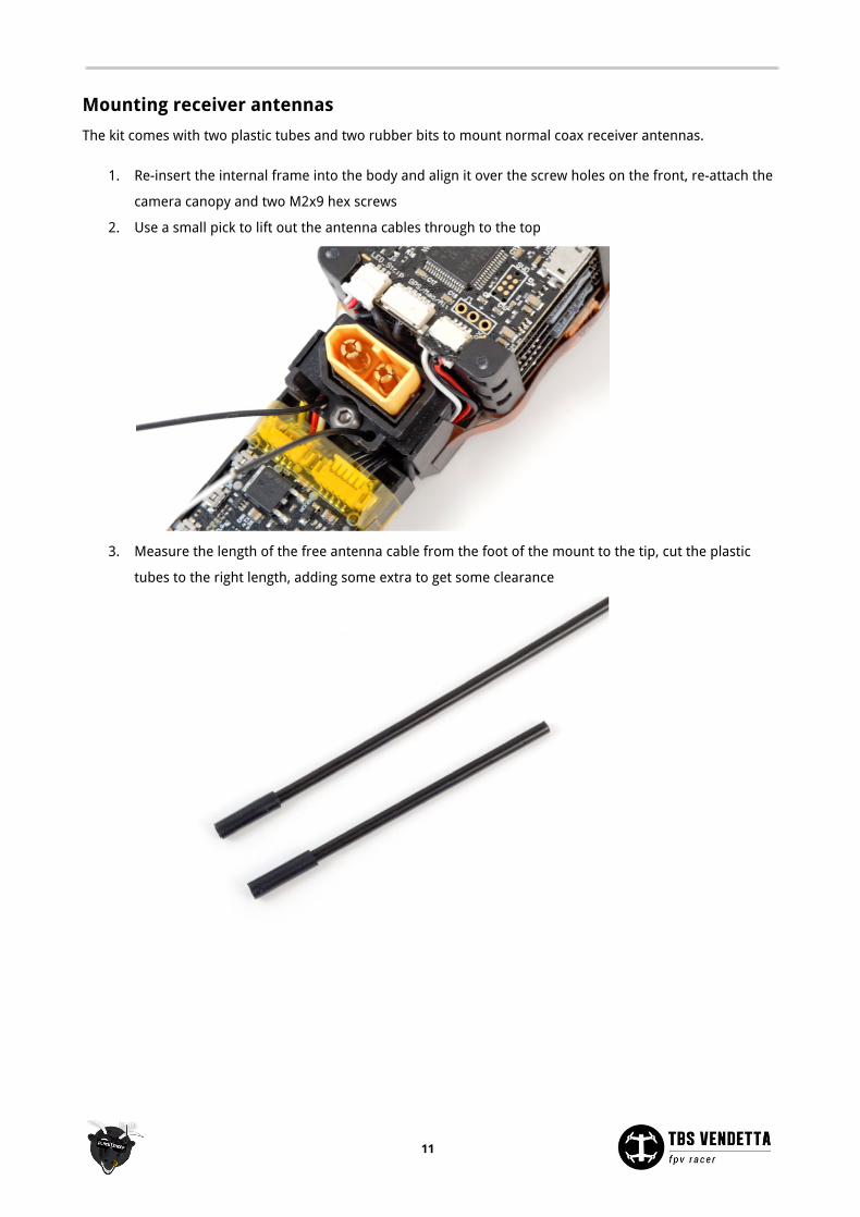
Adjusting camera tilt angle
The angle of the FPV pilot camera can be adjusted between 15 to 30 by untightening the set screws behind°
the camera and setting the preferred angle, then tightening the screw back. A 15 tilt is recommended for°
beginner flyers and higher for fast forward flight and more advanced pilots.
1. Use a hex screwdriver to loosen the two M2.5x8 set screws on either side of the camera mount
2. Adjust the angle to the desired position and retighten the screws, make sure to straightening the
camera by looking from from the front - it is also possible to adjust the angle through pre-cut slots
after the build is done
10
Mounting receiver antennas
The kit comes with two plastic tubes and two rubber bits to mount normal coax receiver antennas.
1. Re-insert the internal frame into the body and align it over the screw holes on the front, re-attach the
camera canopy and two M2x9 hex screws
2. Use a small pick to lift out the antenna cables through to the top
3. Measure the length of the free antenna cable from the foot of the mount to the tip, cut the plastic
tubes to the right length, adding some extra to get some clearance
11
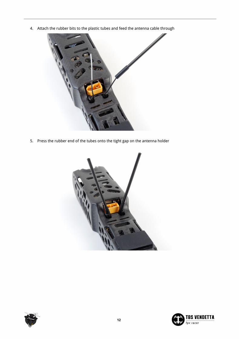
4. Attach the rubber bits to the plastic tubes and feed the antenna cable through
5. Press the rubber end of the tubes onto the tight gap on the antenna holder
12
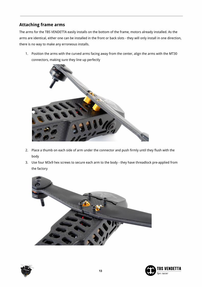
Attaching frame arms
The arms for the TBS VENDETTA easily installs on the bottom of the frame, motors already installed. As the
arms are identical, either one can be installed in the front or back slots - they will only install in one direction,
there is no way to make any erroneous installs.
1. Position the arms with the curved arms facing away from the center, align the arms with the MT30
connectors, making sure they line up perfectly
2. Place a thumb on each side of arm under the connector and push firmly until they flush with the
body
3. Use four M3x9 hex screws to secure each arm to the body - they have threadlock pre-applied from
the factory
13
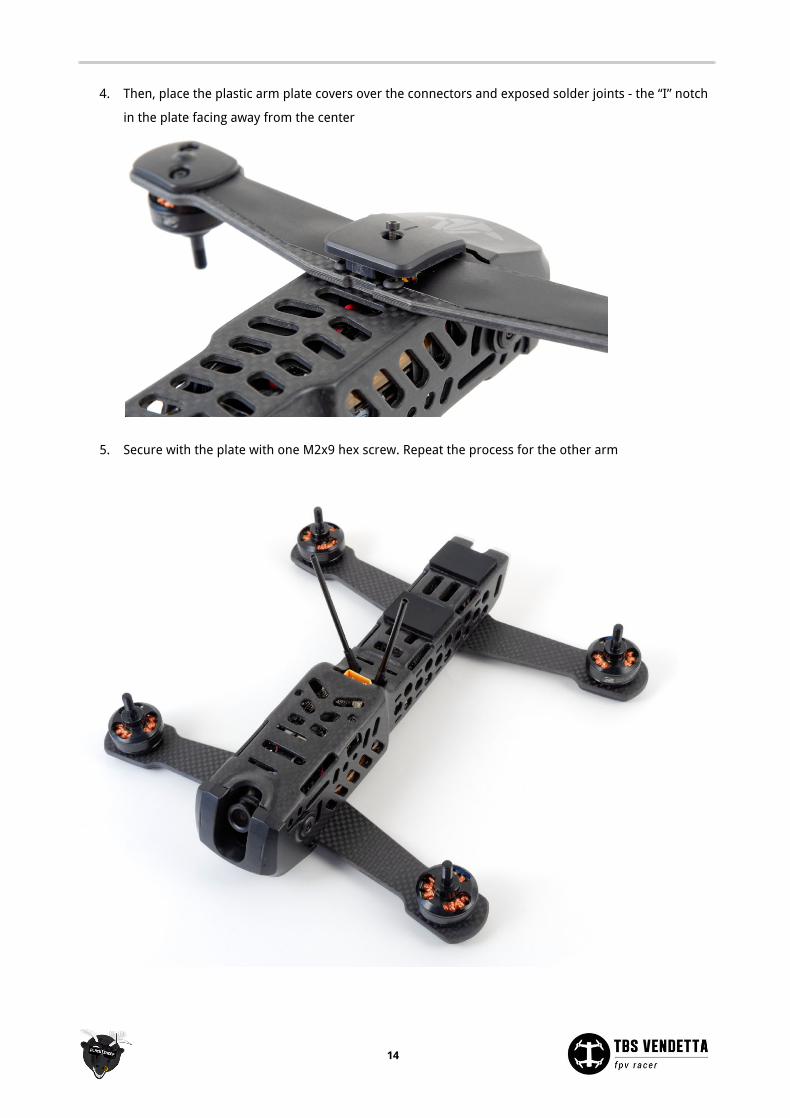
4. Then, place the plastic arm plate covers over the connectors and exposed solder joints - the “I” notch
in the plate facing away from the center
5. Secure with the plate with one M2x9 hex screw. Repeat the process for the other arm
14
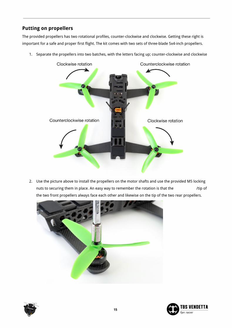
Putting on propellers
The provided propellers has two rotational profiles, counter-clockwise and clockwise. Getting these right is
important for a safe and proper first flight. The kit comes with two sets of three-blade 5x4-inch propellers.
1. Separate the propellers into two batches, with the letters facing up; counter-clockwise and clockwise
2. Use the picture above to install the propellers on the motor shafts and use the provided M5 locking
nuts to securing them in place. An easy way to remember the rotation is that the leading-edge /tip of
the two front propellers always face each other and likewise on the tip of the two rear propellers.
15
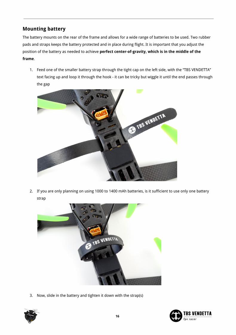
Mounting battery
The battery mounts on the rear of the frame and allows for a wide range of batteries to be used. Two rubber
pads and straps keeps the battery protected and in place during flight. It is important that you adjust the
position of the battery as needed to achieve perfect center-of-gravity, which is in the middle of the
frame.
1. Feed one of the smaller battery strap through the tight cap on the left side, with the “TBS VENDETTA”
text facing up and loop it through the hook - it can be tricky but wiggle it until the end passes through
the gap
2. If you are only planning on using 1000 to 1400 mAh batteries, is it sufficient to use only one battery
strap
3. Now, slide in the battery and tighten it down with the strap(s)
16
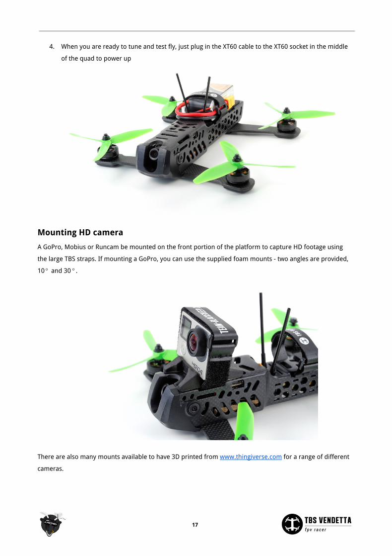
4. When you are ready to tune and test fly, just plug in the XT60 cable to the XT60 socket in the middle
of the quad to power up
Mounting HD camera
A GoPro, Mobius or Runcam be mounted on the front portion of the platform to capture HD footage using
the large TBS straps. If mounting a GoPro, you can use the supplied foam mounts - two angles are provided,
10 and 30 .° °
There are also many mounts available to have 3D printed from www.thingiverse.com for a range of different
cameras.
17
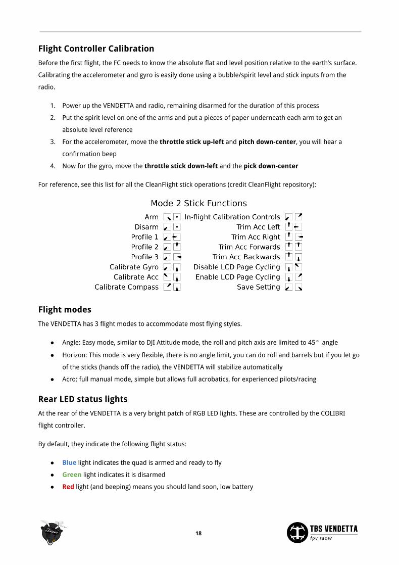
Flight Controller Calibration
Before the first flight, the FC needs to know the absolute flat and level position relative to the earth’s surface.
Calibrating the accelerometer and gyro is easily done using a bubble/spirit level and stick inputs from the
radio.
1. Power up the VENDETTA and radio, remaining disarmed for the duration of this process
2. Put the spirit level on one of the arms and put a pieces of paper underneath each arm to get an
absolute level reference
3. For the accelerometer, move the throttle stick up-left and pitch down-center, you will hear a
confirmation beep
4. Now for the gyro, move the throttle stick down-left and the pick down-center
For reference, see this list for all the CleanFlight stick operations (credit CleanFlight repository):
Flight modes
The VENDETTA has 3 flight modes to accommodate most flying styles.
● Angle: Easy mode, similar to DJI Attitude mode, the roll and pitch axis are limited to 45 angle°
● Horizon: This mode is very flexible, there is no angle limit, you can do roll and barrels but if you let go
of the sticks (hands off the radio), the VENDETTA will stabilize automatically
● Acro: full manual mode, simple but allows full acrobatics, for experienced pilots/racing
Rear LED status lights
At the rear of the VENDETTA is a very bright patch of RGB LED lights. These are controlled by the COLIBRI
flight controller.
By default, they indicate the following flight status:
● Blue light indicates the quad is armed and ready to fly
● Green light indicates it is disarmed
● Red light (and beeping) means you should land soon, low battery
18
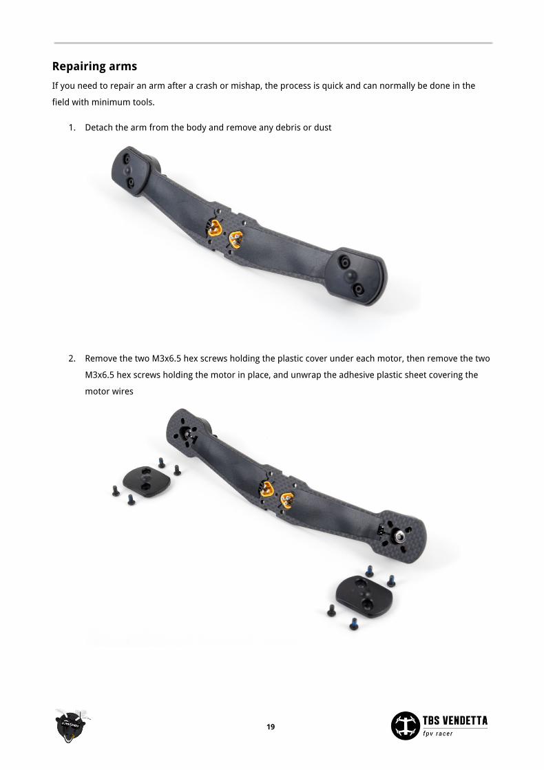
Repairing arms
If you need to repair an arm after a crash or mishap, the process is quick and can normally be done in the
field with minimum tools.
1. Detach the arm from the body and remove any debris or dust
2. Remove the two M3x6.5 hex screws holding the plastic cover under each motor, then remove the two
M3x6.5 hex screws holding the motor in place, and unwrap the adhesive plastic sheet covering the
motor wires
19
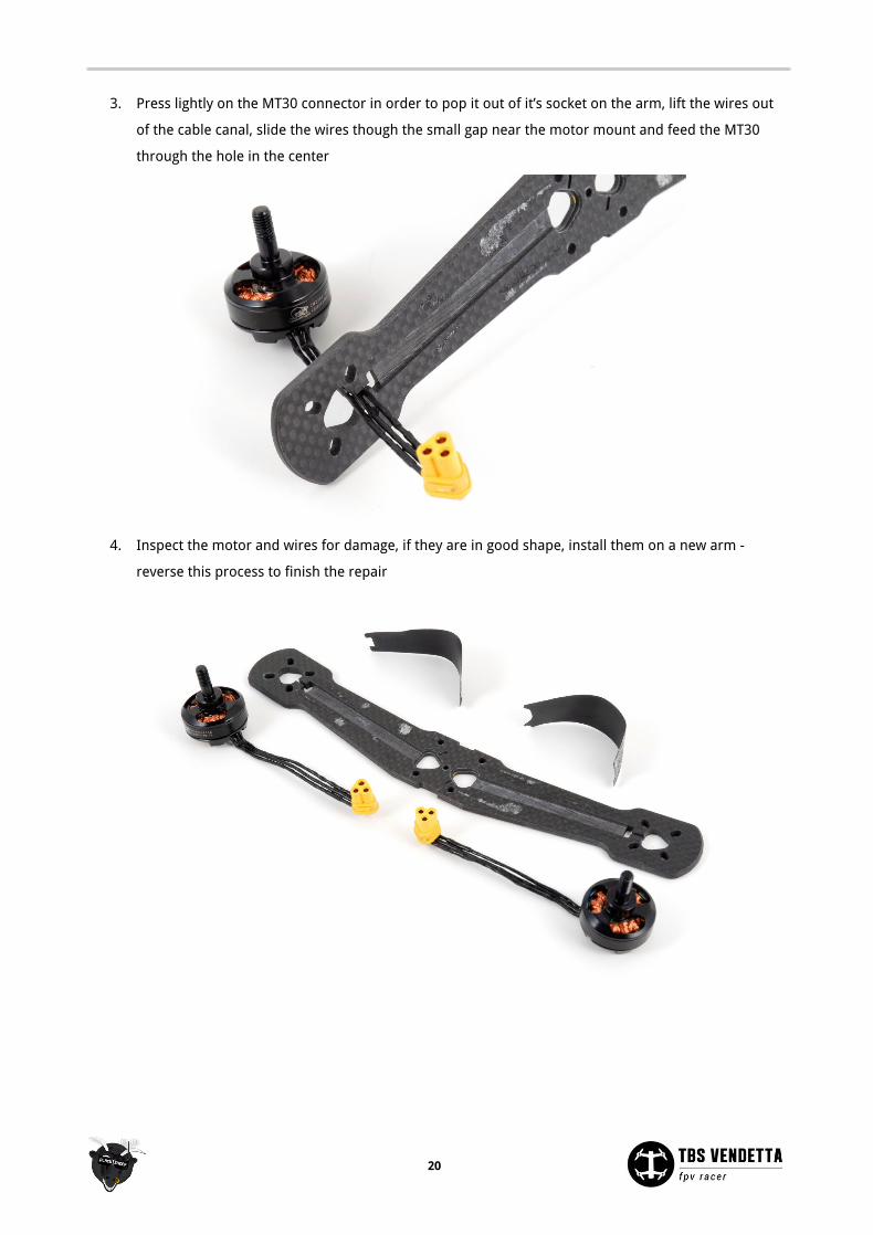
3. Press lightly on the MT30 connector in order to pop it out of it’s socket on the arm, lift the wires out
of the cable canal, slide the wires though the small gap near the motor mount and feed the MT30
through the hole in the center
4. Inspect the motor and wires for damage, if they are in good shape, install them on a new arm -
reverse this process to finish the repair
20
Configuration Changing settings on the TBS VENDETTA (CORE PRO, POWERCUBE, UNIFY PRO) is all done through the video
transmitter and R/C radio inputs, using the sticks to navigate the menus and make changes. Further in-depth
changes of the COLIBRI/CleanFlight flight controller can be made using the USB-interface.
● POWERCUBE manual: http://www.team-blacksheep.com/tbs-powercube-manual.pdf
● CORE PRO manual: http://www.team-blacksheep.com/tbs-core-pro-manual.pdf
● UNIFY PRO manual: http://www.team-blacksheep.com/tbs-unify-pro-5g8-manual.pdf
Warning: remove the propellers before setting up the VENDETTA for the first time!
To enter and navigating the menu system:
● Configuration menu - both sticks on center position, also throttle
● Menu navigation - scroll back and forth using the roll- and pitch-stick
● Select/enter change - left press roll- and pitch-stick
OSD Boot up
When power is applied, the OSD will engage and show you a boot up summary screen. Verify that the
following devices have been detected:
● PCUBE C.SENS - TBS POWERCUBE with current sensor
● COLIBRI FC VX.X - TBS COLIBRI Flight Controller on the POWERCUBE stack
● UNIFY PRO XXXX - TBS UNIFY PRO Video Transmitter, and the frequency it’s on
Initial R/C calibration
If you are an experienced builder and already setup your model in CleanFlight, you can skip this section and
just go into “FLIGHT CONTROLLER” and “READ CLEANFLIGHT RC DATA”. This maps the settings to the CORE
PRO and you are ready to go.
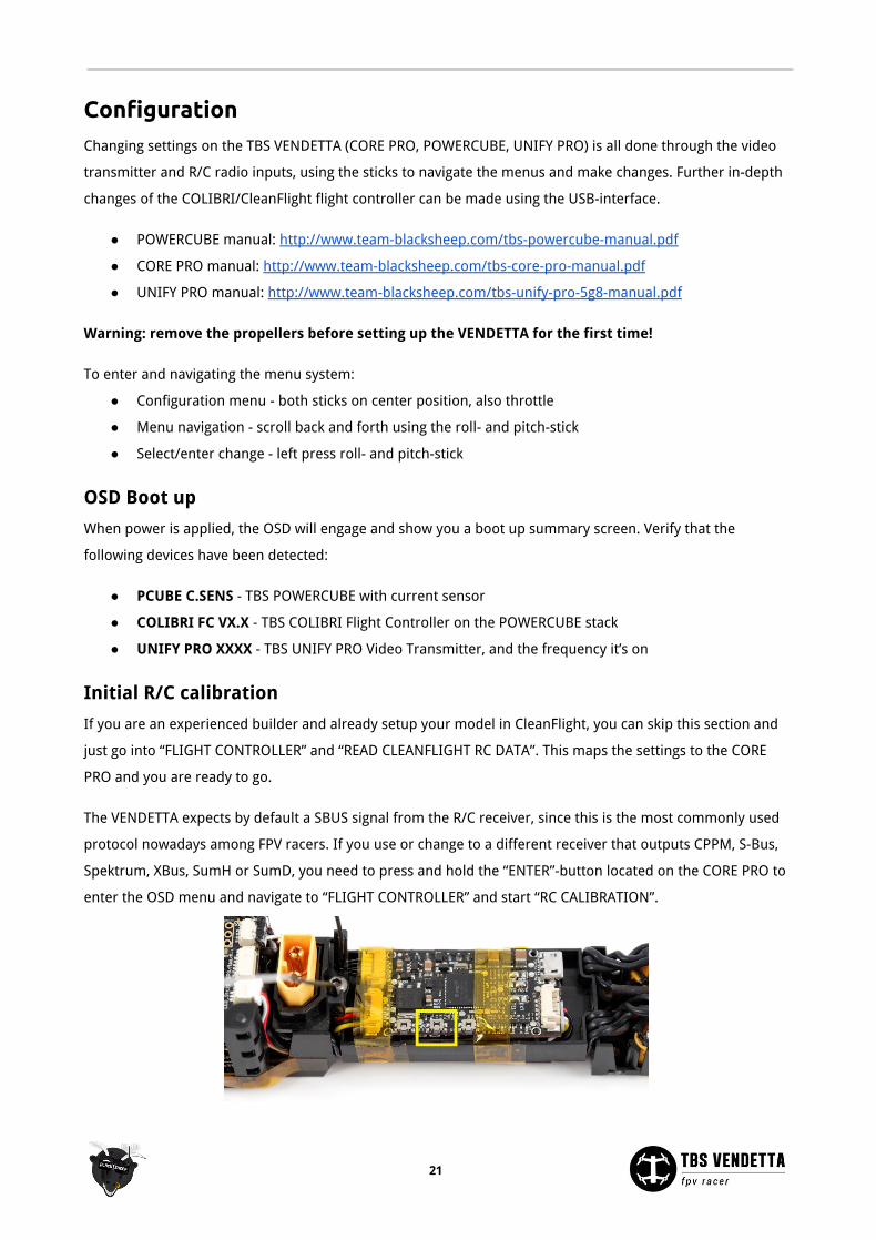
The VENDETTA expects by default a SBUS signal from the R/C receiver, since this is the most commonly used
protocol nowadays among FPV racers. If you use or change to a different receiver that outputs CPPM, S-Bus,
Spektrum, XBus, SumH or SumD, you need to press and hold the “ENTER”-button located on the CORE PRO to
enter the OSD menu and navigate to “FLIGHT CONTROLLER” and start “RC CALIBRATION”.
21
In order to navigate the OSD menus using the radio sticks, the POWERCUBE needs to know which stick
(channel) corresponds to which action (throttle, roll, pitch, yaw).
1. The OSD will say “RC CALIBRATION REQUIRED”, to begin the process, keep both sticks on the radio in
the center position (including throttle).
2. A countdown will start (ignore the “waiting for xxx” message) and the calibration process begin
3. Complete all the steps as described on the display
Entering OSD configuration menu
After the initial calibration is done, the main OSD overlay will show and the VENDETTA is ready to be
configured.
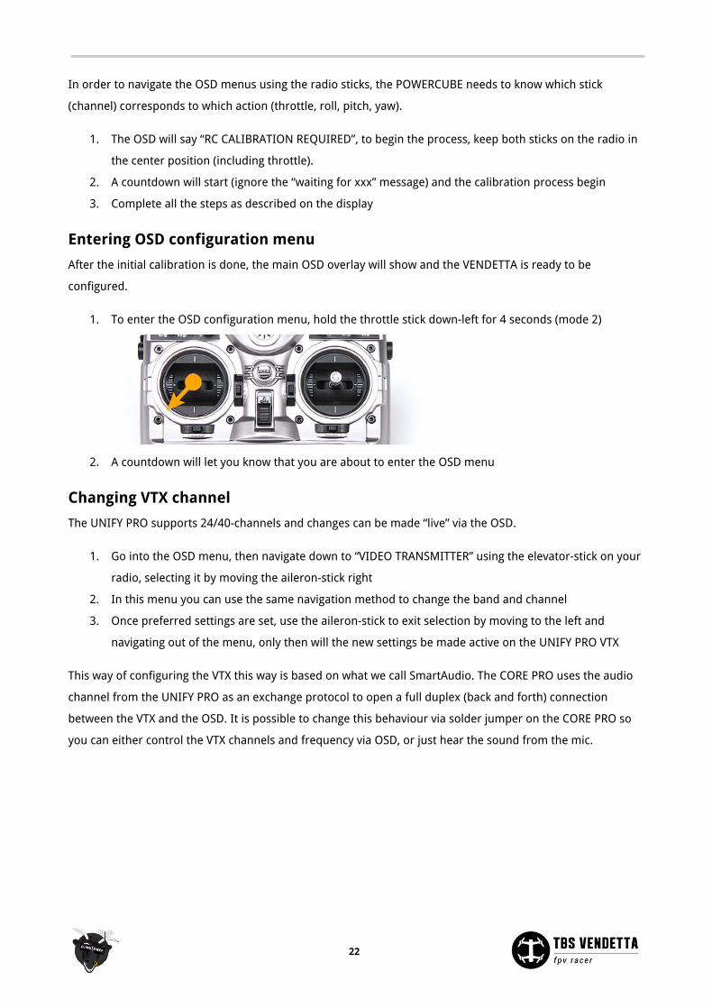
1. To enter the OSD configuration menu, hold the throttle stick down-left for 4 seconds (mode 2)
2. A countdown will let you know that you are about to enter the OSD menu
Changing VTX channel
The UNIFY PRO supports 24/40-channels and changes can be made “live” via the OSD.
1. Go into the OSD menu, then navigate down to “VIDEO TRANSMITTER” using the elevator-stick on your
radio, selecting it by moving the aileron-stick right
2. In this menu you can use the same navigation method to change the band and channel
3. Once preferred settings are set, use the aileron-stick to exit selection by moving to the left and
navigating out of the menu, only then will the new settings be made active on the UNIFY PRO VTX
This way of configuring the VTX this way is based on what we call SmartAudio. The CORE PRO uses the audio
channel from the UNIFY PRO as an exchange protocol to open a full duplex (back and forth) connection
between the VTX and the OSD. It is possible to change this behaviour via solder jumper on the CORE PRO so
you can either control the VTX channels and frequency via OSD, or just hear the sound from the mic.
22
Changing VTX power level
The default VTX power level is 25mW and is fine for all close proximity flight where there is no other FPV
pilots around. In order to unlock higher power levels, you need to change your HAM callsign. Please note
that this requires a HAM license in most countries, which you are obligated to obtain before increasing the
power levels or switching to non-approved frequencies.
1. Go into the OSD and navigate to “VIDEO TRANSMITTER” and “UNLOCK VTX”
2. Change the callsign from the default “TBS”
3. Return to the “VIDEO TRANSMITTER menu and change to “VTX POWER LEVEL”
4. The transmitter power can be changed from 25mW all the way up to 800mW
For racing recommended power is maximum 200mW to avoid interference with other FPV pilots. Power levels
above this is only recommended when flying alone in wide open spaces.
COLIBRI FC configuration
The VENDETTA comes preconfigured with tuned CleanFlight settings and test flown. Changing the essential
flight controller settings such as PID, rates, filters, general settings and accelerometer calibration can be
made using the OSD in the field, or via the USB interface.
Changing settings via OSD:
1. Go to the “FLIGHT CONTROLLER” menu in the OSD
2. Select either “PID”, “RATES”, “GENERAL, “CALIBRATION” or “FILTERS”
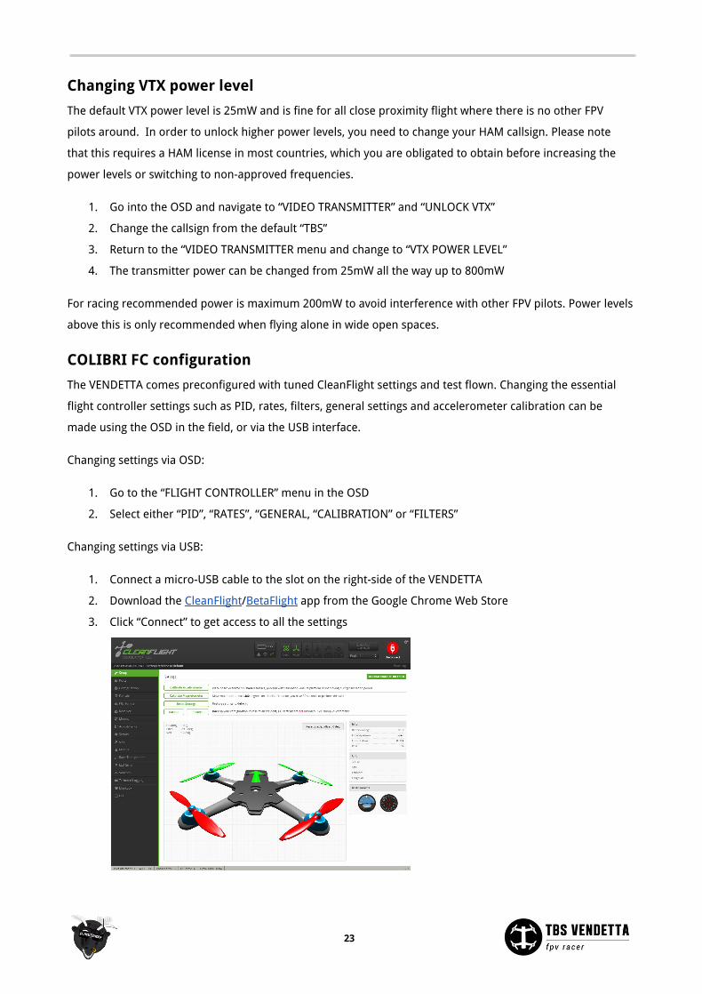
Changing settings via USB:
1. Connect a micro-USB cable to the slot on the right-side of the VENDETTA
2. Download the CleanFlight/BetaFlight app from the Google Chrome Web Store
3. Click “Connect” to get access to all the settings
23
OSD configuration
The VENDETTA OSD is built around the full-fledged TBS CORE PRO OSD and detailed description of all the
parameters is outlined in the official manual: http://www.team-blacksheep.com/tbs-core-pro-manual.pdf
The following is a concise summary specific for the VENDETTA.
On-Screen Display
● Units (GPS required) - Standard unit to use on the OSD
○ Speed - Metric (km/h), Imperial (mi/h), Knots (kts/h)
○ Distance - Metric (m), Imperial (ft)
○ Altitude - Metric (m), Imperial (ft)
● RSSI - Received Signal Strength Indicator signal from the receiver (if connected physically)
○ Source - Off/CrossFire/EzUHF OSD Link/Digital (PWM)/Analog (voltage) - RSSI signal source
type
○ Alarm - Enable/Disable - Display a textual warning and the RSSI read-out will blink when the
signal is critical
● Battery - Power system monitoring
○ Alarm - Enable/Disable - Show warning when battery voltage crosses critical level
○ Level Input - Auto/Manual - How to detect the number of battery cells/voltage
○ Warning Level - 0.0 to 99.9V - Set the threshold when a low voltage alarm should trigger
○ Curr. Correction - 50 to 250% - Calibrate your current sensor if it is a little off. e.g. your fly a
battery and the OSD shows you you used 1000mAh but your charger let you charge
1200mAh, so you can set this value to 120% and the reading will match on the next flight
○ Backup Voltage - Disable/Enable - Enables the backup battery, if connected, so the OSD/GPS
can run while the rest of the system is down, e.g. to recover a downed aircraft
● General - OSD specific settings
○ Show Position - No/Yes - Display the GPS coordinates on the bottom of the screen, update
rate 1Hz - useful while watching a DVR recording to recover a downed aircraft
○ Show Heading - No/Yes - Show heading arrow pointing towards “home” base
○ Show Sats - Hide on fix/Always - Number of GPS satellites available and locked
○ OSD Color - White/Black - Color of text and outline, i.e. white core and black outline/glow
○ Power Index - Off / mAh/Min / mWh/Km mWh/Mi / mAh/Km mAh/Mi - Running indicator of
power economy
○ Warn. Show Time - 0.5 to 60.0 Seconds - Duration of how long warnings stay on the screen,
default for racers target is 0.8s and 2.5s for every other target
○ Summary Style - TBS/PAO/Off - End of flight summary screen layout, TBS style with
judgement or without (PAO)
○ Audio Telemetry - Off/ImmersionRC - When you do not use TBS UNIFY, the TELM solder
bridge closed and ImmersionRC decoder is attached to the VRX
24
○ OSD Type - Vendetta/CORE PRO -
○ Factory Reset - Reset all CORE PRO settings to default
● Artificial Horizon - Uses the gyro and accelerometer to estimate level plane
○ Show Horizon - Off/Basic - Shows a line in the middle of the display to indicate level position
● Callsign - Personal HAM licence number
○ Show Callsign - Minutely/Always/Off - Display the HAM callsign and mm:ss timer on the
lower-left corner
○ Enter Callsign - 0 to 10 characters - Enter your callsign, defaults to “TBS”
Flight Controller
● PID - Detailed Proportional–Integral–Derivative controller values for Roll, Pitch and Yaw
● Rate - Stick sensitivity multiplier values
● Settings - Looptime and Idle Motors settings
● Calibration - RC/Radio Calibration wizard for setting up the receiver or this can also be done in
CleanFlight and the data read back to the CORE PRO. Run the accelerometer calibration on a leveled
surface
● Filters - Advanced setup of Gyro and PD Cut Frequency settings
Video Transmitter
● VTX Unlock - Brings you to Callsign settings to change the id from the default “TBS”
● Band - A/B/Race/E/Airwave/User - Video transmitter frequency band
● Channel - 1 to 8 - Channel number (frequency) within the selected band
● Power Level - 25/200/500/800mW - Transmitter output power level
● VTX LED Strip - Changes color depending on the channel used
25
Receiver setup
If you upgrade the COLIBRI firmware or reset settings, you will lose the connection between the COLIBRI and
receiver.
To setup the connection via CleanFlight or BetaFlight:
1. Open CleanFlight/BetaFlight and hit “Connect”
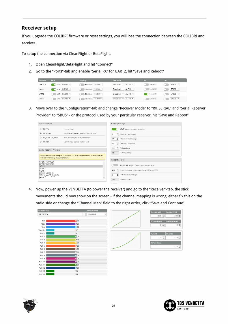
2. Go to the “Ports”-tab and enable “Serial RX” for UART2, hit “Save and Reboot”
3. Move over to the “Configuration”-tab and change “Receiver Mode” to “RX_SERIAL” and “Serial Receiver
Provider” to “SBUS” - or the protocol used by your particular receiver, hit “Save and Reboot”
4. Now, power up the VENDETTA (to power the receiver) and go to the “Receiver”-tab, the stick
movements should now show on the screen - if the channel mapping is wrong, either fix this on the
radio side or change the “Channel Map” field to the right order, click “Save and Continue”
26
Flight modes
With no flight mode switch, the default is ACRO-mode. If you are a beginner, it is recommended to add a two.
or three-position switch to toggle between ANGLE/HORIZON/ACRO-mode.
1. Open CleanFlight and go to the “Modes”-tab
2. Now, select an AUX-switch from the dropdown menu, these linked to the channel (listed in
“Receiver”)
3. For ACRO-mode, move the end-points between 900 and 1300, and for HORIZON-mode, move the
end-points between 1300 and 1700, click “Save”
Finally, try to power up the VENDETTA and radio, and toggle the flight mode-switch, the small marker
underneath the range should move and the label on the left will turn green when you change to ACRO or
HORIZON.
Lost alarm
In an event you should lose the quad in a large grassy field or obstructed area, a lost alarm beeper can come
in handy. By default the beeper is not set up. The easiest way to engage the beeper is to use a free
toggle-switch on the radio.
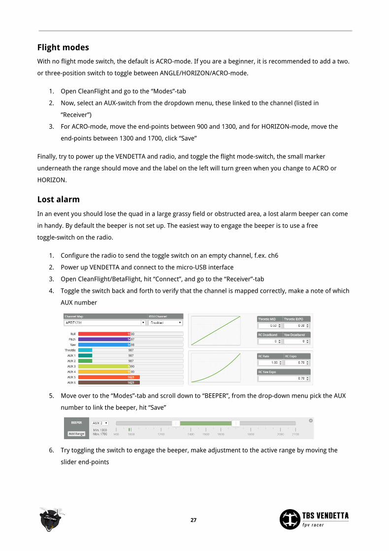
1. Configure the radio to send the toggle switch on an empty channel, f.ex. ch6
2. Power up VENDETTA and connect to the micro-USB interface
3. Open CleanFlight/BetaFlight, hit “Connect”, and go to the “Receiver”-tab
4. Toggle the switch back and forth to verify that the channel is mapped correctly, make a note of which
AUX number
5. Move over to the “Modes”-tab and scroll down to “BEEPER”, from the drop-down menu pick the AUX
number to link the beeper, hit “Save”
6. Try toggling the switch to engage the beeper, make adjustment to the active range by moving the
slider end-points
27
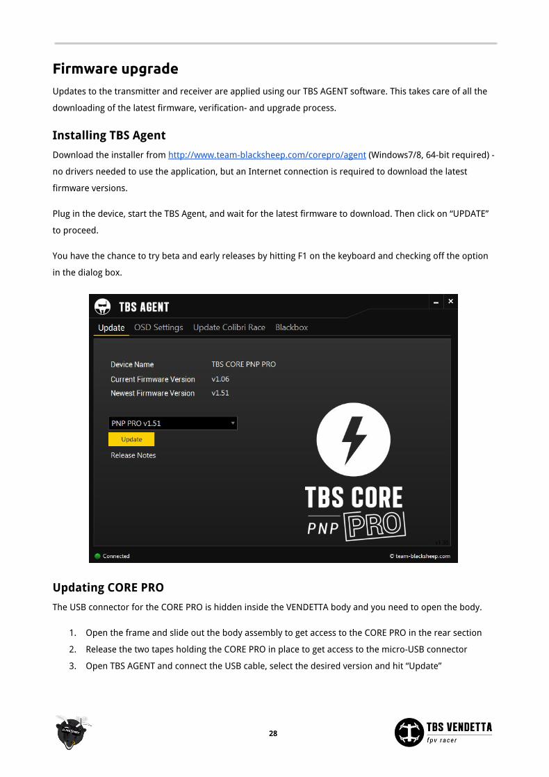
Firmware upgrade Updates to the transmitter and receiver are applied using our TBS AGENT software. This takes care of all the
downloading of the latest firmware, verification- and upgrade process.
Installing TBS Agent
Download the installer from http://www.team-blacksheep.com/corepro/agent (Windows7/8, 64-bit required) -
no drivers needed to use the application, but an Internet connection is required to download the latest
firmware versions.
Plug in the device, start the TBS Agent, and wait for the latest firmware to download. Then click on “UPDATE”
to proceed.
You have the chance to try beta and early releases by hitting F1 on the keyboard and checking off the option
in the dialog box.
Updating CORE PRO
The USB connector for the CORE PRO is hidden inside the VENDETTA body and you need to open the body.
1. Open the frame and slide out the body assembly to get access to the CORE PRO in the rear section
2. Release the two tapes holding the CORE PRO in place to get access to the micro-USB connector
3. Open TBS AGENT and connect the USB cable, select the desired version and hit “Update”
28
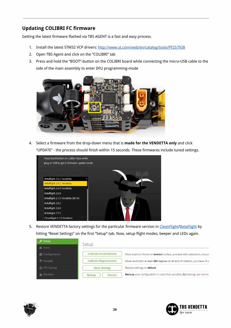
Updating COLIBRI FC firmware
Getting the latest firmware flashed via TBS AGENT is a fast and easy process.
1. Install the latest STM32 VCP drivers: http://www.st.com/web/en/catalog/tools/PF257938
2. Open TBS Agent and click on the “COLIBRI” tab
3. Press and hold the “BOOT”-button on the COLIBRI board while connecting the micro-USB cable to the
side of the main assembly to enter DFU programming-mode
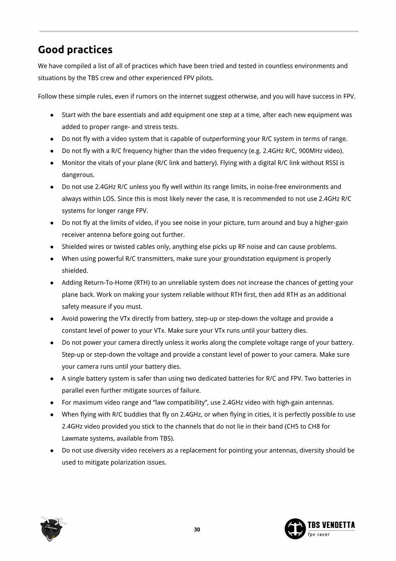
4. Select a firmware from the drop-down menu that is made for the VENDETTA only and click
“UPDATE” - the process should finish within 15 seconds. These firmwares include tuned settings.
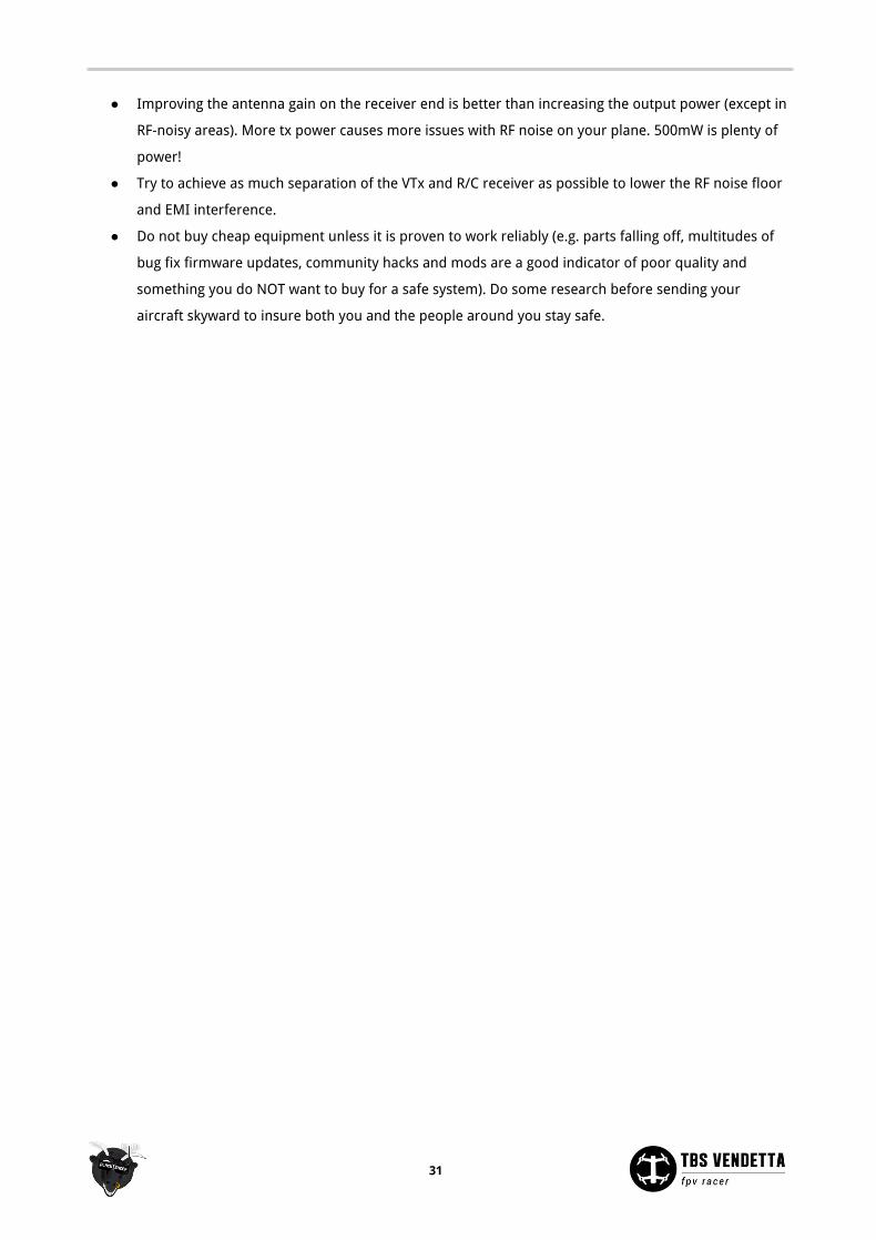
5. Restore VENDETTA factory settings for the particular firmware version in CleanFlight/BetaFlight by
hitting “Reset Settings” on the first “Setup”-tab. Now, setup flight modes, beeper and LEDs again.
29
Good practices We have compiled a list of all of practices which have been tried and tested in countless environments and
situations by the TBS crew and other experienced FPV pilots.
Follow these simple rules, even if rumors on the internet suggest otherwise, and you will have success in FPV.
● Start with the bare essentials and add equipment one step at a time, after each new equipment was
added to proper range- and stress tests.
● Do not fly with a video system that is capable of outperforming your R/C system in terms of range.
● Do not fly with a R/C frequency higher than the video frequency (e.g. 2.4GHz R/C, 900MHz video).
● Monitor the vitals of your plane (R/C link and battery). Flying with a digital R/C link without RSSI is
dangerous.
● Do not use 2.4GHz R/C unless you fly well within its range limits, in noise-free environments and
always within LOS. Since this is most likely never the case, it is recommended to not use 2.4GHz R/C
systems for longer range FPV.
● Do not fly at the limits of video, if you see noise in your picture, turn around and buy a higher-gain
receiver antenna before going out further.
● Shielded wires or twisted cables only, anything else picks up RF noise and can cause problems.
● When using powerful R/C transmitters, make sure your groundstation equipment is properly
shielded.
● Adding Return-To-Home (RTH) to an unreliable system does not increase the chances of getting your
plane back. Work on making your system reliable without RTH first, then add RTH as an additional
safety measure if you must.
● Avoid powering the VTx directly from battery, step-up or step-down the voltage and provide a
constant level of power to your VTx. Make sure your VTx runs until your battery dies.
● Do not power your camera directly unless it works along the complete voltage range of your battery.
Step-up or step-down the voltage and provide a constant level of power to your camera. Make sure
your camera runs until your battery dies.
● A single battery system is safer than using two dedicated batteries for R/C and FPV. Two batteries in
parallel even further mitigate sources of failure.
● For maximum video range and “law compatibility”, use 2.4GHz video with high-gain antennas.
● When flying with R/C buddies that fly on 2.4GHz, or when flying in cities, it is perfectly possible to use
2.4GHz video provided you stick to the channels that do not lie in their band (CH5 to CH8 for
Lawmate systems, available from TBS).
● Do not use diversity video receivers as a replacement for pointing your antennas, diversity should be
used to mitigate polarization issues.
30
● Improving the antenna gain on the receiver end is better than increasing the output power (except in
RF-noisy areas). More tx power causes more issues with RF noise on your plane. 500mW is plenty of
power!
● Try to achieve as much separation of the VTx and R/C receiver as possible to lower the RF noise floor
and EMI interference.
● Do not buy cheap equipment unless it is proven to work reliably (e.g. parts falling off, multitudes of
bug fix firmware updates, community hacks and mods are a good indicator of poor quality and
something you do NOT want to buy for a safe system). Do some research before sending your
aircraft skyward to insure both you and the people around you stay safe.
Manual written and designed by ivc.no in cooperation with TBS.
31