Embed Size (px)
Citation preview

Download from www.mindstien.com
www.basicknowledge.co.in
1
CHAPTER 1
INTRODUCTION TO
TATA TELESERVICES LTD
1.1 Introduction
1.2 Brief History of the company
1.3 Service offered by TTSL
1.3.1 Voice
1.3.2 Data
1.4 Partners of TTSL

Download from www.mindstien.com
www.basicknowledge.co.in
2
1.1 Introduction
Tata Teleservices Ltd (TTSL) offers its products and services to customers across
India under the name of "Tata Indicom".
TATA Teleservices limited is India's leading Private Basic Service Operator. TATA
Teleservices is an integral part of the TATA Group's holistic venture in the telecom
industry. The Group has a significant presence in all sectors of the telecom industry -
Basic, ISP, NLD and Broadband.
The company signed its license and inter-connects agreement with the Government of
India on November 4 1997, when the Government opened up the Basic Services business
to Private Operators.
TATA Teleservices brings the benefits of convergence to the customer's doorstep.
TTSL's wire line connections are a mix of both copper and fiber, which enable clear
voice transmission and faster data transmission. The Company is upgrading its wireless
network to 3G 1X with capabilities of handling speeds up to 144 kbps and has a full-
length managed network with centralized Network Management System. The network is
highly reliable and supports monitoring and maintenance.
TTSL's Pay Telephone Booths offer significant consumer benefits, including privacy &
comfort. Operators and customers also benefit through accurate billing. TTSL has clearly
demonstrated its leadership in Pay Telephony by setting up over 5000 Pay telephone
booths in Andhra Pradesh. The Company has successfully replicated these value added
services in the other five proposed circles of Delhi, Gujarat, Tamil Nadu, Karnataka &
Maharashtra, thus effectively servicing its customer base of 13,17,000 customers across
all the six circles it currently provides it services in.
1.2 Brief history of the Company
TATA Teleservices Limited is a customer-focused company, and aims to provide the
latest network supported by specialized IT systems, thereby ensuring an efficient and
cost-effective network and business operations. TTSL has entrusted Tata Consultancy
Services (TCS) with the task of complete IT provisioning, operation and maintenance.
Leading IT vendors like Keenan (for billing systems) and Oracle (for Enterprise Resource
Planning) are associated with TTSL for the provision of world class back office support.
TTSL's portfolio of products and services vary from basic features such as alarm service
and STD locking to value added services in call management such as call waiting, three-
way conference, call forwarding (immediate busy and no reply) and caller line
identification to advanced services such as Centrex, ISDN, leased lines and E1s. TTSL
was the first telecom service provider in the country to offer corporate telecom solutions
such as Centrex to its customers. TTSL also offers ISDN PRI to its customers and intends
to offer a wide range of telecommunication services.
TTSL is used the products of Lucent, Marconi, and Motorola.

Download from www.mindstien.com
www.basicknowledge.co.in
3
1.3 Services offered by TTSL
TTSL offered services in Voice as well as in Data as mentioned below.
1) Voice
TATA Indicom Mobile is based on the latest CDMA 3G-1X technology that offers
superior voice clarity and congestion-free networks. You can make and receive calls from
any landline, GSM cell phone or CDMA mobile phone from any other network in any
part country or the world.
Our handsets can of the work if you wish to switch your service provider to other CDMA
networks, but not with GSM networks. And indeed, GSM handsets will not work if the
service provider is on the CDMA platform. Calls can be made to or received from all
networks.
Current telecom regulation permits mobile phones based on Wireless in Local Loop
(WLL) technology (like TATA Indicom) to be provided within a specific geographic
limit termed as Short Distance Charging Area (SDCA), which usually corresponds to a
taluka or city like Mumbai, Delhi, Bangalore, Hyderabad, Chennai, Ahmedabad, etc. This
means that the handset will work only within the SDCA you are registered in (and hence
the phrase 'limited mobility'). Within the SDCA, calls including STD and ISD can be
made to or received from anywhere.
1.1 Landline phone connections
If you take a wire line connection, your telephone is connected to the TATA Indicom
exchange by a combination of high technology fiber - optic cables and copper cables. A
global standard today, fiber - optic cables enable our network to handle higher capacities
of load as compared to ordinary cables and at much higher transmission speeds. This
gives you trouble-free and faster connectivity.
1.2 Wireless Connections
When you take a wireless connection, your telephone is linked to the TATA Indicom
network via CDMA Wireless in Local Loop technology. In Wireless Local Loop (WLL)
technology, there are no cables connecting your telephone to the telephone exchange.
Instead, a Network Interface Unit (NIU) is installed within your premises and your phone
instrument is connected to it.
1.3 ISDN Lines

Download from www.mindstien.com
www.basicknowledge.co.in
4
ISDN, which stands for Integrated Services Digital Network, is a system of digital phone
connections that has been available for over a decade. This system allows data to be
transmitted simultaneously across the world using end-to-end digital connectivity. used to
analog connectivity so far) to your phone line for various applications such as data and
image transfer amongst others, in addition to normal voice telephone on the same line.
This system allows data to be transmitted simultaneously across the world using end-to-
end digital connectivity. With ISDN, two bearer channels carry voice and data.
1.4 Centrex
Centrex (Central Exchange) is a facility that enables a customer to utilize all the facilities
provided by an EPBX from TTSL’s wire line switch. It is a productivity booster that
helps the customer to utilize facilities similar to those offered by an EPBX while also
retaining the benefits of a direct line. With Centrex facility, one can access other
members of their group through 3 or 4 digit dialing. It is offered to corporate who have
multiple connections. It allows the caller to be directly routed to the received or the
extension without going through an exchange. It also serves as an intercom with
extension numbers for internal calls.
2) Data
2.1 E1 Links
This is an ideal solution for large business users who require a large number of telephone
lines to their EPABX. An E1 link is a 2 Mbps data circuit, which can carry 30 voice /
data channels. The benefits are:
1. Faster connectivity
2. Confidentiality
3. Guaranteed uptime levels
4. Optimal utilization of lines and resources
2.2 Basic/Primary Rate ISDN
2.2.1 Basic Rate ISDN
Basic Rate ISDN is what would typically be provided to the residential user. But that
does not mean to say a business would not use Basic Rate, it could be used in a small
office environment or as some form of backup for other services. In this overview we will
look at Basic Rate ISDN or BRI as it is sometimes called. In BRI there are 2 B channels
and 1D channel that operate at 128 Kbps. A maximum of 2 applications can run
simultaneously.
2.2.2 Primary Rate ISDN
Download from www.mindstien.com
www.basicknowledge.co.in
5
Primary rate ISDN is based on the same frame format as an E1 trunk using Common
Channel Signaling. Typically a business customer would have Primary Rate ISDN. In
PRI there are 30 B channels and 1D channel that operates at 2 Mbps. A maximum of 8
applications can run simultaneously.
2.3 Leased Line
There are three types of leased line used in modern digital communication system:
1. Managed Leased Line
2. Leased Line
3. Digital Leased Line
2.3.1 Managed Leased Line
These are point-to-point dedicated pipes starting from 64 Kbps to 2 Mbps lines. They can
also be used for Internet bandwidth access as point to ISP connectivity. Managed Leased
Line is connected to the Concentrator (Any Media). The fault in this type of Leased Line
can be detected through a terminal that is connected to the Concentrator. This terminal is
placed at the TTSL premises. This terminal has a ESM (Element Service Manager). ESM
has the details of all the Concentrator Sites, which monitors the equipment (LL). Through
ESM, it is detected which Any Media port has a problem. This type of Leased line is not
currently being offered by TTSL. Managed leased line is a costly affair. Managed Leased
Line services can be offered to the customers in n X 64 Kbps form varying from 64 Kbps
to 2 Mbps
2.3.2 Leased Line
This type of leased line does not give scope to detect the problem. An Engineer has to
check the end to end connectivity to identify the fault. A standard bandwidth of 2 Mbps is
offered to the customers. This facility is being offered by TTSL. The downtime is very
low and is a planned outage which means TTSL informs the customer about the period
when the Leased Line doesn't function.
2.3.2 Digital Leased Line (DLL)
In case of DLL, the bandwidth is offered in multiples of 64 Kbps. The bandwidth offered
is unlimited in this scenario. Digital Leased Line (DLL) offers a transmission media
between two points falling within the same or different CSA. The points A and B
respectively can be within a maximum distance of 3 kms from the CSA. The DLL
solution consists of one ISDN-NT1 and one Multicom ISDN router as customer premises
equipment (CPE) and customer does not require any modem or router at his premises.
The circuit so offered can present the Ethernet interface to the customer equipment.
The Ethernet interface from Multicom router is used to interface to Hub / Switch in
customer LAN.

Download from www.mindstien.com
www.basicknowledge.co.in
6
2.4 Virtual Private Network (VPN)
A Virtual Private Network (VPN) provides you the most cost-effective solution for
keeping your offices, staff and customers over multiple locations stay connected with
each other with maximum speed, convenience and security. VPNs allow a free flow of
information and quick data transfers and are highly secure because they are accessible
only through an authorized identified.
1.4 Partner of TTSL
To ensure superior transmission quality for our customers, we use the best technology
available.
To achieve this, TTSL has entered into partnership with various international leaders like:
1) Lucent, the world’s leading manufacturer of telecom Network equipment, to set up the
core network Infrastructure.
2) DMC, for microwave and Marconi for optical transmission network
3) TATA Consultancy Services, to help implement and integrate IT systems.
4) Kenan, USA for effective customer management.
5) Oracle Financials, for enterprise resource planning and small world, for Geographical
Information System (GIS).
Download from www.mindstien.com
www.basicknowledge.co.in
7
CHAPTER 2
INTRODUCTON
TO E1 LINE
2.1 Introduction
2.2 Why E1 is Demand?
2.3 How E1 Works. Making voice & data
Compatible
2.4 Alarms
2.1 Introduction
The aim of communication system has been to get more and more Information

Download from www.mindstien.com
www.basicknowledge.co.in
8
transmitted on a single cable. This involves gathering a number of sources together,
transmitting them together and then separating them and passing them to the individual
receivers.
E1 is a digital communication link that enables the transmission of voice, data, and video
signals at the rate of 2.048 Mbps. It was introduced in the 1960s.
2.2 Why is E1 in demand?
The current demand for E1 services can be linked to a number of tangible benefits.
1) Simplification
E1 simplifies the task of networking different types of communication equipment. To
illustrate, figure 1 show what your company’s communication network might be look like
without E1 and figure 2 Shows Company’s communication network with E1 link.
Figure 1 shows that telephone, fax, and computer applications would all require separates
lines. Typically, voice and low speed data serviced by analogue line, while high-speed
data application like computer are serviced by digital line. In figure 2 same things is
shown with E1 link installed.
E1 link carry both data and voice on a single digital communication link. In this way we
can reduce the task of managing many different networks.
2) Quality of services
E1 also provides a signal, which is superior in quality, then the analogue signal
provides. In analogue signal, noise and distortion is also amplified so it degrades the
quality of signal. While, in E1 system because of signal regeneration we got exact signal
at the receiver side.
Phone
System
Phone
System

Download from www.mindstien.com
www.basicknowledge.co.in
9
� �
� �
Figure 2.1
A communication network without E1
� �
E1 Link
� �
Figure 2.2
A communication network with E1
2.3 How E1 works – Making voice and data compatible
Many benefits of E1 are attributable to the fact that voice and data transmitted over a
single digital communication link. Since computer data consists of ones and zeros (the
symbol of the binary system), it is already compatible with E1’s digital format. However,
because voice signals are actually complex analogue waveform, they must be digitized to
achieve compatibility with E1.
FAX FAX
PC
PC
Phone
System
Phone
System
FAX FAX
PC
PC
M
U
X
M
U
X
Download from www.mindstien.com
www.basicknowledge.co.in
10
1) Pulse Code Modulation (PCM)
The most common method of Digitalized analog voice signals is a technique called PCM.
It is a sampling process that compresses a voice conversation into a 64 kbps standard rate
known as digital signal-level zero (DS0).
PCM is actually a two-step process. In the first step, the incoming analog signal is
sampled at 8,000 samples per second. The voice signal has a frequency of 300 Hz to 3400
KHz. And Shannon’s sampling theorem said that a sampled signal contains all the
information if the sampling frequency is at least twice of the highest frequency of the
analog signal to be sampled. Let the highest frequency of the voice signal is 4000Hz. So
Sampling rate = 2 * 4000
= 8000
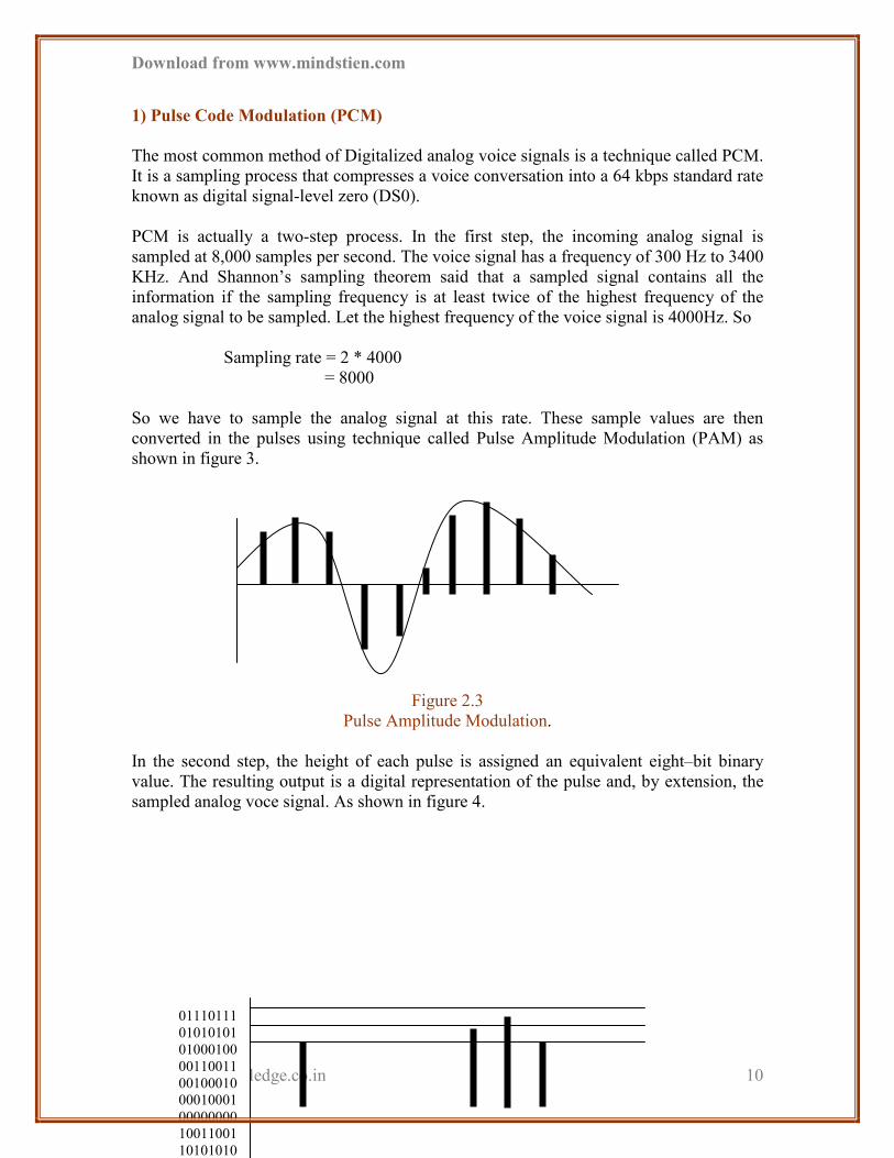
So we have to sample the analog signal at this rate. These sample values are then
converted in the pulses using technique called Pulse Amplitude Modulation (PAM) as
shown in figure 3.
Figure 2.3
Pulse Amplitude Modulation.
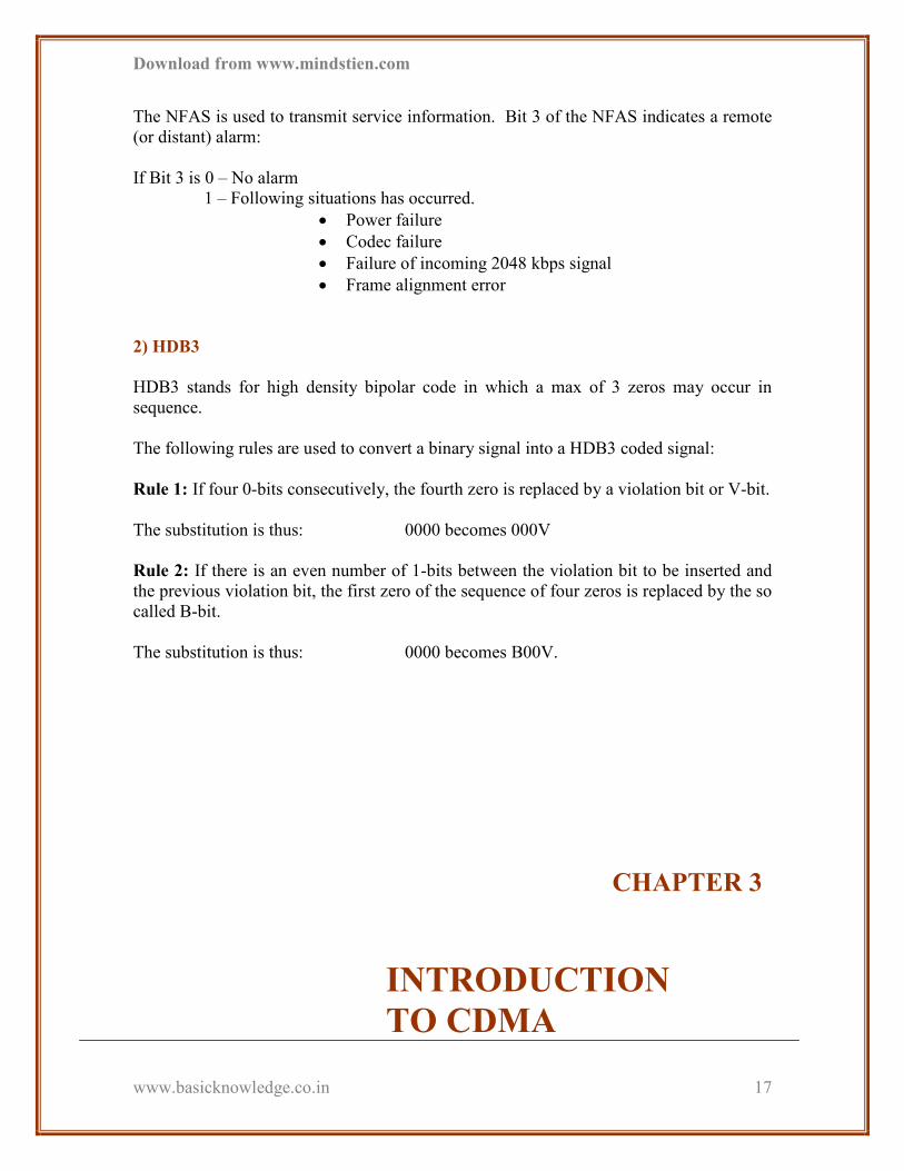
In the second step, the height of each pulse is assigned an equivalent eight–bit binary
value. The resulting output is a digital representation of the pulse and, by extension, the
sampled analog voce signal. As shown in figure 4.
01110111
01010101
01000100
00110011
00100010
00010001
00000000
10011001
10101010

Download from www.mindstien.com
www.basicknowledge.co.in
11
Figure 2.4
Quantization
Rate is obtained as explained below.
Rate = 8000 samples/second * 8 bit /sample
Rate = 64000 bits/second (single channel-DS0)
2) Time Division Multiplexing (TDM)
Once digitized, voice and data signals from many sources can be combined (i.e.
multiplexed) and transmitted over a single E1 link. This process is made possible by a
technique called TDM.
TDM divides the E1 link into 32 discrete 64 kbps timeslots. An identical number of DS0
signals is assigned to each time slots for transmission within the link as shown in figure.
� �
� �
Figure 2.5
Time Division Multiplexing (TDM)
3) 2.048 Mb/s Explained
In E1, the eight samples created in the PCM step (for voice traffic only) are grouped into
the 32 discrete DS0 timeslots created by TDM. Each group of 32 timeslots is called a E1
frame. Since each timeslot contains eight bits, the total number of information bits within
each frame totals 256 (32x8).
PCM
Data Data
PCM
TDM
TDM

Download from www.mindstien.com
www.basicknowledge.co.in
12
Since the DS0 signals are sampled 8,000 times per second, it means that 8,000 256 – bit
information frames are created during that period. So total BW comes,
BW = 8000 x 256
= 2048 kbps
= 2.048 Mbps
1 8
1 ………………………………………….. 31 32
Figure 2.6
E1 Frame = 256 bit
4) Signal Regeneration
Any newly created signal begins strongly, but degrades as it progresses along the E1 line.
Such attenuation is usually the results of line noise caused by interference from other
electrical sources. To compensate for these negative effects, devices called regenerative
repeaters sample and recreate the original signal at the periodic interval along the link as
shown in figure.
Figure 2.7
Regenerative Repeater
The number of regenerative repeaters that may be required along the path of E1 link
varies with the type of transmission media used.
5) Frame Type
Timeslots
TDM
Regenerative
Repeaters
Signal

Download from www.mindstien.com
www.basicknowledge.co.in
13
The primary frame consists of 32 timeslots numbered from 0 to 31. Two types of primary
frame are PCM30 and PCM31.
5.1 PCM30
In this type of frame 1 to 15 and 17 to 31 timeslots are used for traffic. While 0 slot is
used for synchronization and 16 is used for signaling purposes.
5.2 PCM31
In this type of frame slot 0 is used for synchronization while slot 1 to 31 is used for
traffic. As shown below
Figure 2.8
PCM 30 & PCM 31
6) Synchronization
The transmitter and receiver are synchronized to the PCM frame with the aid of Frame
Alignment Signal (FAS) which is transmitted in timeslot 0 of every second frame. The
Not Frame Alignment Signal (NFAS) is transmitted in timeslot 0 of the alternate
frames. Two types of frame are shown below which is transmitted along the 0 slot.
0 1 to 15 timeslots 16 17 to 31 timeslots
32 Timeslots
Synchronization slot Signalling slot
0 1 to 31 timeslots
32 Timeslots
Synchronization slot
0 1 to 31 Timeslots
X 0 0 1 1 0 1 1
8 bit

Download from www.mindstien.com
www.basicknowledge.co.in
14
Figure 2.9
Synchronization
6.1 FAS (Frame Alignment Signal)
Frame Alignment Signal (FAS) is transmitted at every even frame ( i.e. 2,4,6,8,… ).
Bit 1 is Si (C) where.
Si = reserved for international use.
C = CRC division remainder with PCM30 and PCM31
The receiving side of the PCM system determines the timeslot of the PCM frame on the
basis of the received frame alignment signals, so that received bits can be assigned to the
various channels in the correct sequence.
6.2 NFAS (Not Frame Alignment Signal)
The Not Frame Alignment Signal is used to carry information about the status of the link
and provide control signals for primary rate multiplexers.
Not Frame Alignment Signal (NFAS) is transmitted at every odd frame ( i.e.
1,3,5,7,9,…..)
Bit 1 is Si (M) where….
Si = reserved for international use.
M is used for transmitting the CRC - Multiframe alignment signal in
PCM30 or PCM31
Bit 2 is set to 1
Bit 3 (A-bit) shows remote alarm indication
FAS In even frames
NFAS In Odd frames
Download from www.mindstien.com
www.basicknowledge.co.in
15
Bit 4 to 8 are spare bits which are used in specific point-to-point applications within
national borders.
Bit Sa4 may be used for as a message-based data link for operations, maintenance and
performance monitoring.
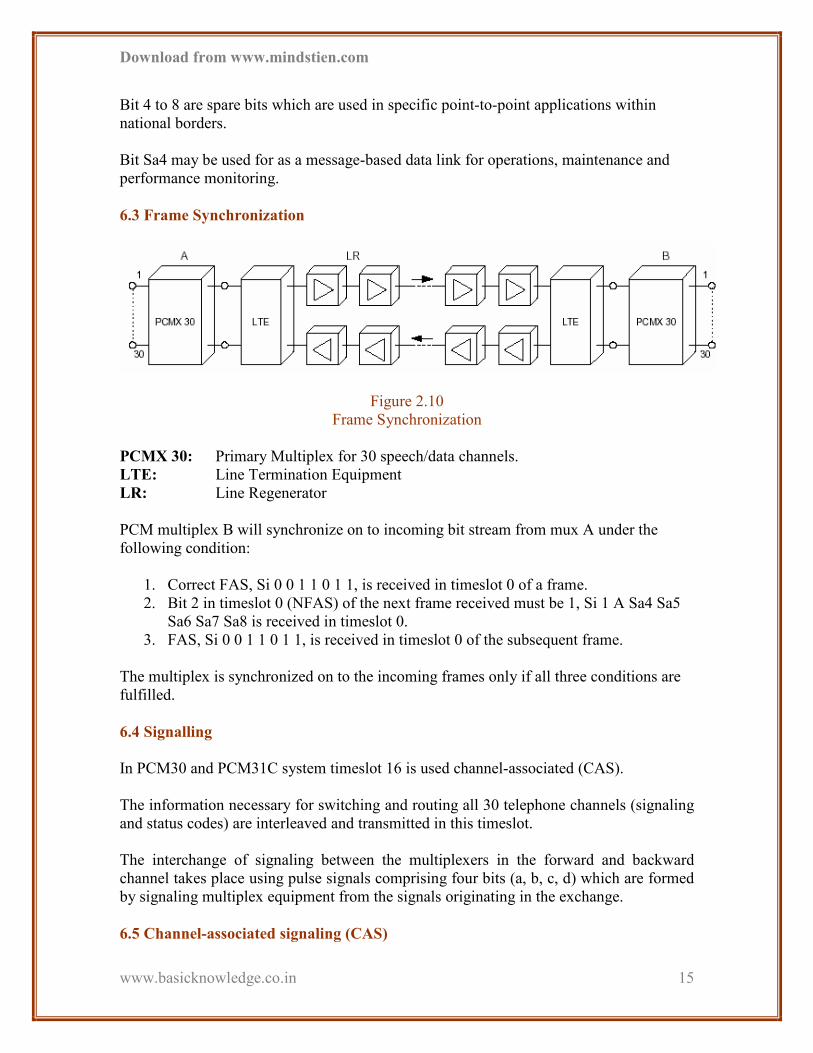
6.3 Frame Synchronization
Figure 2.10
Frame Synchronization
PCMX 30: Primary Multiplex for 30 speech/data channels.
LTE: Line Termination Equipment
LR: Line Regenerator
PCM multiplex B will synchronize on to incoming bit stream from mux A under the
following condition:
1. Correct FAS, Si 0 0 1 1 0 1 1, is received in timeslot 0 of a frame.
2. Bit 2 in timeslot 0 (NFAS) of the next frame received must be 1, Si 1 A Sa4 Sa5
Sa6 Sa7 Sa8 is received in timeslot 0.
3. FAS, Si 0 0 1 1 0 1 1, is received in timeslot 0 of the subsequent frame.
The multiplex is synchronized on to the incoming frames only if all three conditions are
fulfilled.
6.4 Signalling
In PCM30 and PCM31C system timeslot 16 is used channel-associated (CAS).
The information necessary for switching and routing all 30 telephone channels (signaling
and status codes) are interleaved and transmitted in this timeslot.
The interchange of signaling between the multiplexers in the forward and backward
channel takes place using pulse signals comprising four bits (a, b, c, d) which are formed
by signaling multiplex equipment from the signals originating in the exchange.
6.5 Channel-associated signaling (CAS)
Download from www.mindstien.com
www.basicknowledge.co.in
16
Interchange of signaling in the forward and backward directions is accomplished using
bits that only change state slowly. It is therefore sufficient to transmit these relatively
static signaling bits at a rate of 2 kbps for each subscriber.
As a result, the 64 kbps capacity of timeslot 16 is divided between the 30 subscriber
channels and 2 auxiliary channels for synchronization and alarms. A signaling multiframe
is formed which comprises 16 normal PCM frames.
Each signaling timeslot of the multiframe has a transmission capacity of 4 kbps (64 kbps
divided into 16.
6.6 Cyclic Redundancy Check (CRC)
With the introduction of ISDN (Integrated Services Digital Network), subscribers are
provided with transparent 64 kbps channels for speech or data transmission. Transparent
in this sense means that the binary signal transmitted by the subscriber is transmitted over
the entire signal path without being altered is in any way by analogue/digital conversion
or other means, with the bit sequence integrity preserved.
There is a danger with this type of data communication that the subscriber may
intentionally or unintentionally transmit the bit pattern 10011011 which corresponds to
the FAS. This may lead to the PCM multiplexer re-synchronizing to this apparent FAS,
with the result that all of the PCM channels will be incorrectly assigned.
2.4 Alarms
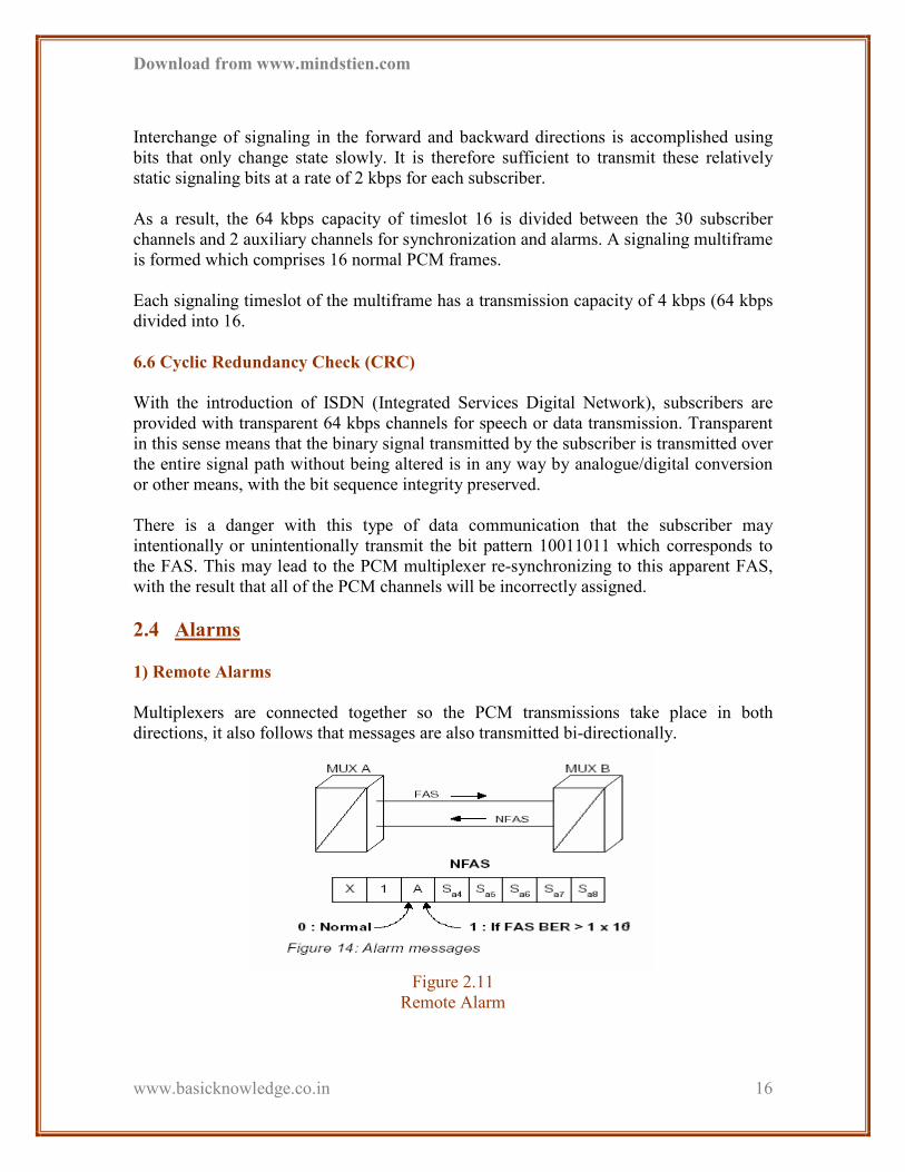
1) Remote Alarms
Multiplexers are connected together so the PCM transmissions take place in both
directions, it also follows that messages are also transmitted bi-directionally.
Figure 2.11
Remote Alarm
Download from www.mindstien.com
www.basicknowledge.co.in
17
The NFAS is used to transmit service information. Bit 3 of the NFAS indicates a remote
(or distant) alarm:
If Bit 3 is 0 – No alarm
1 – Following situations has occurred.
• Power failure
• Codec failure
• Failure of incoming 2048 kbps signal
• Frame alignment error
2) HDB3
HDB3 stands for high density bipolar code in which a max of 3 zeros may occur in
sequence.
The following rules are used to convert a binary signal into a HDB3 coded signal:
Rule 1: If four 0-bits consecutively, the fourth zero is replaced by a violation bit or V-bit.
The substitution is thus: 0000 becomes 000V
Rule 2: If there is an even number of 1-bits between the violation bit to be inserted and
the previous violation bit, the first zero of the sequence of four zeros is replaced by the so
called B-bit.
The substitution is thus: 0000 becomes B00V.
CHAPTER 3
INTRODUCTION
TO CDMA

Download from www.mindstien.com
www.basicknowledge.co.in
18
3.1 What is CDMA?
3.2 Overview of Multiple Access
Technology
3.3 Frequency Re-use
3.4 CDMA Spread Spectrum Technology
3.5 Generation of CDMA Signal
3.6 Code Channels used in CDMA
3.7 Call Processing Stages
3.8 CDMA Physical and Logical Channels
3.1 What is CDMA?
Code Division Multiple Access (CDMA) is a digital technology pioneered by
QUALCOMM that provides crystal clear voice quality in a new generation of wireless
communications products and services. Using digital encoding and "spread spectrum"
Radio Frequency (RF) techniques, CDMA provides better and more cost effective:
• Voice quality
• Privacy
• System capacity
• Flexibility
than other wireless technologies. CDMA also provides enhanced services such as:
• Short messaging
Download from www.mindstien.com
www.basicknowledge.co.in
19
• Internet access
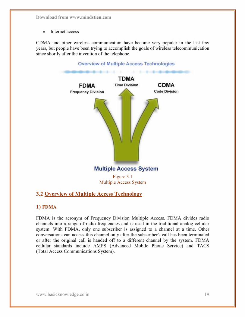
CDMA and other wireless communication have become very popular in the last few
years, but people have been trying to accomplish the goals of wireless telecommunication
since shortly after the invention of the telephone.
Figure 3.1
Multiple Access System
3.2 Overview of Multiple Access Technology
1) FDMA
FDMA is the acronym of Frequency Division Multiple Access. FDMA divides radio
channels into a range of radio frequencies and is used in the traditional analog cellular
system. With FDMA, only one subscriber is assigned to a channel at a time. Other
conversations can access this channel only after the subscriber's call has been terminated
or after the original call is handed off to a different channel by the system. FDMA
cellular standards include AMPS (Advanced Mobile Phone Service) and TACS
(Total Access Communications System).

Download from www.mindstien.com
www.basicknowledge.co.in
20
Figure 3.2
FDMA
2) TDMA
TDMA is a common multiple access technique employed in digital cellular systems. It
divides conventional radio channels into time slots to obtain higher capacity. Its standards
include North American Digital Cellular, Global System for Mobile Communications,
and PDC (Personal Digital Cellular). As with FDMA, no other conversations can access
an occupied TDMA channel until the channel is vacated.
Figure 3.3
TDMA
3) CDMA
CDMA uses a radically deferent approach. It assigns each subscriber a unique "code" to
put multiple users on the same wideband channel at the same time.
Both the mobile station and the base station to distinguish between conversations use the
codes, called “pseudo-random code sequences”.
Depending on the level of mobility of the system, it provides 10 to 20 times the capacity
of AMPS, and 4 to 7 times the capacity of TDMA.

Download from www.mindstien.com
www.basicknowledge.co.in
21
Figure 3.4
CDMA-A
Figure 3.5
CDMA-B
CDMA is the only one of the three technologies that can efficiently utilize spectrum
allocation and offer service to many subscribers without requiring extensive frequency
planning.
All CDMA users can share the same frequency channel because their conversations are
distinguished only by digital code, while TDMA operators have to coordinate the
allocation of channels in each cell in order to avoid interfering with adjacent channels.
The average transmitted power required by CDMA is much lower than what is required
by analog, FDMA and TDMA technologies.
3.3 Frequency Re-use

Download from www.mindstien.com
www.basicknowledge.co.in
22
Figure 3.6
Frequency Re-use
1) Introduction of CDMA
Designers and planners of the communication systems are often concerned with the
efficiency with which the systems utilize the signal energy and bandwidth. In most
communication systems these are the most important issues. In some cases, it is
necessary for the system to resist external interference, to operate at low spectral energy,
to provide multiple access capability without external control and secure channel not
accessible to the outsiders. Thus, it is sometimes unavoidable to sacrifice some of the
efficiency in order to enhance these features. Spread spectrum techniques allow
accomplishing such objectives.
Figure 3.7
CDMA-C
The theoretical aspects of using spread spectrum in a strong interference environment
have been known for over forty years. It is only recently that practical implementations
became feasible. In the beginning, the spread spectrum technology was developed and
used for military purposes and their implementations were too expensive for the
commercial applications. New technological advancements such as VLSI, and advanced
signal processing techniques made it possible to develop less expensive spread spectrum
equipment for civilian use. Applications of this technology include cellular, wireless data
transmission and satellite communications. All of the spread-spectrum systems have to
satisfy two criteria:

Download from www.mindstien.com
www.basicknowledge.co.in
23
• The bandwidth of the transmitted signal must be greater then the transmitted
Signal.
• Transmitted bandwidth must be determined by some function that is independent
of the message and is known to the receiver.
Bandwidth expansion in spread spectrum systems is achieved by using a function that is
independent of the message, thus it is more susceptible to white noise as opposed to other
communication techniques, such as FM and PCM. Spread spectrum techniques have
other applications that make it unique and useful.
• These applications include
1. Anti-jam capability-particularly for narrow-band jamming.
2. Interference rejection.
3. Multiple-access capability.
4. Multi-path protection.
5. Convert operations or low probability of intercept (LPI).
6. Secure communications.
7. Improved spectral efficiency-in special circumstances.
8. Ranging.
CDMA is a wireless communications technology that uses the principle of spread
spectrum communication. The intent of CDMA technology is to provide increased
bandwidth in a limited frequency system, but has also other advantages including
extended range and more secure communications. In a CDMA system, a narrowband
message signal is multiplied by a spreading signal, which is a pseudo-noise code
sequence that has a rate much greater than the data rate of the message. CDMA uses
these code sequences as a means of distinguishing between individual conversations. All
users in the CDMA system use the same carrier frequency and may transmit
simultaneously. In this document I will be discussing about CDMA in detail.
CDMA is a driving technology behind the rapidly advancing personal communications
industry. Because of its greater bandwidth, efficiency, and multiple access capabilities,
CDMA is becoming a leading technology for relieving the spectrum congestion caused
by the explosion in popularity of cellular mobile phones, fixed wireless telephones, and
wireless data terminals. Since becoming an officially recognized digital cellular protocol,
CDMA is being rapidly implemented in the wireless communications networks of many
large communications corporations.
CDMA stands for "Code Division Multiple Access." It is a form of spread-spectrum, an
advanced digital wireless transmission technique. Instead of using frequencies or time
slots, as do traditional technologies, it uses mathematical codes to transmit and
distinguish between multiple wireless conversations. Its bandwidth is much wider than
that required for simple point-to-point communications at the same data rate because it
uses noise-like carrier waves to spread the information contained in a signal of interest

Download from www.mindstien.com
www.basicknowledge.co.in
24
over a much greater bandwidth. However, because the conversations taking place are
distinguished by digital codes, many users can share the same bandwidth simultaneously.
The advanced methods used in commercial CDMA technology improve capacity,
coverage and voice quality, leading to a new generation of wireless networks.
Old-fashioned radio receivers separate stations and channels by filtering in the frequency
domain. CDMA receivers, conversely, separate communication channels by a pseudo-
random modulation that is applied and removed in the digital domain. Multiple users can
therefore occupy the same frequency band. This universal frequency reuse is crucial to
CDMA's distinguishing high spectral efficiency. CDMA has gained international
acceptance by cellular radio system operators as an upgrade because of its universal
frequency reuse and noise-like characteristics. CDMA systems provide operators and
subscribers with significant advantages over analog and conventional TDMA-based
systems.
The 850MHz CDMA band is most popularly used all over the world. This band as
mentioned in the previous slide works between
• 824-849MHz Used for the Reverse link communication
• 869-894MHz Used for the Forward link communication
The CDMA band is divided into sub bands as shown above. The Total Band of 25MHz is
divided into small channels of 30KHz each. An actual CDMA carrier will be using a
multiple of the 30KHz channels. That means for an actually utilized bandwidth of
1.23MHz we will need 41X30KHz channels.
The Following equation gives the relationship between the channel numbers and the
actual frequency.
Reverse Link Frequency = (825 + N0.03) MHz
Forward Link Frequency = (870 + N0.03) MHz
Where N = CDMA channel number
3.4 CDMA Spread Spectrum Technology
Download from www.mindstien.com
www.basicknowledge.co.in
25
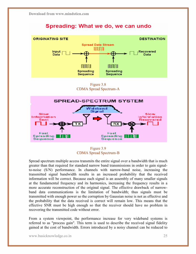
Figure 3.8
CDMA Spread Spectrum-A
Figure 3.9
CDMA Spread Spectrum-B
Spread spectrum multiple access transmits the entire signal over a bandwidth that is much
greater than that required for standard narrow band transmissions in order to gain signal-
to-noise (S/N) performance. In channels with narrow-band noise, increasing the
transmitted signal bandwidth results in an increased probability that the received
information will be correct. Because each signal is an assembly of many smaller signals
at the fundamental frequency and its harmonics, increasing the frequency results in a
more accurate reconstruction of the original signal. The effective drawback of narrow-
band data communications is the limitation of bandwidth; thus signals must be
transmitted with enough power so the corruption by Gaussian noise is not as effective and
the probability that the data received is correct will remain low. This means that the
effective SNR must be high enough so that the receiver should have no problem in
recovering the transmitted code without error.
From a system viewpoint, the performance increase for very wideband systems is
referred to as "process gain". This term is used to describe the received signal fidelity
gained at the cost of bandwidth. Errors introduced by a noisy channel can be reduced to

Download from www.mindstien.com
www.basicknowledge.co.in
26
any desired level without sacrificing the rate of information transfer using Claude
Shannon's equation describing channel capacity:
C=W log 2 (1+S/N )
Where,
C = Channel capacity in bits per second,
W = Bandwidth,
S/N = Energy per bit/Noise power.
The benefits of increasing bandwidth become clearer. The S/N ratio may be decreased
without decreasing the bit error rate. This means that the signal may be spread over a
large bandwidth with smaller spectral power levels and still achieve the required data
rate. If the total signal power is interpreted as the area under the spectral density curve,
then signals with equivalent total power may have either a large signal power
concentrated in a small bandwidth or a small signal power spread over a large bandwidth.
1) The main issues in a communication system
The three issues in a communication system are:
• Capacity
• Delay
• Error detection/correction.
Capacity concerns how much information you can deliver from the source to the
destination.
Delay issues are those involving delivery of information in the shortest time.
Error detection/correction is a method to reduce errors in the delivery of information.
Think about problems you may have experienced due to these issues. For example, there
may be a capacity problem in your carrier's system if you experience trouble placing a
call
2) How CDMA works?
The words “Code” and “Division” are important parts of how CDMA works. CDMA
uses codes to convert between analog voice signals and digital signals. CDMA also uses
codes to separate (or divide) voice and control data into data streams called “Channels”.
These digital data streams channels should not be confused with frequency channels.
3.5 Generation of CDMA Signal
Download from www.mindstien.com
www.basicknowledge.co.in
27
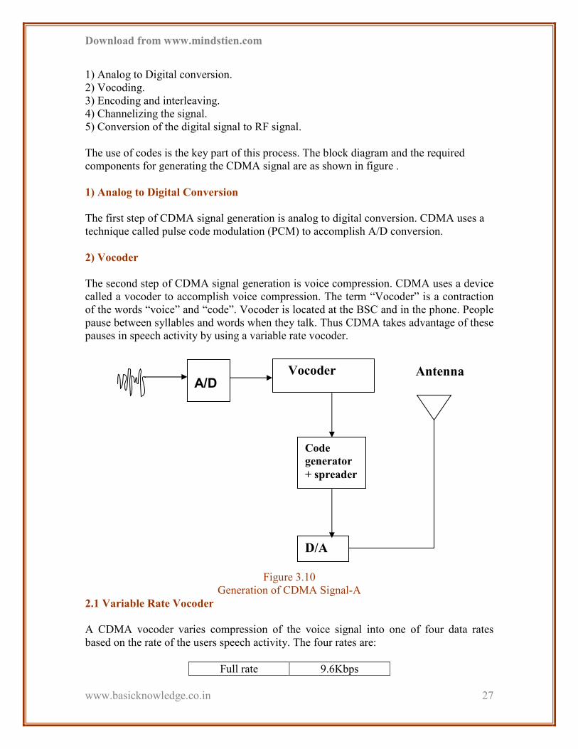
1) Analog to Digital conversion. 2) Vocoding. 3) Encoding and interleaving. 4) Channelizing the signal. 5) Conversion of the digital signal to RF signal.
The use of codes is the key part of this process. The block diagram and the required
components for generating the CDMA signal are as shown in figure .
1) Analog to Digital Conversion
The first step of CDMA signal generation is analog to digital conversion. CDMA uses a
technique called pulse code modulation (PCM) to accomplish A/D conversion.
2) Vocoder
The second step of CDMA signal generation is voice compression. CDMA uses a device
called a vocoder to accomplish voice compression. The term “Vocoder” is a contraction
of the words “voice” and “code”. Vocoder is located at the BSC and in the phone. People
pause between syllables and words when they talk. Thus CDMA takes advantage of these
pauses in speech activity by using a variable rate vocoder.
Figure 3.10
Generation of CDMA Signal-A
2.1 Variable Rate Vocoder
A CDMA vocoder varies compression of the voice signal into one of four data rates
based on the rate of the users speech activity. The four rates are:
Full rate 9.6Kbps
A/D
D/A
Code
generator
+ spreader
Vocoder Antenna

Download from www.mindstien.com
www.basicknowledge.co.in
28
1/2 rate 4.8Kbps
1/4 rate 2.4Kbps
1/8 rate 1.2Kbps
Table 3.1
Variable Rate Vocoder
The vocoder uses its full rate when a person is talking very fast. It uses the 1/8 rate when
the person is silent.
2.2 Vocoder Types
CDMA systems can use either an 8Kbps or 13kbps vocoder to maximize capacity. The
13Kbps vocoder was later developed to provide a more baud line quality voice signal.
The improvement in quality was worth the slight reduction in capacity.
Recently the CDMA community adopted a new 8kbps vocoder. This new vocoder is
usually referred as the EVRC (Extended Variable Rate Coding). It combines the quality
of 13Kbps vocoding with the capacity of the 8Kbps data rate.
Figure 3.11
Generation of CDMA Signal-B
3) Encoding and Interleaving
Encoders and interleaves are built into the BTS and the phones. The purpose of the encoding and interleaving is to build a redundancy into the signal so that information lost
in transmission can be recovered.
The type of encoding done at this stage is called “Convolution Encoding”. A simplified
encoding scheme is shown below:
Bit A B C D
Encoded Symbol A A A B B B C C C D D D
Error A A A B B ? ? ? C D D D
A/D VOCODER
PCM
1011011
Vocoded Signal
or Voice

Download from www.mindstien.com
www.basicknowledge.co.in
29
Decoded Bits A B ? D
Table 3.2
Bit Encoding
A digital message consists of four bits (A, B, C, D) of vocoded data. Each bit is repeated
three times. These encoded bits are called symbol.
The decoder at the receiver uses a majority logic rules.
3.1 Interleaving
Interleaving is a simple but powerful method of reducing the effect of burst errors and
recovering lost bits. In this example shown here the symbols from each group are
interleaved in a pattern that the receivers know.
Bit A B C D
Symbol A A A B B B C C C D D D
Interleaved Symbol ABC DAB CDA BCD
Errors ABC D?? ??A BCD
Deinterleaved A?A B?B C?C D?D
Decoded bits A B C D
Table 3.3
Bit Interleaving
4) Channelizing the signal
The encoded voice data is further encoded to separate it from other encoded voice data.
The encoded symbols are then spread over the entire bandwidth of the CDMA channel.
This process is called Channelization.
CDMA uses two types of Codes:
1. Walsh Codes
This type of coding is used in forward link. Walsh codes provide a means to uniquely
identify each user on the forward link. Walsh codes have a unique mathematical property
– “they are orthogonal”. In other words ,Walsh codes are unique enough that the voice
data can only be recovered by a receiver applying the same Walsh code. All other signals
are discarded as background noise.
Download from www.mindstien.com
www.basicknowledge.co.in
30
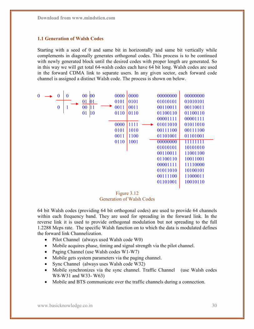
1.1 Generation of Walsh Codes
Starting with a seed of 0 and same bit in horizontally and same bit vertically while
complements in diagonally generates orthogonal codes. This process is to be continued
with newly generated block until the desired codes with proper length are generated. So
in this way we will get total 64-walsh codes each have 64 bit long. Walsh codes are used
in the forward CDMA link to separate users. In any given sector, each forward code
channel is assigned a distinct Walsh code. The process is shown on below.
0 0 0 00 00 0000 0000 00000000 00000000
01 01 0101 0101 01010101 01010101
0 1 00 11 0011 0011 00110011 00110011
01 10 0110 0110 01100110 01100110
00001111 00001111
0000 1111 01011010 01011010
0101 1010 00111100 00111100
0011 1100 01101001 01101001
0110 1001 00000000 11111111
01010101 10101010
00110011 11001100
01100110 10011001
00001111 11110000
01011010 10100101
00111100 11000011
01101001 10010110
Figure 3.12
Generation of Walsh Codes
64 bit Walsh codes (providing 64 bit orthogonal codes) are used to provide 64 channels
within each frequency band. They are used for spreading in the forward link. In the
reverse link it is used to provide orthogonal modulation but not spreading to the full
1.2288 Mcps rate. The specific Walsh function on to which the data is modulated defines
the forward link Channelization.
• Pilot Channel (always used Walsh code W0)
• Mobile acquires phase, timing and signal strength via the pilot channel.
• Paging Channel (use Walsh codes W1-W7)
• Mobile gets system parameters via the paging channel.
• Sync Channel (always uses Walsh code W32)
• Mobile synchronizes via the sync channel. Traffic Channel (use Walsh codes
W8-W31 and W33- W63)
• Mobile and BTS communicate over the traffic channels during a connection.

Download from www.mindstien.com
www.basicknowledge.co.in
31
Walsh sequences are also referred to as Wash Functions. These codes are generated at
1.2288 Mbps (Mcps) with a period of approximately 52 µs as illustrates below. These are
used to identify users on the forward link. For this reason they are also referred to as
either Walsh Channels or TCH. All base stations and mobile users have knowledge of all
Walsh codes.
Walsh Code generator Rate = 1.2288 Mcps
Time duration for the one Chip = 1/1.2288 Mcps
= 0.813 micro second
Total 64 chips are in one Walsh code so time between two Walsh code generations
= 0.813* 10-6 * 64
= 52.08 * 10-6 Second.
2. Pseudorandom Noise (PN)
This type of coding is used in reverse link. PN codes uniquely identify users on the
reverse link. A PN code is one that appears to be random. The PN codes used in CDMA
yield about 4.4 trillion combination of code. This is a key reason why CDMA is so
secure.
5) Conversion of Digital signal to RF signal
The BTS combines channelized data from all calls into one signal. It then converts the
digital signal to a RF signal for transmission.
3.6 Code Channels used in CDMA
A code channel is a stream of data designated for a specific user or person. This channel
may be voice or data or overhead control data. There are two basic links from BTS to
mobile unit and from mobile to BTS i.e. forward link and reverse link respectively. These
links use different types of channels.
CDMA
1 Chip of 813 ns
Download from www.mindstien.com
www.basicknowledge.co.in
32
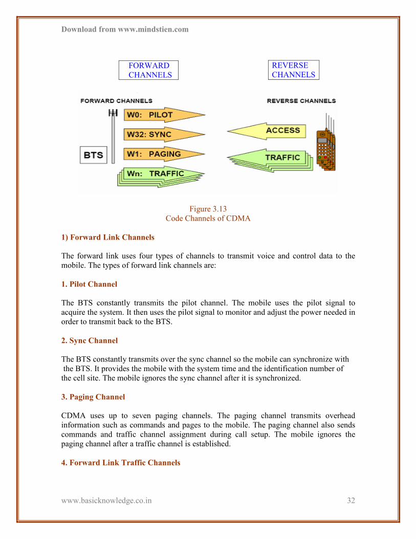
Figure 3.13
Code Channels of CDMA
1) Forward Link Channels
The forward link uses four types of channels to transmit voice and control data to the
mobile. The types of forward link channels are:
1. Pilot Channel
The BTS constantly transmits the pilot channel. The mobile uses the pilot signal to
acquire the system. It then uses the pilot signal to monitor and adjust the power needed in
order to transmit back to the BTS.
2. Sync Channel
The BTS constantly transmits over the sync channel so the mobile can synchronize with
the BTS. It provides the mobile with the system time and the identification number of
the cell site. The mobile ignores the sync channel after it is synchronized.
3. Paging Channel
CDMA uses up to seven paging channels. The paging channel transmits overhead
information such as commands and pages to the mobile. The paging channel also sends
commands and traffic channel assignment during call setup. The mobile ignores the
paging channel after a traffic channel is established.
4. Forward Link Traffic Channels
REVERSE
CHANNELS FORWARD
CHANNELS
Download from www.mindstien.com
www.basicknowledge.co.in
33
CDMA uses between 55 and 61 forward traffic channels to send both voice and overhead
control data during a call. Once the call is completed, the mobile tunes back in to the
paging channel for commands and pages.
2) Reverse Link Channels
The reverse link uses two types of channels to transmit voice and control data to the BTS.
The types of reverse link channels are:
1. Access Channel
The mobile uses the access channel when not assigned to a traffic channel. The mobile
uses the access channel to:
• Originate the calls
• Respond to pages and commands from the base station
• Transmit overhead messages to the base station.
2. Reverse Link Traffic Channel
The reverse traffic channel is only used when there is a call. The reverse traffic channel
transmits voice data to the BTS. It also transmits the overhead control information during
the call.
3.7 Call Processing Stages
There are four stages or modes in CDMA call processing:
1) Initialization Mode
During initialization, the mobile:
- Acquires the system via the Pilot Code Channel
- Synchronizes with the system via the Sync Code Channel.
2) Idle Mode
The mobile is not involved in a call during idle mode, but it must stay in communication
with the base station
- The mobile and the base station communicate over the access and paging
code channels.
- The mobile obtains overhead information via the paging code channel.
3) Access Mode

Download from www.mindstien.com
www.basicknowledge.co.in
34
The mobile accesses the network via the Access code channel during call origination. The
Access channel and Paging channel carry the required call setup communication between
the mobile phone and the BTS until a traffic channel is established.
4) Traffic Mode
• During a Land To Mobile (LTM) call:
a. The mobile receives a page on the paging channel
b. The mobile responds on the access channel.
c. The traffic channel is established and maintained throughout the call.
• During a Mobile To Land (MTL) call:
d. The call is placed using the Access channel.
e. The base station responds on the paging channel.
f. The traffic channel is established.
3.8 CDMA Physical and Logical Channels
1) Physical Channel
Physical channels are described in terms of a wideband RF channel and code sequence.
As defined in IS-95, each RF channel is 1.2288 MHz wide. For each RF channel, there
are 64 Walsh sequences (W0 through W63) available for use on the forward link. These
Walsh sequences are commonly referred to as CDMA code channels.
2) Logical Channel
The physical channel that carry specific types of information are known as logical
channels. Logical channels in CDMA are divided into two categories: Traffic Channels
and Control Channels. For the forward link there are three types of Control/Signaling
channels and one Traffic Channel (per user). For the Reverse Link there is one type
Signaling Channel and one Traffic Channel per user.
It is important to note that signals on the forward link are identified by Walsh codes;
however, signals on the reverse link are identified by Long Codes.
1. Orthogonal Codes
Orthogonal codes have a zero correlation. Walsh code has a property of orthogonality.
Two orthogonal codes will never interfere with each other. CDMA system there are 64
unique Walsh codes, each have 64 bits long. When we X-OR two codes and we get equal
numbers of 0 and 1 then these two codes are orthogonal to each other and have a zero
correlation.
Orthogonality = Equal Number of Matches and Mismatches

Download from www.mindstien.com
www.basicknowledge.co.in
35
2. Pseudo random Noise (PN) code
PN code has randomness properties. If the current state and the generating function of the
PN code are known, the Future state of the code can be predicted. In CDMA One system
each base stations and all mobile in that base station use same set of three PN sequence
(two short codes and one long code).
The summary of all codes is given below:
Generation Rate: 1.2288Mcps
Length: 64 bits
Total No. of Code: 64
Repetition Rate: 64/1.2288Mcps = 52.08 micro second
Forward Link: Spreading the logical channel
Reverse Link: Orthogonal Modulation
Generation Rate: 1.2288Mcps
Length: 242 = 4398046511104 bits
Repetition Rate: 41 days
Forward Link: Scrambling of Paging and Traffic channel, Encryption
Reverse Link: Spreading, Encryption
Generation Rate: 1.2288Mcps
Length: 215 = 32768bits
Repetition Rate: 26.67 ms
Forward Link: Scrambling (Cell Identification), Synchronization
Reverse Link: Scrambling (Cell identification), Synchronization
CHAPTER 4
FUNCTION OF THE
Walsh
Code
Long
Code
Short
Code

Download from www.mindstien.com
www.basicknowledge.co.in
36
CELL - SITE
4.1 Function of the Cell-Site
4.2 Converting Digital Signal to RF Signal
4.3 Architecture of CDMA
4.4 Types of Call
4.5 Features of CDMA
4.6 Hand-Offs in CDMA
4.7 Advantages of CDMA
4.8 Site Structure
• How does the cellular system work?
Cellular service providers used a network of cells in a geographic area. This reduced the
power requirements of the transceivers and accommodated more users. The main
components of an analog cellular network are:
• Public Switched Telephone Network
• Mobile Telephone Switching Office (MTSO)
• Cell site (also called "Base Station" or "BTS")
Everything from your telephone to the PSTN is considered part of the standard wire line
service.
Download from www.mindstien.com
www.basicknowledge.co.in
37
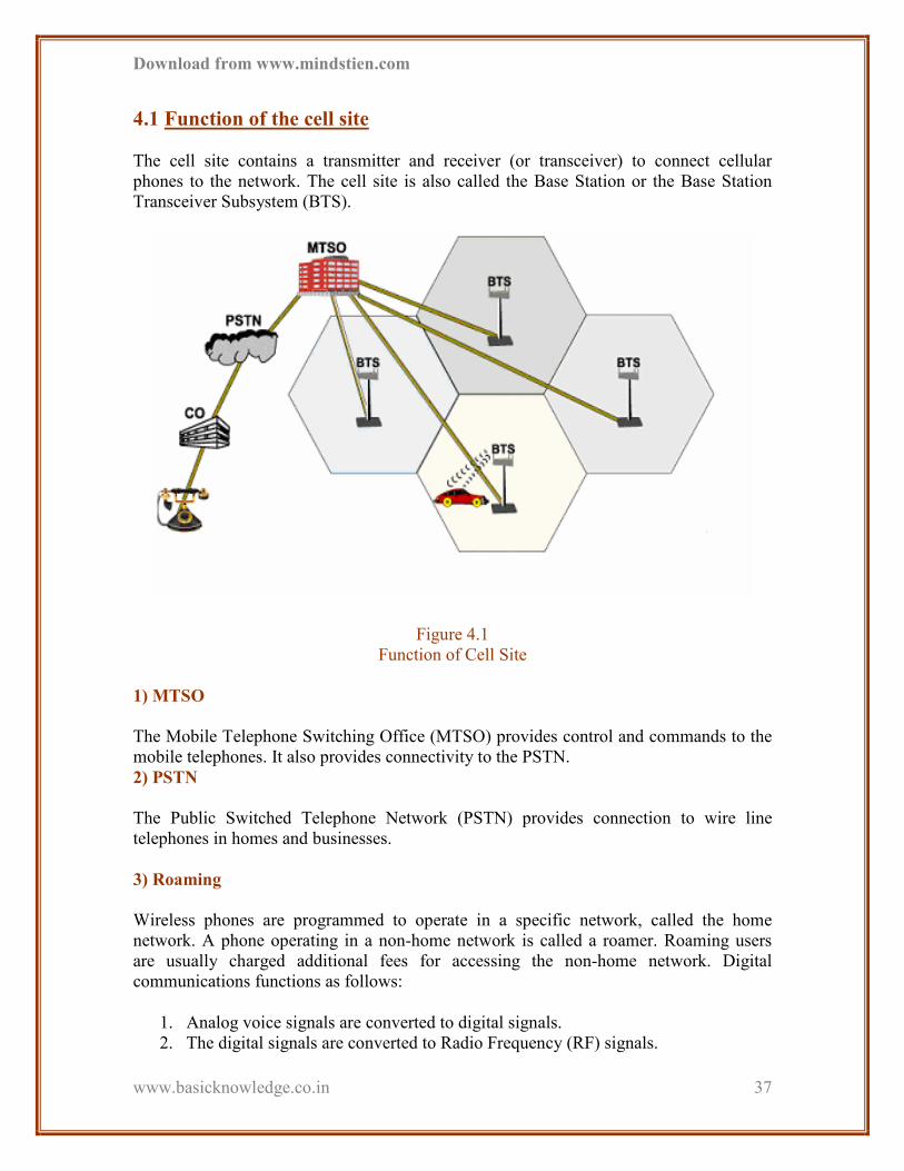
4.1 Function of the cell site
The cell site contains a transmitter and receiver (or transceiver) to connect cellular
phones to the network. The cell site is also called the Base Station or the Base Station
Transceiver Subsystem (BTS).
Figure 4.1
Function of Cell Site
1) MTSO
The Mobile Telephone Switching Office (MTSO) provides control and commands to the
mobile telephones. It also provides connectivity to the PSTN.
2) PSTN
The Public Switched Telephone Network (PSTN) provides connection to wire line
telephones in homes and businesses.
3) Roaming
Wireless phones are programmed to operate in a specific network, called the home
network. A phone operating in a non-home network is called a roamer. Roaming users
are usually charged additional fees for accessing the non-home network. Digital
communications functions as follows:
1. Analog voice signals are converted to digital signals.
2. The digital signals are converted to Radio Frequency (RF) signals.

Download from www.mindstien.com
www.basicknowledge.co.in
38
3. The RF signals are transmitted over the air.
4. The RF signals are received then converted to digital signals.
The digital signals are used to reconstruct the analog voice signals.
Figure 4.2
Digital Communication
4) Human Speech
Voice is an analog signal. A person involved in a two-way conversation usually only
transmits 40% of the time. The other 60% of the time includes pauses and listening to the
other person. Digital telecommunications exploits these and other properties of the
human voice.
4.2 Converting digital signals to RF signals
Digital information must be converted to a Radio Frequency (RF) signal in order to be
transmitted over the air. An RF signal may carry the information on the phase, frequency
and/or amplitude of the wave.
1) Digital wireless systems
Key elements of digital wireless systems include:
• Network components and equipment
• The interrelationship between the components
2) Network Components

Download from www.mindstien.com
www.basicknowledge.co.in
39
A digital wireless system has two basic components:
• Mobile phones
• Infrastructure equipment
Figure 4.3
Converting Digital Signal to RF Signal
3) Infrastructure equipment
The equipment that provides the interconnection between the phones and PSTN is called
"infrastructure." A CDMA system requires two pieces of infrastructure equipment. The
first is the "Base Station Transceiver Subsystem" (BTS). The other is the "Base Station
Controller" (BSC).
4) Base Station Transceiver Subsystem
The Base Station Transceiver Subsystem is most commonly just called the "BTS."
However, you will sometimes hear it referred to more simply as the Base Station (BS).
Sometimes it's called the "cell site," but don't confuse it with an analog cellular cell site.
The two function very differently. The BTS comes in both an indoor and an outdoor
model. The outdoor BTS is sometimes called an "OBTS."
4.3 Architecture of CDMA
Download from www.mindstien.com
www.basicknowledge.co.in
40
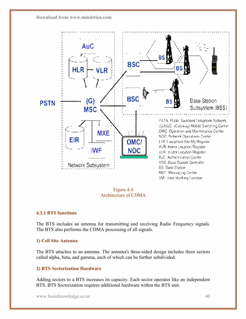
Figure 4.4
Architecture of CDMA
4.3.1 BTS functions
The BTS includes an antenna for transmitting and receiving Radio Frequency signals.
The BTS also performs the CDMA processing of all signals.
1) Cell Site Antenna
The BTS attaches to an antenna. The antenna's three-sided design includes three sectors
called alpha, beta, and gamma, each of which can be further subdivided.
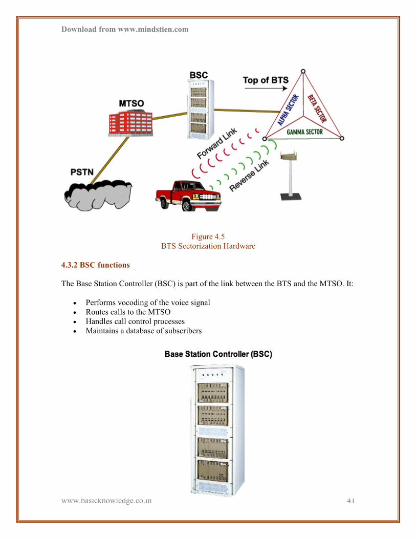
2) BTS Sectorization Hardware
Adding sectors to a BTS increases its capacity. Each sector operates like an independent
BTS. BTS Sectorization requires additional hardware within the BTS unit.
Download from www.mindstien.com
www.basicknowledge.co.in
41
Figure 4.5
BTS Sectorization Hardware
4.3.2 BSC functions
The Base Station Controller (BSC) is part of the link between the BTS and the MTSO. It:
• Performs vocoding of the voice signal
• Routes calls to the MTSO
• Handles call control processes
• Maintains a database of subscribers

Download from www.mindstien.com
www.basicknowledge.co.in
42
Figure 4.6
Base Station Controller (BSC)
1) Network Interconnects
There are three types of interconnects in a CDMA network:
• Mobile to BTS. These include both forward and reverse radio links
• BTS to BSC. This is called the backhaul. This connection is usually via T1 or E1
lines.
• BSC to MTSO. This connection uses standard wire line methods.
4.3.3 MSC functions
The primary node in a CDMA network is the MSC. It is the node which controls calls
both to MSs and from MSs. The primary functions of an MSC include the following:
1) Switching and Call Routing
An MSC controls call set-up, supervision and release and may interact with other nodes
to successfully establish a call. This includes routing of calls from MSs to other networks
such as a PSTN.
2) Charging
An MSC contains functions for charging mobile calls and information about the
particular charge rates to apply to a call at any given time or for a given destination.
During a call it records this information and stores it after the call, e.g. for output to a
billing centre.
3) Service provisioning
Supplementary services are provided and managed by an MSC. In addition, the SMS
service is handled by MSCs.
4) Communication with HLR
The primary occasion on which an MSC and HLR communicate is during the set-up of a
call to an MS, when the HLR requests some routing information from the MSC.
5) Communication with the VLR
Associated with each MSC is a VLR, with which it communicates for subscription
information, especially during call set-up and release.

Download from www.mindstien.com
www.basicknowledge.co.in
43
6) Communication with other MSCs
It may be necessary for two MSCs to communicate with each other during call set-up or
handovers between cells belonging to different MSCs.
7) Control of connected BSCs
As the BSS acts as the interface between the MSs and the SS, the MSC has the function
of controlling the primary BSS node: the BSC. Each MSC may control many BSCs,
depending on the volume of traffic in a particular MSC service area. An MSC may
communicate with its BSCs during; for example, call set-up and handovers between two
BSCs.
4.3.4 Gateway MSC (GMSC)
Gateway functionality enables an MSC to interrogate a HLR in order to route a mobile
terminating call. It is not used in calls from MSs to any terminal other than another MS.
For example, if a person connected to the PSTN wants to make a all to a CDMA mobile
subscriber, then the PSTN exchange will access the CDMA network by first connecting
the call to a GMSC. The GMSC requests call routing information from the HLR which
provides information about which MSC/VLR to route the call to. The same is true of a
call from an MS to another MS.
4.3.5 HLR functions
Each operator has a database with information about all subscribers belonging to that
specific service provider. It is used for the following purposes:
1. Registering subscriber’s MDN and IMSI numbers.
2. Storing subscriber’s categories and services.
3. Keeping track of which MSC/VLR is serving the subscriber.
4. Ordering a serving MSC/VLR to delete its record about a Subscriber.
4.3.6 VLR Functions
The VLR is implemented in the same switch as the MSC, which is then referred to as an
MSC/VLR.
It contains temporary information about the mobile subscriber visiting this specific
MSC/VLR Service Area.
It also performs location updating of the HLR.
The VLR contains a copy of the subscriber information from the HLR where it is
registered, means subscriber’s home location.

Download from www.mindstien.com
www.basicknowledge.co.in
44
Since VLR has a set of information about the mobile subscriber in its Service Area, the
HLR does not need to be consulted about subscriber data very often. This considerably
reduces the signaling to HLR.
Figure 4.7
VLR-HLR Interface
4.3.7 Authentication Centre (AUC)
PLMNs need a higher level of protection than traditional telecommunication networks.
Therefore, to protect CDMA systems, the following security functions have been defined:
1) Subscriber Authentication
By performing authentication, the network ensures that no unauthorized users can access
the network, including those which are attempting to impersonate others.
2) Radio Information Ciphering
The information sent between the network and an MS is ciphered. An MS can only
decipher information intended for it self.
3) Mobile Equipment Identification
Because the subscriber and equipment are separate in CDMA, it is necessary to have a
separate authentication process for the MS equipment. This ensures, e.g. that a mobile
terminal which has been stolen is not able to access the network.
4) Subscriber Identity Confidentiality
During communication with an MS over a radio link, it is desirable that the real identity
(IMSI) of the MS is not always transmitted. Instead a temporary identity (TLDN) can be
used. This helps to avoid subscription fraud.
Download from www.mindstien.com
www.basicknowledge.co.in
45
4.3.8 Equipment Identity Register (EIR)
In CDMA there is a distinction between subscription and mobile equipment. As
mentioned above, the AUC checks the subscription at access. The EIR checks the mobile
equipment to prevent a stolen or non-type-approved MS from being used.
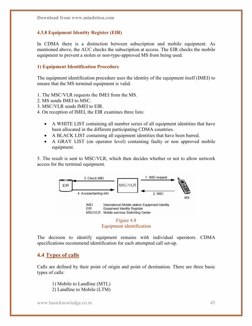
1) Equipment Identification Procedure
The equipment identification procedure uses the identity of the equipment itself (IMEI) to
ensure that the MS terminal equipment is valid.
1. The MSC/VLR requests the IMEI from the MS.
2. MS sends IMEI to MSC.
3. MSC/VLR sends IMEI to EIR.
4. On reception of IMEI, the EIR examines three lists:
• A WHITE LIST containing all number series of all equipment identities that have
been allocated in the different participating CDMA countries.
• A BLACK LIST containing all equipment identities that have been barred.
• A GRAY LIST (on operator level) containing faulty or non approved mobile
equipment.
5. The result is sent to MSC/VLR, which then decides whether or not to allow network
access for the terminal equipment.
Figure 4.8
Equipment identification
The decision to identify equipment remains with individual operators. CDMA
specifications recommend identification for each attempted call set-up.
4.4 Types of calls
Calls are defined by their point of origin and point of destination. There are three basic
types of calls:
1) Mobile to Landline (MTL)
2) Landline to Mobile (LTM)

Download from www.mindstien.com
www.basicknowledge.co.in
46
3) Mobile to Mobile (MTM)
Figure 4.9
Types of Calls
1) Mobile to Landline calls (MTL)
This call path proceeds from the mobile phone to BTS to respective BSC to the main
MTSO. From there it is diverted towards the PSTN, then to the CO, as shown in the
figure.
Figure 4.10
Mobile to Landline Calls (MTL)

Download from www.mindstien.com
www.basicknowledge.co.in
47
2) Landline to Mobile calls (LTM)
This call path proceeds follows from the Land line phone to its CO to the PSTN . from
there it is given to the MTSO which in turn directs it towards the BSC to BTS and finally
given to the mobile phone as shown in the figure below.
Figure 4.11
Landline to Mobile Calls (LTM)
3) Mobile to Mobile calls (MTM)
3.1 Mobile to Mobile calls within the same network
The call path proceeds as shown in the figure for calls within the same network:
Figure 4.12
Mobile to Mobile Calls (MTM) Within the Same Network
3.2 Mobile-to-Mobile calls to a separate network

Download from www.mindstien.com
www.basicknowledge.co.in
48
For calls to a separate network, the call path proceeds from Mobile phone #1 to BTS #1
to MTSO #1 via BSC #1, towards the PSTN to MTSO #2 to BSC #2 to BTS #2 as
illustrated in the fig
Figure 4.13
Mobile to Mobile Calls (MTM) to a Separate Network
4.5 Features of CDMA
The following features are unique to CDMA technology:
• Universal frequency reuse
• Fast and accurate power control
• Rake receiver
• Different types of handoff
1) Frequency reuse
The frequency spectrum is a limited resource. Therefore, wireless telephony, like radio,
must reuse frequency assignments. For example, two radio stations might transmit at 91.3
FM. There is no interference as long as the radio stations are far enough apart
2) Cell interference
Cell A and B of a conventional, analog system are using the same frequency. The area of
overlap, area C, has a frequency conflict and interference. This is similar to what you
experience when you are driving between the broadcast zones of two radio stations
transmitting at the same frequency.

Download from www.mindstien.com
www.basicknowledge.co.in
49
Figure 4.14
Cell Interference
3) FDMA and TDMA frequency re-use planning
A frequency (channel) can be used again within an FDMA or TDMA network, but cells
using the same frequency must be separated by an appropriate distance. Adjacent cells
must be assigned a different set of frequencies. For example, a cell using frequency A
must not be adjacent to another cell using frequency A. As a result, each cell site in the
site is able to use only 1/7 of the possible frequencies.
Figure 4.15
FDMA and TDMA Frequency Re-use Planning
4) CDMA frequency re-use planning
Each BTS in a CDMA network can use all available frequencies. Adjacent cells can
transmit at the same frequency because users are separated by code channels, not
frequency channels. This feature of CDMA, called "frequency reuse of one," eliminates
the need for frequency planning.
Download from www.mindstien.com
www.basicknowledge.co.in
50
Figure 4.16
CDMA Frequency Re-use Planning
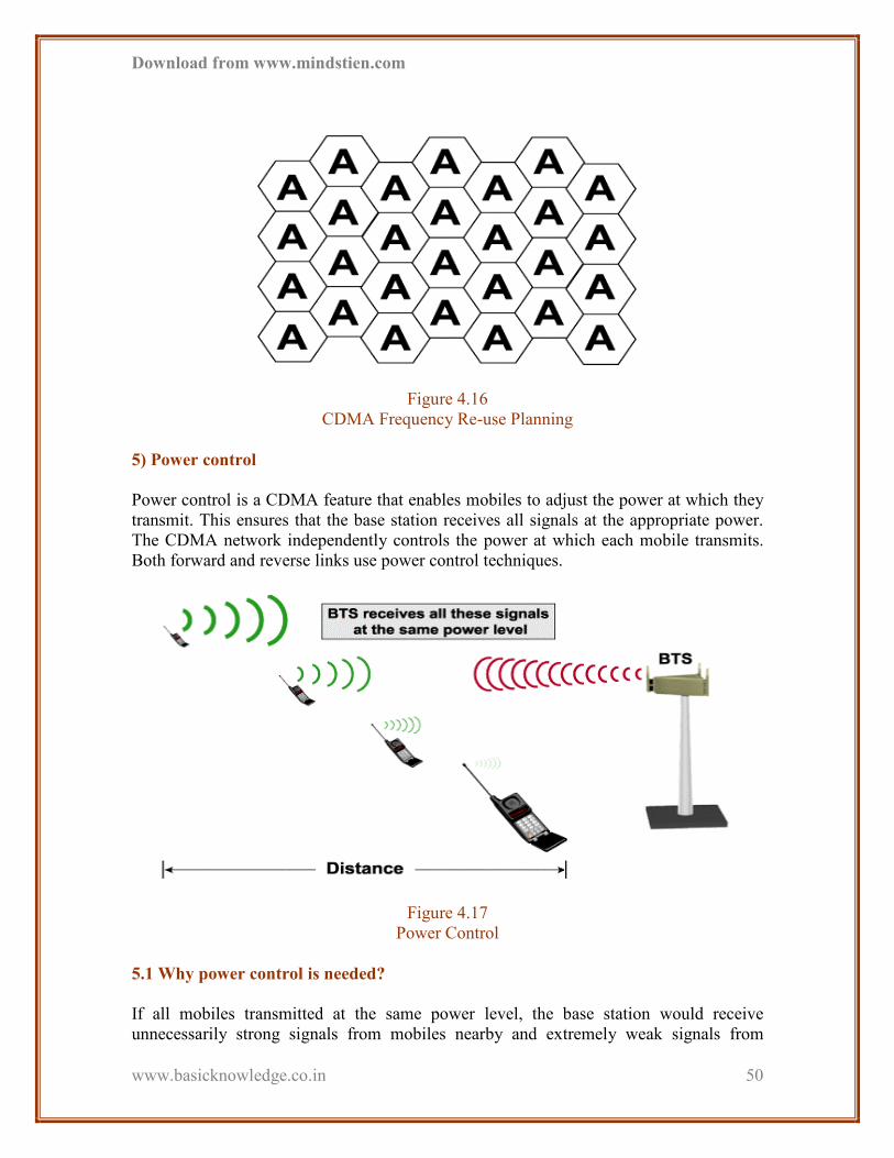
5) Power control
Power control is a CDMA feature that enables mobiles to adjust the power at which they
transmit. This ensures that the base station receives all signals at the appropriate power.
The CDMA network independently controls the power at which each mobile transmits.
Both forward and reverse links use power control techniques.
Figure 4.17
Power Control
5.1 Why power control is needed?
If all mobiles transmitted at the same power level, the base station would receive
unnecessarily strong signals from mobiles nearby and extremely weak signals from

Download from www.mindstien.com
www.basicknowledge.co.in
51
mobiles that are far away. This would reduce the capacity of the system. This problem is
called the near-far problem.
Figure 4.18
Need For Power Control
5.2 Reverse link power control
Reverse link power control consists of two processes:
5.2.1 Open loop power control
5.2.2 Closed loop power control
Open loop is an initial estimate of the power the mobile needs to transmit to the BTS.
Closed loop is a refinement of the open loop estimate.
5.2.1 Open loop power control
Open loop is the mobile's estimate of the power at which it should transmit. The open
loop estimate is based on the strength of the pilot signal the mobile receives. As the pilot
signal gets weaker or stronger, the mobile adjusts its transmission strength upwards or
downwards. Open loop is used any time the mobile transmits

Download from www.mindstien.com
www.basicknowledge.co.in
52
Figure 4.19
Open Loop Power Control
5.2.2 Closed loop power control
In closed loop, the BTS sends a command to the mobile to increase or decrease the
strength at which it is transmitting. The BTS determines this command based on the
quality of the signal it receives from the mobile. Closed loop is only used during a call.
Closed loop commands are sent on the forward traffic channel.
Figure 4.20
Close Loop Power Control
5.3 Forward link power control
The BTS independently adjusts the power for each forward traffic channel based on the
information it receives from the mobile.
Download from www.mindstien.com
www.basicknowledge.co.in
53
Figure 4.21
Forward Link Power Control
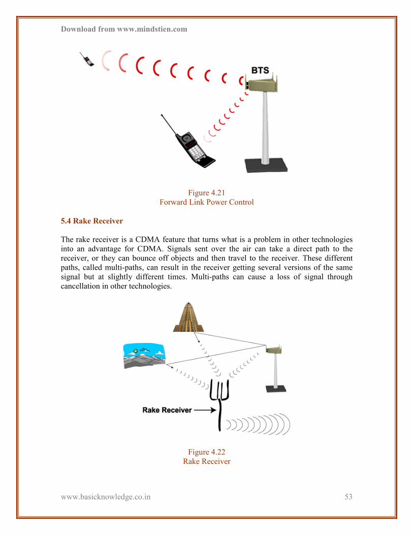
5.4 Rake Receiver
The rake receiver is a CDMA feature that turns what is a problem in other technologies
into an advantage for CDMA. Signals sent over the air can take a direct path to the
receiver, or they can bounce off objects and then travel to the receiver. These different
paths, called multi-paths, can result in the receiver getting several versions of the same
signal but at slightly different times. Multi-paths can cause a loss of signal through
cancellation in other technologies.
Figure 4.22
Rake Receiver

Download from www.mindstien.com
www.basicknowledge.co.in
54
CDMA's rake receiver is multiple receivers in one. The rake receiver identifies the three
strongest multi-path signals and combines them to produce one very strong signal. The
rake receiver therefore uses multipath to reduce the power the transmitter must send.
Both the mobile and the BTS use rake receivers.
4.6 Handoff in CDMA
Handoff is the process of transferring a call from one cell to another. This is necessary to
continue the call as the phone travels. CDMA is unique in how it handles handoff.
CDMA has three primary types of handoff:
1) CDMA Soft handoff
2) CDMA Hard handoff
3) CDMA Idle handoff
The type of handoff depends on the handoff situation.
1) CDMA Soft handoff
A soft handoff establishes a connection with the new BTS prior to breaking the
connection with the old one. This is possible because CDMA cells use the same
frequency and because the mobile uses a rake receiver. The CDMA mobile assists the
network in the handoff. The mobile detects a new pilot as it travels to the next coverage
area. The new base station then establishes a connection with the mobile. This new
communication link is established while the mobile maintains the link with the old BTS.
Soft handoffs are also called "make-before-break."

Download from www.mindstien.com
www.basicknowledge.co.in
55
Figure 4.23
CDMA Soft Handoff
• Variations of the soft handoff
There are two variations of soft handoffs involving handoffs between sectors within a
BTS:
1.1 Softer
1.2 Soft-softer
The softer handoff occurs between two sectors of the same BTS. The BTS decodes and
combines the voice signal from each sector and forwards the combined voice frame to the
BSC. The soft-softer handoff is combination handoff involving multiple cells and
multiple sectors within one of the cells.

Download from www.mindstien.com
www.basicknowledge.co.in
56
Figure 4.24
CDMA Softer Handoff
2) CDMA hard handoff
A hard handoff requires the mobile to break the connection with the old BTS prior to
making the connection with the new one. CDMA phones use a hard handoff when
moving from a CDMA system to an analog system because soft handoffs are not possible
in analog systems. A Pilot Beacon Unit (PBU) at the analog cell site alerts the phone that
it is reaching the edge of CDMA coverage. The phone switches from digital to analog
mode as during the hard handoff. Hard handoffs are also called "break-before-make."
Figure 4.25
CDMA Hard Handoff
Download from www.mindstien.com
www.basicknowledge.co.in
57
The CDMA hard handoff may be used when moving from a CDMA network to an analog
one. It may also be used when moving to a different:
• RF channel
• MTSO
• Carrier
• Market
Analog to CDMA handoff is not available due to the limitations of analog technology.
3) CDMA Idle handoff
An idle handoff occurs when the phone is in idle mode. The mobile will detect a pilot
signal that is stronger than the current pilot. The mobile is always searching for the pilots
from any neighboring BTS. When it finds a stronger signal, the mobile simply begins
attending to the new pilot. An idle handoff occurs without any assistance from the BTS.
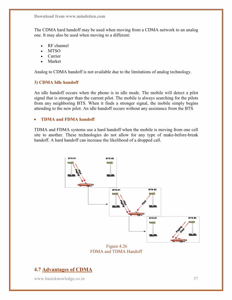
• TDMA and FDMA handoff
TDMA and FDMA systems use a hard handoff when the mobile is moving from one cell
site to another. These technologies do not allow for any type of make-before-break
handoff. A hard handoff can increase the likelihood of a dropped call.
Figure 4.26
FDMA and TDMA Handoff
4.7 Advantages of CDMA
Download from www.mindstien.com
www.basicknowledge.co.in
58
1) Coverage
CDMA's features result in coverage that is between 1.7 and 3 times that of TDMA:
� Power control helps the network dynamically expand the coverage area.
o Coding and interleaving provide the ability to cover a larger area for the same
amount of available power used in other systems.
2) Capacity
CDMA capacity is ten to twenty times that of analog systems, and it's up to four times
that of TDMA. Reasons for this include:
� CDMA's universal frequency reuse
� CDMA users are separated by codes, not frequencies
� Power control minimizes interference, resulting in maximized capacity.
� CDMA's soft handoff also helps increase capacity. This is because a soft handoff
requires less power.
3) Clarity
Often CDMA systems can achieve "wire line" clarity because of CDMA's strong digital
processing. Specifically:
� The rake receiver reduces errors
� The variable rate vocoder reduces the amount of data transmitted per person,
reducing interference.
� The soft handoff also reduces power requirements and interference.
� Power control reduces errors by keeping power at an optimal level.
� CDMA's wide band signal reduces fading.
� Encoding and interleaving reduce errors that result from fading
4) Cost
CDMA's better coverage and capacity result in cost benefits:
� Increased coverage per BTS means fewer are needed to cover a given area. This
reduces infrastructure costs for the providers.
� Increased capacity increases the service provider's revenue potential.
� CDMA costs per subscriber have steadily declined since 1995 for both cellular
and PCS applications.
5) Compatibility

Download from www.mindstien.com
www.basicknowledge.co.in
59
CDMA phones are usually dual mode. This means they can work in both CDMA systems
and analog cellular systems. Some CDMA phones are dual band as well as dual mode.
They can work in CDMA mode in the PCS band, CDMA mode in the cellular band, or
analog mode in an analog cellular network.
6) Customer satisfaction
CDMA results in greater customer satisfaction because CDMA provides better:
• Voice quality
• Longer battery life due to reduced power requirements
• No cross-talk because of CDMA's unique coding
• Privacy--again, because of coding.
7) Wireless local loop (WLL)
Wireless local loop phones in homes, offices or even boats connect with a wireless
system in a manner similar to that of CDMA cell phones. The difference is that WLL
phones usually stay in a relatively fixed location. WLL phones often connect to AC
current rather than using batteries. They can be used to provide voice, fax, and data
connections.
Figure 4.27
Wireless Local Loop (WLL)
4.8 Site Structure

Download from www.mindstien.com
www.basicknowledge.co.in
60
The basic structure of the network is shown in the figure. The components are described
below:
1) Microwave Antenna
2) ODU (Out Door Unit)
3) IDU (In Door Unit)
4) MUX
5) DDF (Digital Distribution Frame)
6) BTS (Base station Transceiver Subsystem)
7) Sector antenna
8) GPS antenna
1) Microwave antenna
MW antenna is used to transmit MW signal in air. This antenna is a directional antenna
(DA). It means it will transmit in one direction only. This is used to connect E1 link
between two sites. Two MW antennas are there in each site to establish a ring network. It
sends traffic to BSC (Base Station Controller). The transmitting frequency is in terms of
GHz. Parabolic types of antenna are used in TTSL.
2) ODU (Out Door Unit)
ODU is attached to the MW antenna. Its function is to modulate the incoming signal
from IDU with higher carrier frequency signal. Means frequency up conversion is
performed here.
3) IDU (In Door Unit)
IDU converts between RF (Radio Frequency) signal and optical signal. To establish ring
network more then one IDU can be required.
4) MUX
Here MUX are used to carry E1 from one site to the other site. BTS is connected to the
MUX via DDF. Here MUX can carry both data and voice traffic. MUX uses SDH
(Synchronous Digital Hierarchy) technology. Different types are:
Type Capacity Data Rate
STM-0 21E1 51.54 Mbps
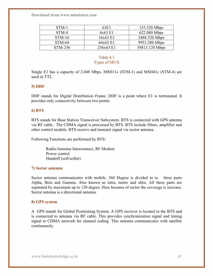
Download from www.mindstien.com
www.basicknowledge.co.in
61
STM-1 63E1 155.520 Mbps
STM-4 4x63 E1 622.080 Mbps
STM-16 16x63 E1 2488.320 Mbps
STM-64 64x63 E1 9953.280 Mbps
STM-256 256x63 E1 39813.120 Mbps
Table 4.1
Types of MUX
Single E1 has a capacity of 2.048 Mbps. MSH11c (STM-1) and MSH41c (STM-4) are
used in TTL.
5) DDF
DDF stands for Digital Distribution Frame. DDF is a point where E1 is terminated. It
provides only connectivity between two points.
6) BTS
BTS stands for Base Station Transceiver Subsystem. BTS is connected with GPS antenna
via RF cable. The CDMA signal is processed by BTS. BTS include filters, amplifier and
other control module. BTS receive and transmit signal via sector antenna.
Following Functions are performed by BTS:
Radio/Antenna Interconnect, RF Modem
Power control
Handoff (soft/softer)
7) Sector antenna
Sector antenna communicates with mobile. 360 Degree is divided in to three parts
Alpha, Beta and Gamma. Also known as intra, metro and ultra. All three parts are
separated by maximum up to 120 degree. Here because of sector the coverage is increase.
Sector antenna is a directional antenna.
8) GPS system
A GPS stands for Global Positioning System. A GPS receiver is located in the BTS and
is connected to antenna via RF cable. This provides synchronization signal and timing
signal to CDMA network for channel coding. This antenna communicates with satellite
continuously.
Download from www.mindstien.com
www.basicknowledge.co.in
62
CHAPTER 5
PDH – SDH
FUNDAMENTALS
5.1 Plesiochronous Digital Hierarchy
5.2 Dis-Advantages of PDH
5.3 Why SDH?
5.4 SDH Frame Architecture
5.5 Overhead Analysis
5.6 Virtual Container
5.1 Plesiochronous Digital Hierarchy
Plesio means = similar
Chronous means= Timing

Download from www.mindstien.com
www.basicknowledge.co.in
63
Plesiochoronous - "almost synchronous, because bits are stuffed into the frames as
padding and the calls (signal) location varies slightly - jitters - from frame to frame".
The basis of analog to digital conversion is Shannon’s theory. The theory states that after
transmission the original signal can be reproduced within certain limits from digital
signal obtained by Sampling an analog at regular intervals and at a rate at least twice the
highest significant message frequency.
5.2 Disadvantages of PDH
Plesiochoronous Hierarchy based on 2Mbps primary rates permits multiplexing up to
140Mbps respectively.
• Changing from one hierarchical level to another requires additional equipment.
• Transmitting a multiplexed signal (34/140 Mb, etc) requires specialized
equipment.
• Redirection (cross-connection) of channels must be done by hand on DDFs.
• Administrative connections require separate equipment to support Supervision,
EOW and protection switching.
• Compatibility of transmission and administrative signals between different
vendors may give trouble.
Figure 5.1
Pre-SDH (System Monitoring Only)
5.3 Why SDH Require?
To cope up the demand of higher bit rate SDH technology is introduced.

Download from www.mindstien.com
www.basicknowledge.co.in
64
Figure 5.2
SDH (System Monitoring and Management Possible)
• Advantages of SDH over PDH
1) Higher Transmission rate
Transmission rate up to 10 Gbps can be achieved by the modern SDH system. SDH is
therefore considered to be more suitable for backbone.
2) Simplified Add/Drop function
Compared with older PDH system, it is much easier to insert and extract low bit rate
channels from or into the high-speed bit streams in SDH.
3) High availability and capacity matching
With SDH network providers can react quickly and easily to the requirements of their
customers.
4) Reliability
Modern SDH networks include various back-up and repair mechanisms to cope up with
system faults.
5) Interconnection
SDH makes it much easier to set up gateways between different network providers and to
SONET systems.

Download from www.mindstien.com
www.basicknowledge.co.in
65
5.4 SDH frame Architecture
A frame with a bit rate of 155.52 Mbps is defined in ITU-T recommendation G.707. This
frame is called synchronous Transport Module (STM), since it is first level in hierarchy it
is called STM-1.
It is made up from a byte matrix of 9 rows and 270 columns.
Transmission is row by row, starting with the byte in the upper left corner and ending
with the byte in the lower right corner.
The frame repetition rate is 125us. Each byte in the payload represents a 64 kbps channel.
Figure 5.3
SDH Frame Structure-A
PAYLOAD CONTAINER 9 (Rows) * 260 (Column) * 64Kbps = 149.76 Mbps
POH 9 (Rows) * 1 (Column) * 64 Kbps = 0.576Mbps
RSOH 3 (Rows) * 9 (Columns) * 64 Kbps = 1.728 Mbps
MSOH 5 (Rows) * 9 (Columns) * 64 Kbps = 2.880 Mbps
Table 5.1
SDH Frame Architecture
1) How Is The Frame Composed? PDH Payload = Container (C)
Container + Path Overhead (POH) = Virtual Container (VC)
PAYLOAD CONTAINER
P
O
H
RSOH
POINTER
MSOH
1
3
4
9
1 9 10 270

Download from www.mindstien.com
www.basicknowledge.co.in
66
Virtual Container + TU Pointer = Tributary Unit (TU)
More than 1 Tributary Unit = Tributary Unit Group (TUG)
Biggest Tributary Unit Group = Administrative Unit (AU)
Tributary Unit Group + AU Pointer = Administrative Unit (AU)
More than 1 Administrative Unit = Administrative Unit Group
Administrative Unit Group + Section Overhead (SOH) = SDH Frame
Figure 5.4
SDH Hierarchy – TUG Structure
2) PDH: Plesiochoronous Digital Hierarchy (PDH) consists of E1, E2, E3 and E4
communication standard.
3) SDH
It is a high speed – high capacity optical telecommunication network.
C-12 VC-12 TU-12
C-3 VC-3 TU-3
C-4 VC-4
AU-4
STM-
1
X 3
POINTER
MULTIFLEXING
ADDITION OF VERHEADS
ALIGNMEN
TUG
-2
TUG
-3

Download from www.mindstien.com
www.basicknowledge.co.in
67
Plesiochoronous multiplexing technology left no room in the signal structure for network
management and maintenance functions. In a Plesiochoronous network accessing one
individual tributary req the whole signal to be demultiplexed.
Synchronous Digital Hierarchy (SDH) consists of STM-1, STM-4, STM-16 and STM-64.
SDH overcomes the problems of Plesiochoronous networks.
The lowest level SDH signal is called the “Synchronous Transport Module”
SDH line rates.
STM – 1 155.52 Mbps
STM – 4 622.08 Mbps
STM – 16 2488.32 Mbps
SDH is a technology which supports a single telecommunication network infrastructure
based on synchronous multiplexing.
SONET in North America is equivalent of SDH. The STM – 4 also have 9 rows but have
1080 columns. 4 STM – 1 can be multiplexed up to STM – 4.
4) Frame structure
Figure 5.5
SDH Frame Structure-B

Download from www.mindstien.com
www.basicknowledge.co.in
68
Figure 5.6
STM-1 & STM-4 Frame Structure
5.5 Overhead analysis
The path overhead supports end-to-end management of the virtual container.
The multiplex section overhead is used to manage transmission between network nodes
i.e. between adjacent multiplexers and cross-connect switches.
The regenerators section overhead is used to manage transmission between regulators.
The bytes in the SDH frame are transmitted from left to right & top to bottom.

Download from www.mindstien.com
www.basicknowledge.co.in
69
Figure 5.7
Overhead Analysis
Figure 5.8
Bytes Transmitted in SDH Frame
5.6 Virtual Container
The virtual container is where the actual data is.
The VC is subdivided into smaller units like palettes or crates.
These are known as individual tributary units.
Examples of which are standard rates E1 and E3.
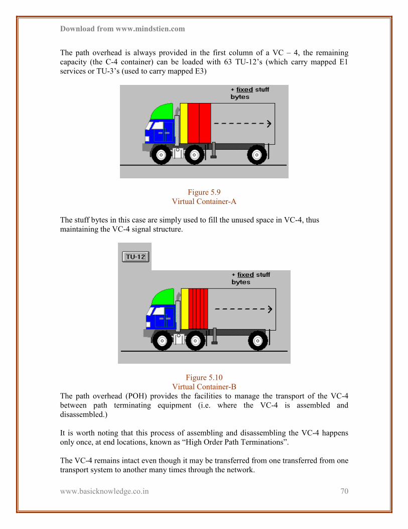
Download from www.mindstien.com
www.basicknowledge.co.in
70
The path overhead is always provided in the first column of a VC – 4, the remaining
capacity (the C-4 container) can be loaded with 63 TU-12’s (which carry mapped E1
services or TU-3’s (used to carry mapped E3)
Figure 5.9
Virtual Container-A
The stuff bytes in this case are simply used to fill the unused space in VC-4, thus
maintaining the VC-4 signal structure.
Figure 5.10
Virtual Container-B
The path overhead (POH) provides the facilities to manage the transport of the VC-4
between path terminating equipment (i.e. where the VC-4 is assembled and
disassembled.)
It is worth noting that this process of assembling and disassembling the VC-4 happens
only once, at end locations, known as “High Order Path Terminations”.
The VC-4 remains intact even though it may be transferred from one transferred from one
transport system to another many times through the network.

Download from www.mindstien.com
www.basicknowledge.co.in
71
Figure 5.11
The Completed Virtual Container-4
1) Virtual Container Capacity
The STM-1 frame is made up of 270 columns 9 rows of 8 bytes. There is a frame
repetition rate of 8000 Hz.
This gives us a total of
270 * 9 * 8 * 8000 = 155.52 Mbps
However 9 columns are used as section overhead, leaving us with the VC-4 capacity
261 * 9 * 8 * 8000 = 150.33 Mbps
1 column is used for the Path Overhead, so actual payload capacity (C-4) of the VC-4 is
260 * 9 * 8 * 8000 = 149.76 Mbps
Actual customer data is transported in the payload area of the Virtual Container (e.g. C-4
is the ‘Container’ of a VC-4.)
Figure 5.12

Download from www.mindstien.com
www.basicknowledge.co.in
72
Virtual Container Capacity-A
The container can be split up into Tributary units which are like palettes to be loaded onto
our trucks.
The Virtual Container is completed by adding the Path Overhead which is like a baggage
label for our container.
Figure 5.13
Virtual Container Capacity-B
The VC-4 is allowed to start at any position within the payload area. Most often it begins
in one frame and ends in another. This ability of the VC-4 to move relative to STM frame
is known as ‘floting’.
It is important to understand the VC-4 can start at any byte location within the STM
frame’s payload area. No matter the start location the order of bytes within the VC-4
remains unchanged.
Different network operators will have their own independent master timing references.
These clocks will operate at slightly different rates.
SDH transport must therefore, be able of operate effectively between network nodes
which are operating asynchronously.
Pointers are used to
1. Compensate for frequency offsets between a received STM-N signal and the
network element’s clock.
2. Identify the location of individual VCs for efficient cross connecting and
demultiplexing.
2) Sub STM-1 Payloads
STM-1 payload (VC-4) was designed to provide transport for a 139 Mbps tributary
signal.

Download from www.mindstien.com
www.basicknowledge.co.in
73
Transport for a lower rate tributary signals, such as 2 Mbps is provided by a Tributary
Unit (TU) structure. The TU represents a mini frame with a fixed number of TUs
assembled within a VC-4.
3) Range of TUs
Each TU-12 frame consists of 36 bytes, structured as 4 columns of 9 bytes.
At a frame rate of 8000 Hz, these bytes provide a transport capacity of 2.304 Mbps
4 columns * 9 rows * 8 bits * 8000 frames/sec = 2.304 Mbps
This will accommodate the mapping of a 2.048 Mbps (E1) signal.
63 TU-12’s may be multiplexed into the VC-4.
4) TU packaging
How many TU-12 are carried in a VC-4?
The TU-12’s go through two levels of intermediate multiplexing before being loaded into
the VC-4. These intermediate multiplexing levels are known as Tributary Unit Groups
(TUG).
CHAPTER 6

Download from www.mindstien.com
www.basicknowledge.co.in
74
INTRODUCTION TO
MODCELL 1.0 BTS
6.1 BTS (Base Transceiver Station)
6.2 BTS Modules
6.3 Radio Link
Filters
Facilities
Interface
Module
(FIM)
Power Distribution
Assembly (PDA)

Download from www.mindstien.com
www.basicknowledge.co.in
75
Figure 6.1
Primary Outdoor Modcell 1.0
6.1 BTS (Base Transciever Station)
Base Transceiver System is the first node in the path of call flow from MS to MSC.
The basic structure of mobile network is as follows:
1) CDMA ANTENNAS
CDMA antennas are mounted on the tower according to the RF planning, which includes
height, electrical and mechanical tilt and the number of antennas.
The area is segmented in 120 degrees in three sectors with the aid of 3 antennas, which
are polarized +45 and -45 degrees.
Each antenna has 2 cables, a) Diversity cable for receiving signals and b) TRX i.e. Tx
and Rx cable which transfers the call request to BTS. This makes a total of 6 cables
emerging from the antenna and converging to BTS. The TRX cables go to the duplexers
and segregate the 3 Tx and Rx cables.
CTRM
Amplifier Fans
Smart Switch
Crystal OM (Xo)
ULAMs
Rubidium OM (Rb)
Digital Fans
CDM
1 CDM
2 CDM
3
Remote Maintenance
Panel (RMP)
Digital Module
(CCUs, CRCs,
CBRs, TFUs,
PCUs)
Fan Controller
ULAM Interface
Panel (UIP)
Type 1

Download from www.mindstien.com
www.basicknowledge.co.in
76
2) MOTOROLA BTS
The –48 Volt Motorola BTS can accommodate up to four separate carriers in a three-
sector configuration or up to two carriers in a six-sector configuration.
The TX base band path begins at the MCC card. The MCC card generates traffic channel
information, and data is routed to the BBX module for combining and filtering of
transmitted digital I and Q signals. Each MCC has a direct connection to each BBX. The
TX RF path begins at the output of the BBX modules. The BBX generates the CDMA RF
signal, which will be amplified by the CLPAs. A redundant BBX is combined with all
sectors and is automatically switched into service in the event of a primary BBX failure.
When a CCCP shelf includes a IS 2000 1X carrier, the BBX cards that support the
respective 1X sector carriers must be a BBX1X card, and the redundant BBX must be a
BBX1X. The BBX output is routed through the CIO card in the C–CCP cage to the
CLPA trunking backplane of each carrier via a cabled connection. The Trunked CLPA
Sets amplify the modulated transceiver transmit signal. The CLPA output connects to the
TX band pass filter, or cavity combiner modules and is routed to the TX antenna ports
(N-type connectors) on the I/O Panel at the top of the –48 Volt Motorola BTS frame. Up
to four sector carrier outputs can be combined together via cavity combiner(s) to
minimize the number of TX antennas.
For the –48 Volt Motorola BTS the RX signal path in the frame begins at the N–type RX
antenna inputs located on the I/O Panel at the top of the frame. The signals are routed
through the RX Tri–filters, located on the I/O Panel, to the Multicoupler Preselector cards
(MPC), or Expansion MPC (EMPC) on the C–CCP Shelf via coax. A frame is equipped
with two MPCs, one supporting the main signals and the other supporting the diversity
signals. The MPC module provides low noise amplification for the incoming RX signals.
The MPC outputs are routed to the Combiner Input/Output (CIO) card via the C–CCP
backplane and to the BBX cards. The CIO routes the RF receive signals to the expansion
connector and the respective BBX card or the BBX Switch cards, and provides the
expansion output.
6.2 BTS Modules
The –48 Motorola BTS CDMA frames contain all of the CDMA functions in the CCCP
Cage and the CDMA ST-CLPA Shelf. These functions are implemented in the modules
listed below:
1) C-CCP CAGE
• MCC24 or MCC-8E or MCC1X
• BBX2 or BBX1X
• GLI2
• CIO
• CSM w/RF GPS

Download from www.mindstien.com
www.basicknowledge.co.in
77
• CSM w/Remote GPS (Available with R9)
• CCD
• HSO
• AMR
• MPC or EMPC
• +27 Volt C-CCP Power Supply
• Switch Card
2) CDMA ST-CLPA SHELF
CDMA ST-CLPAs
• Trunking Module(s)
• Combiners/Filters
3) -48V POWER SUPPLY SYSTEM
• –48V Power Supply Module
• Power and Alarms Card (PAC)
4) +27 VOLT C-CCP CAGE
The single +27 Volt SC™4812T Combined CDMA Channel Processor (C-CCP) shelf
provides the span line interfaces, channel processing, shelf control, and CDMA
transceivers (purchased separately). The +27 Volt BTS C-CCP cage supports up to a total
of twelve sector carriers(e.g., 3-sector, 4-carrier or 6-sector, 2-carrier) and up to 576
Physical Channels (assuming use of MCC1X-48 cards). A fully loaded C-CCP shelf
houses 13 (one per sector per carrier with one redundant) Broad Band Transceiver boards
(BBX2s or BBX1X), 12 Multi- Channel CDMA cards (i.e., MCC1X or MCC-24 or
MCC-8E), one Switch card, two Group Line Interface-2 boards (GLI2), the Combiner
Input/Output (CIO) board, two Multi-Coupler Preselector (MPCs), two Alarm Module
Reporting (AMR) boards, two Clock Synchronization Manager (CSMs), the Rubidium
High Stability Oscillator (HSO), two Clock Distribution Modules (CCD), and two or
three power supply boards.
These are CCCP cage cards.
1. MPC 1, MPC 2
2. Power 1, Power 2, Power 3
3. BBX2 - Redundant Switch
4. MCC 1 to 12
5. HSO
6. BBX1 to 12
7. GLI -1 GLI -2
8. AMR-1 AMR-2
9. CSM 1, CSM 2

Download from www.mindstien.com
www.basicknowledge.co.in
78
10. CCD1/CCD2 11. Modem
1. The MCC card contains the circuitry necessary to implement CDMA channels of any
Type except the pilot.
• The MCC-1X cards contain the circuitry necessary to implement all the
1X channel types in IS-2000.
• For overhead channel redundancy, a three sectors or Omni configuration
requires a minimum of two MCCs, and a six-sector configuration requires
a minimum of three MCC cards. A C-CCP cage can be populated with up
to twelve MCC cards.
• If redundancy is required for the new IS-2000 channels, a minimum of
two MCC-1X cards will be required.
• For 6-sector BTS’s, the MCC-1X cards will need to be dedicated per
carrier.
2. The BBX provides the generation of the Pilot signal, the conversion from digital base
band to RF for the forward (transmit) link, and RF to digital base band for the reverse
(receive) link.
• Each BBX will support any single CDMA RF channel per sector at any
frequency in the IS-95 800 MHz frequency band at a cell site.
• The BBX is controlled by the Group Line Interface (GLI2) card via the
Concentration Highway Interface (CHI) within the CDMA Channel
Processor (C–CCP) backplane.
• The BBX receives clock and synchronization signals via the CCD from
the CSM.
• An Omni site requires one BBX2 or BBX1X card plus a redundant BBX2
or BBX1X card
• A 1 carrier, 3 sector site requires three BBX2 or BBX1X cards plus a
redundant BBX2 or BBX1X card
• A 2 carrier, 3 sector site requires six BBX2 or BBX1X cards plus a
redundant BBX2 or BBX1X card
• A 3 carrier, 3-sector site requires nine BBX2 or BBX1X cards plus a
redundant BBX2 or BBX1X card

Download from www.mindstien.com
www.basicknowledge.co.in
79
• A 4 carrier, 3-sector site requires twelve BBX2 or BBX1X cards plus a
redundant BBX2 or BBX1X card
• A 1 carrier, 6-sector site requires six BBX2 or BBX1X cards plus a
redundant BBX2 or BBX1X card
• A 2 carrier, 6-sector site requires twelve BBX2 or BBX1X cards plus a
redundant BBX2 or BBX1X card
3. The GLI2 card functions as the BTS controller and provides routing of traffic and
control information, and O&M functions for all active devices in the C-CCP cage. It is
the controller of the C-CCP cage and acts as a message router between the CBSC and the
BTS equipment.
4. The CSM (Clock Synchronization Manager) maintains CDMA system time and
generates the master clock and reference signals for other CDMA system modules.
• To provide the required synchronization for the CDMA frames, the CSM
can phase lock up to two types of sources, a GPS receiver, or the HSO.
• The GPS receiver is the primary source and the HSO is the redundant
source.
• The CSM generates three clock/synchronization signals, which are
distributed to the C-CCP cage.
5. The generation of the CDMA clock and synchronization signals is provided by the
CSM. The CSM generates the CDMA clock (19.6608 MHz), even-second reference and
the absolute time of day information.
• The CDMA clock and sync is routed to the C-CCP via the CCD (Clock
Distribution Subsystem).
• The CCD buffers the CDMA clock and sync and directs these signals out
to the MCCs, BBXs, and the GLIs. Each CSM is linked to one and only
one CCD card. The CCD card reports internal alarms back to its respective
CSM. In case of failure, the active CSM then seamlessly switches to the
redundant CSM and CCD pair.
6. The HSO (High Stability Oscillator) also is an optional card that provides backup for
the GPS.
• The HSO module is an alternate source of the synchronization and
absolute time information that is required at a CDMA BTS.
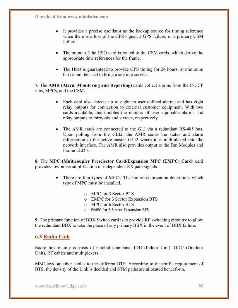
Download from www.mindstien.com
www.basicknowledge.co.in
80
• It provides a precise oscillator as the backup source for timing reference
when there is a loss of the GPS signal, a GPS failure, or a primary CSM
failure.
• The output of the HSO card is routed to the CSM cards, which derive the
appropriate time references for the frame.
• The HSO is guaranteed to provide GPS timing for 24 hours, at minimum
but cannot be used to bring a site into service.
7. The AMR (Alarm Monitoring and Reporting) cards collect alarms from the C-CCP
fans, MPCs, and the CSM.
• Each card also detects up to eighteen user-defined alarms and has eight
relay outputs for connection to external customer equipment. With two
cards available, this doubles the number of user equipable alarms and
relay outputs to thirty-six and sixteen, respectively.
• The AMR cards are connected to the GLI via a redundant RS-485 bus.
Upon polling from the GLI2, the AMR sends the status and alarm
information to the active-master GLI2 where it is multiplexed into the
network interface. The AMR also provides output to the Fan Modules and
Frame LED’s.
8. The MPC (Multicoupler Preselector Card/Expansion MPC (EMPC) Card) card
provides low-noise amplification of independent RX path signals.
• There are four types of MPCs. The frame sectorization determines which
type of MPC must be installed.
o MPC for 3 Sector BTS
o EMPC for 3 Sector Expansion BTS
o MPC for 6 Sector BTS o EMPC for 6 Sector Expansion BTS
9. The primary function of BBX Switch card is to provide RF switching circuitry to allow
the redundant BBX to take the place of any primary BBX in the event of BBX failure.
6.3 Radio Link
Radio link mainly consists of parabolic antenna, IDU (Indoor Unit), ODU (Outdoor
Unit), RF cables and multiplexers.
MSC lays out fiber cables to the different BTS. According to the traffic requirement of
BTS, the density of the Link is decided and STM paths are allocated henceforth.
Download from www.mindstien.com
www.basicknowledge.co.in
81
The connectivity can be 1) Microwave or 2) Fiber. Microwave can be either PDH or SDH
while Fiber is having STM standard.
The call which originates from MS travels through BTS, for modulation, channel
allocation and synchronization, and enters IDU via BTS E1 cable link.
The call then flows from the main path, which is pre-decided. If it is fiber link it will go
through the same connectivity to MSC and if it is microwave then it will pass through
ODU via RF cables, which will further be passed to parabolic antennas and then
transmitted to the next link.
In case of fiber link, Optical Multiplexers are used so as to convert the Optical signal to
Electrical signal and vice-versa.
CHAPTER 7
BASIC MICROWAVE
RADIO SYSTEM

Download from www.mindstien.com
www.basicknowledge.co.in
82
7.1 Introduction
7.2 Advantages and Disadvantage of
Microwave
7.3 Wave Propagation
7.4 Fresznel zone
7.5 Surveying
7.6 Microwave Antenna
7.7 Free space loss & power budget
7.8 Precipitation
7.9 Fading margin
7.10 Diversity
7.11 Error performance & object
Availability
7.1 Introduction
In recent, there are no. of ways to communicate within network. Mostly it dependents on
which type of technology we use. There are some medium which listed below.
WAYS OF Communication Telecom industry:
1. Cable
2. Microwave radio
3. Optical fiber
4. Satellite
7.2 Advantages and Disadvantage of Microwave
1) Advantages of Microwave
1. Easy installation
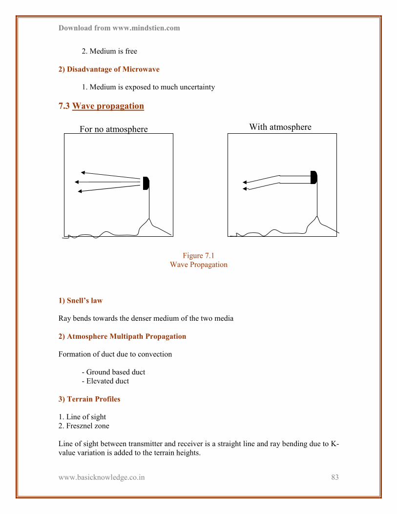
Download from www.mindstien.com
www.basicknowledge.co.in
83
2. Medium is free
2) Disadvantage of Microwave
1. Medium is exposed to much uncertainty
7.3 Wave propagation
Figure 7.1
Wave Propagation
1) Snell’s law
Ray bends towards the denser medium of the two media
2) Atmosphere Multipath Propagation
Formation of duct due to convection
- Ground based duct
- Elevated duct
3) Terrain Profiles
1. Line of sight
2. Fresznel zone
Line of sight between transmitter and receiver is a straight line and ray bending due to K-
value variation is added to the terrain heights.
With atmosphere For no atmosphere

Download from www.mindstien.com
www.basicknowledge.co.in
84
The modification of terrain heights is given by (d1.d2) / (12.74.k), where
k=1.33 for (5 to 15 kms) and 0.6 for longer path lengths (15-30 kms)
There must be a clearance for the first Fresznel zone to avoid diffraction loss in addition
to free space loss.
7.4 Fresznel zone
First Fresznel zone is defined as the locus of Points having maximum energy lobe from
Transmitter.
Antenna to Receiver Antenna
d3 - (d1+d2) = λ/2, where d3 = D1 + D2 refer to figure.
λ = wavelength
Figure 7.2
Fresznel Zone
For practical application the radius F1
May be approximated by the formula:
F1=17.3 (d1.d2/f.d), where f is the freq in GHz
D=d1+d2 the total path length in km
7.5 Surveying
1) Field work
1. Confirmation of LOS (checking critical obstacles)
2. Verification of position and altitudes of the sites
3. Soil investigation
4. Checking of site, road access
5. Availability of power (Exiting shelters and towers)
6. Propagation condition
7. Make interference measurements
8. Finally prepare a report with required optimum tower heights
F1
d1
D1 D2
d2

Download from www.mindstien.com
www.basicknowledge.co.in
85
2) Difficult areas for Microwave link
1. Over water paths
2. High reflection coefficient.
3. High ducting probability.
4. Rice and wheat fields
5. Strong ground reflection
6. Desert area
7. Multipath fading
8. Hot and Humid coastal areas
9. High ducting probability
7.6 Microwave Antennas
The parabolic Antenna is the most commonly used antenna in Microwave Radio-relay
systems.
1) Antenna parameters
1. Antenna gain
Gain is approximated by the formulae,
Gain = 17.8 + 20 log (D.f) dBi
Where D = Antenna diameter [m], f = Frequency in GHz
2. VSWR
Standard type Antenna 1.06 to 1.15 typically
High performance Antenna 1.04 to 1.06 typically
3. Cross polarization
A good cross-polarization enables full utilization of the frequency band by using.
4. Beam width
The half power beam width of an antenna is defined as the angular width of the main
beam at – 3 dB point.
7.7 Free space loss and Power Budget
Power received at any point from a radiated antenna is inversely proportional to square of
distance between them and radiating frequency.
It can be defined by formula:
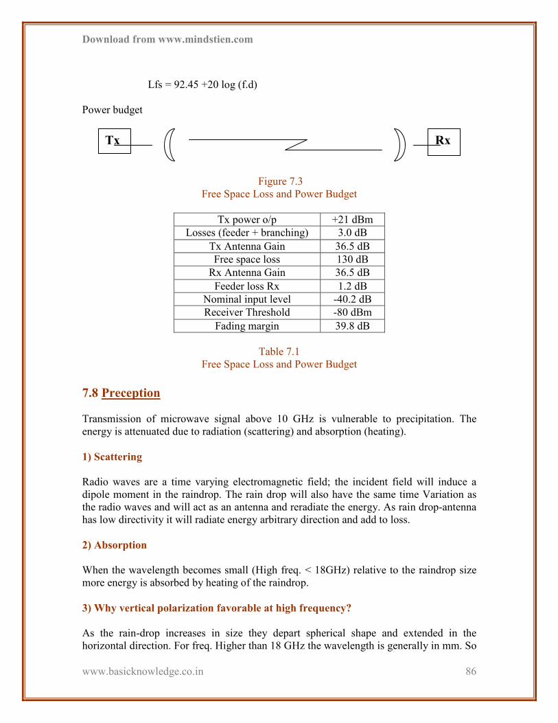
Download from www.mindstien.com
www.basicknowledge.co.in
86
Lfs = 92.45 +20 log (f.d)
Power budget
Figure 7.3
Free Space Loss and Power Budget
Tx power o/p +21 dBm
Losses (feeder + branching) 3.0 dB
Tx Antenna Gain 36.5 dB
Free space loss 130 dB
Rx Antenna Gain 36.5 dB
Feeder loss Rx 1.2 dB
Nominal input level -40.2 dB
Receiver Threshold -80 dBm
Fading margin 39.8 dB
Table 7.1
Free Space Loss and Power Budget
7.8 Preception
Transmission of microwave signal above 10 GHz is vulnerable to precipitation. The
energy is attenuated due to radiation (scattering) and absorption (heating).
1) Scattering
Radio waves are a time varying electromagnetic field; the incident field will induce a
dipole moment in the raindrop. The rain drop will also have the same time Variation as
the radio waves and will act as an antenna and reradiate the energy. As rain drop-antenna
has low directivity it will radiate energy arbitrary direction and add to loss.
2) Absorption
When the wavelength becomes small (High freq. < 18GHz) relative to the raindrop size
more energy is absorbed by heating of the raindrop.
3) Why vertical polarization favorable at high frequency?
As the rain-drop increases in size they depart spherical shape and extended in the
horizontal direction. For freq. Higher than 18 GHz the wavelength is generally in mm. So
Tx Rx

Download from www.mindstien.com
www.basicknowledge.co.in
87
these rain-drops attenuate horizontally polarized waves than the vertical Polarized.
Raindrop shapes
Figure 7.4
Vertical Polarization
7.9 Fading Margin
Figure 7.5
Fading Margin
Fading events are mainly caused by multipath fading and fading due to precipitation. So
larger the fading margin better the system performance.
This can be achieved by higher Tx o/p, larger (Gain) antennas, lower threshold level and
reduced path length etc.
1) Multipath Fading
Fading due to layering of the atmosphere is the dominating factor of degradation of radio-
relays transmitted waves that receives at the receiver refracted from the troposphere or
reflected from the ground other than wanted signals are added to it. The phase and
amplitude relationship determines the resulting I/p signal at the receiver.
1. Flat fading
2. Selective fading
7.10 Diversity
The common forms of diversity in LOS link frequency and space or combination of both.
Lately angle diversity is also introduced.
1) Space Diversity
Rx
I/P
Level
-40dBm
-80dBm Outage
Receiver
Threshold
Atmospheric
Disturbance
1mm 1.5mm 2mm 2.5mm
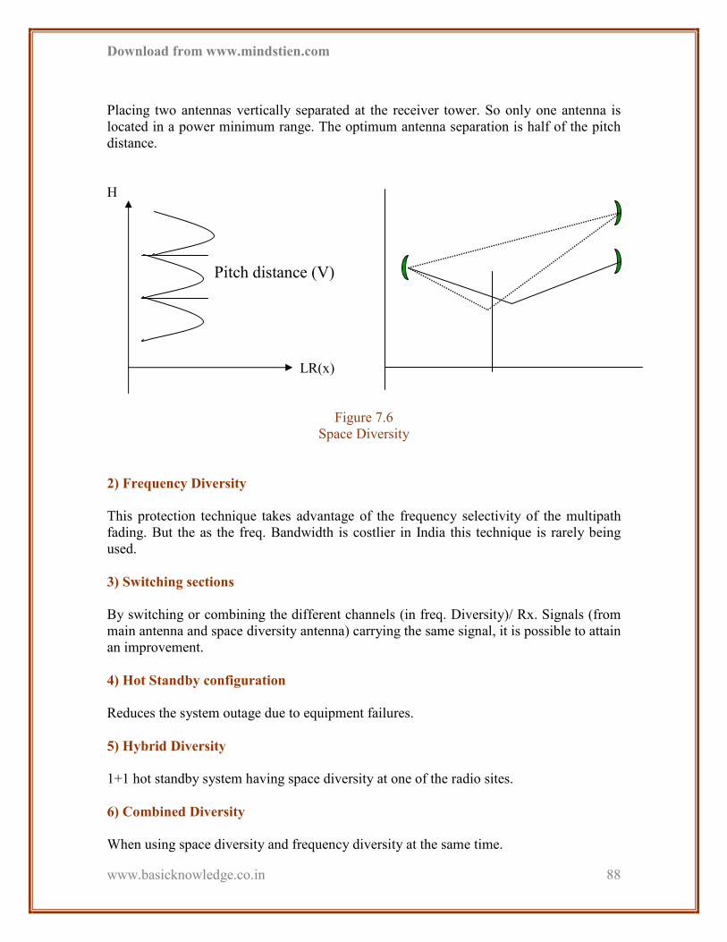
Download from www.mindstien.com
www.basicknowledge.co.in
88
Placing two antennas vertically separated at the receiver tower. So only one antenna is
located in a power minimum range. The optimum antenna separation is half of the pitch
distance.
H
LR(x)
Figure 7.6
Space Diversity
2) Frequency Diversity
This protection technique takes advantage of the frequency selectivity of the multipath
fading. But the as the freq. Bandwidth is costlier in India this technique is rarely being
used.
3) Switching sections
By switching or combining the different channels (in freq. Diversity)/ Rx. Signals (from
main antenna and space diversity antenna) carrying the same signal, it is possible to attain
an improvement.
4) Hot Standby configuration
Reduces the system outage due to equipment failures.
5) Hybrid Diversity
1+1 hot standby system having space diversity at one of the radio sites.
6) Combined Diversity
When using space diversity and frequency diversity at the same time.
Pitch distance (V)

Download from www.mindstien.com
www.basicknowledge.co.in
89
7.11 Error Performance and object Availability
These are based on the definition of the network for different microwave systems.
ITU-T and ITU-R recommendations.
G.801, G.821 and G.826
1) Some Definitions
1. SES
A BER of (10)¯³ is measures with an integration time of one second. BER of (10)¯³ is the
point where the signal is unacceptable to most of services.
2. ES
An ES is a second that contains at least one error. ES may result from causes other than
fading.
3. DM
A BER of 10¯6 is measure with an integration time of one minute.
4. Unavailable Time
If the 10 consecutive seconds are SES than that period is Unavailable period/Time.
2) Performance objectives (G.821 [2])
SES 0.2 % of one second interval in any month.
DM 10 % of one minute intervals in any month.
ES 8% of one second intervals of any errors.
Download from www.mindstien.com
www.basicknowledge.co.in
90
CHAPTER 8
PRACTICAL WORK

Download from www.mindstien.com
www.basicknowledge.co.in
91
1) Everyday at 9.30 am I have to go company & start my training by visiting
different site in Ahmedabad city. Some cities of North Gujarat.
2) At that site I do some work like:
• Alarms checking
• Cable routing
• E1 patching / removing
• Checking connectivity between IDU & ODU
• Replace the LPA
• To insert login cable & check link to other site
• Antenna alignment
• Make site in working condition
3) Types of Alarms:
Alarms -1. Minor: - No incoming signal
2. Major: - No outgoing signal
3. OMU block
4) At the Science City we have to install the Cow BTS. At there first install CDMA
antenna and then install the Microwave antenna. And alignment nearest
Microwave antenna.
5) We have to replace the faulty LPA and install the new LPA at Kalupur Chokha
Bazaar. And unlock LPA by the MSC at S.G.Highway.

Download from www.mindstien.com
www.basicknowledge.co.in
92
6) Power plant & Battery bank installation at SHAPATH due to loss of voltage.
7) Went to the site, Viramgam, to route traffic. Connect the higher capacity
multiplexer [XDM-500] & Disconnect the cable from [XDM-100].
8) Connect the higher capacity multiplexer in SR-HOUSE.
9) Survey of line of sight of nearer BTS at Santej, Shymal using GPS system
10) We went to NEWYORK TOWER, SG Highway there TTSL provides wireless
Services. It has intercom in ford show room. By using PRI meter we detected the
signal from BTS the line was clear. The problem was in EPBX (switching).
11) We have to replace the faulty LPA and install the new LPA at Narol. And unlock
LPA by the MSC at S.G.Highway.
12) AT NANO project, science city install COW BTS, first install CDMA antenna,
and MW link antenna, also alignment nearer MW antenna (BTS).
13) Visited at Paldi given DC power supply (-48 v), purpose standby Ethernet line
(FOC line) in DLC.
14) At some site I have (Juhapura, Nawab complex) done antenna TILTING
(Electrical & Mechanical alignment) to solve the coverage problem.
15) With help of OTDR (Optical Time Domain Reflectometer) we can locate the
OPTICAL fault within particular FIBRE link by radiating LASER from the
source.
16) We have done a VSWR measurement at VRUDAVAN SHOPPING CENTRE at
Manekchawk.
17) To give the INTERCOM facilities at CAMBAY I have check LOS by using GPS
device.
18) Mandali CDMA antenna was replaced. At site, BTS alarm cable replaced.
19) We have to Patching the E1 at the MUX at the kalash due to a guidance of the sir.
For that we have to use kronch. And also hoe that the E1 is dropped that we have
to check at there.
20) At Kalash sir gives us the knowledge of the MUX, E1.
21) We have also replaced the Cards at the different sites.

Download from www.mindstien.com
www.basicknowledge.co.in
93
22) At Kalash O&M department we observe that which company instrument that
TTSL used.