Embed Size (px)
Citation preview

Taser X2 Preliminary Investigation
Joey R. Bray, Department of Electrical and Computer Engineering Royal Military College of Canada Scientific Authority: Donna Wood DRDC Centre for Security Science The scientific or technical validity of this Contract Report is entirely the responsibility of the Contractor and the contents do not necessarily have the approval or endorsement of Defence R&D Canada.
Defence R&D Canada – Centre for Security Science DRDC CSS CR 2013-001 March 2013

Taser X2 Preliminary Investigation
Joey R. Bray, Department of Electrical and Computer Engineering Royal Military College of Canada Scientific Authority: Donna Wood DRDC Centre for Security Science The scientific or technical validity of this Contract Report is entirely the responsibility of the Contractor and the contents do not necessarily have the approval or endorsement of Defence R&D Canada.
Defence R&D Canada – Centre for Security Science DRDC CSS CR 2013-001

Principal Author
Original signed by Joey Bray
Joey Bray
Associate Professor, Professional Engineer
Approved by
Original signed by Donna Wood
Donna Wood
Project Manager
Approved for release by
Original signed by Dr. Mark Williamson
Mark Williamson
DRDC CSS DRP Chair
This work was sponsored as part of the Conducted Energy Weapons Strategic Initiative (CEWSI), project number 32bj, managed by Defence Research and Development Canada (DRDC) under the Centre for Security Sciences (CSS).
© Her Majesty the Queen in Right of Canada, as represented by the Minister of National Defence, 2013
© Sa Majesté la Reine (en droit du Canada), telle que représentée par le ministre de la Défense nationale, 2013
DRDC CSS CR 2013-001 i
Abstract ……..
This document describes the physical properties and explains the principles of operation of the Taser X2 conducted energy weapon produced by Taser International. The document also describes hardware and software accessories associated with the weapon. The measured electrical conducted waveforms of a Taser X2 are also documented herein, as are a number of technical observations regarding the operation of the Taser X2. Conclusions and recommendations are provided.
Résumé ….....
Ce document décrit les propriétés physiques et explique les principes de fonctionnement de l'arme à impulsions modèle Taser X2 produit par Taser International. Le document décrit aussi les accessoires matérielles et logicielles associées à l'arme. Les mesures électriques des ondes menées d'un Taser X2 sont également documentées ici, ainsi que certaines observations techniques concernant le fonctionnement du Taser X2. Des conclusions et des recommandations sont présentées.

ii DRDC CSS CR 2013-001
Executive summary
Taser X2 Preliminary Investigation Joey Bray; DRDC CSS CR 2013-001 Defence R&D Canada – March 2013
Introduction: Conducted energy weapons (CEWs) are used by law enforcement officers to incapacitate a subject. Although all CEWs function on the basis of electrical neuromuscular incapacitation, the operation and technical parameters of CEWs vary widely between manufacturers and model numbers. The Taser X2 CEW, produced by Taser International since the summer of 2011, is being considered as a replacement for older Taser models that are currently in use by law enforcement agencies across Canada. The goal of this investigation is to characterize the Taser X2. The work was performed at the Royal Military College of Canada, funded by the DRDC Centre for Security Science.
Results: From both a physical and an electrical point of view, the Taser X2 is a functional weapon that can be used either as a close-proximity stun-gun or as a stun-gun that fires probes at a distant subject. The most obvious difference between the Taser X2 and previous models is that the Taser X2 can be loaded with two cartridges, allowing an officer to fire twice without reloading. The Taser X2 provides more functionality, while delivering less electrical charge into a subject, than previous models. The software that accompanies the Taser X2, called Evidence Sync, allows the Taser X2’s firing data to be saved on a computer and allows the Taser X2’s software to be updated conveniently via the internet. Electrical measurements have shown that the Taser X2 functions reliably and in a repeatable manner. A number of deficiencies were noted during testing, relating to both the physical and software aspects of the weapon, which are listed as follows. (1) Although there are more features on the Taser X2 compared to earlier models, these may lead to operational confusion in high-stress situations. (2) During the trial firing of a Taser X2, a plastic part of the cartridge (its blast doors) did not separate properly, and an important part of the cartridge cracked and broke. (3) The battery magazine for the Taser X2 does not lock into position easily. (4) The Taser X2 safety switch moves too easily and may lead to accidental arming or disarming of the weapon. (5) Although the Evidence Sync software records some electrical parameters of the Taser X2, they are ambiguous and therefore independent electrical testing of the Taser X2 should continue.
Significance: Given that the electrical charge delivered by a Taser X2 into a subject is lower than that of previous Taser models, a medical review should be performed to assess the Taser X2’s physiological effects on subjects. Although the Taser X2 is a functional weapon, it has a number of deficiencies that should be addressed by the manufacturer before the Taser X2 is placed into service. Given the damage sustained to the cartridge, a design flaw may exists which could increase the risk of a missed shot or could render the weapon inoperative. Given that the Taser X2 is more complicated than previous models, officer training specific to the Taser X2 is essential.
Future plans: More electrical and firing tests on the Taser X2 are recommended, as are more electrical measurements on different serials of the same model. Taser International will be contacted to comment on the listed deficiencies in the hopes that they can be rectified.

DRDC CSS CR 2013-001 iii
Sommaire .....
Taser X2 Preliminary Investigation Joey Bray; DRDC CSS CR 2013-001; RDDC Centre des sciences pour la sécurité; Mars 2013
Introduction ou contexte : Les armes à impulsions électriques permettent aux agents de police de neutraliser un sujet. Bien que toutes les armes à impulsions sont basées sur la neutralisation neuromusculaire, le fonctionnement et les paramètres techniques de ces armes varient considérablement entre les fabricants et les numéros de modèles. Le modèle Taser X2, produit par Taser International depuis l'été 2011, est considéré comme un remplacement pour les modèles de Taser anciens qui sont actuellement utilisées par les agences de police au Canada. L'objectif de cette enquête est de caractériser le Taser X2. Le travail a été effectué au Collège militaire royal du Canada, financé par le Centre des sciences pour la sécurité.
Résultats : Tant sur le plan physique et d'un point de vue électrique, le Taser X2 est une arme fonctionnel qui peut être utilisé soit comme un pistolet paralysant à proximité ou comme un pistolet paralysant qui tire sur une cible éloignée. La différence la plus évidente entre le modèle X2 et ses précédents est que le Taser X2 peut être chargé avec deux cartouches, ce qui permet un officier de tirer deux fois sans recharger. Le Taser X2 offre plus de fonctionnalités, tout en livrant une charge électrique plus faible que les modèles précédents. Le logiciel qui accompagne le Taser X2, Evidence Sync, permet aux données de mise à feu du Taser X2 d'être enregistré sur un ordinateur, et permet au logiciel interne du Taser X2 d'être mis à jour facilement, via l'Internet. Des essais électriques ont montré que le Taser X2 a une fonction fiable et reproductible. Un certain nombre de lacunes ont été relevées pendant les essais, portant à la fois aux aspects physiques et logiciels de l'arme, qui sont répertoriés comme suit. (1) Bien qu'il y a plus de fonctionnalités sur le Taser X2 par rapport aux modèles précédents, ceux-ci peuvent prêter à confusion dans des situations opérationnelles stressantes. (2) Au cours d’un tir du Taser X2, une pièce en plastique de la cartouche (ses portes) n'ont pas séparé correctement, et une partie importante de la cartouche a fissuré et a cassé. (3) Le magazine de la batterie du Taser X2 ne se verrouille pas facilement. (4) L'interrupteur de sécurité du Taser X2 se déplace trop facilement et peut conduire à l'armement ou au désarmement accidentel de l'arme. (5) Bien que le logiciel Evidence Sync enregistre certains paramètres du Taser X2, ils sont ambigus et donc des tests indépendants du Taser X2 devraient se poursuivre.
Importance : Étant donné que la charge électrique délivrée par un Taser X2 sur un sujet est inférieure à celle des modèles précédents Taser, une étude médicale devrait être effectuée pour évaluer les effets physiologiques du Taser X2 sur des sujets. Bien que le Taser X2 est une arme fonctionnelle, elle dispose d'un certain nombre de lacunes qui devraient être abordés par le fabricant avant de mettre le Taser X2 en service. Un défaut de conception de la cartouche est soupçonné, ce qui pourrait augmenter le risque d'un tir manqué ou qui pourraient rendre l'arme inopérante. Étant donné que le Taser X2 est plus compliqué que les modèles précédents, une bonne formation est essentielle.

iv DRDC CSS CR 2013-001
Perspectives : Des tests supplémentaires électriques et de tir sont recommandés, ainsi que des tests sur d’autres numéros de série du Taser X2. Taser International sera contacté pour commenter sur les lacunes citées dans l'espoir qu'elles puissent être corrigées.

DRDC CSS CR 2013-001 v
Table of contents
Abstract …….. ................................................................................................................................. i Résumé …..... ................................................................................................................................... i Executive summary ......................................................................................................................... ii Sommaire ..... .................................................................................................................................. iii Table of contents ............................................................................................................................. v List of figures ................................................................................................................................ vii List of tables .................................................................................................................................... x Acknowledgements ........................................................................................................................ xi 1 Objectives and Limitations ....................................................................................................... 1 2 Physical Properties of the Taser X2 .......................................................................................... 2
2.1 General Physical Description ........................................................................................ 2 2.2 Operational Description of the Parts ........................................................................... 10
2.2.1 Safety Switch, Modes, and Concerns ................................................................ 10 2.2.2 Left and Right Arc Buttons ................................................................................ 11
2.2.2.1 Arc Buttons for Momentary High Voltage Discharges ............................ 11 2.2.2.2 Arc Buttons for Cartridge Advance ......................................................... 11 2.2.2.3 Arc Buttons as Menu Buttons .................................................................. 12
2.2.3 Trigger ............................................................................................................... 12 2.2.4 Central Information Display (CID) and Illumination Selector .......................... 13 2.2.5 Laser Sights and Flashlight ................................................................................ 14 2.2.6 Cartridges ........................................................................................................... 15 2.2.7 Power Magazines ............................................................................................... 17
2.2.7.1 Criticism of the Taser X2 Power Magazine ............................................. 20 2.2.7.2 Taser CAM HD ........................................................................................ 21
3 Taser X2 Dataport Features .................................................................................................... 22 3.1 Trilogy Logs ................................................................................................................ 22 3.2 Evidence Sync ............................................................................................................. 23 3.3 Updating the Firmware ................................................................................................ 37 3.4 Problem Encountered with Evidence Sync ................................................................. 37 3.5 Summary...................................................................................................................... 37
4 Cartridge Damage During Ballistic Firing .............................................................................. 38 4.1 Probe Impact Points on Target .................................................................................... 38 4.2 Blast Door Separation .................................................................................................. 40 4.3 Damage to Cartridge .................................................................................................... 40
5 Electrical Waveform Measurement ........................................................................................ 46 5.1 Test Bench ................................................................................................................... 46
5.1.1 Connection to the Taser X2 ............................................................................... 47

vi DRDC CSS CR 2013-001
5.1.2 Oscilloscope ....................................................................................................... 49 5.1.3 High Voltage Probe ........................................................................................... 49 5.1.4 Power Resistor ................................................................................................... 49 5.1.5 Conducted Energy Weapon ............................................................................... 49 5.1.6 Note Regarding Quantization Error ................................................................... 50 5.1.7 Note Regarding Probes ...................................................................................... 50
5.2 Conducted Waveform Measurements ......................................................................... 51 5.2.1 Waveform Definitions ....................................................................................... 51 5.2.2 Serial ZZX2901A8 Right Side Bay Waveforms and Mean Values .................. 53 5.2.3 Right Cartridge Bay Peak Arc Phase Voltage ................................................... 54 5.2.4 Right Cartridge Bay Peak Main Phase Voltage ................................................. 55 5.2.5 Right Cartridge Bay Total Charge Per Pulse ..................................................... 56 5.2.6 Right Cartridge Bay PRI and PRF ..................................................................... 57 5.2.7 Right Cartridge Bay Pulse Length and Arc Phase Duration .............................. 58 5.2.8 Serial ZZX2901A8 Left Side Bay Waveforms and Mean Values ..................... 59 5.2.9 Left Cartridge Bay Peak Arc Phase Voltage ..................................................... 60 5.2.10 Left Cartridge Bay Peak Main Phase Voltage ................................................... 61 5.2.11 Left Cartridge Bay Total Charge Per Pulse ....................................................... 62 5.2.12 Left Cartridge Bay PRI and PRF ....................................................................... 62 5.2.13 Left Cartridge Bay Pulse Length ....................................................................... 63 5.2.14 Sequential Trigger Pulls and Different Taser X2 Serials................................... 63
6 Conclusions and Recommendations ....................................................................................... 66 References ..... ............................................................................................................................... 68
Evidence Sync Online End User Agreement ............................................................... 69 Annex AList of symbols/abbreviations/acronyms/initialisms ..................................................................... 80 Glossary ..... ................................................................................................................................... 81

DRDC CSS CR 2013-001 vii
List of figures
Figure 1: The three main parts of an Taser X2 ................................................................................ 2
Figure 2: Taser X2 viewed from the right side, without cartridges ................................................. 3
Figure 3: Taser X2 viewed from the left side, without cartridges ................................................... 4
Figure 4: Taser X2 viewed from the top, without cartridges ........................................................... 5
Figure 5: Taser X2 viewed from bottom (a) with power magazine removed and (b) with a power magazine inserted, with insets of the warning label, barcode, and serial numbers. ........................................................................................................................ 5
Figure 6: Taser X2 viewed from (a) the rear, and (b) from the front, without cartridges ............... 6
Figure 7: Taser X2 viewed from the side with one cartridge but without a power magazine ......... 7
Figure 8: Front view of the Taser X2 with one live cartridge partially inserted in the right-side bay ................................................................................................................................. 8
Figure 9: Close-up view of a deployed cartridge, showing the wires knotted to the cartridge. The insets show a probe and its lead wire, and a profile view of the front of the deployed cartridge ......................................................................................................... 9
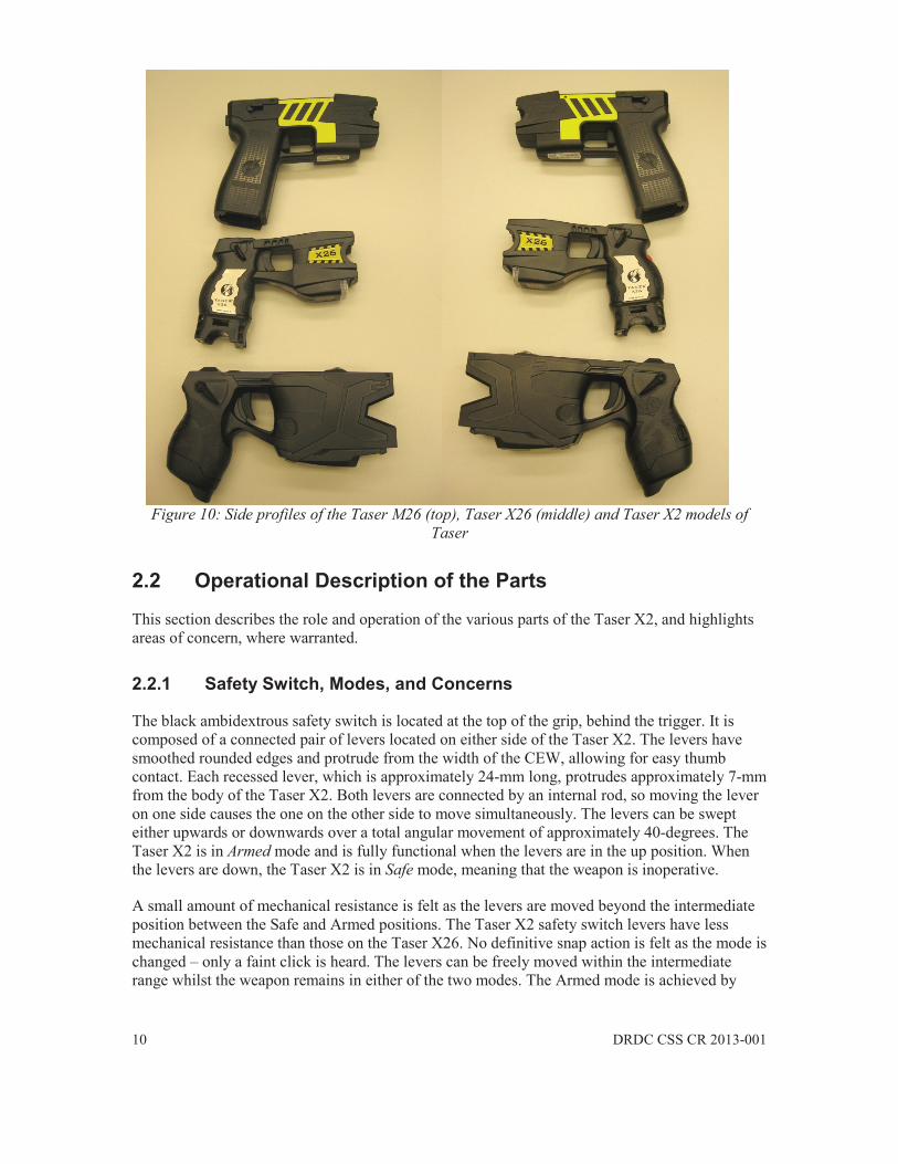
Figure 10: Side profiles of the Taser M26 (top), Taser X26 (middle) and Taser X2 models of Taser ............................................................................................................................ 10
Figure 11: Example of the Central Information Display, reproduced from [2] without permission ................................................................................................................... 14
Figure 12: Smart Cartridge Revision X1 models 22150, 22152, 22151, and 22157 (left to right) ............................................................................................................................ 16
Figure 13: Smart Cartridge probe .................................................................................................. 16
Figure 14: Smart Cartridge showing the three contact points and serial number .......................... 17
Figure 15: Three different Taser X2 PPM models viewed from the side ...................................... 17
Figure 16: Three different Taser X2 PPM models viewed from the bottom ................................. 18
Figure 17: Contact pads on the PPMs ........................................................................................... 19
Figure 18: Identification numbers and warning label on the PPM. ............................................... 20
Figure 19: Taser CAM HD promotional images, reproduced from [5] without permission ......... 21
Figure 20: USB adapter partially inserted into the Taser X2 grip ................................................. 22
Figure 21: Evidence Sync PC user interface ................................................................................. 23
Figure 22: Online Evidence Sync login screen ............................................................................. 24
Figure 23: Firmware update notification window ......................................................................... 25
Figure 24: Evidence Sync Device Summary screen ...................................................................... 25
Figure 25: Top portion of a Deployment Log showing the earliest entries for the weapon .......... 27

viii DRDC CSS CR 2013-001
Figure 26: Ambiguous Deployment Log entries ........................................................................... 27
Figure 27: Device Settings screen ................................................................................................. 28
Figure 28: Firmware History screen .............................................................................................. 29
Figure 29: Event Log screen .......................................................................................................... 30
Figure 30: Details regarding an arming event ............................................................................... 30
Figure 31: Same trigger event recorded in the Deployment Log .................................................. 31
Figure 32: Pulse Log options regarding the trigger event ............................................................. 31
Figure 33: Arc Potential Pulse Log ............................................................................................... 32
Figure 34: Measured peak arc voltage for this trigger event ......................................................... 32
Figure 35: Stimulation Potential Pulse Log ................................................................................... 33
Figure 36: Measured peak main phase voltage for this trigger event ............................................ 34
Figure 37: Charge Pulse Log ......................................................................................................... 35
Figure 38: Measured total charge for this trigger event ................................................................ 35
Figure 39: Charge Pulse Log for a missed shot ............................................................................. 36
Figure 40: Reconnection message following a firmware update ................................................... 37
Figure 41: Panel material with the fabric removed (left) and with the cardboard layer removed (right)........................................................................................................................... 38
Figure 42: Top probe embedded into the panel and its impact hole into the cardboard ................ 39
Figure 43: Bottom probe impact point with and without the cardboard layer ............................... 39
Figure 44: Irregular separation of the blast doors .......................................................................... 40
Figure 45: Images showing both sides of the deployed cartridge, where the circles indicate damage to the two top support rings of the cartridge .................................................. 41
Figure 46: Close-up of a deployed cartridge showing the lead wire attachment. Insets are of a probe and a front view of the same cartridge .............................................................. 42
Figure 47: Taser X2 cartridge separated into two part .................................................................. 43
Figure 48: Side view of the hollow cartridge part (left) and the recovered blast doors (right) ..... 43
Figure 49: Close-up of the top-front of the Taser X2, where the cartridge L-shaped tab meets the Taser X2 arc point. The inset is a side view of a cartridge partially inserted into the Taser X2 ......................................................................................................... 44
Figure 50: Simulated ejection sequence of hollow cartridge part ................................................. 45
Figure 51: Conceptual diagram of the electrical test apparatus ..................................................... 46
Figure 52: Photograph of the test bench apparatus ........................................................................ 46
Figure 53: (a) Insulated wires inserted into a spent cartridge with its hollow part removed, and (b) close-up of bare wire emerging from one of the drilled holes ............................... 47
DRDC CSS CR 2013-001 ix
Figure 54: (a) Test cartridge with hollow part re-attached, with bare wires emerging from the front, and (b) close-up of one of the bare wires emerging very near to the conductive L-shaped pad without touching it. ............................................................ 48
Figure 55: (a) Test cartridge inserted into the right-side bay of the Taser X2, and (b) close-up showing the small gap that is maintained between the bare test lead wire and the tab of the cartridge ...................................................................................................... 48
Figure 56: Typical measured Taser X2 voltage pulse ................................................................... 51
Figure 57: Typical calculated Taser X2 current pulse ................................................................... 52
Figure 58: Overlay of all 98 pulses contained in a 5-second discharge from the right-side bay ... 53
Figure 59: Arc phase peak voltage of all 98 pulses contained in a 5-second discharge cycle from the right-side bay ................................................................................................ 54
Figure 60: Main phase peak voltage of all 98 pulses contained in a 5-second discharge cycle from the right-side bay ................................................................................................ 55
Figure 61: Total charge from each of the 98 pulses contained in a 5-second discharge cycle from the right-side bay ................................................................................................ 56
Figure 62: Pulse repetition interval of all 97 inter-pulse periods contained in a 5-second discharge cycle from the right-side bay ...................................................................... 57
Figure 63: Pulse length of all 98 pulses contained in a 5-second discharge cycle from the right-side bay ............................................................................................................... 58
Figure 64: Overlay of all 98 pulses contained in a 5-second discharge cycle from the left-side bay ............................................................................................................................... 59
Figure 65: Arc phase peak voltage of all 98 pulses contained in a 5-second discharge cycle from the left-side bay .................................................................................................. 60
Figure 66: Main phase peak voltage of all 98 pulses contained in a 5-second discharge cycle from the left-side bay .................................................................................................. 61
Figure 67: Total charge from each of the 98 pulses contained in a 5-second discharge cycle from the left-side bay .................................................................................................. 62
Figure 68: Pulse length of all 98 pulses contained in a 5-second discharge cycle from the left-side bay........................................................................................................................ 63

x DRDC CSS CR 2013-001
List of tables
Table 1: Taser X2 Trigger Action ................................................................................................. 12
Table 2: Smart Cartridge Models .................................................................................................. 15
Table 3: Mean values of the measured parameters for right-side bay trigger pull ........................ 53
Table 4: Mean values of the measured parameters for left-side bay trigger pull .......................... 59
Table 5: Mean values of the measured parameters for different trigger pulls ............................... 64

DRDC CSS CR 2013-001 xi
Acknowledgements
The author would like to thank Dr. Yahia Antar, Royal Military College of Canada, for the introduction to the CEW strategic initiative. The author would also like to thank Mr. David Lee, Communications Research Centre Canada, and Mr. Symon Podilchak, Royal Military College of Canada, for their assistance and helpful discussions at the beginning of this project.

DRDC CSS CR 2013-001 1
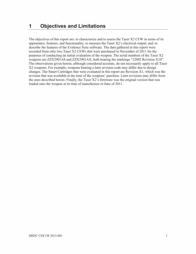
1 Objectives and Limitations
The objectives of this report are: to characterize and to assess the Taser X2 CEW in terms of its appearance, features, and functionality; to measure the Taser X2’s electrical output; and, to describe the features of the Evidence Sync software. The data gathered in this report were recorded from only two Taser X2 CEWs that were purchased in November of 2011 for the purposes of conducting an initial evaluation of the weapon. The serial numbers of the Taser X2 weapons are ZZX2901A8 and ZZX2901AX, both bearing the markings “22002 Revision X10”. The observations given herein, although considered accurate, do not necessarily apply to all Taser X2 weapons. For example, weapons bearing a later revision code may differ due to design changes. The Smart Cartridges that were evaluated in this report are Revision X1, which was the revision that was available at the time of the weapons’ purchase. Later revisions may differ from the ones described herein. Finally, the Taser X2’s firmware was the original version that was loaded onto the weapon at its time of manufacture in June of 2011.
2 DRDC CSS CR 2013-001
2 Physical Properties of the Taser X2
2.1 General Physical Description
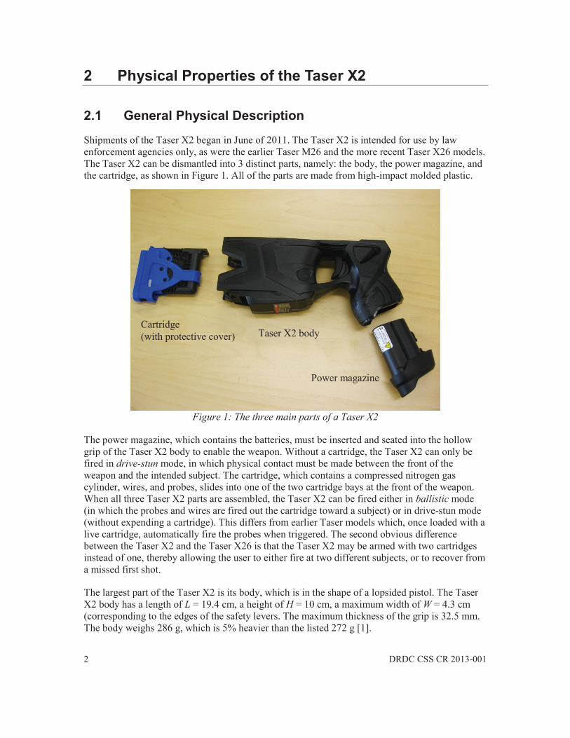
Shipments of the Taser X2 began in June of 2011. The Taser X2 is intended for use by law enforcement agencies only, as were the earlier Taser M26 and the more recent Taser X26 models. The Taser X2 can be dismantled into 3 distinct parts, namely: the body, the power magazine, and the cartridge, as shown in Figure 1. All of the parts are made from high-impact molded plastic.
Figure 1: The three main parts of a Taser X2
The power magazine, which contains the batteries, must be inserted and seated into the hollow grip of the Taser X2 body to enable the weapon. Without a cartridge, the Taser X2 can only be fired in drive-stun mode, in which physical contact must be made between the front of the weapon and the intended subject. The cartridge, which contains a compressed nitrogen gas cylinder, wires, and probes, slides into one of the two cartridge bays at the front of the weapon. When all three Taser X2 parts are assembled, the Taser X2 can be fired either in ballistic mode (in which the probes and wires are fired out the cartridge toward a subject) or in drive-stun mode (without expending a cartridge). This differs from earlier Taser models which, once loaded with a live cartridge, automatically fire the probes when triggered. The second obvious difference between the Taser X2 and the Taser X26 is that the Taser X2 may be armed with two cartridges instead of one, thereby allowing the user to either fire at two different subjects, or to recover from a missed first shot.
The largest part of the Taser X2 is its body, which is in the shape of a lopsided pistol. The Taser X2 body has a length of L = 19.4 cm, a height of H = 10 cm, a maximum width of W = 4.3 cm (corresponding to the edges of the safety levers. The maximum thickness of the grip is 32.5 mm. The body weighs 286 g, which is 5% heavier than the listed 272 g [1].
Cartridge (with protective cover) Taser X2 body
Power magazine

DRDC CSS CR 2013-001 3
Adding a power magazine extends both the length and the height of the weapon slightly because the bottom of the power magazine protrudes from the bottom of the grip. With a standard model 22010 power magazine inserted, the dimensions of the weapon are L = 19.8 cm, H = 10.7 cm, and W = 4.3 cm [1]. When present, the cartridges seat fully within the front slots (cartridge bays) of the weapon and do not alter the weapon’s dimensions. With a standard power magazine and two cartridges inserted, the Taser X2 weighs approximately 454 g (1 lb) [1].
Descriptors such as left, right, top and bottom are relative to the viewpoint of the user of the Taser X2 who is gripping the weapon in the normal fashion, with arms extended toward a target. Figure 2 and Figure 3 are photographs of the right and left sides, respectively, of the Taser X2 with a power magazine inserted but without a cartridge.
Figure 2: Taser X2 viewed from the right side, without cartridges
Trigger
Power magazine (inserted)
Grip
Safety switch Right arc button
Warning label
Serial numbers
LED flashlight and lasers
Cartridge bays

4 DRDC CSS CR 2013-001
Figure 3: Taser X2 viewed from the left side, without cartridges
Although the Taser X2 is pistol-shaped, the front part of the weapon is larger and wider than the grip. The grip has an elliptical cross-section that is embossed with a texturized Taser International logo (a stylized lightning bolt) on both sides. The left and right sides of the Taser X2 are almost identical except for the direction of the Taser International logo on the grip, the location of the embossed stylized “2” on the body, and the placement of the power magazine release button on the rear-left side of the grip. When inserted, the power magazine forms the lower part of the grip. Two rubberized, stylized, momentary-on arc buttons are located on either side of the Taser X2 in front of the trigger. The locations of the serial numbers, warning label, cartridge release button, LED flashlight, and lasers are also indicated along the bottom of the Taser X2 in Figure 2 and Figure 3. When viewed from the side, the cartridges bays and the arc points are obscured by black plastic fins that extend along the front sides of the Taser X2.
The top of the Taser X2 is shown in Figure 4, which clearly reveals the larger width of the front of the weapon. The maximum width, however, is at the location of the safety switch. The Central Information Display bezel, located at the top of the grip and facing toward the rear of the Taser X2, is also visible in Figure 4.
Power magazine release button
Left arc button Left side of safety switch
Cartridge release button

DRDC CSS CR 2013-001 5
Figure 4: Taser X2 viewed from the top, without cartridges
The double levers of the safety switch protrude beyond the width of the Taser X2 body. The mechanical sights of the Taser X2, consisting of two offset rear blades and a single central front blade, are located along the barrel axis of the Taser X2. The recessed Illumination Selector button is positioned in front of the rear sight blades. Figure 5 shows two photographs of the Taser X2 viewed from the bottom, with and without its power magazine.
(a) (b)
Figure 5: Taser X2 viewed from bottom (a) with power magazine removed and (b) with a power magazine inserted, with insets of the warning label, barcode, and serial numbers.
Rear sight blades
Central Information Display
Illumination Selector button
Front sight blade Right safety switch
Cartridge bays and arc points
Power magazine (removed)
Cavity in grip for power magazine
Internal contact points
2D Barcode and serial number
Warning label

6 DRDC CSS CR 2013-001
Figure 5a reveals the hollow grip into which the power magazine is inserted. The electrical contact points that connect to the power magazine are discernible in the grip cavity shown in Figure 5a. The warning label shown in Figure 5b is self-evident. The 2D barcode, barcode number, serial number (ZZX2901A8) and revision number (22002 Rev X10) are printed on the bottom side of the Taser X2 body in front of the trigger. The yellow sticker on the base of the power magazine will be explained in a subsequent section, as it is particular to a specific type of power magazine. Figure 6 illustrates the rear and front views of the Taser X2.
(a) (b)
Figure 6: Taser X2 viewed from (a) the rear, and (b) from the front, without cartridges
In Figure 6a, the power magazine release button is evident on the left-side of the grip. The two levers of the safety switch are plainly visible on either side of the top of the grip, as is the Central Information Display window. The rear sight blades are located at the top.
Figure 6b shows the front view of the Taser X2. The two bays that accommodate the cartridges are evident here. Low-voltage contact points at the back of each cartridge bay cavity (not visible) provide electrical signal connections between the Taser X2 and the cartridge. Below the cartridge bays is a window, behind which are located the central LED flashlight and the two laser sights. One laser estimates the aim of the top probe while the other estimates the aim of the bottom probe (calibrated at a 15-foot range) [2]. Four metallic arc points, which sustain the high voltage electrical arcs at the front of the weapon, are recessed in the bays. Note how the upper two arc points are offset with respect to the lower two. When used in drive-stun mode without cartridges, arcs are established diagonally across each bay. The arc points on the Taser X2 body do not initiate probe deployment, as is the case with the Taser X26. Rather, each cartridge has additional contact points that connect to the Taser X2 body, and these are used to trigger probe deployment.
Central Information Display
Left safety switch
Rear sight blades
Power magazine
Power magazine release button
LED flashlight
Laser sights
Left bay arc points
Cartridge bay cavities
Right bay arc points
DRDC CSS CR 2013-001 7
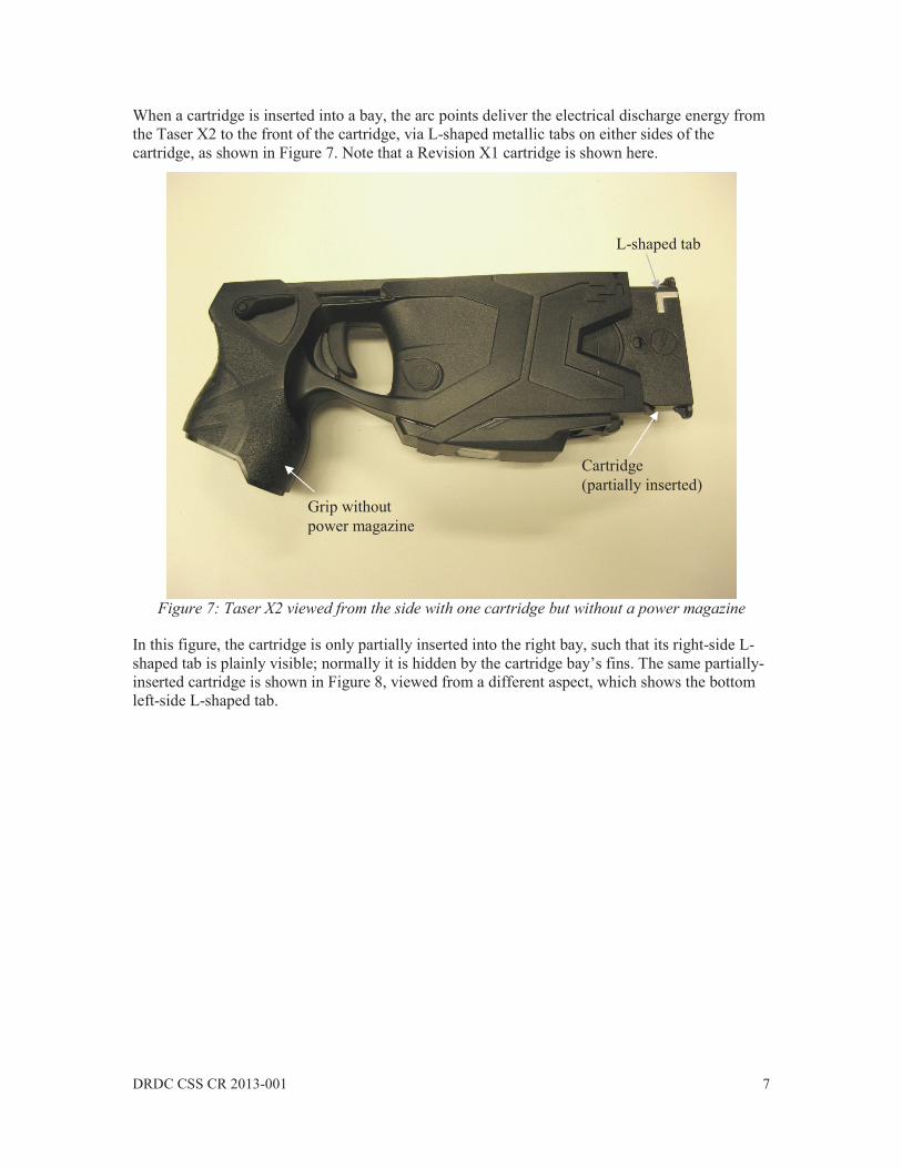
When a cartridge is inserted into a bay, the arc points deliver the electrical discharge energy from the Taser X2 to the front of the cartridge, via L-shaped metallic tabs on either sides of the cartridge, as shown in Figure 7. Note that a Revision X1 cartridge is shown here.
Figure 7: Taser X2 viewed from the side with one cartridge but without a power magazine
In this figure, the cartridge is only partially inserted into the right bay, such that its right-side L-shaped tab is plainly visible; normally it is hidden by the cartridge bay’s fins. The same partially-inserted cartridge is shown in Figure 8, viewed from a different aspect, which shows the bottom left-side L-shaped tab.
Cartridge (partially inserted)
L-shaped tab
Grip without power magazine
8 DRDC CSS CR 2013-001
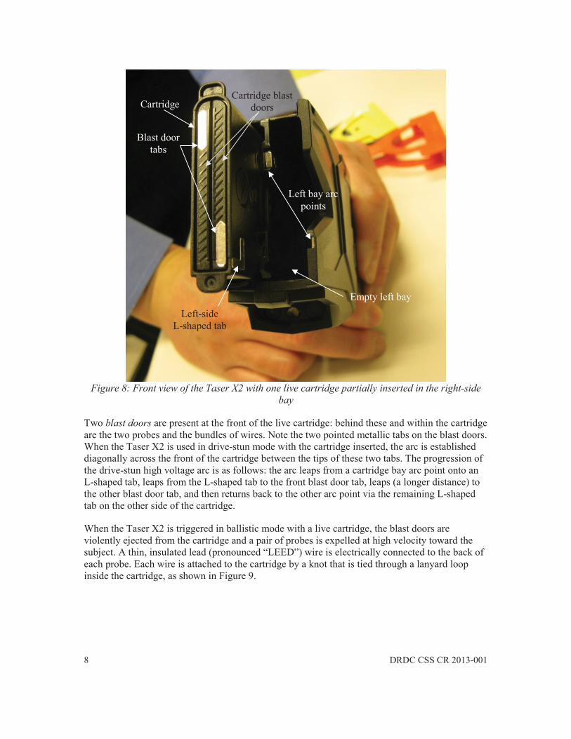
Figure 8: Front view of the Taser X2 with one live cartridge partially inserted in the right-side bay
Two blast doors are present at the front of the live cartridge: behind these and within the cartridge are the two probes and the bundles of wires. Note the two pointed metallic tabs on the blast doors. When the Taser X2 is used in drive-stun mode with the cartridge inserted, the arc is established diagonally across the front of the cartridge between the tips of these two tabs. The progression of the drive-stun high voltage arc is as follows: the arc leaps from a cartridge bay arc point onto an L-shaped tab, leaps from the L-shaped tab to the front blast door tab, leaps (a longer distance) to the other blast door tab, and then returns back to the other arc point via the remaining L-shaped tab on the other side of the cartridge.
When the Taser X2 is triggered in ballistic mode with a live cartridge, the blast doors are violently ejected from the cartridge and a pair of probes is expelled at high velocity toward the subject. A thin, insulated lead (pronounced “LEED”) wire is electrically connected to the back of each probe. Each wire is attached to the cartridge by a knot that is tied through a lanyard loop inside the cartridge, as shown in Figure 9.
Cartridge
Blast door tabs
Left-side L-shaped tab
Left bay arc points
Cartridge blast doors
Empty left bay
DRDC CSS CR 2013-001 9
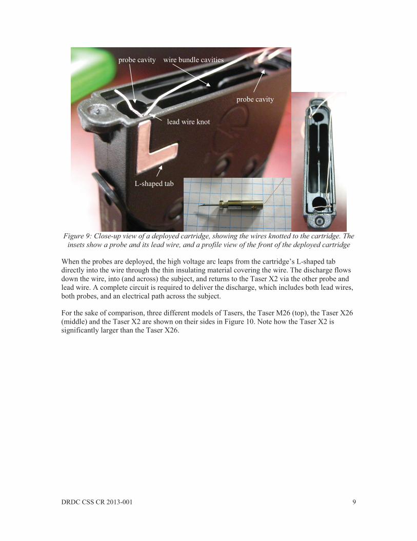
Figure 9: Close-up view of a deployed cartridge, showing the wires knotted to the cartridge. The insets show a probe and its lead wire, and a profile view of the front of the deployed cartridge
When the probes are deployed, the high voltage arc leaps from the cartridge’s L-shaped tab directly into the wire through the thin insulating material covering the wire. The discharge flows down the wire, into (and across) the subject, and returns to the Taser X2 via the other probe and lead wire. A complete circuit is required to deliver the discharge, which includes both lead wires, both probes, and an electrical path across the subject.
For the sake of comparison, three different models of Tasers, the Taser M26 (top), the Taser X26 (middle) and the Taser X2 are shown on their sides in Figure 10. Note how the Taser X2 is significantly larger than the Taser X26.
L-shaped tab
lead wire knot
probe cavity wire bundle cavities
probe cavity
10 DRDC CSS CR 2013-001
Figure 10: Side profiles of the Taser M26 (top), Taser X26 (middle) and Taser X2 models of Taser
2.2 Operational Description of the Parts
This section describes the role and operation of the various parts of the Taser X2, and highlights areas of concern, where warranted.
2.2.1 Safety Switch, Modes, and Concerns
The black ambidextrous safety switch is located at the top of the grip, behind the trigger. It is composed of a connected pair of levers located on either side of the Taser X2. The levers have smoothed rounded edges and protrude from the width of the CEW, allowing for easy thumb contact. Each recessed lever, which is approximately 24-mm long, protrudes approximately 7-mm from the body of the Taser X2. Both levers are connected by an internal rod, so moving the lever on one side causes the one on the other side to move simultaneously. The levers can be swept either upwards or downwards over a total angular movement of approximately 40-degrees. The Taser X2 is in Armed mode and is fully functional when the levers are in the up position. When the levers are down, the Taser X2 is in Safe mode, meaning that the weapon is inoperative.
A small amount of mechanical resistance is felt as the levers are moved beyond the intermediate position between the Safe and Armed positions. The Taser X2 safety switch levers have less mechanical resistance than those on the Taser X26. No definitive snap action is felt as the mode is changed – only a faint click is heard. The levers can be freely moved within the intermediate range whilst the weapon remains in either of the two modes. The Armed mode is achieved by

DRDC CSS CR 2013-001 11
moving the lever up by approximately 40% of the total lever’s travel; hence the Armed mode occupies more of the lever’s travel range. It should be noted that the Taser M26 safety switch had a clear snapping action that is lacking on the Taser X26 and Taser X2. The lack of a snapping action on the safety switch is a concern, as the levers could be accidently moved if an object is inadvertently brushed-up against the side of the weapon. If the LED flashlight and sighting lasers are turned off, only the dimmed illumination of the rear Central Information Display (see Section 2.2.4) indicates that the Taser X2 is armed. Given that the levers may travel significantly in the intermediate positions, it may be possible to incorrectly assess the mode of the Taser X2 based on a quick visual inspection of the levers alone.
2.2.2 Left and Right Arc Buttons
Two rubberized, recessed, 11-mm diameter momentary-on buttons, called arc buttons, are located on either side of the weapon, in front of the trigger. The buttons can be readily depressed by extending an index finger beyond the trigger whilst gripping the weapon. Each button has a slightly raised plastic edge that encircles the button toward the front of the weapon (the edge spans approximately 60 of the circumference of the button). A significant pressure is required to depress an arc button and therefore it seems unlikely that it could be inadvertently depressed.
The arc buttons serve three purposes: (1) they can be used to create a momentary high voltage discharge, (2) they can be used to select the next bay to be triggered (cartridge advance), or (3) they can be used as menu scrolling and selection buttons.
2.2.2.1 Arc Buttons for Momentary High Voltage Discharges
When the Taser X2 is armed, pressing and holding down either arc button will create high voltage discharges simultaneously in both bays of the Taser X2 until the arc button is released. With no cartridges inserted, this is the recommended way to perform a spark test [2], although it can also be used to display a warning arc, or to momentarily provide a drive-stun discharge. If live cartridges are present inside the bays, arcs are formed across the front of the blast doors – the cartridges will not deploy by using the arc buttons alone. If cartridges with deployed wires are present inside the bays, the arc buttons will re-energize the deployed wires, which will deliver a discharge down the wires. It is important to remember that the arc buttons will not fire probes, but they will cause high voltage discharges into both bays regardless of what is connected to them (empty, live cartridge, deployed cartridge), and only while the arc button is depressed.
2.2.2.2 Arc Buttons for Cartridge Advance
If only one cartridge is loaded into the Taser X2, the weapon will automatically select and lock to that bay when armed, meaning that that cartridge alone will fire when the trigger is pulled.
The bay that will fire upon the next trigger pull is indicated on the Central Information Display (see Section 2.2.4 and [2]). When two live cartridges are loaded, the Taser X2 will default to the left cartridge bay when it is armed. However, by momentarily depressing either arc button, the right bay can be selected instead. Subsequent short pushes of the arc button alternate between selecting the left and the right bay. This is useful for selecting between two different cartridge types that may be present in the two bays.
12 DRDC CSS CR 2013-001
In its default setting, after firing a cartridge, the Taser X2 automatically advances to the next available cartridge, which is known as the semi-automatic operating mode [2]. The semi-automatic icon (two triangles) is indicated in Figure 11. In firmware version 3.033, the latest at the time of this writing, the option to disable the semi-automatic mode also exists, which places the cartridge advance function into manual mode [4]. In manual cartridge advance mode, the user must depress an arc button to select the next bay. This option is shown later in Section 3.2.
2.2.2.3 Arc Buttons as Menu Buttons
When the Taser X2 is in Safe mode, when the Illumination Selector switch is subsequently depressed, in conjunction with the Central Information Display (see Section 2.2.4), momentarily depressing the arc buttons serves either to scroll down a menu list (right arc button), or to select a menu item (left arc button). In this context, the left arc button is not the same as the right arc button (LEFT is select, RIGHT is scroll).
2.2.3 Trigger
The trigger is positioned in the usual firearm location, in front of the grip. Depressing the trigger causes a momentary-on button to be depressed within the Taser X2 for the duration of the trigger pull. Only a slight clicking sensation is felt, and a faint click is heard, when the trigger is pulled. Releasing the trigger causes the internal button to turn off and causes the trigger to return to its normal position. A thin plastic wedge limits the travel of the trigger and prevents items from being jammed behind the trigger. The trigger’s finger-hole aperture is approximately 20-mm in length (along the weapon’s axis), and 30-mm in height.
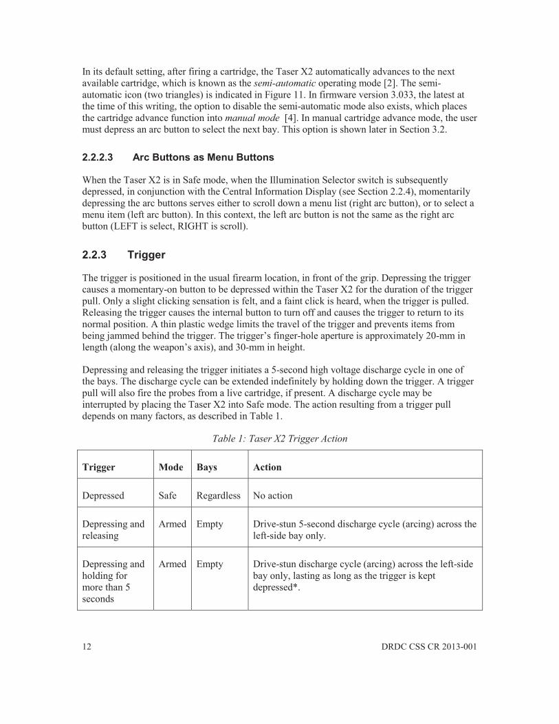
Depressing and releasing the trigger initiates a 5-second high voltage discharge cycle in one of the bays. The discharge cycle can be extended indefinitely by holding down the trigger. A trigger pull will also fire the probes from a live cartridge, if present. A discharge cycle may be interrupted by placing the Taser X2 into Safe mode. The action resulting from a trigger pull depends on many factors, as described in Table 1.
Table 1: Taser X2 Trigger Action
Trigger Mode Bays Action
Depressed Safe Regardless No action
Depressing and releasing
Armed Empty Drive-stun 5-second discharge cycle (arcing) across the left-side bay only.
Depressing and holding for more than 5 seconds
Armed Empty Drive-stun discharge cycle (arcing) across the left-side bay only, lasting as long as the trigger is kept depressed*.

DRDC CSS CR 2013-001 13
Depressing and releasing
Armed 2 live cartridges
Probes are fired from the underlined cartridge displayed on the CID, followed by a 5-second discharge cycle into the deployed cartridge. Holding the trigger down for longer than 5 seconds continues the discharge cycle until the trigger is released*.
Depressing and releasing and depressing again
Armed 2 live cartridges
Probes are fired from one cartridge upon the first trigger pull, and a 5-second discharge cycle is initiated. The second trigger fires the other cartridge regardless of whether the first 5-second cycle is complete, and initiates a 5-second discharge cycle into the 2nd deployed cartridge. The discharge cycles are independent of one another, each having its own countdown. Longer discharges are obtained by holding the trigger down (beyond 5 seconds)*
Subsequent trigger pulls after firing both cartridges
Armed Deployed A 5-second discharge is initiated into the bay indicated by the CID, which alternates between the bays for subsequent trigger pulls. A discharge cycle can be initiated in the next bay regardless of whether or not it has completed in the other bay – the discharge cycles are independent of one another, each having its own countdown. Longer discharges are obtained by holding the trigger down (beyond 5 seconds)*
* unless an APPM power magazine is inserted (see Section 2.2.7)
Given the large number of permutations listed in Table 1 regarding the order of cartridge firing, the trigger action, and the arc buttons, there exists the possibility of confusion on the part of a user placed in a high stress situation regarding how the weapon should be fired. Training specific to the Taser X2 is therefore highly recommended.
2.2.4 Central Information Display (CID) and Illumination Selector
The CID is an LED display located at the top-rear of the Taser X2, facing the user. The CID is only illuminated when the Taser X2 is placed in Armed mode, or if the Illumination Selector is depressed while in Safe mode. In Armed mode, the CID displays the firing status of the Taser X2, including: remaining battery power, cartridge types in both bays, cartridge status, the next bay to fire, the duration of a trigger pull, and if any errors have occurred [2].

14 DRDC CSS CR 2013-001
Figure 11: Example of the Central Information Display, reproduced from [2] without permission
Recall that the Illumination Selector switch is located on the top of the Taser X2, in front of the rear sights. Pressing the Illumination Selector while the Taser X2 is armed turns off the LED flashlight and lasers, and dims the CID (stealth mode). Pressing it again returns the weapon to its default illumination. If the Illumination Selector is depressed while the Taser X2 is in safe mode, the CID displays a number of menu options that can be selected using the arc buttons. The main menu items are: Sighting, Info, and Options. The menu mode times-out after one minute if no input is registered from the user. The menu items listed below were specific to firmware version 2.00 – they should be verified against the latest firmware update.
Choosing the Options menu item allows the user to turn the Power Save feature on or off [2]. When Power Save is enabled, the Taser X2 will automatically power-down after being armed for 20 minutes. To re-arm the Taser X2 after a power-down, the Safety Switch must be returned to the Safe position before placing it in Armed mode again.
By selecting the Sighting menu item, the user can specify whether or not the LED flashlight and/or lasers will illuminate when the Taser X2 is placed in Armed mode.
Selecting the Info menu item leads to another menu that contains items labelled System, PPM, and Eng Code. System lists the Taser X2 serial number, the date, the time, and the firmware version. PPM displays the power magazine’s serial number, the measured battery voltage, and the percentage of battery power remaining. Eng Code displays 3 rows of 8 digits (normally all zeros).
It should be noted that depressing the small, rigid, recessed Illumination Selector switch on the top of the Taser X2 is difficult and awkward with a finger, (a finger nail must be used) and it is likely that some small, pointed object would be used in practice, even though Taser International recommends against doing so [2].
2.2.5 Laser Sights and Flashlight
Whereas the older Taser X26 model was equipped with only one laser sight, the Taser X2 has two. Only one of the lasers illuminates (the one on the left of weapon) when the Taser X2 cartridge bays are empty. When a cartridge is present in the bays, both lasers illuminate. This laser on the left of the weapon is aimed straight ahead to the estimate the impact site of the top probe at a 15-foot range (for the 25-foot cartridge only). The laser on the right of the weapon, which blinks, points downward at an 8-degree angle (approximately 1-foot for every 7-feet of distance from the target [2]) to estimate the impact site of the bottom probe, calibrated at a 15-foot range (for the 25-foot cartridge only). The lasers are not indicative of the probe impact sites for 35-foot cartridges.

DRDC CSS CR 2013-001 15
The flashlight LED is located between the two lasers at the front of the weapon. The lasers and the flashlight illuminate when the Taser X2 is placed in armed mode. They can be disabled by accessing the Sighting menu as described in Section 2.2.4. While armed, the flashlight and lasers can also be turned off by entering the so-called stealth mode by depressing the Illumination Selector button.
2.2.6 Cartridges
Without cartridges, the Taser X2 can only be used to display arcs or to deliver an electrical stimulus into a subject using the drive-stun mode, in which physical contact between the weapon and the subject is required. When a cartridge is inserted into the front bay of the Taser X2, the drive-stun mode can still be used by depressing and holding one of the arc buttons. With a cartridge inserted, depressing the trigger causes two probes to be ejected from the cartridge, which then deliver the electrical stimulus to the subject via thin insulated wires that connect the back of the probes to the cartridge. Small, round, confetti-like paper identifiers, which list the serial number of the cartridge, are also ejected along with the probes. These are known as Anti-Felon Identification Tags, or AFIDs, and are intended to identify the locations where a cartridge has been fired for forensic purposes. The cartridges used by the Taser X2, called Smart Cartridges, are also compatible with the Taser X3 model but not with the earlier Taser X26 and Taser M26 models. The Taser X2 can accommodate up to two cartridges whereas the Taser X3 can accommodate up to three. Five Smart Cartridge models are currently available, as listed in Table 2.
Table 2: Smart Cartridge Models
Cartridge Model Description
22150 15-foot wires, yellow protector with yellow blast doors
22151 25-foot wires, green protector with black blast doors
22152 35-foot wires, orange protector with black blast doors
22155 25-foot inert, blue protector with clear blast doors (training)
22157 25-foot non-conductive wires, blue protector with blue blast doors (training)
The 25-foot model is the recommended cartridge for field use, as the laser sights are calibrated for this cartridge at a 15-foot range [2]. The 35-foot model is intended for tactical field use, whereas the 15-foot model is intended for live training. Model 22155 is inert and is intended for demonstration purposes, whereas model 22157 contains non-conductive wires and is intended for firing training purposes. Four of the five models are shown in Figure 12.

16 DRDC CSS CR 2013-001
Figure 12: Smart Cartridge Revision X1 models 22150, 22152, 22151, and 22157 (left to right)
Note that these are early models of the Smart Cartridge (Revision X1) – newer revisions likely exist. The maximum dimensions of a cartridge are 7 cm 6.4 cm 1.27 cm and a cartridge can weigh between 41 and 45 g depending on the length of wire contained within it. One of the two probes that are fired by the 22150, 22151 and 22152 cartridges is shown in Figure 13.
Figure 13: Smart Cartridge probe
The needle-like barb is approximately 13-mm long, which corresponds to the length of a so-called Extra-Penetration (XP) probe. The training cartridge contains shorter barbs (approximately 9- mm long). Unlike the earlier Taser X26 cartridges, drive-stun arcs can be supported across the front blast doors of the Smart Cartridges. The high-voltage arcs produced by the Taser X2 do not trigger the cartridge; instead, the Taser X2 trigger signal is sent to the Smart Cartridge via a separate electrical connection that is made between the Taser X2 and the cartridge at the back of the each cartridge bay. Figure 14 shows the three 7.5-mm long gold plated contact points on a cartridge that connect to the Taser X2.
DRDC CSS CR 2013-001 17
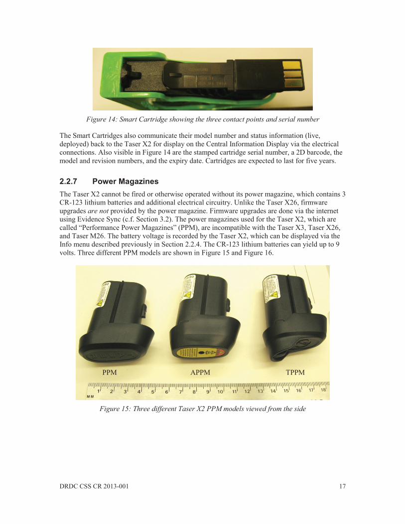
Figure 14: Smart Cartridge showing the three contact points and serial number
The Smart Cartridges also communicate their model number and status information (live, deployed) back to the Taser X2 for display on the Central Information Display via the electrical connections. Also visible in Figure 14 are the stamped cartridge serial number, a 2D barcode, the model and revision numbers, and the expiry date. Cartridges are expected to last for five years.
2.2.7 Power Magazines The Taser X2 cannot be fired or otherwise operated without its power magazine, which contains 3 CR-123 lithium batteries and additional electrical circuitry. Unlike the Taser X26, firmware upgrades are not provided by the power magazine. Firmware upgrades are done via the internet using Evidence Sync (c.f. Section 3.2). The power magazines used for the Taser X2, which are called “Performance Power Magazines” (PPM), are incompatible with the Taser X3, Taser X26, and Taser M26. The battery voltage is recorded by the Taser X2, which can be displayed via the Info menu described previously in Section 2.2.4. The CR-123 lithium batteries can yield up to 9 volts. Three different PPM models are shown in Figure 15 and Figure 16.
Figure 15: Three different Taser X2 PPM models viewed from the side
PPM APPM TPPM

18 DRDC CSS CR 2013-001
Figure 16: Three different Taser X2 PPM models viewed from the bottom
The bulk of the black molded-plastic power magazine has an elliptical cross-section, which slides and locks into the hollow grip of the Taser X2. The base of the magazine protrudes from the bottom of grip, and depending on the power magazine option, this protrusion may be significant enough to extend the bottom part of the grip. The top of the magazine contains a recessed rectangular area containing rectangular, gold-plated contact pads that make electrical contact with the circuitry contained within the body of the Taser X2. The rounded sides of the power magazine are keyed such that the magazine must be properly oriented before it can be inserted into the grip. A significant force is required to fully seat the magazine into the grip, which engages a spring-loaded locking tab inside the grip that secures the magazine to the body. The power magazine release button, located on the grip of the Taser X2, rises flush with the grip surface only when the magazine is fully seated and locked. The locking tab interacts with notches in the keyed part of the magazine. To remove a locked magazine, the power magazine release button must be depressed whilst simultaneously pulling out the magazine. An intermediate notch in the magazine allows the locking tab to hold (but not lock) the magazine such that it does not fall out – a pulling force is therefore required to remove the power magazine. Model 22010 is the standard PPM and weighs 69 g. It is claimed that this PPM can generate approximately 500 discharge cycles, depending on the temperature and flashlight use [2]. Part number 22012, the “Tactical Performance Power Magazine” (TPPM), which weighs 70.6 g, differs by its curved plastic wall that protrudes by 12.5-mm from the rear bottom surface of the base of the magazine. This wall shrouds a loop that can accommodate a lanyard. Model 22011, the “Automatic Shut-Down Performance Power Magazine” (APPM), weighs 71.3 g and has a longer, bevelled base that protrudes more from the bottom of the CEW grip. The flat, visible, bottom surface of the APPM base has a yellow sticker that surrounds a small circular aperture that houses an internal beeper. The APPM limits trigger pull discharges to a 5-second
PPM APPM TPPM

DRDC CSS CR 2013-001 19
maximum, even if the trigger remains pulled. When the Taser X2 is 4-seconds into the cycle, the APPM will beep, alerting the user of the impending shut-down. After the APPM terminates the discharge cycle, the cartridge in the next bay (if present) will be selected. If the user wishes to re-energize the deployed cartridge, the arc buttons must be used instead. The APPM does not alter the function of the arc buttons. The recessed rectangular area on the top surface of the Taser X2’s magazines contains 16 gold-plated contact pads arranged in two rows. Each pad is approximately 2-mm by 4-mm. These pads connect the PPM to the body of the Taser X2. The pad arrangement is the same on the PPM, APPM and TPPM, as shown in Figure 17.
Figure 17: Contact pads on the PPMs
A model number, revision number, serial number and a 2D barcode are stamped on the side of each PPM, and a warning label is affixed to the rounded edge of each PPM, as shown in Figure 18.
PPM APPM TPPM
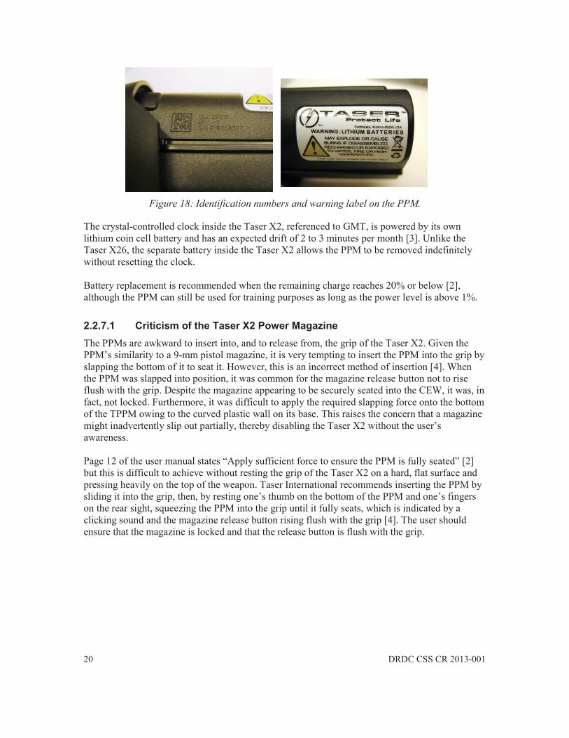
20 DRDC CSS CR 2013-001
Figure 18: Identification numbers and warning label on the PPM.
The crystal-controlled clock inside the Taser X2, referenced to GMT, is powered by its own lithium coin cell battery and has an expected drift of 2 to 3 minutes per month [3]. Unlike the Taser X26, the separate battery inside the Taser X2 allows the PPM to be removed indefinitely without resetting the clock. Battery replacement is recommended when the remaining charge reaches 20% or below [2], although the PPM can still be used for training purposes as long as the power level is above 1%.
2.2.7.1 Criticism of the Taser X2 Power Magazine The PPMs are awkward to insert into, and to release from, the grip of the Taser X2. Given the PPM’s similarity to a 9-mm pistol magazine, it is very tempting to insert the PPM into the grip by slapping the bottom of it to seat it. However, this is an incorrect method of insertion [4]. When the PPM was slapped into position, it was common for the magazine release button not to rise flush with the grip. Despite the magazine appearing to be securely seated into the CEW, it was, in fact, not locked. Furthermore, it was difficult to apply the required slapping force onto the bottom of the TPPM owing to the curved plastic wall on its base. This raises the concern that a magazine might inadvertently slip out partially, thereby disabling the Taser X2 without the user’s awareness. Page 12 of the user manual states “Apply sufficient force to ensure the PPM is fully seated” [2] but this is difficult to achieve without resting the grip of the Taser X2 on a hard, flat surface and pressing heavily on the top of the weapon. Taser International recommends inserting the PPM by sliding it into the grip, then, by resting one’s thumb on the bottom of the PPM and one’s fingers on the rear sight, squeezing the PPM into the grip until it fully seats, which is indicated by a clicking sound and the magazine release button rising flush with the grip [4]. The user should ensure that the magazine is locked and that the release button is flush with the grip.
DRDC CSS CR 2013-001 21
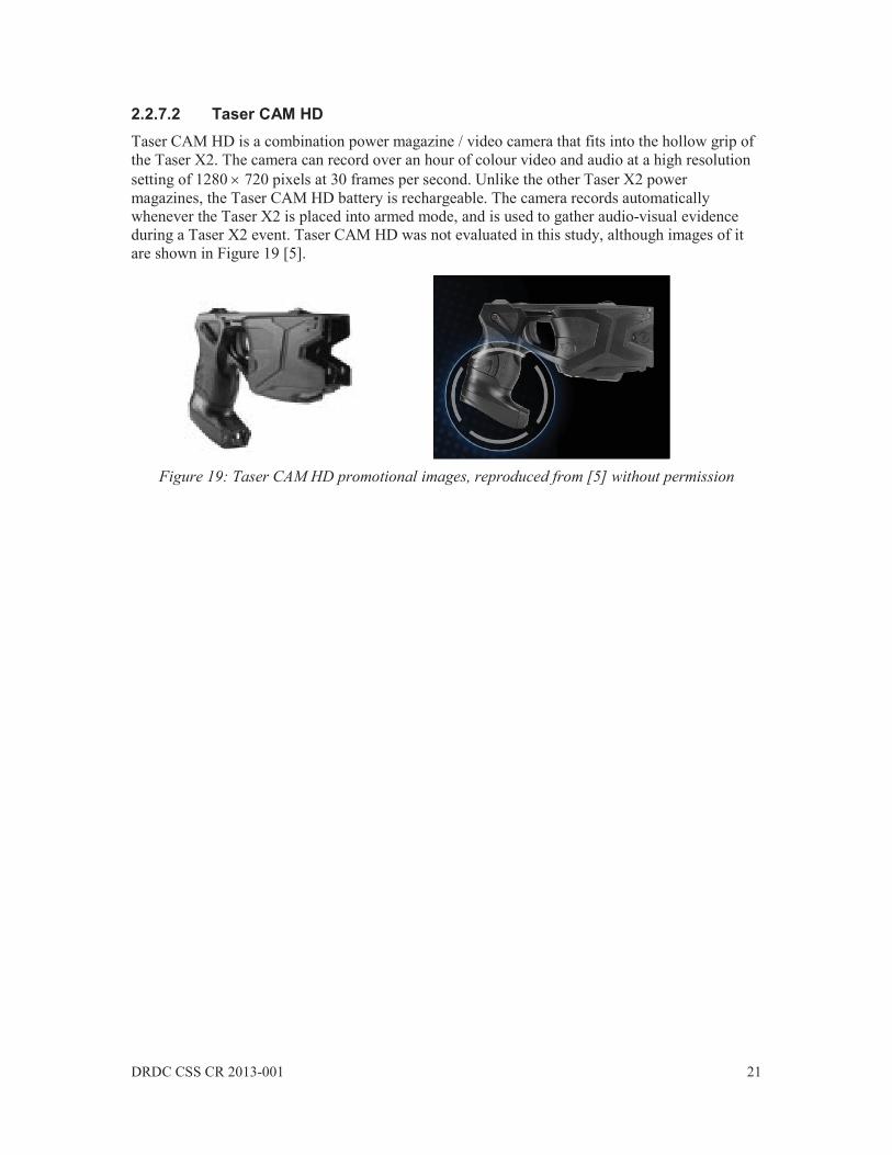
2.2.7.2 Taser CAM HD Taser CAM HD is a combination power magazine / video camera that fits into the hollow grip of the Taser X2. The camera can record over an hour of colour video and audio at a high resolution setting of 1280 720 pixels at 30 frames per second. Unlike the other Taser X2 power magazines, the Taser CAM HD battery is rechargeable. The camera records automatically whenever the Taser X2 is placed into armed mode, and is used to gather audio-visual evidence during a Taser X2 event. Taser CAM HD was not evaluated in this study, although images of it are shown in Figure 19 [5].
Figure 19: Taser CAM HD promotional images, reproduced from [5] without permission
22 DRDC CSS CR 2013-001
3 Taser X2 Dataport Features
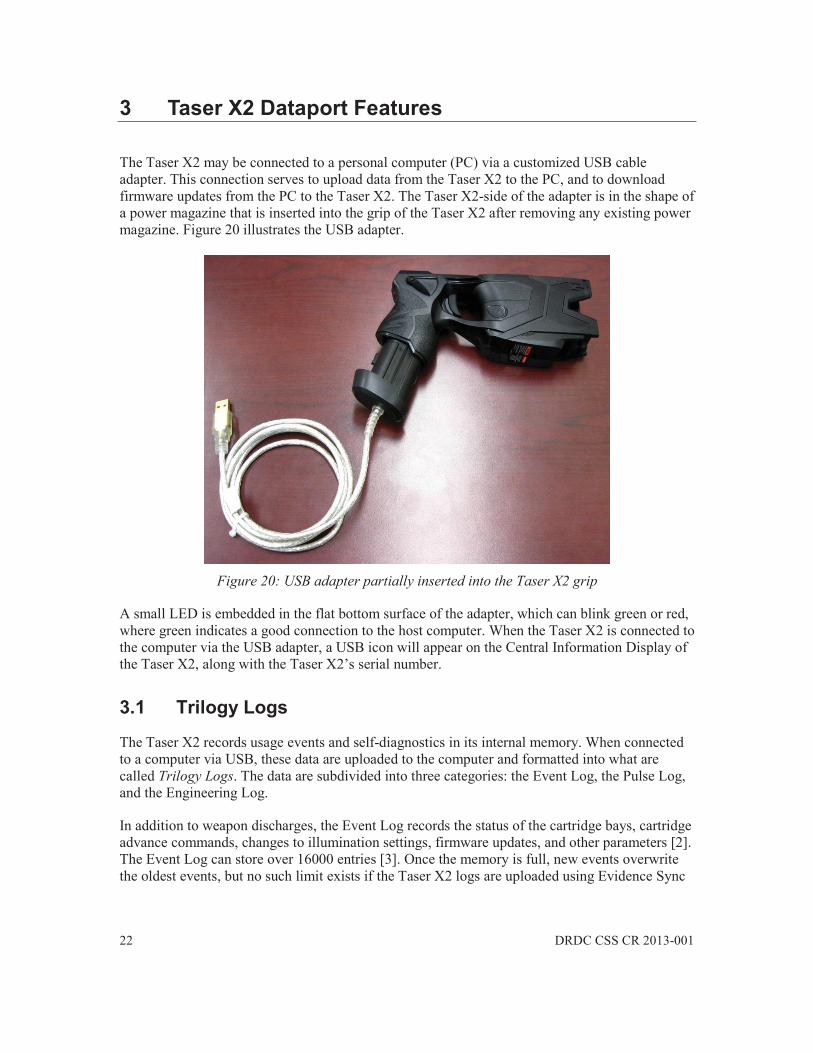
The Taser X2 may be connected to a personal computer (PC) via a customized USB cable adapter. This connection serves to upload data from the Taser X2 to the PC, and to download firmware updates from the PC to the Taser X2. The Taser X2-side of the adapter is in the shape of a power magazine that is inserted into the grip of the Taser X2 after removing any existing power magazine. Figure 20 illustrates the USB adapter.
Figure 20: USB adapter partially inserted into the Taser X2 grip
A small LED is embedded in the flat bottom surface of the adapter, which can blink green or red, where green indicates a good connection to the host computer. When the Taser X2 is connected to the computer via the USB adapter, a USB icon will appear on the Central Information Display of the Taser X2, along with the Taser X2’s serial number.
3.1 Trilogy Logs
The Taser X2 records usage events and self-diagnostics in its internal memory. When connected to a computer via USB, these data are uploaded to the computer and formatted into what are called Trilogy Logs. The data are subdivided into three categories: the Event Log, the Pulse Log, and the Engineering Log.
In addition to weapon discharges, the Event Log records the status of the cartridge bays, cartridge advance commands, changes to illumination settings, firmware updates, and other parameters [2]. The Event Log can store over 16000 entries [3]. Once the memory is full, new events overwrite the oldest events, but no such limit exists if the Taser X2 logs are uploaded using Evidence Sync
DRDC CSS CR 2013-001 23
(described later), hence Evidence Sync uploads are recommended to prevent the loss of older data. An Event Log will be described in Section 3.2.
The Pulse Log records the high voltage pulse activity generated by the Taser X2, including trigger cycles and arc cycles. The voltage of the Taser X2’s capacitors are monitored by internal circuitry, allowing it to estimate whether or not contact was made with a subject, and to estimate the charge delivered by each pulse [2]. The Pulse Log can store approximately 41000 pulses, or the equivalent of 34 minutes of continuous discharge [3]. Unfortunately, it is unknown if the calculated charge is the total charge or the net charge, or if it represents the charge delivered in the entire pulse or only the charge in the main phase. An example of the charge delivered by each pulse of an Taser X2 trigger cycle is given in [3], although only 90 pulses are shown, despite 98 pulses being recorded in trial firings (c.f. Section 5), which begs the question as to whether or not a complete firing record is being shown in [3]. The charge of approximately 65 C per pulse shown in [3] is smaller than the average total charge value of 76 C per pulse recorded during trials (c.f. Section 5.2.5). A Pulse Log will be considered in Section 3.2.
Finally, the Engineering Log contains the results of self-diagnostics performed by the Taser X2. Faults are indicated to the user via icons on the CID and via the Eng Code CID menu item (c.f. Section 2.2.4). The Engineering Log records up to approximately 8200 events [3]. The Engineering Log is only accessible to Taser International factory engineers [3].
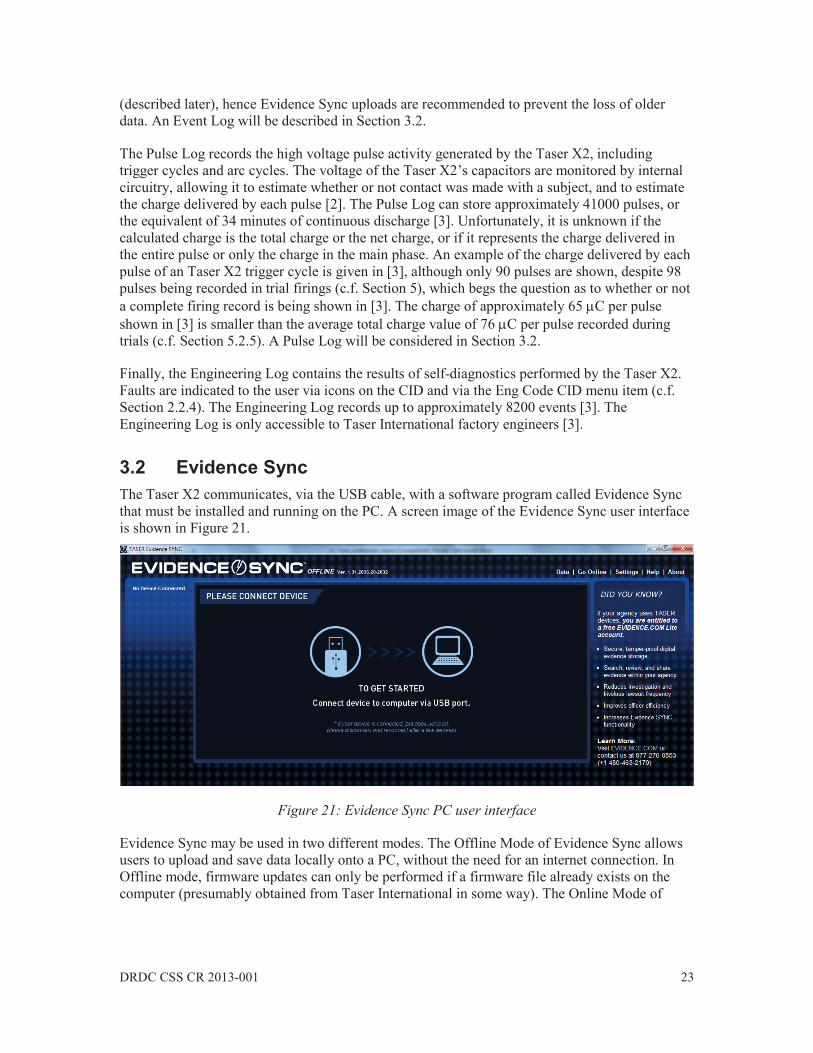
3.2 Evidence Sync The Taser X2 communicates, via the USB cable, with a software program called Evidence Sync that must be installed and running on the PC. A screen image of the Evidence Sync user interface is shown in Figure 21.
Figure 21: Evidence Sync PC user interface
Evidence Sync may be used in two different modes. The Offline Mode of Evidence Sync allows users to upload and save data locally onto a PC, without the need for an internet connection. In Offline mode, firmware updates can only be performed if a firmware file already exists on the computer (presumably obtained from Taser International in some way). The Online Mode of
24 DRDC CSS CR 2013-001
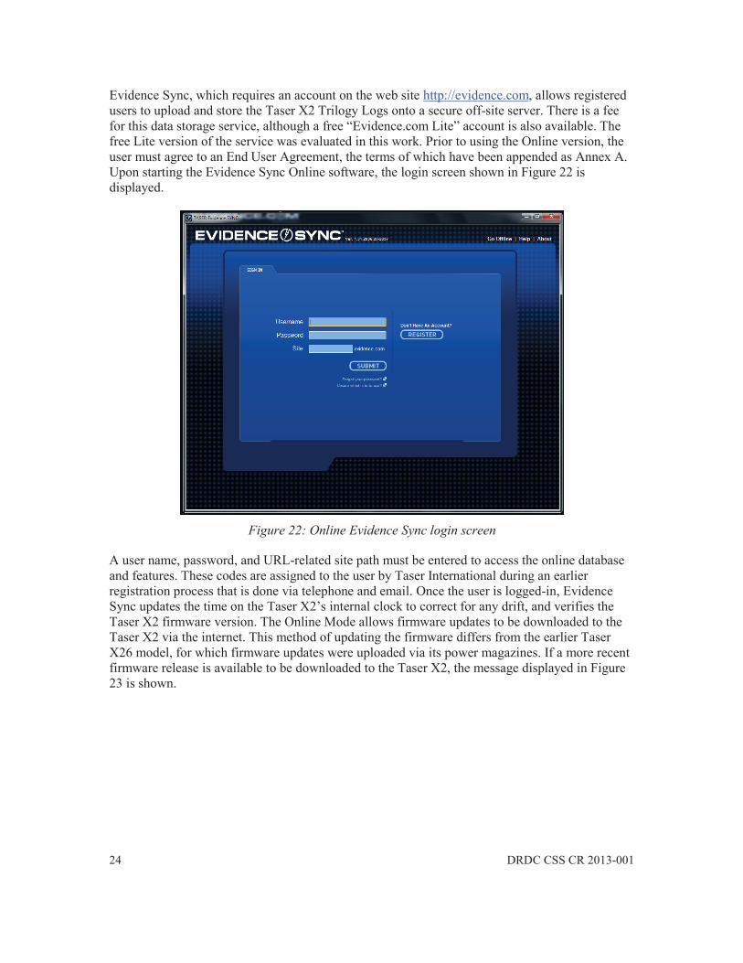
Evidence Sync, which requires an account on the web site http://evidence.com, allows registered users to upload and store the Taser X2 Trilogy Logs onto a secure off-site server. There is a fee for this data storage service, although a free “Evidence.com Lite” account is also available. The free Lite version of the service was evaluated in this work. Prior to using the Online version, the user must agree to an End User Agreement, the terms of which have been appended as Annex A. Upon starting the Evidence Sync Online software, the login screen shown in Figure 22 is displayed.
Figure 22: Online Evidence Sync login screen
A user name, password, and URL-related site path must be entered to access the online database and features. These codes are assigned to the user by Taser International during an earlier registration process that is done via telephone and email. Once the user is logged-in, Evidence Sync updates the time on the Taser X2’s internal clock to correct for any drift, and verifies the Taser X2 firmware version. The Online Mode allows firmware updates to be downloaded to the Taser X2 via the internet. This method of updating the firmware differs from the earlier Taser X26 model, for which firmware updates were uploaded via its power magazines. If a more recent firmware release is available to be downloaded to the Taser X2, the message displayed in Figure 23 is shown.
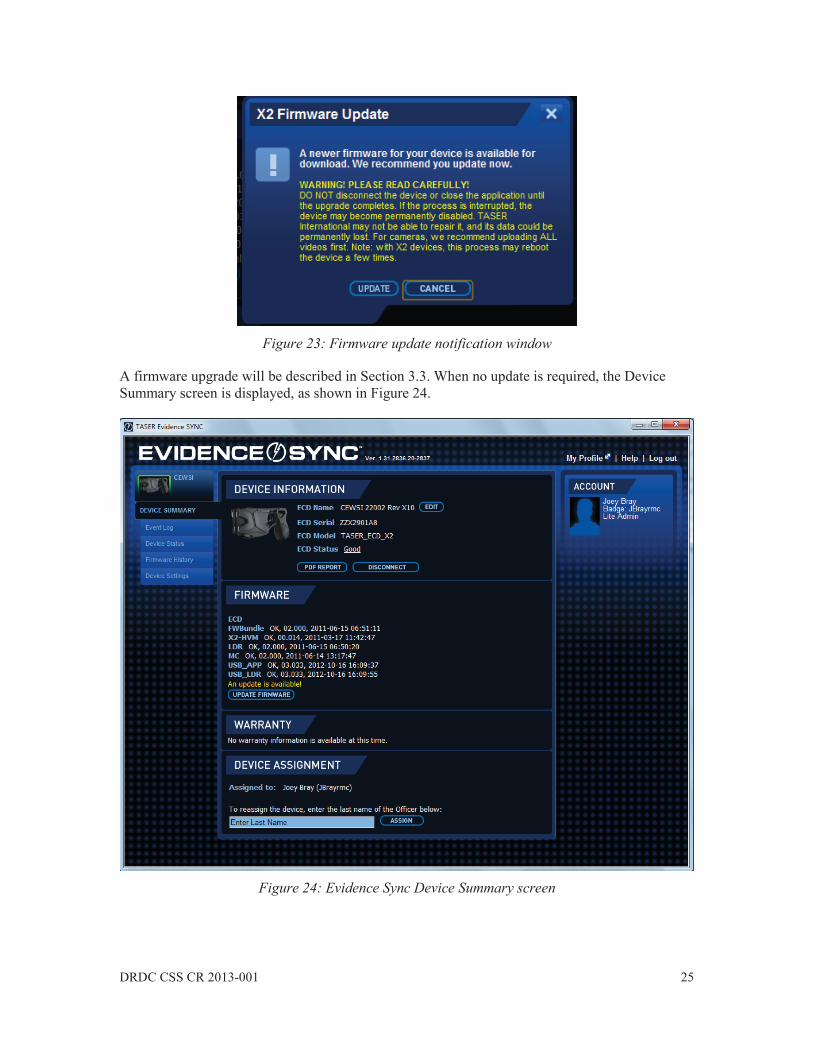
DRDC CSS CR 2013-001 25
Figure 23: Firmware update notification window
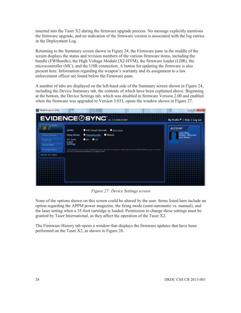
A firmware upgrade will be described in Section 3.3. When no update is required, the Device Summary screen is displayed, as shown in Figure 24.
Figure 24: Evidence Sync Device Summary screen

26 DRDC CSS CR 2013-001
The Device Summary screen displays information regarding the particular Taser X2 weapon that is connected to the USB port. The Device Information pane at the top of the screen displays the CEW model and serial number, in this case serial ZZX2901A8, in addition to the CEW name that had been previously entered into the Evidence.com database by the user. The user can change the name of the device. The Status of the Taser X2, which is displayed here as being “Good”, is related to the Engineering Log, indicating that there is an absence of detected faults on this weapon. Two buttons are located at the bottom of the Device Information pane, namely the Disconnect button that is used to disconnect the Taser X2 from the USB port, and the PDF Report button, which generates a PDF version of what is called the Deployment Log. The Deployment Log, which is not formally a part of the Trilogy Logs, is a record of only a limited set of entries from the more complete Event Log. It is unknown why only certain parameters are included in the Deployment Log. The Deployment Log records the weapon’s 2000 most recent discharge-related events, including: Armed and Safe mode transitions, arc discharges, and trigger pulls. The Deployment Log also records any time synchronizations [2]. Deployment Log events are sequentially numbered. Included with each discharge-related event are: date, time, duration of any discharge, cartridge bay status, weapon temperature, and the percentage battery remaining. The top portion of the Deployment Log obtained by pressing the PDF Report button is shown in Figure 25.

DRDC CSS CR 2013-001 27
Figure 25: Top portion of a Deployment Log showing the earliest entries for the weapon
Unfortunately, ambiguous entries can sometimes appear in the Deployment Log. For instance, a firmware upgrade was performed on the weapon on December 18th at 15h03. The entries in the Deployment Log surrounding this event are shown in Figure 26.
Figure 26: Ambiguous Deployment Log entries
Events numbered 530 and 531 are correct, indicating the USB connection and the automatic time synchronization. Event 532, which indicates Weapon Mode - Hard Stop, is plausible given that the firmware was being upgraded. However, Entry 533, listed as Weapon Mode - 35’ Cart Laser Off, is ambiguous. It is hypothesized that this message relates to a firmware fix in which a laser sight is turned off when a 35-foot cartridge is detected. At no point was a 35-foot cartridge
28 DRDC CSS CR 2013-001
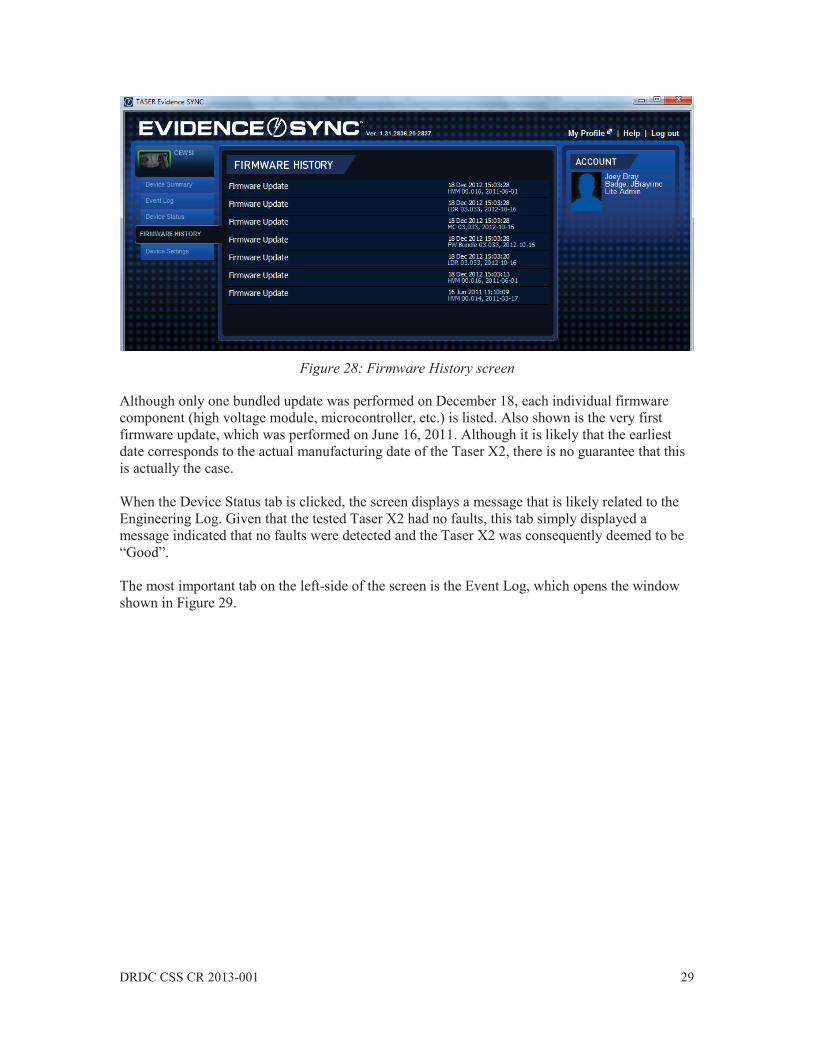
inserted into the Taser X2 during the firmware upgrade process. No message explicitly mentions the firmware upgrade, and no indication of the firmware version is associated with the log entries in the Deployment Log. Returning to the Summary screen shown in Figure 24, the Firmware pane in the middle of the screen displays the status and revision numbers of the various firmware items, including the bundle (FWBundle), the High Voltage Module (X2-HVM), the firmware loader (LDR), the microcontroller (MC), and the USB connection. A button for updating the firmware is also present here. Information regarding the weapon’s warranty and its assignment to a law enforcement officer are found below the Firmware pane. A number of tabs are displayed on the left-hand side of the Summary screen shown in Figure 24, including the Device Summary tab, the contents of which have been explained above. Beginning at the bottom, the Device Settings tab, which was disabled in firmware Version 2.00 and enabled when the firmware was upgraded to Version 3.033, opens the window shown in Figure 27.
Figure 27: Device Settings screen
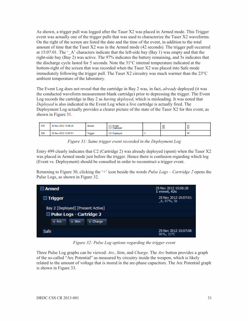
None of the options shown on this screen could be altered by the user. Items listed here include an option regarding the APPM power magazine, the firing mode (semi-automatic vs. manual), and the laser setting when a 35-foot cartridge is loaded. Permission to change these settings must be granted by Taser International, as they affect the operation of the Taser X2. The Firmware History tab opens a window that displays the firmware updates that have been performed on the Taser X2, as shown in Figure 28.
DRDC CSS CR 2013-001 29
Figure 28: Firmware History screen
Although only one bundled update was performed on December 18, each individual firmware component (high voltage module, microcontroller, etc.) is listed. Also shown is the very first firmware update, which was performed on June 16, 2011. Although it is likely that the earliest date corresponds to the actual manufacturing date of the Taser X2, there is no guarantee that this is actually the case. When the Device Status tab is clicked, the screen displays a message that is likely related to the Engineering Log. Given that the tested Taser X2 had no faults, this tab simply displayed a message indicated that no faults were detected and the Taser X2 was consequently deemed to be “Good”. The most important tab on the left-side of the screen is the Event Log, which opens the window shown in Figure 29.

30 DRDC CSS CR 2013-001
Figure 29: Event Log screen
A large quantity of data is available in the Event Log window, and a search/filter tool is provided to the user at the top of the window. As previously mentioned, the Event Log records various device events such as time synchronizations, safety switch toggles, triggers, arc tests, battery replacements, cartridge advances, and firmware updates. Unlike the Deployment Log, the entries in the Event Log are not numbered sequentially. Clicking the ‘+’ icon beside a named event provides more information regarding it, such as the Armed event that is shown in Figure 30.
Figure 30: Details regarding an arming event
DRDC CSS CR 2013-001 31
As shown, a trigger pull was logged after the Taser X2 was placed in Armed mode. This Trigger event was actually one of the trigger pulls that was used to characterize the Taser X2 waveforms. On the right of the screen are listed the date and the time of the event, in addition to the total amount of time that the Taser X2 was in the Armed mode (42 seconds). The trigger pull occurred at 15:07:01. The ‘_A’ characters indicate that the left-side bay (Bay 1) was empty and that the right-side bay (Bay 2) was active. The 97% indicates the battery remaining, and 5s indicates that the discharge cycle lasted for 5 seconds. Note the 31 C internal temperature indicated at the bottom-right of the screen that was recorded when the Taser X2 was placed into Safe mode immediately following the trigger pull. The Taser X2 circuitry was much warmer than the 23 C ambient temperature of the laboratory. The Event Log does not reveal that the cartridge in Bay 2 was, in fact, already deployed (it was the conducted waveform measurement blank cartridge) prior to depressing the trigger. The Event Log records the cartridge in Bay 2 as having deployed, which is misleading. It was noted that Deployed is also indicated in the Event Log when a live cartridge is actually fired. The Deployment Log actually provides a clearer picture of the state of the Taser X2 for this event, as shown in Figure 31.
Figure 31: Same trigger event recorded in the Deployment Log
Entry 499 clearly indicates that C2 (Cartridge 2) was already deployed (spent) when the Taser X2 was placed in Armed mode just before the trigger. Hence there is confusion regarding which log (Event vs. Deployment) should be consulted in order to reconstruct a trigger event. Returning to Figure 30, clicking the ‘+’ icon beside the words Pulse Logs – Cartridge 2 opens the Pulse Logs, as shown in Figure 32.
Figure 32: Pulse Log options regarding the trigger event
Three Pulse Log graphs can be viewed: Arc, Stim, and Charge. The Arc button provides a graph of the so-called “Arc Potential” as measured by circuitry inside the weapon, which is likely related to the amount of voltage that is stored in the arc-phase capacitors. The Arc Potential graph is shown in Figure 33.
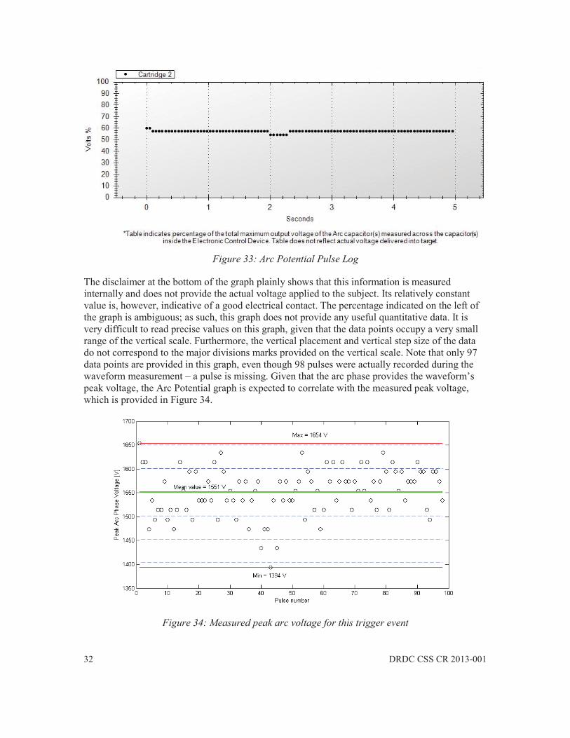
32 DRDC CSS CR 2013-001
Figure 33: Arc Potential Pulse Log
The disclaimer at the bottom of the graph plainly shows that this information is measured internally and does not provide the actual voltage applied to the subject. Its relatively constant value is, however, indicative of a good electrical contact. The percentage indicated on the left of the graph is ambiguous; as such, this graph does not provide any useful quantitative data. It is very difficult to read precise values on this graph, given that the data points occupy a very small range of the vertical scale. Furthermore, the vertical placement and vertical step size of the data do not correspond to the major divisions marks provided on the vertical scale. Note that only 97 data points are provided in this graph, even though 98 pulses were actually recorded during the waveform measurement – a pulse is missing. Given that the arc phase provides the waveform’s peak voltage, the Arc Potential graph is expected to correlate with the measured peak voltage, which is provided in Figure 34.
Figure 34: Measured peak arc voltage for this trigger event

DRDC CSS CR 2013-001 33
Although the Arc Potential indicates that the two first pulses were higher than the rest, the measured peak voltage only shows the very first pulse as having an unusually high value – other pulses have higher measured values than the second pulse, which disagrees with the Arc Potential graph. The Arc Potential indicates that pulses 40 to 45 had unusually low voltage values. In the measured data set, only pulses 40, 43, and 45 had low peak values. As such, there is only a weak correlation between the measured peak voltage values and the Arc Potential Pulse Log. Given this weak correlation, the disclaimer, and the arbitrary units on the Arc Potential Pulse Log, this log is of limited use for testing purposes. The Stim button provides a graph of the so-called “Stimulation Potential” as measured by circuitry inside the weapon, which is likely related to the amount of voltage that is stored in the main-phase capacitors. The Stimulation Potential graph is shown in Figure 35.
Figure 35: Stimulation Potential Pulse Log
Curiously, the Stimulation Potential Log is identical to the Arc Potential Log – whether or not this is an error is a matter of speculation. Again, note the disclaimer at the bottom of the graph, the arbitrary vertical units (%), and the difficulty of reading precise values off of the graph. Only 97 of the 98 recorded pulses are present. The voltage stored by the stimulation capacitors are expected to correlate with the peak (negative) voltage of the main phase, and these measured values are shown in Figure 36 (this graph will be explained in Section 5).

34 DRDC CSS CR 2013-001
Figure 36: Measured peak main phase voltage for this trigger event
This time there is a better correlation between the two graphs. Indeed, the first two measured data points have noticeably stronger negative voltage levels. In addition, the six data points clustered around the “Max -966 V” label, which have weaker than average voltage, are associated with pulse numbers 40 to 45, in agreement with the Stimulation Potential Log. However, the swath of values for all of the other measured data points seem to map to the same constant value in the Stimulation Potential Log. Although there is some correlation of the Stimulation Potential Log to the peak main phase voltage, given the disclaimer, the arbitrary vertical units, the difficulty of reading precise values, and the missing pulse, the Stimulation Potential Log is of limited use for testing purposes. The near constant value of the Stimulation Potential Log may, however, indicate that a sound electrical connection has been made between the weapon and the subject. Finally, the Charge button provides a graph of the Taser X2’s estimated charge, as shown in Figure 37.

DRDC CSS CR 2013-001 35
Figure 37: Charge Pulse Log
Note that a deterministic vertical axis is now provided, in units of microcoulombs ( C). However, it is unknown if this “charge” represents the total charge or of the net charge, or if it represents the charge delivered by both the arc phase and main phase of the pulse, or of only the main phase. This information is not provided. Again, only 97 of the 98 recorded pulses appear in this log. It is also very difficult to accurately read values from this graph, given that the vertical placement of the data points does not align with the vertical scales. Furthermore, the step size in the data appears to be a value that does not correspond to the divisions on the vertical axis. Only five distinct charge levels exist on this graph, estimated to be 58, 61, 64, 67, and 70 C. The highest values (70 C) are obtained from pulse number 2 and number 39. The lowest value of 58 C occurs at pulse number 45. The graph of the measured total charge is shown in Figure 38.
Figure 38: Measured total charge for this trigger event

36 DRDC CSS CR 2013-001
Note that the highest measured charge does indeed correspond with the 2nd pulse, and the lowest measured charge value also occurs at pulse 45, in agreement with the Charge Log. However, the measured charge does not register the 39th pulse as having a high charge value, as indicated in the Charge Log. Hence there is only a partial correlation between the Charge Log and the total charge measurement. Regarding the absolute levels, the measured total charge is consistently higher than what is indicated in the Charge Log, which suggests that the latter may be an estimate of the main phase charge only. Measurements have revealed that the arc phase of this Taser X2 contains a charge of 7.4 C. If 7.4 C is subtracted from the 81.8 C measured total charge for pulse number 2, 74.4
C remains. This is comparable to the approximately 70 C shown for pulse number 2 in the Charge Log, yielding a difference of 6% compared to the measured value. For the minimum value at pulse number 45, subtracting 7.4 C from 69.3 C yields a measured main phase charge of 61.9 C, which is again higher than the Charge Log value of approximately 58 C (difference of 6% compared to the measured value). Although there is partial correlation between the Charge Log and the measured main phase charge, given the disclaimer, the ambiguous definition of “charge”, the difficulty of reading precise values, and the missing pulse, the Charge Log is again deemed to be of limited use for testing purposes. The near constant value of the Charge Log may, however, indicate that a sound electrical connection has been made between the weapon and the subject. An example of a poor connection is shown in Figure 39, which was recorded for a trigger event in which probes were deployed but for which one probe fell to the floor.
Figure 39: Charge Pulse Log for a missed shot
Because no sound electrical contact existed between the two probes, arcing occurred between the lead wires during this trigger event. The poor electrical contact yields a scattered Charge Log. The Arc Potential and Stimulation Potential logs also displayed scattered values for this misfire.

DRDC CSS CR 2013-001 37
3.3 Updating the Firmware
Upon pressing the Update Firmware button in the Device Summary window, a warning window appeared to ensure that the user wanted to proceed with the update. Once launched, the update completed within a minute, and ended by displaying the window shown in Figure 40.
Figure 40: Reconnection message following a firmware update
Disconnecting and reconnecting the Taser X2 caused it to reboot and to upload its logs to the computer. The firmware history was then verified to be correct. There were no issues regarding this procedure.
3.4 Problem Encountered with Evidence Sync Initially, a faulty USB cable prevented the Taser X2 from connecting to the host computer. Instead of recognizing the Taser X2 and downloading its logs, Evidence Sync entered an infinite loop in which the computer screen would repeat “Booting X2” and “Downloading Data”. During this time, the LED on the Taser X2-side of the USB adapter would blink green and red. The Taser X2 had to be unplugged from the computer to stop the loop. Taser International correctly diagnosed the problem, which was resolved when the company delivered a replacement cable.
3.5 Summary
The USB connection between the Taser X2 and the host computer provides many useful features that can be accessed via Evidence Sync. When Evidence Sync is used in the Offline mode, the data from the Taser X2 is saved to the local computer only. If the user has an account on Taser International’s Evidence.com web site, Evidence Sync can be used in the Online mode, in which case the data from the Taser X2 is uploaded to, and archived on, an external Taser International database. Evidence Sync is required to perform all firmware updates on the Taser X2. The firmware updates are available automatically in the Online mode of Evidence Sync only. Both modes of Evidence Sync provide the user with access to the Deployment, Event, and Pulse Logs. The Deployment Log and Event Log, when combined, allow the history of the Taser X2 to be reconstructed. It should be noted that data is poorly distributed between these two logs – they should be consulted together. Ambiguous entries in the Deployment Log were noted relating to a firmware upgrade. Although the Pulse Logs can be accessed via Evidence Sync, they cannot be reliably used for electrical testing purposes.
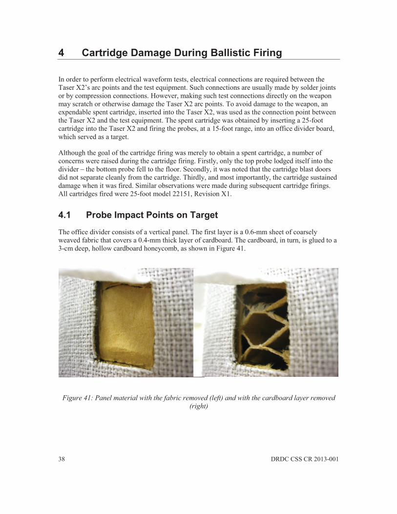
38 DRDC CSS CR 2013-001
4 Cartridge Damage During Ballistic Firing
In order to perform electrical waveform tests, electrical connections are required between the Taser X2’s arc points and the test equipment. Such connections are usually made by solder joints or by compression connections. However, making such test connections directly on the weapon may scratch or otherwise damage the Taser X2 arc points. To avoid damage to the weapon, an expendable spent cartridge, inserted into the Taser X2, was used as the connection point between the Taser X2 and the test equipment. The spent cartridge was obtained by inserting a 25-foot cartridge into the Taser X2 and firing the probes, at a 15-foot range, into an office divider board, which served as a target.
Although the goal of the cartridge firing was merely to obtain a spent cartridge, a number of concerns were raised during the cartridge firing. Firstly, only the top probe lodged itself into the divider – the bottom probe fell to the floor. Secondly, it was noted that the cartridge blast doors did not separate cleanly from the cartridge. Thirdly, and most importantly, the cartridge sustained damage when it was fired. Similar observations were made during subsequent cartridge firings. All cartridges fired were 25-foot model 22151, Revision X1.
4.1 Probe Impact Points on Target
The office divider consists of a vertical panel. The first layer is a 0.6-mm sheet of coarsely weaved fabric that covers a 0.4-mm thick layer of cardboard. The cardboard, in turn, is glued to a 3-cm deep, hollow cardboard honeycomb, as shown in Figure 41.
Figure 41: Panel material with the fabric removed (left) and with the cardboard layer removed (right)

DRDC CSS CR 2013-001 39
The top probe impacted the board with such force, and so deeply, that pliers were required to remove it, as shown in Figure 42.
Figure 42: Top probe embedded into the panel and its impact hole into the cardboard
The bottom probe left a noticeable depression on the fabric surface of the board, and it is unknown why it failed to lodge itself into the panel. The impact point of the bottom probe is shown in Figure 43, which shows a tear in the cardboard layer that was not visible on the fabric surface.
Figure 43: Bottom probe impact point with and without the cardboard layer
The honeycomb structure under the lower probe impact point was visibly depressed. Whether or not the slight tearing of the honeycomb was caused by the probe’s needle is a matter of speculation. There are two possibilities: either the probe did not impact properly due to a misfire, or the elastic reaction of the honeycomb material caused the probe to bounce back out of its hole due to the proximity of a honeycomb rib to the impact point.
Given that the blast doors did not separate cleanly along an edge, and that the cartridge itself sustained damage (as explained in the following section), a misfire cannot be ruled-out. Further ballistic testing is therefore recommended, using a uniform material such as high-density foam as a target.
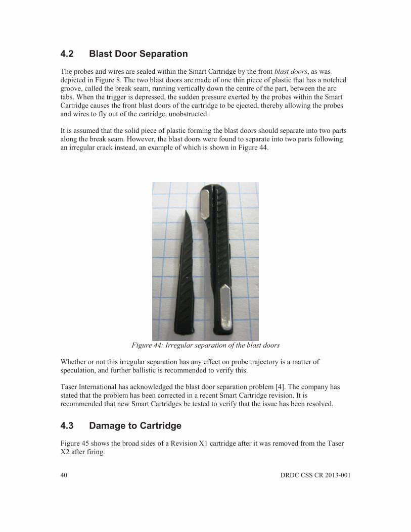
40 DRDC CSS CR 2013-001
4.2 Blast Door Separation
The probes and wires are sealed within the Smart Cartridge by the front blast doors, as was depicted in Figure 8. The two blast doors are made of one thin piece of plastic that has a notched groove, called the break seam, running vertically down the centre of the part, between the arc tabs. When the trigger is depressed, the sudden pressure exerted by the probes within the Smart Cartridge causes the front blast doors of the cartridge to be ejected, thereby allowing the probes and wires to fly out of the cartridge, unobstructed.
It is assumed that the solid piece of plastic forming the blast doors should separate into two parts along the break seam. However, the blast doors were found to separate into two parts following an irregular crack instead, an example of which is shown in Figure 44.
Figure 44: Irregular separation of the blast doors
Whether or not this irregular separation has any effect on probe trajectory is a matter of speculation, and further ballistic is recommended to verify this.
Taser International has acknowledged the blast door separation problem [4]. The company has stated that the problem has been corrected in a recent Smart Cartridge revision. It is recommended that new Smart Cartridges be tested to verify that the issue has been resolved.
4.3 Damage to Cartridge
Figure 45 shows the broad sides of a Revision X1 cartridge after it was removed from the Taser X2 after firing.

DRDC CSS CR 2013-001 41
Figure 45: Images showing both sides of the deployed cartridge, where the circles indicate damage to the two top support rings of the cartridge
The top image of the cartridge depicts the cartridge as it would be inserted into the Taser X2, whereas the bottom image shows the same cartridge rotated to reveal the other side. The two circles indicate areas of damage on the cartridge, in the form of two broken support rings. The damaged support rings are both on the top part of the cartridge, one on either side, where ‘top’ is referenced to how the cartridge sits in the cartridge bay of the Taser X2.
The cartridge is made of two distinct parts. The part on the right of Figure 45 contains the compressed nitrogen cartridge, and contains a cavity in which the probes and lead wires are housed. The part of the left is hollow and slides over the other part, and snaps into place by means of six rings that slide over raised support posts on the other part. The part on the left contains the

42 DRDC CSS CR 2013-001
blast doors and L-shaped metallic arc tabs that form part of the electrical circuit between the Taser X2’s arc points and the probe wires, as shown in Figure 46.
Figure 46: Close-up of a deployed cartridge showing the lead wire attachment. Insets are of a probe and a front view of the same cartridge
Prior to being fired, the top of the cartridge is sealed by its blast doors. However, in Figure 46, the cartridge has been fired, so the blast doors are missing and, instead, the deployed lead wires are visible. Each lead wire terminates inside its probe, which is shown as the bottom inset, and where the grid lines are at ¼-inch intervals. The inset on the right shows the top of the cartridge, viewed from the front. Each lead wire passes through a plastic lanyard loop at the top of the cartridge and is secured in place by a tied knot. No direct electrical connection exists between the L-shaped arc tab on the side of the cartridge and the lead wire. The electrical path is established by arcing between the L-shaped tab and the wire. The cylindrical cavities that house the two probes and the two rectangular cavities that house the bundles of lead wire are also evident on the top of the cartridge in Figure 46.
Figure 47 shows how the two cartridge parts can be separated, which is done by gently prying the support rings of the hollow part over the posts and sliding it out. A broken support ring is plainly evident.
L-shaped tab
lead wire knot
probe cavity wire bundle cavities
probe cavity
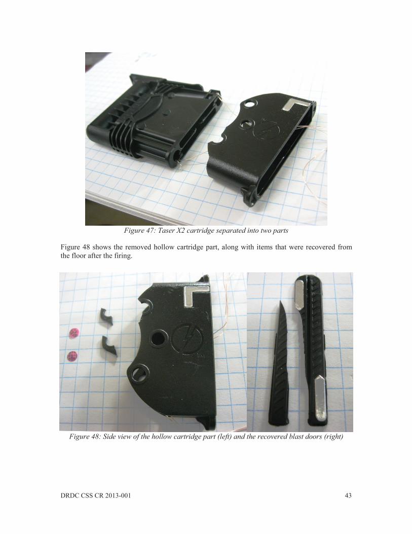
DRDC CSS CR 2013-001 43
Figure 47: Taser X2 cartridge separated into two parts
Figure 48 shows the removed hollow cartridge part, along with items that were recovered from the floor after the firing.
Figure 48: Side view of the hollow cartridge part (left) and the recovered blast doors (right)

44 DRDC CSS CR 2013-001
The two pink round items on the far left are the AFID (anti-felon identification) tags that are released from the cartridge upon firing. The two small hook-shaped items are the recovered broken support rings. On the far right of the image are the ejected blast doors. Figure 49 shows how a cartridge sits in one of the Taser X2’s cartridge bays, and the inset shows the cartridge inserted half-way into the Taser X2 body, as viewed from the side.
Figure 49: Close-up of the top-front of the Taser X2, where the cartridge L-shaped tab meets the Taser X2 arc point. The inset is a side view of a cartridge partially inserted into the Taser X2
When the cartridge is fully inserted, there is a small gap between the cartridge’s L-shaped tab and the arc point of the Taser X2, which indicates that small arcs are necessary to bridge: the gap between the arc point and the L-shaped tab, and the gap between the L-shaped tab and the lead wire (or the blast door tab for a warning arc). The arc phase of the Taser X2’s waveform generates sufficient voltage to establish these arcs under normal operation.
The potentially adverse effects of the broken cartridge support rings can now be explained. If a sufficient number of rings are broken, the possibility exists that the hollow part of the cartridge could be displaced, or even ejected from the weapon, caused by the sudden pressure of the release of the compressed nitrogen gas inside the cartridge itself. If this were to happen, a possible sequence of events leading to ejection is depicted in Figure 50. The sequence begins by assuming that a firing has just taken place, and that a sufficient number of rings have broken from the hollow cartridge part, giving it freedom of movement.
Taser X2 body cartridge in left bay
empty right bay
X2 body arc point
cartridge L-shaped tab

DRDC CSS CR 2013-001 45
Figure 50: Simulated ejection sequence of hollow cartridge part
In this image, the hollow part of the cartridge has detached and has moved forward due to the internal cartridge gas pressure. This creates larger than normal gaps between the Taser X2 arc point and the L-shaped tab, and also extends the gap between the L-shaped tab and the lead wires. This might interrupt the current flow.
Here, the hollow cartridge part has moved sufficiently forward to expose the lead wire behind it, which might re-establish the arc between the arc point and the lead wire.
The final image depicts the hollow cartridge having been fully ejected from the Taser X2. Given that both the lead wires pass through it, the possibility exists that the hollow part may interfere with the deployed wires.
The exact cause of the damage to the support rings is unknown. Possible causes include: an over-pressurized nitrogen gas cylinder, an improper or delayed release of the blast door, an existing hairline crack in the support ring, or a support ring plastic that is too weak to sustain the forces exerted during firing.
Taser International has acknowledged the support ring problem and has stated that it will be corrected in 2013 when a new Smart Cartridge revision is released [4]. This will not correct any legacy cartridges that are in inventory.

46 DRDC CSS CR 2013-001
5 Electrical Waveform Measurement
The electrical waveforms presented herein were recorded following a trigger-pull event, with a 600- non-inductive power resistor connected between the arc points of the Taser X2. The 600- resistor is identical to that recommended for Taser X26 waveform testing [6].
5.1 Test Bench
Voltage measurements across the load resistor were performed using a high-voltage probe connected to a digital sampling oscilloscope. The voltage probe contacted the leads of the 600- resistor that was, in turn, connected in shunt across one of the Taser X2 arc point pairs, by means of an intermediate spent cartridge inserted into one of the Taser X2’s cartridge bays. The setup is depicted conceptually in Figure 51, whereas Figure 52 is an image of the actual test bench.
Figure 51: Conceptual diagram of the electrical test apparatus
Figure 52: Photograph of the test bench apparatus
Oscilloscope
X2 Taser Wires
600
High voltage probe
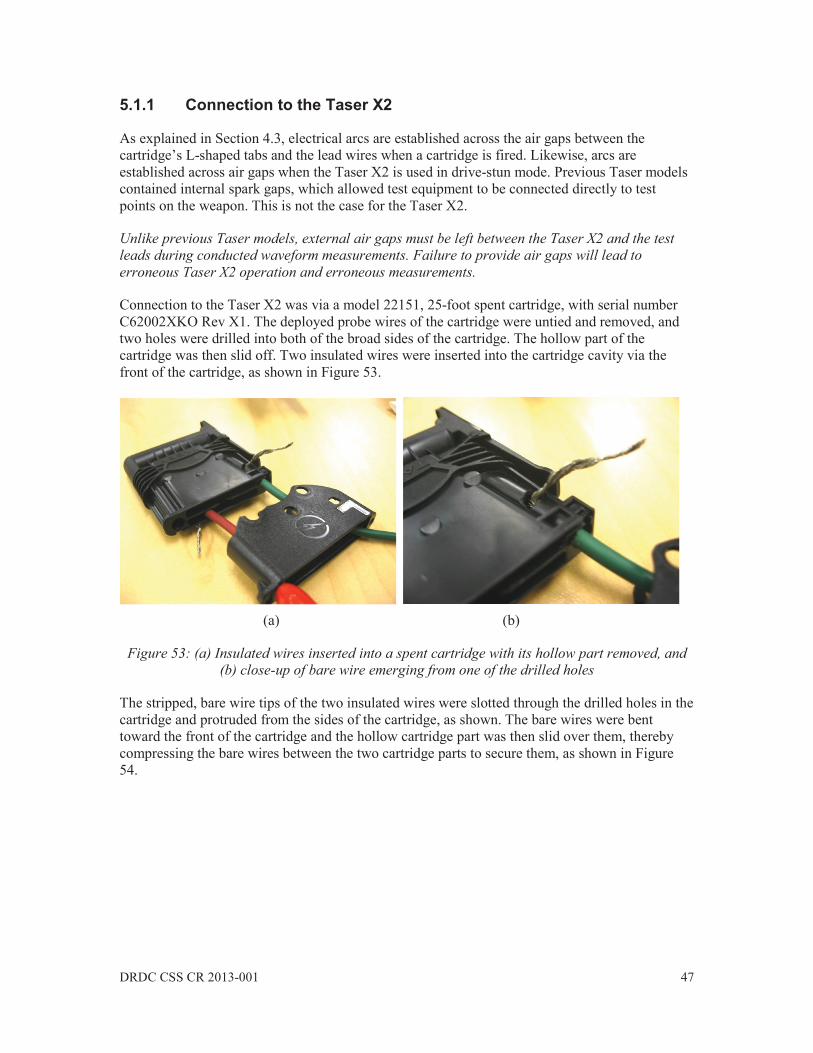
DRDC CSS CR 2013-001 47
5.1.1 Connection to the Taser X2
As explained in Section 4.3, electrical arcs are established across the air gaps between the cartridge’s L-shaped tabs and the lead wires when a cartridge is fired. Likewise, arcs are established across air gaps when the Taser X2 is used in drive-stun mode. Previous Taser models contained internal spark gaps, which allowed test equipment to be connected directly to test points on the weapon. This is not the case for the Taser X2.
Unlike previous Taser models, external air gaps must be left between the Taser X2 and the test leads during conducted waveform measurements. Failure to provide air gaps will lead to erroneous Taser X2 operation and erroneous measurements.
Connection to the Taser X2 was via a model 22151, 25-foot spent cartridge, with serial number C62002XKO Rev X1. The deployed probe wires of the cartridge were untied and removed, and two holes were drilled into both of the broad sides of the cartridge. The hollow part of the cartridge was then slid off. Two insulated wires were inserted into the cartridge cavity via the front of the cartridge, as shown in Figure 53.
(a) (b)
Figure 53: (a) Insulated wires inserted into a spent cartridge with its hollow part removed, and (b) close-up of bare wire emerging from one of the drilled holes
The stripped, bare wire tips of the two insulated wires were slotted through the drilled holes in the cartridge and protruded from the sides of the cartridge, as shown. The bare wires were bent toward the front of the cartridge and the hollow cartridge part was then slid over them, thereby compressing the bare wires between the two cartridge parts to secure them, as shown in Figure 54.

48 DRDC CSS CR 2013-001
(a) (b)
Figure 54: (a) Test cartridge with hollow part re-attached, with bare wires emerging from the front, and (b) close-up of one of the bare wires emerging very near to the conductive L-shaped
pad without touching it.
A small gap of approximately 1-mm long was created between the bare test lead wires and the L-shaped tabs of the cartridge. The test cartridge was then inserted into the Taser X2 for testing, as shown in Figure 55.
(a) (b)
Figure 55: (a) Test cartridge inserted into the right-side bay of the Taser X2, and (b) close-up showing the small gap that is maintained between the bare test lead wire and the tab of the
cartridge
Arcs were clearly visible between the bare wires and the cartridge tabs during firing, and repeatable measurements were obtained using this method.

DRDC CSS CR 2013-001 49
5.1.2 Oscilloscope Make Tektronix Model DPO4104B Serial C021569 Age New from the box. Powered up Oct 22 2012 Calibration (on file) Tektronix Certificate PCXPT1L7BH dated: Sept 17 2012 Analog bandwidth Set to 20 MHz Sample rate Set to 2 million samples per second Record length Set to 20 million samples Horizontal time step 0.5 s/sample Vertical scale 500 mV/division Resolution 8 bits per sample Coupling DC Trigger Edge, DC, 50 mV level, normal mode Input impedance 1 M Conditioning None. Raw data recorded.
5.1.3 High Voltage Probe Make Tektronix Model P6015A Serial C066270 Age New from the box. Opened Oct 22 2012 Calibration (on file) Tektronix Certificate PCXPS73VWQ dated: Dec 20 2011 Compensation Automatically applied by the oscilloscope Maximum voltage 20 kV DC / 40 kV peak (100 ms pulse width) Voltage reduction 1000:1 Bandwidth 75 MHz
5.1.4 Power Resistor Make Ohmite Series 200 Brown Devil vitreous enamel, ceramic core Model B12NJ600R Resistance 600 5% Wattage 12 watts RMS Winding Non-inductive Measured 603 with negligible inductance, as per HP4262A LCR-meter
5.1.5 Conducted Energy Weapon Make Taser Model Taser X2 Quantity 2 Serials ZZX2901A8 and ZZX2901AX, 22002 Rev X10 Firmware V2.000 Power magazine TPPM: Serial E18018287, 99% charge level 8.913 V
50 DRDC CSS CR 2013-001
Eng code all zeros Arc tests Pass Test date 26 November 2012 Test location Sawyer 5100 laboratory, Royal Military College of Canada Ambient temperature 23 C Bench surface non-conducting wood laminate
5.1.6 Note Regarding Quantization Error Peak voltages of up to 2000 volts are expected from the Taser X2 with the 600 attached. This dictates the use of the 500 mV/division vertical scale, which actually represents 500 V/division after multiplying by the probe’s 1000-times multiplication factor. The oscilloscope has 10.24 vertical divisions, and an 8-bit resolution yields a least-significant bit voltage of 10.24 divisions 500 V/division / 28 bits = 20 V/bit. This means that the voltage resolution of the measurements is no more than 20 volts. In comparison with the peak expected voltage of 2000 V, this represents only 1%, although the relative error obviously increases as the voltage levels subside. In these measurements, the zero-volt level does not exist – it is contained between the +/ 10 V levels. In the absence of signal, the voltage oscillated between +/ 10 V from sample to sample. Total charge calculations were not conducted in the +/ 10 V range to avoid noise accumulation. Using an oscilloscope with a higher bit resolution will improve the quantization error. For example, an 11-bit oscilloscope would have a resolution of 2.5 V for the same settings. Although this currently represents a higher-end oscilloscope, future technology may render this possible at a reasonable cost.
5.1.7 Note Regarding Probes
The P6015A probe that was used for these measurements is but one of many probes that may be suitable for use. The P6015A is a single-ended probe, whereas the output of the Taser X2 is differential. It may be worthwhile to test different types of probes, including differential ones, to see if there are any improvements or cost-savings to be had.
Although a current probe was also tested, it was found to yield excessively noisy measurements and was not included in subsequent measurements. More research is recommended to determine the suitability of current probes.
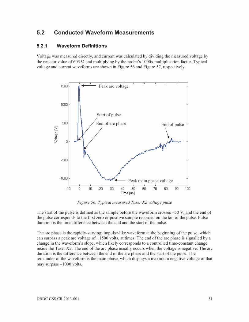
DRDC CSS CR 2013-001 51
5.2 Conducted Waveform Measurements
5.2.1 Waveform Definitions
Voltage was measured directly, and current was calculated by dividing the measured voltage by the resistor value of 603 and multiplying by the probe’s 1000x multiplication factor. Typical voltage and current waveforms are shown in Figure 56 and Figure 57, respectively.
Figure 56: Typical measured Taser X2 voltage pulse
The start of the pulse is defined as the sample before the waveform crosses +50 V, and the end of the pulse corresponds to the first zero or positive sample recorded on the tail of the pulse. Pulse duration is the time difference between the end and the start of the pulse. The arc phase is the rapidly-varying; impulse-like waveform at the beginning of the pulse, which can surpass a peak arc voltage of +1500 volts, at times. The end of the arc phase is signalled by a change in the waveform’s slope, which likely corresponds to a controlled time-constant change inside the Taser X2. The end of the arc phase usually occurs when the voltage is negative. The arc duration is the difference between the end of the arc phase and the start of the pulse. The remainder of the waveform is the main phase, which displays a maximum negative voltage of that may surpass 1000 volts.
End of arc phase End of pulse
Peak arc voltage
Peak main phase voltage
Start of pulse

52 DRDC CSS CR 2013-001
Note that the waveforms are often quite noisy around a zero-crossing. It is hypothesized that this is due to the spark gaps between the weapon and the test leads. Electrical arcs are not well-controlled, and tend to extinguish themselves near a zero-current crossing. The noise may be due to the arc being suddenly extinguished and re-established near the zero crossings.
Figure 57: Typical calculated Taser X2 current pulse
The total charge per pulse is defined as the summation of the magnitude of the current samples over the entire pulse duration, multiplied by the time step. In this calculation, the current is modelled as a staircase function over each sample period, with the magnitude of the current in the interval m being that current measured at the m + 1 sample point. Using this method, the current value of the sample marking the start of the pulse is discarded, being near zero anyway. The pulse repetition interval (PRI) is the time between successive peak arc voltage measurements. In the graphs that follow, zero-time is usually referenced to the sample corresponding to the peak arc voltage. The pulse repetition frequency (PRF) is the reciprocal of the PRI. A typical Taser X2 trigger pull produces 98 individual pulses during the 5-second firing cycle. Given this, statistics can be applied to all of the parameters listed above, including the maximum, minimum, mean value, and the standard deviation. Given that the record length on the oscilloscope is 10 seconds, all of the pulses in the 5-second firing cycle are captured and analyzed.
End of arc phase End of pulse
Peak arc current
Peak main phase current
Start of pulse

DRDC CSS CR 2013-001 53
5.2.2 Serial ZZX2901A8 Right Side Bay Waveforms and Mean Values All 98 voltage waveforms from a 5-second trigger pull are shown superimposed in Figure 58.
Figure 58: Overlay of all 98 pulses contained in a 5-second discharge from the right-side bay
No spurious waveforms, or missed pulses were observed during the trigger pulls. Although the pulses are generally quite similar to each other, there are deviations nonetheless. The peak arc voltage and peak main phase voltage levels are variable, and there is a significant amount of noise related to the end of the pulse due to the zero crossing. Average values for the waveform parameters are listed in Table 3 for one trigger pull for the right-side bay.
Table 3: Mean values of the measured parameters for right-side bay trigger pull
Number of pulses PRF PRI Peak Arc Phase
Voltage Peak Main
Phase Voltage
98 19.2 Hz 52.0 ms 1563 V 1065 V
Pulse Length
Arc Phase Duration
Total Charge
Peak Arc Phase Current
Peak Main Phase Current
88.8 s 6.6 s 77 C 2.59 A 1.77 A

54 DRDC CSS CR 2013-001
5.2.3 Right Cartridge Bay Peak Arc Phase Voltage The distribution of the peak arc voltage around its mean of 1563 V is shown in Figure 59, where dashed lines indicate multiples of the standard deviation = 45.9 V. The maximum recorded arc voltage of 1634 V (+4.5% above the mean) occurs 11 times in the discharge cycle. This maximum peak voltage corresponds to a maximum peak current of 2.71 A. The minimum arc voltage of 1434 V is 8.3% below the mean. A total of 52 of the 98 peak arc voltages are within one standard deviation of the mean.
Figure 59: Arc phase peak voltage of all 98 pulses contained in a 5-second discharge cycle from
the right-side bay
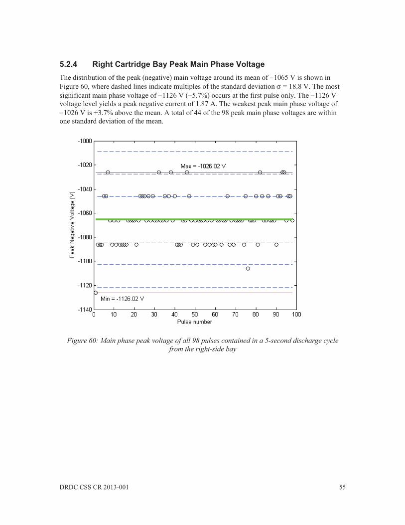
DRDC CSS CR 2013-001 55
5.2.4 Right Cartridge Bay Peak Main Phase Voltage The distribution of the peak (negative) main voltage around its mean of 1065 V is shown in Figure 60, where dashed lines indicate multiples of the standard deviation = 18.8 V. The most significant main phase voltage of 1126 V ( 5.7%) occurs at the first pulse only. The 1126 V voltage level yields a peak negative current of 1.87 A. The weakest peak main phase voltage of
1026 V is +3.7% above the mean. A total of 44 of the 98 peak main phase voltages are within one standard deviation of the mean.
Figure 60: Main phase peak voltage of all 98 pulses contained in a 5-second discharge cycle
from the right-side bay
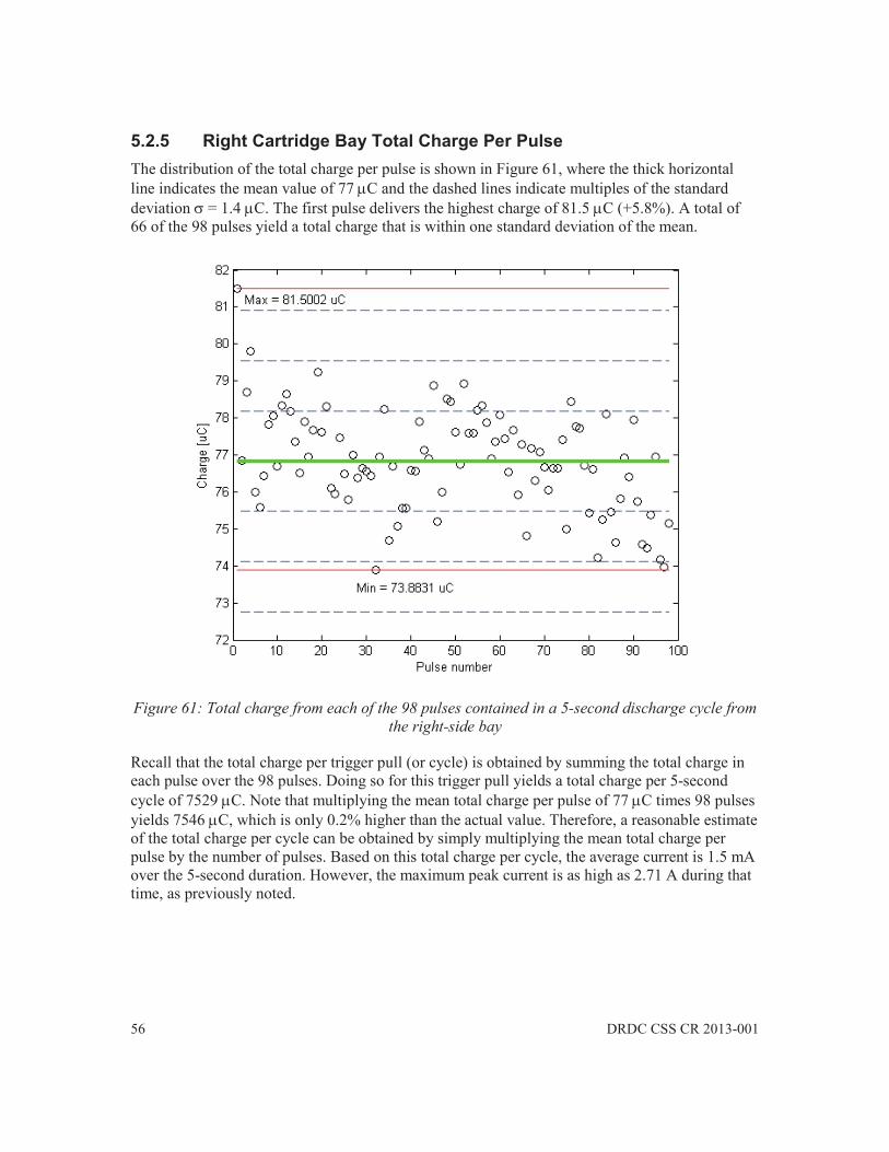
56 DRDC CSS CR 2013-001
5.2.5 Right Cartridge Bay Total Charge Per Pulse The distribution of the total charge per pulse is shown in Figure 61, where the thick horizontal line indicates the mean value of 77 C and the dashed lines indicate multiples of the standard deviation = 1.4 C. The first pulse delivers the highest charge of 81.5 C (+5.8%). A total of 66 of the 98 pulses yield a total charge that is within one standard deviation of the mean.
Figure 61: Total charge from each of the 98 pulses contained in a 5-second discharge cycle from
the right-side bay
Recall that the total charge per trigger pull (or cycle) is obtained by summing the total charge in each pulse over the 98 pulses. Doing so for this trigger pull yields a total charge per 5-second cycle of 7529 C. Note that multiplying the mean total charge per pulse of 77 C times 98 pulses yields 7546 C, which is only 0.2% higher than the actual value. Therefore, a reasonable estimate of the total charge per cycle can be obtained by simply multiplying the mean total charge per pulse by the number of pulses. Based on this total charge per cycle, the average current is 1.5 mA over the 5-second duration. However, the maximum peak current is as high as 2.71 A during that time, as previously noted.

DRDC CSS CR 2013-001 57
5.2.6 Right Cartridge Bay PRI and PRF The distribution of the PRI is shown in Figure 62, where the mean value is 52 ms and the standard deviation is = 0.6 ms. A total of 75 of the 98 pulses fall within one standard deviation of the mean. The first pulse has the shortest interval time of 50.2 ms, and only one other major outlier is noted. The mean PRI yields a PRF of 19.2 Hz. Based on single interval extrema, the lowest PRF is 17.7 Hz and the highest PRF is 19.9 Hz.
Figure 62: Pulse repetition interval of all 97 inter-pulse periods contained in a 5-second
discharge cycle from the right-side bay
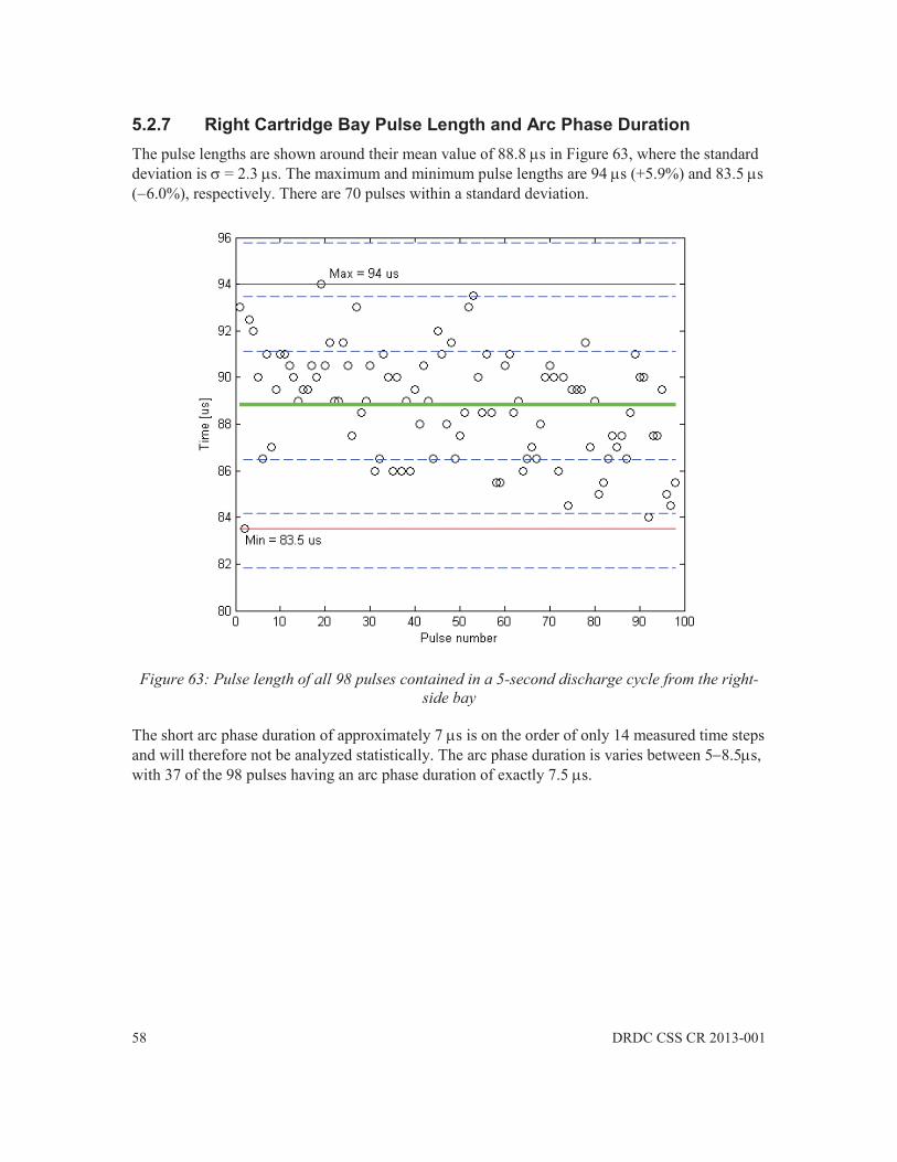
58 DRDC CSS CR 2013-001
5.2.7 Right Cartridge Bay Pulse Length and Arc Phase Duration The pulse lengths are shown around their mean value of 88.8 s in Figure 63, where the standard deviation is = 2.3 s. The maximum and minimum pulse lengths are 94 s (+5.9%) and 83.5 s ( 6.0%), respectively. There are 70 pulses within a standard deviation.
Figure 63: Pulse length of all 98 pulses contained in a 5-second discharge cycle from the right-
side bay
The short arc phase duration of approximately 7 s is on the order of only 14 measured time steps and will therefore not be analyzed statistically. The arc phase duration is varies between 5 8.5 s, with 37 of the 98 pulses having an arc phase duration of exactly 7.5 s.
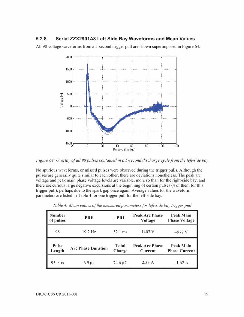
DRDC CSS CR 2013-001 59
5.2.8 Serial ZZX2901A8 Left Side Bay Waveforms and Mean Values All 98 voltage waveforms from a 5-second trigger pull are shown superimposed in Figure 64.
Figure 64: Overlay of all 98 pulses contained in a 5-second discharge cycle from the left-side bay
No spurious waveforms, or missed pulses were observed during the trigger pulls. Although the pulses are generally quite similar to each other, there are deviations nonetheless. The peak arc voltage and peak main phase voltage levels are variable, more so than for the right-side bay, and there are curious large negative excursions at the beginning of certain pulses (4 of them for this trigger pull), perhaps due to the spark gap once again. Average values for the waveform parameters are listed in Table 4 for one trigger pull for the left-side bay.
Table 4: Mean values of the measured parameters for left-side bay trigger pull
Number of pulses PRF PRI Peak Arc Phase
Voltage Peak Main
Phase Voltage
98 19.2 Hz 52.1 ms 1407 V 977 V
Pulse Length Arc Phase Duration Total
Charge Peak Arc Phase
Current Peak Main
Phase Current
95.9 s 6.9 s 74.6 C 2.33 A 1.62 A

60 DRDC CSS CR 2013-001
The number of pulses, PRF and PRI are identical to those of the right-side bay. The mean peak arc voltage of 1407 V is 10% lower than the right bay’s mean of 1563 V. The left bay’s mean peak main phase voltage of 977 V is 8% less in magnitude than the right bay’s value of
1065 V. The left bay pulse length of 95.9 s is 7.4% longer than the 88.8 s pulse length in the right bay. The mean total charge of 74.6 C delivered by the left bay compares very well to the 77 C delivered by the right bay.
5.2.9 Left Cartridge Bay Peak Arc Phase Voltage The distribution of the peak arc voltage for the left-side bay is shown in Figure 65, where the solid green line indicates the mean value of 1407 V and the dashed lines indicate multiples of the standard deviation = 95.0 V. Apart from two strong outliers, the peak voltages are approximately 10% less than that of the right-side bay. A total of 84 of the 98 recorded peaks are within one standard deviation of the mean.
Figure 65: Arc phase peak voltage of all 98 pulses contained in a 5-second discharge cycle from
the left-side bay

DRDC CSS CR 2013-001 61
5.2.10 Left Cartridge Bay Peak Main Phase Voltage The distribution of the peak main phase voltage is shown in Figure 66. The mean is 977 V and the standard deviation is only = 46.0 V. The mean peak main phase voltage of the left-side bay is 8% weaker than the 1065 V mean of the right-side bay. The strongest values are found during the first two pulses only. A total of 50 of the 98 pulses are within a standard deviation of the mean.
Figure 66: Main phase peak voltage of all 98 pulses contained in a 5-second discharge cycle
from the left-side bay

62 DRDC CSS CR 2013-001
5.2.11 Left Cartridge Bay Total Charge Per Pulse The total charge is shown in Figure 67, which has a mean of 74.6 C and a standard deviation of
= 3.2 C. Similar to the right-side bay, the first few pulses produce the highest charge, being 86 C in this case for the first pulse. The total charge population is more clustered for the left-side
bay than it is for the right-side bay. A total of 7308 C of charge was produced for this trigger pull, compared to the 7529 C produced by the right-side bay. A total of 61 of the 98 pulses are within one standard deviation of the mean.
Figure 67: Total charge from each of the 98 pulses contained in a 5-second discharge cycle from
the left-side bay
5.2.12 Left Cartridge Bay PRI and PRF The pulse repetition interval (PRI) and pulse repetition frequency (PRF) are very similar to those obtained from the right-side bay and are consequently not shown here.

DRDC CSS CR 2013-001 63
5.2.13 Left Cartridge Bay Pulse Length Finally, the pulse length distribution for the left-side bay is shown in Figure 68, where the mean is 95.9 s (7.4% longer than that of the right-side bay) and the standard deviation is = 2.8 s.
Figure 68: Pulse length of all 98 pulses contained in a 5-second discharge cycle from the left-side
bay
5.2.14 Sequential Trigger Pulls and Different Taser X2 Serials
Three separate triggers pulls were recorded for each bay for the two Taser X2 serials. Given that PRF is very stable, only the mean peak voltage, mean total charge, mean charge in the arc phase, and mean pulse length are tabulated in Table 5. The values in the cells are the mean values computed across the 98 pulses in the discharge cycle. The values at the bottom of the table are the average of the means, and the worse deviation of the means. Given the averaging, individual pulses within may exceed these values.
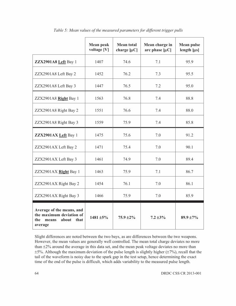
64 DRDC CSS CR 2013-001
Table 5: Mean values of the measured parameters for different trigger pulls
Mean peak voltage [V]
Mean total charge [ C]
Mean charge in arc phase [ C]
Mean pulse length [ s]
ZZX2901A8 Left Bay 1 1407 74.6 7.1 95.9
ZZX2901A8 Left Bay 2 1452 76.2 7.3 95.5
ZZX2901A8 Left Bay 3 1447 76.5 7.2 95.0
ZZX2901A8 Right Bay 1 1563 76.8 7.4 88.8
ZZX2901A8 Right Bay 2 1551 76.6 7.4 88.0
ZZX2901A8 Right Bay 3 1559 75.9 7.4 85.8
ZZX2901AX Left Bay 1 1475 75.6 7.0 91.2
ZZX2901AX Left Bay 2 1471 75.4 7.0 90.1
ZZX2901AX Left Bay 3 1461 74.9 7.0 89.4
ZZX2901AX Right Bay 1 1463 75.9 7.1 86.7
ZZX2901AX Right Bay 2 1454 76.1 7.0 86.1
ZZX2901AX Right Bay 3 1466 75.9 7.0 85.9
Average of the means, and the maximum deviation of the means about that average
1481 5% 75.9 2% 7.2 3% 89.9 7%
Slight differences are noted between the two bays, as are differences between the two weapons. However, the mean values are generally well controlled. The mean total charge deviates no more than 2% around the average in this data set, and the mean peak voltage deviates no more than
5%. Although the maximum deviation of the pulse length is slightly higher ( 7%), recall that the tail of the waveform is noisy due to the spark gap in the test setup, hence determining the exact time of the end of the pulse is difficult, which adds variability to the measured pulse length.

DRDC CSS CR 2013-001 65
This data set indicates that, on average, the Taser X2 generates approximately 1500 V of peak voltage, delivers approximately 2.5 A of peak current and 76 C of total charge (7.0 C of which is contained in the arc phase), and produces a pulse length of approximately 90 s.
The extreme values of the peak arc voltages measured in individual pulses were 1276 V minimum and 2555 V maximum. The extreme values of the total charge measured in individual pulses were 68.9 C minimum and 87.4 C maximum.

66 DRDC CSS CR 2013-001
6 Conclusions and Recommendations
The Taser X2 is a sophisticated CEW that differs in many ways compared to earlier Taser models. Although the main purpose, and principle of operation, of the weapon remain unchanged, increased functionality is provided by the Taser X2’s two cartridge bays, its dual lasers, its new arc buttons, its power magazines, and its ability to be used in drive-stun mode without expending a live cartridge. The Taser X2’s connectivity to the Evidence Sync software allows the history of the device usage to be readily monitored, and provides direct internet access to the latest firmware updates.
The Taser X2 model applies a lower amount of total charge to a subject compared to earlier Taser models. A triggered discharge cycle, which lasts for 5 seconds, delivers 98 pulses. For the two weapons that were tested in this study, an average mean total charge of 75.9 C per pulse was delivered into a 603 load. The average mean peak voltage was 1481 V, and the average mean pulse length was 89.9 s.
A number of concerns were raised during the testing of the Taser X2. Some mechanical aspects of the Taser X2 may lead to unexpected operation. In Section 2.2.1, it was noted that the safety switch can be easily moved between the armed and safe modes of operation. There is a risk that the mode of the Taser X2 could be inadvertently changed by merely brushing it against an object. A more rugged safety switch, one that offers more resistance and a more substantial break between states, could reduce this risk. In Section 2.2.7, it was noted that the temptation exists to insert the PPM using only a slapping force, similar to loading a 9-mm pistol magazine. Using a slapping action to insert the PPM may be insufficient to fully seat the PPM. When a PPM is not fully seated, the risk exists that power to the Taser X2 could be suddenly lost, perhaps during a critical moment. Users should be adequately trained regarding the proper PPM seating method, and should carefully inspect the magazine release button to ensure that it is flush with the grip before using the Taser X2.
Significant concerns were raised in Section 4 regarding the Revision X1 Smart Cartridges. During testing, it was discovered that the cartridge blast doors did not separate as expected from the cartridge, and that the cartridge sustained damage to its support rings. These observations suggest that Smart Cartridge design flaws are present. Taser International claims that more recent cartridge revisions have/will solve these problems.
As reported in Section 2.2.3, a large number of firing mode, cartridge bay, and cartridge type combinations exist for the Taser X2, which could lead to operational confusion in a high stress situation. For example, should the arc button be depressed, or the trigger button? Which cartridge fires first? Etc. This is a direct consequence of the increased functionality that is provided by the Taser X2.
In Section 3.2, concerns were raised regarding the logs that are provided by the Evidence Sync software. The two logs that record the usage history of the Taser X2, namely the Deployment Log and the Event Log, are mostly duplicates of one another; however, certain information can only be found in one of the two logs. For example, only the Deployment Log clearly indicates the state of the cartridge bays prior to a trigger event. Furthermore, ambiguous log entries exist, such as

DRDC CSS CR 2013-001 67
one found in the Deployment Log when a firmware update was applied to the Taser X2. Although the Pulse Logs provide some information regarding the voltage levels inside the Taser X2 and the charge delivered to the subject, these were found to be inadequate for testing purposes: a pulse was consistently missing from the logs, the voltage levels were arbitrary and difficult to read, and the definition of charge was ambiguous. The Pulse Logs are, however, likely useful for assessing the quality of the electrical connection between the Taser X2 and the subject.
The following recommendations seek to address these concerns, in addition to providing guidance for further study.
1. Given the increased functionality of the Taser X2, its differences compared to earlier Taser modes, and the consequent risk of confusion regarding triggering, it is recommended that law enforcement officers be adequately trained specifically on the use of the Taser X2 model. Users should also be specifically advised of the risks regarding the safety switch and the seating of the PPMs.
2. Given the damage sustained to the Revision X1 Smart Cartridges during testing, and the identified risk that this damage poses, it is recommended that Revision X1 Smart Cartridge use be discontinued. More recent, later Revisions should be purchased and subjected to ballistic testing to ensure that the blast doors separate properly and that the cartridges no longer sustain structural damage during firing.
3. Given the disclaimers on the Pulse Logs, and the uncertainty regarding what they represent, it is recommended that independent electrical testing of Taser X2s be continued to verify their proper operation.
4. Given that the firmware is continuously being updated by Taser International, it is recommended that the latest firmware be downloaded onto all Taser X2s as soon as a new update becomes available via the Evidence Sync software. Given that the firmware controls the operation of the weapon, electrical testing should be continued on the Taser X2 to monitor its operation as its firmware evolves.
5. Given that small air gaps must be included in the Taser X2 conducted waveform measurement, which is unlike previous test setups, it is recommended that this change be openly communicated to testing agencies involved in Taser electrical testing.
6. Given that only a small sample size of two Taser X2 weapons were considered in this study, it is recommended that further electrical testing be performed on a larger number of weapons (more than 30), such that the Central Limit Theorem could apply to the statistics to make them more meaningful.

68 DRDC CSS CR 2013-001
References .....
[1] Taser X2 Features and Specifications. [Online] Available: http://www.taser.com/products/law-enforcement/taser-x2#features (accessed 05 Nov 2012).
[2] Taser X2 ECD User Manual – Models 22000, 22001, 22002, 22003, MMU0037 Rev: A.
[3] M. Nerheim and A. F. Hinz, Conducted Electrical Weapon Memory: Available Forensic Information, in Atlas of Conducted Electrical Weapon Wounds and Forensic Analysis, J. D. Ho, D. M. Dawes and M. W. Kroll (Eds.), Chap. 9, New York: Springer, 2012.
[4] M. Nerheim, personal communication, 13 Nov. 2012.
[5] Police & Law Enforcement Incident Video: TASER CAM HD, [Online] Available: http://www.taser.com/products/on-officer-video/taser-cam-hd#features (accessed 07 Nov 2012).
[6] I. P. W. Sinclair, “Taser model X26 test concepts,” Rev. 4, Electronics Test Centre, MPB Technologies Inc., Ottawa, ON, Rep. ETC-CEW-01-09-09, 22 January 2009.

DRDC CSS CR 2013-001 69
Evidence Sync Online End User Agreement Annex A
Below is a copy of the End User Agreement regarding the Online version of Evidence Sync.
EVIDENCE.COM™ Master Service and
EVIDENCE Sync™ Software Agreement
(Effective May 24, 2011)
(On-line version)
Thank you for considering EVIDENCE.COM™ Services. By clicking the "I Agree" button or using the Services and Software you agree that you have read and understand this EVIDENCE.COM Master Services and EVIDENCE Sync™ Software Agreement ("Agreement") and you accept and agree to be bound by the following terms and conditions. If you are downloading Services and Software on behalf of an agency, government entity, company, partnership or other legal entity, you represent and warrant that you have authority to bind that entity to these terms and conditions. If you do not have this authority, do not download the Services or Software. If you disagree with any of the terms below, we do not grant you the right to use the Services and Software and you should click "Cancel" to exit the installer. In addition, you must immediately discontinue all use of the Services and Software and any related services, materials, and documentation.
1. Definitions.
"Affiliate" means any entity which is part of your Agency, governmental structure, or directly or indirectly controls, is controlled by, or is under common control with you or your agency. "Control," for purposes of this definition, means direct or indirect ownership or control of more than 50% of the voting interests of the subject entity.
"Agency", "you" or "your" means the legal entity for which you are accepting this Agreement and Affiliates of that company or entity.
"Agency Data" means all electronic data, videos, audio recordings, or information submitted by you to the Services.
"Designated Users" means individuals who are authorized to use the Services and who have been supplied user identifications and passwords by you (or by TASER at your request).
"EVIDENCE.COM Pro Service" means the subscription Service which allows Designated Users to integrate EVIDENCE.COM with the TASER® AXON™ recording device and upload video image and document files to EVIDENCE.COM, This Service also incorporates all the functionally provided in the EVIDENCE.COM Lite Service.

70 DRDC CSS CR 2013-001
"EVIDENCE.COM Lite" means a free Service which allows Designated Users to upload files and videos from the X26™ ECD, X3® ECD, and TASER CAM™ recorder to EVIDENCE.COM.
"Malicious Code" means viruses, worms, time bombs, Trojan horses and other harmful or malicious code, files, scripts, agents or programs.
"Purchase Order" means the ordering documents for purchases under this Agreement, including any addendums, entered into between you and TASER from time-to-time. By issuing a Purchase Order, or using the Services in connection with a Test and Evaluation, you agree to the terms of this Agreement. The terms of this Agreement take precedence over any terms of your Purchase Orders.
"Purchased Services" means Services and Software that you or your Affiliates purchase under a Purchase Order for the EVIDENCE.COM Pro Service.
"Services" means the online, web-based applications, software, and platform provided by TASER via http://www.Evidence.com or other designated websites, excluding Third Party Applications.
"Software" means the EVIDENCE SYNC software.
"TASER" means TASER International, Inc.
"Third-Party Applications" means online, web-based applications and offline software products that are provided by third parties, interact with the Services or Software, and are identified as third-party applications, including but not limited to those listed on the Application Exchange.
2. Services.
2.a. EVIDENCE.COM Lite. EVIDENCE.COM Lite is a free Service which allows Designated Users from Agencies to upload files and videos from the X26™ ECD, X3® ECD, and TASER CAM™ recorder to EVIDENCE.COM. EVIDENCE.COM Lite does not support data uploads from the TASER AXON recording system or any other media. TASER will make the EVIDENCE.COM Lite Service available to your Designated Users pursuant to this Agreement. You can utilize the EVIDENCE.COM Lite Service as long as you abide by the terms of this Agreement and as long as your account is not terminated.
2.b. EVIDENCE.COM Pro Service.
2.b.i. Test and Evaluation. If you signed up for a free test and evaluation of the EVIDENCE.COM Pro Service, you are granted a limited non-exclusive license to use the Service and Software for the term of the trial period ("Trial Term"). Upon the expiration of the Trial Term you must purchase a subscription for the EVIDENCE.COM PRO Services to continue to use the Service and access your Agency Data. Upon request by you made within 45 days after the termination of the Trial Term, TASER will make available to you the Agency Data for download for six (6) months after the termination of the Trial Term. If you fail to provide TASER notice in this 45 day

DRDC CSS CR 2013-001 71
period, then TASER has no obligation to maintain or provide any Agency Data and will thereafter, unless legally prohibited, delete all Agency Data in TASER’s EVIDENCE.COM systems. In the event your Agency obtains Purchased Services after the Trial Term, your Agency will have the option to continue using the existing Agency Data stored on EVIDENCE.COM Pro Service for the Term of this Agreement.
2.b.ii. Provision of Purchased Services. TASER will make the Purchased Services available to your Designated Users pursuant to this Agreement. You agree that your purchases are neither contingent on the delivery of any future functionality or features nor dependent on any oral or written public comments made by TASER regarding future functionality or features of the Services. You can utilize the Purchased Services as long as you abide by the terms of this Agreement and as long as your account is not terminated.
2.b.iii. User Subscriptions. Purchased Services are purchased as subscriptions based on the number of AXON™ recorders used with the Services. Subscriptions may be accessed only by Designated Users. Additional Designated Users may be added during the Term at no additional cost and the added Designated User accounts will terminate on the same date as the pre-existing subscriptions.
3. EVIDENCE Sync Software License Grant.
3.a. User License. Designated Users are granted a non-exclusive, limited license to access the Software and to use the Software for the Term of this Agreement. If you are using the Software to upload data from a TASER® electronic control device ("ECD") such as a TASER X26, X3 or a TASER CAM recorder solely in connection with the Services described in this Agreement, your Software License and use of Services are free of charge in the United States when utilizing EVIDENCE.COM Lite.
3.b. Software License Restrictions. You are not licensed or permitted under this Agreement to do any of the following: (i) modify, adapt, translate, rent or sublicense (including offering the Service or Software to third parties on an applications service provider or time-sharing basis); (ii) assign, loan, resell, transfer or distribute the Service or Software, or related materials or create derivative works based upon the Service or Software or any part thereof; (iii) network the Service or Software, (iv) copy the Service or Software in whole or part, except as expressly permitted in this Agreement; or (v) use trade secret information contained in the Service or Software. You agree not to (and not to permit others to): (i) decompile, disassemble, or otherwise reverse engineer the Software, except as otherwise expressly permitted by applicable law; or (ii) remove, alter or obscure any confidentiality or proprietary rights notices (including copyright notices) of TASER or its licensors on or within the Service, Software, or any copies of the Service or Software.
4. Support. TASER may make available to you updates and error corrections (collectively, "Updates") to the Software and Services. Updates may be provided electronically via the Internet or via media (e.g., CD-ROM) as determined solely by TASER. It is your responsibility to establish and maintain adequate access to the Internet in order to receive the Service and Software updates. TASER does not provide Internet Service Provider (ISP) services. You are responsible for maintaining the computer equipment necessary for your use of the Services and Software. At its sole discretion, TASER may provide technical support for the current and prior
72 DRDC CSS CR 2013-001
release(s)/version(s) of the Software for a period of six (6) months following the date the subsequent release/version is made generally available.
5. Term and Termination.
5.a. Term. The term of this Agreement is for one (1) year, unless otherwise agreed in writing by the parties ("Term"). For EVIDENCE.COM Lite Services, the Term commences on the date of your first login to the Services. For EVIDENCE.COM Pro Services, the Term commences on the date of your Agency’s Purchase Order or seven (7) calendar days after the first AXON Tactical Computer ("ATC™") is shipped to the Agency from TASER, whichever occurs last. If neither party gives notice of cancellation sixty (60) days prior to the end of a Term, the Term will automatically renew for additional successive Terms of one (1) year each ("Renewal Term").
5.b. Termination. This Agreement may be terminated by TASER immediately and without notice if you fail to comply with any term or condition of this Agreement or if you become insolvent or undergo an insolvency event. Upon termination, TASER will have no obligation to refund to you any fees paid by you
5.c. Return of Agency Data. Upon request by you made within 45 days after the effective date of termination of this Agreement, TASER will make available to you the Agency Data for download for six (6) months after the termination of the Agreement. If you fail to provide TASER notice in this 45 day period, then TASER has no obligation to maintain or provide any Agency Data and will thereafter, unless legally prohibited, delete all Agency Data in TASER’s EVIDENCE.COM systems.
6. Use of Services and Software.
6.a. TASER’s Responsibilities. TASER will provide the Services specified in this agreement and in your Purchase Order, if applicable. TASER’s Support includes: (i) providing basic support for the Services at no additional charge, or upgraded support if purchased separately, (ii) use of commercially reasonable efforts to make the Services available 24 hours a day, 7 days a week, except for: (a) planned downtime (TASER will give at least 8 hours notice and will schedule, to the extent practicable, any downtime from 6:00 p.m. PST Friday to 3:00 a.m. PST Monday), or (b) any unavailability caused by circumstances beyond TASER’s reasonable control, including without limitation, acts of God, acts of government, flood, fire, earthquakes, civil unrest, acts of terror, strikes or other labor problems (other than those involving TASER employees), or Internet service provider failures or delays; and (iii) provide the Services only in accordance with applicable laws and government regulations.
6.b. Agency Responsibilities. Agency: (i) is responsible for the Designated Users’ compliance with this Agreement; (ii) is solely responsible for the accuracy, quality, integrity and legality of Agency Data and of the means by which Agency acquired the Agency Data; (iii) is responsible for maintaining the security of the user names and passwords of your Designated Users using the Service; (iv) will use commercially reasonable efforts to prevent unauthorized access to or use of the Services, and notify TASER promptly of any unauthorized access or use; and (v) will use the Services only in accordance with applicable laws and government regulations. Agency must not: (i) make the Services available to anyone other than Designated Users; (ii) sell, resell, rent or lease the Services; (iii) use the Services to store or transmit infringing, libelous, or otherwise

DRDC CSS CR 2013-001 73
unlawful or tortious material, or to store or transmit material in violation of third-party privacy rights; (iv) use the Services to store or transmit malicious code, (v) interfere with or disrupt the integrity or performance of the Services or third-party data contained therein; or (vi) attempt to gain unauthorized access to the Services or related systems or networks. Services may be subject to other limitations that are specified on http://www.EVIDENCE.com.
7. Fees and Payment.
7.a. User Fees. Agency must pay all fees specified for the Purchased Services as stated in Agency’s Purchase Order(s). Fees are based on the Purchased Services and not actual usage. Payment obligations are non-cancelable and fees paid are non-refundable. Any renewal of the Term of this Agreement will result in acceptance of the fees for the Purchased Services for the Renewal Term at the same rate as the prior Term unless notice of a fee change has been given by TASER at least 30 days prior to the Renewal Term.
7.b. Additional Fees. TASER reserves the right to charge an additional fee for uploading data from any non-TASER device or from a non-U.S. location.
7.c. Invoicing and Payment. Agency will provide TASER with a valid Purchase Order for the Purchased Services. TASER will invoice the Agency. Payment terms are net 30 days for approved credit. Past due amounts are subject to late interest at the rate of 1.5% of the outstanding balance per month, or the maximum rate permitted by law, whichever is lower, from the date payment was due until the date paid. If a delinquent account is sent to collections, you are responsible for all collection and attorney fees. TASER, at its sole discretion and with prior notice to you, may condition future subscription renewals on payment terms shorter than those specified in this section.
7.d. Suspension of Service and Acceleration. If any amount owing by you under this Agreement is 30 days or more overdue, TASER may, without limiting its other rights and remedies, accelerate any unpaid fees so that all obligations become immediately due and payable, and suspend Services to you until all amounts are paid in full.
7.e. Taxes. Unless otherwise stated, fees do not include any taxes, levies, duties or similar governmental assessments of any nature, including but not limited to value-added, sales, use or withholding taxes, assessable by any local, state, provincial, federal or foreign jurisdiction (collectively, "Taxes"). You are responsible either for providing TASER with a valid tax exemption certificate authorized by the appropriate taxing authority or paying all Taxes associated with your purchases. If TASER has the legal obligation to pay or collect Taxes for which you are responsible, the appropriate amount will be invoiced to and must be paid by you. TASER is solely responsible for taxes assessable against it based on its income, property and employees.
8. THIRD-PARTY PROVIDERS.
8.a. Acquisition of Third-Party Products and Services. TASER may offer Third-Party Applications for sale at http://www.Evidence.com. Any acquisition by you of third-party products or services, including but not limited to Third-Party Applications and implementation, customization and other consulting services, and any exchange of data between you and any

74 DRDC CSS CR 2013-001
third-party provider, is solely between you and the applicable third-party provider. TASER does not warrant or support third-party products or services, whether or not they are designated by TASER as "certified" or otherwise, except as specified in a Purchase Order. No purchase of third-party products or services is required to use the Services.
8.b. Third-Party Applications and Your Data. If you install or enable Third-Party Applications for use with Services, you acknowledge that TASER may allow providers of those Third-Party Applications to access Agency Data as required for the interoperation of the Third-Party Applications with the Services. TASER is not responsible for any disclosure, modification or deletion of Agency Data resulting from any access by Third-Party Application providers. The Services allow you to restrict access by restricting Designated Users from installing or enabling Third-Party Applications for use with the Services.
9. Proprietary Rights.
9.a. Reservation of Rights. TASER owns all right, title and interest in and to the Services and Software, including without limitation all Intellectual Property Rights. "Intellectual Property Rights" means any and all patent rights, copyright, trade secrets, trade and service marks, design rights, rights in or relating to databases, rights in or relating to TASER confidential information, and any other intellectual property rights throughout the world, whether registered or unregistered and including applications for any such rights. No rights are granted to you or your Designated Users other than those expressly set forth in this Agreement.
9.b. Restrictions. You must not: (i) permit any third party to access the Services and Software except as permitted in this Agreement; (ii) create derivate works based on the Services and Software; (iii) copy, frame or mirror any part or content of the Services or Software, other than for your own internal business purposes; (iv) reverse engineer the Services or Software; or (v) access the Services or Software in order to (a) build a competitive product or service, or (b) copy any features, functions or graphics of the Services or Software.
9.c. Trademarks. You agree not to, and agree not to allow third parties to, remove, obscure, or alter TASER’s copyright notice, trademark, or other proprietary rights notices affixed to or contained within or accessed in conjunction with or through the Software or Services.
9.d. Ownership of Agency Data. As between TASER and you, you exclusively own all rights, title and interest in and to all of Agency’s Data.
9.e. Suggestions. TASER has a royalty-free, worldwide, transferable, sublicenseable, irrevocable, perpetual license to use or incorporate into the Services or Software any suggestions, enhancement requests, recommendations, or other feedback provided by you, including any Designated Users, relating to the operation of the Services or Software.
9.f. Federal Government End Use Provisions. TASER provides the Services and Software, including related software and technology, for ultimate federal government end use solely in accordance with the following: government technical data and software rights related to the Services and Software include only those rights customarily provided to the public as defined in this Agreement. This customary commercial license is provided in accordance with FAR 12.211 (Technical Data) and FAR 12.212 (Software) and, for Department of Defense transactions, DFAR
DRDC CSS CR 2013-001 75
252.227-7015 (Technical Data – Commercial Items) and DFAR 227.7202-3 (Rights in Commercial Computer Software or Computer Software Documentation). If a government agency has a need for rights not conveyed under these terms, it must negotiate with TASER to determine if there are acceptable terms for transferring such rights, and a mutually acceptable written addendum specifically conveying such rights must be included in any applicable contract or agreement.
10. CONFIDENTIALITY.
10.a. Confidential Information. "Confidential Information" means all confidential information disclosed by a party ("Disclosing Party") to the other party ("Receiving Party"), whether orally or in writing, that is designated as confidential or that reasonably should be understood to be confidential given the nature of the information and the circumstances of disclosure. Your Confidential Information includes Agency Data stored on http://www.Evidence.com or the Agency’s designated URL. TASER Confidential Information includes business and marketing plans, technology and technical information, product plans and designs, and business processes. However, Confidential Information (other than Agency Data) does not include any information that: (i) is or becomes generally known to the public without breach of any obligation owed to the Disclosing Party; (ii) was known to the Receiving Party prior to its disclosure by the Disclosing Party without breach of any obligation owed to the Disclosing Party; (iii) is received from a third party without breach of any obligation owed to the Disclosing Party; or (iv) was independently developed by the Receiving Party. Except as expressly set forth in this Agreement, no license or other rights to Confidential Information are granted or implied by either party.
10.b. Protection of Confidential Information. Except as otherwise permitted in writing by the Disclosing Party: (i) the Receiving Party must use the same degree of care that it uses to protect the confidentiality of its own confidential information of like kind (but in no event less than reasonable care) not to disclose or use any Confidential Information of the Disclosing Party for any purpose outside the scope of this Agreement; and (ii) the Receiving Party must limit access to Confidential Information of the Disclosing Party to those of its employees, contractors and agents who need access for purposes consistent with this Agreement and who have signed confidentiality agreements with the Receiving Party containing protections no less stringent than those in this Agreement.
10.c. Protection of Agency Data. Without limiting the above, TASER will maintain appropriate administrative, physical, and technical safeguards for protection of the security, confidentiality and integrity of Agency Data stored on http://www.Evidence.com or the Agency’s designated URL. TASER will not: (i) modify Agency Data; (ii) disclose Agency Data except as expressly permitted in writing by Agency, unless directed otherwise by a court order; or (iii) access Agency Data except to provide the Services or prevent or address service or technical problems, or at your request in connection with support matters.
11. WARRANTIES AND DISCLAIMERS.
11.a. Service Warranty. TASER warrants that the Services will perform materially in accordance with the description defined at http://www.Evidence.com during the Term. For any breach of warranty, TASER’s entire liability and your exclusive remedy is for TASER to use commercially reasonable efforts to repair the defect in a commercially reasonable time period.

76 DRDC CSS CR 2013-001
11.b. Limited Software Warranty. TASER warrants that Software will operate substantially as described in the related documentation for a period of ninety (90) days from the date of this Agreement or the date of the Purchase Order, whichever occurs last ("Software Warranty Period"). If the Software does not operate as warranted due to a defect in the software during the Warranty Period, TASER’s sole liability and your exclusive remedy is for TASER to use commercially reasonable efforts to repair the defect in a commercially reasonable time period.
11.c. Disclaimer of Warranties. EXCEPT AS EXPRESSLY PROVIDED IN SECTIONS 11A and 11B ABOVE, THE SERVICES AND SOFTWARE, AND ANY CONTENT ACCESSIBLE THROUGH THE SERVICES OR SOFTWARE ARE PROVIDED "AS-IS" AND, TO THE MAXIMUM EXTENT PERMITTED BY APPLICABLE LAW, TASER, TASER’S AFFILIATES, LICENSORS, PARTICIPATING FINANCIAL INSTITUTIONS, THIRD-PARTY CONTENT OR SERVICE PROVIDERS, DEALERS AND SUPPLIERS (COLLECTIVELY, "SUPPLIERS") DISCLAIM ALL GUARANTEES AND WARRANTIES, WHETHER EXPRESS, IMPLIED OR STATUTORY, REGARDING THE SERVICES, SOFTWARE, CONTENT, AND RELATED MATERIALS, INCLUDING ANY WARRANTY OF FITNESS FOR A PARTICULAR PURPOSE, TITLE, MERCHANTABILITY, AND NON-INFRINGEMENT. TASER DOES NOT WARRANT THAT THE SERVICES OR SOFTWARE ARE FREE FROM BUGS, VIRUSES, INTERRUPTION, OR ERRORS, OR THAT THE SOFTWARE OR SERVICES WILL MEET YOUR REQUIREMENTS. SOME STATES DO NOT ALLOW THE EXCLUSION OF IMPLIED WARRANTIES, SO THE ABOVE EXCLUSIONS MAY NOT APPLY TO YOU. IN THAT EVENT, ANY IMPLIED WARRANTIES ARE LIMITED IN DURATION TO 90 DAYS FROM THE DATE OF PURCHASE OR DELIVERY OF THE SOFTWARE OR SERVICES, AS APPLICABLE. HOWEVER, SOME STATES DO NOT ALLOW LIMITATIONS ON HOW LONG AN IMPLIED WARRANTY LASTS, SO THE ABOVE LIMITATION MAY NOT APPLY TO YOU. THIS WARRANTY GIVES YOU SPECIFIC LEGAL RIGHTS, AND YOU MAY HAVE OTHER RIGHTS THAT VARY FROM STATE-TO-STATE.
YOU ARE SOLELY RESPONSIBLE FOR ENSURING THAT YOUR USE OF THE SOFTWARE, SERVICES, OR CONTENT IS IN ACCORDANCE WITH APPLICABLE LAW. All warranties or guarantees given or made by TASER with respect to the Software and Services are solely for the benefit of your Designated Users and are not transferable and are null and void if you breach any term or condition of this Agreement.
12. LIMITATION OF LIABILITY AND DAMAGES. THE ENTIRE CUMULATIVE LIABILITY OF TASER AND TASER’S SUPPLIERS FOR ANY REASON ARISING FROM OR RELATING TO THIS AGREEMENT, WHETHER IN CONTRACT, TORT OR UNDER ANY OTHER THEORY OF LIABILITY, WILL NOT EXCEED THE LESSER OF $100,000 OR THE AMOUNT PAID BY YOU FOR PURCHASED SERVICES IN THE 6 MONTHS PRECEDING THE INCIDENT. THE FOREGOING DOES NOT LIMIT AGENCY PAYMENT OBLIGATIONS UNDER SECTION 7 (Fees and Payment). TASER AND TASER’S SUPPLIERS ARE NOT LIABLE FOR ANY INDIRECT, SPECIAL, INCIDENTAL, EXEMPLARY, OR CONSEQUENTIAL DAMAGES OR FOR ANY DAMAGES RELATING TO LOSS OF BUSINESS, TELECOMMUNICATION FAILURES, VIRUSES, SPYWARE, LOSS OF PROFITS OR INVESTMENT, USE OF THE EVIDENCE.COM SERVICE OR EVIDENCE SYNC SOFTWARE WITH HARDWARE OR OTHER SOFTWARE THAT DOES NOT MEET TASER’S SYSTEMS REQUIREMENTS OR THE LIKE, WHETHER BASED IN

DRDC CSS CR 2013-001 77
CONTRACT, TORT (INCLUDING NEGLIGENCE), PRODUCT LIABILITY OR OTHERWISE, EVEN IF TASER, TASER’S SUPPLIERS OR TASER’S REPRESENTATIVES HAVE BEEN ADVISED OF THE POSSIBILITY OF SUCH DAMAGES, AND EVEN IF A REMEDY SET FORTH IN THIS AGREEMENT IS FOUND TO HAVE FAILED OF ITS ESSENTIAL PURPOSE. SOME STATES DO NOT ALLOW THE LIMITATION AND/OR EXCLUSION OF LIABILITY FOR INCIDENTAL OR CONSEQUENTIAL DAMAGES, SO THE ABOVE LIMITATION OR EXCLUSION MAY NOT APPLY TO YOU. THE LIMITATIONS OF DAMAGES SET FORTH ABOVE ARE FUNDAMENTAL ELEMENTS OF THE BASIS OF THE BARGAIN BETWEEN TASER AND YOU.
13. MUTUAL INDEMNIFICATION.
13.a. Indemnification by TASER. TASER will defend you against any claim, demand, suit, or proceeding ("Claim") made or brought against you by a third party alleging that the use of the Services or Software as permitted under this Agreement infringes or misappropriates the intellectual property rights of a third party, and will indemnify you for any damages finally awarded against you, and for reasonable attorneys’ fees incurred by you in connection with any Claim; provided, that you: (i) promptly give TASER written notice of the Claim within ten (10) business days after receipt of the Claim; (ii) give TASER sole control of the defense and settlement of the Claim (provided that TASER may not settle any Claim unless the settlement unconditionally releases you of all liability); (iii) allow TASER to select, at its sole discretion, attorneys, including in-house attorneys of TASER, to represent your interests in defending the Claim; and (iv) provide to TASER all reasonable assistance.
13.b. Indemnification by You. You will defend TASER against any Claim made or brought against TASER by a third party alleging that Agency Data, or your use of the Services or Software in violation of this Agreement, infringes or misappropriates the intellectual property rights of a third party or violates applicable law, and you will indemnify TASER for any damages finally awarded against TASER, and for reasonable attorneys’ fees incurred by TASER in connection with any Claim; provided, that TASER: (i) promptly gives you written notice of the Claim within ten (10) business days after receipt of the Claim; (ii) gives you sole control of the defense and settlement of the Claim (provided that you may not settle any Claim unless the settlement unconditionally release TASER of all liability); and (ii) provides to you all reasonable assistance.
13.c. Exclusive Remedy. This Section 13 states the indemnifying party’s sole liability to, and the indemnified party’s exclusive remedy against, the other party for any type of Claim described in this Section.
14. GENERAL PROVISIONS.
14.a. Notices. Notices to you will be addressed to the system administrator designated by you for your relevant Services account matters, and in the case of billing-related notices, to the relevant billing contact designated by you. All other notices required or allowed by this Agreement may be delivered in person, sent by certified mail, Federal Express, or other carrier service to the following addresses listed below. Notice sent by U.S. mail is deemed delivered 3 days after deposit with the U.S. Postal Service. Notice sent by Federal Express, carrier service, or cable is

78 DRDC CSS CR 2013-001
deemed received on the day receipted for by the party or its agent. Either party may change its address by giving written notice to the other party.
14.b. Entire Agreement; Modification. This Agreement, including any amendments, constitutes the entire agreement between the parties and supersedes all prior and contemporaneous agreements, proposals or representations, written or oral, concerning its subject matter. No modification, amendment, or waiver of any provision of this Agreement will be effective unless in writing and either signed or accepted electronically by the party against whom the modification, amendment or waiver is to be asserted. Notwithstanding any language to the contrary, no terms or conditions stated in your Purchase Order or other order documentation which conflict with the terms of this Agreement or will be incorporated into or form any part of this Agreement, and all such terms or conditions are null and void.
14.c. Severability. This Agreement is contractual and not a mere recital. Section 7 (Fees and Payment), 9 (Proprietary Rights), 10 (Confidentiality), 11 (Warranties and Disclaimers), 12 (Limitation of Liability and Damages), 13 (Mutual Indemnification), and 14 (General Provisions) survive any termination or expiration of this Agreement. If any part of this Agreement is held indefinite, invalid, or otherwise unenforceable, the rest of the Agreement will continue in full force and effect.
14.d. Voluntary Agreement. This Agreement was negotiated and executed voluntarily and is not the result of duress, fraud, undue influence or any threat of any kind. All parties had the opportunity to read and consider this Agreement, to consult with counsel, and fully understand the Agreement.
14.e. Relationship of the Parties. The parties are independent contractors. This Agreement does not create a partnership, franchise, joint venture, agency, fiduciary or employment relationship between the parties.
14.f. No Third-Party Beneficiaries. There are no third-party beneficiaries to this Agreement.
14.g. Export Compliance. Each party must comply with the export laws and regulations of the United States and other applicable jurisdictions in providing and using the Services. Without limiting the foregoing: (i) each party represents that it is not named on any U.S. government list of persons or entities prohibited from receiving exports; and (ii) you will not permit anyone including Designated Users to access or use Services in violation of any U.S. export embargo, prohibition or restriction.
14.h. Choice of Law. The validity, construction, interpretation, and administration of this Agreement will be governed by and must be interpreted under the laws of the State of Arizona, U.S.A., without regard to its choice-of-law provisions. The parties agree that in the event any action is commenced in connection with this Agreement, venue for the action or proceeding is proper only in a court of competent jurisdiction located in Maricopa County, Arizona, U.S.A. Each party waives any right to jury trial in connection with any action or litigation in any way arising out of or related to this Agreement.

DRDC CSS CR 2013-001 79
14.i. Litigation Costs. In the event of any legal action to enforce the provisions of this Agreement, the successful party in enforcing any provision of this Agreement will be awarded that party’s reasonable attorneys’ fees and costs.
14.j. Waiver. No failure or delay by either party in exercising any right, power, or remedy under this Agreement, except as specifically provided, operates as a waiver of any right, power, or remedy. No waiver of any term of this Agreement, or delay by a party in enforcing any term, will be deemed to be a continuing waiver of the term or of any other term of this Agreement.
14.k. Assignment. You must not, by operation of law or otherwise, assign any of your rights or delegate any of your obligations under this Agreement without the prior express written consent of TASER.
14.l. Headings. All headings are for reference purposes only and do not affect the interpretation of this Agreement.
14.m. Time is of the Essence. Time is of the essence in connection with all matters and obligations pertaining to this Agreement.
14.n. Signatory. Any signatory to this Agreement warrants and acknowledges that they are authorized by the entity on behalf of which the signatory is executing this Agreement to execute this Agreement on its behalf. This Agreement is effective when you click the "I Agree" button or when you begin to use the Services or Software, whichever occurs first.
AXON, EVIDENCE.COM, EVIDENCE SYNC, Synapse, TASER CAM, X2, X3, X3W, X26, ©, and 'Protect Life' are trademarks of TASER International, Inc., and TASER® is a registered trademark of TASER International, Inc., registered in the U.S.
Internet Explorer, Windows, Windows 7, Windows Vista, and Windows XP are registered trademarks or trademarks of Microsoft Corporation in the United States and other countries.
All rights reserved. © 2011 TASER International, Inc.
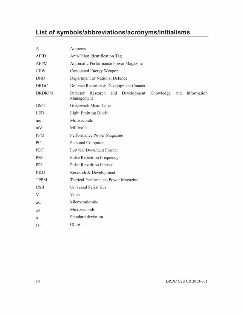
80 DRDC CSS CR 2013-001
List of symbols/abbreviations/acronyms/initialisms
A
AFID
APPM
CEW
DND
Amperes
Anti-Felon Identification Tag
Automatic Performance Power Magazine
Conducted Energy Weapon
Department of National Defence
DRDC Defence Research & Development Canada
DRDKIM Director Research and Development Knowledge and Information Management
GMT
LED
ms
mV
PPM
PC
PRF
PRI
R&D
TPPM
USB
V
C
s
Greenwich Mean Time
Light Emitting Diode
Milliseconds
Millivolts
Performance Power Magazine
Personal Computer
Portable Document Format
Pulse Repetition Frequency
Pulse Repetition Interval
Research & Development
Tactical Performance Power Magazine
Universal Serial Bus
Volts
Microcoulombs
Microseconds
Standard deviation
Ohms

DRDC CSS CR 2013-001 81
Glossary .....
Arc
An electrical spark created between two points.
Arc Phase
The short-duration first part of the electrical pulse generated by the Taser X2 that creates the highest voltage. Required to produce an arc.
Central Limit Theorem
A theorem that states that the mean of a sufficiently large number of independent random variables will be approximately normally distributed.
Firmware
Software that is resident inside the Taser X2 that controls and monitors its operation
Main Phase
The longer-duration, second part of the electrical pulse generated by the Taser X2. It is responsible for inducing neuromuscular incapacitation.
Net Charge
A misleading calculation of charge, in which negative current is subtracted from positive current to obtain a smaller charge value.
Total Charge
The integration of the current magnitude over the time duration of a pulse. Computes the number of charges that moved through a subject.

DRAFT
DOCUMENT CONTROL DATA (Security classification of title, body of abstract and indexing annotation must be entered when the overall document is classified)
1. ORIGINATOR (The name and address of the organization preparing the document. Organizations for whom the document was prepared, e.g. Centre sponsoring a contractor's report, or tasking agency, are entered in section 8.)
Joey Bray Royal Military College
P.O. Box 17000, Station Forces Kingston ON K7K 7B4
2. SECURITY CLASSIFICATION (Overall security classification of the document including special warning terms if applicable.)
UNCLASSIFIED NON CONTROLLED GOODS DMC-A REVIEW: GCEC JUNE 2010
3. TITLE (The complete document title as indicated on the title page. Its classification should be indicated by the appropriate abbreviation (S, C or U) in parentheses after the title.)
4. AUTHORS (last name, followed by initials – ranks, titles, etc. not to be used) Bray, Joey
5. DATE OF PUBLICATION (Month and year of publication of document.)
March 2013
6a. NO. OF PAGES (Total containing information, including Annexes, Appendices, etc.)
81
6b. NO. OF REFS (Total cited in document.)
6 7. DESCRIPTIVE NOTES (The category of the document, e.g. technical report, technical note or memorandum. If appropriate, enter the type of report,
e.g. interim, progress, summary, annual or final. Give the inclusive dates when a specific reporting period is covered.) Contract Report
8. SPONSORING ACTIVITY (The name of the department project office or laboratory sponsoring the research and development – include address.)
9a. PROJECT OR GRANT NO. (If appropriate, the applicable research and development project or grant number under which the document was written. Please specify whether project or grant.)
32bj
9b. CONTRACT NO. (If appropriate, the applicable number under which the document was written.)
10a. ORIGINATOR'S DOCUMENT NUMBER (The official document number by which the document is identified by the originating activity. This number must be unique to this document.)
10b. OTHER DOCUMENT NO(s). (Any other numbers which may be assigned this document either by the originator or by the sponsor.) DRDC CSS CR 2013-001
11. DOCUMENT AVAILABILITY (Any limitations on further dissemination of the document, other than those imposed by security classification.)
Unlimited
12. DOCUMENT ANNOUNCEMENT (Any limitation to the bibliographic announcement of this document. This will normally correspond to the Document Availability (11). However, where further distribution (beyond the audience specified in (11) is possible, a wider announcement audience may be selected.)) Unlimited
Taser X2 Preliminary Investigation

13. ABSTRACT (A brief and factual summary of the document. It may also appear elsewhere in the body of the document itself. It is highly desirable that the abstract of classified documents be unclassified. Each paragraph of the abstract shall begin with an indication of the security classification of the information in the paragraph (unless the document itself is unclassified) represented as (S), (C), (R), or (U). It is not necessary to include here abstracts in both official languages unless the text is bilingual.)
This document describes the physical properties and explains the principles of operation of theTaser X2 conducted energy weapon produced by Taser International. The document alsodescribes hardware and software accessories associated with the weapon. The measuredelectrical conducted waveforms of an Taser X2 are also documented herein, as are a number oftechnical observations regarding the operation of the Taser X2. Conclusions andrecommendations are provided.
Ce document décrit les propriétés physiques et explique les principes de fonctionnement del'arme à impulsions modèle Taser X2 produit par Taser International. Le document décrit aussiles accessoires matérielles et logicielles associées à l'arme. Les mesures électriques des ondesmenées d'un Taser X2 sont également documentées ici, ainsi que certaines observationstechniques concernant le fonctionnement du Taser X2. Des conclusions et des recommandationssont présentées.
14. KEYWORDS, DESCRIPTORS or IDENTIFIERS (Technically meaningful terms or short phrases that characterize a document and could be helpful in cataloguing the document. They should be selected so that no security classification is required. Identifiers, such as equipment model designation, trade name, military project code name, geographic location may also be included. If possible keywords should be selected from a published thesaurus, e.g. Thesaurus of Engineering and Scientific Terms (TEST) and that thesaurus identified. If it is not possible to select indexing terms which are Unclassified, the classification of each should be indicated as with the title.) Tasers; Less Lethal Weapons; Conducted Energy Devices; Taser X2