Embed Size (px)
Citation preview

Tar removal from low-temperature gasifiers
Robin Zwart (ECN)
Simon van der Heijden & Rob Emmen (Dahlman)
Jens Dall Bentzen (Dall Energy)
Jesper Ahrenfeldt (Risø DTU)
Peder Stoholm (DFBT)
Jørn Krogh (Anhydro)
ECN-E--10-008 APRIL 2010

Acknowledgement/Preface This report is prepared within the framework of the ERA-NET Bioenergy project “Tar removal from low-temperature gasifiers”. The project was carried out by ECN and Dahlman from the Netherlands and Dall Energy, Risø DTU, DFBT and Anhydro from Denmark. Gratitude goes to the ERA-NET Bioenergy consortium and in particular SenterNovem and Energinet.dk for supporting this project. SenterNovem became part of Agentschap NL at the beginning of 2010 and is an agency of the Dutch Ministry of Economic Affairs and coordinates the so-called Energy Research Strategy (EOS) program out of which this project was partially financed. The Danish transmission system operator Energinet.dk is an authority under the Danish Ministry of Climate and Energy. Energinet.dk administers the Public Service Obligation Programme (PSO) in terms of the Forskel and the ForskVE programmes. Abstract Biomass is considered an important source of renewable energy needed to realise national and European renewable energy goals and goals for CO2 reduction. Biomass gasification as a technology is recognized generally as highly desirable because of its high efficiency towards all kind of energy products. Biomass can be gasified using many different technologies ranging from high-temperature processes as high as 1500°C to low-temperature processes as low as 500°C. The project “tar removal from low-temperature gasifiers” focuses at gasification processes below 800°C. These so-called low-temperature biomass gasification processes have certain advantages, i.e. they are suitable for fuels with low ash melting points, have a high cold gas efficiency and low tar dew point, require easier gas cooling and cleaning, provide longer residence times, and are associated with less heat transfer limitations within gasifier compared to gasifiers operated at 800 to 900°C. For some applications the main disadvantage of low-temperature gasification is the relatively high tar level in the gas. This is why these processes generally are not considered being suitable for connection to gas engines, gas turbines, fuel cells or catalytic synthesis reactors. All the advantages mentioned above however, urge researchers to develop gas cleaning systems that can extend the application of low-temperature gasifiers from simple co-firing to also the mentioned applications. Being able to handle tars in the 700-800°C interval would be very attractive. This temperature is high enough to have limited tar yield and low enough to have an acceptable tar dew point. In the project, two gas cleaning technologies are adapted and tested in connection to low-temperature gasification, i.e. (i) the OLGA tar removal technology developed by the Dutch partners in the project and (ii) the cooling, filtration and partial oxidation developed by the Danish partners in the project. The project aims at judging technical and economical suitability of these up-scalable tar removal methods connected to high-efficiency low-temperature gasification. Suitability opens the way to high efficient and high fuel flexible biomass gasification systems for the connection to gas engines, gas turbines, fuel cells or catalytic synthesis gas reactors. It is concluded that lowering the gasification temperature will require some modifications of the OLGA technology, though it is expected OLGA can remove also tars from the product gas of a gasifier operated at temperatures below 650°C to low enough levels that a gas engine should run, based on tars. For dust removal, bag house filters are suitable when operated above the tar dew point of the gas. If this would require too high temperatures technically or economically feasible for filters, the OLGA could be applied in which dust can be removed at a temperature below the original tar dew point of the gas. The cooling of gasification is a challenge as long as dust and tars result in fouling in shell and tube heat exchangers. To overcome such problems so called “evaporative coolers” can be used where the evaporative energy of water (or some other liquid) is used to cool the gas.
2 ECN-E--10-008
Contents
List of tables 5 List of figures 5 Summary 7 1. Introduction 11
1.1 Background 11 1.2 Problem definition 11 1.3 Objective 11 1.4 Approach 12 1.5 Reading instructions 12
2. Low-temperature gasification 13 2.1 Indirect air/steam-blown MILENA gasification 13
2.1.1 Description of MILENA 13 2.1.2 Applied operating conditions 14 2.1.3 Experimental results 15
2.2 Direct air-blown WOB gasification 18 2.2.1 Description of WOB 18 2.2.2 Applied operating conditions 18 2.2.3 Experimental results 19
2.3 Direct air-blown LT-CFB gasification 22 2.3.1 Applied operating conditions 24 2.3.2 Experimental results 25
3. Oil based gas washing (OLGA) 29 3.1 Description of OLGA 29 3.2 Required modifications for low-temperature gasification 31
3.2.1 The cooling section: the gas cooler and OLGA collector 31 3.2.2 The oil handling: the oil recovery system (ORS) 32 3.2.3 The tar removal: the OLGA absorber and stripper 33
3.3 Experimental results 34 3.3.1 OLGA micro scale 34 3.3.2 OLGA lab scale 35 3.3.3 OLGA pilot scale 37 3.3.4 ORS lab scale 38 3.3.5 ORS pilot scale 39
3.4 Integration of OLGA and LT-CFB 41 3.4.1 Available process input data 41 3.4.2 Theoretical process design 43 3.4.3 Remarks on the design 45
4. Filtration and partial oxidation 47 4.1 Purpose and Background 47
4.1.1 Bag House Filtration 47 4.1.2 Partial Oxidation 47
4.2 Description of the filtration and partial oxidation set-up 49 4.2.1 Gas cooling prior to bag house filtration 49 4.2.2 Bag House Filtration 51 4.2.3 Partial Oxidation 52
4.3 Experimental results 55 4.3.1 Gas Cooling 55 4.3.2 Filtration 56 4.3.3 Partial Oxidation 57
ECN-E--10-008 3

5. System assessment 61 5.1 MILENA-OLGA based combined heat & power system 61 5.2 LT-CFB with gas cooling and cleaning 62 5.3 Implementation barriers 63
5.3.1 General bioenergy barriers 64 5.3.2 Specific barriers to gasification and gas cleaning 65
6. Conclusions and recommendations 67 Abbreviations and definitions 69 References 71
4 ECN-E--10-008

List of tables
Table 2.1 MILENA lab scale gas composition ....................................................................... 15 Table 2.2 MILENA lab scale tar concentration normalised to 0% N2 ................................... 16 Table 2.3 WOB lab scale operating conditions ...................................................................... 19 Table 2.4 WOB lab scale main gas composition for beech wood / PE................................... 20 Table 2.5 WOB lab scale ash composition for beech wood / PE............................................ 21 Table 2.6 All of the present 8 test with the new 100 kWth LT-CFB plant .............................. 24 Table 2.7 Data for fuels use in 100 kW LT-CFB tests nos. 3-8 .............................................. 24 Table 3.1 LT-CFB 100 kWth feedstock data............................................................................ 41 Table 3.2 LT-CFB 100 kWth fuel composition ........................................................................ 41 Table 3.3 LT-CFB 100 kWth raw product gas composition (outlet gasifier) .......................... 41 Table 3.4 LT-CFB 100 kWth stripper / gasifier air or steam .................................................. 41 Table 3.5 LT-CFB 100 kWth product gas at inlet OLGA ........................................................ 42 Table 3.6 LT-CFB 100 kWth solid particles at inlet OLGA .................................................... 42 Table 3.7 LT-CFB 100 kWth tar data (simplified) at inlet OLGA ........................................... 42 Table 3.8 LT-CFB 100 kWth tar data (composition) at inlet OLGA ....................................... 42 Table 3.9 LT-CFB 100 kWth inorganic impurities data at inlet OLGA .................................. 42 Table 3.10 LT-CFB 100 kWth gas flow ranges ......................................................................... 43 Table 3.11 LT-CFB 100 kWth water dew point gas................................................................... 44 Table 5.1 MILENA 10 MWth design parameters..................................................................... 61
List of figures
Figure 1.1 Scope of project ...................................................................................................... 12 Figure 1.2 Effect of temperature on tar yield & dew point ...................................................... 12 Figure 2.1 MILENA scheme ..................................................................................................... 14 Figure 2.2 MILENA lab & pilot facility ................................................................................... 14 Figure 2.3 MILENA lab scale tar composition for beech wood & sand .................................. 16 Figure 2.4 MILENA lab scale tar composition for beech wood & olivine............................... 16 Figure 2.5 MILENA pilot scale tar composition for clean wood pellets & olivine (air on
riser) ....................................................................................................................... 17 Figure 2.6 Relation between tar dew point and concentration ................................................ 17 Figure 2.7 WOB scheme........................................................................................................... 18 Figure 2.8 WOB lab facility with HGF .................................................................................... 18 Figure 2.9 WOB lab scale tar composition for RDF and for beech wood / PE (bulk)............. 19 Figure 2.10 WOB lab scale tar composition for RDF and for beech wood / PE (detailed)....... 19 Figure 2.11 WOB lab scale elemental composition of ashes for beech wood / PE.................... 21 Figure 2.12 LT-CFB flow diagram (simple version with a hot 2nd cyclone for gas cleaning) ... 22 Figure 2.13 500 kWth LT-CFB test plant at DTU ....................................................................... 23 Figure 2.14 100 kWth LT-CFB gasifier....................................................................................... 23 Figure 2.15 Important process temperatures from 100 kWth LT-CFB test no. 5........................ 26 Figure 2.16 Important process temperatures from 100 kWth LT-CFB test no. 6........................ 26 Figure 2.17 Important process temperatures from 100 kWth LT-CFB test no. 8........................ 26 Figure 2.18 Important process temperatures from last 6 hours of 100 kWth LT-CFB test no. 8 27 Figure 3.1 OLGA equipment selection based on dew points ................................................... 29 Figure 3.2 OLGA scheme ......................................................................................................... 30 Figure 3.3 OLGA lab & pilot facility ....................................................................................... 30 Figure 3.4 OLGA pilot scale modifications ............................................................................. 31 Figure 3.5 ORS scheme ............................................................................................................ 32
ECN-E--10-008 5

Figure 3.6 ORS lab & pilot facility .......................................................................................... 32 Figure 3.7 OLGA micro scale facility ...................................................................................... 33 Figure 3.8 OLGA micro scale with RME scrubber .................................................................. 34 Figure 3.9 OLGA micro scale with biodiesel scrubber ............................................................ 34 Figure 3.10 OLGA micro scale with glycerol scrubber ............................................................. 34 Figure 3.11 OLGA performance downstream RDF gasification at 750 & 850°C ..................... 35 Figure 3.12 OLGA performance downstream beech wood / PE gasification at 550 & 650°C .. 36 Figure 3.13 OLGA performance downstream beech wood / PE gasification at 780 & 850°C .. 36 Figure 3.14 OLGA pilot scale temperature profile .................................................................... 37 Figure 3.15 OLGA pilot scale performance downstream the MILENA gasifier ........................ 38 Figure 3.16 ORS lab scale products........................................................................................... 38 Figure 3.17 ORS lab scale separation of thermoplast from collector oil................................... 38 Figure 3.18 ORS pilot scale effect of dust/tar ratio on oil viscosity........................................... 39 Figure 3.19 ORS pilot scale recovery yield of the light fraction at 320ºC ................................. 40 Figure 3.20 LT-CFB 100 kWth basic OLGA working principle.................................................. 44 Figure 4.1 Results from partial oxidation experiments ............................................................ 48 Figure 4.2 Yields of naphthalene, phenanthrene and anthracene (left) as well as pyrene,
benzanthracene and chrysene (right) as function of the excess air ratio ............... 48 Figure 4.3 CFD simulation of evaporative cooler for the 100 kWth LT CFB gasifier.............. 50 Figure 4.4 Test of nozzle (left), evaporative cooler without insulation (centre) and
evaporative cooler with insulation (right) .............................................................. 50 Figure 4.5 Diagram of the filtration set-up .............................................................................. 51 Figure 4.6 Bag house filter ....................................................................................................... 51 Figure 4.7 Diagram of the gas cleaning set-up ........................................................................ 52 Figure 4.8 Schematic drawing of the partial oxidation reactor ............................................... 52 Figure 4.9 The Petersen Column setup .................................................................................... 53 Figure 4.10 Partial oxidation (POX) and tar sampling setup .................................................... 53 Figure 4.11 Stable isotope dilution illustrated by the analysis of naphthalene.......................... 54 Figure 4.12 Work-up and stable isotope dilution illustrated by the analysis of naphthalene .... 54 Figure 4.13 Gas cooler temperatures from tests during gasifier operation on pectin residues. 55 Figure 4.14 Inside view of the cooler after operation ................................................................ 56 Figure 4.15 Ash & sand particles collected from the bottom of the gas cooler ......................... 56 Figure 4.16 Measurement of pressure drop across back house filter on September 24th 2009.. 56 Figure 4.17 Measurement of pressure drop across back house filter on November 18th 2009 .. 57 Figure 4.18 Picture of an unused bag and a bag after the filtration experiments ..................... 57 Figure 4.19 The POX temperatures during the experiments ...................................................... 58 Figure 4.20 Gas composition of producer gas leaving the POX ................................................ 59 Figure 4.21 Overall tar content of producer gas leaving the POX reactor ............................... 59 Figure 4.22 PAH-tar content of producer gas leaving the POX reactor.................................... 60 Figure 5.1 MILENA 10 MWth tar removal efficiency for different gasification temperatures . 62 Figure 5.2 Principal diagram of Low Temperature gasifier with gas cooling and gas filter .. 62 Figure 5.3 Compact cooler design for gas coolers below 10 MWth (left) and cooling tower
design for gas coolers above 10 MWth (right) ........................................................ 63
6 ECN-E--10-008

Summary
In the project “tar removal from low-temperature gasifiers” two gas cleaning technologies are adapted and tested in connection to low-temperature gasification. These concern the OLGA tar removal technology developed by the Dutch partners in the project and the cooling, filtration and partial oxidation developed by the Danish partners in the project. This project aimed at judging the technical and economical suitability of two up-scalable tar removal methods (OLGA and Partial Oxidation) connected to high-efficiency low-temperature gasification. Suitability opens the way to high efficient and high fuel flexible biomass gasification systems for the connection to gas engines, gas turbines, fuel cells or catalytic synthesis gas reactors.
Low temperature gasification In this project, low-temperature gasification refers to 800°C or below. Fluidized bed reactors operated at 800°C or below usually show poor carbon conversion resulting in both low efficiency and waste problems (carbon containing ash). By using the technology of coupled reactors, both Danish and Dutch researchers succeeded in combining low-temperature gasification with high carbon conversion. The Danish concept called Low-Temperature Circulating Fluidized Bed (LT-CFB) uses a second coupled reactor called “char reaction chamber” where char from fast pyrolysis is converted at low temperature (typically 750°C) due to the high residence time. The Dutch indirect MILENA gasification concept uses a second coupled reactor where air is introduced to burn the remaining char. From the tar composition at different gasification temperatures it can clearly be observed that oxygen containing phenolic model compounds such as phenol, cresol and naphthols are significantly converted when the temperature is increased from 750°C to temperatures above 850°C. Non-oxygen containing aromatic or polyaromatic model compounds, however, are not reduced that significantly or are even increasing in content with increasing temperature. This can be explained by the fact that biomass tars are made up from a wide variety of compounds. The most reactive compounds containing heteroatoms like N and O and/or pendant groups react first, with the result that the remaining tars end up with a different composition. Ultimately, to convert the last tars (the polycyclic aromatic hydrocarbons) always present in biomass tars cracking needs to take place at the temperatures required to crack naphthalene, phenanthrene, and anthracene and would require higher temperatures, typically between 850 and 1200°C. At lower temperatures, 550 and 650°C, the amount of conventional non-polar tars are relatively low, while the polar tars as well as tars undetectable by gas chromatography dominate the tar spectrum. The trend in the main gas composition is the increase of the unsaturated hydrocarbons acetylene and ethylene, as well as benzene and methane with increasing gasification temperature from 550 to 850°C. The increase of the first three is probably caused by cracking of more heavy polar tars at higher temperature, whereas the increase of methane might be affected more by some methanation related reactions. One can however expect a decrease of these components when the temperature is increased further. Concerning ash, the cyclone ashes for gasification at over 750°C have a significant higher ash content compared to the ash for gasification at 550°C. The latter contain far more carbon due to the limited carbon conversion during gasification at lower temperature. At higher temperatures, more chlorine ends up in the cyclone ash.
ECN-E--10-008 7

Oil based gas washing (OLGA) The OLGA not only removes tars, but also dust as well as contaminants like thiophenes and dioxins from the product gas of a (biomass) gasifier. Although originally designed for tar removal downstream gasifiers operated at 800-900°C, the OLGA technology has been tested downstream gasifiers operated at lower temperatures as well, showing that OLGA is not limited to gasifiers operated at 800-900°C. At lower temperatures, the tar composition shifts from large multiple ring tar components with high dew points to smaller single or double ring tar components with lower dew points. Furthermore, the tar composition will shift from rather stable non-polar components towards reactive polar components. As OLGA was originally designed to remove mainly non-polar tars, application of OLGA downstream gasifiers operated at lower temperatures will require some modifications. The key issues refer to tar polymerisation, oil stability and viscosity, aerosol formation and capture, and overall performance of the tar removal technology. As such, the cooling section between gasifier and OLGA requires some specific attention. Although the dew point of the tars formed is lower, the amount of tars is significantly higher and in particular for an indirect gasifier like the MILENA. More importantly, the tars are much less stable; hence the risk of tar polymerization is significantly higher. As this polymerization is strongly depending on temperature and residence time, one should avoid condensation as far as possible and after condensation reduce the temperature as quickly as possible. As such, the cooling capacity of the OLGA collector has to be increased slightly in order to cope with the higher inlet temperature of the gas to OLGA. The oil stability and viscosity, controlled by the ORS, depend on the amount and composition of the tars as well as the amount of fine solids entering the OLGA. In order to be able to pump this liquid product, the amount of fine solids and the amount of (heavy) tars should be in the right proportion. At the same time, all fine solids will be present at a certain stage in the collector oil loop, and hence influence the viscosity of this oil. Although the content of fine solids in the product gas of a low temperature gasifier is not that different from a gasifier operated at higher temperatures, the recovery yield of the ORS will have to be optimised in a complete different way for a low temperature gasifier, due to the reduction of in particular the amount of heavy tars formed in the gasifier. The more heavy tars or dust are present in the gas, the higher the recovery yield for light tars of the ORS will have to be in order to control the viscosity. The target for this optimisation is having a viscosity of 100 cP or lower, which means that in the collector oil loop a dust concentration of 5 to 10% is acceptable, whereas for the (heavy) tar fraction obtained from the ORS this dust fraction can be significantly higher. At low temperature gasification the tar composition will shift from rather stable non-polar components towards highly reactive polar components. As OLGA was originally designed to remove mainly non-polar tars, application of OLGA downstream gasifiers operated at lower temperatures will also require some modifications in the absorber stripper section of the OLGA. These modifications mainly focus on changing the conventional absorption oil applied in OLGA or implementing another oil absorption step supplementary to the existing one. As long as the temperature of the gasification is in a range of 750 to 850°C, there is no real need to change oils or add columns. When the gasification temperature is 650°C or even lower, the tar slip of an OLGA with conventional oils will be too high, and (additional) gas scrubbing with a different oil will be required to maintain the same tar removal efficiency. This (additional) oil for low-temperature gasifiers can be glycerol (preferred above RME and biodiesel), however can also be some form of polar tar condensate.
8 ECN-E--10-008

Filtration and partial oxidation The purpose of this study is to prove that it is possible to filter the gas from a LT CFB gasifier in a commercially available bag house filter at temperatures around 300 °C. The traditional way to clean the gas from the LT-CFB gasifier includes only cyclones. This approach leaves a considerable amount of particles in the gas, and thereby limits the potential usage. If the last particles were removed the gas could be used for multiple additional purposes in gas boilers, and other equipment that does not tolerate particles. Previous studies have shown that the tar dew point of gas from the LT-CFB gasifier is somewhere between 190 and 250 °C. As it is possible to purchase affordable and commercially available bag house filters that functions in temperatures as high as 370 °C, it seemed reasonable to conduct the filter experiments with gas temperatures above the tar dew point. At these temperatures clogging of the bag house filters by liquid tars is avoided. The study also focuses on the reduction of tars via partial oxidation. The producer gas leaving a biomass gasifier normally contains more or less tar depending on the design of the gasifier and the type of biomass used as fuel. The partial oxidation of the gas results in a significantly reduction of the tar. Primary and secondary tars are oxidized or converted to tertiary tars during this partial oxidation. The partial oxidation of the pyrolysis gas can be recognized as one of the main reasons for the almost “tar-free” producer gas from a staged gasifier.
System assessment In order to determine the effect of the gasification temperature on the design of the tar removal several systems are assessed. For MILENA and OLGA, a predesign is made of the OLGA for a 10 MWth combined heat and power plant. For the comparison, gasification temperatures are chosen, at which it is expected that the OLGA will not require an additional column for the removal of specific polar components. Decreasing the gasification temperature does not have an immediate effect on the required column heights, as it is still possible to have a sufficient tar removal by increasing the amount of absorption oil. Lowering the gasification temperature from approximately 880 to 775°C would require approximately 20% additional oil in the absorber loop, corresponding to an increase of the diameter of the absorber and stripper column with less than 5%. It therefore can be concluded that lowering the gasification temperature in the MILENA has not a large influence on the design of the columns in OLGA, hence the capital costs. The temperature decrease in the gasifier however already broadens the choice of biomass feedstock significantly, allowing also the application of a feedstock with an ash melting temperatures around 800°C. When the gasification temperature is decreased further to below 650°C, something that might be necessary to apply feedstock’s like straw and grass with much lower ash melting points, the need for an additional scrubbing column will increase the costs of the OLGA. In general though, the increased capital costs will be compensated by the lower costs of the feedstock and the increased overall efficiency when operating at lower temperatures. Based on the successful tests of cooling the gas and particle filtration it seams very likely that also a robust gas cooling and cleaning system can be implemented for a LT-CFB gasifier. Besides the OLGA mentioned above, different designs of evaporative coolers can be applied. For smaller plants (below 10 MWth) the Danish design used in the current project is recommended. This is a compact design: The cooler is below 6 m tall. However for larger volumes than 10 MW one shall then consider to use a cooling tower design, where the hot gas enters from the top and water is sprayed into the gas from the side. The evaporative cooling principle is especially and advantage if low temperature heat (district heat) is to be generated, as the energy used for cooling the gas is recovered in a condensing flue gas unit.
ECN-E--10-008 9

10 ECN-E--10-008

ECN-E--10-008 11
1. Introduction
1.1 Background Biomass is considered an important source of renewable energy needed to realise national and European renewable energy goals and goals for CO2 reduction. Biomass gasification as a technology is recognized generally as highly desirable because of its high efficiency towards all kind of energy products. Biomass can be gasified using many different technologies ranging from high-temperature processes as high as 1500°C to low-temperature processes as low as 500°C. This project focuses at gasification processes below 800°C. These so-called low-temperature biomass gasification processes have following advantages:
Suitable for (generally cheap) fuels with low ash melting points; High cold gas efficiency due to less heat loss and less energy demand for heating; Low tar dew point 1 resulting in less cooling and fouling problems compared to
“traditional” fluidized bed gasifiers at typically 850-950°C; Easier gas cooling and cleaning due to small content off vaporized ash components
present in the raw gas; For some processes longer residence times due to lower reaction rates, resulting in less
stringent specifications of fuel composition/homogeneity and on fuel feeding; Less heat transfer limitations within gasifier enabling operation at elevated pressure.
1.2 Problem definition The main disadvantage of low-temperature gasification is the relatively high tar level in the gas. This is why these processes generally are not considered being suitable for connection to gas engines, gas turbines, fuel cells or catalytic synthesis reactors. All the advantages mentioned previously however, urge researchers to develop gas cleaning systems that can handle the higher tar content and as such can extend the application of low-temperature gasifiers from simple co-firing to also the mentioned applications.
1.3 Objective In this project, two gas cleaning technologies are adapted and tested in connection to low-temperature gasification. These concern (1) OLGA and (2) cooling, filtration and partial oxidation. Figure 1.1 schematically shows the scope of the project. This project aimed at judging the technical and economical suitability of two up-scalable tar removal methods (OLGA and Partial Oxidation) connected to high-efficiency low-temperature gasification. Suitability opens the way to high efficient and high fuel flexible biomass gasification systems for the connection to gas engines, gas turbines, fuel cells or catalytic synthesis gas reactors. Figure 1.2 shows different gasification temperature regions on the basis of tar dew point and tar yield. Being able to handle tars in the 700-800°C interval would be very attractive. This temperature is high enough to have limited tar yield and low enough to have an acceptable tar dew point.
1 The tar dew point is the temperature at which tars start condensing upon cooling the gas. Low-temperature tars are
not similar to the high-temperature tars. High-temperature tars contain high amounts of poly-aromatic hydrocarbons that have high boiling points (condensation at high temperature). Low-temperature tars contain much smaller molecules, often including hetero-atoms (highly water soluble compounds). This means that tar dew points are much lower.

biomass
low-temperature gasification (<800°C)
high tar gas high efficiency
OLGA partial oxidation
low tar gas high efficiency
further gas cleaning
gas utilization (SNG, SOFC, FT, DME, …)
this
pro
ject
Figure 1.1 Scope of project
Figure 1.2 Effect of temperature on tar yield & dew point
1.4 Approach This project includes six participants relevant in the field of low-temperature gasification and/or gas cleaning, more specifically tar removal. Two participants are from the Netherlands and mainly focus on MILENA gasification and OLGA gas cleaning (ECN and Dahlman) and four participants are from Denmark (Dall Energy, Risø DTU, DFBT and Anhydro) and mainly focus on LT-CFB gasification and cooling, filtration and partial oxidation. Within the project, three work packages (WP) are defined. WP1 has the objective to have OLGA successfully remove tars from low-temperature gasification, WP2 has the objective to verify that particles after low-temperature gasification can be filtered in a bag filter and that the tar content can be reduced considerably by partial oxidation and WP3 has the objective to assess the systems based on low-temperature gasification and quantify the advantages over similar more “traditional” systems. By having both Dutch and Danish partners participating in all three work packages and determine process operating conditions the originally separately developed gas cleaning technologies can be adapted and tested in connection to both the also originally separately developed gasification technologies.
1.5 Reading instructions The structure of this report is as follows:
Chapter 2 describes the applied gasification concepts as well as the obtained results by both the Dutch and the Danish partners;
Chapter 3 describes the oil based gas washing concept applied by the Dutch partners as well as the modifications required and the results obtained downstream low-temperature gasification processes;
Chapter 4 describes the gas filtration and partial oxidation concept applied by the Danish partners as well as the modifications required and the results obtained downstream low-temperature gasification processes;
Chapter 5 provides a system assessment of the different gas cleaning technologies downstream the different gasification concepts;
Chapter 6 summarises the conclusions and recommendations of this study.
12 ECN-E--10-008

2. Low-temperature gasification
In this project, low-temperature gasification refers to 800°C or below. Fluidized bed reactors operated at 800°C or below usually show poor carbon conversion resulting in both low efficiency and waste problems (carbon containing ash). By using the technology of coupled reactors, both Danish and Dutch researchers succeeded in combining low-temperature gasification with high carbon conversion. The Danish concept called Low-Temperature Circulating Fluidized Bed (LT-CFB) uses a second coupled reactor called “char reaction chamber” where char from fast pyrolysis is converted at low temperature (typically 750°C) due to the high residence time. The Dutch indirect MILENA gasification concept uses a second coupled reactor where air is introduced to burn the remaining char. The technologies as well as the applied operating conditions and the results obtained are described in this chapter. Besides the MILENA and LT-CFB gasification technologies, also results with the bubbling fluidized bed gasifier WOB are presented. The WOB gasifier has been applied by ECN as this facility offered also the opportunity to be operated stable at temperatures of 650°C and lower.
2.1 Indirect air/steam-blown MILENA gasification The first design of the MILENA gasifier was made in 1999. The first cold flow, for hydrodynamic testing, was built in 2000. Financing a lab-scale installation appeared to be problematic, because there was no interest in a new gasification technology at that time. This changed when Substitute Natural Gas (SNG) was identified as a promising bio-fuel and the indirect MILENA gasification process was identified as a promising technology for the production of SNG [1]. The construction of a 30 kWth MILENA installation (Figure 2.2 on the left) was started in 2003. The installation was finished and taken into operation in 2004. Financing of the 800 kWth MILENA pilot plant (Figure 2.2 on the right) was approved in 2006 and the construction was finished in 2008 [2].
2.1.1 Description of MILENA The MILENA gasifier contains separate sections for gasification and combustion. Figure 2.1 shows a simplified scheme of the MILENA process. The gasification section consists of three parts, i.e. the riser (1), the settling chamber (2) and the downcomer (3). The combustion section contains three parts, the bubbling fluidized bed combustor (4), the freeboard (5) and the sand transport zone (6). The arrows in Figure 2.1 represent the circulating bed material. The processes in the gasification section will be explained first. Biomass (e.g. wood) is fed into the riser. A small amount of superheated steam is added from below. Hot bed material (in normal operating mode sand or olivine with a temperature of typically 925°C) enters the riser from the combustor through a hole in the riser opposite and just above the biomass feeding point. The bed material heats the biomass to 850°C, converting the biomass particles into gas, tar and char. The volume created by the gas from the biomass results in an increase of the vertical velocity, creating a “turbulent fluidization” regime in the riser and carrying over of the bed material together with the degasified biomass particles (char). The vertical velocity of the gas is reduced in the settling chamber, causing the larger solids (bed material and char) to separate from the gas and fall down into the down comer. The producer gas leaves the reactor from the top and is sent to the cooling and gas cleaning section. Typical residence time of the gas is several seconds.
ECN-E--10-008 13

Gas
ifier
Flue gas
Steam
Air
Producer gas
Tar + dust
Biomass
1
2
3
4
5
6
Figure 2.1 MILENA scheme
Figure 2.2 MILENA lab & pilot facility
The combustor operates as a bubbling fluidized bed (BFB). The downcomer transports bed material and char from the gasification section into the combustor. Tar and dust, separated from the producer gas, are also returned to the combustor. Char, tar and dust are burned with air to heat the bed material. Flue gas leaves the reactor to be cooled, de-dusted and emitted. The heated bed material leaves the bottom of the combustor through a hole into the riser. In normal operation mode, no additional heat input is required; all heat required for the gasification process is produced by the combustion of the char, tar and dust in the combustor. The hot producer gas from the gasifier contains several contaminants, such as dust, tar, chloride and sulphur, which have to be removed before it can be applied in downstream applications like gas engines and turbines or catalytic conversion into for example bio-SNG. Tar compounds condense when the gas is cooled, which makes the gas very difficult to handle, especially in combination with dust. The producer gas is cooled in a heat exchanger, designed to treat gas which contains tar and dust. The heat is used to pre-heat combustion air. Tar and dust are removed from the gas in the downstream OLGA gas cleaning section (described in Chapter 3).
2.1.2 Applied operating conditions Indirect gasifiers like the MILENA theoretically are operated at an equilibrium based on the temperature dependence of the char yield in the gasifier: char yield decreases with temperature. Since this char is combusted to produce the heat, this leads to an equilibrium where char yield matches the energy demand of the gasification [3]. Typically this results in a temperature within the riser of 850°C and within the combustor of 925°C. Lowering the temperature in the riser inevitably results in more remaining char [4], which is send to the combustor, hence increasing the temperature in the combustor. In order to maintain the lower temperature in the riser, as desired in low temperature gasification concepts, some form of cooling is required. On lab scale, this is relatively easy as heat loss from the process is compensated by high temperature electrical trace heating and external insulation. Switching off the electrical trace heating would increase the heat loss on the combustor, hence lowering the equilibrium temperature levels in both the riser and the combustor with roughly 100°C. Alternatively, the biomass supply to the gasifier can be lowered, and the initial moisture content of the biomass or the amount of fluidization gas in the riser can be increased. Tests on lab scale showed that the temperature of within the riser could be lowered to approximately 650°C. Stable operation of the gasifier at lower temperatures could not be achieved unless active cooling would be installed on the combustor wall.
14 ECN-E--10-008

As the gas composition of the lab scale MILENA gasifier operated at these temperatures of 650°C was considered not to be representative for actual commercial low temperature
the pilot lant is to realize an installation which can be used to do experiments under realistic
asifier are based on beech wood as feedstock. Two test catalytically active olivine was applied as bed material and
gasification, tests on MILENA lab scale were only performed at temperatures in the riser between 735 and 880°C. In order to verify the suitability of the OLGA tar removal downstream gasifiers operated at even lower temperature, hence producing significant amounts of polar in stead of non-polar tars, also tests were performed with the lab scale direct air-blown WOB gasifier, which can be operated more easily at lower temperatures (described in §2.2). On pilot scale, no external heat supply to the reactor has been installed, as the goal forpcommercial conditions [2]. This also means an increase in fuel particle size from 1–3 mm for the lab scale installation to < 15 mm for the pilot plant. Like the lab scale facility the pilot plant facility is not equipped with an active cooling on the combustor side. As such, gasification at temperatures in the riser below 750°C can (not yet) be achieved. Different tests are performed within a range of 750 to 880°C, similar to the tests performed with the lab scale MILENA.
2.1.3 Experimental results The tests with the MILENA lab scale gcampaigns were done, one in whichone in which sand was used. The temperature in the riser was varied over 100°C. For the tests with sand as bed material, the lowering of the temperature was achieved mainly by switching off the trace heating. The additional N2 fed to the riser, in order to maintain the same gas velocity in the riser, also contributed to the cooling. The data on the gas composition as presented in Table 2.1, hence have to be corrected for the dilution caused by this N2 (Table 2.2). The same is done for the detailed tar analysis as presented in Figure 2.3 and Figure 2.4. For the pilot scale MILENA, similar data are presented in Figure 2.5. These data are from two representative tests with the MILENA being operated at approximately 800 and 830°C on clean wood pellets, sand as bed material and air on the riser.
Table 2.1 MILENA lab scale gas composition Feedstock Beech wood Beech wood Bed material Olivine Sand
2Temperature [°C] 776 782 832 861 880 882 735 775 819 861 CO [mol%dry] 29.3 30.4 2 27.5 28.4 28.8 1 39.3 9.7 31.4 33.0 37.H 2 [mol%dry] 22.0 21. 27. 10. 13. 17. 21.4 22.8 20.7 3 24.9 7 8 1 4 CO [mol%dry] 23.2 9 24.0 24.2 24.9 24.8 25.5 9.3 10.7 12.0 13.9 CH [mol%dry] 4 10.5 10.8 10.3 10.6 9.5 9.5 9.2 10.9 12.1 12.8 C H [mol%dry] 2 2 0.3 0.3 0.3 0.5 0.2 0.3 0.2 0.3 0.4 0.5 C H [mol%dry] 2 4 4.3 4.6 4.3 4.1 3.4 3.5 3.0 3.8 4.4 4.4 C2H6 [mol%dry] 0.6 0.6 0.3 0.2 0.2 0.1 0.5 0.5 0.4 0.2 C6H6 [Vppmdry] 7343 7885 8851 10 9551 9636 4268 6736 9155 12233 179 C7H8 [Vppmdry] 2006 1907 1468 1088 1635 1846 1513 1303 944 811 N2 [mol%dry] 3.8 4.6 3.4 4.0 3.1 3.6 35.2 24.8 15.5 5.6 Tars 3 Class 2 tars [mg/m ³dry] n 4613 4082 1987 1073 982 486 4472 4932 3680 1462 Class 3 tars [mg/mn³dry] 209 287 253 299 197 158 404 541 482 275 Class 4 tars [mg/mn³dry] 8405 9521 12071 15049 11406 11689 4816 10334 17391 18579 Class 5 tars [mg/mn³dry] 1088 1352 2004 3222 2147 2289 395 1321 3413 5010 Unknowns [mg/mn³dry] 6118 6796 5094 5307 3642 3052 7240 7923 8258 6556
2 The temperature presented is the temperature within the settling chamber of the MILENA gasifier and is
considered to be the most accurate for describing the actual gasification temperature. 3 The tars are subdivided into five tar classes (more information on the Thersites website http://www.thersites.nl) .
Class 1 tars are GC undetectable tars, including the heaviest tars that condense at high temperature even at very low concentrations. Class 2 tars consist out of heterocyclic components (like phenol, pyridine, cresol) that generally exhibit high water solubility, due to their polarity. Class 3 tars are light aromatic components that are not important in condensation and water solubility issues. Class 4 tars are light polyaromatic hydrocarbons (2-3 rings) that condense at relatively high concentrations and intermediate temperatures. Class 5 tars are heavy polyaromatic hydrocarbons (4-5 rings) that condense at relatively high temperature at low concentrations.
ECN-E--10-008 15

Table 2.2 MILENA lab e on ati rm d N
scal tar c centr on no alise to 0% 2 Feedstock Beech wood Beech wood Bed material Olivine Sand Temperature [°C] 776 782 832 861 880 882 735 775 819 861 CO [mol%dry] 30.5 31.9 3 28.4 29.5 44.4 9 41.6 0.7 32.7 43.9 43.H2 [mol% ] 22.9 22.4 23. .6 28.2 25.8 16.5 18. 20.2 22.7 dry 6 21 4 CO2 [mol%dry] 24.8 25.2 25.1 25.9 25.6 26.5 14.4 14.2 14.2 14.7 CH4 [mol%dry] 10.9 11.3 10.7 11.0 9.8 9.9 14.2 14.5 14.3 13.6 C2H2 [mol%dry] 0.3 0.3 0.3 0.5 0.2 0.3 0.3 0.4 0.5 0.5 C2H4 [mol%dry] 4.5 4.8 4.5 4.3 3.5 3.6 4.6 5.1 5.2 4.7 C2H6 [mol%dry] 0.6 0.6 0.3 0.2 0.2 0.1 0.8 0.7 0.5 0.2 C6H6 [Vppmdry] 7633 8265 9163 10 9857 9996 6586 8957 10 12659 834 901 C7H8 [Vppmdry] 2085 1999 1520 1133 2523 2455 1791 1380 974 841 Tars normalised to 0% N2 Class 2 tars [mg/mn³dry] 4795 4279 2057 1118 1013 504 6901 6559 4355 1549 Class 3 tars [mg/mn³dry] 217 301 262 311 203 164 623 719 570 291 Class 4 tars [mg/mn³dry] 8737 9980 12496 15676 11771 12126 7432 13742 20581 19681 Class 5 tars [mg/mn³dry] 1131 1417 2075 3356 2216 2374 610 1757 4039 5307 Unknowns [mg/mn³dry] 6360 7124 5273 5528 3759 3166 1 1173 1 0536 9773 6945
0
1000
2000
3000
4000
5000
6000
7000
8000
9000
10000
735°C 775°C 819°C
Ben
zeen
SP
ATo
luee
n S
PA
Eth
ylbe
nzee
n S
PA
m/p
-Xyl
een
SP
Ao-
Xyl
een
+ S
tyre
enP
heno
lo-
Cre
sol
Inde
enm
/p-C
reso
lN
afta
leen
Qui
nolin
eIs
oqui
nolin
e2-
met
hyln
afta
leen
1-m
ethy
lnaf
tale
enB
iphe
nyl
Eth
enyl
naph
tale
enA
cena
phty
leen
Ace
naph
teen
Fluo
reen
Phe
nant
hree
nA
nthr
acee
nFl
uora
nthe
enP
yree
nBe
nzo(
a)an
thra
ceen
Chr
ysee
nBe
nzo(
b)flu
oran
thee
Ben
zo(k
)fluo
rant
heen
Ben
zo(e
)pyr
een
Ben
zo(a
)pyr
een
Per
ylee
nIn
deno
(123
-B
enzo
(ghi
)per
ylee
nC
oron
een
Unk
now
ns-1
Unk
now
ns-2
Unk
now
ns-3
Unk
now
ns-4
Unk
now
ns-5
Tar c
onte
nt(m
g/m
n³dr
y at 0
% N
2)
861°C
Figure 2.3 MILENA lab scale tar composition for beech wood & sand
0
1000
2000
3000
4000
5000
6000
7000
8000
9000
10000
776°C 782°C 832°C 861°C 880°C
Ben
zeen
SP
ATo
luee
n S
PA
Eth
ylbe
nzee
n S
PA
m/p
-Xyl
een
SP
Ao-
Xyl
een
+ S
tyre
enP
heno
lo-
Cre
sol
Inde
enm
/p-C
reso
lN
afta
leen
Qui
nolin
eIs
oqui
nolin
e2-
met
hyln
afta
leen
1-m
ethy
lnaf
tale
enB
iphe
nyl
Eth
enyl
naph
tale
enA
cena
phty
leen
Ace
naph
teen
Fluo
reen
Phe
nant
hree
nA
nthr
acee
nFl
uora
nthe
enP
yree
nB
enzo
(a)a
nthr
acee
nC
hrys
een
Ben
zo(b
)fluo
rant
hee
Ben
zo(k
)fluo
rant
heen
Ben
zo(e
)pyr
een
Ben
zo(a
)pyr
een
Per
ylee
nIn
deno
(123
-B
enzo
(ghi
)per
ylee
nC
oron
een
Unk
now
ns-1
Unk
now
ns-2
Unk
now
ns-3
Unk
now
ns-4
Unk
now
ns-5
Tar c
onte
nt(m
g/m
n³dr
y at 0
% N
2)
882°C
Figure 2.4 MILENA lab scale tar composition for beech wood & olivine
16 ECN-E--10-008

ECN-E--10-008 17
0
1000
2000
3000
4000
5000
6000
7000
8000
9000
10000
Ben
zeen
-SP
ATo
luee
n-SP
AEt
hylb
enze
enm
/p-X
ylee
n-S
PA
o-X
ylee
n+St
yree
n S
PA
Phe
nol
Inde
en+o
-cre
sol
m/p
-Cre
sol
Naf
tale
enQ
uino
line
Isoq
uino
line
2-m
ethy
l-naf
tale
en1-
met
hyl-n
afta
leen
Bip
heny
lE
then
yl-n
apht
alee
nA
cena
phty
leen
Ace
naph
teen
Fluo
reen
Phen
anth
reen
Ant
hrac
een
Fluo
rant
heen
Pyre
enB
enzo
(a)-a
nthr
acee
nC
hrys
een
Ben
zo(b
)-flu
oran
thee
nB
enzo
(k)-f
luor
anth
een
Ben
zo(e
)-pyr
een
Ben
zo(a
)-pyr
een
Per
ylee
nIn
deno
(123
-cd)
-D
iben
z(ah
)-ant
hrac
een
Ben
zo(g
hi)-p
eryl
een
Cor
onen
e
Unk
now
ns-1
Unk
now
ns-2
Unk
now
ns-3
Unk
now
ns-4
Unk
now
ns-5
Tar c
onte
nt(m
g/m
n³dr
y at 0
% N
2)
797°C 829°C
Figure 2.5 MILENA pilot scale tar composition for clean wood pellets & olivine (air on riser)
From the tar composition at different gasification temperatures it can clearly be observed that oxygen containing phenolic model compounds such as phenol, cresol and naphthols are significantly converted when the temperature is increased from 750°C to temperatures above 850°C. Non-oxygen containing aromatic or polyaromatic model compounds, however, are not reduced that significantly or are even increasing in content with increasing temperature. This can be explained by the fact that biomass tars are made up from a wide variety of compounds. The most reactive compounds containing heteroatoms like N and O and/or pendant groups react first, with the result that the remaining tars end up with a different composition. Ultimately, to convert the last tars (the polycyclic aromatic hydrocarbons) always present in biomass tars cracking needs to take place at the temperatures required to crack naphthalene, phenanthrene, and anthracene and would require higher temperatures, typically between 850 and 1200°C [5].
Figure 2.6 Relation between tar dew
Looking at the effect of temperature on the
The effect of and composition on OLGA is discussed in more detail
different classified tars (Table 2.2), a trend can be observed that the content of class 2 tars significantly decreases when the temperature is increased from 700 to 850°C, class 3 tars are relatively stable in this temperature area and that the content of class 4 and 5 tars in the gas initially increases (till a temperature of approximately 860°C) before decreasing at higher temperatures. Considering this trend and the tar dew points of the specific tar classes (as presented in Figure 2.6 [6]), the bell shaped curve of the tar dew point as presented in Figure 1.2 can easily be explained. point and concentration
the changing tar quantities in Chapter 3. Due to the limitations in operating temperatures of both the lab and pilot scale MILENA gasifiers, no research was performed on indirect gasification at temperatures below 735°C and the effect this would have on tar formation. Results of direct gasification at temperatures even below 700°C are however reported in §2.2 on lab scale WOB gasification as well as §3.2.3 on micro scale OLGA experiments.

2.2 Direct air-blown WOB gasification The “biomass fluidized bed research facility” WOB is the oldest fluidized bed test facility within the current lab-scale test park at ECN. The WOB has been used for the gasification of many different fuels and mixtures, but has also been proven to be suitable for both the pyrolysis and combustion of these fuels and mixtures. Among the fuels tested are wood, straw, RDF and manure. Like with the MILENA gasifier, the WOB gasifier is connected to almost all lab facilities available and hence extensively used as a fuel gas generator for research on downstream gas cleaning and conditioning equipment.
2.2.1 Description of WOB The WOB gasifier is an atmospheric bubbling fluidized bed gasifier with a feedstock capacity of approximately 1 kg/h. The gasifier is electrically heated and has an internal diameter of 74 mm in the bubbling fluidized bed section, increasing to 108 mm in the freeboard section at a height of 500 mm (Figure 2.7). The total length is 1100 mm from the metal distributor plate to the product gas outlet. In the product gas outlet a small cyclone is positioned for removal of the bulk of the ash leaving the gasifier. Downstream this cyclone, a hot gas filter (HGF, Figure 2.8) and the lab scale OLGA facility (Chapter 3, Figure 3.3) are installed.
Figure 2.7 WOB scheme
Figure 2.8 WOB lab facility with HGF
Although the WOB has been used for pyrolysis, gasification and combustion, operation at low temperatures has a certain drawback. At low temperature, whether it is pyrolysis or gasification, the biomass is not fully converted. As a result unconverted char will accumulate in the bed, causing an increase of the bed as it is not possible to drain the bed during operation of the WOB. Furthermore, the char might act as catalyst for tar cracking reactions, resulting for long test runs in different tar compositions for the lab scale WOB compared to a commercial BFB.
2.2.2 Applied operating conditions The tests with the WOB operated as low temperature gasifier were originally scheduled to be based on the application of refuse derived fuel (RDF). Feeding this feedstock to the WOB had been done already in previous experiments [7], and the RDF is considered to be an interesting fuel for low temperature gasification as specific contaminants present in the (waste stream) RDF would not end up in the product gas. Due to some chlorine and plastics related issues briefly discussed later on (§3.3), it became difficult to perform an extensive testing campaign on RDF and it was decided to operate the gasifier on a mixture of beech wood and polyethylene (PE). This mixture resembles RDF, without having a large amount of chlorine present in the gas. As such it provided the necessary information for low temperature gasification and tar removal, while avoiding the chlorine issues observed during gasification of RDF. Table 2.3 summarises the applied operating conditions of the low temperature gasification tests that will be discussed in this report.
18 ECN-E--10-008

Table 2.3 WOB lab scale operating conditions
Abbreviation Feedstock WOB temperature Remarks RDF-750 RDF 750°C Only OLGA collector applied downstream RDF-850 RDF 850°C Only OLGA collector applied downstream BWPE-550 Beech wood + 10 wt.% PE 550°C Complete OLGA applied downstream BWPE-650 Beech wood + 10 wt.% PE 650°C Complete OLGA applied downstream BWPE-780 Beech wood + 10 wt.% PE 780°C Complete OLGA applied downstream BWPE-850 Beech wood + 10 wt.% PE 850°C Complete OLGA applied downstream
In all tests, the WOB was operated on air and steam, while applying (non-catalytic) sand as bed material. The hot gas filter, applied in all tests, was operated on a temperature level of 450°C and coated with kaolin. The kaolin is not expected to be catalytically active for tar cracking.
2.2.3 Experimental results 2.2.3.1 Tar composition In Figure 2.9 the tar composition of the (N2 rich) product gas is presented for the tests with wood and PE as well as with RDF. As the RDF contains significant amounts of polystyrene (in the form of Styrofoam), this graph is dominated by the styrene peak. In Figure 2.10, therefore, the same composition is presented while limiting the range of the tar content scale.
Figure 2.9 WOB lab scale tar composition for RDF and for beech wood / PE (bulk)
Figure 2.10 WOB lab scale tar composition for RDF and for beech wood / PE (detailed)
ECN-E--10-008 19

For the RDF gasification at 750 and 850°C, besides the specific styrene peak, a similar trend can be observed as with the beech wood gasification tests with MILENA; phenol levels decrease with increasing temperature, whereas naphthalene (and associated components like acenaphthylene and phenanthrene) increase. Also the behaviour of the tars classified as unknowns is similar. And although the total tar concentration due to the gasification of the (waste stream) RDF increased significantly, taking into account that the data presented are not corrected for the nitrogen content, the absolute levels are not a priori causing concerns for the performance of OLGA downstream this RDF gasification (as will be shown in §3.3). The RDF tests encountered condensation though of an unusual thermoplast in the temperature area of 150 to 200°C. Although the thermoplast softens and melts upon heating similar to tars, its liquid viscosity is much higher compared to “conventional” tars. It is thought [8] that the reaction towards the thermoplast could be attributed to the combined presence of (i) the polystyrene in the RDF fuel, (ii) the also highly present chlorine as a catalyst for the polymerization reactions and (iii) at least one other tar component, likely released from another component present in the RDF fuel. To verify this thesis, a chlorine removal step was successfully demonstrated downstream the WOB gasifier and upstream the OLGA. The chlorine removal based on a sodium carbonate impregnated alumina oxide carier was hence operated above the tar dew point of the product gas. It should be noted that the chlorine content in the product gas was extremely high, up to several volume percent. When applying more “conventional” fuels, these (problematic) chlorine levels will not be reached. During the gasification tests with a mixture of beech wood and PE, it was decided to lower the gasification temperature far below the initial temperature range set for this project. At 780 and 850°C, the trend is the same as in all previous described tests, i.e. phenol decreasing and naphthalene increasing. The total tar levels changed significantly compared to the RDF gasification test, clearly as the beech wood and PE are both relatively clean fuels. At lower temperatures, 550 and 650°C, the amount of conventional non-polar tars decreases significantly while the polar tars (mainly classified as unknowns-2) as well as tars undetectable by GC (unknowns-1) dominate the tar spectrum. It is specifically because of these tars that basic OLGA design will require some modifications (§3.2.3). 2.2.3.2 Main gas composition The main composition of the product gas for the gasification of the mixture of beech wood and PE is presented in Table 2.4. The measurement of the gas composition of the raw product gas at 550°C was complicated due to continuous fouling of the pre-sampling system operated at 5°C.
Table 2.4 WOB lab scale main gas composition for beech wood / PE
mol% H2 N2 CH4 CO CO2 C2H2 C2H4 C2H6 C6H6 C7H8 BWPE-550 3.2 56.5 3.7 10.3 20.4 0.0 0.6 0.6 0.07 0.04 BWPE-650 8.1 52.1 4.1 10.5 19.4 0.0 1.6 0.5 0.12 0.05 BWPE-780 7.3 51.0 5.2 17.0 13.8 0.2 3.7 0.3 0.41 0.11 BWPE-850 11.8 45.8 6.1 16.2 15.3 0.3 3.7 0.4 0.52 0.07 mol% N2 free H2 N2 CH4 CO CO2 C2H2 C2H4 C2H6 C6H6 C7H8 BWPE-550 7.4 – 8.5 23.7 46.9 0.0 1.4 1.4 0.2 0.1 BWPE-650 16.9 – 8.6 21.9 40.5 0.0 3.3 1.0 0.3 0.1 BWPE-780 14.9 – 10.6 34.7 28.2 0.4 7.6 0.6 0.8 0.2 BWPE-850 21.8 – 11.3 29.9 28.2 0.6 6.8 0.7 1.0 0.1
The main trend observed is the increase of the unsaturated hydrocarbons acetylene and ethylene, as well as benzene and methane with increasing gasification temperature. The increase of the first three is probably caused by cracking of the more heavy polar tars at higher temperature, whereas the increase of methane might be affected more by some methanation related reactions. One can however expect a decrease of these components when the temperature is increased further, like what was seen during the MILENA tests (§2.1.3) and what seems to be happening already for ethane and toluene in the WOB gasification tests performed at 750°C and higher.
20 ECN-E--10-008

2.2.3.3 Ash composition During the low gasification tests with beech wood and PE, four ash samples were collected and analysed, i.e. cyclone ash after the tests performed at 780 and 850°C, cyclone ash during and after the tests performed at 550°C, and bed ash at the end of all tests. The cyclone ash for gasification at 780-850°C has a significantly higher ash content compared to the ash for gasification at 550°C, 75% vs. 52% (Table 2.5). The latter sample contains far more carbon due to the limited carbon conversion during gasification at lower temperature.
Table 2.5 WOB lab scale ash composition for beech wood / PE
Type Temperature Carbon Hydrogen Nitrogen Ash Chlorine Cyclone 780-850°C 24.4 wt.% 0.3 wt.% 0.06 wt.% 75 wt.% 0.03 wt.% Cyclone 550°C 38.6 wt.% 1.4 wt.% 0.16 wt.% 52 wt.% 0.02 wt.% Bed 550-850°C – – – 69 wt.% 0.33 wt.%
The high concentration of alumina present in the cyclone ashes (Figure 2.11) finds its origin in the kaolin (alumina silicate) added to the gasifier in order to coat the HGF. In both the cyclone and the bed ash chlorine has been detected. The elemental analysis of the ashes (Figure 2.11) also reveals that besides alumina (and silica) from kaolin also high amounts of potassium, calcium, magnesium and iron are present in the ash.
Figure 2.11 WOB lab scale elemental composition of ashes for beech wood / PE
At higher temperatures, more chlorine would end up in the cyclone ash. Based on a general composition of beech wood obtained from the Phyllis database and the main mass balance over the gasifier during the tests, it is estimated that at higher temperatures approximately 1/8th of the chlorine ends up in the cyclone ash, whereas at lower temperatures this is more 1/30th.
ECN-E--10-008 21

2.3 Direct air-blown LT-CFB gasification The LT-CFB gasification process has been described in detail in earlier publications [9,10,11] and will here only be described shortly (Figure 2.12). Fuel particles with a top size of typically around 3 mm are introduced into the pyrolysis chamber and are there rapidly pyrolysed at e.g. ~650°C. The pyrolysis takes place due to good thermal contact with mainly re-circulated sand and ash particles. Due to the low temperature and retention time in the pyrolysis chamber essentially only light tars and no PAH are formed. The residual char, pyrolysis gasses and inert particles are blown upwards to the primary cyclone, which separates char and inert particles to a bubbling bed char reactor. Here the char is gasified at typically ~730-760°C using mainly air as the gasification agent. Some steam or water may also be added in order to improve the conversion of char. Due to the low and very stable temperature only little ash melting takes place and therefore agglomeration problems can be avoided even when using only ordinary silica sand as the bed material.
Control gas
Ash
Char gas
1. cy-clone
Fuel
CharInerts
Pyrol. gasChar gasAsh
Ash
Pyrol. gasChar gas
Air SteamInerts
.. . . . . . .. . . . . . . .. . . .
. . . . . . . . . . . . . . .
BFB Char
ReactionChamber
CFB Pyrolysis Chamber
~ 650°C
. . .. . . . . . . . .
. . .
.. . .
. . .
. . . . . .
~730°C
Char Inerts
2. cy-clone
Figure 2.12 LT-CFB flow diagram (simple version with a hot 2nd cyclone for gas cleaning)
The char gas produced leave the top of the char reactor along with fine ash particles and this stream enter the pyrolysis chamber, where the char gas contributes to the high gas velocity in the upper part. Heavier inert particles in the form of sand and/or coarse ash re-circulate to the pyrolysis chamber from the bottom of the char reaction chamber while acting as a heat carrier. This way, the heat liberated due to the mainly exothermic reactions in the char reactor is transferred to the mainly endothermic processes in the pyrolysis chamber. The exit stream out of the pyrolysis chamber has an even lower temperature compared to the temperature in the char reactor. Consequently, nearly all alkalines and similar ash components are retained in the solid state and therefore such components are separated roughly as efficient as the particles entering the cyclones.
22 ECN-E--10-008

ECN-E--10-008 23
Figure 2.13 500 kW LT-CFB test plant at DTU
blished in [12]
ash separated by the econdary cyclone.
Neither heating nor heat absorption surfaces are needed anywhere in the process and of course all complications and potential problems related to such surfaces are therefore avoided. Ash particles may re-circulate several times but eventually the main part will typically escape through the primary cyclone and be separated by the more efficient secondary cyclone. A potential further coarser ash stream may be drained from the bottom of the gasifier, and in these two ways, typically around 95% of the ash is usually retained.
th
Up to now, three LT-CFB test plants have been build and operated at DTU in Denmark. In chronologic order their capacities defined as nominal fuel input are 50, 500 and 100 kWth. A photo of the 500 kWth plant is seen in Figure 2.13. Experiences achieved with the
00 kWth plant have earlier been pu
5e.g. Paris . The basis for the Danish part of the experimental work relevant to this ERA-NET Bioenergy project is a number of tests conducted with the new 100 kWth LT-CFB test plant which was operated for the first time during this project. The 100 kWth plant seen in Figure 2.14 was coupled to gas cleaning equipment elaborated in Chapter 4. The gasifier is the part in aluminium foil, while the blue barrels are the (elevated) fuel bin and the bin fors
Figure 2.14 100 kWth LT-CFB gasifier
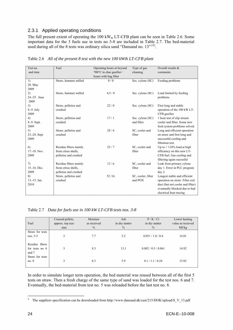
2.3.1 Applied operating conditions The full present extent of operating the 100 kWth LT-CFB plant can be seen in Table 2.6. Some important data for the 3 fuels use in tests no 3-8 are included in Table 2.7. The bed-material used during all of the 8 tests was ordinary silica sand “Dansand no. 13” [4].
Table 2.6 All of the present 8 test with the new 100 kWth LT-CFB plant Test no. and time
Fuel Operating hours at beyond 700°C in char gasifier / hours with bag filter
Type of gas cleaning
Overall results & comments
1) 28. May 2009
Straw, hammer milled 0 / 0 Sec. cylone (SC) Feeding problems
2) 24.-25. June 2009
Straw, hammer milled 4,5 / 0 Sec. cylone (SC) Load limited by feeding problems
3) 8.-9. July 2009
Straw, pelletise and crushed
22 / 0 Sec. cylone (SC) First long and stable operation of the 100 kW LT-CFB gasifier
4) 8.-9. Sept. 2009
Straw, pelletise and crushed
17 / 1 Sec. cylone (SC) and filter
1 hour test of slip stream cooler and filter. Some new feed system problems solved.
5) 23.-24. Sept 2009
Straw, pelletise and crushed
28 / 6 SC, cooler and filter
Long and efficient operation on straw and first long and successful cooling and filtration test.
6) 17.-18. Nov. 2009
Residue fibers mainly from citrus shells, pelletise and crushed
25 / 7 SC, cooler and filter
Up to > 110% load at high efficiency on this new LT-CFB fuel. Gas cooling and filtering again sucessful
7) 15.-16. Dec. 2009
Residue fibers mainly from citrus shells, pelletise and crushed
12 / 6 SC, cooler and filter
Leak from primary cylone day 1. Error in PLC program day 2.
8) 13.-15. Jan. 2010
Straw, pelletise and crushed
52 /16 SC, cooler, filter and POX
Longest stable and efficient operation on straw. Filter exit duct (but not cooler and filter) eventually blocked due to bad electrical heat tracing
Table 2.7 Data for fuels use in 100 kW LT-CFB tests nos. 3-8 Fuel
Crussed pellets, approx. top size
mm
Moisture as received
%
Ash in dry matter
%
P / K / Cl in dry matter
%
Lower heating value as recieved
MJ/kg Straw for tests nos. 3-5
3
7.7
5.2
0.051 / 1.0 / 0.4
16.01
Residue fibers for tests no 6 and 7
3
8.3
13.1
0.082 / 0.5 / 0.061
14.92
Straw for tests no. 8
3
8.3
5.9
0.1 / 1.1 / 0.24
15.82
In order to simulate longer term operation, the bed material was reused between all of the first 5 tests on straw. Then a fresh charge of the same type of sand was loaded for the test nos. 6 and 7. Eventually, the bed-material from test no. 5 was reloaded before the last test no. 8.
4 The suppliers specification can be downloaded from http://www.dansand.dk/cust/215/DOK/upload/S_V_13.pdf
24 ECN-E--10-008

As can be seen from Table 2.6, the very first two tests in May and June 2009 did not result in stable operation at full load. Besides dealing with various minor problems of practical nature (being usual for such a fully new test plant), the main problem was feeding loose hammer milled straw into the gasifier. Instead of wasting more time on attempting to avoid the blocking of the probably too narrow downwards connecting duct between the upper metering double screw and the lower faster rotating feeding screw, it was decided to instead feed the straw in the form of crushed pellets. This was done in all of the tests numbered 3 to 8. The new choice of fuel preparation led to the first operation at close to full load at July 8th and 9th 2009 and during the test no. 4 some further initial experiences with the new plant was gained, e.g. the functionality of the added gas cooling and cleaning system was initially tested. As planned within a “parallel” Danish PSO-2007 project, the 6th an 7th test were on a fuel prepared from residue fibres from the Danish company CP-Kelco, which produces pectin and caregenan based on respectively citrus shells. However, only the first of the two tests on these residue fibres (mainly from citrus shells) resulted in the intended many hours of operation. In the afterwards test no. 7 operation had to be terminated after some 12 hours due to a leak in the primary cyclone. During a restart the second day it was discovered that an error had been added to the PLC-programme which made further operation impossible. The last 100 kWth test no 8 was partly financed by a Danish PSO-2009 project led by DONG Energy, which is the reason why the fuel was now again straw and again it was in the form of crushed pellets. The aim was primarily to achieve many hours of stable and efficient operation at close to 100 % load and this way gain a better basis for evaluating the need for so called “bed particle management”, e.g. including the need for draining ash particles accumulated in the bed-material.
2.3.2 Experimental results A 1st important result to be mentioned is that during all of the 8 conducted 100 kWth tests, it was again possible to avoid ash melting problems. This was in spite of the mentioned choices of:
just using plain silica sand as the bed-material, not applying any other additives, the stated extensive re-use of bed-material.
In the late part of last test no 8 automatic temperature control on the char reaction chamber was successfully activated and a stepwise temperature increase was realised by increasing the temperature set point. The temperature increase to slightly above 760°C was also done in order to investigate if there was still a margin to the temperature that would result in de-fluidisation in the char reaction chamber and/or disturbed particle circulation. Fortunately, no problems appeared even though an afterward analysis of the bed material showed that potassium had accumulated to the level of 8.0%. This result, - showing the LT-CFB gasifiers capability of using even very difficult young agricultural fuels such as straw, - is consistant with the experiences gained with the two former 50 and 500 kW LT-CFB test plants. The mentioned 8 % potassium is however breaking an old “record” of 5.2% potassium in the bed material. The 100 kWth tests nos. 5, 6 and 8 is considered the most interesting in relation to the ERA-NET Bioenergy project activities concerning gas cooling and cleaning, i.e. further gas processing downstream the LT-CFB´s hot secondary cyclone. The full extent of operation during these 3 tests is illustrated by the 3 important process temperatures shown in Figure 2.15 to Figure 2.17.
ECN-E--10-008 25

Figure 2.15 Important process temperatures from 100 kWth LT-CFB test no. 5
Figure 2.16 Important process temperatures from 100 kWth LT-CFB test no. 6
Figure 2.17 Important process temperatures from 100 kWth LT-CFB test no. 8
26 ECN-E--10-008

The temperatures in Figure 2.15 to Figure 2.17 may not seam very stable, but this is mainly due to many short stops for refilling the fuel bin and the high compression of the time axis. The stability is better seen from Figure 2.18, showing the last approximately 6 hours of test no 8.
Figure 2.18 Important process temperatures from last 6 hours of 100 kWth LT-CFB test no. 8
The highest of the temperatures shown in all of the four figures above “KRT-2” is measured in the bubbling fluidized bed in the char reaction chamber. Here the temperature must be high enough to allow efficient char conversion without too much addition af steam/water, but preferably not so high that too much KCl evaporates and never so high that problematic ash melting takes place. The intermediate temperature “PKT-4” is measured in the pyrolysis chamber near the level of fuel feeding. Here the temperature must be high enough to achieve fast and efficient pyrolysis (leaving a small char residue) but not so high that PAH forms due to tar cracking. The last temperature, “SCT-ind” is measured between the two cyclones. Here it is important to keep the temperature down in order avoid that e.g. KCl escapes through the cyclones in gas phase. Some further results focussing on the 100 kWth LT-CFB gasifier, e.g. including performance data, will be presented in the report being prepared in the parallel PSO-2007 project.
ECN-E--10-008 27

28 ECN-E--10-008

3. Oil based gas washing (OLGA)
The oil based gas washing (OLGA) developed by ECN and Dahlman not only removes tars, but also dust as well as contaminants like thiophenes and dioxins from the product gas of a (biomass) gasifier [ 13 , 14 ]. At ECN, the OLGA technology is currently applied within the Substitute Natural Gas (SNG) production process based on indirect gasification. As OLGA removes tars, but not the valuable lighter hydrocarbons like methane, acetylene, and ethylene, it plays a crucial role in high-efficient SNG production processes. The OLGA in the past has been demonstrated successfully upstream Fischer-Tropsch (FT) diesel synthesis and in Combined Heat and Power (CHP) line ups as well though [13]. Although originally designed for tar removal downstream gasifiers operated at 800-900°C, the OLGA technology has been tested downstream gasifiers operated at lower temperatures as well, showing that OLGA is not limited to gasifiers operated at 800-900°C. As shown in Chapter 2, though, at lower temperatures, the tar composition shifts from large multiple ring tar components with high dew points to smaller single or double ring tar components with lower dew points. Furthermore, the tar composition will shift from rather stable non-polar components towards reactive polar components. As OLGA was originally designed to remove mainly non-polar tars, application of OLGA downstream gasifiers operated at lower temperatures will require some modifications. In this chapter, these modifications and the experimental results obtained with them are described in §3.2 and 3.3. It is also described how the OLGA can be integrated with the LT-CFB gasifier (§3.4). The chapter starts though with a short description of the OLGA (§3.1).
3.1 Description of OLGA The philosophy of OLGA is all about dew point control [15]. In Figure 3.1, the tar and water dew points are shown, together with the logical process steps. First, the product gas is cooled from the outlet temperature of the gasifier (typically 700–900°C) to the OLGA inlet temperature just above the tar dew point of the gas. Upstream OLGA, coarse solids are separated via cyclones. Fine solid aerosols are removed by OLGA. In OLGA, the tars are separated, first by condensation of heavy tars by cooling the gas from just above the tar dew point of the gas to just above the water dew point and secondly by absorption of light tars. The key philosophy in this is operating OLGA above the water dew point, while decreasing the tar dew point to a level under the lowest process temperature. As such, conventional water-based scrubbing technologies can be applied without mixing water and tars.
Figure 3.1 OLGA equipment selection based on dew points
ECN-E--10-008 29
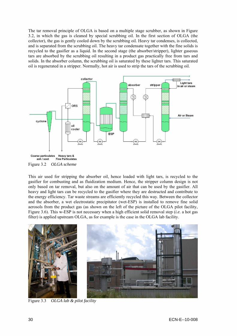
The tar removal principle of OLGA is based on a multiple stage scrubber, as shown in Figure 3.2, in which the gas is cleaned by special scrubbing oil. In the first section of OLGA (the collector), the gas is gently cooled down by the scrubbing oil. Heavy tar condenses, is collected, and is separated from the scrubbing oil. The heavy tar condensate together with the fine solids is recycled to the gasifier as a liquid. In the second stage (the absorber/stripper), lighter gaseous tars are absorbed by the scrubbing oil resulting in a product gas practically free from tars and solids. In the absorber column, the scrubbing oil is saturated by these lighter tars. This saturated oil is regenerated in a stripper. Normally, hot air is used to strip the tars of the scrubbing oil.
Figure 3.2 OLGA scheme
This air used for stripping the absorber oil, hence loaded with light tars, is recycled to the gasifier for combusting and as fluidization medium. Hence, the stripper column design is not only based on tar removal, but also on the amount of air that can be used by the gasifier. All heavy and light tars can be recycled to the gasifier where they are destructed and contribute to the energy efficiency. Tar waste streams are efficiently recycled this way. Between the collector and the absorber, a wet electrostatic precipitator (wet-ESP) is installed to remove fine solid aerosols from the product gas (as shown on the left of the picture of the OLGA pilot facility, Figure 3.6). This w-ESP is not necessary when a high efficient solid removal step (i.e. a hot gas filter) is applied upstream OLGA, as for example is the case in the OLGA lab facility.
Figure 3.3 OLGA lab & pilot facility
30 ECN-E--10-008

3.2 Required modifications for low-temperature gasification In order to take full advantage of low-temperature gasification, the OLGA must be modified to deal with different tars and higher concentrations than what OLGA originally has been designed for. The key issues refer to tar polymerisation, oil stability and viscosity, aerosol formation and capture, and overall performance of the tar removal technology. In the following paragraphs, the modifications required to (a) the cooling section, (b) the oil handling, and (c) the tar removal are discussed. The results of experiments performed after these modifications are described in §3.3.
3.2.1 The cooling section: the gas cooler and OLGA collector The cooling section of an integrated system of biomass gasification and OLGA tar removal consist out of two sections; the actual gas cooler downstream the biomass gasifier and the tar condensation step of OLGA, i.e. the collector. Although the outlet temperature of the gasifier is lower for low-temperature gasification and also the tar dew point is lower compared to “traditional” fluidized bed gasifiers operated at typically 850–950°C, the cooling section requires some specific attention. Although the dew point of the tars formed is lower, the amount of tars is significantly higher and in particular for an indirect gasifier like the MILENA. More importantly, the tars are much less stable; hence the risk of tar polymerization is significantly higher. As this polymerization is strongly depending on temperature and residence time, one should avoid condensation as far as possible and after condensation reduce the temperature as quickly as possible. On a pilot scale, this resulted in the reconstruction of the piping and cyclone upstream the OLGA, the actual gas inlet of the OLGA, and the (collector) oil cooling in OLGA (Figure 3.4).
(cyclone) (gas inlet) (oil cooler)
Figure 3.4 OLGA pilot scale modifications
During the testing of the pilot OLGA downstream the 500 kWth CFB gasifier BIVKIN in 2006 the operating temperatures of the cyclone and of the gas inlet were 400 and 350°C [16]. These temperatures however where only reached by the heating effect of the product gas. During start-up, temperatures where significantly lower, increasing the risk of initial fouling. Although not a serious problem in the duration tests of 2006, it was decided to change the setup in order to be able to operate the cyclone as well as the gas inlet of OLGA at temperatures of 450°C, well above the dew point of the product gas of the MILENA gasifier, hence avoiding any issues with tar condensation and possible polymerization in the piping upstream the OLGA. As a result of this increased temperature level of the gas entering the OLGA, the cooling duty of the collector column is increased (§3.3.3). In order to cope with this increased cooling duty, the capacity of the collector oil cooling has to be increased. Additional cooling capacity is therefore installed within the collector oil loop, using the already existing connections of the superfluous oil filters within this collector oil loop of the pilot OLGA. The oil filters became superfluous due to the application of the oil recovery system (§3.2.2).
ECN-E--10-008 31

3.2.2 The oil handling: the oil recovery system (ORS) The oil recovery system (ORS) is designed in order to separate dust as well as the heavy fraction of the tars from the collector oil loop, while maintaining the light fraction of the tars within this loop. As such, it is capable of (a) removing the surplus of tars collected from the product gas, (b) removing any dust slipped through the cyclones and/or HGF upstream OLGA, and (c) controlling the viscosity of the oil in the collector loop. The ORS allows operation on collector oil with a constant viscosity, without the need for supply of fresh collector oil. Furthermore, as the ESP is integrated into the collector oil loop, it enables complete dust removal from the collector oil, hence the product gas. The principle of the ORS is based on partial evaporation of the collector oil (Figure 3.5). The vaporous lighter fraction is send to the gas inlet of OLGA by a sweeping gas and hence kept within the OLGA collector loop. The heavy fraction, including fine solids, is pumped out of the ORS as a liquid stream suitable as e.g. feedstock for the gasifier. The pumping of this liquid stream also sets demands to the viscosity of this stream; hence the ORS ultimately controls both the viscosity of the collector oil and of the surplus of tars extracted from the OLGA.
Figure 3.5 ORS scheme
(lab) (pilot)
Figure 3.6 ORS lab & pilot facility
32 ECN-E--10-008
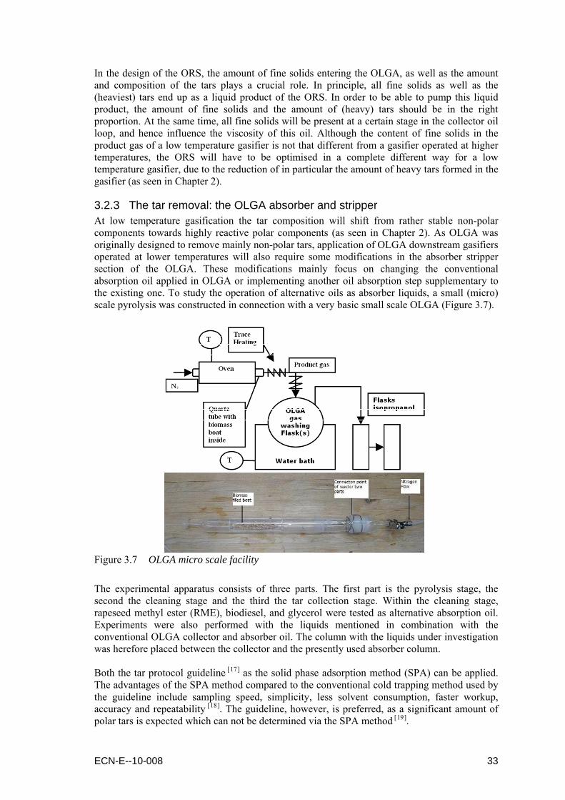
In the design of the ORS, the amount of fine solids entering the OLGA, as well as the amount and composition of the tars plays a crucial role. In principle, all fine solids as well as the (heaviest) tars end up as a liquid product of the ORS. In order to be able to pump this liquid product, the amount of fine solids and the amount of (heavy) tars should be in the right proportion. At the same time, all fine solids will be present at a certain stage in the collector oil loop, and hence influence the viscosity of this oil. Although the content of fine solids in the product gas of a low temperature gasifier is not that different from a gasifier operated at higher temperatures, the ORS will have to be optimised in a complete different way for a low temperature gasifier, due to the reduction of in particular the amount of heavy tars formed in the gasifier (as seen in Chapter 2).
3.2.3 The tar removal: the OLGA absorber and stripper At low temperature gasification the tar composition will shift from rather stable non-polar components towards highly reactive polar components (as seen in Chapter 2). As OLGA was originally designed to remove mainly non-polar tars, application of OLGA downstream gasifiers operated at lower temperatures will also require some modifications in the absorber stripper section of the OLGA. These modifications mainly focus on changing the conventional absorption oil applied in OLGA or implementing another oil absorption step supplementary to the existing one. To study the operation of alternative oils as absorber liquids, a small (micro) scale pyrolysis was constructed in connection with a very basic small scale OLGA (Figure 3.7).
Figure 3.7 OLGA micro scale facility
The experimental apparatus consists of three parts. The first part is the pyrolysis stage, the second the cleaning stage and the third the tar collection stage. Within the cleaning stage, rapeseed methyl ester (RME), biodiesel, and glycerol were tested as alternative absorption oil. Experiments were also performed with the liquids mentioned in combination with the conventional OLGA collector and absorber oil. The column with the liquids under investigation was herefore placed between the collector and the presently used absorber column. Both the tar protocol guideline [17] as the solid phase adsorption method (SPA) can be applied. The advantages of the SPA method compared to the conventional cold trapping method used by the guideline include sampling speed, simplicity, less solvent consumption, faster workup, accuracy and repeatability [18]. The guideline, however, is preferred, as a significant amount of polar tars is expected which can not be determined via the SPA method [19].
ECN-E--10-008 33

3.3 Experimental results
3.3.1 OLGA micro scale The micro scale OLGA was mainly used to determine the possibility to use OLGA downstream gasification at very low temperature (e.g. pyrolysis) or gasification at varying temperatures (e.g. updraft gasification). The fuel used in the micro scale gasifier (Figure 3.7) to produce the product gas is beech wood and the temperature was set at 400°C. Close to this point mostly carbonyls, alcohols and ethers, in general more polar compounds, are produced [20,21]. During three tests, RME, biodiesel and glycerol are applied in order to remove these components from the product gas. In Figure 3.8 to Figure 3.10, the removal efficiency is presented, also showing that some components are already removed by the oils conventionally applied in the OLGA collector and absorber.
Figure 3.8 OLGA micro scale with RME scrubber
Figure 3.9 OLGA micro scale with biodiesel scrubber
Figure 3.10 OLGA micro scale with glycerol scrubber
34 ECN-E--10-008

When only one column containing the alternative scrubbing liquid RME, biodiesel or glycerol is used, the cleaning efficiency η (representing the amount of tars absorbed-collected in the liquid(s) over the total amount of tars produced, including those which were condensed and did not pass through the cleaning stage) was found to be 33% for the RME and 73% for the glycerol. This is an implication that both liquids may improve the efficiency towards removal of “polar” tar compounds, although glycerol seems to be much more efficient than RME. Biodiesel was only studied in combination with a conventionally operated collector and absorber. The new column with the biodiesel was placed between the collector and the presently used absorber column. The results showed that the efficiency (η) under these conditions was 58% for OLGA in combination with a biodiesel scrubber. For RME under similar setup, this was 44%. Again glycerol showed to be more efficient, with an overall efficiency of OLGA and the glycerol scrubber of 94%.
3.3.2 OLGA lab scale Tests with the OLGA on lab scale were performed downstream the WOB gasifier operated at lower temperatures (§2.2) without modifying the OLGA, hence applying the conventionally used oils. Due to the initial problems with chlorine in the product gas5, only the collector of OLGA was applied downstream the RDF gasification tests. During the gasification of beech wood and PE, the complete OLGA was applied. In Figure 3.11 the tar composition of the product gas of RDF gasification at 750 as well as 850ºC is presented, both downstream the WOB gasifier and downstream the OLGA collector. As the collector is designed in order to cool the gas to a temperature just above the water dewpoint, the collector mainly removes the heavier tar components. The lighter tar components are only removed fractionally in the collector and should normally be removed in the absorption step of OLGA. Besides the issues with the chlorine based thermoplast formation, no issues with OLGA downstream the RDF gasifier were observed. The efficiency of the absorber was not tested though during the RDF gasification.
Figure 3.11 OLGA performance downstream RDF gasification at 750 & 850°C
5 During the RDF gasification tests, condensation was encountered of an unusual thermoplast in the temperature
area of 150 to 200ºC. Although the thermoplast softens and melts on heating similar to tars, its liquid viscosity is that high compared with “conventional” tars that it plugged the collector column of the OLGA [13]. It is thought that the reaction towards the thermoplast can be attributed to the combined presence of (i) the polystyrene in the RDF fuel, (ii) the also highly present chlorine as a catalyst for the polymerization reactions, and (iii) at least one other tar component, likely released from another component present in the RDF fuel [8]. Although the thermoplast can be removed from the oil via the ORS (§3.3.4), chlorine removal upstream OLGA is preferred. By removing chlorine upstream the OLGA, formation of the thermoplast could successfully be avoided and tar removal with OLGA operated as expected and without any further problems [13].
ECN-E--10-008 35
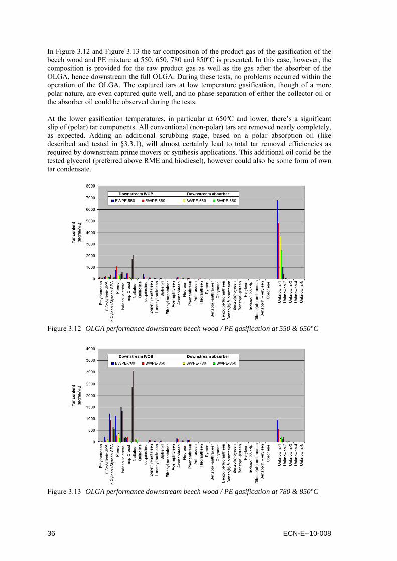
In Figure 3.12 and Figure 3.13 the tar composition of the product gas of the gasification of the beech wood and PE mixture at 550, 650, 780 and 850ºC is presented. In this case, however, the composition is provided for the raw product gas as well as the gas after the absorber of the OLGA, hence downstream the full OLGA. During these tests, no problems occurred within the operation of the OLGA. The captured tars at low temperature gasification, though of a more polar nature, are even captured quite well, and no phase separation of either the collector oil or the absorber oil could be observed during the tests. At the lower gasification temperatures, in particular at 650ºC and lower, there’s a significant slip of (polar) tar components. All conventional (non-polar) tars are removed nearly completely, as expected. Adding an additional scrubbing stage, based on a polar absorption oil (like described and tested in §3.3.1), will almost certainly lead to total tar removal efficiencies as required by downstream prime movers or synthesis applications. This additional oil could be the tested glycerol (preferred above RME and biodiesel), however could also be some form of own tar condensate.
Figure 3.12 OLGA performance downstream beech wood / PE gasification at 550 & 650°C
Figure 3.13 OLGA performance downstream beech wood / PE gasification at 780 & 850°C
36 ECN-E--10-008
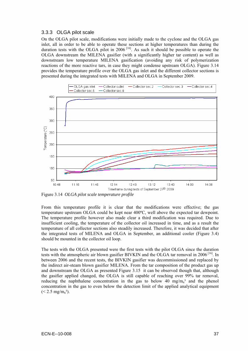
3.3.3 OLGA pilot scale On the OLGA pilot scale, modifications were initially made to the cyclone and the OLGA gas inlet, all in order to be able to operate these sections at higher temperatures than during the duration tests with the OLGA pilot in 2006 [16]. As such it should be possible to operate the OLGA downstream the MILENA gasifier (with a significantly higher tar content) as well as downstream low temperature MILENA gasification (avoiding any risk of polymerization reactions of the more reactive tars, in case they might condense upstream OLGA). Figure 3.14 provides the temperature profile over the OLGA gas inlet and the different collector sections is presented during the integrated tests with MILENA and OLGA in September 2009.
Figure 3.14 OLGA pilot scale temperature profile
From this temperature profile it is clear that the modifications were effective; the gas temperature upstream OLGA could be kept near 400ºC, well above the expected tar dewpoint. The temperature profile however also made clear a third modification was required. Due to insufficient cooling, the temperature of the collector oil increased in time, and as a result the temperature of all collector sections also steadily increased. Therefore, it was decided that after the integrated tests of MILENA and OLGA in September, an additional cooler (Figure 3.4) should be mounted in the collector oil loop. The tests with the OLGA presented were the first tests with the pilot OLGA since the duration tests with the atmospheric air blown gasifier BIVKIN and the OLGA tar removal in 2006 [16]. In between 2006 and the recent tests, the BIVKIN gasifier was decommissioned and replaced by the indirect air-steam blown gasifier MILENA. From the tar composition of the product gas up and downstream the OLGA as presented Figure 3.15 it can be observed though that, although the gasifier applied changed, the OLGA is still capable of reaching over 99% tar removal, reducing the naphthalene concentration in the gas to below 40 mg/mn³ and the phenol concentration in the gas to even below the detection limit of the applied analytical equipment (< 2.5 mg/mn³).
ECN-E--10-008 37

Figure 3.15 OLGA pilot scale performance downstream the MILENA gasifier
3.3.4 ORS lab scale The ORS was first tested on a lab scale, and although positioned in a lam flow cabinet (Figure 3.6), this facility has a capacity already more than sufficient for the lab scale OLGA. The goal of this ORS facility was to demonstrate the technical feasibility of the patented ORS [22], hence separating the collector oil into a light (gaseous) fraction and a (heavy) fraction. For the tests with the ORS, the collector oil from the OLGA pilot scale duration tests [16] was initially applied, though after succesfull testing with this oil (Figure 3.16), also more complicated oils were used, i.e. the oil from the lab scale OLGA after the tests downstream RDF gasification as well as pilot scale duration tests mixed with substantial levels of (fine) dust.
Figure 3.16 ORS lab scale products Figure 3.17 ORS lab scale separation of
thermoplast from collector oil
The tests with the “contaminated” lab scale OLGA collector oil showed that when cooling the vaporous fraction obtained from the ORS, initially the thermoplast would condense, and only in a later stage of cooling the actually to be recovered components. The viscosity of the thermoplast was still high enough in order not to plug the cooler (Figure 3.17), and hence could be separated from the gaseous fraction that ultimately should be returned to the OLGA collector. Although a promising way to separate the thermoplast “contamination” from the collector oil, research in this field was not continued as avoiding thermoplast formation (by removing chlorine upstream OLGA) should be the preferred alternative (see footnote 5).
38 ECN-E--10-008

The test with the lab scale ORS facility showed that in order to obtain an acceptable recovery rate, the application of a sweep gas would be required, even at temperature levels within the ORS of 280ºC or higher. It also revealed that in order to provide sufficient gas-liquid contact time, it would be possible to apply the same materials used in the columns of the OLGA. It will be necessary though to apply more than the one section applied on the lab scale ORS.
3.3.5 ORS pilot scale Based on the experiments with the lab scale ORS therefore a larger ORS facility was constructed, capable of handling the amount of collector oil that has to be treated on the pilot scale OLGA. This pilot scale ORS (Figure 3.6) was commissioned within half a year and used to determine the most critical parameters of the ORS, i.e. (i) the acceptable ratios between dust and oil including (heavy) tars, and (ii) the achievable recovery yield. 3.3.5.1 The dust/oil ratio Within the OLGA, the viscosity of oil and tars plays a crucial role. This relates to both the oil circulating within the collector loop of the OLGA as well as the (heavy) tar separated from the ORS. The viscosity of the oil is determined on the one hand by the tars present in the oil and on the other hand by the dust still present in the raw gas after the cyclone upstream OLGA. Too much dust (or too few tars) will result in an unacceptable increase of the viscosity. In order to determine what dust-to-oil ratios are acceptable, therefore, long time tests with the viscometer installed in the ORS were performed. At the beginning of each test, the dust-to-oil ratio was adjusted, before the dust/oil mixture was pumped around at different temperature levels. The measured viscosity levels during these tests are presented in Figure 3.18, for oil based on 100% pilot duration test oil to oils with increasing amounts of fine dust.
0
50
100
150
200
250
300
350
400
40 45 50 55 60 65 70 75 80 85 90 95 100 105 110Temperature
(°C)
Vis
cosi
ty(c
P)
Pilot oil with 0.0% additional dustPilot oil with 12.7% additional dustPilot oil with 22.5% additional dustPilot oil with 30.0% additional dust
Figure 3.18 ORS pilot scale effect of dust/tar ratio on oil viscosity
Based on the experiences with the OLGA facilities at ECN and in Moissannes, France, an acceptable viscosity of the oil in the collector loop is 100 cP or lower. The lowest temperature level of this oil in the collector loop is approximately 70 to 80ºC, i.e. just above the water dewpoint of the gas. This means that the maximum acceptable dust concentration in the collector loop is somewhere between 5 and 10%. For the (heavy) tar fraction obtained from the ORS the temperature level will be somewhere between 200 and 300ºC. As such, for this dust/tar fraction, a much higher dust content is acceptable.
ECN-E--10-008 39

As such, the critical design parameter of the ORS is the amount of light fraction, separated from the collector oil and send back to the OLGA collector. The more light fraction is separated, the lower the dust/tar ratio becomes, as basically the raw product gas is provided with more condensable tars. The design of the ORS, of course, is strongly depending on the efficiency of the cyclones applied, and the initial tar composition of the gas, i.e. the operating conditions of the gasifier. 3.3.5.2 The recovery yield During the tests with the lab scale ORS it was revealed that (with one column section) it would be necessary to operate at a temperature level of over 280C and with an amount of sweep gas in ln/min almost equal to the amount of oil to be treated in kg/hr. First tests with the pilot scale ORS (with four active sections) showed that even higher temperatures should be preferred in order to achieve a significant recovery yield. As research on the ORS is still in the early stages, and exact recovery yields desired are not yet known, as these not only depend on the gasifier, but also on the tar composition (hence gasifier operating conditions), a operating line was determined for the ORS. This operating line, representing the recovery yield of light fraction as a function of the amount of sweep gas applied, is presented in Figure 3.19. In the graph, the recovery yield is determined for both fresh collector oil (as would be used during start-up of an OLGA) as for the pilot duration test oil (already containing relatively more heavy tars).
0
10
20
30
40
50
60
70
80
0.0 0.3 0.6 0.9 1.2 1.5 1.8
Sweep gas(ln/min gas per kg/hr oil)
Yie
ld(w
t.%lig
ht fr
actio
n)
Collector oil from pilot duration testCollector oil as used during start-up
Figure 3.19 ORS pilot scale recovery yield of the light fraction at 320ºC
With expected recovery yields needed of about 40-60% for a MILENA gasifier, the higher values valid for gasification at lower temperatures, it can be concluded that over 0.4 ln/min sweep gas per kg/hr oil might be needed. Although this amount will not significantly influence the composition and the calorific value of the final product (not even when using nitrogen), the consumption might be considered as that significant that (cleaned) product gas should be applied as sweep gas instead of a gas delivered by a third party. Again, though, this will strongly depend on the gasification plant, size and infrastructures present. For the MILENA gasification process, the exact conditions for the ORS to be operated on are not yet determined completely. Like for other OLGA designs, the still ongoing research on the ORS will provide significant amount of information on how to optimise the design as well as the operation of the total OLGA system.
40 ECN-E--10-008

3.4 Integration of OLGA and LT-CFB In this paragraph the integration of the OLGA system and the LT-CFB gasifier is described. The theoretical process design of the OLGA system is based on data provided by DFBT and Risø DTU on the 100 kWth LT-CFB gasifier. As some specific data has not become available in time for the design, Dahlman has based the design also on a number of assumptions. As such, a number of reservations and recommendations to this design have to be reported (§3.4.3).
3.4.1 Available process input data The following data are provided by Mr. Stoholm from DFBT and Mr. Ahrenfeldt from Risø DTU
Table 3.1 LT-CFB 100 kWth feedstock data
Parameter Value Unit Remarks Feedstock type Danish straw Feedstock mass flow 19 kg/hrdry Feedstock moisture content 10 wt.% Maximal feedstock moisture content 20 wt.% Limited by expectable feeding problems
Table 3.2 LT-CFB 100 kWth fuel composition
Component Valuedry Valuewet Unit Remark Heating value 18.5 17.5 MJ/kg HHV basis H2O (water/moisture) 10 wt.% C (carbon) wt.% H2 (hydrogen) wt.% N2 (nitrogen) wt.% O2 (oxygen) wt.% Ash 5 wt.% Estimate S (sulfur) wt.% Cl (chloride) wt.% Sum wt.%
Table 3.3 LT-CFB 100 kWth raw product gas composition (outlet gasifier)
Component Valuedry Valuewet Unit CO2 14.5 vol.% H2O 6 0.0 18.4 vol.% N2 59.0 vol.% CO 16.3 vol.% H2 3.5 vol.% O2 0.0 0.0 vol.% CH4 4.3 vol.% C2Hy 1.4 vol.% C3Hy … C5Hy 0.3 vol.% C6Hy 0.0 vol.% Total gas 7 99.3 vol.%
Table 3.4 LT-CFB 100 kWth stripper / gasifier air or steam
Parameter Value Unit Remark Type Air [-] Air mass flow 22 kg/hr Temperature of 20 °C and Pressure of 0.25 bar(g) Steam mass flow - kg/hr Preferred temperature at gasifier inlet Not specified °C Preferred pressure at gasifier inlet Not specified bara
6 DTU and DFBT provided a figure of 0.15 kg H2O/kgdry gas , which is, based on the assumed density of the gas of
approximately 1.2 kg/mn³, calculated to be a water content of 18.4 vol.%. 7 Raw product gas composition does not include data on argon concentration.
ECN-E--10-008 41

Table 3.5 LT-CFB 100 kWth product gas at inlet OLGA
Parameter Value Unit Remark Gas mass flow 43 kg/hr At approx 90 % load Gas mass flow (minimal) 30 kg/hr –30 % (Approx. 60% of 100%) Gas mass flow (maximal) 52 kg/hr +20 % (Approx. 110% of 100%) Normal gas flow - mn³/hr (mn³/hr at 0°C and 1 bara) assume e.g. 1,2 kg/mn³ Normal gas flow (minimal) - mn³/hr Normal gas flow (maximal) - mn³/hr Actual gas flow - ma³/hr 650 degrees Celsius provided by Mr. Peder Stoholm Actual gas flow (minimal) - ma³/hr Actual gas flow (maximal) - ma³/hr Density (normal) Product Gas 1,2 kg/mn³ Assumption Density (actual) Product Gas - kg/ma³ Gas temperature outlet gasifier 650 °C Gas inlet temperature OLGA Not specified °C Water dew point operating 61.5 °C Calculated, based on water content of 18.4 vol% Maximal design water dew point Not specified °C Operating pressure inlet OLGA 1 bara Energy content product gas 0,093 MJ MJ/s assumed! HHV product gas 7,3 MJ/mn³ Assumed density: 1.2 kg/mn³ LHV product gas 8,7 MJ/mn³
Table 3.6 LT-CFB 100 kWth solid particles at inlet OLGA
Parameter Value Unit Remark Total dust load inlet OLGA operating 0.045 kg/hr Total dust concentration inlet OLGA operating 1257 mg/mn³dry
Assumed 80% retention in bed and 80% in settling chamber +25%
Maximal dust concentration inlet OLGA maximal 1000-2000 mg/mn³dry Specified by Dahlman
Table 3.7 LT-CFB 100 kWth tar data (simplified) at inlet OLGA
Parameter Value Unit Remark Tar dew point 190 °C Result from 500 kW test on biogas residue Total tar mass flow Not specified kg/hr Tar concentration 4800 mg/mn³dry Based on LT-CFB #3 Phenol concentration 910 mg/mn³dry Based on LT-CFB #3 Phenol concentration 769 mg/mn³dry Calculated, based on LT-CFB #3 and 18.4 vol% H2O Naphthalene concentration 33 mg/mn³dry Based on LT-CFB #3 Naphthalene concentration 28 mg/mn³dry Calculated, based on LT-CFB #3 and 18.4 vol% H2O Sum PAH 125 mg/mn³dry Based on LT-CFB #3
Table 3.8 LT-CFB 100 kWth tar data (composition) at inlet OLGA
Sample Unit LT-CFB #1 LT-CFB #2 LT-CFB #3 Tar gravimetric (80°C 16h) g/mn³ 38.2 24.2 4.8 Total volatile tar (GCMS) g/mn³ 33.3 21.9 4.1 Phenol g/mn³ 1.9 0.72 0.31 Total volatile phenol (GCMS) g/mn³ 6.0 2.95 0.91 Naphthalene mg/mn³ 232 108 33 Methyl-naphthalene mg/mn³ 334 135 72 Acenaphthene mg/mn³ 12 5.1 2.5 Acenaphthylene mg/mn³ 32 9.6 7.6 Fluorine mg/mn³ 30 9.6 4.1 Phenanthrene mg/mn³ 30 15.4 5.3 Anthracene mg/mn³ <0.5 <0.5 <0.5 Fluoranthene mg/mn³ 0.9 2.6 0.2 Pyrene mg/mn³ 6.0 6.7 1.1 Sum PAH mg/mn³ 676 294 125
Table 3.9 LT-CFB 100 kWth inorganic impurities data at inlet OLGA
Parameter Value Unit Remark NH3 concentration after gasifier Not specified mg/mn³dry H2S concentration after gasifier Not specified mg/mn³dry HCL concentration after gasifier Not specified mg/mn³dry Other impurities Not specified mg/mn³dry
For a detailed OLGA design, types and concentrations should be specified
42 ECN-E--10-008
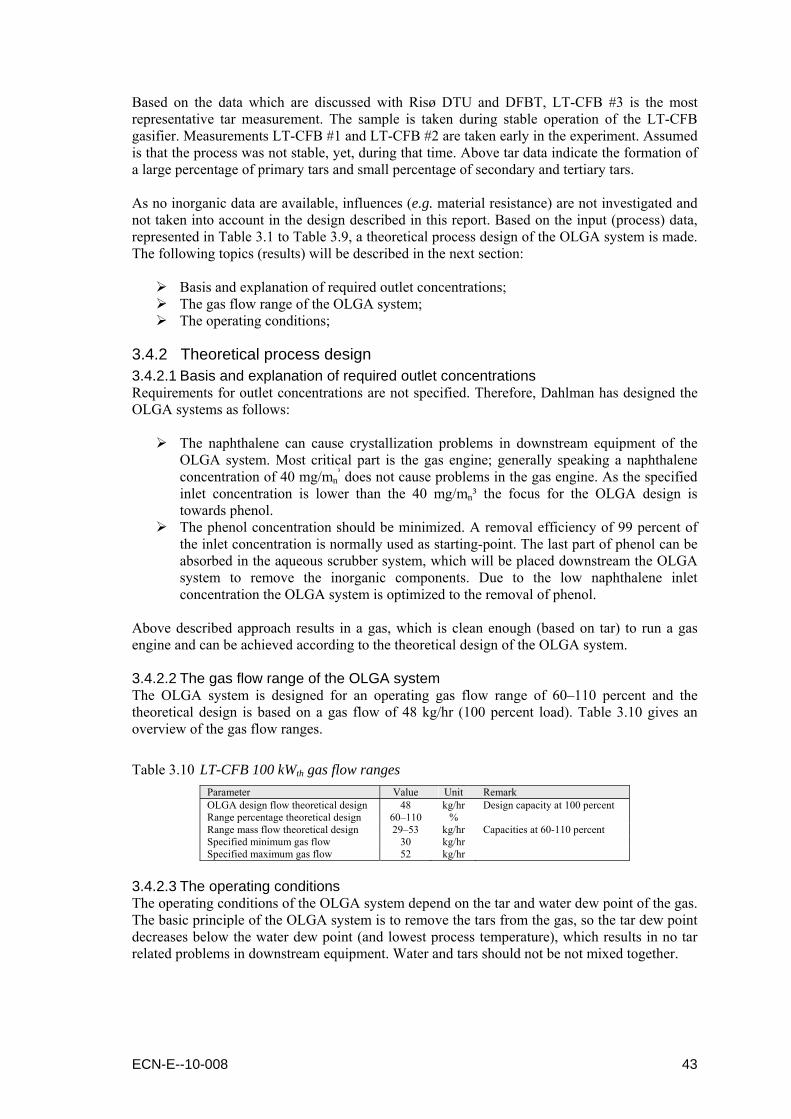
Based on the data which are discussed with Risø DTU and DFBT, LT-CFB #3 is the most representative tar measurement. The sample is taken during stable operation of the LT-CFB gasifier. Measurements LT-CFB #1 and LT-CFB #2 are taken early in the experiment. Assumed is that the process was not stable, yet, during that time. Above tar data indicate the formation of a large percentage of primary tars and small percentage of secondary and tertiary tars. As no inorganic data are available, influences (e.g. material resistance) are not investigated and not taken into account in the design described in this report. Based on the input (process) data, represented in Table 3.1 to Table 3.9, a theoretical process design of the OLGA system is made. The following topics (results) will be described in the next section:
Basis and explanation of required outlet concentrations; The gas flow range of the OLGA system; The operating conditions;
3.4.2 Theoretical process design 3.4.2.1 Basis and explanation of required outlet concentrations Requirements for outlet concentrations are not specified. Therefore, Dahlman has designed the OLGA systems as follows:
The naphthalene can cause crystallization problems in downstream equipment of the OLGA system. Most critical part is the gas engine; generally speaking a naphthalene concentration of 40 mg/mn
³ does not cause problems in the gas engine. As the specified inlet concentration is lower than the 40 mg/mn³ the focus for the OLGA design is towards phenol.
The phenol concentration should be minimized. A removal efficiency of 99 percent of the inlet concentration is normally used as starting-point. The last part of phenol can be absorbed in the aqueous scrubber system, which will be placed downstream the OLGA system to remove the inorganic components. Due to the low naphthalene inlet concentration the OLGA system is optimized to the removal of phenol.
Above described approach results in a gas, which is clean enough (based on tar) to run a gas engine and can be achieved according to the theoretical design of the OLGA system. 3.4.2.2 The gas flow range of the OLGA system The OLGA system is designed for an operating gas flow range of 60–110 percent and the theoretical design is based on a gas flow of 48 kg/hr (100 percent load). Table 3.10 gives an overview of the gas flow ranges.
Table 3.10 LT-CFB 100 kWth gas flow ranges
Parameter Value Unit Remark OLGA design flow theoretical design 48 kg/hr Design capacity at 100 percent Range percentage theoretical design 60–110 % Range mass flow theoretical design 29–53 kg/hr Capacities at 60-110 percent Specified minimum gas flow 30 kg/hr Specified maximum gas flow 52 kg/hr
3.4.2.3 The operating conditions The operating conditions of the OLGA system depend on the tar and water dew point of the gas. The basic principle of the OLGA system is to remove the tars from the gas, so the tar dew point decreases below the water dew point (and lowest process temperature), which results in no tar related problems in downstream equipment. Water and tars should not be not mixed together.
ECN-E--10-008 43

Figure 3.20 LT-CFB 100 kWth basic OLGA working principle
Product gas: Temperature Based on, the process input data as described in §3.4.1, and especially Table 3.7 and Table 3.8, an estimate for the tar dew point is made to 300–350 degrees Celsius. This estimate is higher than the tar dew point reported for the LT-CFB in Chapter 4 (200–250°C), as well as the tar dew point specified by DFBT and Risø DTU for the OLGA design when operated on biogas residues (190°C, Table 3.7) mainly on three reasons:
The specified tar dew point is based on another biomass feedstock; The complete tar analysis is not available, yet; Unknowns cannot be specified and influence to tar dew point cannot be indicated.
The 300–350 degrees Celsius result in an OLGA gas inlet temperature of 400 degrees Celsius. Based on the specified gas composition and estimated water content of 18.4 vol.%, gas pressure and gas temperature as described in §3.4.1, the water dew point of the gas is determined (Table 3.11). The maximum water dew point cannot be calculated due to a lack of information. Based on the operating case and a safe margin, the theoretical design is made. If more information comes available the water dew point and operating temperature should be evaluated.
Table 3.11 LT-CFB 100 kWth water dew point gas
H2O [vol.%] Water dewpoint [@ 1100 mbar(a)] Unit Operating case 18.4 61.5 °C Maximum case TBD TBD °C
Product gas: Pressure For safety reasons the electrostatic precipitator (ESP) should work on a positive pressure, minimal 5 mbar(g). Based on the air inlet pressure of 1250 mbar(a), an inlet pressure of the OLGA system of approximately 1100 mbar(a) is assumed, which will result in a positive pressure in the ESP. Air: pressure and temperature The specified air pressure of 1250 mbar(a) is evaluated in the theoretical process design and based on the current available data, the stripper column can work at this “elevated” pressure. The temperature of the air should be increased from 20 degrees Celsius to 180 degrees Celsius. The second oil loop works as a classical absorber / stripper system. To strip the tars from the oil towards the air, the temperature should be elevated.
44 ECN-E--10-008

In the collector column the gas temperature is decreased to a value which is safely above the water dew point. Heavy tars (secondary / tertiary) will condense in the oil. Dust and possible formed aerosols will be removed in the ESP. In the second loop a classical absorber / stripper system light tars are removed. Phenol and naphthalene are the key components used for the theoretical process design and will be removed as explained at the beginning of this paragraph.
3.4.3 Remarks on the design Based on the (limited) available process data a theoretical process design is made for the OLGA system. The theoretical process design shows that the tars, and especially naphthalene and phenol (key components for design) can be removed to low enough levels that a gas engine should run (based on tars). However, due to the low gasification temperature some reservations and recommendations should be made, namely;
Complete tar, primary, secondary and tertiary components and C3+, analysis should be executed. Results should be evaluated;
Influences of formation of more primary (polar) tar components should be investigated in detail. The removal of primary (polar) tar components in comparison to secondary and tertiary tars is less efficient (they pass through the collector column). Other types of oil for the first oil loop or an additional column with a third oil can possibly be investigated (§3.2.3);
For good operation of collector column the ratio of dust and heavy tars is important. Based on the available tar and dust data, mixture is not optimal; an increase of the viscosity of the oil is expected. Dust and complete tar data should be investigated in detail.
ECN-E--10-008 45

46 ECN-E--10-008

4. Filtration and partial oxidation
4.1 Purpose and Background
4.1.1 Bag House Filtration The purpose of this study is to prove that it is possible to filter the gas from a LT-CFB gasifier in a commercially available bag house filter at temperatures around 300°C. The traditional way to clean the gas from the LT-CFB gasifier includes only cyclones. This approach leaves a considerable amount of particles in the gas, and thereby limits the potential usage. If the last particles were removed the gas could be used for multiple additional purposes, e.g. in gas boilers, and other equipment that does not tolerate particles. Previous studies have shown that the tar dew point of gas from the LT-CFB gasifier is somewhere between 200 and 250°C. As it is possible to purchase affordable and commercially available bag house filters that functions in temperatures as high as 370°C [ 23 ], it seemed reasonable to conduct the filter experiments with gas temperatures above the tar dew point. At these temperatures clogging of the bag house filters by liquid tars is avoided.
4.1.2 Partial Oxidation The producer gas leaving a biomass gasifier normally contains more or less tar depending on the design of the gasifier and the type of biomass used as fuel. The partial oxidation of the gas results in a significantly reduction of the tar. Primary and secondary tars are oxidized or converted to tertiary tars during this partial oxidation [24]. The partial oxidation of the pyrolysis gas can be recognized as one of the main reasons for the almost “tar-free” producer gas from a staged gasifier [24,25]. Other investigations concerning partial oxidation of pyrolysis gas are reported in the literature. Brandt and Henriksen [26] investigated partial oxidation of pyrolysis gas produced by straw with focus on the total amount of tar, while Ledesma et al. [ 27 ] investigated partial oxidation of pyrolysis gas produced by bituminous coal with focus on the formation and fate of polycyclic aromatic hydrocarbons (PAH). In the following sections selected results of these two investigations will briefly be mentioned. 4.1.2.1 Partial oxidation of pyrolysis gas from straw Brandt and Henriksen [26] investigated partial oxidation of pyrolysis gas produced by straw with focus on the total amount of tar. The pyrolysis gas was generated by slow pyrolysis of straw at 600°C with a solid residence time of 23 minutes in the pyrolysis unit. The partial oxidation was carried out at two different temperatures namely at 800 and 900°C. The residence time in the partial oxidation reactor was approximately 2 seconds. In Figure 4.1 results from these partial oxidation experiments are shown. The figure shows the amount of tar collected in the condenser and in the aerosol filter as a function of the excess air ratio at two different oxidation temperatures.
ECN-E--10-008 47

Figure 4.1 Results from partial oxidation experiments At an excess air ratio (related to the combustion of the volatile pyrolysis products) of 0.3 a considerable reduction of tar can be seen. The minimum tar content measured was 0.5 gram per kg dry straw at 900°C with an excess air ratio of about 0.5. This corresponds to a tar reduction of 98% compared to no addition of air at the same temperature [26]. In addition it can be seen that the amount of tar at excess air ratios higher than 0.3 are not changing significantly with respect to temperature. The composition of the tar was not investigated [26]. Concerning the gas species after the partial oxidation the investigations also showed that the volume of H2 and CO given relative to the fuel input were approx. constant with respect to the excess air ratio while the volume of CH4 was reduced at higher λ [26]. 4.1.2.2 Partial oxidation of pyrolysis gas from bituminous coal Ledesma et al. [27] investigated partial oxidation of pyrolysis gas produced by bituminous coal with focus on the formation and fate of polycyclic aromatic hydrocarbons (PAH). These experiments were carried out in a two-stage quartz reactor. In the first stage volatiles that predominantly consisted of primary tar from coal pyrolysis were generated in a fluidized-bed at 600°C with a heating rate in the order of 104 K/s. In the second stage the volatiles (primary tar) were reacted under either pyrolytic or oxidizing conditions in a tubular-flow reactor at 1000°C. The residence time in the tubular-flow reactor was approximately 1 second. In Figure 4.2 selected results from the experiments are shown. The mass yields shown are based on the mass of primary tar entering the tubular-flow reactor.
Figure 4.2 Yields of naphthalene, phenanthrene and anthracene (left) as well as pyrene,
benzanthracene and chrysene (right) as function of the excess air ratio
48 ECN-E--10-008
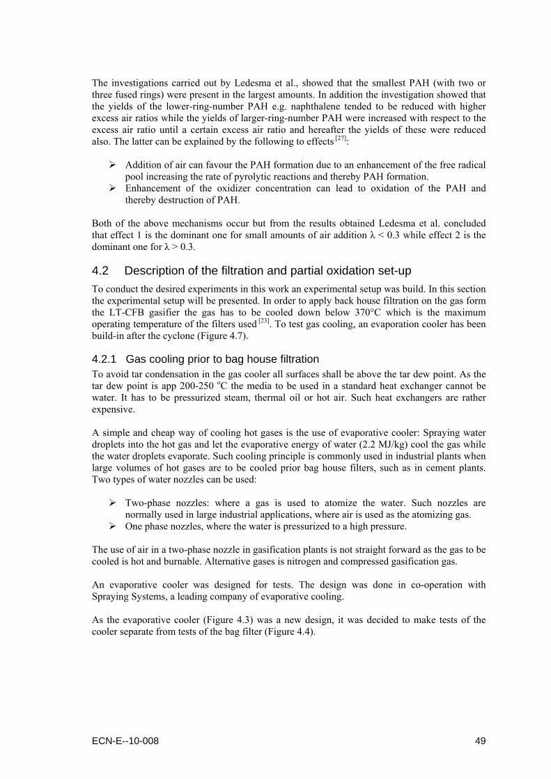
The investigations carried out by Ledesma et al., showed that the smallest PAH (with two or three fused rings) were present in the largest amounts. In addition the investigation showed that the yields of the lower-ring-number PAH e.g. naphthalene tended to be reduced with higher excess air ratios while the yields of larger-ring-number PAH were increased with respect to the excess air ratio until a certain excess air ratio and hereafter the yields of these were reduced also. The latter can be explained by the following to effects [27]:
Addition of air can favour the PAH formation due to an enhancement of the free radical pool increasing the rate of pyrolytic reactions and thereby PAH formation.
Enhancement of the oxidizer concentration can lead to oxidation of the PAH and thereby destruction of PAH.
Both of the above mechanisms occur but from the results obtained Ledesma et al. concluded that effect 1 is the dominant one for small amounts of air addition λ < 0.3 while effect 2 is the dominant one for λ > 0.3.
4.2 Description of the filtration and partial oxidation set-up To conduct the desired experiments in this work an experimental setup was build. In this section the experimental setup will be presented. In order to apply back house filtration on the gas form the LT-CFB gasifier the gas has to be cooled down below 370°C which is the maximum operating temperature of the filters used [23]. To test gas cooling, an evaporation cooler has been build-in after the cyclone (Figure 4.7).
4.2.1 Gas cooling prior to bag house filtration To avoid tar condensation in the gas cooler all surfaces shall be above the tar dew point. As the tar dew point is app 200-250 oC the media to be used in a standard heat exchanger cannot be water. It has to be pressurized steam, thermal oil or hot air. Such heat exchangers are rather expensive. A simple and cheap way of cooling hot gases is the use of evaporative cooler: Spraying water droplets into the hot gas and let the evaporative energy of water (2.2 MJ/kg) cool the gas while the water droplets evaporate. Such cooling principle is commonly used in industrial plants when large volumes of hot gases are to be cooled prior bag house filters, such as in cement plants. Two types of water nozzles can be used:
Two-phase nozzles: where a gas is used to atomize the water. Such nozzles are normally used in large industrial applications, where air is used as the atomizing gas.
One phase nozzles, where the water is pressurized to a high pressure. The use of air in a two-phase nozzle in gasification plants is not straight forward as the gas to be cooled is hot and burnable. Alternative gases is nitrogen and compressed gasification gas. An evaporative cooler was designed for tests. The design was done in co-operation with Spraying Systems, a leading company of evaporative cooling. As the evaporative cooler (Figure 4.3) was a new design, it was decided to make tests of the cooler separate from tests of the bag filter (Figure 4.4).
ECN-E--10-008 49

Figure 4.3 CFD simulation of evaporative cooler for the 100 kWth LT CFB gasifier
Figure 4.4 Test of nozzle (left), evaporative cooler without insulation (centre) and evaporative
cooler with insulation (right)
50 ECN-E--10-008
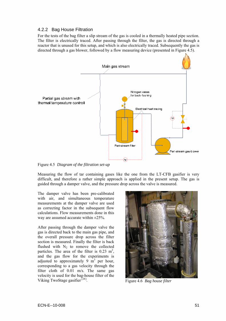
4.2.2 Bag House Filtration For the tests of the bag filter a slip stream of the gas is cooled in a thermally heated pipe section. The filter is electrically traced. After passing through the filter, the gas is directed through a reactor that is unused for this setup, and which is also electrically traced. Subsequently the gas is directed through a gas blower, followed by a flow measuring device (presented in Figure 4.5).
Figure 4.5 Diagram of the filtration set-up Measuring the flow of tar containing gases like the one from the LT-CFB gasifier is very difficult, and therefore a rather simple approach is applied in the present setup. The gas is guided through a damper valve, and the pressure drop across the valve is measured. The damper valve has been pre-calibrated with air, and simultaneous temperature measurements at the damper valve are used as correcting factor in the subsequent flow calculations. Flow measurements done in this way are assumed accurate within ±25%. After passing through the damper valve the gas is directed back to the main gas pipe, and the overall pressure drop across the filter section is measured. Finally the filter is back flushed with N2 to remove the collected particles. The area of the filter is 0.23 m2, and the gas flow for the experiments is adjusted to approximately 9 m3 per hour, corresponding to a gas velocity through the filter cloth of 0.01 m/s. The same gas velocity is used for the bag-house filter of the Viking TwoStage gasifier [28].
Figure 4.6 Bag house filter
ECN-E--10-008 51

4.2.3 Partial Oxidation During the partial oxidation (POX) experiments (diagram of the setup is presented in Figure 4.7) a small flow of producer gas is mixed with air and nitrogen, just before entering the partial oxidation reactor. The partial oxidation reactor is surrounded by an oven that is electrically heated to the desired temperature. The heating of the oven is done in two zones to accomplish a better temperature control of the partial oxidation reactor.
Figure 4.7 Diagram of the gas cleaning set-up Preheated air and nitrogen are mixed with the producer gas just before entering the partial oxidation reactor (Figure 4.8). Mass flow controllers are used to control the flow of nitrogen and air and after these the mixed nitrogen and air is preheated typically to a temperature of 600°C. For sampling of the tars after the POX reactor a Petersen Column [29] was used, as presented in Figure 4.9. The solvent used was isopropanol.
Gas from the pyrolysis unit
Steam
Air/nitrogen
460 mm
T7 T8 T9 T10 T11 T12 T13 T14
Figure 4.8 Schematic drawing of the partial oxidation reactor
52 ECN-E--10-008

Figure 4.9 The Petersen Column setup
POX Reactor
Petersen Column
Figure 4.10 Partial oxidation (POX) and tar sampling setup
ECN-E--10-008 53
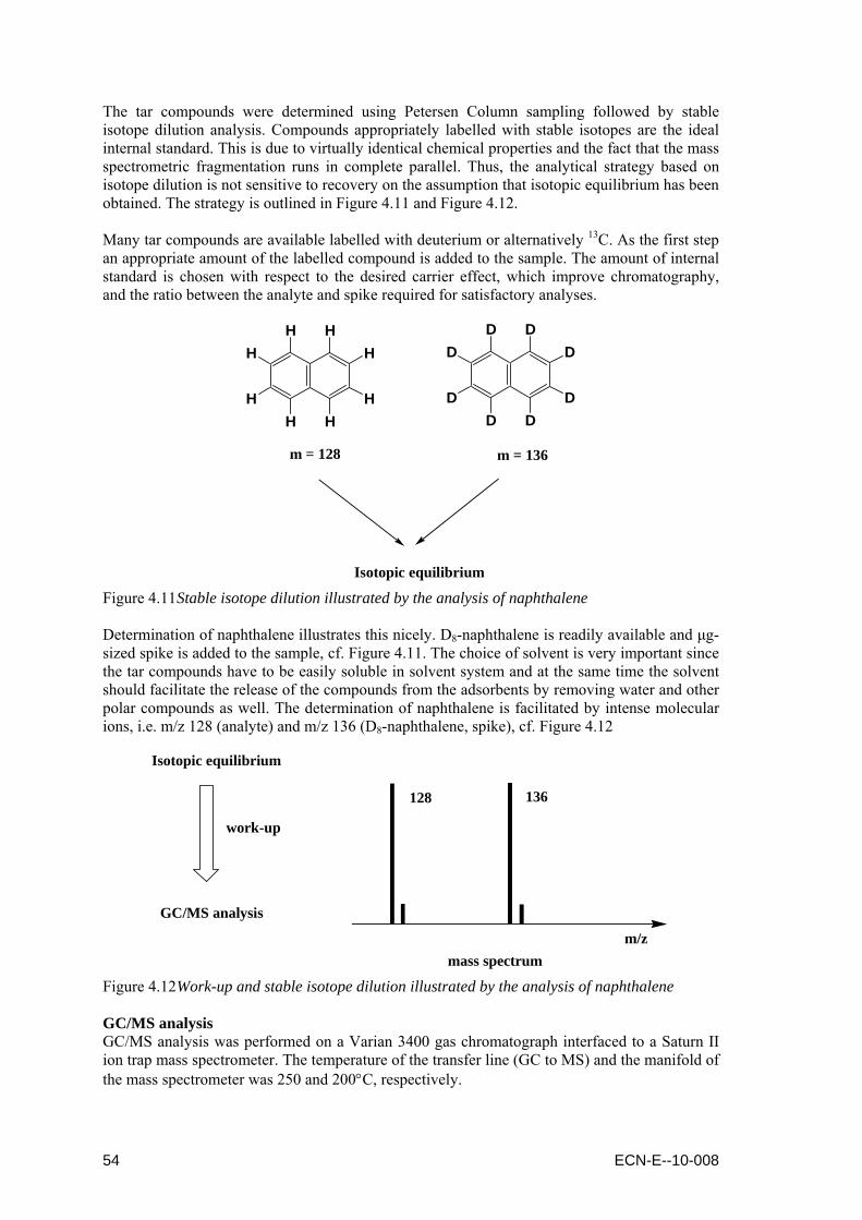
The tar compounds were determined using Petersen Column sampling followed by stable isotope dilution analysis. Compounds appropriately labelled with stable isotopes are the ideal internal standard. This is due to virtually identical chemical properties and the fact that the mass spectrometric fragmentation runs in complete parallel. Thus, the analytical strategy based on isotope dilution is not sensitive to recovery on the assumption that isotopic equilibrium has been obtained. The strategy is outlined in Figure 4.11 and Figure 4.12. Many tar compounds are available labelled with deuterium or alternatively 13C. As the first step an appropriate amount of the labelled compound is added to the sample. The amount of internal standard is chosen with respect to the desired carrier effect, which improve chromatography, and the ratio between the analyte and spike required for satisfactory analyses.
m = 128 m = 136
Isotopic equilibrium
H HH
HHH
H
HD D
D
DDD
D
D
Figure 4.11 Stable isotope dilution illustrated by the analysis of naphthalene Determination of naphthalene illustrates this nicely. D8-naphthalene is readily available and μg-sized spike is added to the sample, cf. Figure 4.11. The choice of solvent is very important since the tar compounds have to be easily soluble in solvent system and at the same time the solvent should facilitate the release of the compounds from the adsorbents by removing water and other polar compounds as well. The determination of naphthalene is facilitated by intense molecular ions, i.e. m/z 128 (analyte) and m/z 136 (D8-naphthalene, spike), cf. Figure 4.12
Isotopic equilibrium
GC/MS analysis
work-up
mass spectrumm/z
128 136
Figure 4.12 Work-up and stable isotope dilution illustrated by the analysis of naphthalene GC/MS analysis GC/MS analysis was performed on a Varian 3400 gas chromatograph interfaced to a Saturn II ion trap mass spectrometer. The temperature of the transfer line (GC to MS) and the manifold of the mass spectrometer was 250 and 200°C, respectively.
54 ECN-E--10-008

ECN-E--10-008 55
The tar compounds was separated using a 0.32 mm x 25m WCOT fused silica column coated with CP-SIL 8CB at a thickness of 0.25 μm. 1μL samples were introduced in split mode (approximately 1:50) at a temperature of 250°C. Separation of a wide range of compounds was achieved using a temperature program from 50 to 270°C.
4.3 Experimental results
4.3.1 Gas Cooling The gas cooler has been tested during gasifier operation on two different fuels, once for operation on straw and once for operation on pectin residues. During both tests the full gas stream was cooled down. Figure 4.13 shows an example of the temperature distribution in the cooler as well as the inlet and outlet temperatures. It can be seen that cooling is achieved as desired and that the temperatures can be controlled. The duration of the cooling tests was limited due to the risk of tar condensation further downstream of the cooler. A part of the downstream piping and the gas burner is placed outside of gasifier-building and thus cold weather enhanced this risk.
19:30 20:00 20:30 21:00 21:30 22:00 22:30 23:00 23:30 0:00250
300
350
400
450
500
17
GCT 1GCT 2GCT 3GCT 5GCT 6GCT 7
19:30 20:00 20:30 21:00 21:30 22:00 22:30 23:00 23:30 0:00Time [hr:min]
200
300
400
500
600
Gas
Coo
ler T
emp e
ratu
res
[deg
. C]
17
GCT INGCT OUT
Figure 4.13 Gas cooler temperatures from tests during gasifier operation on pectin residues When inspected after the tests the cooler showed no sign of tar condensation, only a fine layer of dust was seen on cooler walls (Figure 4.14). From the bottom of the cooler some ash and sand particles could be collected but also here no signs of tar condensation were seen (Figure 4.15).
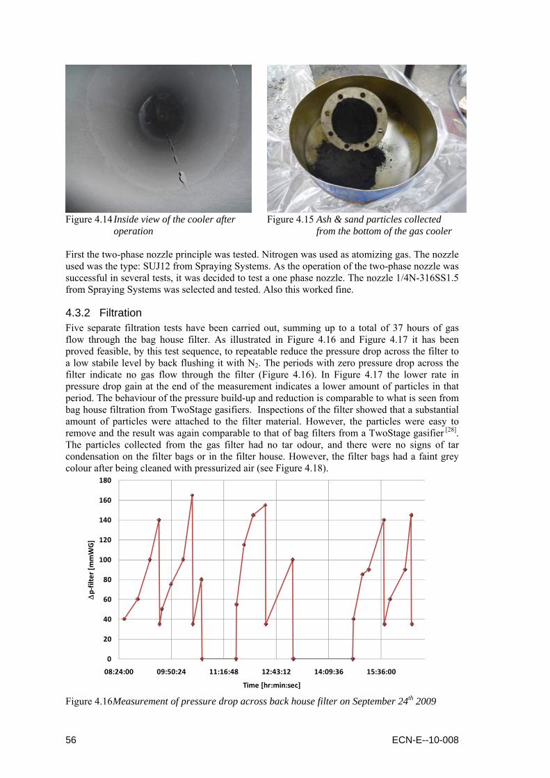
Figure 4.14 Inside view of the cooler after
operation
Figure 4.15 Ash & sand particles collected
from the bottom of the gas cooler First the two-phase nozzle principle was tested. Nitrogen was used as atomizing gas. The nozzle used was the type: SUJ12 from Spraying Systems. As the operation of the two-phase nozzle was successful in several tests, it was decided to test a one phase nozzle. The nozzle 1/4N-316SS1.5 from Spraying Systems was selected and tested. Also this worked fine.
4.3.2 Filtration Five separate filtration tests have been carried out, summing up to a total of 37 hours of gas flow through the bag house filter. As illustrated in Figure 4.16 and Figure 4.17 it has been proved feasible, by this test sequence, to repeatable reduce the pressure drop across the filter to a low stabile level by back flushing it with N2. The periods with zero pressure drop across the filter indicate no gas flow through the filter (Figure 4.16). In Figure 4.17 the lower rate in pressure drop gain at the end of the measurement indicates a lower amount of particles in that period. The behaviour of the pressure build-up and reduction is comparable to what is seen from bag house filtration from TwoStage gasifiers. Inspections of the filter showed that a substantial amount of particles were attached to the filter material. However, the particles were easy to remove and the result was again comparable to that of bag filters from a TwoStage gasifier [28]. The particles collected from the gas filter had no tar odour, and there were no signs of tar condensation on the filter bags or in the filter house. However, the filter bags had a faint grey colour after being cleaned with pressurized air (see Figure 4.18).
0
20
40
60
80
100
120
140
160
180
08:24:00 09:50:24 11:16:48 12:43:12 14:09:36 15:36:00
Δp‐filter [mmWG]
Time [hr:min:sec]
Figure 4.16 Measurement of pressure drop across back house filter on September 24th 2009
56 ECN-E--10-008
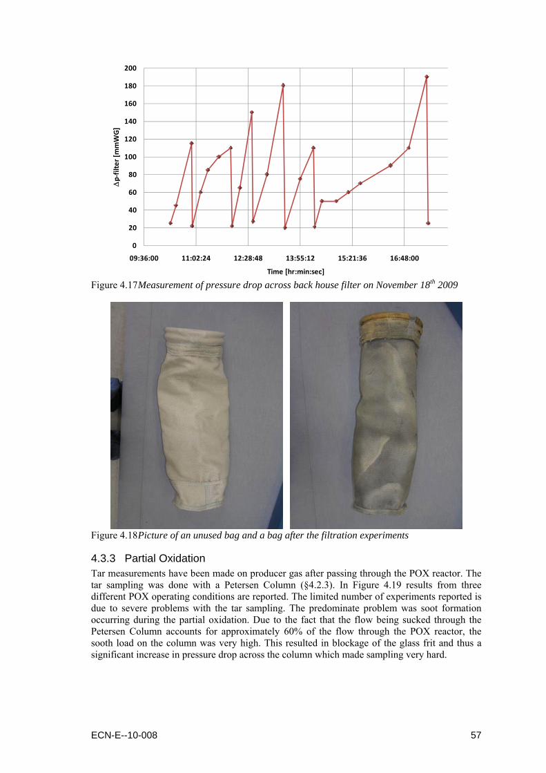
0
20
40
60
80
100
120
140
160
180
200
09:36:00 11:02:24 12:28:48 13:55:12 15:21:36 16:48:00
Δp‐filter [mmWG]
Time [hr:min:sec] Figure 4.17 Measurement of pressure drop across back house filter on November 18th 2009
Figure 4.18 Picture of an unused bag and a bag after the filtration experiments
4.3.3 Partial Oxidation Tar measurements have been made on producer gas after passing through the POX reactor. The tar sampling was done with a Petersen Column (§4.2.3). In Figure 4.19 results from three different POX operating conditions are reported. The limited number of experiments reported is due to severe problems with the tar sampling. The predominate problem was soot formation occurring during the partial oxidation. Due to the fact that the flow being sucked through the Petersen Column accounts for approximately 60% of the flow through the POX reactor, the sooth load on the column was very high. This resulted in blockage of the glass frit and thus a significant increase in pressure drop across the column which made sampling very hard.
ECN-E--10-008 57
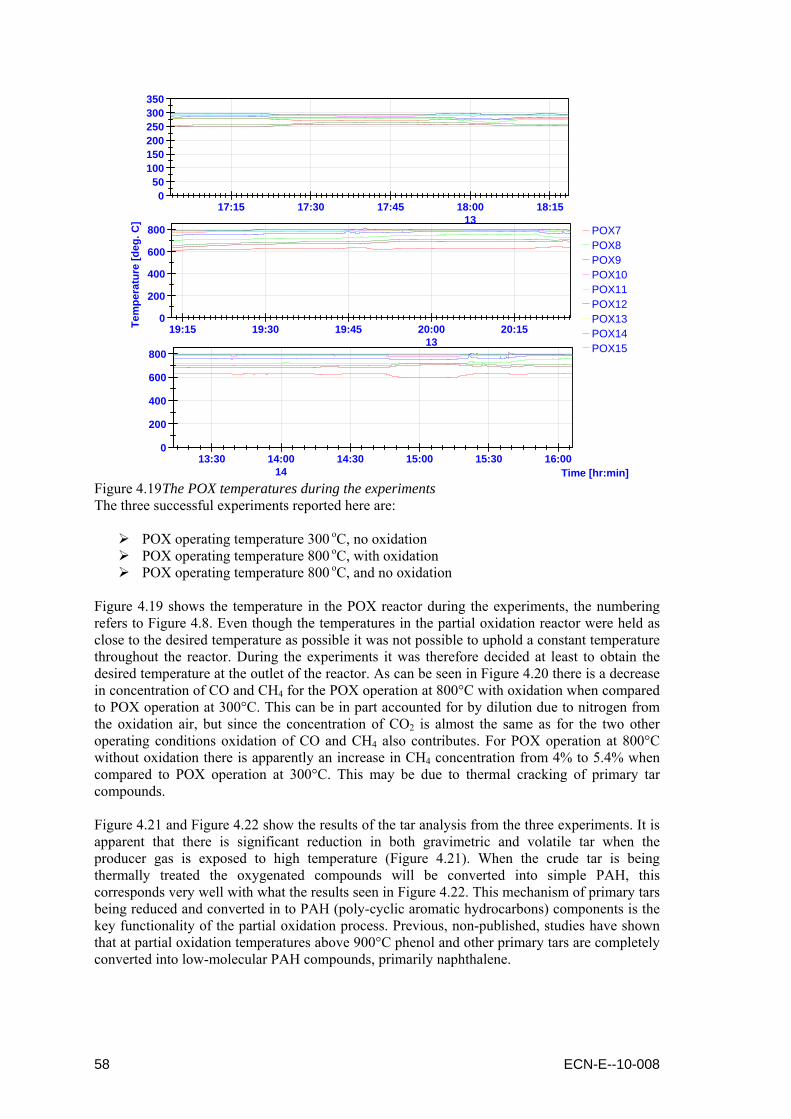
19:15 19:30 19:45 20:00 20:150
200
400
600
800
Tem
pera
t ure
[deg
. C]
13
17:15 17:30 17:45 18:00 18:150
50100150200250300350
13POX7POX8POX9POX10POX11POX12POX13POX14POX15
13:30 14:00 14:30 15:00 15:30 16:00Time [hr:min]
0
200
400
600
800
14 Figure 4.19 The POX temperatures during the experiments The three successful experiments reported here are:
POX operating temperature 300 oC, no oxidation POX operating temperature 800 oC, with oxidation POX operating temperature 800 oC, and no oxidation
Figure 4.19 shows the temperature in the POX reactor during the experiments, the numbering refers to Figure 4.8. Even though the temperatures in the partial oxidation reactor were held as close to the desired temperature as possible it was not possible to uphold a constant temperature throughout the reactor. During the experiments it was therefore decided at least to obtain the desired temperature at the outlet of the reactor. As can be seen in Figure 4.20 there is a decrease in concentration of CO and CH4 for the POX operation at 800°C with oxidation when compared to POX operation at 300°C. This can be in part accounted for by dilution due to nitrogen from the oxidation air, but since the concentration of CO2 is almost the same as for the two other operating conditions oxidation of CO and CH4 also contributes. For POX operation at 800°C without oxidation there is apparently an increase in CH4 concentration from 4% to 5.4% when compared to POX operation at 300°C. This may be due to thermal cracking of primary tar compounds. Figure 4.21 and Figure 4.22 show the results of the tar analysis from the three experiments. It is apparent that there is significant reduction in both gravimetric and volatile tar when the producer gas is exposed to high temperature (Figure 4.21). When the crude tar is being thermally treated the oxygenated compounds will be converted into simple PAH, this corresponds very well with what the results seen in Figure 4.22. This mechanism of primary tars being reduced and converted in to PAH (poly-cyclic aromatic hydrocarbons) components is the key functionality of the partial oxidation process. Previous, non-published, studies have shown that at partial oxidation temperatures above 900°C phenol and other primary tars are completely converted into low-molecular PAH compounds, primarily naphthalene.
58 ECN-E--10-008
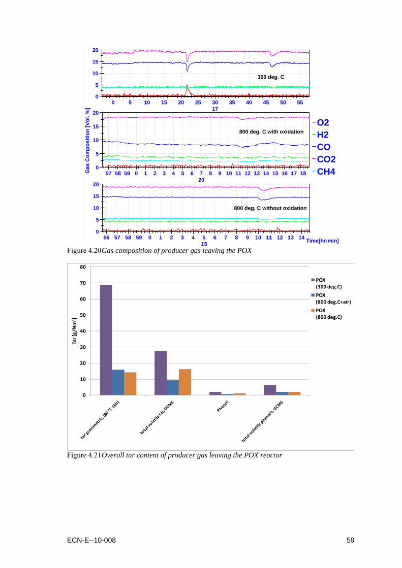
0 5 10 15 20 25 30 35 40 45 50 550
5
10
15
20
17
O2H2COCO2CH457 58 59 0 1 2 3 4 5 6 7 8 9 10 11 12 13 14 15 16 17 18
0
5
10
15
20
Gas
Com
posi
tion
[Vol
. %]
20
56 57 58 59 0 1 2 3 4 5 6 7 8 9 10 11 12 13 14 Time[hr:min]0
5
10
15
20
15
800 deg. C without oxidation
300 deg. C
800 deg. C with oxidation
Figure 4.20 Gas composition of producer gas leaving the POX
0
10
20
30
40
50
60
70
80
Tar [g/Nm
3 ]
POX (300 deg.C)
POX (800 deg.C+air)
POX (800 deg.C)
Figure 4.21 Overall tar content of producer gas leaving the POX reactor
ECN-E--10-008 59
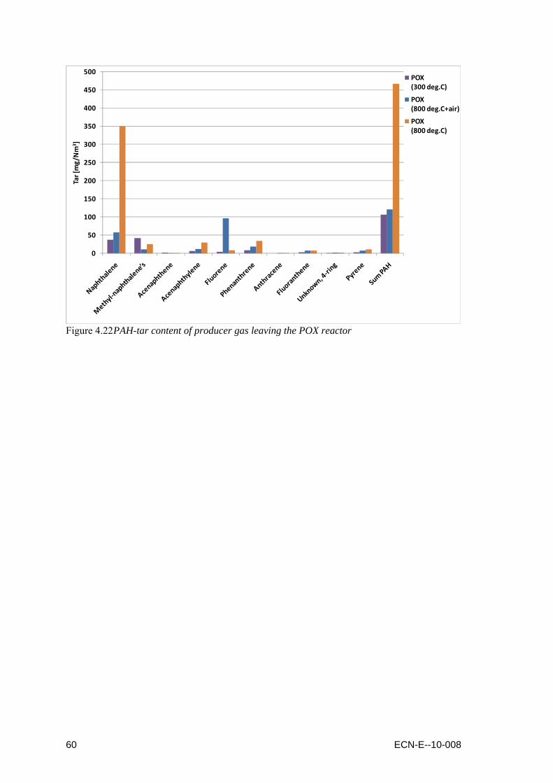
0
50
100
150
200
250
300
350
400
450
500Tar [mg/Nm
3 ]POX (300 deg.C)
POX (800 deg.C+air)
POX (800 deg.C)
Figure 4.22 PAH-tar content of producer gas leaving the POX reactor
60 ECN-E--10-008
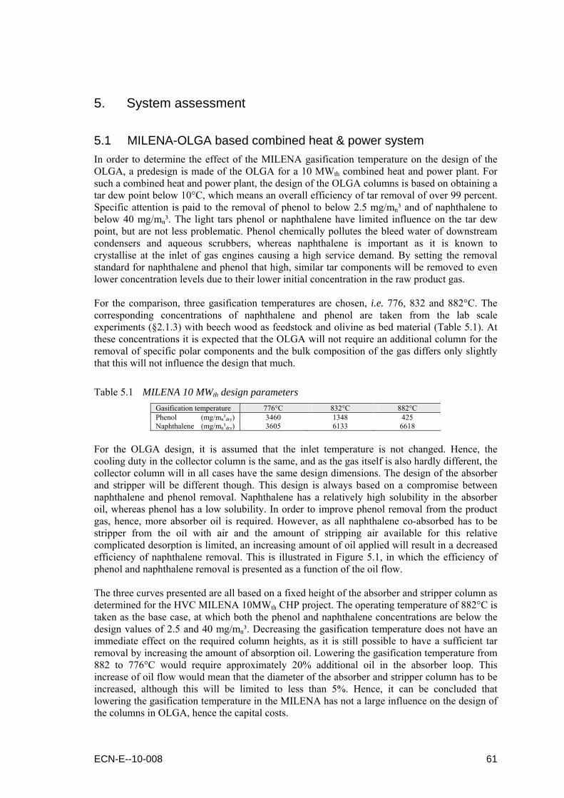
5. System assessment
5.1 MILENA-OLGA based combined heat & power system In order to determine the effect of the MILENA gasification temperature on the design of the OLGA, a predesign is made of the OLGA for a 10 MWth combined heat and power plant. For such a combined heat and power plant, the design of the OLGA columns is based on obtaining a tar dew point below 10°C, which means an overall efficiency of tar removal of over 99 percent. Specific attention is paid to the removal of phenol to below 2.5 mg/mn³ and of naphthalene to below 40 mg/mn³. The light tars phenol or naphthalene have limited influence on the tar dew point, but are not less problematic. Phenol chemically pollutes the bleed water of downstream condensers and aqueous scrubbers, whereas naphthalene is important as it is known to crystallise at the inlet of gas engines causing a high service demand. By setting the removal standard for naphthalene and phenol that high, similar tar components will be removed to even lower concentration levels due to their lower initial concentration in the raw product gas. For the comparison, three gasification temperatures are chosen, i.e. 776, 832 and 882°C. The corresponding concentrations of naphthalene and phenol are taken from the lab scale experiments (§2.1.3) with beech wood as feedstock and olivine as bed material (Table 5.1). At these concentrations it is expected that the OLGA will not require an additional column for the removal of specific polar components and the bulk composition of the gas differs only slightly that this will not influence the design that much.
Table 5.1 MILENA 10 MWth design parameters
Gasification temperature 776°C 832°C 882°C Phenol (mg/mn³dry) 3460 1348 425 Naphthalene (mg/mn³dry) 3605 6133 6618
For the OLGA design, it is assumed that the inlet temperature is not changed. Hence, the cooling duty in the collector column is the same, and as the gas itself is also hardly different, the collector column will in all cases have the same design dimensions. The design of the absorber and stripper will be different though. This design is always based on a compromise between naphthalene and phenol removal. Naphthalene has a relatively high solubility in the absorber oil, whereas phenol has a low solubility. In order to improve phenol removal from the product gas, hence, more absorber oil is required. However, as all naphthalene co-absorbed has to be stripper from the oil with air and the amount of stripping air available for this relative complicated desorption is limited, an increasing amount of oil applied will result in a decreased efficiency of naphthalene removal. This is illustrated in Figure 5.1, in which the efficiency of phenol and naphthalene removal is presented as a function of the oil flow. The three curves presented are all based on a fixed height of the absorber and stripper column as determined for the HVC MILENA 10MWth CHP project. The operating temperature of 882°C is taken as the base case, at which both the phenol and naphthalene concentrations are below the design values of 2.5 and 40 mg/mn³. Decreasing the gasification temperature does not have an immediate effect on the required column heights, as it is still possible to have a sufficient tar removal by increasing the amount of absorption oil. Lowering the gasification temperature from 882 to 776°C would require approximately 20% additional oil in the absorber loop. This increase of oil flow would mean that the diameter of the absorber and stripper column has to be increased, although this will be limited to less than 5%. Hence, it can be concluded that lowering the gasification temperature in the MILENA has not a large influence on the design of the columns in OLGA, hence the capital costs.
ECN-E--10-008 61
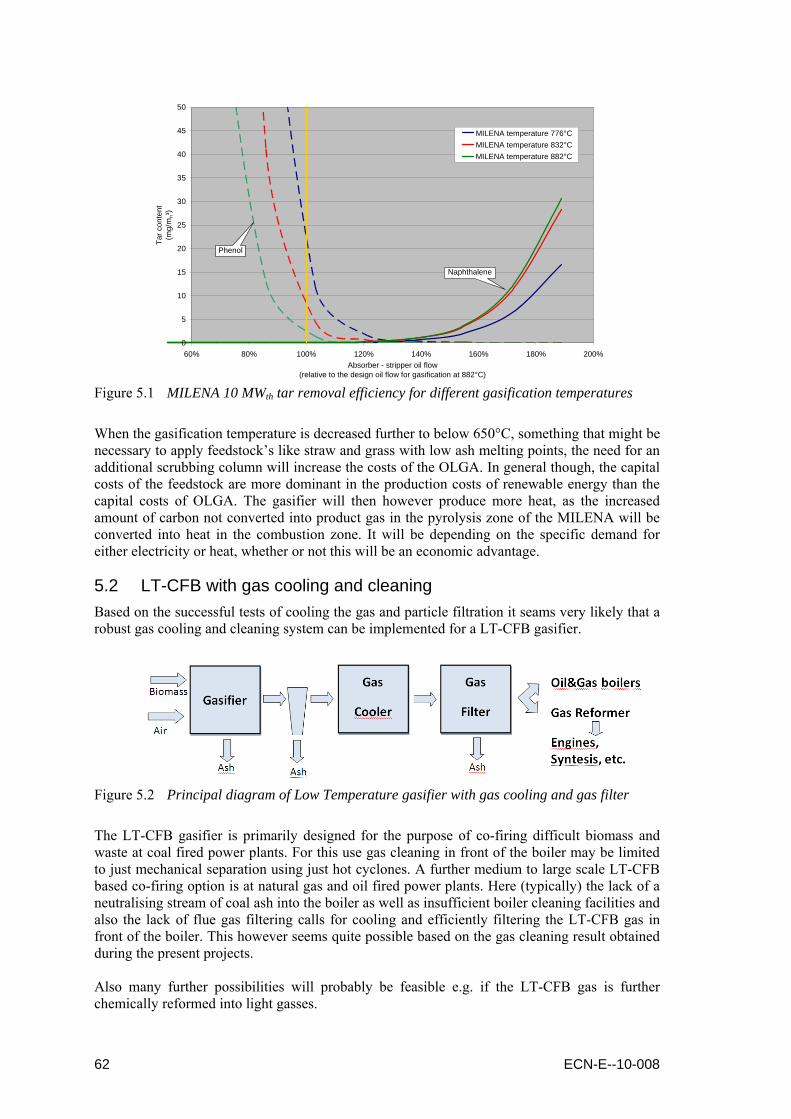
0
5
10
15
20
25
30
35
40
45
50
60% 80% 100% 120% 140% 160% 180% 200%Absorber - stripper oil flow
(relative to the design oil flow for gasification at 882°C)
Tar c
onte
nt(m
g/m
n³)
MILENA temperature 776°CMILENA temperature 832°CMILENA temperature 882°C
Phenol
Naphthalene
Figure 5.1 MILENA 10 MWth tar removal efficiency for different gasification temperatures
When the gasification temperature is decreased further to below 650°C, something that might be necessary to apply feedstock’s like straw and grass with low ash melting points, the need for an additional scrubbing column will increase the costs of the OLGA. In general though, the capital costs of the feedstock are more dominant in the production costs of renewable energy than the capital costs of OLGA. The gasifier will then however produce more heat, as the increased amount of carbon not converted into product gas in the pyrolysis zone of the MILENA will be converted into heat in the combustion zone. It will be depending on the specific demand for either electricity or heat, whether or not this will be an economic advantage.
5.2 LT-CFB with gas cooling and cleaning Based on the successful tests of cooling the gas and particle filtration it seams very likely that a robust gas cooling and cleaning system can be implemented for a LT-CFB gasifier.
Figure 5.2 Principal diagram of Low Temperature gasifier with gas cooling and gas filter
The LT-CFB gasifier is primarily designed for the purpose of co-firing difficult biomass and waste at coal fired power plants. For this use gas cleaning in front of the boiler may be limited to just mechanical separation using just hot cyclones. A further medium to large scale LT-CFB based co-firing option is at natural gas and oil fired power plants. Here (typically) the lack of a neutralising stream of coal ash into the boiler as well as insufficient boiler cleaning facilities and also the lack of flue gas filtering calls for cooling and efficiently filtering the LT-CFB gas in front of the boiler. This however seems quite possible based on the gas cleaning result obtained during the present projects. Also many further possibilities will probably be feasible e.g. if the LT-CFB gas is further chemically reformed into light gasses.
62 ECN-E--10-008

The first mentioned purpose of co-firing at power plants demands for a large scale up to eventually at least 50-100 MWth fuel input. This very demanding task has now been initiated by DONG Energy, and the first (i.e. next) step will be a demonstration facility rated 6 MWth fuel input at the Danish DONG Energy owned coal fire power plant “Asnæs” blok 2, which is located in Kallundborg at the western coast of Sealand. The necessary economic support from the Danish PSO-program has already been achieved and the 6 MWth gasifier is expected to be operational in 2011. DONG Energy has also the intention of commercialising the LT-CFB gasifier on a global basis and has therefore recently acquired DFBT´s rights and know how related to the technology. Regarding evaporative coolers, different designs can be applied. For smaller plants (below 10 MWth) the design used in the ERA-NET Bioenergy project is recommended. This is a compact design: The cooler is below 6 m tall. However for capacities larger than 10 MWth the diameter becomes more than 4 m. One shall then consider using a cooling tower design, where the hot gas enters from the top and water is sprayed into the gas from the side. The evaporative cooling principle is especially an advantage if low temperature heat (district heat) is to be generated, as the energy used for cooling the gas is recovered in a condensing flue gas unit.
Figure 5.3 Compact cooler design for gas coolers below 10 MWth (left) and cooling tower
design for gas coolers above 10 MWth (right)
5.3 Implementation barriers History shows that the implementation of bioenergy meets many technical and social barriers. Comprehensive overviews of the opportunities and barriers to bioenergy development in Europe and more specifically for SNG production via biomass gasification were carried out within the framework of two Bioenergy NoE projects [30,31]. Early identification of the barriers that can be expected for the specific gasification and gas cleaning chain will help the development and implementation of this chain. When barriers are assessed a practical way of categorising them is to use a main classification of general bioenergy barriers and of specific barriers to gasification and gas cleaning. Within both categories, a further distinction can be made between technical and non-technical barriers. The latter group contains issues like economics, regulatory and legislation, biomass supply and sustainability, as well as social acceptance.
ECN-E--10-008 63

5.3.1 General bioenergy barriers 5.3.1.1 Economics In the area of economics bioenergy is often associated with high capital costs as well as high feedstock costs and high project development costs [ 32 ]. Costs of raw biomass materials are usually high and hence have the most significant influence on the end product price, even when considering forest and wood residues due to the high costs of harvesting, collection and storage of these biomasses. The feedstock costs might be lower for low temperature gasification, as (in general) cheap fuels with low ash melting points can be applied, though the feedstock costs will still maintain the predominant factor in de the end product price. With regard to capital costs, these are often considered high for new bioenergy technology compared to conventional utilization or fossil based energy technology [30,31]. Furthermore, significant financial support is required for the first demonstration of the new technology [32]. Often, this support has to be provided in the form of tax and subsidy schedules as introduced by most EU countries. Due to a non-uniform as well as often changing policy bioenergy activities may be favoured differently in various countries, and as such economic barriers can differ significantly over these countries. Closer investigation [32] shows however that bioenergy projects can be economically viable for different technologies in many countries in Europe, for example in the form of heat projects in Austria and Sweden, and co-firing in the United Kingdom, Germany and the Netherlands, even in relation to gasification based projects. 5.3.1.2 Social acceptance In relation to social aspects, lack of public acceptance is the main barrier. Often this is related to waste to energy facilities and based on the negative perceptions of the facilities impact on public health and local environment. The desire to recover materials as much as possible and not to apply waste streams for energy use can however also form some social barriers. In general though, utilisation of clean biomass fuels does not usually raise a negative public resistance if not affecting to landscape protection [30,31] or disturbing the general food production ability. The social acceptability of bioenergy was identified as an issue in all geographic locations, but particularly in the United Kingdom and the United States of America [32]. 5.3.1.3 Regulatory and legislation Environmental regulations may be a barrier that can postpone the building decision of new bioenergy plants, in particular when these plants utilise biogenic wastes or combinations of different (inhomogeneous) biomass fuels. The defining of European fuel standards, both for biomass fuels as well as solid recovered fuels from wastes, enhance trading and certification though, and facilitate a wider accepted use of various biomass fuels [30,31]. 5.3.1.4 Biomass supply and sustainability In Europe, the use of biomass and wastes for energy production is presently about 2.9 EJ per year, with the potential in 2050 estimated to be in the range of 9.0 to 13.5 EJ per year. As the European Commission estimates that the measures of the Biomass Action Plan could lead to an increase in biomass use to about 6 EJ in 2010 or soon after [30,31]. Thus the biomass resources and potentials for Europe are still very large, in particular when taking into consideration that in addition to the European reserves, biomass import can also be considered. On the basis of the estimates, there are sufficient domestic resources to meet the European targets set for the year 2010, but if more stringent goals are set for bioenergy in the future, it will be challenging to find sufficient resources in Europe and biomass imports from outside Europe will be necessary. The future biomass potentials though are affected also by demand for food, productivity of forest and energy crops, availability of degraded land, competing land use types, recoverable residues, environmental requirements, markets and incentives, and research and development progress. Actual developments of these factors will determine the future biomass potential and the competitive use of biomass.
64 ECN-E--10-008

Even if the total biomass resources in the European countries are usually assessed to be sufficient and even huge, the economic collection and transportation distances can significantly decrease the actual potential. This may have an important impact on the feasibility of large scale centralised energy use of biomass. Import of biomass to a port with shipping facilities has been seen as a viable option in countries with a shortage of biomass resources like the Netherlands or otherwise favourable national and local conditions for an excess use of bioenergy like Sweden. Competition of biomass resources may influence the availability of raw material supply to bioenergy applications. The wood industry and pulp and paper industry are the main industrial consumers of wood raw materials, and a competition situation has been foreseen in Europe due to the high targets and expectations on use of renewable energy. The competition for biomass feedstock might be lower for low temperature gasification, as (in general) less wanted fuels with low ash melting points can be applied. Concerning the use of agricultural crops the competition with food production has been the main public discussion issue. Furthermore, the biomass sustainability issue may hamper the development of bioenergy plant. The Directive on Renewable Energy Sources [ 33 ], however, gives clear guidelines on sustainability criteria. The greenhouse gas emission saving from the use of biofuels shall be at least 35%, increasing by 2017 to over 50%.
5.3.2 Specific barriers to gasification and gas cleaning Specific barriers to gasification and gas cleaning relate mainly to either the technical feasibility of gasification and gas cleaning or the implementation scale. In order to reduce costs, gasification is often considered on a scale relatively large compared to other bioenergy projects. This is particularly the case when the raw product gas requires significant gas cleaning in order to be applied for CHP purposes (e.g. gas engines or turbines) or even more advanced synthetic applications (e.g. SNG or FT diesel production). As such, issues on implementation scale are in many cases directly related to biomass supply issues as well as economic issues. The latter ones are strengthened by the technical risks. Experts from the Thermalnet group, however, considered technical barriers to be less significant than non-technical ones [32]. This was explained by the fact that many of them were very close to leading edge research and development work, felt that programs were in place that would address any technical issues still remaining and considered these programs to be progressing towards solutions. The one real technical issue that was highlighted though was the importance of reducing NOx emissions. Although authors of this report are not claiming NOx emissions can be avoided in their concepts, they consider their tar removal technologies as a step in the direction of applying conventional gas purification (e.g. ammonia) downstream the tar removal for compliance with NOx emission limits.
ECN-E--10-008 65

66 ECN-E--10-008

6. Conclusions and recommendations
Biomass can be gasified using many different technologies ranging from high-temperature processes as high as 1500°C to low-temperature processes as low as 500°C. The so-called low-temperature biomass gasification processes can have the following advantages:
Suitable for (generally cheap) fuels with low ash melting points; High cold gas efficiency due to less heat loss and less energy demand for heating; Low tar dew point resulting in less cooling and fouling problems; Easier gas cooling and cleaning due to small content of vaporized ash components; Less stringent specifications of fuel composition/homogeneity and on fuel feeding; Less heat transfer limitations within gasifier enabling operation at elevated pressure.
The main disadvantage of low-temperature gasification is the relatively high tar level in the gas. This is why these processes generally are not considered being suitable for connection to gas engines, gas turbines, fuel cells or catalytic synthesis reactors. Furthermore, the tars in the gas are less stable as lower as the gasification temperature gets. In particular when temperatures decrease below 650°C there is a shift from non-polar to polar – pyrolysis like – tar components. In order to extend the application of low-temperature gasifiers from simple co-firing to also the mentioned applications, tar removal from the product gas is crucial. The OLGA tar removal technology can be applied for this in its conventional way as long as the gasification temperature is in the area of 750 to 850°C. In combination with an indirect gasifier, the gasification temperature does not even have a significant influence on the actual design of the columns applied within OLGA and tar removal to an extent that the tar dew point is below 10°C can be achieved. Lowering the gasification temperature below 750°C, however, requires some modifications of the OLGA technology related to the:
Cooling section in order to avoid condensation and ongoing polymerization of tars; Oil recovery system in order to keep the viscosity of the oil within certain limits; Absorber oil in order to guarantee removal of polar tars for gasification below 650°C.
It is expected that OLGA can remove also the tars from the product gas of a gasifier operated at temperatures below 650° to low enough levels that a gas engine should run (based on tars). For a full design of an OLGA for such a gasifier, it is recommended to perform a complete tar and C3+, analysis, so that the necessity of (additional) alternative oils like glycerol or a polar tar condensate in OLGA can be determined. Furthermore, a good measurement of the dust content is required in order to be able to adequately design both the cyclone upstream OLGA and the oil recovery system within OLGA. For dust removal, bag house filters are commonly used in connection with gasifiers where a dust free gas is essential such as gas engines. It is essential that the temperature of the filter is above the tar dew point of the gas. So far bag house filters have only been used on so-called “low tar gasifiers”, however it can be concluded they can also be applied on “high tar gasifiers” as long as the temperature of the bag filter is above the dew point of the tars. If bag filters should be operated at technically or economically too high temperature levels, the OLGA could be applied in which dust can be removed at a temperature below the original tar dew point of the gas. Cooling of gasification gas is a challenge as dust and tars result in fouling in shell and tube heat exchangers. To overcome such problems so called “evaporative coolers” can be used where the evaporative energy of water is used to cool the gas.
ECN-E--10-008 67

68 ECN-E--10-008
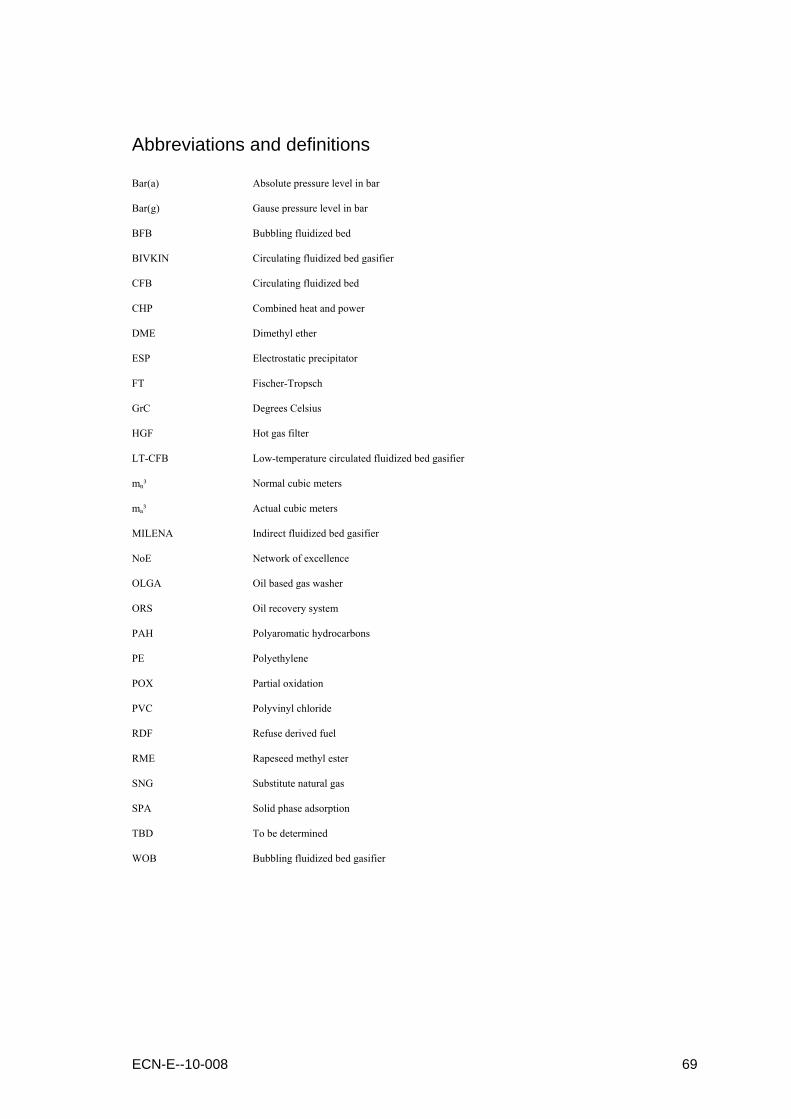
Abbreviations and definitions
Bar(a) Absolute pressure level in bar
Bar(g) Gause pressure level in bar
BFB Bubbling fluidized bed
BIVKIN Circulating fluidized bed gasifier
CFB Circulating fluidized bed
CHP Combined heat and power
DME Dimethyl ether
ESP Electrostatic precipitator
FT Fischer-Tropsch
GrC Degrees Celsius
HGF Hot gas filter
LT-CFB Low-temperature circulated fluidized bed gasifier
mn³ Normal cubic meters
ma³ Actual cubic meters
MILENA Indirect fluidized bed gasifier
NoE Network of excellence
OLGA Oil based gas washer
ORS Oil recovery system
PAH Polyaromatic hydrocarbons
PE Polyethylene
POX Partial oxidation
PVC Polyvinyl chloride
RDF Refuse derived fuel
RME Rapeseed methyl ester
SNG Substitute natural gas
SPA Solid phase adsorption
TBD To be determined
WOB Bubbling fluidized bed gasifier
ECN-E--10-008 69

70 ECN-E--10-008
ECN-E--10-008 71
References
[1] Mozaffarian, H., Zwart, R.W.R., Boerrigter, H., Deurwaarder, E., and Kersten, S.R.A., “Green gas as SNG (synthetic natural gas); a renewable fuel with conventional quality”, Science in thermal and chemical conversion, Vancouver, Canada, ECN-RX-04-085, 2008, 17 p.
[2] Van der Meijden, C.M., Veringa, H.J., Van der Drift, A., and Vreugdenhil, B.J., “The 800 kWth
allothermal biomass gasifier MILENA”, Presented at 16th European biomass conference & exhibition, Valencia, Spain, ECN-M-08-083, 2008, 6 p.
[3] Van der Drift, A., Van der Meijden, C.M., and Boerrigter, H., “MILENA gasification technology for
high efficient SNG production from biomass”, Presented at 14th European biomass conference & exhibition, Paris, France, ECN-RX-05-183, 2005, 3 p.
[4] Van der Drift, A., Van der Meijden, C.M., and Strating-Ytsma, S.D., “HIgher carbon conversion in
CFB biomass gasifiers” (in Dutch), ECN, ECN-C-03-053, 2003, 44 p. [5] Vreugdenhil, B.J., and Zwart, R.W.R., “Tar formation in pyrolysis and gasification”,
ECN-E-08-087, 2009, pp. 324-335 [6] Thersites: the ECN tar dew point site http://www.thersites.nl [7] Van Paasen, S.V.B., Cieplik, M.K., and Phokawat, N.P., “Gasification of non-woody biomass –
Economic and technical perspectives of chlorine and sulphur removal from product gas”, ECN, ECN-C-06-032, 2006, 54 p.
[8] Visser, H.J.M., Zwart, R.W.R., Könemann, H.W.J., Bos, A., and Kuipers, J., “RDF-gasification part
1: characterizing the use of RDF as fuel and solving the tar problem by an in-depth laboratory study”, ECN, Presented at the 2nd international symposium on energy from biomass and waste in Venice, 2008
[9] Stoholm, P., Nielsen, R.G., Richardt, K., Sander, B., Henriksen, U.B., Qvale, E.B., Gurbuz, S., Brix,
M., Hansen, M.W., and Wolff, L., “The Low Temperature CFB Gasifier : Latest 50 KW Test Results and New 500 KW Plant”, Presented at Grafica Lito, Florence, Italy, 2004
[10] Stoholm, P., Nielsen, R.G., Sarbæk, L., Tobiasen, L., Henriksen, U.B., Fock, M.W., Richardt, K.,
Sander, B., and Wolff, L., “The Low Temperature CFB Gasifier - Further Test Results and Possible Applications”, Presented at: European Biomass Conference, Amsterdam, 2002
[11] Stoholm, P., Nielsen, R.G., Nygaard, H., Tobiasen, L., Fock, M.W., Richardt, K., and Henriksen,
U.B., “Low temperature CFB gasifier conceptual ideas, applications and first test results”, Presented at World Conference and Exhibition on Biomass for Energy and Industry, Seville, Spain, 2000
[12] Nielsen, R.G., Stoholm, P., Nielsen, M.B., Nørholm, N., Antonsen, S., Sander, B., Krogh, J.,
Henriksen, U.B., and Qvale, E.B., “The LT-CFB gasifier : First test results from the 500 kW test plant”, Presented at Biomass for energy, industry and climate protection, 14th European conference and exhibition, Paris, 2005
[13] Zwart, R.W.R., Van der Drift, A., Bos, A., Visser, H.J.M., Cieplik, M.K., and Könemann, H.W.J.,
“Oil-based gas washing – flexible tar removal for high-efficient production of clean heat and power as well as sustainable fuels and chemicals”, Environmental Progress & Sustainable Energy, vol. 28, no. 3, 2009, 12 p.
[14] Rabou, L.P.L.M., Zwart, R.W.R., Vreugdenhil, B.J., and Bos, A., “Tar in biomass producer gas, the
Energy research Centre of the Netherlands (ECN) experience: an enduring challenge”, Energy & Fuels, vol. 23, pp. 6189-6198
72 ECN-E--10-008
[15] Könemann, H.W.J., “OLGA tar removal technology”, Technical information paper, 2009, 30 p. [16] Verhoeff, F., Rabou, L.P.L.M., Van Paasen, S.V.B., Emmen, R., Buwalda, R.A., Klein
Teeselink, H., “Preparation bioCHP: 1000 hours duration test” (in Dutch), ECN, ECN-E-06-044, 2006, 69 p.
[17] Simell, P., Ståhlberg, P., Kurkela, E., Albrecht, J., Deutsch, S., and Sjöström, K., “Provisional
protocol for the sampling and analysis of tar and particulates in the gas from large-scale biomass gasifiers”, Biomass & Bioenergy, vol. 18, no. 3, 2000, pp. 19-38
[18] Abu El-Ruba, Z., Bramer, E.A., and Brem, G., “Experimental comparison of biomass chars with
other catalysts for tar reduction”, Fuel, vol. 87, issues 10-11, 2008, pp. 2243-2252 [19] Kiel, J.H.A., Van Paasen, S.V.B., Neeft, J.P.A., Devi, L., Ptasinski, K.J., Janssen, F.J.J.G.,
Meijer, R., Berends, R.H., Temmink, H.M.G., Brem, G., Padban, N., and Bramer, E.A., “Primary measures to reduce tar formation in fluidized-bed biomass gasifiers”, ECN, ECN-C-04-014, 2004, 108 p.
[20] Graham, R.G., and Bergougnou, M.A., “Fast pyrolysis of biomass”, Journal of Analytical and
Applied Catalysis, vol. 6, 1984, pp. 93-135 [21] Lievens, C., Yperman, J., Cornelissen, T., and Carleer, R., “Study of the potential valorisation of
heavy metal contaminated biomass via phytoremediation by fast pyrolysis – Part II: Characterisation of the liquid and gaseous fraction as function of the temperature”, Fuel, vol. 87, 2008, pp. 1906-1916
[22] Bos, A., Zwart, R.W.R., “Method and system for gasifying biomass”, ECN, Dutch patent application
2003547, September 25th 2009 [23] 3MTM documentation http://www.3m.com/market/industrial/ceramics/materials/filter_product.html [24] Brandt, P., Larsen, E., Henriksen, U. ”High Tar Reduction in a Two-Stage Gasifier”. Energy &
Fuels 2000, 14, p. 816-819. [25] Ahrenfeldt, J., Henriksen, U., Jensen, T. K., Gøbel, B., Wiese, L., Kather, A., Egsgaard, H.
”Validation of a Continuous Combined Heat and Power (CHP) Operation of a Two-Stage Biomass Gasifier”. Energy & Fuels, paper id. ef0503616, 2006.
[26] Brandt, P., Henriksen, U. “Decomposition of tar in pyrolysis gas by partial oxidation and thermal
cracking. Part 2”. In proceedings of the conference: 10th European Conference and Technology Exhibition: Biomass for Energy and Industry". Würzburg. Germany. 8.11. June 1998. pp. 1616-1618
[27] Ledesma. E.B., Kalish, M.A., Nelson, P.F., Wornat, M.J., and Mackie, J.C., “Formation and fate of
PAH during the pyrolysis and fuel-rich combustion of coal primary tar”, Fuel 79 (2000), pp. 1801-1814.
[28] Henriksen, U., Ahrenfeldt, J., Jensen, T.K., Gøbel, B., Bentzen, J. B., Hindsgaul C., and Sørensen,
L.H., “The Design, Construction and Operation of a 75 kW Two-Stage Gasifier”. Energy Vol. 31, Issues 10-11, 2006. pp. 1542-1553.
[29] Van Paasen, S.V.B., Kiel, J.H.A., Neeft, J.P.A., Knoef, H.A.M., Buffinga, G.J., Zielke, U.,
Sjöström, K., Brage, C., Hasler, P., Simell, P.A., Suomalainen, M., Dorrington, M.A., and Thomas, L., “Guideline for sampling and analysis of tar and particles in biomass producer gases – final report documenting the guideline, R&D work and dissemination”, ECN-C-02-090, ECN, Petten, the Netherlands, 2002.

ECN-E--10-008 73
[30] Fagernäs, L., Johansson, A., Wilén, C., Sipilä, K., Mäkinen, T., Helynen, S., Daugherty, E., Den
Uil, H., Vehlow, J., Kåberger, T., and Rogulska, M., “Bioenergy in Europe – Opportunities and barriers”, VTT Research notes 2352, VTT, Espoo, 2006, 118 p.
[31] Jungmeier, G., Mäkinen, T., Peck, P., Plepys, A., Pucker, J., Wilén, C., and Zwart, R., “Prospects for
the production and use of renewable substitute natural gas from biomass”, NoE Bioenergy JER 2.2 final report, SES6-CT-2003-502788, 2009, 64 p.
[32] Thornley, P., and Prins, W., “Non-technical barriers”, published in “Thermal biomass conversion”,
edited by Bridgwater, A.V., Hofbauer, H., and Van Loo, S., CPL Press, 2009, pp. 323-353 [33] European Parliament, “Promotion of the use of energy from renewable sources”, European
Parliament legislative resolution P6_TA-PROV(2008)0609, 2008, 76 p.