Embed Size (px)
Citation preview
DESIGN RULES
FOR DOWN DRAFT WOOD GASIFIERS
A SHORT REVIEW
prepared by dr.ir. Jan Venselaar
project JTA-9A - Research Development1
at the Institut Teknologi Bandung, Indonesia
August 1982
This a basic version as preparation for a paper which has never been published2.
The information is used in other reports the Indonesian and Dutch JTA team members have been involved, in particular the FAO report on Wood Gas as Engine Fuel, report M38, 1986.
l. Introduction During the already long existence of gasifiers, many quite different designs have been proposed and actually used. In essence the design is a simple one; a broad tubular reactor, a grate on which the fuel lays, one or more entrances for air, and an exit for the gas. Feed is coming in at top, the remaining ash (commonly) goes out at the bottom. The construction may be simple, the actual chemical and technical process is rather complicated, and still not completely understood. To have gasification occurring is easy, to execute it optimally, with high. efficiency and high gas quality is still difficult. The more so because basic principles are not completely clear, and never quantitatively described. Hence the many designs and different approaches. The controlling of the actual gasification process is still more an art than science. It is nevertheless tried to obtain some general rules which can guide the designing process. There are several typical grand designs for gasifiers, upstream, downstream, a combination of both "double fired", cross flow and fluidized! entrained bed gasifiers. The crucial factor is the flow of air, and produced gas. The solid material flows, normally, downwards.
1 JTA: Joint Technical Assistance, an international cooperation program of the Dutch Government in that period. 2 Notes in the text and in ‘ handwritten in the original’ scanned figures and tables indicate the discussion between the author and the late prof A.A.C.M. Beenackers (University Groningen) in particular. [..] indicates adapted text compared to the original

design rules for downdraft wood gasifiers
Dependent on the direction of this gas flow the relative position of the various zones: pyrolysis, oxidation, reduction is different, and therefore the sequence the gasfallows through these zones. (see fig 1).
Figure 1: Positioning of the different zones in the various types of gasifiers (1) pyrolysis (2) oxidation (3) reduction (NB fluidized bed gasifier is seen as not realistic for biomass) When using tar-free fuels, as cokes and charcoal, all types are feasible. The pyrolysis zone is of no consequence. For tar-producing fuels as [anthracite (removed because not suitable for this type of gasification)] brown coal, wood, peat and other biomass, that place of the pyrolysis zone is all important. The tar containing gas produced in that zone, should
J. Venselaar review 1982, JTA-9a project Bandung Indonesia Page 2 of 24
design rules for downdraft wood gasifiers
thereafter pass completely through a much hotter zone, viz. the oxidation zone, to minimize tar content. The downstream type of gasifier (together with its variation: the double fired of course) is the only possible in that case. For wood it is indeed the only encountered one, as well for stationary energy production as for traction purposes.
2. Design criteria Especially during the twenties, thirties of this century and the last war, gasification of wood and other biomass was strongly developed. Many commercial designs were available. We have tried now to establish from the available data in the old literature the parameters and their values necessary for design of a down draft wood gasifier of a certain capacity. We assume that these apparatuses, which were actually sold and used, performed to a certain standard, with regard to efficiency and gas quality. One, recent work was used, the more theoretically inclined dissertation of Groeneveld (1), to have some comparison between empirically and theoretically found values. The main criteria for a well functioning gasifier are: • high heating value of the gas, meaning high content of H2 and C02 ([3500 -] 5000
kJ/Nm3 seems quite good with 10 - 15 [30] % moisture in feedstock). • low content of tar, commonly a value of 0.5 g.Nm-3 dry gas is given, but values of 0.2
are preferable. • thorough burn-out of the carbon (>95%), which implies a high efficiency of the
process. (70-75% should be attainable) • unhampered down flow of the feed. • low pressure drop. • [good variable load-following characteristics] The relevant parameters for design are: • diameter of the constriction (the so-called throat), often applied below the oxidation
zone. • diameter of the tube, the reaction vessel itself. • length of the reduction zone. • place of air inlet(s). • surface area of air inlet(s)/velocity of entering air. • [throat angle]
J. Venselaar review 1982, JTA-9a project Bandung Indonesia Page 3 of 24
design rules for downdraft wood gasifiers
In general one can say that available data are difficult to systematize. It is not certain furthermore, that designs produced are in fact the optimal ones. And it is quite possible that quite different solutions to the same problem apply. It should be noted that this review concerns down draft gasifiers tested with European types of wood, in small blocks of 3-5 x 6-8 cm. Size of the feed is however thought critical (see Groeneveld (1)).
3. Tube and throat diameters The reactions in the various phases of the gasification process have specific, limited velocities. Residence time in each part of the gasifier is therefore a fundamental criterion to determine size of the various zones. Real residence time is however a difficult to establish entity. Not only are the, volume-, flows of gas and solid changing through the gasifier, the extent and height of a zone is controlled by various, interdependent factors. They are dependent of heat generated and used in the various phases; the convection and conduction possibilities; the way the gasses, and sometimes the solids too, are forced to flow. As main factor for determining the right circumstances for the process is normally taken the cross-section of the apparatus. That results in a flow per surface area for the different sections which is assumed to be determining for the processes. As critical value is then given the relative flow at maximal (sometimes said to the optimal) load, (in kg/m2.h for the solid or m/sec for the gas, the latter calculated at 0°C and for empty apparatus).
Residence time in the drying and pyrolysis zone should be such long that charcoal is formed which is completely free from volatiles. In the burning/oxidation zone all gas should be burned completely, which is a fast reaction. Residence time should be short so that charcoal is not combusted too much.
In the reduction zone the residence time of the gas should be such that a favorable equilibrium is reached. A too short time would result in unreacted carbon and gasses, a too long time, at low temperature, would influence the equilibrium adversely. Although the latter is often disputed, because the rather slow reaction velocities at such low temperatures. Besides total residence time, calculated for the total volume of a zone, the part of each zone where the bulk of the reaction takes place is important. The actual burning zone is rather thin. After a short distance the oxygen from the air is used up. The last pyrolysis step and the reduction will proceed very fast close to this oxidation zone. Both reactions will be therefore finished for larger part a few particle diameters away larger part a few [particle diameters] away from that zone only.
J. Venselaar review 1982, JTA-9a project Bandung Indonesia Page 4 of 24
design rules for downdraft wood gasifiers
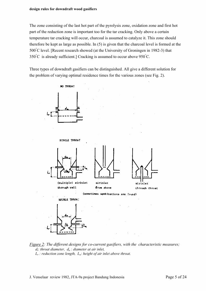
The zone consisting of the last hot part of the pyrolysis zone, oxidation zone and first hot part of the reduction zone is important too for the tar cracking. Only above a certain temperature tar cracking will occur, charcoal is assumed to catalyze it. This zone should therefore be kept as large as possible. In (5) is given that the charcoal level is formed at the 500°C level. [Recent research showed (at the University of Groningen in 1982-3) that 350°C is already sufficient.] Cracking is assumed to occur above 950°C. Three types of downdraft gasifiers can be distinguished. All give a different solution for the problem of varying optimal residence times for the various zones (see Fig. 2).
Figure 2: The different designs for co-current gasifiers, with the characteristic measures; dt: throat diameter, da : diameter at air inlet, Lr : reduction zone length, La: height of air inlet above throat.
J. Venselaar review 1982, JTA-9a project Bandung Indonesia Page 5 of 24
design rules for downdraft wood gasifiers
• Plain tube like apparatuses, without constriction. Residence times are determined only by the flow velocity of gas and solid. Height of the hot charcoal bed is often regulated through multiple rows of air inlets. These types, commonly heavily isolated, are used for stationary purposes only, with a not very variable load.
• A tube with a constriction (throat) just under the burning zone. Gas and solid flow have there a much higher flow velocity. The hot zone is more concentrated. It is extended through influencing the gas flow (circulation) by the form of throat and place of the airinlets.
• Apparatuses with, apparently, two constrictions (double throat). The first serves the same purpose as mentioned above. The second increases gas and solid flow in the reduction zone even more. After that, it is spread out again over the whole tube diameter. The hot gasses are possible by this more efficiently used. The systems is said to be better apt for a variable load, as encountered when using in traction.
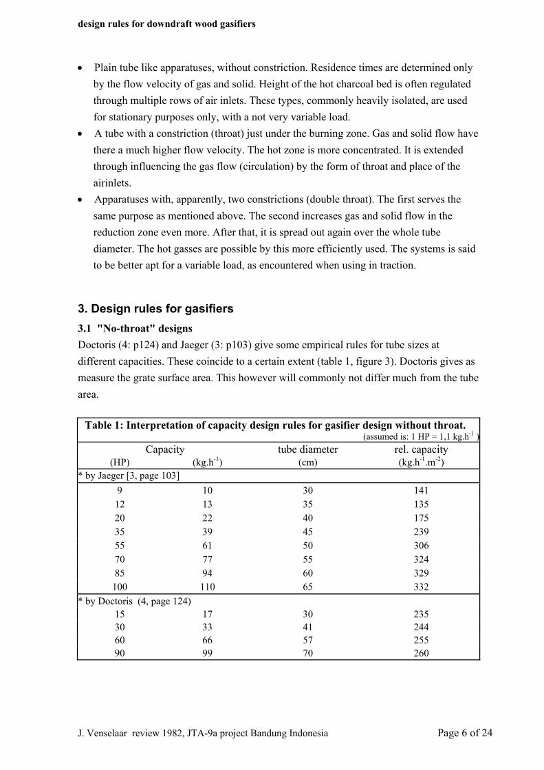
3. Design rules for gasifiers 3.1 "No-throat" designs Doctoris (4: p124) and Jaeger (3: p103) give some empirical rules for tube sizes at different capacities. These coincide to a certain extent (table 1, figure 3). Doctoris gives as measure the grate surface area. This however will commonly not differ much from the tube area.
Table 1: Interpretation of capacity design rules for gasifier design without throat. (assumed is: 1 HP = 1,1 kg.h-1 )
Capacity tube diameter rel. capacity (HP) (kg.h-1) (cm) (kg.h-1.m-2)
* by Jaeger [3, page 103] 9 10 30 141
12 13 35 135 20 22 40 175 35 39 45 239 55 61 50 306 70 77 55 324 85 94 60 329
100 110 65 332 * by Doctoris (4, page 124)
15 17 30 235 30 33 41 244 60 66 57 255 90 99 70 260
J. Venselaar review 1982, JTA-9a project Bandung Indonesia Page 6 of 24
design rules for downdraft wood gasifiers
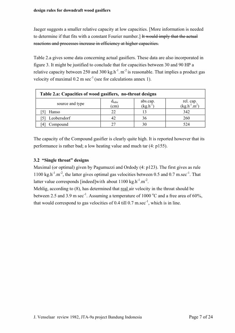
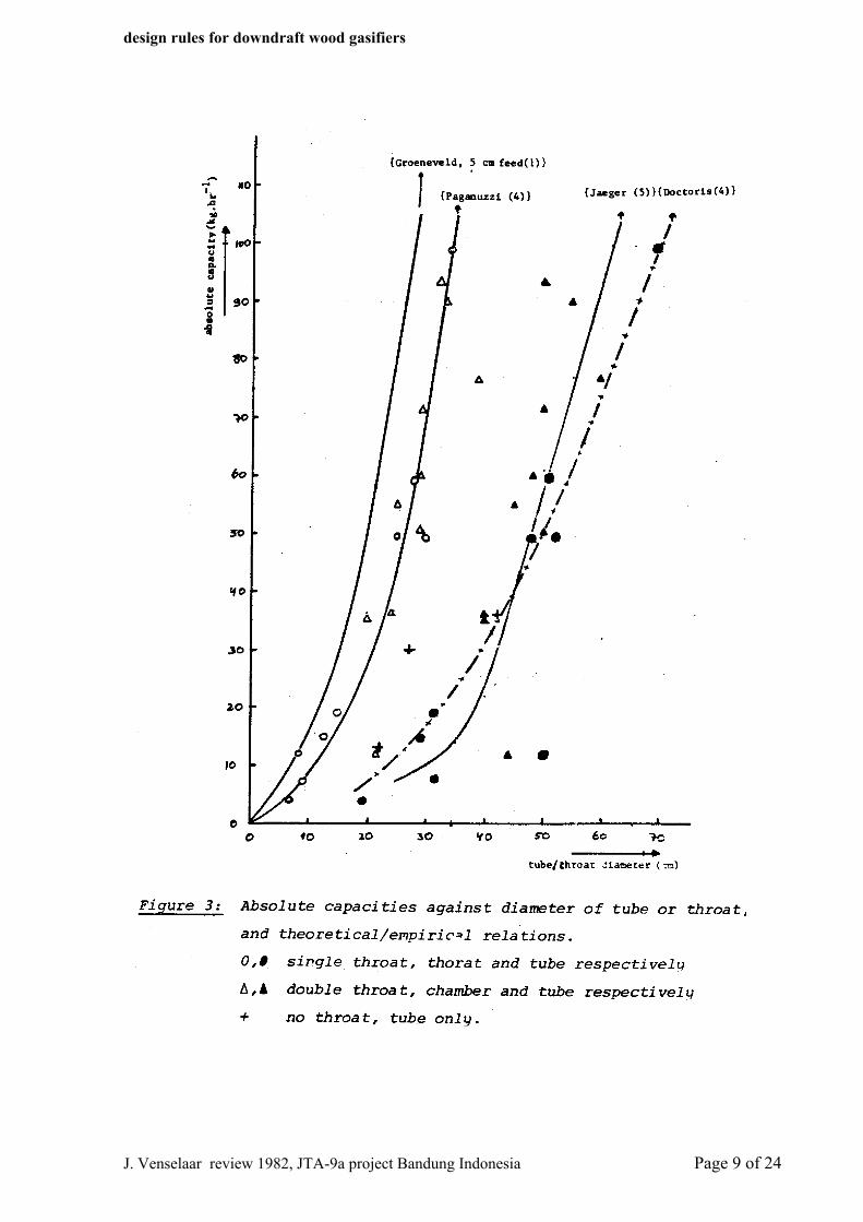
Jaeger suggests a smaller relative capacity at low capacities. [More information is needed to determine if that fits with a constant Fourier number.] It would imply that the actual reactions and processes increase in efficiency at higher capacities. Table 2.a gives some data concerning actual gasifiers. These data are also incorporated in figure 3. It might be justified to conclude that for capacities between 30 and 90 HP a relative capacity between 250 and 300 kg.h-1. m-2 is reasonable. That implies a product gas velocity of maximal 0.2 m sec-1 (see for calculations annex 1).
Table 2.a: Capacities of wood gasifiers, no-throat designs
source and type dtube (cm)
abs.cap. (kg.h-1)
rel. cap. (kg.h-1.m2)
[5] Hanso 22 13 342 [5] Leobersdorf 42 36 260 [4] Compound 27 30 524
The capacity of the Compound gasifier is clearly quite high. It is reported however that its performance is rather bad; a low heating value and much tar (4: p155). 3.2 “Single throat” designs Maximal (or optimal) given by Pagumuzzi and Ordody (4: p123). The first gives as rule 1100 kg.h-1.m-2, the latter gives optimal gas velocities between 0.5 and 0.7 m.sec-1. That latter value corresponds [indeed]with about 1100 kg.h-1.m-2.
Mehlig, according to (8), has determined that real air velocity in the throat should be between 2.5 and 3.9 m sec-1. Assuming a temperature of 1000 oC and a free area of 60%, that would correspond to gas velocities of 0.4 till 0.7 m.sec-1, which is in line.
J. Venselaar review 1982, JTA-9a project Bandung Indonesia Page 7 of 24
design rules for downdraft wood gasifiers
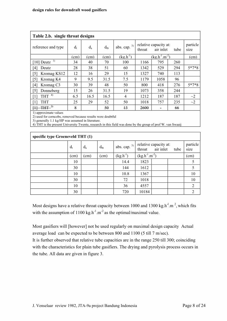
Table 2.b. single throat designs
reference and type dt da dtb abs. cap. 3) relative capacity at: throat air inlet tube
particle size
(cm) (cm) (cm) (kg.h-1) (kg.h-1.m-2) (cm)[10] Deutz 1) 34 40 70 100 1166 795 260 [4] Deutz 28 38 51 60 1342 529 294 5*7*8[5] Kromag KS12 12 16 29 15 1327 740 113 [5] Kromag K4 9 9.5 31.5 7.5 1179 1058 96 [4] Kromag C3 30 39 48 50 800 418 276 5*7*8[5] Donneberg 15 26 31.5 19 1073 358 244 [1] THT 4) 6.5 16.5 16.5 4 1212 187 187 ~2 [1] THT 25 29 52 50 1018 757 235 ~2 [1] THT 2) 8 50 13 2600 - 66 1) approximate values 2) used for corncobs, removed because results were doubtful 3) generally 1.1 kg/HP was assumed in literature. 4) THT is the present University Twente, research in this field was done by the group of prof W. van Swaaij specific type Groeneveld THT (1)
dt da dtb abs. cap. 3) relative capacity at: throat air inlet tube
particle size
(cm) (cm) (cm) (kg.h-1) (kg.h-1.m-2) (cm) 10 14.4 1823 5 30 144 1612 5 10 10.8 1367 10 30 72 1018 10 10 36 4557 2 30 720 10184 2
Most designs have a relative throat capacity between 1000 and 1300 kg.h-l.m 2, which fits with the assumption of 1100 kg.h-1.m-2 as the optimal/maximal value. Most gasifiers will [however] not be used regularly on maximal design capacity Actual average load can be expected to be between 800 and 1100 (5 till 7 m/sec). It is further observed that relative tube capacities are in the range 250 till 300; coinciding with the characteristics for plain tube gasifiers. The drying and pyrolysis process occurs in the tube. All data are given in figure 3.
J. Venselaar review 1982, JTA-9a project Bandung Indonesia Page 8 of 24
design rules for downdraft wood gasifiers
J. Venselaar review 1982, JTA-9a project Bandung Indonesia Page 9 of 24
design rules for downdraft wood gasifiers
The burning zone is important. It [Throat diameter at air inlet] cannot be too large. Otherwise cold spots would occur. It was thought therefore that relative capacity at that place, at a diameter commonly larger than the throat, would have a clear relation with absolute capacity too. As follows from table 2.b., that appears not to be the case. The burning and heat distribution is not so much dependent on the solid flow, as on the air flow and air distribution. Groeneveld (1: p58) proposes that the determining factor for maximal load is residence time of the fuel in the pyrolysis zone. That should be larger than the, Fourier, time for heating up. The height of the pyrolysis zone is taken as three particle diameters, its diameter that of the throat. A maximal load can be calculated for different size of the fuel particles. The results are given in table 2.b. too. That relation for 5 cm blocks of wood is given in figure 3. That seems about 75% higher than most actual capacities, closely fitted by Paganuzzi's relation. That can be an indication that complete devolatilization still needs a considerable time after complete heating up. Furthermore, in practice particle diameters are less precisely defined, and not uncommonly, larger. 3.3 “Double throat” designs (Imbert) From design rules ((3: p130) and (4: p198)) and actual designs it is clear that these Imbert-type gasifiers have a much higher relative throat capacity than previous described designs. They have an average of 4100 kg.h-l.m-2. This is corresponding with (9), where only this type of gasifier is described, which gives as maximal value 0.9 Nm3.h-l.cm-2 (about 2.5 m.sec-l or 3900 kg.h-l.m-2 ). The actual apparatuses worked at lower loads (table 2.c.). The relative capacities at the "first throat" (also called (burning) chamber) come in fact close to those for single throat designs, when we look into the empirical rules. Relative tube capacities are higher, but fit better for the tested apparatuses. The Semmler-Vedder gasifier is clearly designed for a much higher load than is proposed. Test results (5) indicate that already at slightly lower loads gas quality rapidly decreases.
J. Venselaar review 1982, JTA-9a project Bandung Indonesia Page 10 of 24
design rules for downdraft wood gasifiers
Table 2.c. Double throat designs
dt (cm)
da (cm)
dtb (cm)
abs.cap. 2)
(kg.h-1)
relative capacity at throat / chamber / tube
(kg.h_l.m_2) [4] Imbert 1) 4)
15 30 50 50 2824 707 255 [11] Berliet 20 38 60 77 2452 680 272 [5] Semmler 15 21 44 12 682 347 79 empirical rules derived for Imbert type gasifiers 3) [3] 12 24 40 36 3186 796 286 15 29 48 60 3390 922 332 16 33 55 90 4478 1053 379 18 36 60 120 4724 1178 424 21 42 70 144 4162 1040 374 24 48 80 180 3982 994 358[4] 10 20 40 35 4456 1104 278
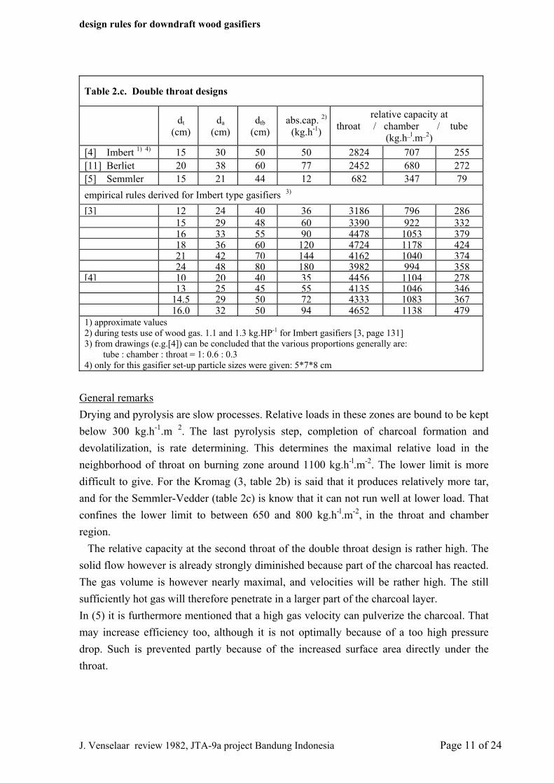
13 25 45 55 4135 1046 346 14.5 29 50 72 4333 1083 367 16.0 32 50 94 4652 1138 4791) approximate values 2) during tests use of wood gas. 1.1 and 1.3 kg.HP-1 for Imbert gasifiers [3, page 131] 3) from drawings (e.g.[4]) can be concluded that the various proportions generally are: tube : chamber : throat = 1: 0.6 : 0.3 4) only for this gasifier set-up particle sizes were given: 5*7*8 cm
General remarks Drying and pyrolysis are slow processes. Relative loads in these zones are bound to be kept below 300 kg.h-1.m 2. The last pyrolysis step, completion of charcoal formation and devolatilization, is rate determining. This determines the maximal relative load in the neighborhood of throat on burning zone around 1100 kg.h-l.m-2. The lower limit is more difficult to give. For the Kromag (3, table 2b) is said that it produces relatively more tar, and for the Semmler-Vedder (table 2c) is know that it can not run well at lower load. That confines the lower limit to between 650 and 800 kg.h-l.m-2, in the throat and chamber region. The relative capacity at the second throat of the double throat design is rather high. The solid flow however is already strongly diminished because part of the charcoal has reacted. The gas volume is however nearly maximal, and velocities will be rather high. The still sufficiently hot gas will therefore penetrate in a larger part of the charcoal layer. In (5) it is furthermore mentioned that a high gas velocity can pulverize the charcoal. That may increase efficiency too, although it is not optimally because of a too high pressure drop. Such is prevented partly because of the increased surface area directly under the throat.
J. Venselaar review 1982, JTA-9a project Bandung Indonesia Page 11 of 24
design rules for downdraft wood gasifiers
4. Height of the pyrolysis zone As is mentioned before maximal load of the gasifier is for a large part determined by the complete devolatilization of the charcoal formed (1). Furthermore, complete cracking of the tar is only possible when the hot charcoal zone is high enough (5). The height of the pyrolysis zone is the result of heat transport, by conduction, convection and radiation. Heat is generated in the burning zone, and part of the pyrolysis zone, where it is exothermic. In (5) is stated that volume of the charcoal zone (including reduction) should be so large that residence time of the gas is 1.75 sec (calculated on empty space at 0 oC). When calculated on tube diameter that would mean a height of 35 cm. Because of the constriction and narrower reduction zone that will be between 45 and 55 cm. That is about 10 till 15 cm above the burning zone/air inlet. That layer will be, together with a few cm at the top of the reduction zone, the actual hot zone where tar is cracked. In (4) is experimented with the position of the air inlet of a Deutz gasifier (central air inlet). A higher "glowing zone" (oxidation and reduction zone) improves quality. Till it is too high, because cold spots can occur when diameter is too large. A hot charcoal bed that is large enough is attainable only when relative good. That is commonly easier with feature that is sometimes encountered is a regulated "air leak" above the pyrolysis zone (e.g. (5) fig. 40, Danneberg gasifier) which appears to enlarge the hot zone by a little additional combustion. In the given example that tar content is still high, and charcoal level low, possibly because of rather insufficient insulation. The positioning of air inlets in rows above each other of course also extend the hot zone. This is common usage in the larger designs.
5. Height of the reduction zone The actual burning zone is small. The reduction zone starts at the height of the, lowest, air inlet. The length of the zone were the reduction actually takes place is determined by the progress of the, endothermic, reaction. When the temperature has decreased till 700°C, (or already earlier; in (9) at 900°C) the reaction has virtually come to a standstill. However completion and standstill of the reaction is not necessarily the same. Heat losses can occur and the reaction stops before completion. So a good insulation is needed. Preheating of the entering air with the reduction zone heat is therefore unprofitable. A too long reduction bed is not acceptable either. Not only because of too high pre-sure drop, but also because heat losses aggravate. Increasing the initial temperature, by larger flow of air, e.g. at higher loads, brings the reduction length down. However efficiency tends to decrease (1 en 9). An increased length
J. Venselaar review 1982, JTA-9a project Bandung Indonesia Page 12 of 24
design rules for downdraft wood gasifiers
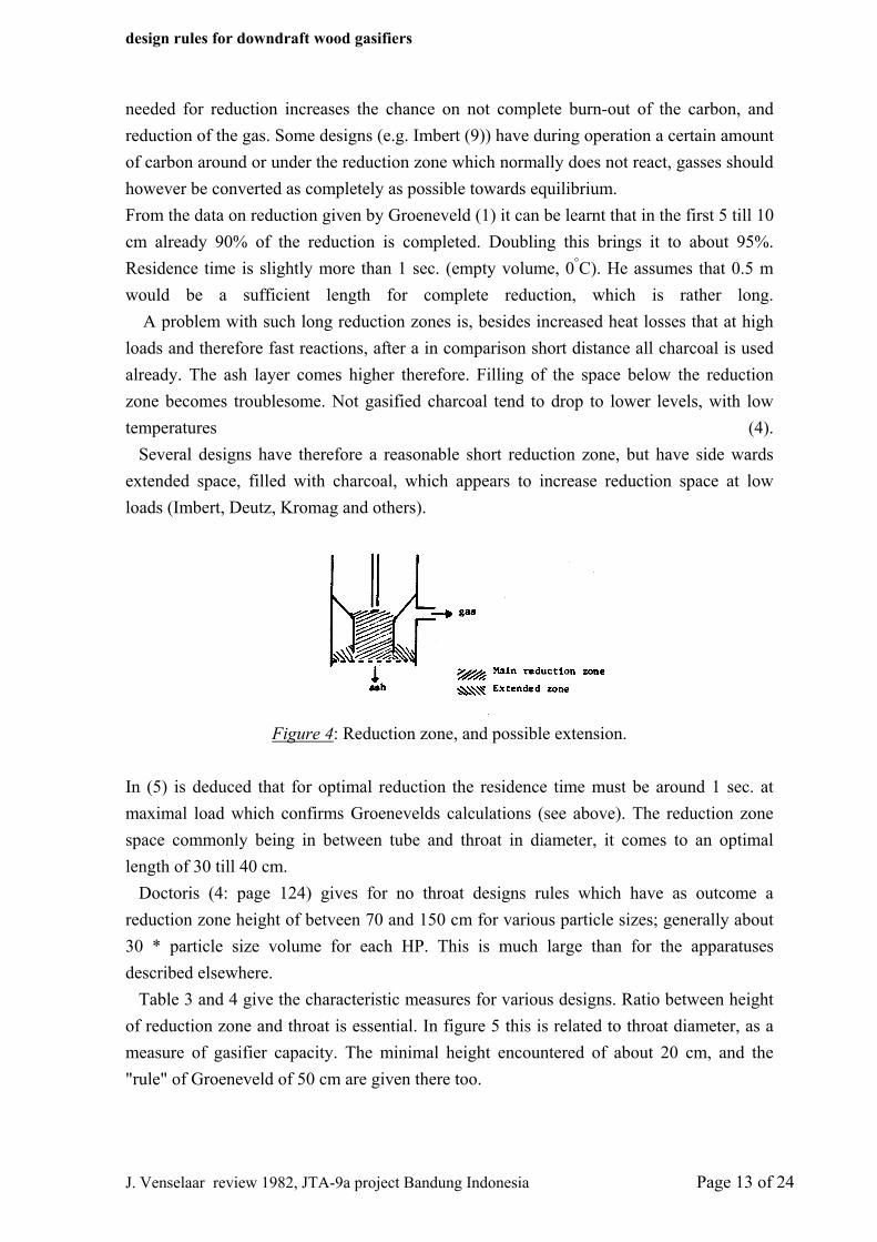
needed for reduction increases the chance on not complete burn-out of the carbon, and reduction of the gas. Some designs (e.g. Imbert (9)) have during operation a certain amount of carbon around or under the reduction zone which normally does not react, gasses should however be converted as completely as possible towards equilibrium. From the data on reduction given by Groeneveld (1) it can be learnt that in the first 5 till 10 cm already 90% of the reduction is completed. Doubling this brings it to about 95%. Residence time is slightly more than 1 sec. (empty volume, 0°C). He assumes that 0.5 m would be a sufficient length for complete reduction, which is rather long. A problem with such long reduction zones is, besides increased heat losses that at high loads and therefore fast reactions, after a in comparison short distance all charcoal is used already. The ash layer comes higher therefore. Filling of the space below the reduction zone becomes troublesome. Not gasified charcoal tend to drop to lower levels, with low temperatures (4). Several designs have therefore a reasonable short reduction zone, but have side wards extended space, filled with charcoal, which appears to increase reduction space at low loads (Imbert, Deutz, Kromag and others).
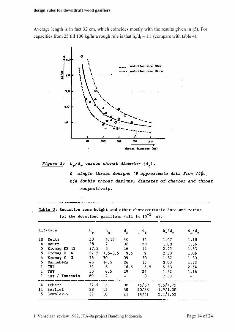
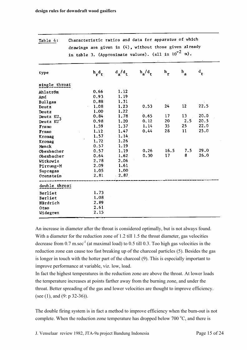
Figure 4: Reduction zone, and possible extension. In (5) is deduced that for optimal reduction the residence time must be around 1 sec. at maximal load which confirms Groenevelds calculations (see above). The reduction zone space commonly being in between tube and throat in diameter, it comes to an optimal length of 30 till 40 cm. Doctoris (4: page 124) gives for no throat designs rules which have as outcome a reduction zone height of betveen 70 and 150 cm for various particle sizes; generally about 30 * particle size volume for each HP. This is much large than for the apparatuses described elsewhere. Table 3 and 4 give the characteristic measures for various designs. Ratio between height of reduction zone and throat is essential. In figure 5 this is related to throat diameter, as a measure of gasifier capacity. The minimal height encountered of about 20 cm, and the "rule" of Groeneveld of 50 cm are given there too.
J. Venselaar review 1982, JTA-9a project Bandung Indonesia Page 13 of 24
design rules for downdraft wood gasifiers
Average length is in fact 32 cm, which coincides mostly with the results given in (5). For capacities from 25 till 100 kg/hr a rough rule is that hr/dt ~ 1.1 (compare with table 4).
J. Venselaar review 1982, JTA-9a project Bandung Indonesia Page 14 of 24
design rules for downdraft wood gasifiers
An increase in diameter after the throat is considered optimally, but is not always found. With a diameter for the reduction zone of 1.2 till 1.5 the throat diameter, gas velocities decrease from 0.7 m.sec-l (at maximal load) to 0.5 till 0.3. Too high gas velocities in the reduction zone can cause too fast breaking up of the charcoal particles (5). Besides the gas is longer in touch with the hotter part of the charcoal (9). This is especially important to improve performance at variable, viz. low, load. In fact the highest temperatures in the reduction zone are above the throat. At lower loads the temperature increases at points farther away from the burning zone, and under the throat. Better spreading of the gas and lower velocities are thought to improve efficiency. (see (1), and (9: p 32-36)). The double firing system is in fact a method to improve efficiency when the bum-out is not complete. When the reduction zone temperature has dropped below 700 oC, and there is
J. Venselaar review 1982, JTA-9a project Bandung Indonesia Page 15 of 24
design rules for downdraft wood gasifiers
still carbon left a fresh injection of air from below does increase temperature and forms more H2O and CO2 but these will normally not be depleted. Reduction can continue again. Air is introduced below the gas exit. That is to prevent as much as possible burning of the already produced gases. Actually one tries to create an updraft charcoal gasifier. It would suggest that co-introduction of water is favorable. This setup is found, for instance, in the older Deutz designs (Z) and the Brandt generator (4).
6. Position of the air inlet(s) The burning zone, positioned directly at the site(s) of the air inlet, is a rather thin zone. Real burning, of the pyrolysis gasses, is taking place only in an area close to the actual inlets. Oxygen is depleted already after about two particle diameters (1). The hot zone is extended through penetration of the hot gasses, driven by the power of the entering air. The extension of the hot zone must be good, meaning the complete area at the airin1et height should have the maximal attained temperature. The main reasons for this are: - at cold spots tar cracking is not sufficient, so tar can pass through to below and end up
in the produced gas. - at such colder places the above and under laying areas stay colder too, with the result a
non-homogeneous progress of the reactions over the reactor.
According to Groeneveld (1) the pyrolysis - and burnt gasses are taken up in a circulation caused by the stream of air. By this they enter again after circulation the hottest parts near the inlets. To optimize this circulation the air must not be able to travel directly downwards. Diameter should be not to large there, and the wall be inclined. The former will also decrease chances for cold spots to occur.
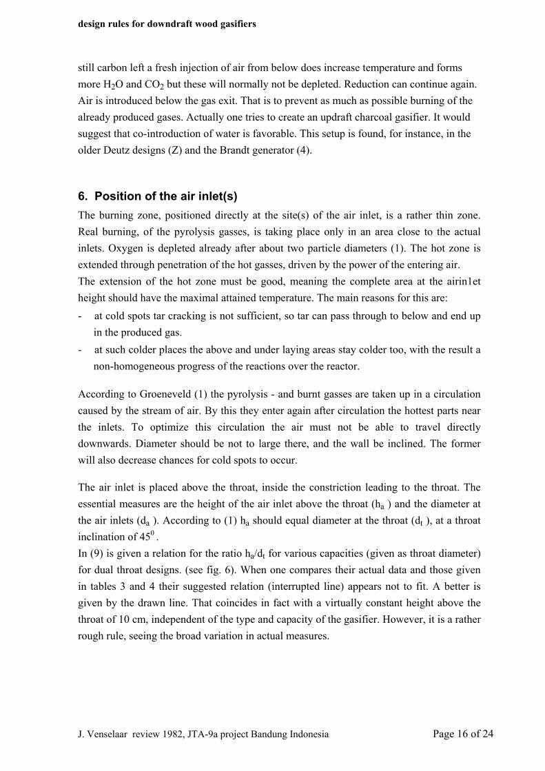
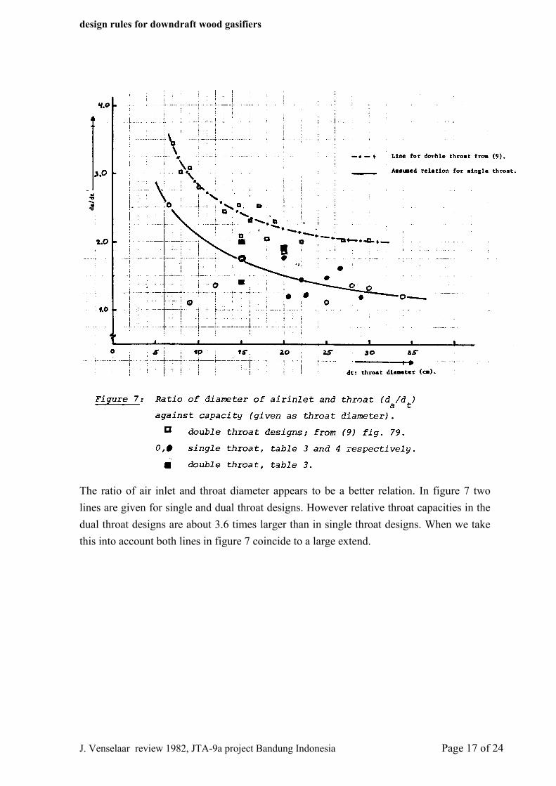
The air inlet is placed above the throat, inside the constriction leading to the throat. The essential measures are the height of the air inlet above the throat (ha ) and the diameter at the air inlets (da ). According to (1) ha should equal diameter at the throat (dt ), at a throat inclination of 450 . In (9) is given a relation for the ratio ha/dt for various capacities (given as throat diameter) for dual throat designs. (see fig. 6). When one compares their actual data and those given in tables 3 and 4 their suggested relation (interrupted line) appears not to fit. A better is given by the drawn line. That coincides in fact with a virtually constant height above the throat of 10 cm, independent of the type and capacity of the gasifier. However, it is a rather rough rule, seeing the broad variation in actual measures.
J. Venselaar review 1982, JTA-9a project Bandung Indonesia Page 16 of 24
design rules for downdraft wood gasifiers
The ratio of air inlet and throat diameter appears to be a better relation. In figure 7 two lines are given for single and dual throat designs. However relative throat capacities in the dual throat designs are about 3.6 times larger than in single throat designs. When we take this into account both lines in figure 7 coincide to a large extend.
J. Venselaar review 1982, JTA-9a project Bandung Indonesia Page 17 of 24
design rules for downdraft wood gasifiers
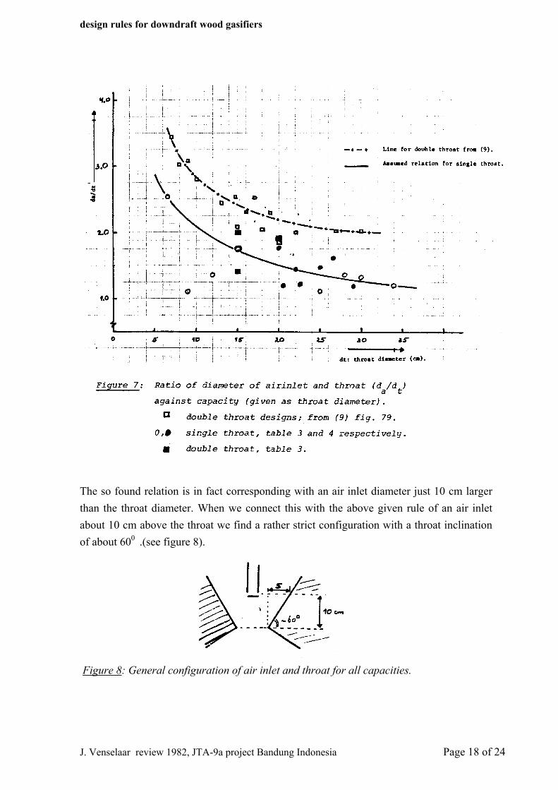
The so found relation is in fact corresponding with an air inlet diameter just 10 cm larger than the throat diameter. When we connect this with the above given rule of an air inlet about 10 cm above the throat we find a rather strict configuration with a throat inclination of about 600 .(see figure 8).
Figure 8: General configuration of air inlet and throat for all capacities.
J. Venselaar review 1982, JTA-9a project Bandung Indonesia Page 18 of 24
design rules for downdraft wood gasifiers
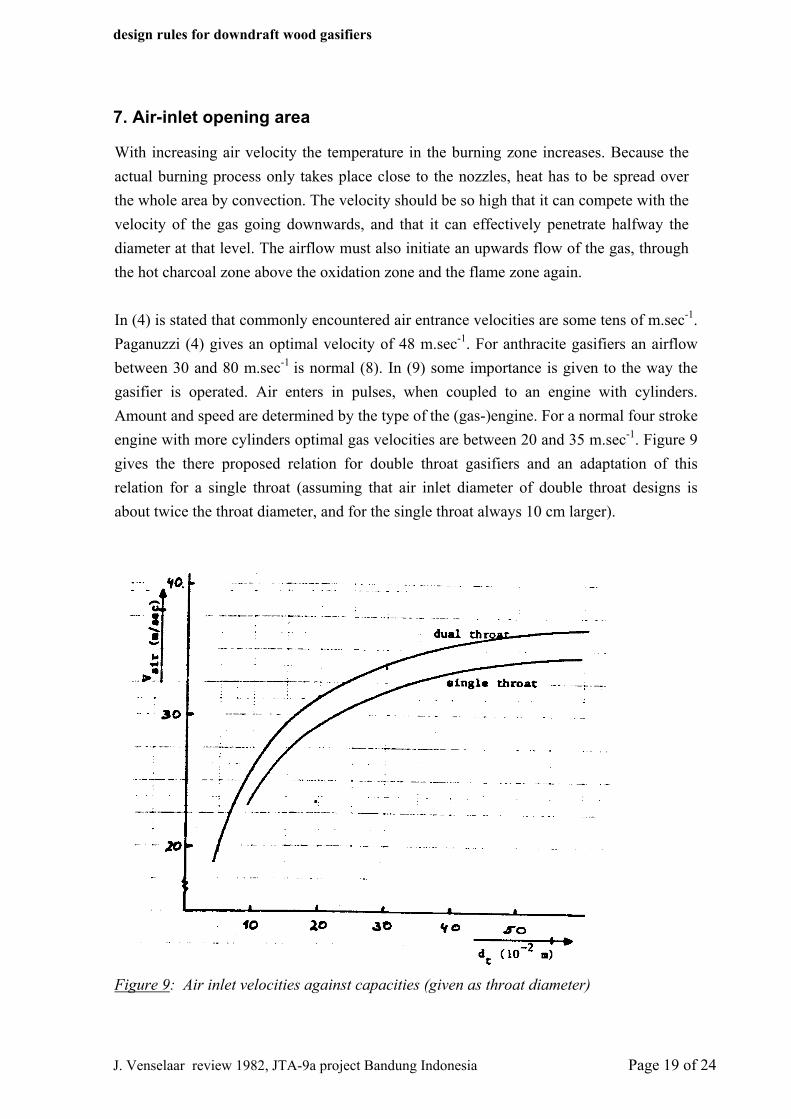
7. Air-inlet opening area
With increasing air velocity the temperature in the burning zone increases. Because the actual burning process only takes place close to the nozzles, heat has to be spread over the whole area by convection. The velocity should be so high that it can compete with the velocity of the gas going downwards, and that it can effectively penetrate halfway the diameter at that level. The airflow must also initiate an upwards flow of the gas, through the hot charcoal zone above the oxidation zone and the flame zone again. In (4) is stated that commonly encountered air entrance velocities are some tens of m.sec-1. Paganuzzi (4) gives an optimal velocity of 48 m.sec-1. For anthracite gasifiers an airflow between 30 and 80 m.sec-1 is normal (8). In (9) some importance is given to the way the gasifier is operated. Air enters in pulses, when coupled to an engine with cylinders. Amount and speed are determined by the type of the (gas-)engine. For a normal four stroke engine with more cylinders optimal gas velocities are between 20 and 35 m.sec-1. Figure 9 gives the there proposed relation for double throat gasifiers and an adaptation of this relation for a single throat (assuming that air inlet diameter of double throat designs is about twice the throat diameter, and for the single throat always 10 cm larger).
Figure 9: Air inlet velocities against capacities (given as throat diameter)
J. Venselaar review 1982, JTA-9a project Bandung Indonesia Page 19 of 24
design rules for downdraft wood gasifiers
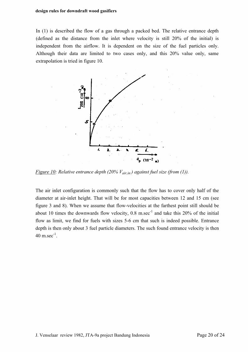
In (1) is described the flow of a gas through a packed bed. The relative entrance depth (defined as the distance from the inlet where velocity is still 20% of the initial) is independent from the airflow. It is dependent on the size of the fuel particles only. Although their data are limited to two cases only, and this 20% value only, same extrapolation is tried in figure 10.
Figure 10: Relative entrance depth (20% Vair,in ) against fuel size (from (1)).
The air inlet configuration is commonly such that the flow has to cover only half of the diameter at air-inlet height. That will be for most capacities between 12 and 15 cm (see figure 3 and 8). When we assume that flow-velocities at the farthest point still should be about 10 times the downwards flow velocity, 0.8 m.sec-1 and take this 20% of the initial flow as limit, we find for fuels with sizes 5-6 cm that such is indeed possible. Entrance depth is then only about 3 fuel particle diameters. The such found entrance velocity is then 40 m.sec-1.
J. Venselaar review 1982, JTA-9a project Bandung Indonesia Page 20 of 24
design rules for downdraft wood gasifiers
8 Air-inlet configuration Position and form of the air inlet should be such that the hot gas is distributed as equally as possible over the whole area. As is said before, tar-cracking is optimally when residence time in the hot charcoal zone is extended. Groeneveld (1) has obtained good results when he could establish a certain amount of circulation inside the pyrolysis zone. This does not only increase residence time in this zone but also extends it upwards because of stronger upwards convection of hot gasses. To obtain this recirculation position of the air inlet and inclination of the throat are critical (e.g. figure 8). In some designs the air inlet are pointed upwards, in a more or les ser angle, e.g. the designs with a central air inlet.
J. Venselaar review 1982, JTA-9a project Bandung Indonesia Page 21 of 24
design rules for downdraft wood gasifiers
9. Recapitulation [of main conclusions] Relative capacity
- maximal 250 - 300 kg.h-1.m-2 in tube ~ 1100 in throat (STD) or chamber (DTD) ~ 4000 in throat (DTD) (see figure 3) - minimal 650 - 800 kg.h-1.m-2 in throat (STD) or chamber (DTD) Charcoal layer - 10-20 cm, above airinlets: Reduction zone: - length: > 20 cm, mean 32 cm (see figure 5) - increase diameter after throat. Throat / air inlets:
- inclination of throat 450 - 600 - 10 cm above smallest constriction - diameter at air inlet: ~ 10 cm larger than constriction (STD), ~ 20 cm larger (DTD) (see figure 8).
Air velocity - 30 - 35 m.sec-1
- slightly pointed upwards. Important
- good isolation at hot charcoal zone, and reduction zone. - good distribution of the hot gas over the oxidation zone, no cold spots.
J. Venselaar review 1982, JTA-9a project Bandung Indonesia Page 22 of 24
design rules for downdraft wood gasifiers
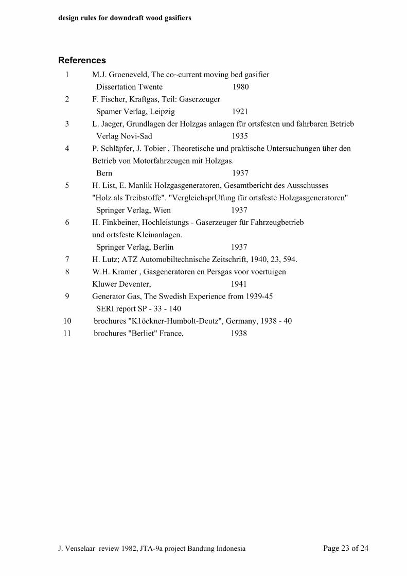
References 1 M.J. Groeneveld, The co~current moving bed gasifier Dissertation Twente 1980 2 F. Fischer, Kraftgas, Teil: Gaserzeuger Spamer Verlag, Leipzig 1921 3 L. Jaeger, Grundlagen der Holzgas anlagen für ortsfesten und fahrbaren Betrieb Verlag Novi-Sad 1935 4 P. Schläpfer, J. Tobier , Theoretische und praktische Untersuchungen über den Betrieb von Motorfahrzeugen mit Holzgas. Bern 1937 5 H. List, E. Manlik Holzgasgeneratoren, Gesamtbericht des Ausschusses "Holz als Treibstoffe". "VergleichsprUfung für ortsfeste Holzgasgeneratoren" Springer Verlag, Wien 1937 6 H. Finkbeiner, Hochleistungs - Gaserzeuger für Fahrzeugbetrieb und ortsfeste Kleinanlagen. Springer Verlag, Berlin 1937 7 H. Lutz; ATZ Automobiltechnische Zeitschrift, 1940, 23, 594. 8 W.H. Kramer , Gasgeneratoren en Persgas voor voertuigen Kluwer Deventer, 1941 9 Generator Gas, The Swedish Experience from 1939-45 SERI report SP - 33 - 140 10 brochures "K1öckner-Humbolt-Deutz", Germany, 1938 - 40 11 brochures "Berliet" France, 1938
J. Venselaar review 1982, JTA-9a project Bandung Indonesia Page 23 of 24
design rules for downdraft wood gasifiers
J. Venselaar review 1982, JTA-9a project Bandung Indonesia Page 24 of 24
(page 26) Annex I
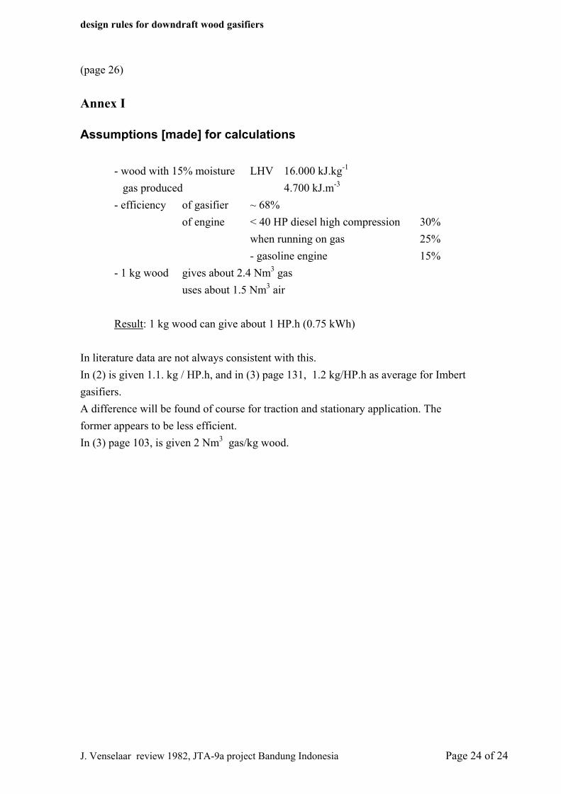
Assumptions [made] for calculations
- wood with 15% moisture LHV 16.000 kJ.kg-1 gas produced 4.700 kJ.m-3
- efficiency of gasifier ~ 68% of engine < 40 HP diesel high compression 30%
when running on gas 25% - gasoline engine 15%
- 1 kg wood gives about 2.4 Nm3 gas uses about 1.5 Nm3 air
Result: 1 kg wood can give about 1 HP.h (0.75 kWh)
In literature data are not always consistent with this. In (2) is given 1.1. kg / HP.h, and in (3) page 131, 1.2 kg/HP.h as average for Imbert gasifiers. A difference will be found of course for traction and stationary application. The former appears to be less efficient. In (3) page 103, is given 2 Nm3 gas/kg wood.