Embed Size (px)
Citation preview
1
Have you ever built an airplane and wished that
it held more fuel, or had a production tank that just
does not fit well or conform to the planes available
space? This is a common issue with jets-wanting to
carry more fuel or to add the option of a smoke system
in limited space. Most of the time is an odd-shaped
compartment). Why not build your own? This is a step-
by-step of how I built a custom smoke oil tank for my
C-ARF CT-114 Tutor. C-ARF uses a 40-50 oz tank
from another kit that fits in an area below the fuel tank.
This kept the smoke oil close to the center of gravity.
This is ideal but the tank just did not hold the
volume of smoke oil I wanted to carry. The option was
a commercial tank that held 64 oz but was a very heavy
plastic and still did not give me the volume I wanted.
The Jet Central variable speed smoke oil pump that I
am using to supply the 8-12 oz per min. of smoke oil to
the (2) 4mm stainless steel injectors that inject the oil
into the hot exhaust gas stream. These tubes exit at the
rear of the thrust tube outside of the jet’s tail. We will
build this tank in 3 phases, phase #1 making of the plug
of the custom tank. Phase #2, making the mold. Phase
#3 actually making the tank. I will add the suppliers’
website list at the end of this article. Now lets get
started building a custom fitted tank.
You will need a few items to get started; a
block of white foam, a hot wire or hand-saw, latex or
Nitrile gloves, laminating epoxy, fiberglass mat, fiber-
glass cloth in several weights (3 oz E glass and 5.7oz S
glass), polyester resin and hardener, Bondo polyester
filler, Duratec polyester primer, tooling gel coat, mold
release wax or PVA, or Pol-Ease 2300 release agent,
Dremel tool, paper towels, several different sandpaper
grits, (80, 120), and wet or dry in several grits from
120, 220, 400, 800, 1200, 1500 to 2000, 1/4 inch luan
plywood, Formica, 1 dozen 1-inch disposable paint
brushes, three or four 1 1/2 inch foam disposable
brushes, denatured alcohol and acetone.
The first thing that you need to do is figure out
where in the plane you want to fit a custom tank. Meas-
ure the area you want to put the tank in remembering to
check for any servo wires, wire routing, landing gear
bolts, screws, wing bolts, fuel and vent line routing.
When you measure don’t fit it tight but allow
about a 1/4 to 3/8 of an inch clearance of the foam to
allow for the plug’s layup material and Duratec primer.
When you have your tank’s measurements, then add a
¼ inch to the height or width depending on how you
plan on assembling the tank to allow for the overlap-
ping glue joint. This tank required a top and bottom
because there is a step-down in the tank allowing it to
fit into a notch under the wing tube, so I added the ¼
inch to the overall height. Some tanks may require that
there be left and right halves. This step-down is how I
added 25-30oz of smoke oil capacity by filling this
dead space. Sometimes the shape of the tank will dic-
tate where this glue joint will be. Remember you must
be able to remove the parts from the mold after the ep-
oxy has cured.
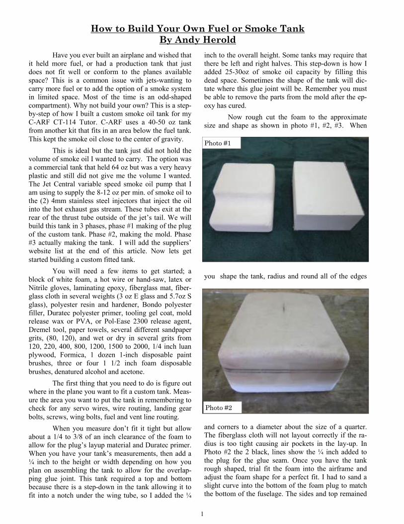
Now rough cut the foam to the approximate
size and shape as shown in photo #1, #2, #3. When
you shape the tank, radius and round all of the edges
and corners to a diameter about the size of a quarter.
The fiberglass cloth will not layout correctly if the ra-
dius is too tight causing air pockets in the lay-up. In
Photo #2 the 2 black, lines show the ¼ inch added to
the plug for the glue seam. Once you have the tank
rough shaped, trial fit the foam into the airframe and
adjust the foam shape for a perfect fit. I had to sand a
slight curve into the bottom of the foam plug to match
the bottom of the fuselage. The sides and top remained
Photo #1
Photo #2
How to Build Your Own Fuel or Smoke Tank
By Andy Herold

2
square. When you are happy with the fit, take 5.7 oz
glass cloth and cut it to the rough shape, allowing the
edges to overlap, and covering the entire foam plug.
When the epoxy has cured lightly, sand any
burs or stray fibers around the corners, blow off the
dust, then wipe the surfaces down with denatured alco-
hol and apply a layer of 3oz cloth in the same manner
as before. (See photo #3.) When I was test fitting this
tank after applying the epoxy and cloth to the foam, it
did not fit because of the ¼ inch allowance for the glue
joint. Now spread a thin layer of Bondo body putty and
fill in the weave of the cloth and indentations, while;
also blending the overlap of the cloth. You also want
to blend the corners and the overlapping areas around
the corners. Now with a tee bar sand this layer off be-
ing carful not to sand through the fiberglass cloth. (See
photo #4 & #5.) Mark any low spots and apply a sec-
ond very thin layer of Bondo body putty to fill and final
level any low spots. this does not need to be perfect.
(see photos #4 & #5). Now that we have the fiberglass
weave filled and all the low spots filled and high spots
sanded off, we can spray on the Duratec Polyester
primer. This primer will give us a tough hard finish that
we can wet-sand and polish to complete the plug. Du-
ratec wet sands very easily and is nice to work with but
Polyester resin STINKS so work in a well ventilated
Photo #5
Photo #4
Photo #3
Photo #7
Photo #8

3
area. To spray the primer I use a sprayer called a
“dump gun” with interchangeable tips for different vis-
cosity materials. This type of gun has no stop on the
material flow. When you tip it down it dumps the mate-
rial by gravity and siphon effect into the airstream. I
use about 60-80 PSI for these thick materials but differ-
ent tips; smaller for the Duratec than the gel coat. We
will use this same spray gun with the orange tooling gel
coat also. In photos #7 & #8 it shows the rough wet
block sanding (wet & dry sandpaper 600-800 grit
wrapped around a rubber hand block sander was used
to sand them flat . Photos #9 & #10 were wet sanded
with 2000 grit paper by hand. They will now be waxed
and buffed to a mirror finish. (See photos #9, #10, # 13
& #14.) Now we need to put at least 6 to 8 coats of
mold release wax on the plug and buff it to a mirror
shine to get it ready to make the mold. This is the final
step of the first phase of the three phases to making a
custom fuel or smoke oil tank.
In the first
phase we
made the
plug for a
custom tank.
Now we will
make the
mold. The
first thing
we will do is
to make a
p a r t i n g
board to
hold the
plug while
making the
actual mold.
This board
wi l l be
where we
create the top and bottom to your mold and will be
where the glue joint in your tank will be. You will need
two 1/4 inch pieces of luan plywood about 6 inches
larger than the plug’s dimensions. One will create a flat
edge all the way around the plug. The other will just act
as a flat base to work on making them one unit. You
will need a piece of Formica ( countertop material )
some Home Depots have 2 ft X 4 ft pre-cut pieces. The
Formica is not glass smooth and may have a sandy tex-
ture to it. Using 3M spray adhesive or contact cement,
laminate it to one of the pieces of luan plywood. Next
you will cut an opening in the luan/Formica for the
plug. You want this to be a very close fit, 1/8 inch max.
When laying out the cut-line use masking tape to mark
the lines on. This will prevent the Formica from chip-
ping. Using a hand jig saw and a sharp fine-toothed
blade, cut on the marked lines. Go slowly to prevent
Photo #9
Photo #11
Photo #12
Photo #10

4
chipping. You may need to sand the rounded corners
for a perfect fit. You will need to support the plug
firmly in the parting board so that it does not shift dur-
ing the lay-up process. You can use white foam or
blocks of wood like I have. (See photo #12.) Once you
have the parting board and the plug fitted to each other,
you will need to seal any gaps between the plug and
parting board. To do this, modeling clay is pushed into
the small gap with a popsicle stick. Sand one end of the
stick square and a taper to cut the clay after pushing it
into the gap all the way around the plug (See photos
#13 & #14.) If the tank is symmetrical and you need to
be able to tell front from back, use a few small blobs of
clay on the flat mold surface to create humps in the
surface. Now that we have the plug fitted to the parting
board and all the gaps filled, carefully apply 6 coats of
mold release wax to the plug and parting board being
careful not to move the plug while applying or remov-
ing the wax. Make sure to get wax on all surfaces in-
cluding the clay. While applying the wax and while it
is drying, I cut the fiberglass mat in preparation for the
lay-up process. We will need 4 layers of fiberglass mat
for each side. Cut the fiberglass mat making 4 pieces.
Two for the flat area of the parting board one for the
plug the sides the parting board, and one for the bottom
of the plug. Cut each of the pieces about 1 1/2 inches
oversized for overlap and waste. We will be fraying the
edges of the mat so that they will lay-up into the 90
degree corners better. The pieces that will be used on
the parting board will only be frayed on one side. The
pieces that will be making the ends, sides and bottom
or top will be frayed on all sides. Now that the fiber-
glass mat is cut, using pliers or your fingers pull the
edges of the mat creating the frayed edge. (See photos
#15 & #16.) Once all the wax has been applied and
buffed off, we can apply a coat Pol-Ease 2300 or 2 -3
very thin coats of PVA with a spray gun ( I like the Pol
-Ease 2300.) Coat the whole area that was waxed fol-
lowing the instructions on the can of release agent. We
are now ready to apply the orange polyester tooling gel
-coat with the dump gun. Mix the gel coat with the
hardener using the correct amount for the ambient tem-
Photo #13
Photo #14
Photo #15
Photo #16

5
perature you will be working in. (Hot temp use less
hardener- cool temp more, follow the mfg. recommen-
dations.) This is a messy process and should be done
outside due to overspray. Spray the entire plug and
parting board surface making sure that you get all cor-
ners of the plug to parting board well coated. You want
to put it on heavy but not to the point of running. It
does not have to be pretty just well covered. If you get
it too heavy the air pressure will blow the gel-coat
around and cause it to ripple. Try to avoid this but don’t
panic if it does. (See photo # 17.)
After the gel-coat has cured for about 4-6
hours, it should be hard but still tacky to the touch. We
will be applying the first two of four layers total. We
are doing this in two steps to avoid building up heat
and pulling the gel-coat away from the plug. Now
measure out a cup of polyester resin, (I started with 3oz
for this mold ) then a separate cup of hardener of the
proper amount for the resin and set it aside. Mix a
small amount of the gel-coat (about 2 oz) with hardener
then add phlox into it to make a peanut butter consis-
tency. Now spread this mixture into the corners on the
parting board with a tongue depressor, creating a filet
in the corners. Make sure there are NO AIR POCK-
ETS. (See photo #18.) Once that is done, mix your first
cup of polyester resin. Using a 1 inch disposable paint-
brush lay the first piece of mat around the parting
board, allowing the frayed edge to overlap up into the
filet you just created. Don’t worry if the mat overhangs
the parting board. Wet this glass completely out all the
way around. Now do the sides of the plug in the same
way allowing the sides to wrap down over the glass mat
that you just wet out and to wrap up over to the bottom
of the plug. Wet this glass mat out. Then add the bot-
tom to finish covering all the gel-coated surface. Once
you have that done, immediately add the second layer.
You can reverse the order of lay-up working down to
the parting board. The second layer will soak up some
of the polyester resin from the first layer. These layers
should be completely wetted but not soaking wet, (See
Photos #19 & #20.) Let these layers cure overnight.
Scuff sand the first layers and then apply layers three
Photo #17
Photo #19
Photo #20
Photo #18

6
and four in the same manner as the first two. Then let
them cure overnight. Carefully pull and separate the
mold half that you just created from the parting board.
(Watch out for the sharp shards of fiberglass mat. They
will draw blood.) The plug should come out of the part-
ing board and stay with the new mold half (See photo
#21.) Trim the edges of the fiberglass mat. Use the
edge created by the parting board as a guide and re-
move the excess glass mat, leaving a smooth edge.
Now we need to create the glue joint recess to the plug
that is required in the tank top for the tank seam, using
1/4 inch fine line vinyl tape. Wrap the tank 4 times
around as close to the new mold’s edge as possible.
(See Photo #22 the purple tape.) This will allow the
bottom to slide up into the top for assembly of the tank
later. Now apply 6 layers of wax to the whole top or
bottom as before. Apply the PVA or Pol-Ease 2300 to
the entire surfaces as before. Cut the glass mat to nec-
essary sizes for what was the parting board surface,
plug sides and top. These can be one piece, even for an
odd shaped mold like we are working with. They will
just overlap a little more. Fray the edges as before.
Follow the same steps as before, puttying the corner of
the mold over the tape and creating a filet over the tape.
Lay out the first layer of mat right on the new mold half
(just like we did on the first half) to the parting board.
Lay the second layer just like before and let it cure
overnight. Scuff the glass mat surface and apply the
third and forth layers as before and let them cure over-
night. Trim the top of the mold to match the bottom and
clean up the edges with sand paper. Now we get to
separate the 2 mold halves. Gently work a screwdriver
into the seam just a little and twist. Do this in several
locations (just a little not all at once)., working your
way around the mold. This should give you a way to
grab the mold and gently work one half off the other.
Work them apart carefully by hand. If necessary use a
soft piece of wood. Once you have the mold halves
separated, carefully work the plug out of the mold. This
can be a challenge if the plug was not waxed enough,
or the PVA or Pol-Ease 2300 was not applied evenly. I
have had to damage the plug (jam a screwdriver into it)
Photo #21
Photo #22
Photo #23
Photo #24

7
so I could get a grip on it to get it out of the mold. On
this project it pulled right out by hand. (See Photo #23
for all the parts separated.) Photo #24 shows the seam
that the vinyl tape made into the top half of this mold
for the assembly of the tank halves. Now start applying
the next 6 layers of mold wax to all the orange mold’s
smooth surfaces in preparation for laying up a tank
h a l f .
In the last phase we made a mold off of the
plug of the custom tank that we built in the first seg-
ment. In this final segment we will make and assemble
the custom tank. After you have applied the six layers
of wax, spray the mold with Pol-Ease 2300. You will
need to cut the two fiberglass cloths we will be using. I
have found that it is easier to measure and make a card
stock pattern to cut by. When measuring, make sure to
add about an inch to all sides for ease of trimming later.
(See Photo #25 & #26.) We will be using two layers of
3 oz E glass because it has a fine, tight weave and can
be worked into the corners easily. Also the epoxy fills
this tight weave helping to seal the tank. We will also
use one layer of 5.7oz S glass because is stronger than
normal fiberglass. You may have to experiment with
more layers of 5.7 oz S glass if your tank is larger. I
have had to use two layers of 3 oz E glass followed by
two or three layers of 5.7 oz S glass then another layer
of 3 oz E glass. I always start and finish with 3 oz E
glass. When cutting fiberglass it is best to cut the cloth
at a 45 degree angle to its edge to keep it from unravel-
ing. We will be sandwiching the 5.7 oz S glass between
the layers of 3oz E glass during the lay-up to help seal
the tank inside and out. I have cut enough fiberglass in
this photo for 3 tanks and have laid them out in se-
quence before starting the fiberglass lay-up.(See Photo
#27.) I have cut the fiberglass so that it fits the bottom
and sides, cutting away the corners. Save the corners
for later. You may want to cut a few extra corners from
the scraps. It is hard to cut with sticky gloved hands. I
have saved the corners and will be using those small
pieces during the lay-up. This just makes the corners
easier to work the fiberglass into and not have to worry
about air pockets. Now we are ready to start the lay-up
so we will need a few tools. I use a 1 inch disposable
paint brush to apply the epoxy and then use a 1 1/2 inch
disposable foam brush to pull the excess epoxy out af-
ter the final layer of 3 oz E glass. You may want to in-
vest in a 1/2 inch fiberglass cloth roller to help work
out bubbles. I mixed up 3 oz of epoxy for the top of this
tank and 2 1/2 oz for the bottom. I use a commercial
bulk epoxy system to dispense epoxy but you will want
to pre-measure the resin and add the hardener when
you are ready to start each half. Pour about 1 oz of ep-
oxy into the mold and spread it around with the 1 inch
brush, wetting the surfaces to help wet the glass and
hold it to the sides while wetting and working out air
pockets with your brush. I fold the first layer of E glass
Photo #25
Photo #26
Photo #27

8
sides onto itself to place it into the mold. Open it
quickly before it starts soaking up too much resin.
Work out any air pockets from the center to the edges.
Then I add the small square back into each corner that
we cut out before and saved. This will add extra
strength in the corners. (See Photo #28 & #29.) Wet
this all out and work out any air pockets. Next lay in
the 5.7 oz S glass the same way. Do not add any epoxy
at first. Use your brush and dab the glass, working it
into the first layer and absorbing any extra resin from
the first layer. Only dip your brush to add epoxy when
the resin is necessary to finish wetting out the 5.7 oz
cloth. Now add the corners back in (like the first time)
after you have wet out and removed most of the air
pockets in the main glass first. The roller is a big help
here if you have flat surfaces. Don’t forget the sides.
Now add the final layer of 3 oz glass the same way the
first two were done. When you have all three layers and
the corners in and have rolled out all the air pockets go
back and use your 1 1/2 inch foam brush to dab any
excess resin out of the fiberglass. Use a folded paper
towel to remove resin from the foam brush. Do this
until the fiberglass is wetted out but is dry enough that
you can see the weave in the final layer. Now do the
same thing for the other half. **Note which ever side
has the indentation for the tank glue joint. It will be
difficult, if not impossible, to remove all the air from
the seam area. Just do the best you can working the air
out. Resin will fill most of the voids but not all of them.
When it is all dabbed out It should look like the photos.
(See photos #30 & #31.) Now set them aside for the
epoxy to set up a little. You want the epoxy to get to a
sticky but firm condition so that we can trim the extra
fiberglass from the tank halves before the epoxy sets up
completely. When the epoxy has cured to a point where
you can touch it and is sticky (but will not get your fin-
ger wet) it is ready to trim. Start with a new single edge
razor blade and from inside the mold work the razor
blade into the fiberglass layers flush with the mold (see
Photo #28
Photo #29
Photo #30
Photo #31

9
Photo #32), pushing the razor carefully into the glass at
a 45 degree angle. Be careful that you do not pull the
fiberglass away from the mold. Pull the razor blade 360
degrees around the mold as shown in the photo. You
may have to push with a sawing motion around the cor-
ners a little due to the doubling effect of the squares we
added in the lay-up. If the glass pulls away from the
mold edges a little don’t worry just push it back into
the mold with your finger. Once trimmed let them cure
overnight. Using a tongue depressor or popsicle stick,
push in the center of one side to separate the fiberglass
tank away from the mold. Once you get it started push
the Popsicle stick down into the mold carefully and
sweep back and forth. Do this on all the sides and as far
into the corners as possible but do not push too hard.
when all the sides are free, the bottom may have
popped loose in a few spots also. Hold the tank and pull
and tug all the sides, working the tank lay-up free of the
mold. Once the halves are out of the mold, here is what
they should look like. (See Photo #33 & #34.) Let the
tanks cure for another 24 hours. Sand all the edges
lightly and then wash all the release agent off with
warm soapy water. The halves will not fit together
without sanding the edges inside the tank. The corners
will need the most work due to the small the small cor-
ner square during lay-up. Scuff up the and taper the
outside edge of the tank without the indent so it will
slide up into the other half with the indent. You will
also need to sand the inside gluing lip area and the cor-
ners of the half with the indent during the fitting of the
halves. Take your time and carefully sand until they
slide together the full 1/4 inch. They should be a sung
fit. (See Photo #35.) Wipe everything off with dena-
tured alcohol to remove the dust and any leftover re-
lease agent. Once you have the two halves fitting using
1/4 tape to put small pieces in each corner of the bot-
tom half flush with the top of the fiberglass. Then wrap
another piece all the way around using the small pieces
as your guide. (See Photo #36.) Re-wipe the joint with
the denatured alcohol. We will be gluing the halves
together with Loctite/Hysol-9462 epoxy glue using
this tape as a depth gauge. Before we glue the tank to-
Photo #32
Photo #33
Photo #34
Photo #35

10
gether we will need to make a hole in the tank to allow
the pressure to be equal and not push the glue out of the
joint. Figure out which type of fitting you want to use
(a Bob Violet Models or a Model Aviation Products
fitting) and where in the tank the fill and vent fitting
will be. BVM tank fitting & vent must be installed be-
fore the tank halves are joined. If you are using a MAP
fitting, decide where it will be and using the fitting
draw the inside of the fitting on the tank. Drill a hole in
the center of that mark for a 6/32 tap if using the MAP
fitting. (We will use a 6/32 Dubro muffler tap to pres-
sure test the tank later.) Now apply a bead around the
bottom half, right on the edge and a bead inside right
on the edge of the top halves. (See Photos #36 & #37.)
Then carefully slide the two together until they are
even with the 1/4 inch tape. Wipe the glue joint with
your finger pushing the glue down into the joint all the
way around. If there are any voids add a little glue to
fill the joint so no air pockets are left. If there is too
much glue wipe it off with your finger. Do not wipe
with the because you will remove to much glue. Now
take a paper towel and wipe the glue joint down like
you did with your finger to clean up the excess again.
Remove the tape carefully and wipe down the joint all
the way around again with your finger and light pres-
sure just to clean the little edge that will be left by the
tape. When the glue has cured this is what the glue joint
will look like inside the tank. (See Photo #38.) After
the joint has cured overnight scuff up the outside of the
tank about an 1 1/2 inch wide all around the joint for
the reinforcing tape, Use a coarse sand paper to scuff
the epoxy only; you do not want to cut into the fiber-
glass cloth. Once you have it scuffed, wipe the joint
down with denatured alcohol. Cut a length of 1 inch
fiberglass tape to wrap around the joint allowing it to
overlap about 1 inch. Mix up 1 oz of epoxy and mix it
with Cab-O-Sil to a peanut butter consistency to create
a filet around the joint top and bottom. This filet is
there so there will not be any air bubbles under the re-
inforcing tape. It will not take much epoxy to do this.
When this is done, mix up another 1oz of epoxy resin
and stick one end of the fiberglass tape centered on the
joint right on top of the epoxy filet you just made and
Photo #36
Photo #37
Photo #38
Photo #39

11
wet the tape with epoxy and an acid brush, dabbing,
wetting and leveling the filet, tape, and epoxy all in
one motion. Work on one side at a time until you have
completely wrapped the tank. Wipe the area clean with
dry paper towels to remove excess epoxy and any of
the putty that may not have been covered with the fi-
berglass tape. Let this cure overnight. You can sand the
joint tape after it cures to smooth it out and get rid of
any sharp edges or shards. Tap the hole that you drilled
for the 6/32 tap and thread in a 6/32 muffler pressure
fitting by hand that has a small length of tube attached.
Using an air compressor and a bucket of water hold the
tank underwater and pressurize the tank VERY VERY
SLOWLY AND ONLY TO ABOUT 2-3 psi MAX or
until the tank is stiff not, rock hard but stiff when you
squeeze it. Look for any bubbles indicating an air leaks
in the fiberglass and in the joint there should be no
leaks. For this tank we will be using a Model Aviation
Product fuel tank fitting for the rubber stopper which is
installed after the halves have been joined. The alumi-
num fitting will need to be scuffed up so the epoxy can
stick better. The fitting has small holes drilled through
it for the glue to protrude through and lock it in place.
Open up the hole that you marked out before for the
tapped hole to fit the MAP fittings for a snug fit. Scuff
up the glass around this hole and wipe both the fiber-
glass and aluminum fitting with denatured alcohol. Ap-
ply a bead of Loctite/Hysol 9462 to the fittings glue
surface, pushing the glue into the small opening and
also a thin bead on the fiberglass right on the edge. (See
Photos # 39, #40, #41, #42.) Press the fitting into the
tank with light pressure. You want the glue to squeeze
out around the fitting but not all of it. Wipe the glue
with your finger around the fitting to create a filet.
With a Q-Tip lightly but completely wipe the glue off
the fitting where the glue has squeezed out of the small
holes. Do not wipe the glue out of the hole. Let this
cure overnight. Build the fuel and vent fitting using the
proper type of plug and tubing for the four plane. You
can use Velcro or epoxy mounting brackets to the tank
to anchor it in place. If gluing brackets to the tank just
be sure to scuff the glass before gluing to it. I would
Photo #41
Photo #40
Photo #42
Photo #43

12
recommend using Loctite/Hysol 9462 for these brack-
ets
Now you have a fuel or smoke tank that is cus-
tom fitted. It is a lot of work to build a custom tank but
other pilots will notice the craftsmanship when the
hatch is off. I hope you enjoyed this step by step article
on how to build a custom fuel or smoke tank.
Complete and installed smoke tank in the
CARF Models CT-114 Tutor.
Suppliers web site list
http://www.aircraftspruce.com Fiberglass and hand
tools
http://www.uscomposites.com/index Epoxy and fiber-
glass
http://www.modelaviationproducts.com Fuel tank fit-
tings
http://www.bvmjets.com Fuel tank fittings
http://www.dreamworksrc.com Fuel tank neck and fit-
tings
http://www.mcmaster.com Loctite/Hysol glue gun &
tips
http://www.ellsworth.com Adhesives source

13


![[Clarinet_Institute] Herold Serenade Cl_ Viola_ Cello](https://img.pdfslide.us/doc/110x75/563db882550346aa9a9456d4/clarinetinstitute-herold-serenade-cl-viola-cello.jpg)