Embed Size (px)
Citation preview
TAKEDO- 3VFHYDROVERT
NXP
USER MANUAL
05 10-08-2017 R. BocconiREV. DATE Check and Approval R.T.
TAKEDO - 3VF HYDROVERT NXP USER MANUAL Version 05 dated 10-08-2017 2
INDEX
1 - INTRODUCTION Page 3 2 - RECOMMENDATIONS AND PRECAUTIONS Page 4 3 - INSTALLATION Page 4 4 - CONNECTION OF THE POWER CIRCUIT Page 5 5 - HYDROVERT NXP APPLICATION LAYOUT
5.1 – OIL TEMPERATURE MEASUREMENT PROBE Page Page
7 8
6 - KEYBOARD AND PROGRAMMING Page 9 7 - M1 - MONITOR MENU Page 11 8 - M2 - PARAMETERS MENU Page 12 9 - FAULTS MENU (F3 – H4) Page 16
10 - S5 AND E6 MENU Page 17 11 - ADJUSTMENT PROCEDURE
11.1 – BASIC Adjustments 11.2 – UPWARD RUN Adjustments 11.3 – UPWARD START Adjustments 11.4 – UPWARD STOP Adjustments 11.5 – UPWARD RE-LEVELLING Adjustments 11.6 – MAXIMUM INPUT POWER Adjustments 11.7 – DOWNWARD RUN Adjustments (with special power unit only) 11.8 – DOWNWARD START Adjustments 11.9 – DOWNWARD STOP Adjustments 11.10 – DOWNWARD RE-LEVELLING Adjustments
Page Page Page Page Page Page Page Page Page Page Page
17 17 18 18 19 20 20 21 21 21 22
12 - CONTROLS AND MAINTENANCE Page 23 VACON DECLARATION OF CONFORMITY Page 24
TAKEDO - 3VF HYDROVERT NXP USER MANUAL Version 05 dated 10-08-2017 3
1 – INTRODUCTION HYDROVERT NXP is an inverter with built-in EMC filter in compliance with 2004/108/EC (Electromagnetic Compatibility) and 2006/95/EC (Low Voltage) Directives, fitted with special software for hydraulic systems, which can operate with both old and new control units. It controls the UPWARD run phase and, with suitable hydraulic control unit, also the DOWNWARD run. The following advantages are attained:
• No peak currents. The maximum start-up current is the nominal current. • Possibility of setting a network maximum input power limit, to contain the contractual power. • Reduction of consumptions. • Optimisation of run comfort. • Power factor correction of the network input power. Cosϕ 0.98. • Possibility of selecting the inspection speed value.
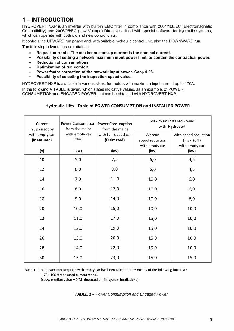
HYDROVERT NXP is available in various sizes, for motors with maximum input current up to 170A. In the following A TABLE is given, which states indicative values, as an example, of POWER CONSUMPTION and ENGAGED POWER that can be obtained with HYDROVERT NXP.
TABLE 1 – Power Consumption and Engaged Power
TAKEDO - 3VF HYDROVERT NXP USER MANUAL Version 05 dated 10-08-2017 4
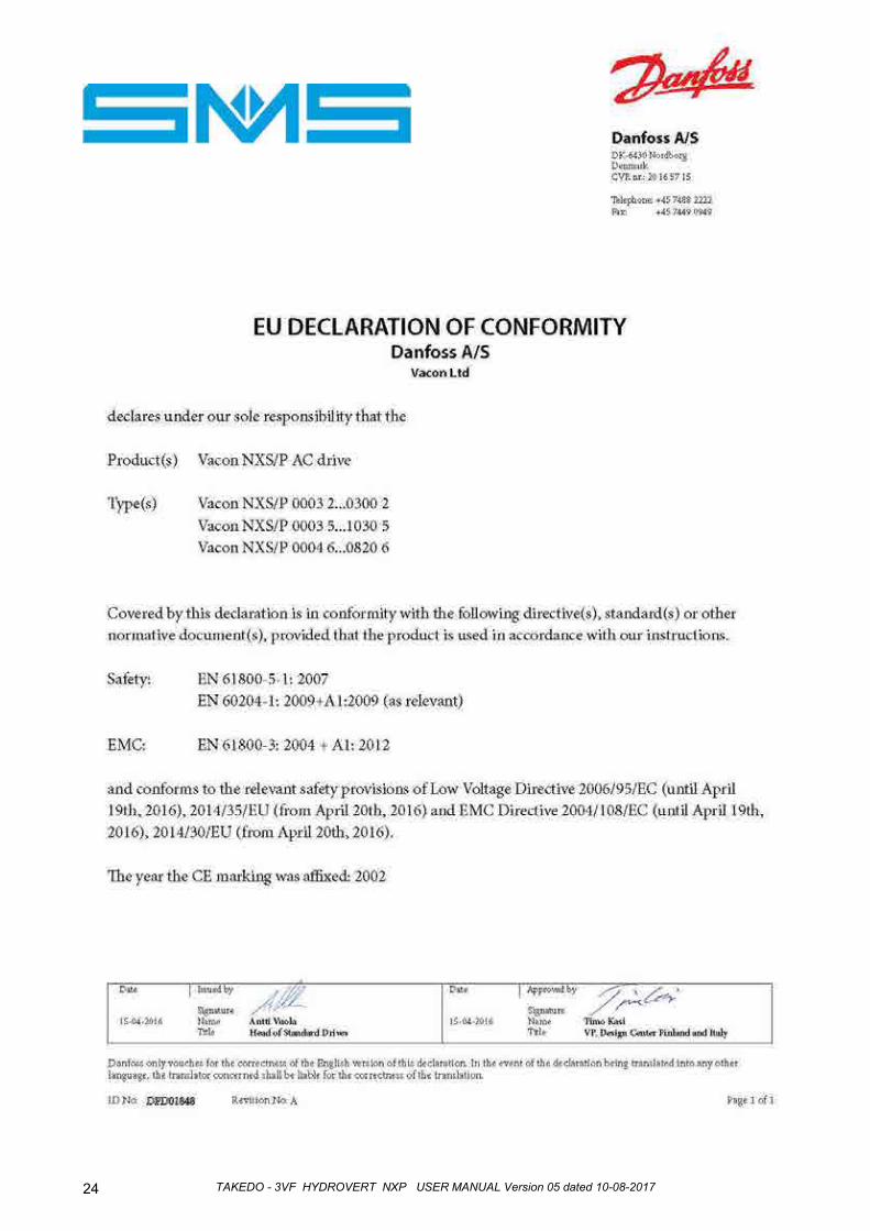
2 – RECOMMENDATIONS AND PRECAUTIONS For everything that concerns the recommendations relative to personal safety and to prevent accidental damage to the product or equipment connected to it, refer to the “SAFETY” chapter in the original VACON INSTALLATION AND MAINTENANCE TECHNICAL MANUAL (NXP series inverter) available at www.it.vacon.com, where the “Declaration of Conformity”, given on the last page of this document, is also present.
Read this manual completely before powering the appliance.
Regarding specific application on elevators, also carefully consider the following points: 1- The inverter leakage current to earth is over 30mA, a residual current device must therefore be
envisioned with Id no less than 300mA; type B or type A. For the earth connection, the regulations prescribe a cable with minimum section of 10 mm². If, on closing the master switch, the RCD intervenes, do not repeat the operation several times successively because the inverter could undergo permanent damage.
2- To prevent damage to the inverter in the event of prolonged standstill without power supply, before re-starting it is necessary to: - If the inverter is at a standstill for several months, power it for at least 1 hour in a way to
regenerate the bus condensers. - If the inverter is at a standstill for more than 1 year, power it for 1 hour with voltage that is 50%
lower than the nominal voltage and then for 1 hour at nominal voltage. 3- If necessary, the braking resistance must be connected between B+ and R-.
If it is connected between B+ and B–, this causes the inverter to break.
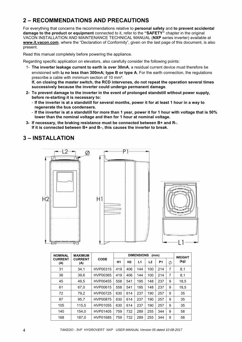
3 – INSTALLATION
NOMINAL CURRENT
(A)
MAXIMUM CURRENT
(A) CODE
DIMENSIONS (mm) WEIGHT (kg) H1 H2 L1 L2 P1
31 34,1 HVP00315 419 406 144 100 214 7 8,1 36 39,6 HVP00365 419 406 144 100 214 7 8,1 45 49,5 HVP00455 558 541 195 148 237 9 18,5 61 67,0 HVP00615 558 541 195 148 237 9 18,5 72 79,2 HVP00725 630 614 237 190 257 9 35 87 95,7 HVP00875 630 614 237 190 257 9 35
105 115,5 HVP01055 630 614 237 190 257 9 35 140 154,0 HVP01405 759 732 289 255 344 9 58 168 187,0 HVP01685 759 732 289 255 344 9 58
TAKEDO - 3VF HYDROVERT NXP USER MANUAL Version 05 dated 10-08-2017 5
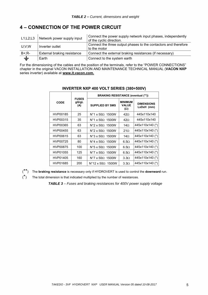
TABLE 2 – Current, dimensions and weight 4 – CONNECTION OF THE POWER CIRCUIT
L1;L2;L3 Network power supply input Connect the power supply network input phases, independently of the cyclic direction.
U;V;W Inverter outlet Connect the three output phases to the contactors and therefore to the motor
B+;R- External braking resistance Connect the external braking resistances (if necessary)
Earth Connect to the system earth
For the dimensioning of the cables and the position of the terminals, refer to the “POWER CONNECTIONS” chapter in the original VACON INSTALLATION AND MAINTENANCE TECHNICAL MANUAL (VACON NXP series inverter) available at www.it.vacon.com.
INVERTER NXP 400 VOLT SERIES (380÷500V)
CODE
FUSES gG/gL
(A)
BRAKING RESISTANCE (eventual (**))
SUPPLIED BY SMS MINIMUM VALUE
(Ω)
DIMENSIONS LxDxH (mm)
HVP00185 25 N°1 x 50Ω 1500W 42Ω 445x110x140
HVP00315 35 N°1 x 50Ω 1500W 42Ω 445x110x140
HVP00365 63 N°2 x 50Ω 1500W 14Ω 445x110x140 (*)
HVP00455 63 N°2 x 50Ω 1500W 21Ω 445x110x140 (*)
HVP00615 63 N°3 x 50Ω 1500W 14Ω 445x110x140 (*)
HVP00725 80 N°4 x 50Ω 1500W 6.5Ω 445x110x140 (*)
HVP00875 100 N°5 x 50Ω 1500W 6.5Ω 445x110x140 (*)
HVP01055 125 N°7 x 50Ω 1500W 6.5Ω 445x110x140 (*)
HVP01405 160 N°7 x 50Ω 1500W 3.3Ω 445x110x140 (*)
HVP01685 200 N°12 x 50Ω 1500W 3.3Ω 445x110x140 (*)
(**) The braking resistance is necessary only if HYDROVERT is used to control the downward run.
(*) The total dimension is that indicated multiplied by the number of resistances.
TABLE 3 – Fuses and braking resistances for 400V power supply voltage
TAKEDO - 3VF HYDROVERT NXP USER MANUAL Version 05 dated 10-08-20176
)
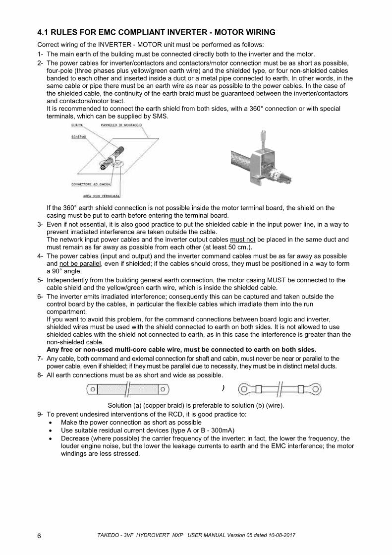
4.1 RULES FOR EMC COMPLIANT INVERTER - MOTOR WIRINGCorrect wiring of the INVERTER - MOTOR unit must be performed as follows:1- The main earth of the building must be connected directly both to the inverter and the motor.2- The power cables for inverter/contactors and contactors/motor connection must be as short as possible,
four-pole (three phases plus yellow/green earth wire) and the shielded type, or four non-shielded cables banded to each other and inserted inside a duct or a metal pipe connected to earth. In other words, in the same cable or pipe there must be an earth wire as near as possible to the power cables. In the case of the shielded cable, the continuity of the earth braid must be guaranteed between the inverter/contactors and contactors/motor tract.It is recommended to connect the earth shield from both sides, with a 360° connection or with special terminals, which can be supplied by SMS.
If the 360° earth shield connection is not possible inside the motor terminal board, the shield on the casing must be put to earth before entering the terminal board.
3- Even if not essential, it is also good practice to put the shielded cable in the input power line, in a way to prevent irradiated interference are taken outside the cable.The network input power cables and the inverter output cables must not be placed in the same duct and must remain as far away as possible from each other (at least 50 cm.).
4- The power cables (input and output) and the inverter command cables must be as far away as possible and not be parallel, even if shielded; if the cables should cross, they must be positioned in a way to form a 90° angle.
5- Independently from the building general earth connection, the motor casing MUST be connected to the cable shield and the yellow/green earth wire, which is inside the shielded cable.
6- The inverter emits irradiated interference; consequently this can be captured and taken outside the control board by the cables, in particular the flexible cables which irradiate them into the run compartment.If you want to avoid this problem, for the command connections between board logic and inverter, shielded wires must be used with the shield connected to earth on both sides. It is not allowed to use shielded cables with the shield not connected to earth, as in this case the interference is greater than the non-shielded cable.Any free or non-used multi-core cable wire, must be connected to earth on both sides.
7- Any cable, both command and external connection for shaft and cabin, must never be near or parallel to thepower cable, even if shielded; if they must be parallel due to necessity, they must be in distinct metal ducts.
8- All earth connections must be as short and wide as possible.
Solution (a) (copper braid) is preferable to solution (b) (wire).9- To prevent undesired interventions of the RCD, it is good practice to:
• Make the power connection as short as possible • Use suitable residual current devices (type A or B - 300mA)• Decrease (where possible) the carrier frequency of the inverter: in fact, the lower the frequency, the
louder engine noise, but the lower the leakage currents to earth and the EMC interference; the motor windings are less stressed.
TAKEDO - 3VF HYDROVERT NXP USER MANUAL Version 05 dated 10-08-2017 7
HYD
RO
VER
T N
XP
U
8 L2
W
V
23
22
16
10
9
TP1
V-S
PEE
D (H
IGH
/LO
W)
S-U
PW
AR
D
L1
TP
SH
IELD
ED
C
AB
LE
CO
NTA
CTO
RS
THR
EE
-P
HA
SE
LIN
E 40
0V
M
3-P
H
SH
IELD
ED
C
AB
LE
EA
RTH
CA
BLE
SH
IELD
ED
CAB
LE
SH
IELD
ED
CAB
LE
- OP
ER
ATI
ON
VO
LTAG
E
+ O
PER
ATI
ON
VO
LTA
GE
RO
1
L3
6 2
4Vdc
R- R+
S
T R
SH
IELD
ED
CAB
LE TP
TP
1
DO
WN
VA
LVE
C
OM
MA
ND
RE
LAY
Imax
<400
mA
DC
; Vm
ax<=
125
Vdc
EM
ER
GE
NC
Y
E-E
NAB
LE
15
20
26
+24V
(OU
T) 1
2 25
DO
1 RO
2
INS
PEC
TIO
N
D-D
OW
NW
AR
D
SH
IELD
ED
CAB
LE
FRE
QU
EN
CY
MO
NIT
OR
ING
RE
LAY
(for a
ny a
dvan
ced
open
ing)
Im
ax<5
0mA
DC
; V=2
4 V
dc E
XTE
RN
AL
BR
AKIN
G R
ESIS
TAN
CE
(ON
LY F
OR
OPE
RA
TIO
N IN
D
OW
NW
AR
D M
OD
E)
14
CO
NTA
CTO
RS
AN
D U
P/H
IGH
SP
EED
VA
LVE
CO
MM
AN
D
Imax
< 40
0mA
DC
; Vm
ax<=
125
Vdc
(s
ee IM
PO
RTA
NT!
not
e in
the
box)
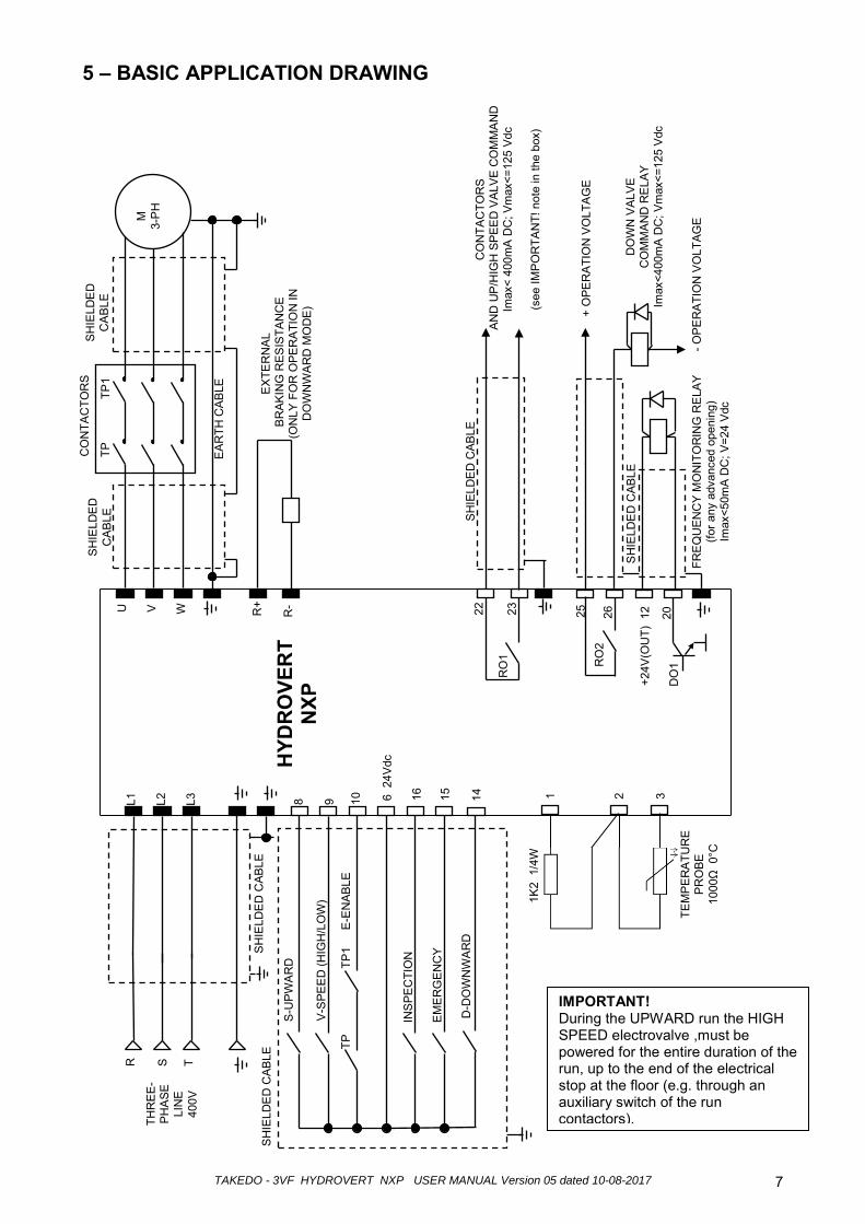
5 – BASIC APPLICATION DRAWING
1 2 3
1K2
1/4
W
TEM
PE
RA
TUR
E P
RO
BE
1000
Ω 0
°C
IMPORTANT! During the UPWARD run the HIGH SPEED electrovalve ,must be powered for the entire duration of the run, up to the end of the electrical stop at the floor (e.g. through an auxiliary switch of the run contactors).
TAKEDO - 3VF HYDROVERT NXP USER MANUAL Version 05 dated 10-08-2017 8
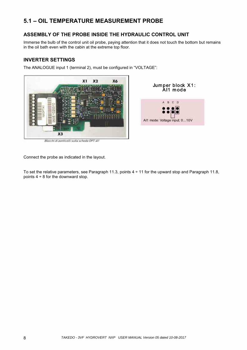
5.1 – OIL TEMPERATURE MEASUREMENT PROBE
ASSEMBLY OF THE PROBE INSIDE THE HYDRAULIC CONTROL UNIT Immerse the bulb of the control unit oil probe, paying attention that it does not touch the bottom but remains in the oil bath even with the cabin at the extreme top floor.
INVERTER SETTINGS The ANALOGUE input 1 (terminal 2), must be configured in “VOLTAGE”:
Connect the probe as indicated in the layout.
To set the relative parameters, see Paragraph 11.3, points 4 ÷ 11 for the upward stop and Paragraph 11.8, points 4 ÷ 8 for the downward stop.
TAKEDO - 3VF HYDROVERT NXP USER MANUAL Version 05 dated 10-08-2017 9
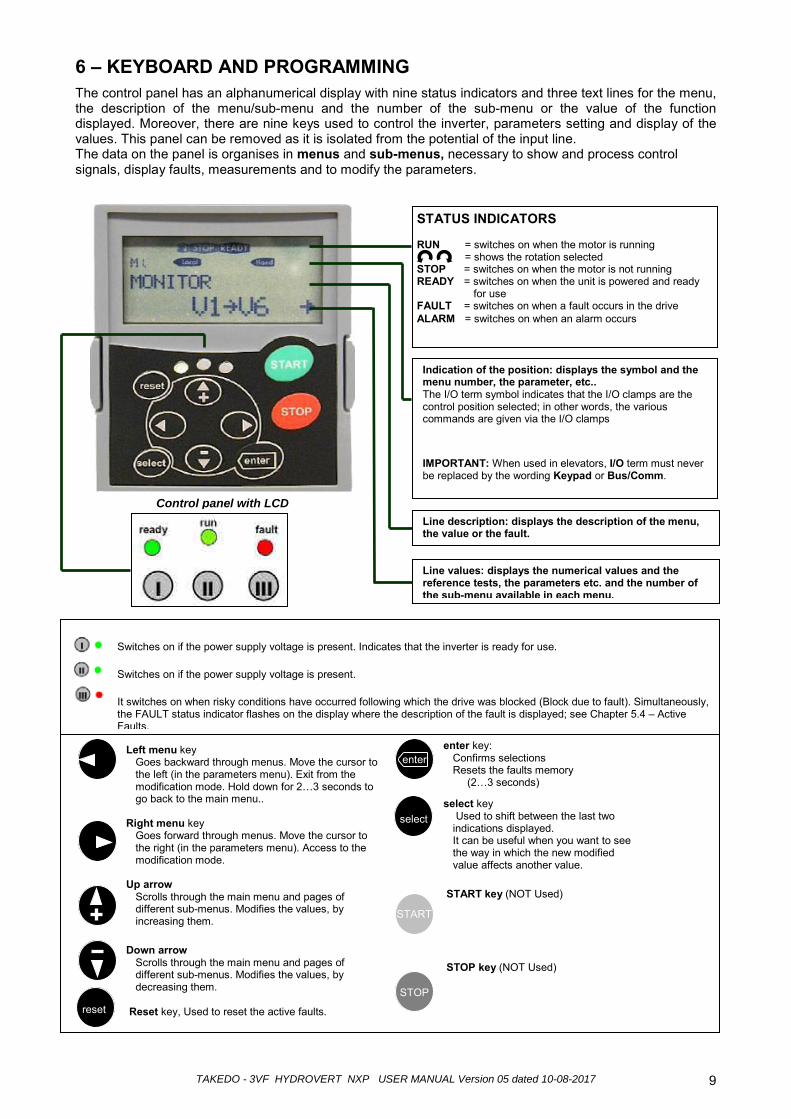
STATUS INDICATORS RUN = switches on when the motor is running
= shows the rotation selected STOP = switches on when the motor is not running READY = switches on when the unit is powered and ready
for use FAULT = switches on when a fault occurs in the drive ALARM = switches on when an alarm occurs
6 – KEYBOARD AND PROGRAMMING The control panel has an alphanumerical display with nine status indicators and three text lines for the menu, the description of the menu/sub-menu and the number of the sub-menu or the value of the function displayed. Moreover, there are nine keys used to control the inverter, parameters setting and display of the values. This panel can be removed as it is isolated from the potential of the input line. The data on the panel is organises in menus and sub-menus, necessary to show and process control signals, display faults, measurements and to modify the parameters.
Indication of the position: displays the symbol and the menu number, the parameter, etc.. The I/O term symbol indicates that the I/O clamps are the control position selected; in other words, the various commands are given via the I/O clamps IMPORTANT: When used in elevators, I/O term must never be replaced by the wording Keypad or Bus/Comm.
Control panel with LCD
Line values: displays the numerical values and the reference tests, the parameters etc. and the number of the sub-menu available in each menu.
Line description: displays the description of the menu, the value or the fault.
Switches on if the power supply voltage is present. Indicates that the inverter is ready for use. Switches on if the power supply voltage is present. It switches on when risky conditions have occurred following which the drive was blocked (Block due to fault). Simultaneously, the FAULT status indicator flashes on the display where the description of the fault is displayed; see Chapter 5.4 – Active Faults.
Left menu key Goes backward through menus. Move the cursor to the left (in the parameters menu). Exit from the modification mode. Hold down for 2…3 seconds to go back to the main menu..
Right menu key
Goes forward through menus. Move the cursor to the right (in the parameters menu). Access to the modification mode.
Up arrow
Scrolls through the main menu and pages of different sub-menus. Modifies the values, by increasing them.
Down arrow
Scrolls through the main menu and pages of different sub-menus. Modifies the values, by decreasing them.
Reset key, Used to reset the active faults.
enter key: Confirms selections Resets the faults memory
(2…3 seconds) select key
Used to shift between the last two indications displayed. It can be useful when you want to see the way in which the new modified value affects another value.
START key (NOT Used)
STOP key (NOT Used)
reset
enter
select
START
STOP
TAKEDO - 3VF HYDROVERT NXP USER MANUAL Version 05 dated 10-08-2017 10
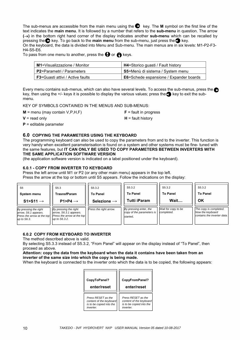
The sub-menus are accessible from the main menu using the key. The M symbol on the first line of the text indicates the main menu. It is followed by a number that refers to the sub-menu in question. The arrow (→) in the bottom right hand corner of the display indicates another sub-menu which can be recalled by pressing the key. To go back to the main menu from the sub-menu, just press the key. On the keyboard, the data is divided into Menu and Sub-menu. The main menus are in six levels: M1-P2-F3-H4-S5-E6. To pass from one menu to another, press the or keys.
M1=Visualizzazione / Monitor H4=Storico guasti / Fault history P2=Parametri / Parameters S5=Menù di sistema / System menu F3=Guasti attivi / Active faults E6=Schede espansione / Expander boards
Every menu contains sub-menus, which can also have several levels. To access the sub-menus, press the key, then using the +/- keys it is possible to display the various values; press the key to exit the sub-menu.
KEY OF SYMBOLS CONTAINED IN THE MENUS AND SUB-MENUS: M = menu (may contain V,P,H,F) F = fault in progress V = read only H = fault history P = editable parameter
6.0 COPYING THE PARAMETERS USING THE KEYBOARD The programming keyboard can also be used to copy the parameters from and to the inverter. This function is very handy when excellent parameterisation is found on a system and other systems must be fine- tuned with the same features, but IT CAN ONLY BE USED TO COPY PARAMETERS BETWEEN INVERTERS WITH THE SAME APPLICATION SOFTWARE VERSION (the application software version is indicated on a label positioned under the keyboard). 6.0.1 - COPY FROM INVERTER TO KEYBOARD Press the left arrow until M1 or P2 (or any other main menu) appears in the top left. Press the arrow at the top or bottom until S5 appears. Follow the indications on the display:
6.0.2 COPY FROM KEYBOARD TO INVERTER The method described above is valid. By selecting S5.3.3 instead of S5.3.2, “From Panel” will appear on the display instead of “To Panel”, then proceed as above. Attention: copy the data from the keyboard when the data it contains have been taken from an inverter of the same size into which the copy is being made. When the keyboard is connected to the inverter onto which the data is to be copied, the following appears:
S5
System menu
S1>S11 →
By pressing the right arrow, S6.1 appears. Press the arrow at the top up to S6.3.
S5.3
TrasnsfParam
P1>P4 →
By pressing the right arrow, S6.3.1 appears. Press the arrow at the top up to S6.3.2.
S5.3.2
To Panel
Selezione →
Press the right arrow.
S5.3.2
To Panel
Tutti iParam
By pressing enter, the copy of the parameters is started.
S5.3.2
To Panel
Wait....
Wait for copy to be completed.
S5.3.2
To Panel
OK
The copy is completed. Now the keyboard contains the inverter data.
CopyToPanel?
enter/reset Press RESET as the content of the keyboard is to be copied into the inverter.
CopyFromPanel?
enter/reset Press RESET as the content of the keyboard is to be copied into the inverter.
TAKEDO - 3VF HYDROVERT NXP USER MANUAL Version 05 dated 10-08-2017 11
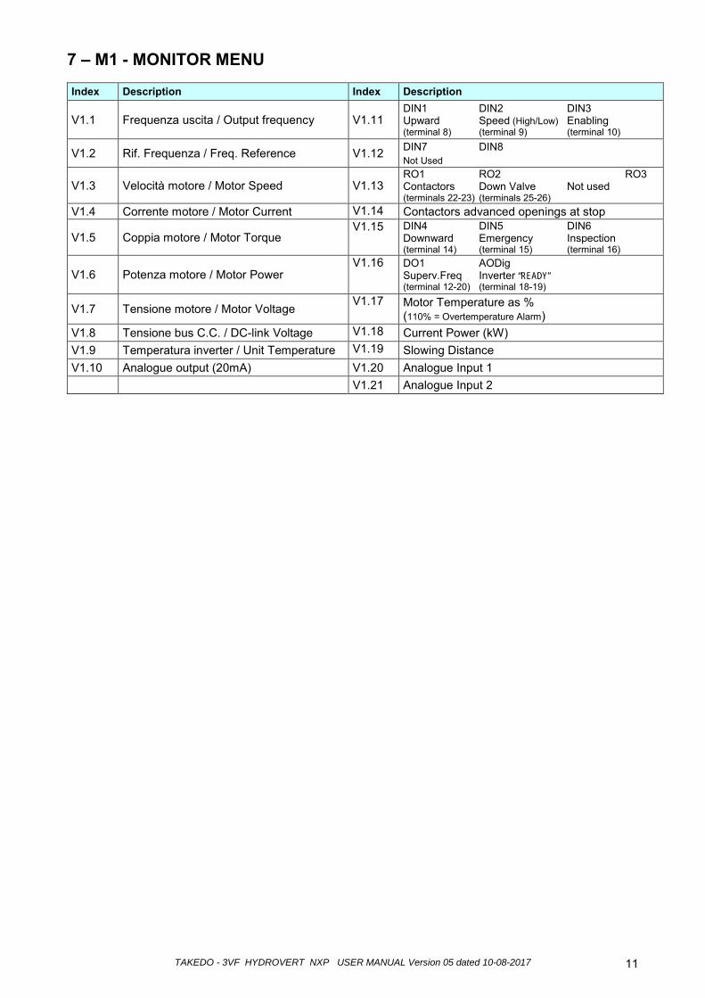
7 – M1 - MONITOR MENU Index Description Index Description
V1.1 Frequenza uscita / Output frequency V1.11 DIN1 DIN2 DIN3 Upward Speed (High/Low) Enabling (terminal 8) (terminal 9) (terminal 10)
V1.2 Rif. Frequenza / Freq. Reference V1.12 DIN7 DIN8 Not Used
V1.3 Velocità motore / Motor Speed V1.13 RO1 RO2 RO3 Contactors Down Valve Not used (terminals 22-23) (terminals 25-26)
V1.4 Corrente motore / Motor Current V1.14 Contactors advanced openings at stop
V1.5 Coppia motore / Motor Torque V1.15 DIN4 DIN5 DIN6
Downward Emergency Inspection (terminal 14) (terminal 15) (terminal 16)
V1.6 Potenza motore / Motor Power V1.16 DO1 AODig
Superv.Freq Inverter “READY” (terminal 12-20) (terminal 18-19)
V1.7 Tensione motore / Motor Voltage V1.17 Motor Temperature as %
(110% = Overtemperature Alarm) V1.8 Tensione bus C.C. / DC-link Voltage V1.18 Current Power (kW) V1.9 Temperatura inverter / Unit Temperature V1.19 Slowing Distance V1.10 Analogue output (20mA) V1.20 Analogue Input 1 V1.21 Analogue Input 2
TAKEDO - 3VF HYDROVERT NXP USER MANUAL Version 05 dated 10-08-2017 12
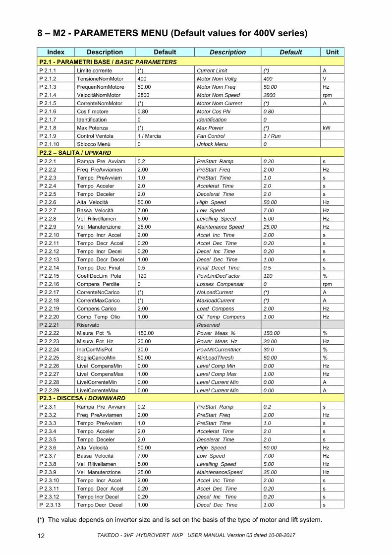
8 – M2 - PARAMETERS MENU (Default values for 400V series)
Index Description Default Description Default Unit P2.1 - PARAMETRI BASE / BASIC PARAMETERS P 2.1.1 Limite corrente (*) Current Limit (*) A P 2.1.2 TensioneNomMotor 400 Motor Nom Voltg 400 V P 2.1.3 FrequenNomMotore 50.00 Motor Nom Freq 50.00 Hz P 2.1.4 VelocitàNomMotor 2800 Motor Nom Speed 2800 rpm P 2.1.5 CorrenteNomMotor (*) Motor Nom Current (*) A P 2.1.6 Cos fi motore 0.80 Motor Cos Phi 0.80 P 2.1.7 Identification 0 Identification 0 P 2.1.8 Max Potenza (*) Max Power (*) kW P 2.1.9 Control Ventola 1 / Marcia Fan Control 1 / Run P 2.1.10 Sblocco Menù 0 Unlock Menu 0 P2.2 – SALITA / UPWARD P 2.2.1 Rampa Pre Avviam 0.2 PreStart Ramp 0.20 s P 2.2.2 Freq PreAvviamen 2.00 PreStart Freq 2.00 Hz P 2.2.3 Tempo PreAvviam 1.0 PreStart Time 1.0 s P 2.2.4 Tempo Acceler 2.0 Accelerat Time 2.0 s P 2.2.5 Tempo Deceler 2.0 Decelerat Time 2.0 s P 2.2.6 Alta Velocità 50.00 High Speed 50.00 Hz P 2.2.7 Bassa Velocità 7.00 Low Speed 7.00 Hz P 2.2.8 Vel Rilivellamen 5.00 Levelling Speed 5.00 Hz P 2.2.9 Vel Manutenzione 25.00 Maintenance Speed 25.00 Hz P 2.2.10 Tempo Incr Accel 2.00 Accel Inc Time 2.00 s P 2.2.11 Tempo Decr Accel 0.20 Accel Dec Time 0.20 s P 2.2.12 Tempo Incr Decel 0.20 Decel Inc Time 0.20 s P 2.2.13 Tempo Decr Decel 1.00 Decel Dec Time 1.00 s P 2.2.14 Tempo Dec Final 0.5 Final Decel Time 0.5 s P 2.2.15 CoeffDecLim Pote 120 PowLimDecFactor 120 % P 2.2.16 Compens Perdite 0 Losses Compensat 0 rpm P 2.2.17 CorrenteNoCarico (*) NoLoadCurrent (*) A P 2.2.18 CorrentMaxCarico (*) MaxloadCurrent (*) A P 2.2.19 Compens Carico 2.00 Load Compens 2.00 Hz P 2.2.20 Comp Temp Olio 1.00 Oil Temp Compens 1.00 Hz P 2.2.21 Riservato Reserved P 2.2.22 Misura Pot % 150.00 Power Meas % 150.00 % P 2.2.23 Misura Pot Hz 20.00 Power Meas Hz 20.00 Hz P 2.2.24 IncrCorrMisPot 30.0 PowMcCurrentIncr 30.0 % P 2.2.25 SogliaCaricoMin 50.00 MinLoadThresh 50.00 % P 2.2.26 Livel CompensMin 0.00 Level Comp Min 0.00 Hz P 2.2.27 Livel CompensMax 1.00 Level Comp Max 1.00 Hz P 2.2.28 LivelCorrenteMin 0.00 Level Current Min 0.00 A P 2.2.29 LivelCorrenteMax 0.00 Level Current Min 0.00 A P2.3 - DISCESA / DOWNWARD P 2.3.1 Rampa Pre Avviam 0.2 PreStart Ramp 0.2 s P 2.3.2 Freq PreAvviamen 2.00 PreStart Freq 2.00 Hz P 2.3.3 Tempo PreAvviam 1.0 PreStart Time 1.0 s P 2.3.4 Tempo Acceler 2.0 Accelerat Time 2.0 s P 2.3.5 Tempo Deceler 2.0 Decelerat Time 2.0 s P 2.3.6 Alta Velocità 50.00 High Speed 50.00 Hz P 2.3.7 Bassa Velocità 7.00 Low Speed 7.00 Hz P 2.3.8 Vel Rilivellamen 5.00 Levelling Speed 5.00 Hz P 2.3.9 Vel Manutenzione 25.00 MaintenanceSpeed 25.00 Hz P 2.3.10 Tempo Incr Accel 2.00 Accel Inc Time 2.00 s P 2.3.11 Tempo Decr Accel 0.20 Accel Dec Time 0.20 s P 2.3.12 Tempo Incr Decel 0.20 Decel Inc Time 0.20 s P 2.3.13 Tempo Decr Decel 1.00 Decel Dec Time 1.00 s
(*) The value depends on inverter size and is set on the basis of the type of motor and lift system.
TAKEDO - 3VF HYDROVERT NXP USER MANUAL Version 05 dated 10-08-2017 13
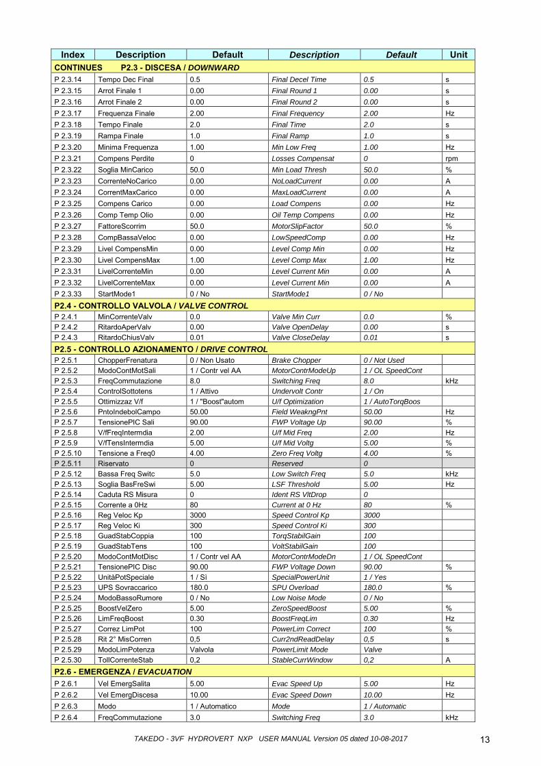
Index Description Default Description Default Unit
CONTINUES P2.3 - DISCESA / DOWNWARD P 2.3.14 Tempo Dec Final 0.5 Final Decel Time 0.5 s P 2.3.15 Arrot Finale 1 0.00 Final Round 1 0.00 s P 2.3.16 Arrot Finale 2 0.00 Final Round 2 0.00 s P 2.3.17 Frequenza Finale 2.00 Final Frequency 2.00 Hz P 2.3.18 Tempo Finale 2.0 Final Time 2.0 s P 2.3.19 Rampa Finale 1.0 Final Ramp 1.0 s P 2.3.20 Minima Frequenza 1.00 Min Low Freq 1.00 Hz P 2.3.21 Compens Perdite 0 Losses Compensat 0 rpm P 2.3.22 Soglia MinCarico 50.0 Min Load Thresh 50.0 % P 2.3.23 CorrenteNoCarico 0.00 NoLoadCurrent 0.00 A P 2.3.24 CorrentMaxCarico 0.00 MaxLoadCurrent 0.00 A P 2.3.25 Compens Carico 0.00 Load Compens 0.00 Hz P 2.3.26 Comp Temp Olio 0.00 Oil Temp Compens 0.00 Hz P 2.3.27 FattoreScorrim 50.0 MotorSlipFactor 50.0 % P 2.3.28 CompBassaVeloc 0.00 LowSpeedComp 0.00 Hz P 2.3.29 Livel CompensMin 0.00 Level Comp Min 0.00 Hz P 2.3.30 Livel CompensMax 1.00 Level Comp Max 1.00 Hz P 2.3.31 LivelCorrenteMin 0.00 Level Current Min 0.00 A P 2.3.32 LivelCorrenteMax 0.00 Level Current Min 0.00 A P 2.3.33 StartMode1 0 / No StartMode1 0 / No P2.4 - CONTROLLO VALVOLA / VALVE CONTROL P 2.4.1 MinCorrenteValv 0.0 Valve Min Curr 0.0 % P 2.4.2 RitardoAperValv 0.00 Valve OpenDelay 0.00 s P 2.4.3 RitardoChiusValv 0.01 Valve CloseDelay 0.01 s P2.5 - CONTROLLO AZIONAMENTO / DRIVE CONTROL P 2.5.1 ChopperFrenatura 0 / Non Usato Brake Chopper 0 / Not Used P 2.5.2 ModoContMotSali 1 / Contr vel AA MotorContrModeUp 1 / OL SpeedCont P 2.5.3 FreqCommutazione 8.0 Switching Freq 8.0 kHz P 2.5.4 ControlSottotens 1 / Attivo Undervolt Contr 1 / On P 2.5.5 Ottimizzaz V/f 1 / "Boost"autom U/f Optimization 1 / AutoTorqBoos P 2.5.6 PntoIndebolCampo 50.00 Field WeakngPnt 50.00 Hz P 2.5.7 TensionePIC Sali 90.00 FWP Voltage Up 90.00 % P 2.5.8 V/fFreqIntermdia 2.00 U/f Mid Freq 2.00 Hz P 2.5.9 V/fTensIntermdia 5.00 U/f Mid Voltg 5.00 % P 2.5.10 Tensione a Freq0 4.00 Zero Freq Voltg 4.00 % P 2.5.11 Riservato 0 Reserved 0 P 2.5.12 Bassa Freq Switc 5.0 Low Switch Freq 5.0 kHz P 2.5.13 Soglia BasFreSwi 5.00 LSF Threshold 5.00 Hz P 2.5.14 Caduta RS Misura 0 Ident RS VltDrop 0 P 2.5.15 Corrente a 0Hz 80 Current at 0 Hz 80 % P 2.5.16 Reg Veloc Kp 3000 Speed Control Kp 3000 P 2.5.17 Reg Veloc Ki 300 Speed Control Ki 300 P 2.5.18 GuadStabCoppia 100 TorqStabilGain 100 P 2.5.19 GuadStabTens 100 VoltStabilGain 100 P 2.5.20 ModoContMotDisc 1 / Contr vel AA MotorContrModeDn 1 / OL SpeedCont P 2.5.21 TensionePIC Disc 90.00 FWP Voltage Down 90.00 % P 2.5.22 UnitàPotSpeciale 1 / Sì SpecialPowerUnit 1 / Yes P 2.5.23 UPS Sovraccarico 180.0 SPU Overload 180.0 % P 2.5.24 ModoBassoRumore 0 / No Low Noise Mode 0 / No P 2.5.25 BoostVelZero 5.00 ZeroSpeedBoost 5.00 % P 2.5.26 LimFreqBoost 0.30 BoostFreqLim 0.30 Hz P 2.5.27 Correz LimPot 100 PowerLim Correct 100 % P 2.5.28 Rit 2° MisCorren 0,5 Curr2ndReadDelay 0,5 s P 2.5.29 ModoLimPotenza Valvola PowerLimit Mode Valve P 2.5.30 TollCorrenteStab 0,2 StableCurrWindow 0,2 A P2.6 - EMERGENZA / EVACUATION P 2.6.1 Vel EmergSalita 5.00 Evac Speed Up 5.00 Hz P 2.6.2 Vel EmergDiscesa 10.00 Evac Speed Down 10.00 Hz P 2.6.3 Modo 1 / Automatico Mode 1 / Automatic P 2.6.4 FreqCommutazione 3.0 Switching Freq 3.0 kHz
TAKEDO - 3VF HYDROVERT NXP USER MANUAL Version 05 dated 10-08-2017 14
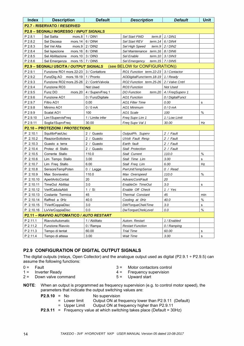
Index Description Default Description Default Unit P2.7 - RISERVATO / RESERVED P2.8 – SEGNALI INGRESSO / INPUT SIGNALS P 2.8.1 Sel Salita mors.8 1 / DIN1 Sel Start FWD term.8 1 / DIN1 P 2.8.2 Sel Discesa mors.14 6 / DIN4 Sel Start REV term.14 6 / DIN4 P 2.8.3 Sel Vel Alta mors.9 2 / DIN2 Sel High Speed term.9 2 / DIN2 P 2.8.4 Sel Ispezione mors.16 8 / DIN6 Sel Maintenance term.16 8 / DIN6 P 2.8.5 Sel Abilitazione mors.10 3 / DIN3 Sel Enable term.10 3 / DIN3 P 2.8.6 Sel Emergenza mors.15 7 / DIN5 Sel Emergency term.15 7 / DIN5 P2.9 – SEGNALI USCITA / OUTPUT SIGNALS (see BELOW for CONFIGURATION)) P 2.9.1 Funzione RO1 mors.22-23 3 / Contattore RO1 Function term.22-23 3 / Contactor P 2.9.2 FunzDig AO mors.18-19 1 / Pronto AODigitalFunct term.18-19 1 / Ready P 2.9.3 Funzione RO2 mors.25-26 2 / ContrValvola RO2 Function term.25-26 2 / Valve Cntrl P 2.9.4 Funzione RO3 Not Used RO3 Function Not Used P 2.9.5 Funz DO mors.20 4 / SupervFreq 1 DO Function term.20 4 / FreqSuperv 1 P 2.9.6 Funzione AO1 0 / FunzDigitale AO1 Function 0 / DigitalFunct P 2.9.7 Filtro AO1 0.00 AO1 Filter Time 0.00 s P 2.9.8 Minimo AO1 0 / 0 mA AO1 Minimum 0 / 0 mA P 2.9.9 Scalat AO1 100 AO1 Scale 100 % P 2.9.10 Lim1SupervisFreq 1 / Limite infer Freq Supv Lim 1 1 / Low Limit P 2.9.11 Soglia1SuprvFreq 30.00 Freq Supv Val 1 30.00 Hz
P2.10 – PROTEZIONI / PROTECTIONS P 2.10.1 SquilibrFasiUsc 2 / Guasto OutputPh. Superv 2 / Fault P 2.10.2 ReazionSottotens 2 / Guasto UVolt Fault Resp 2 / Fault P 2.10.3 Guasto a terra 2 / Guasto Earth fault 2 / Fault P 2.10.4 Protez di Stallo 2 / Guasto Stall Protection 2 / Fault P 2.10.5 Corrente Stallo 110.0 Stall Current 110.0 % P 2.10.6 Lim Tempo Stallo 3.00 Stall Time Lim 3.00 s P 2.10.7 Lim Freq Stallo 6.00 Stall Freq Lim 6.00 Hz P 2.10.8 SensoreTempPoten 0 / Legge PwrUnitTempSense 0 / Read P 2.10.9 Max Sovraveloc 110.0 Max Overspeed 110.0 % P 2.10.10 ApertAnticContat 20 AdvancContFault 20 P 2.10.11 TimeOut Abilitaz 3.0 EnableOn TimeOut 3.0 s P 2.10.12 VerifCadutaAbili 1 / Sì Enable Off Check 1 / Yes P 2.10.13 Costante Termica 45 Thermal Constant 45 min P 2.10.14 Raffred a 0Hz 40.0 Cooling at 0Hz 40.0 % P 2.10.15 TVerifCoppiaDisc 3.0 DWTorqueChekTime 3.0 s P 2.10.16 LivVerCoppiaDisc 0.0 DwTorqueChekLevel 0.0 % P2.11 – RIAVVIO AUTOMATICO / AUTO RESTART P 2.11.1 RiavvioAutomatic 1 / Abilitato Autom. Restart 1 / Enabled P 2.11.2 Funzione Riavvio 0 / Rampa Restart Function 0 / Ramping P 2.11.3 Tempo di tentat 60.00 Trial Time 60.00 s P 2.11.4 Tempo di attesa 3.00 Wait Time 3.00 s
P2.9 CONFIGURATION OF DIGITAL OUTPUT SIGNALS The digital outputs (relays, Open Collector) and the analogue output used as digital (P2.9.1 ÷ P2.9.5) can assume the following functions: 0 = Fault 3 = Motor contactors control 1 = Inverter Ready 4 = Frequency supervision 2 = Down valve command 5 = Upward start
NOTE: When an output is programmed as frequency supervision (e.g. to control motor speed), the parameters that indicate the output switching values are: P2.9.10 = No No supervision = Lower limit Output ON at frequency lower than P2.9.11 (Default) = Upper Limit Output ON at frequency higher than P2.9.11 P2.9.11 = Frequency value at which switching takes place (Default = 30Hz)
TAKEDO - 3VF HYDROVERT NXP USER MANUAL Version 05 dated 10-08-2017 15
Index Description Default Description Default Unit
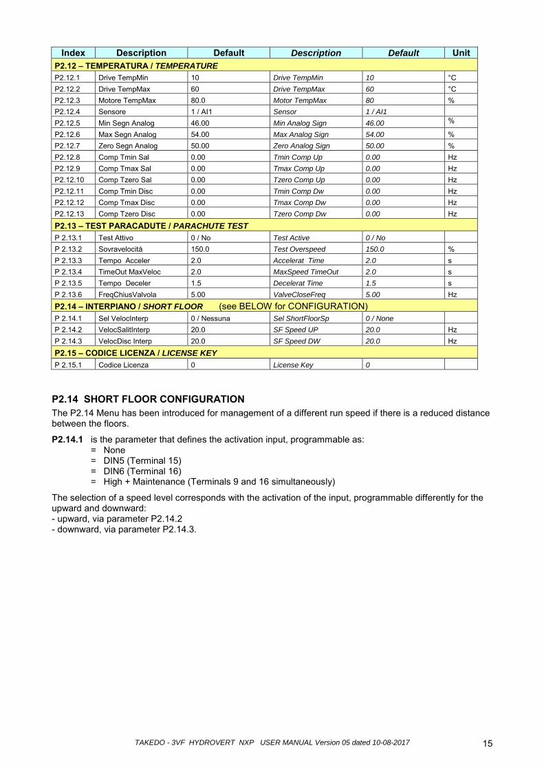
P2.12 – TEMPERATURA / TEMPERATURE P2.12.1 Drive TempMin 10 Drive TempMin 10 °C P2.12.2 Drive TempMax 60 Drive TempMax 60 °C P2.12.3 Motore TempMax 80.0 Motor TempMax 80 % P2.12.4 Sensore 1 / AI1 Sensor 1 / AI1 P2.12.5 Min Segn Analog 46.00 Min Analog Sign 46.00 % P2.12.6 Max Segn Analog 54.00 Max Analog Sign 54.00 % P2.12.7 Zero Segn Analog 50.00 Zero Analog Sign 50.00 % P2.12.8 Comp Tmin Sal 0.00 Tmin Comp Up 0.00 Hz P2.12.9 Comp Tmax Sal 0.00 Tmax Comp Up 0.00 Hz P2.12.10 Comp Tzero Sal 0.00 Tzero Comp Up 0.00 Hz P2.12.11 Comp Tmin Disc 0.00 Tmin Comp Dw 0.00 Hz P2.12.12 Comp Tmax Disc 0.00 Tmax Comp Dw 0.00 Hz P2.12.13 Comp Tzero Disc 0.00 Tzero Comp Dw 0.00 Hz
P2.13 – TEST PARACADUTE / PARACHUTE TEST P 2.13.1 Test Attivo 0 / No Test Active 0 / No P 2.13.2 Sovravelocità 150.0 Test Overspeed 150.0 % P 2.13.3 Tempo Acceler 2.0 Accelerat Time 2.0 s P 2.13.4 TimeOut MaxVeloc 2.0 MaxSpeed TimeOut 2.0 s P 2.13.5 Tempo Deceler 1.5 Decelerat Time 1.5 s P 2.13.6 FreqChiusValvola 5.00 ValveCloseFreq 5.00 Hz P2.14 – INTERPIANO / SHORT FLOOR (see BELOW for CONFIGURATION) P 2.14.1 Sel VelocInterp 0 / Nessuna Sel ShortFloorSp 0 / None P 2.14.2 VelocSalitInterp 20.0 SF Speed UP 20.0 Hz P 2.14.3 VelocDisc Interp 20.0 SF Speed DW 20.0 Hz P2.15 – CODICE LICENZA / LICENSE KEY P 2.15.1 Codice Licenza 0 License Key 0
P2.14 SHORT FLOOR CONFIGURATION The P2.14 Menu has been introduced for management of a different run speed if there is a reduced distance between the floors.
P2.14.1 is the parameter that defines the activation input, programmable as: = None = DIN5 (Terminal 15) = DIN6 (Terminal 16) = High + Maintenance (Terminals 9 and 16 simultaneously)
The selection of a speed level corresponds with the activation of the input, programmable differently for the upward and downward: - upward, via parameter P2.14.2 - downward, via parameter P2.14.3.
TAKEDO - 3VF HYDROVERT NXP USER MANUAL Version 05 dated 10-08-2017 16
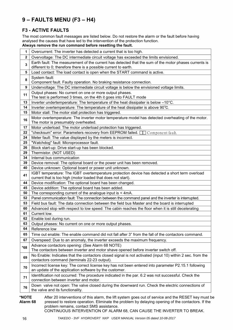
9 – FAULTS MENU (F3 – H4)
F3 - ACTIVE FAULTS The most common fault messages are listed below. Do not restore the alarm or the fault before having analysed the causes that have led to the intervention of the protection function. Always remove the run command before resetting the fault.
1 Overcurrent: The inverter has detected a current that is too high. 2 Overvoltage: The DC intermediate circuit voltage has exceeded the limits envisioned.
3 Earth fault: The measurement of the current has detected that the sum of the motor phases currents is different to 0; therefore there is a possible current to earth.
5 Load contact: The load contact is open when the START command is active.
8 System fault: Component fault. Faulty operation. No braking resistance connection.
9 Undervoltage: The DC intermediate circuit voltage is below the envisioned voltage limits.
11 Output phases: No current on one or more output phases. The test is performed 3 times, on the 4th it goes into FAULT mode
13 Inverter undertemperature: The temperature of the heat dissipater is below –10°C. 14 Inverter overtemperature: The temperature of the heat dissipater is above 90. 15 Motor stall: The motor stall protection has triggered.
16 Motor overtemperature: The inverter motor temperature model has detected overheating of the motor. The motor is presumably overheated.
17 Motor underload: The motor underload protection has triggered. 22 "checksum" error: Parameters recovery from EEPROM failed. Compone nt fa ult. 24 Meter fault: The value displayed by the meters is incorrect. 25 "Watchdog" fault: Microprocessor fault. 26 Block start-up: Drive start-up has been blocked. 29 Thermistor. (NOT USED) 34 Internal bus communication 39 Device removal: The optional board or the power unit has been removed. 40 Device unknown: Optional board or power unit unknown.
41 IGBT temperature: The IGBT overtemperature protection device has detected a short term overload current that is too high (motor loaded that does not start).
44 Device modification: The optional board has been changed. 45 Device addition: The optional board has been added. 50 The corresponding current of the analogue input is < 4mA. 52 Panel communication fault: The connection between the command panel and the inverter is interrupted. 53 Field bus fault: The data connection between the field bus Master and the board is interrupted 60 Advanced stop with respect to low speed: The cabin reaches the floor when it is still decelerating 61 Current low. 62 Enable lost during run. 63 Output phases: No current on one or more output phases. 64 Reference low 65 Time out enable: The enable command did not fall after 3” from the fall of the contactors command. 67 Overspeed: Due to an anomaly, the inverter exceeds the maximum frequency.
*68 Advance contactors opening: (See Alarm 68 NOTE) The contactors between inverter and motor shave opened before inverter switch off.
69 No Enable: Indicates that the contactors closed signal is not activated (input 10) within 2 sec. from the contactors command (terminals 22-23 output).
70 Incorrect license key: The correct license key has not been entered into parameter P2.15.1 following an update of the application software by the customer.
71 Identification not occurred: The procedure indicated in the par. 6.2 was not successful. Check the connection between inverter and motor.
76 Down valve not open: The valve closed during the downward run. Check the electric connections of the valve and its functionality.
*NOTE After 20 interventions of this alarm, the lift system goes out of service and the RESET key must be Alarm 68 pressed to restore operation. Eliminate the problem by delaying opening of the contactors. If the
problem remains, contact SMS assistance. CONTINUOUS INTERVENTION OF ALARM 68, CAN CAUSE THE INVERTER TO BREAK.
TAKEDO - 3VF HYDROVERT NXP USER MANUAL Version 05 dated 10-08-2017 17
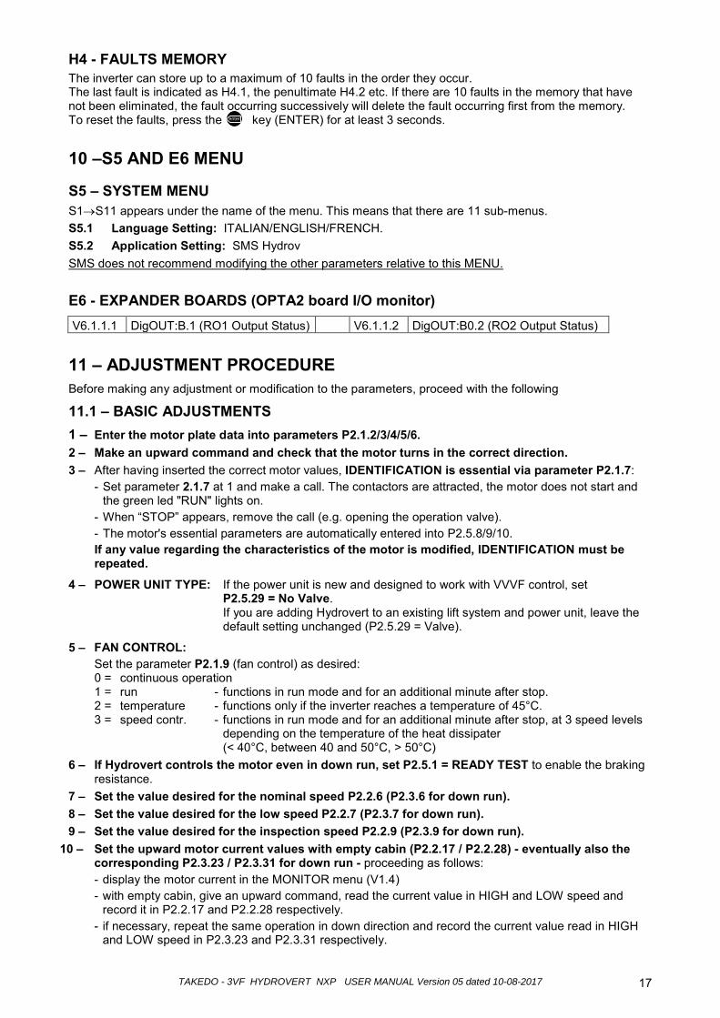
H4 - FAULTS MEMORY The inverter can store up to a maximum of 10 faults in the order they occur. The last fault is indicated as H4.1, the penultimate H4.2 etc. If there are 10 faults in the memory that have not been eliminated, the fault occurring successively will delete the fault occurring first from the memory. To reset the faults, press the ent key (ENTER) for at least 3 seconds.
10 –S5 AND E6 MENU
S5 – SYSTEM MENU S1→S11 appears under the name of the menu. This means that there are 11 sub-menus. S5.1 Language Setting: ITALIAN/ENGLISH/FRENCH. S5.2 Application Setting: SMS Hydrov SMS does not recommend modifying the other parameters relative to this MENU.
E6 - EXPANDER BOARDS (OPTA2 board I/O monitor) V6.1.1.1 DigOUT:B.1 (RO1 Output Status) V6.1.1.2 DigOUT:B0.2 (RO2 Output Status)
11 – ADJUSTMENT PROCEDURE Before making any adjustment or modification to the parameters, proceed with the following
11.1 – BASIC ADJUSTMENTS 1 – Enter the motor plate data into parameters P2.1.2/3/4/5/6. 2 – Make an upward command and check that the motor turns in the correct direction. 3 – After having inserted the correct motor values, IDENTIFICATION is essential via parameter P2.1.7:
- Set parameter 2.1.7 at 1 and make a call. The contactors are attracted, the motor does not start and the green led "RUN" lights on.
- When “STOP” appears, remove the call (e.g. opening the operation valve). - The motor's essential parameters are automatically entered into P2.5.8/9/10. If any value regarding the characteristics of the motor is modified, IDENTIFICATION must be repeated.
4 – POWER UNIT TYPE: If the power unit is new and designed to work with VVVF control, set P2.5.29 = No Valve. If you are adding Hydrovert to an existing lift system and power unit, leave the default setting unchanged (P2.5.29 = Valve).
5 – FAN CONTROL: Set the parameter P2.1.9 (fan control) as desired: 0 = continuous operation 1 = run - functions in run mode and for an additional minute after stop. 2 = temperature - functions only if the inverter reaches a temperature of 45°C. 3 = speed contr. - functions in run mode and for an additional minute after stop, at 3 speed levels
depending on the temperature of the heat dissipater (< 40°C, between 40 and 50°C, > 50°C)
6 – If Hydrovert controls the motor even in down run, set P2.5.1 = READY TEST to enable the braking resistance.
7 – Set the value desired for the nominal speed P2.2.6 (P2.3.6 for down run). 8 – Set the value desired for the low speed P2.2.7 (P2.3.7 for down run). 9 – Set the value desired for the inspection speed P2.2.9 (P2.3.9 for down run).
10 – Set the upward motor current values with empty cabin (P2.2.17 / P2.2.28) - eventually also the corresponding P2.3.23 / P2.3.31 for down run - proceeding as follows: - display the motor current in the MONITOR menu (V1.4) - with empty cabin, give an upward command, read the current value in HIGH and LOW speed and
record it in P2.2.17 and P2.2.28 respectively. - if necessary, repeat the same operation in down direction and record the current value read in HIGH
and LOW speed in P2.3.23 and P2.3.31 respectively.
enter
TAKEDO - 3VF HYDROVERT NXP USER MANUAL Version 05 dated 10-08-201718
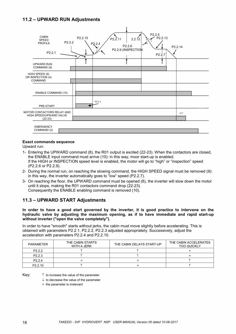
11.2 – UPWARD RUN Adjustments
Exact commands sequence Upward run:1- Entering the UPWARD command (8), the R01 output is excited (22-23). When the contactors are closed,
the ENABLE input command must arrive (10): in this way, moor start-up is enabled. If the HIGH or INSPECTION speed level is enabled, the motor will go to “high” or “inspection” speed (P2.2.6 or P2.2.9).
2- During the normal run, on reaching the slowing command, the HIGH SPEED signal must be removed (9): in this way, the inverter automatically goes to “low” speed (P2.2.7).
3- On reaching the floor, the UPWARD command must be opened (8), the inverter will slow down the motor until it stops, making the R01 contactors command drop (22-23). Consequently the ENABLE enabling command is removed (10).
11.3 – UPWARD START Adjustments
In order to have a good start governed by the inverter, it is good practice to intervene on the hydraulic valve by adjusting the maximum opening, as if to have immediate and rapid start-up without inverter ("open the valve completely").
In order to have "smooth" starts without jerks, the cabin must move slightly before accelerating. This is obtained with parameters P2.2.1, P2.2.2, P2.2.3 adjusted appropriately. Successively, adjust the acceleration with parameters P2.2.4 and P2.2.10.
PARAMETER THE CABIN STARTSWITH A JERK THE CABIN DELAYS START-UP THE CABIN ACCELERATES
TOO QUICKLYP2.2.2 ↑ ↑ =P2.2.3 ↑ ↑ =P2.2.4 = = ↑P2.2.10 ↑ = ↑
Key: ↑ to increase the value of the parameter↓ to decrease the value of the parameter= the parameter is irrelevant
UPWARD RUNCOMMAND (8)
HIGH SPEED (9)OR INSPECTION (4)
COMMAND
CABIN SPEED
PROFILE
ENABLE COMMAND (10)
2.2.12
PRE-STARTP2.2.3
P2.2.13
P2.2.4P2.2.11
P2.2.5
P2.2.2P2.2.14
EMERGENCYCOMMAND (2)
P2.2.10
P2.2.1 P2.2.7
MOTOR CONTACTORS RELAY AND HIGH SPEED/UPWARD VALVE
(22-23)
0.3’’
P2.2.6P2.2.9 (INSPECTION
TAKEDO - 3VF HYDROVERT NXP USER MANUAL Version 05 dated 10-08-2017 19
11.4 – UPWARD STOP Adjustments When the HIGH SPEED command is removed and the UPWARD command remains, the slowing phase starts; on arrival at the floor the UPWARD command is removed and the motor automatically goes to zero speed. Adjusting the stop with empty cabin, by setting the parameters P2.2.7 (Low Speed) and P2.2.14 (Final Deceleration) in a way to obtain the desired stop accuracy.
PARAMETER THE CABIN ARRIVES AT THE FLOOR TOO
SLOWLY
THE CABIN ARRIVES WITHOUT SLOW
SPEED
THE CABIN MOVES AT SLOW SPEED BUT
PASSES BEYOND THE FLOOR
AFTER HAVING MOVED AT SLOW SPEED,
THE CABIN STOPS BEFORE THE FLOOR
P2.2.5 ↑ ↓ = P2.2.7 = = ↓ ↑ P2.2.14 = = ↓ ↑
Display the motor current in HIGH speed in the MONITOR menu (V1.4) and check that the value read is set in P2.2.17.
Stop accuracy can depend on the load in the cabin (weight to be lifted) and the temperature of the oil.
To make stopping accurate in any load condition, proceed as follows: 1. Load the cabin to nominal load, read the motor current in HIGH speed in the MONITOR menu (V1.4)
and enter the value in P2.2.18. 2. Perform the arrival test at the floor with cabin at full load: normally the cabin stops slightly before the
floor. Increase parameter P2.2.19 until the desired stopping accuracy is obtained.
3. Finally, with the cabin empty, control that stopping accuracy has remained the one obtained with the initial tests.
To make stopping accurate in any oil temperature condition, proceed as follows: 4. The PT1000 temperature probe must be installed as indicated in Par. 4.1 and connected as in the
layout in Par. 4 (terminals 1 - 2 - 3). 5. Set P2.2.20 (Oil Temp Comp) = 0 and enable the inverter on reading of the temperature, setting P2.12.4
= 1/AI1. 6. If not already present as factory settings, the reference values of the probe analogue signal must be
entered into P2.12.5 and P2.12.6: P2.12.5 = 46% P2.12.6 = 54%.
7. Read the oil temperature value (in %) in the MONITOR menu in V1.20 and enter the value read in P2.12.7.
8. Make many runs in a way to heat the oil up as much as possible (the oil heats up much quickly if the cabin is loaded).
9. If stopping is not accurate with hot oil (normally the upward cabin stops before the floor, as the heat varies the viscosity of the oil and consequently lowers the levelling speed), increase P2.12.9 to obtain the same stopping level had with cold oil.
10. Unload the cabin, leave the oil to cool until it reaches its initial temperature and check that the stopping accuracy has not altered.
11. If with very cold oil (as for example at the first runs in the winter season) the cabin stops higher with respect to the level of the floor, enter the value necessary to obtain accurate stopping into P2.12.8
TAKEDO - 3VF HYDROVERT NXP USER MANUAL Version 05 dated 10-08-2017 20
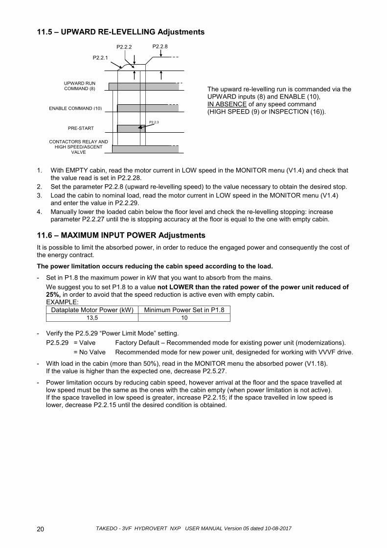
11.5 – UPWARD RE-LEVELLING Adjustments
1. With EMPTY cabin, read the motor current in LOW speed in the MONITOR menu (V1.4) and check that the value read is set in P2.2.28.
2. Set the parameter P2.2.8 (upward re-levelling speed) to the value necessary to obtain the desired stop. 3. Load the cabin to nominal load, read the motor current in LOW speed in the MONITOR menu (V1.4)
and enter the value in P2.2.29. 4. Manually lower the loaded cabin below the floor level and check the re-levelling stopping: increase
parameter P2.2.27 until the is stopping accuracy at the floor is equal to the one with empty cabin.
11.6 – MAXIMUM INPUT POWER Adjustments It is possible to limit the absorbed power, in order to reduce the engaged power and consequently the cost of the energy contract.
The power limitation occurs reducing the cabin speed according to the load.
- Set in P1.8 the maximum power in kW that you want to absorb from the mains. We suggest you to set P1.8 to a value not LOWER than the rated power of the power unit reduced of 25%, in order to avoid that the speed reduction is active even with empty cabin. EXAMPLE:
Dataplate Motor Power (kW) Minimum Power Set in P1.8 13,5 10
- Verify the P2.5.29 “Power Limit Mode” setting. P2.5.29 = Valve Factory Default – Recommended mode for existing power unit (modernizations).
= No Valve Recommended mode for new power unit, designeded for working with VVVF drive.
- With load in the cabin (more than 50%), read in the MONITOR menu the absorbed power (V1.18). If the value is higher than the expected one, decrease P2.5.27.
- Power limitation occurs by reducing cabin speed, however arrival at the floor and the space travelled at low speed must be the same as the ones with the cabin empty (when power limitation is not active). If the space travelled in low speed is greater, increase P2.2.15; if the space travelled in low speed is lower, decrease P2.2.15 until the desired condition is obtained.
P2.2.3
P2.2.8 P2.2.2
UPWARD RUN COMMAND (8)
ENABLE COMMAND (10)
PRE-START
CONTACTORS RELAY AND HIGH SPEED/ASCENT
VALVE
P2.2.1
The upward re-levelling run is commanded via the UPWARD inputs (8) and ENABLE (10), IN ABSENCE of any speed command (HIGH SPEED (9) or INSPECTION (16)).
TAKEDO - 3VF HYDROVERT NXP USER MANUAL Version 05 dated 10-08-2017 21
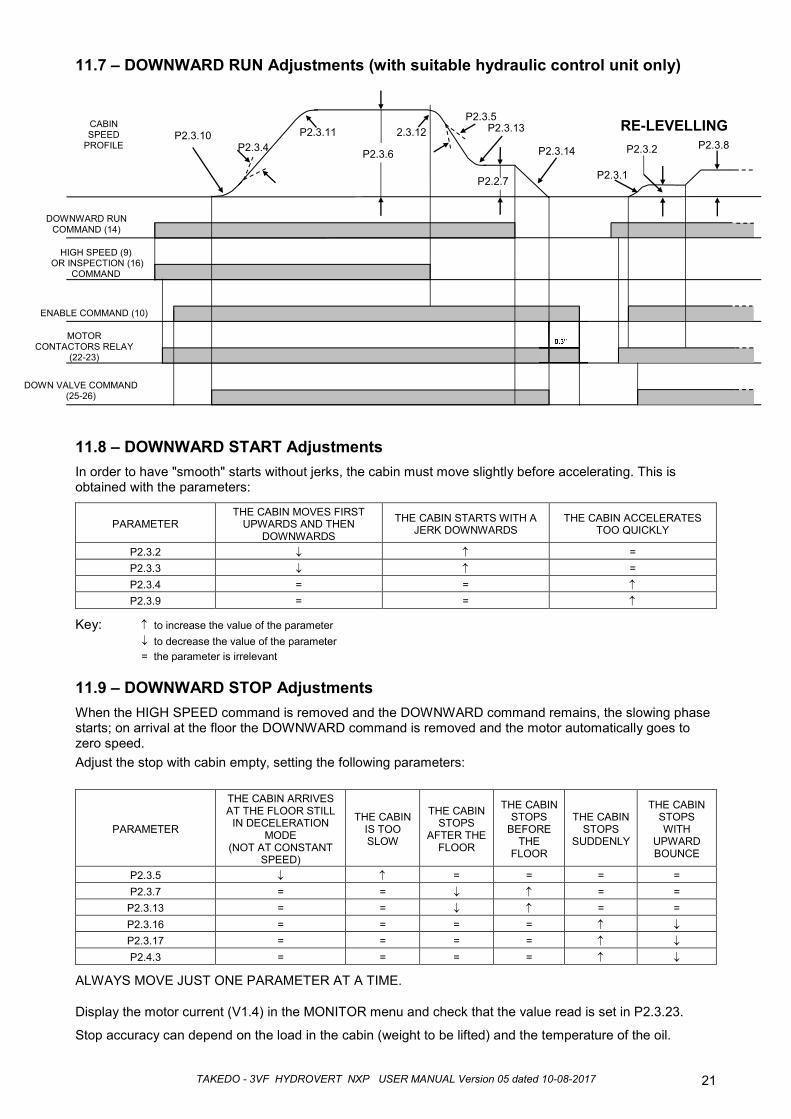
DOWNWARD RUNCOMMAND (14)
HIGH SPEED (9)OR INSPECTION (16)
COMMAND
CABIN SPEED
PROFILE2.3.12
DOWN VALVE COMMAND (25-26)
P2.3.13
P2.3.4P2.3.11
P2.3.5
P2.3.14
MOTOR CONTACTORS RELAY
(22-23)
P2.3.10
P2.2.7
ENABLE COMMAND (10)
P2.3.8P2.3.2
P2.3.1
11.7 – DOWNWARD RUN Adjustments (with suitable hydraulic control unit only)
11.8 – DOWNWARD START AdjustmentsIn order to have "smooth" starts without jerks, the cabin must move slightly before accelerating. This is obtained with the parameters:
PARAMETERTHE CABIN MOVES FIRST
UPWARDS AND THEN DOWNWARDS
THE CABIN STARTS WITH A JERK DOWNWARDS
THE CABIN ACCELERATES TOO QUICKLY
P2.3.2 ↓ ↑ =P2.3.3 ↓ ↑ =P2.3.4 = = ↑P2.3.9 = = ↑
Key: ↑ to increase the value of the parameter↓ to decrease the value of the parameter= the parameter is irrelevant
11.9 – DOWNWARD STOP AdjustmentsWhen the HIGH SPEED command is removed and the DOWNWARD command remains, the slowing phase starts; on arrival at the floor the DOWNWARD command is removed and the motor automatically goes to zero speed.Adjust the stop with cabin empty, setting the following parameters:
PARAMETER
THE CABIN ARRIVES AT THE FLOOR STILL
IN DECELERATION MODE
(NOT AT CONSTANT SPEED)
THE CABIN IS TOO SLOW
THE CABIN STOPS
AFTER THE FLOOR
THE CABIN STOPS
BEFORE THE
FLOOR
THE CABIN STOPS
SUDDENLY
THE CABIN STOPS WITH
UPWARD BOUNCE
P2.3.5 ↓ ↑ = = = =P2.3.7 = = ↓ ↑ = =
P2.3.13 = = ↓ ↑ = =P2.3.16 = = = = ↑ ↓P2.3.17 = = = = ↑ ↓P2.4.3 = = = = ↑ ↓
ALWAYS MOVE JUST ONE PARAMETER AT A TIME.
Display the motor current (V1.4) in the MONITOR menu and check that the value read is set in P2.3.23.
Stop accuracy can depend on the load in the cabin (weight to be lifted) and the temperature of the oil.
P2.3.6
0.3’’
RE-LEVELLING
TAKEDO - 3VF HYDROVERT NXP USER MANUAL Version 05 dated 10-08-2017 22
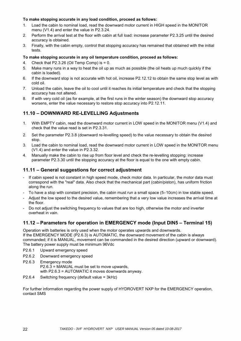
To make stopping accurate in any load condition, proceed as follows: 1. Load the cabin to nominal load, read the downward motor current in HIGH speed in the MONITOR
menu (V1.4) and enter the value in P2.3.24. 2. Perform the arrival test at the floor with cabin at full load: increase parameter P2.3.25 until the desired
accuracy is obtained. 3. Finally, with the cabin empty, control that stopping accuracy has remained that obtained with the initial
tests.
To make stopping accurate in any oil temperature condition, proceed as follows: 4. Check that P2.3.26 (Oil Temp Comp) is = 0. 5. Make many runs in a way to heat the oil up as much as possible (the oil heats up much quickly if the
cabin is loaded). 6. If the downward stop is not accurate with hot oil, increase P2.12.12 to obtain the same stop level as with
cold oil. 7. Unload the cabin, leave the oil to cool until it reaches its initial temperature and check that the stopping
accuracy has not altered. 8. If with very cold oil (as for example, at the first runs in the winter season) the downward stop accuracy
worsens, enter the value necessary to restore stop accuracy into P2.12.11.
11.10 – DOWNWARD RE-LEVELLING Adjustments
1. With EMPTY cabin, read the downward motor current in LOW speed in the MONITOR menu (V1.4) and check that the value read is set in P2.3.31.
2. Set the parameter P2.3.8 (downward re-levelling speed) to the value necessary to obtain the desired stop.
3. Load the cabin to nominal load, read the downward motor current in LOW speed in the MONITOR menu (V1.4) and enter the value in P2.3.32.
4. Manually make the cabin to rise up from floor level and check the re-levelling stopping: increase parameter P2.3.30 until the stopping accuracy at the floor is equal to the one with empty cabin.
11.11 – General suggestions for correct adjustment - If cabin speed is not constant in high speed mode, check motor data. In particular, the motor data must
correspond with the "real" data. Also check that the mechanical part (cabin/piston), has uniform friction along the run.
- To have a stop with constant precision, the cabin must run a small space (5÷10cm) in low stable speed. - Adjust the low speed to the desired value, remembering that a very low value increases the arrival time at
the floor. - Do not adjust the switching frequency to values that are too high, otherwise the motor and inverter
overheat in vain.
11.12 – Parameters for operation in EMERGENCY mode (Input DIN5 – Terminal 15) Operation with batteries is only used when the motor operates upwards and downwards. If the EMERGENCY MODE (P2.6.3) is AUTOMATIC, the downward movement of the cabin is always commanded; if it is MANUAL, movement can be commanded in the desired direction (upward or downward). The battery power supply must be minimum 96Vdc P2.6.1 Upward emergency speed P2.6.2 Downward emergency speed P2.6.3 Emergency mode
P2.6.3 = MANUAL must be set to move upwards, with P2.6.3 = AUTOMATIC it moves downwards anyway.
P2.6.4 Switching frequency (default value = 3kHz) For further information regarding the power supply of HYDROVERT NXP for the EMERGENCY operation, contact SMS
TAKEDO - 3VF HYDROVERT NXP USER MANUAL Version 05 dated 10-08-2017 23
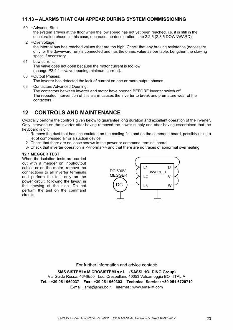
11.13 – ALARMS THAT CAN APPEAR DURING SYSTEM COMMISSIONING
60 = Advance Stop: the system arrives at the floor when the low speed has not yet been reached, i.e. it is still in the deceleration phase; in this case, decrease the deceleration time 2.2.5 (2.3.5 DOWNWARD).
2 = Overvoltage: the internal bus has reached values that are too high. Check that any braking resistance (necessary only for the downward run) is connected and has the ohmic value as per table. Lengthen the slowing space if necessary.
61 = Low current: The valve does not open because the motor current is too low (change P2.4.1 = valve opening minimum current).
63 = Output Phases: The inverter has detected the lack of current on one or more output phases.
68 = Contactors Advanced Opening: The contactors between inverter and motor have opened BEFORE inverter switch off. The repeated intervention of this alarm causes the inverter to break and premature wear of the contactors.
12 – CONTROLS AND MAINTENANCE Cyclically perform the controls given below to guarantee long duration and excellent operation of the inverter. Only intervene on the inverter after having removed the power supply and after having ascertained that the keyboard is off. 1- Remove the dust that has accumulated on the cooling fins and on the command board, possibly using a
jet of compressed air or a suction device. 2- Check that there are no loose screws in the power or command terminal board. 3- Check that inverter operation is <<normal>> and that there are no traces of abnormal overheating.
12.1 MEGGER TEST When the isolation tests are carried out with a megger on input/output cables or on the motor, remove the connections to all inverter terminals and perform the test only on the power circuit, following the layout in the drawing at the side. Do not perform the test on the command circuits.
For further information and advice contact: SMS SISTEMI e MICROSISTEMI s.r.l. (SASSI HOLDING Group)
Via Guido Rossa, 46/48/50 Loc. Crespellano 40053 Valsamoggia BO - ITALIA Tel. : +39 051 969037 Fax : +39 051 969303 Technical Service: +39 051 6720710
E-mail : [email protected] Internet : www.sms-lift.com
U V W
L1 L2 L3
INVERTER
DC
DC 500V MEGGER
TAKEDO - 3VF HYDROVERT NXP USER MANUAL Version 05 dated 10-08-201724