Embed Size (px)
Citation preview

Running Pattern Generation and Its Evaluation
Using a Realistic Humanoid Model
Takashi Nagasaki�1, Shuuji Kajita�2, Kazuhito Yokoi�2, Kenji Kaneko�2, Kazuo Tanie�1�2
�1University of Tsukuba,�2National Institute of Advanced Industrial Science and Technology(AIST)
E-mail: [email protected]
Abstract
This paper describes a possibility of running hu-
manoid robot based on the physical properties of an
existing humanoid robot HRP-2L. To generate run-
ning motion, we develop a general method to con-
trol the total linear/angular momentum of multi-link
system. By this method, we can generate a reliable
running pattern. Conducting simulations which take
into account of physical restrictions, we show that
our humanoid robot can run at least with 0.5[m/s].
1 Introduction
Research on humanoid robots is currently one of
the most exciting topics in the �eld of robotics and
there exist many ongoing projects [2][4][6][11][16].
Most of them are focusing on biped w alking as an
important subject and have already demonstrated
reliable dynamic biped walking. Watching those suc-
cessful demonstrations, one can ask a natural ques-
tion, \Can we build a running humanoid?"
We believe it is worthwhile as a technical chal-
lenge from the following reasons. First, study of run-
ning will add new functions of mobility to humanoid
robots. For example, jumping over large obstacles
or a �ssure might be realized by a derivative of the
running control. Second, studying extreme situation
will give us an insight to improve the hardware itself.
Current robots are too fragile to operate in the vari-
ous environments. Even in an experiment of walking
at low speed, we must treat them carefully. We are
expecting to overcome this fragility in the process of
developing a running humanoid.
Running robots have intensively studied by Raib-
ert and his colleague [13]. Their famous hopping
robots driven by pneumatic and hydraulic actua-
tors performed various actions including somersault
[12]. Using similar control strategy, Hodgins simu-
lated running human in the computer graphics [5].
Ahmadi and Buehler studied running monopods
from a standpoint of energy eÆciency. Their ARL
Momopod II[1] is an electrically powered running
robot of 18[kg] weight and could run at 1.25[m/s]
with a power expenditure of only 48[W].
All of those robots have spring mechanism to re-
trieve the kinetic energy in running cycles. It is ob-
vious that such spring helps running but they might
prevent the ordinal humanoid activities like walking,
carrying an object, etc. Since our intention is to add
a running function to a versatile humanoid robot, we
start with a mechanism without springs. A similar
approach is taken by Gienger et al.[2].
In our previous report, we investigated a run-
ning motion of an existing humanoid robot HRP-1
of 1.6[m] height and 117[kg] weight, which was de-
veloped in the Humanoid Robotics Project (HRP)
of the Ministry of Economy, Trade and Industry of
Japan. To generate a running pattern we proposed
a method based on a simple inverted pendulum with
some ad hoc modi�cations to absorb the modeling
error. From our simulation, it turned out that we
require unrealizable power of over 7[kW] for some
actuators of HRP-1 running at 2.9[m/s].
In this paper, we examine a lighter biped robot
HRP-2L which was also developed in HRP. For run-
ning pattern generation, we introduce a new method
using precise physical parameters of a robot. After
discussing a hopping pattern for less power consump-
tion, we show a realistic running under the consider-
ation of the actuator limits.
2 Humanoid Model
To build a running humanoid with conventional
actuators, we must make it as light as possible. How-
ever, there is a physical and technical limitation for
weight saving. Therefore we decided to set the model
parameter based on the speci�cation of an existing
humanoid robot.
Proceedings of the 2003 IEEE International Conference on Robotics & Automation Taipei, Taiwan, September 14-19, 2003
0-7803-7736-2/03/$17.00 ©2003 IEEE 1336

Figure 1: HRP-2L
2.1 HRP-2L
HRP-2L(Figure 1) is a biped robot that was de-
veloped in the Humanoid Robotics Project(HRP)
of the Ministry of Economy, Trade and Industry of
Japan[10]. Table 1 shows the speci�cation of HRP-
2L, and Table 2 shows the speci�cation of leg actu-
ators. HRP-2L has batteries and dummy weights,
and these elements can be easily removed. Remov-
ing them and considering the little increase of weight
for optional equipment for running, we assume that
weight of HRP-2L will be reduced to 30[kg]. This is
about one-fourth of the HRP-1 weight:117[kg].
HRP-2L has rubber bushs at each foot part. These
compliance elements are e�ective in reducing the
landing impact force and torque.
2.2 Actuator limits
Following two points should be taken into consid-
eration as a limit of the motor capability.
The �rst point is maximum torque and speed.
Generally, there is a relationship about a motor as
follows,
� = KT i (1)
V = KE! +Rai (2)
where � is motor torque, i is motor current, V is
motor voltage, ! is angular velocity, KT and KE
are torque constant and back electro-motive force
constant, Ra is armature resistance. The maximum
torque is determined by the maximum current imax
which can be supplied to a motor and the maximum
speed is mainly related with maximum voltage Vmax
which can be applied. imax is restricted by the ca-
pability of a motor driver, and Vmax is determined
by the power supply voltage. From the speci�cation
Table 1: Speci�cation of HRP-2L
6D.O.F/Legs(Hip:3 Knee:1 Ankle:2)
Upper leg length: 300[mm]
Size Lower leg length: 300[mm]
Ankle length: 91[mm]
Length between hip joints: 120[mm]
Legs:8.6[kg/leg]�2[legs] = 17.2[kg]
Batteries: 11.4[kg]
Weight Controller: 7.0[kg]
Dummy Weights: 22.6[kg]
Total: 58.2[kg]
Table 2: Actuator speci�cation of HRP-2L
Joint Actuator
Hip Yaw 20[W]
Roll 90[W]
Pitch 90[W]
Knee Pitch 150[W]
Ankle Pitch 90[W]
Roll 70[W]
of motor drivers of HRP-2L, imax is 20[A], Vmax is
48[V ]. To represent actuator limits in the simula-
tion, the calculated motor current is saturated by
imax. For maximum voltage, instead of simulating
the power supply in detail, we check whether the
calculated motor voltage is lower than Vmax. If the
calculated motor voltage does not exceed the limit,
it implies that the running motion is possible under
the given power supply.
The second point is the restriction about the heat
generation of a motor. If heat generation of a mo-
tor is large, a rotor can burn out. For this reason,
the temperature of a rotor must not exceed the per-
mitted value. We can calculate the temperature of a
rotor as follows,
ÆR = ÆU + PJRth(1� e
�t
�th ) (3)
Rth = Rth1 +Rth2 (4)
where t is time, ÆR is rotor temperature, ÆU
is ambient temperature,PJ is heat generation of
a motor, Rth1/Rth2 is thermal resistance rotor-
housing/housing-ambient and �th is thermal time
constant. If the temperature of a rotor reaches per-
mitted temperature too quick, a robot can not per-
form the running motion. As the guideline of the du-
ration, we specify 30[s] or more operation time under
the permitted temperature.
1337
3 Momentum equation
To derive our new method of running pattern gen-
eration, this section shows the basic relationship be-
tween robot motion and its linear/angular momen-
tum.
3.1 Momentum and joint velocities
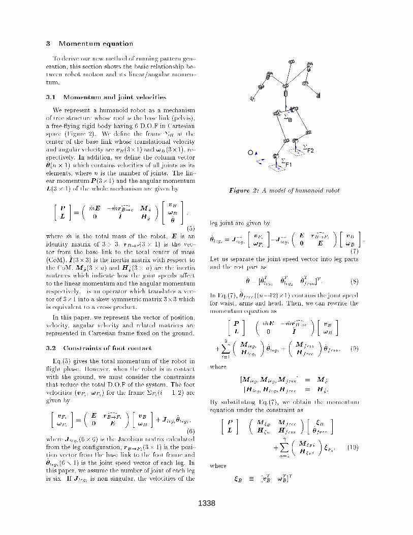
We represent a humanoid robot as a mechanism
of tree structure whose root is the base link (pelvis),
a free- ying rigid body having 6 D.O.F in Cartesian
space (Figure 2). We de�ne the frame �B at the
center of the base link whose translational velocity
and angular velocity are vB(3�1) and !B(3�1), re-
spectively. In addition, we de�ne the column vector_�(n � 1) which contains velocities of all joints as its
elements, where n is the number of joints. The lin-
ear momentumP (3�1) and the angular momentum
L(3� 1) of the whole mechanism are given by
�P
L
�=
�~mE � ~m drB!c M _�
0 ~I H _�
�24 vB
!B
_�
35 ;(5)
where ~m is the total mass of the robot, E is an
identity matrix of 3 � 3, rB!c(3 � 1) is the vec-
tor from the base link to the total center of mass
(CoM), ~I(3�3) is the inertia matrix with respect to
the CoM. M _�(3 � n) and H _�(3� n) are the inertia
matrices which indicate how the joint speeds a�ect
to the linear momentum and the angular momentum
respectively. ^is an operator which translates a vec-
tor of 3�1 into a skew symmetric matrix 3�3 which
is equivalent to a cross product.
In this paper, we represent the vector of position,
velocity, angular velocity and related matrices are
represented in Cartesian frame �xed on the ground.
3.2 Constraints of foot contact
Eq.(5) gives the total momentum of the robot in
ight phase. However, when the robot is in contact
with the ground, we must consider the constraints
that reduce the total D.O.F of the system. The foot
velocities (vFi , !Fi ) for the frame �Fi (i = 1; 2) are
given by�vFi
!Fi
�=
�E drB!Fi
0 E
��vB
!B
�+ J legi
_�legi ;
(6)
where J legi(6� 6) is the Jacobian matrix calculated
from the leg con�guration, rB!Fi (3� 1) is the posi-
tion vector from the base link to the foot frame and_�legi (6 � 1) is the joint speed vector of each leg. In
this paper, we assume the number of joint of each leg
is six. If J legi is non singular, the velocities of the
Figure 2: A model of humanoid robot
leg joint are given by
_�legi = J�1
legi
�vFi
!Fi
��J
�1
legi
�E drB!Fi
0 E
��vB
!B
�:
(7)
Let us separate the joint speed vector into leg parts
and the rest part as
_� = [ _�T
leg1_�T
leg2_�T
free]T: (8)
In Eq.(7), _�free((n�12)�1) contains the joint speed
for waist, arms and head. Then, we can rewrite the
momentum equation as�P
L
�=
�~mE � ~m drB!c
0 ~I
��vB
!B
�+
2Xi=1
�M legi
H legi
�_�legi +
�M free
Hfree
�_�free; (9)
where
[M leg1M leg2M free] = M _�
[Hleg1H leg2Hfree] = H _�:
By substituting Eq.(7), we obtain the momentum
equation under the constraint as�P
L
�=
�M �B M free
H�B Hfree
���B_�free
�+
2Xn=1
�M �F i
H�F i
��Fi
; (10)
where
�B � [vTB !TB]
T
1338

�Fi� [vTFi !
TFi]T�
M �B
H�B
��
�~mE � ~m drB!c
0 ~I
��
2Xn=1
�M �F i
H�F i
��E drB!Fi
0 E
��M �F i
H�F i
��
�M legi
H legi
�J�1
legi:
The second term in the right hand side of Eq.(10) in-
dicates the extra momentumgenerated by specifying
the foot speed.
4 Momentum Control
Following the result of the last section, we propose
the Momentum Control, which is a method to gen-
erate the whole body motion of a humanoid robot
such that the resulted total momentum becomes the
spci�ed value. By this method, we can generate not
only a running pattern but also various dynamic mo-
tions.
4.1 Setting momentum reference
For every mechanical system, no matter how its
structure or behavior is complicated, we can deter-
mine the position of the CoM ~c, the linear momen-
tum P and the angular momentum L for the total
mechanism.
Dividing the total linear momentum P by the to-
tal mass ~m, we obtain the translational speed of the
CoM.d
dt~c =
P
~m(11)
Thus, we can control the position of the CoM by
manipulating the translational momentum.
As the extension of this, we propose a method of
control or pattern generation by manipulating the
total (linear and angular) momentum. Let us call
this method the Momentum Control. The reference
motion of a humanoid robot can be speci�ed assum-
ing a rigid body whose mass and moment of inertia
are equal to the target. However, we cannot asso-
ciate the orientation of this imaginary rigid body to
the robot, since a rigid body does not hold enough
information to represent the internal structure of the
robot system.
4.2 Momentum selection and control by
pseudo-inverse
In many applications, we do not have to specify all
six elements of the momentum. Moreover, in some
case the problem becomes numerically unstable when
we specify the all elements of the reference momen-
tum. Therefore, we introduce a selection matrix S
which is n� 6 ( 0 < n � 6) to pick up the elements
of the momentum to be controlled. The selection of
the momentum is given by
S �
264 eTS1...
eTSn
375 ; (12)
where ei is a column vector of 6� 1 that has one at
i-th element and zeros for the rest. Si speci�es the el-
ement of the momentum we want to pick up. Trans-
posing the second term of Eq.(10) from the right side
to the left side and multiplyingS from left, we obtain
the following equation
y = A
��B_�free;
�(13)
where
y � S
(�P
ref
Lref
��
2Xn=1
�M �F i
H�F i
��refFi
);(14)
A � S
�M �B M free
H�B Hfree
�: (15)
Pref is the reference linear momentum, Lref is the
reference angular momentum and �ref
Fiis the refer-
ence velocity for each foot.
Using Eq.(13), the target speed which realize the
reference momentum and the speed (�refB ; _�
ref) is
calculated as the least square solution by��B
_�free
�= A
yy + (E �Ay
A)
"�refB
_�ref
free
#: (16)
This equation gives the Momentum Control. The
proposed method can be regarded as the general-
ized scheme of conventional control methods for hu-
manoid robot. Sano and Furusho proposed a control
of the angular momentum to stabilize their biped
robot [14], and the second author proposed a dy-
namic balancing of humanoid using the angular mo-
mentum [8]. Kagami et al. [7] proposed a balance
control method of a humanoid by manipulating the
CoM with second order nonlinear programming op-
timization, and Sugihara et al. proposed a balancing
and walking controller based on the CoM manipula-
tion [15]. Their methods correspond to a control of
the linear momentum. Particularly, their COG Ja-
cobian [7, 15] can be obtained when we divide the
matrices M �B and M free of Eq.(10) by the total
mass ~m.
4.3 Running pattern generation by momen-
tum control
The running pattern is planned using a simple
inverted pendulum, and then transformed into the
1339

command for a humanoid model. In our previous
report[9], to generate the running pattern, we ap-
plied the CoM of the inverted pendulum to �B and
the contact point of the inverted pendulum to �F1 or
�F2(Figure 2). With this method, a robot could not
correctly perform the planned motion, and we had to
modify the pattern. By using the momentum con-
trol and applying the pattern based on an inverted
pendulum to the linear momentumPref , the correct
hopping and running patterns can be generated.
Furthermore, in previous report, we introduced
arm swing in ad hoc manner to compensate the yaw
moment genarated by the swing leg. The same com-
pensation can be realized by the Momentum Control
with given reference of the angular momentum Lref
whose yaw-axis elment is set to be zero. Although
HRP-2L does not have arms, the yaw moment is sup-
pressed by the body rotation, which is automatically
generated by the Momentum Control.
5 Optimal Hopping Pattern
Unlike Raibert's hopping robots which utilize nat-
ural oscillation of spring-mass system[13], our robot
allows precise control of hopping support phase.
Therefore, we can seek an optimal vertical hopping
pattern which minimizes required power. We use a
simple model as Figure 3, and assume steady hop-
ping with the support period of Ts and the ight
period of Tf . From preliminary simulation, we de-
cided those period as Ts = 0:18[s] and Tf = 0:08[s]
which mostly gives realizable running motions.
0
Figure 3: Inverted pendulum model for
examination
While the foot is in contact with the
ground(Fig.3(a)), the motion equation of CoM
is given by
�z = �g +f
m; (17)
where z is the height of CoM, f is the vertical force,
m is the mass of the robot, g is gravity acceleration.
While the robot is ying(Fig.3(b)), as CoM moves
parabolic, there is a relationship as follows,�_zt � _zl = gTf
zt � zl =1
2gTf
2 (18)
where zt and _zt are the height and the velocity at
takeo�, zl and _zl are the height and the velocity at
landing.
To minimize the required power for hopping, we
specify the performance index as
Jindex =
Z Ts
0
( _zf)2dt: (19)
The hopping pattern that minimizes Jindex subject
to Eq.(17) with terminal condition of Eq.(18) is cal-
culated by numerical method. The obtained pattern
is shown in Figure 4.
0 0 . 0 9 0 . 1 8
0 . 5 6
0 . 5 7
0 . 5 8
0 . 5 9
0 . 6
0 . 6 1
T i m e [ s ]
Hei
ght o
f CoM
[m]
L a n d i n g T a k e o f f
T s = 0 . 1 8 [ s ]
Figure 4: Optimal hopping trajectory
6 Simulation
For the dynamic simulation, we use OpenHRP
simulator which was also developed in the Humanoid
Robotics Project(HRP)[3]. The robot data is given
by an extended VRML format which combines dy-
namic parameters and the geometric shape of the
links. The e�ect of the rotor inertia of the servomo-
tors can be also considered. In the simulation, the
joint angles and the angular velocities are calculated
by the Momentum Control and served as the refer-
ence for the PD feedback control.
At �rst, we check the possibility of the countinuous
vertical hopping of HRP-2L. The vertical linear mo-
mentum of the hopping in the last section is applied
as the reference. In addition, we apply a constant
pitch inclination of �=6 radian to the body, because
it reduces the load of the knee joints e�ectively.
In this vertical hopping simulation, the CoM of
HRP-2L goes up and down for 2.5[cm]. For this mo-
tion, it is considered that the hip pitch joints, the
1340

Left LegContactGround
Left LegSeparateGround
0 0.2 0.4 0.6 0.8 1
-15
0
15
Mot
or C
urre
nt[A
]
Time[s]
Hip Pitch Joint Knee Joint Ankle Pitch Joint
Figure 5: Motor current for hopping
L e f t L e gC o n t a c t
G r o u n d
L e f t L e gS e p a r a t e
G r o u n d
0 0 . 2 0 . 4 0 . 6 0 . 8 1
- 5 0
0
5 0
Mot
or V
olta
ge[V
]
T i m e [ s ]
H i p P i t c h J o i n t K n e e J o i n t A n k l e P i t c h J o i n t
Figure 6: Motor voltage for hopping
knee joints and the ankle pitch joints take most im-
portant role. Figures 5 and 6 show motor current
and motor voltage of those joints of left leg, respec-
tively. In each graph, the horizontal dotted lines in-
dicate permitted value and the vertical dotted lines
indicate the timing of phase transition. All of the ac-
tuators operate within their permitted values. Fig-
ure 7 shows those rotor temperature. The horizontal
dotted line indicates rotor's permitted temperature.
Although rotors of the hip and knee joint motor �-
nally reach the permitted temperature, the robot can
perform hopping longer than 30[s] until that time.
In the same way, we also con�rmed that HRP-2L
can run with 0.5[m/s](Figure 8). Values of motor
current and voltage are within theirs permitted val-
ues, and Figure 9 shows that all of motors can work
40[s] at least, and the robot can travel 20[m].
To realize a running humanoid, the impact mag-
nitude at landing is an important term. Figure 10
0 1 0 2 0 3 0 4 0 5 0 6 00
5 0
1 0 0
1 5 0
2 0 0
Rot
or T
empe
ratu
re[°C
]
T i m e [ s ]
H i p P i t c h J o i n t K n e e J o i n t A n k l e P i t c h J o i n t
Figure 7: Rotor temperature for hopping
Figure 8: Running robot at 2.8 2.9 3.1 3.2 [s]
(top: top view, bottom: side view)
0 1 0 2 0 3 0 4 0 5 0 6 00
5 0
1 0 0
1 5 0
2 0 0
Rot
or T
empe
ratu
re[°C
]
T i m e [ s ]
H i p P i t c h J o i n t K n e e J o i n t A n k l e P i t c h J o i n t
Figure 9: Rotor temperature for running at
0.5[m/s]
1341

0 0 . 2 0 . 4 0 . 6 0 . 8 1− 5 0 0
0
5 0 0
1 0 0 0
1 5 0 0
T i m e [ s ]
Rea
ctio
n F
orce
[N]
R i g h t L e gL e f t L e g
Figure 10: Reaction force for running at 0.5[m/s]
shows the vertical reaction force of each legs corre-
sponding the running of Figure 8. In this graph, the
horizontal dotted line indicates the force expected
from the inverted pendulum model. The peak of the
reaction force is 840[N]. This is only about 1.5 times
of weight of the original HRP-2L with dummyweight
and the impact of similar magnitude was frequently
measured in its walking experiments. Therefore, we
can conclude that our robot has enuogh strength to
perform the proposed running motion. By using the
Momentum Control, the motion of multi-link model
as a humanoid robot corresponds to the planned mo-
tion based on a simple inverted pendulum well.
7 Conclusions
In this paper, we presented a possibility of running
humanoid robot based on the physical properties of
an existing humanoid robot HRP-2L. To generate
running motion, we developed a general method to
control the total linear/angular momentum of multi-
link system. We named the method the Momen-
tum Control. By this method, we could generate
a reliable running pattern. Conducting simulations
which took into account of physical restrictions, we
showed that our humanoid robot can run at least
with 0.5[m/s]. The running experiment with HRP-
2L hardware is our next target.
References
[1] Ahmadi,M. and Buehler,M., \The ARL Monopod IIRunning Robot: Control and Energetics", Proc. ofthe 1999 ICRA, pp.1689-1694, 1999.
[2] Gienger, M., et.al, \Toward the Design of a BipedJoggind Robot," Proc. of the 2001 ICRA, pp.4140-4145, 2001.
[3] Hirukawa, H., Kanehiro, F., Kajita, S., \OpenHRP:Open Architecture Humanoid Robotics Platform,"
Intr. Symposium on Robotics Research (ISRR), Mel-bourne, 2001
[4] Hirai, K., Hirose,M., Haikawa, Y. and Takenaka,T., \The Development of Honda Humanoid Robot,"Proc. of the 1998 ICRA, pp.1321-1326, 1998.
[5] Hodgins, J. K.,\Three-Dimensional Human Run-ning," Proc. of the 1996 ICRA, pp.3271-3277, 1996.
[6] Inoue, H., Tachi, S., Nakamura, Y., Hirai, K., et.al,\Overview of Humanoid Robotics Project of METI,"Proc. Int. Symp. Robotics, pp.1478-1482, 2001.
[7] Kagami, S., Kanehiro, F., Tamiya, Y., Inaba, M., andInoue, H., \AutoBalancer: An Online Dynamic Bal-ance Compensation Scheme for Humanoid Robots,"Proc. of the 4th Inter. Workshop on AlgorithmicFoundation on Robotics (WAFR'00), 2000.
[8] Kajita, Yokoi, Saigo and Tanie: Balancing a Hu-manoid Robot Using Backdrive Concerned TorqueControl and Direct Angular Momentum Feedback,Proc. of ICRA2001, pp.3376-3382 (2001).
[9] Kajita. S. et. al.,"Running Pattern Generation for aHumanoid Robot", Proc. of the 2002 ICRA, pp.2755-2761, 2002.
[10] Kenji, K. et. al.,"Design of Advanced Leg Module forHumanoid Robotics Project of METI", Proc. of the2002 ICRA, pp.38-45, 2002.
[11] Nishiwaki, K., Sugihara, T., Kagami, S., Kanehiro,F., Inaba, M., and Inoue, H., \Design and Develop-ment of Research Platform for Perception-Action In-tegration in Humanoid Robot: H6," Proc. Int. Con-ference on Intelligent Robots and Systems, pp.1559-1564, 2000.
[12] Playter, Robert R. and Raibert, Marc H., \Controlof a Biped Somersault in 3D," Proc. of IFToMM-jcInternational Symposium on Theory of Machines andMechanisms (in Nagoya, Japan), pp.669-674, 1992.
[13] Raibert, M., Legged Robots that Balance, Cambridge,MA, MIT Press, 1986.
[14] Sano, A. and Furusho, J. , \Realization of Natu-ral Dynamic Walking Using The Angular Momen-tum Information," Proc. of ICRA1990, Cincinnati,3, pp.1476-1481, 1990.
[15] Sugihara, Nakamura and Inoue: Realtime Hu-manoid Motion Generation through ZMP Manipula-tion based on Inverted Pendulum Control, Proc. ofICRA 2002, pp.1404-1409 (2002).
[16] Yamaguchi, J.,Soga,E., Inoue, S. and Takanishi, A.,\Development of a Bipedal Humanoid Robot { Con-trol Method of Whole Body Cooperative DynamicBiped Walking {," Proc. of the 1999 ICRA, pp.368-374, 1999.
1342