Embed Size (px)
Citation preview

Tactical Flotation Support System®TM
(TFSS)
(A Member of the Protective Engineering Concepts, Inc. Group)
September 2014
PECI Flotation LLC817 Virginia Beach Blvd.Suite 101Virginia Beach, VA 23451
www.tacfloat.comPhone: 757-303-7735
FAX: 757-490-1044
“The Leaders in Tactical Flotation”
PECI Flotation LLC Page 2
Table of Contents
Section Page
Change Record 3
1. Introduction 4 2. Features 5
3. Visual Inspection 6
4. Maintenance 6
5. Storage 6
6. Annual/Water Use Inspection (Packing) 7
7. Functional Inspection 14
8. Service Life 14
9. InflatorAssembly 15
9. Wearing the TFSS 16
AppendixA.TFSSFlotationBladderNomenclature 19
Appendix B. TFSS Parts List 20
AppendixC.InflatorDrawing(HR) 21
AppendixD. InflatorAssemblyInstructions(HR) 23
Thisdocumentisconsidered“CompanyConfidential”andshallonlybeusedforthepurposeforwhichitwassupplied.ItshallnotbereproducedwithouttheexpresswrittenpermissionofPECIFlotation,L.L.C.AllrightsarereservedbyPECIFlotation, L.L.C.
Thefollowingsymbolsareusedthroughoutthismanual: WARNINGS indicateaprocedureorsituationthatmayresultinserious injuryordeathifinstructionsarenotfollowedcorrectly. CAUTIONSindicateanysituationortechniquethatwillresultinpotential damagetotheproduct,orrendertheproductunsafeifinstructionsarenot followedcorrectly. NOTESareusedtoemphasizeimportantpoints,tips,andreminders.

PECI Flotation LLC Page 3
Change Record
Change No. Date Title or Description Made By

PECI Flotation LLC Page 4
1. Introduction
TheproceduresoutlinedwithinthismanualaretobeperformedonlybypersonnelwhohavereceivedFactoryAuthorizedtrainingthroughaPECIService&RepairSeminar.Ifyoudonotcompletelyun-derstandalloftheproceduresoutlinedinthismanual,contactPECItospeakdirectlywithaTechnicalAdvisorbeforeproceedinganyfurther.
TheTacticalFlotationSupportSystem®TM(TFSS),isaninflatableaidtoflotationdevicespecificallydesignedforwarfighters,combatswimmers,and/ormaritimeairborneoperationspersonnel.TheTFSSisidealforsmallboatoperations,trainingeventsandrecreation.TheTFSSwasdesignedtoprovide45lbspositivebuoyancyinseawateratadepthof33ft.,57lbsofpositiveflotationatadepthof15ft.,and80lbsofflotationonthesurface,allowingtoday’swarfighteramaximumload-outofequipment.
EachTFSSsystemconsistsofoneeachindependentleftandrighthandunits,whichcanbemountedonabeltorMOLLEtoavest/carrier.Eachunitincludesaweldedflotationbladder,aninflationsys-tem,apouchclosuresystem,apouch,andafiringhandle.Thebladderisareusableweldedfabricenclosurethatdeploysunderthearmandisreadilycollapsedandstowedforfutureuse.Theinflationsystemutilizesamanualpullsystemastheprimaryinflationsourceandanoralinflationtubeasasecondaryinflationsource.
TheTFSS-5326pouchusesauniqueGrommet,Loop,andPin(GLP)closuresystemdesignthatcombinespositiveclosureofthepouchwithspaceefficientpacking.Thismethodpreventsaccidentalpouchopeningandallowsforthesmallestunitsizewhenfullypacked(approx6.5”x2.75”x2.25”).Adurablecorduraflaptofurtherprotectagainstdamageandinadvertentactuationcoverstheentireclosuremechanism.
TheTFSSpouchcontainsandprotectsthebladder,inflationsystem,andclosuresystem.ItincludesawaistbeltloopandcliploopsorMOLLEtosecurethepouchtothewebbingbeltorvest/carrier.Afiringhandleattachestotheoutsideofeachpouchandusescolor-codedbeadstohelpdistinguishleftandrighthandunits.ThehandleservestoreleasetheclosuresystemandactuatetheCO2infla-tionsystem.
ToactuateaTFSS-5326unit,theuserpullsupwardonthefiringhandle.Thismotioninitiatestwosequentialactions.Firstthepouchclosurepinsarereleased,allowingthepouchestoopenfreely.Secondthemanualinflatorleverisactuated,causingthefiringpintopuncturethesealontheCO2cartridgestoreleasethegasandcompletelyfillthebladder.ShouldtheCO2inflationsystemfailtooperate,thebladderisfilledthroughanoralinflationtube.Thisisaccomplishedbydepressingtheoralockvalve,thenbreathingintothetube.
GasisreleasedfromtheTFSSbladderbypressingdownwardontheoralockvalveandforcingtheairouttheoralinflationtube.Onceallofthegasisevacuatedfromthebladder,theCO2cartridgesarereplaced,maintenanceisperformed,andtheunitsarerepackedforfutureuse.
Therecommendedservicelifeisfive(5)years.AfterfiveyearsofusePECIrecommendsreplace-mentofthedevice.
PECI Flotation LLC Page 5
2. Features
1.MinimumBuoyancyperUnit:40lbs.liftinseawater,atthesurface,withair andwatertemperatureof70degreesFahrenheit(approximately22lbs.liftat33ftseawater)
2.MinimumBuoyancyperSystem:80lbs.liftinseawater,atthesurface,withair andwatertemperatureof70degF(approximately45lbs.liftat33ft.seawater)
3.ManualInflation:LeftandrightmanuallyoperatedCO2systems 4.OralInflation:Leftandrightoralinflationtubes 5.CO2Cylinders:LeftandrightCO2gascylinders 6.CorrosionResistance:Allpartsshallbecorrosionresistantinfreshandsaltwater 7.RotResistance:Allfabric,webbing,andbindingshallberotresistant 8.ApproximateSizeperUnit:8.5”Hx2.5”Wx2.25”D 9.MaximumWeightperUnit:15oz.withfullCO2cartridge 10.Serialization:Eachpairshallbeassignedauniqueserialnumber.Leftsideunitshallusesuffix“LEFTSIDE”;rightsideunitshallusesuffix“RIGHTSIDE”.Eachunitshallbemarkedindividually.
LiftCapabilities All test data is in seawater
50ft=35lbsoflift33ft=45lbsoflift15ft=57lbsoflift03ft=80lbsoflift
PECI Flotation LLC Page 6
3. Visual Inspection
ItistheresponsibilityofthepersonusingtheTFSStoperformthevisualinspection.Performavisualinspectionpriortoeachuseandatintervalsnottoexceed30days.Ifdamageisfoundduringaninspection,theflotationassemblymustbegroundeduntilrepaired.
3.1 Inspect the outside of the case for:
•Cuts,tears,andabrasiondamage •Openseamsandlooseorbrokenstitching •Contaminationdamage
3.2Ensurethatthebeadedinflationhandleisattachedwith3snapsfastened.
3.3TrytobendtheTFSSinhalftoensureabottleispresent.
4. Maintenance
MaintenanceoftheTFSSconsistsofcleaning,service,andminorrepair.Theperson’sresponsibilityformaintenanceislimitedtoinspectingtheoutsidecomponentsofthedevice.Ifthedeviceneedstobecleaned,onlymildsoapandwatershouldbeused.Thedeviceshouldthenbehungtodryinawarm,dryplaceoutofdirectsunlight.
Adielectricsiliconegrease(i.e.SiliconeCompoundNovaGardG624(NSN6850-00-177-5094))maybeusedontheinsidewherethebottlethreadsintotheinflatortopreventcorrosion.Useonlyalightfilm.
InflatorassemblyisoutlinedinSection9andAppendixD.
5. Storage
StoreyourTFSSonashelfawayfromdirectsunlightinadry,wellventilatedplace.Donotstoreyourdevicenearsourcesofheatsuchasaradiator,orinawarm,humidenvironmentwheremoldormil-dewcancontaminatethedevice.
A38GRAM,3/8’THREADCO2BOTTLE,MUSTBEPRESENTANDPROPERLYATTACHEDTOTHEINFLATOR.IMPROPERCO2BOTTLEORABSENCEOFCO2CYLINDERCANCAUSESERIOUSINJURYORDEATH.
WARNING
CAUTION
STORAGEANDCAREOFTFSSISEXTREMELYIMPORTANT
PECI Flotation LLC Page 7
6. Annual/Water Use Inspection
AninspectionshouldbeperformedannuallyorwhenexposedtowatertoensuretheTFSSwillper-formwhenneeded.Itistheresponsibilityofqualifiedpersonneltoperformandlogthisinspection.Theinspectioncanalsobeperformedatthemanufacturer.Ifdamageisfoundduringaninspection,thedevicemustbegroundeduntilrepaired.Repairsarelimitedtoreplacementofsnapsandinflatorreplacement.Allotherrepairsmustbecompletedatthemanufacturer.
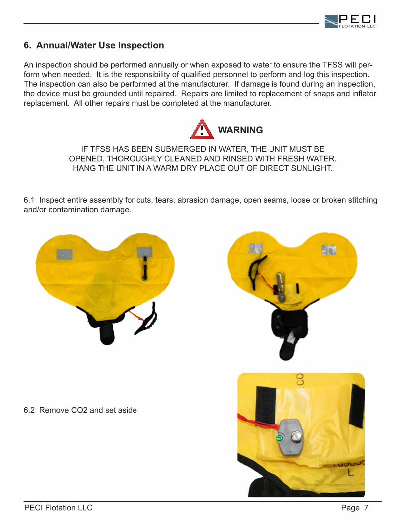
6.1Inspectentireassemblyforcuts,tears,abrasiondamage,openseams,looseorbrokenstitchingand/orcontaminationdamage.
6.2RemoveCO2andsetaside
IFTFSSHASBEENSUBMERGEDINWATER,THEUNITMUSTBEOPENED,THOROUGHLYCLEANEDANDRINSEDWITHFRESHWATER.HANGTHEUNITINAWARMDRYPLACEOUTOFDIRECTSUNLIGHT.
WARNING
PECI Flotation LLC Page 8
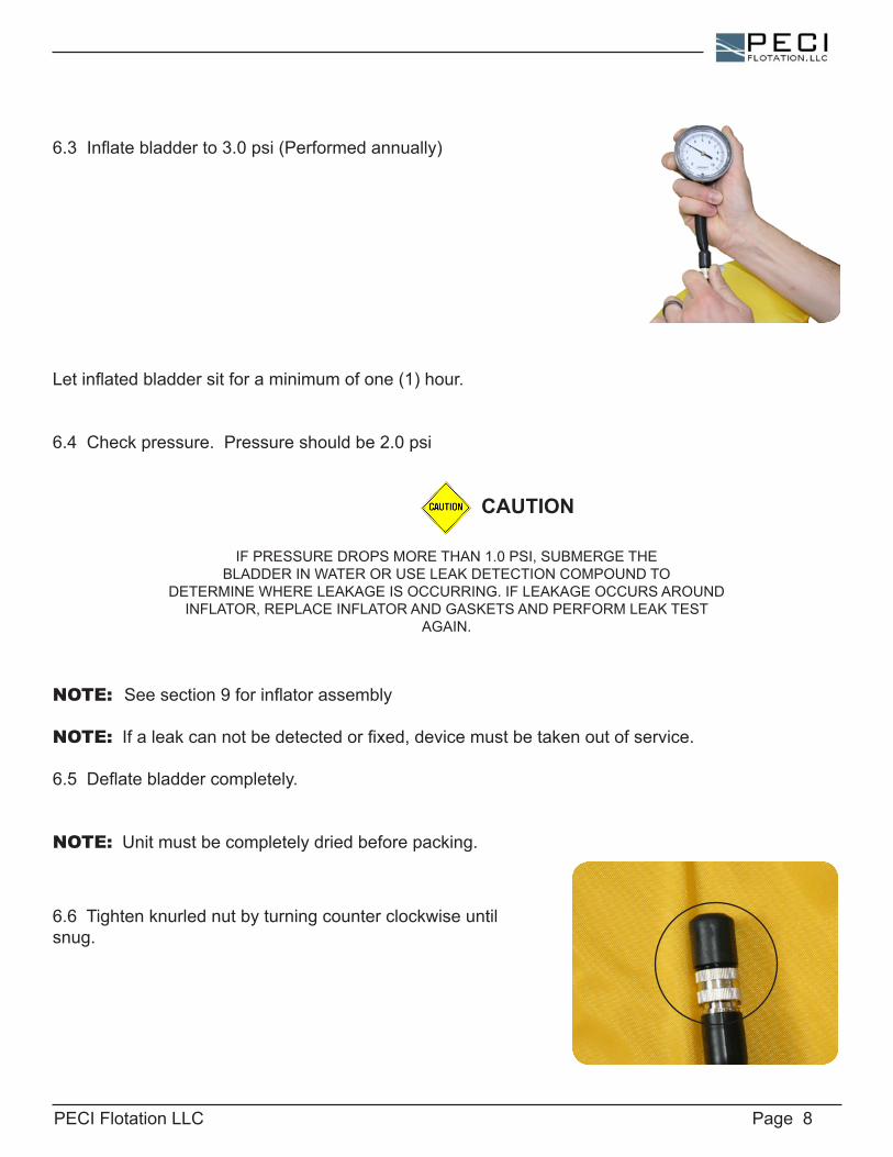
6.3Inflatebladderto3.0psi(Performedannually)
Letinflatedbladdersitforaminimumofone(1)hour.
6.4Checkpressure.Pressureshouldbe2.0psi
NOTE: Seesection9forinflatorassembly
NOTE:Ifaleakcannotbedetectedorfixed,devicemustbetakenoutofservice.
6.5Deflatebladdercompletely.
NOTE:Unitmustbecompletelydriedbeforepacking.
CAUTION
IFPRESSUREDROPSMORETHAN1.0PSI,SUBMERGETHEBLADDERINWATERORUSELEAKDETECTIONCOMPOUNDTO
DETERMINEWHERELEAKAGEISOCCURRING.IFLEAKAGEOCCURSAROUNDINFLATOR,REPLACEINFLATORANDGASKETSANDPERFORMLEAKTEST
AGAIN.
6.6Tightenknurlednutbyturningcounterclockwiseuntilsnug.
PECI Flotation LLC Page 9
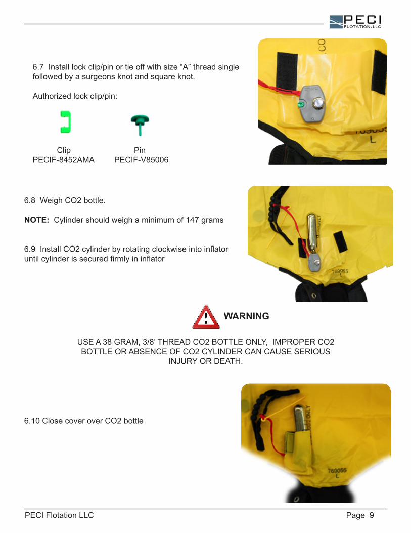
6.7Installlockclip/pinortieoffwithsize“A”threadsinglefollowedbyasurgeonsknotandsquareknot.
Authorizedlockclip/pin:
Clip PinPECIF-8452AMA PECIF-V85006
6.8WeighCO2bottle.
NOTE: Cylindershouldweighaminimumof147grams
6.9InstallCO2cylinderbyrotatingclockwiseintoinflatoruntilcylinderissecuredfirmlyininflator
6.10ClosecoveroverCO2bottle
USEA38GRAM,3/8’THREADCO2BOTTLEONLY,IMPROPERCO2BOTTLEORABSENCEOFCO2CYLINDERCANCAUSESERIOUS
INJURYORDEATH.
WARNING
PECI Flotation LLC Page 10
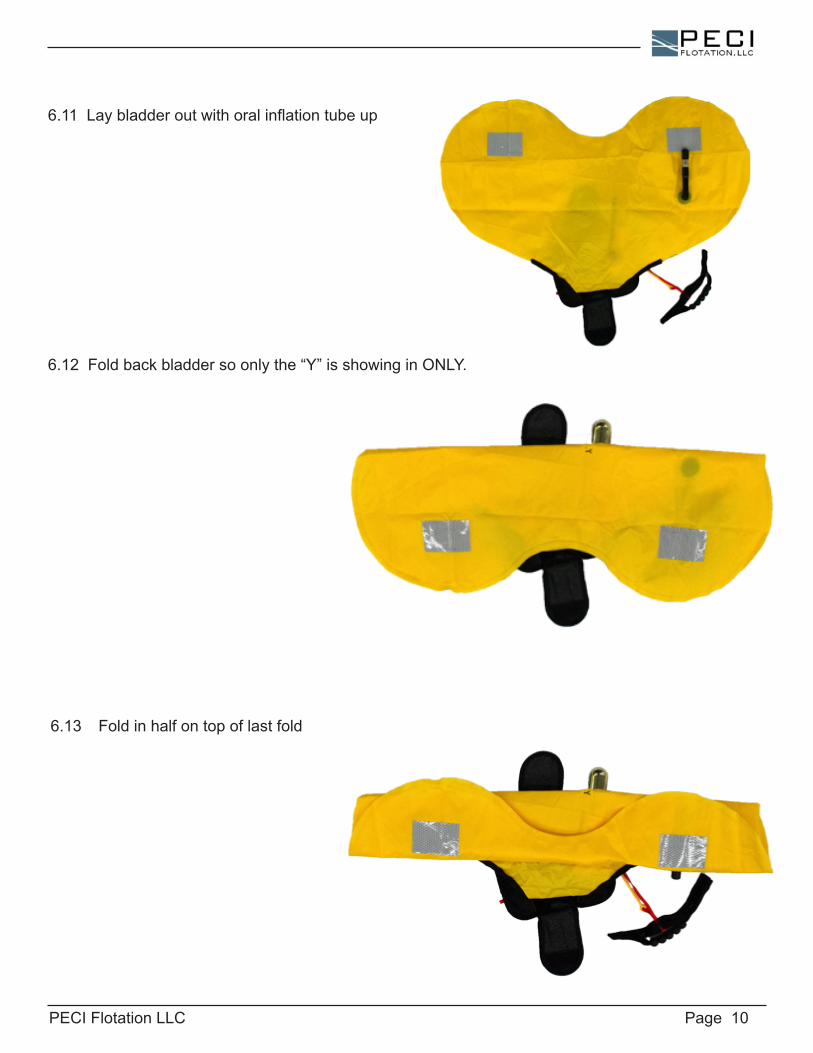
6.12Foldbackbladdersoonlythe“Y”isshowinginONLY.
6.13 Fold in half on top of last fold
6.11Laybladderoutwithoralinflationtubeup
PECI Flotation LLC Page 11
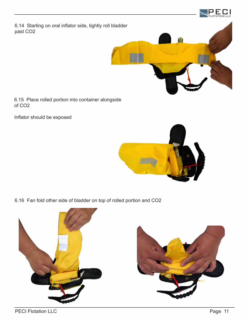
6.14Startingonoralinflatorside,tightlyrollbladderpastCO2
6.15 Place rolled portion into container alongside ofCO2
Inflatorshouldbeexposed
6.16FanfoldothersideofbladderontopofrolledportionandCO2

PECI Flotation LLC Page 12
6.17Foldtopflapontopofbottomflapandsecure velcro
6.18 Secure handle center snap
Ensurelanyardisfreeandrouteddownsideofcontainer
6.19Threada10”pieceoftypeIIIcord(gutted)orsimilarcordintotoploop
ENSUREACTIVATIONLANYARDGOESDIRECTLYTOTHEHANDLEANDNOTWRAPPEDAROUNDTHECO2CYLINDER
WARNING
PECI Flotation LLC Page 13
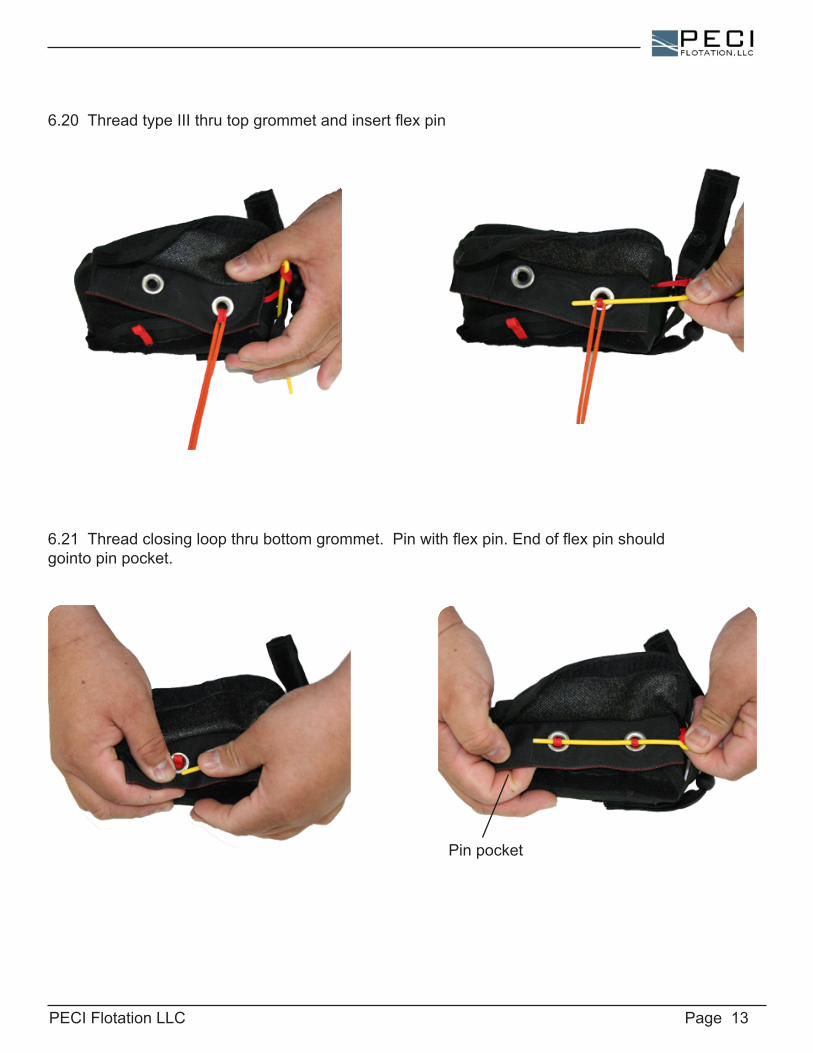
6.20ThreadtypeIIIthrutopgrommetandinsertflexpin
6.21Threadclosingloopthrubottomgrommet.Pinwithflexpin.Endofflexpinshouldgointo pin pocket.
Pin pocket
PECI Flotation LLC Page 14
7. Functional Inspection (optional)
Afunctionalinspectioncanbeperformedeverytwoyears.Functionalinspectionconsistsofmanuallyinflatingthedevicetoensureproperinflation.Itistheresponsibilityofqualifiedpersonneltoperformandlogthisinspection.Theinspectioncanalsobeperformedatthemanufacturer.Ifdam-ageisfoundduringaninspection,thedevicemustbegroundeduntilrepaired.Repairsarelimitedtoreplacementofsnapsandinflatorreplacement.Allotherrepairsmustbecompletedatthemanufacturer.
8. Service LifeTherecommendedservicelifeisfive(5)years.AfterfiveyearsofusePECIrecommendsreplace-mentofthedevice
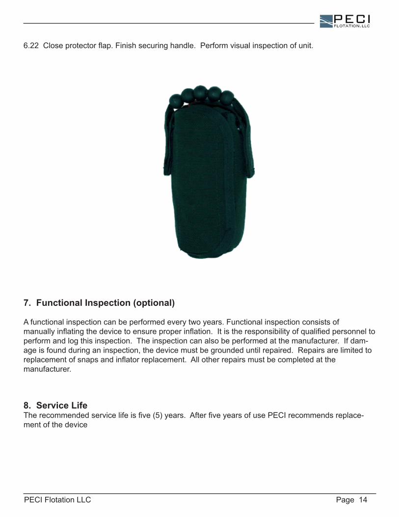
6.22Closeprotectorflap.Finishsecuringhandle.Performvisualinspectionofunit.
PECI Flotation LLC Page 15
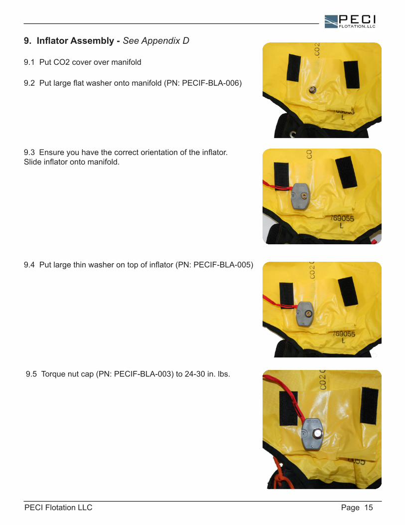
9. Inflator Assembly - See Appendix D
9.1PutCO2coverovermanifold
9.2Putlargeflatwasherontomanifold(PN:PECIF-BLA-006)
9.3 Ensureyouhavethecorrectorientationoftheinflator.Slideinflatorontomanifold.
9.4Putlargethinwasherontopofinflator(PN:PECIF-BLA-005)
9.5Torquenutcap(PN:PECIF-BLA-003)to24-30in.lbs.
PECI Flotation LLC Page 16
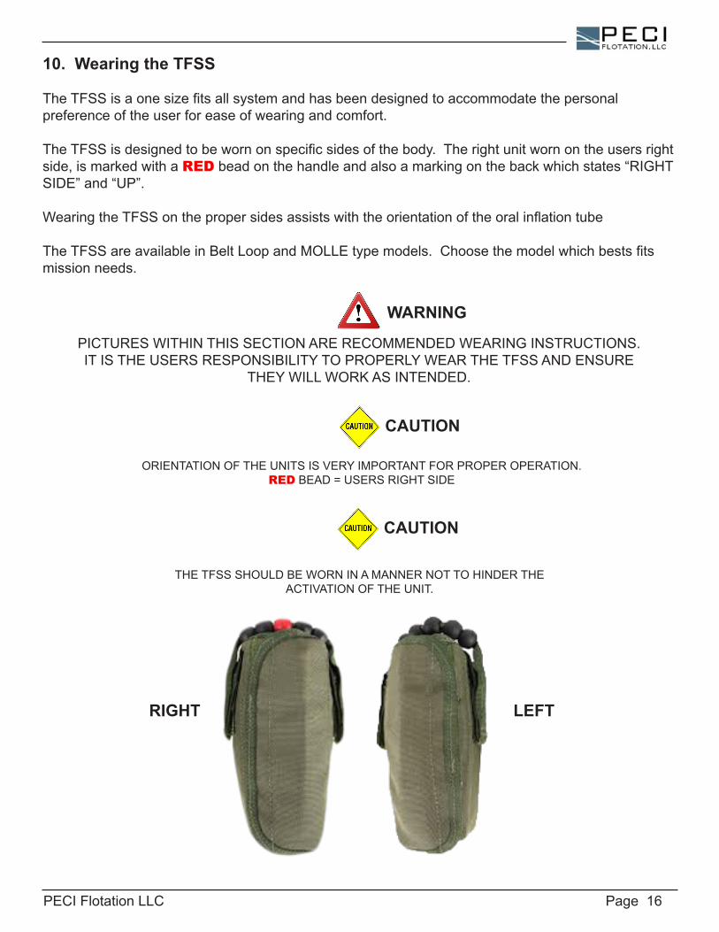
10. Wearing the TFSS
TheTFSSisaonesizefitsallsystemandhasbeendesignedtoaccommodatethepersonalpreferenceoftheuserforeaseofwearingandcomfort.
TheTFSSisdesignedtobewornonspecificsidesofthebody.Therightunitwornontheusersrightside,ismarkedwithaREDbeadonthehandleandalsoamarkingonthebackwhichstates“RIGHTSIDE”and“UP”.
WearingtheTFSSonthepropersidesassistswiththeorientationoftheoralinflationtube
TheTFSSareavailableinBeltLoopandMOLLEtypemodels.Choosethemodelwhichbestsfitsmissionneeds.
CAUTION
CAUTION
ORIENTATIONOFTHEUNITSISVERYIMPORTANTFORPROPEROPERATION.REDBEAD=USERSRIGHTSIDE
THETFSSSHOULDBEWORNINAMANNERNOTTOHINDERTHEACTIVATIONOFTHEUNIT.
PICTURESWITHINTHISSECTIONARERECOMMENDEDWEARINGINSTRUCTIONS.ITISTHEUSERSRESPONSIBILITYTOPROPERLYWEARTHETFSSANDENSURE
THEYWILLWORKASINTENDED.
WARNING
RIGHT LEFT
PECI Flotation LLC Page 17
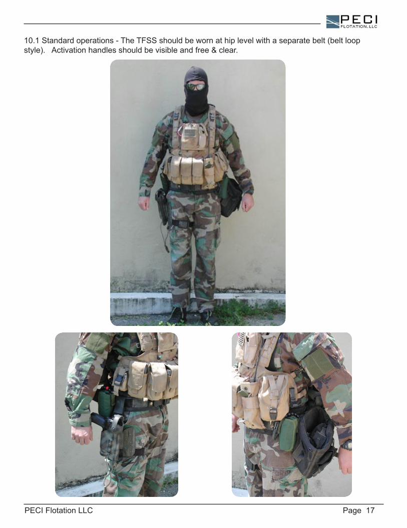
10.1Standardoperations-TheTFSSshouldbewornathiplevelwithaseparatebelt(beltloopstyle).Activationhandlesshouldbevisibleandfree&clear.
PECI Flotation LLC Page 18
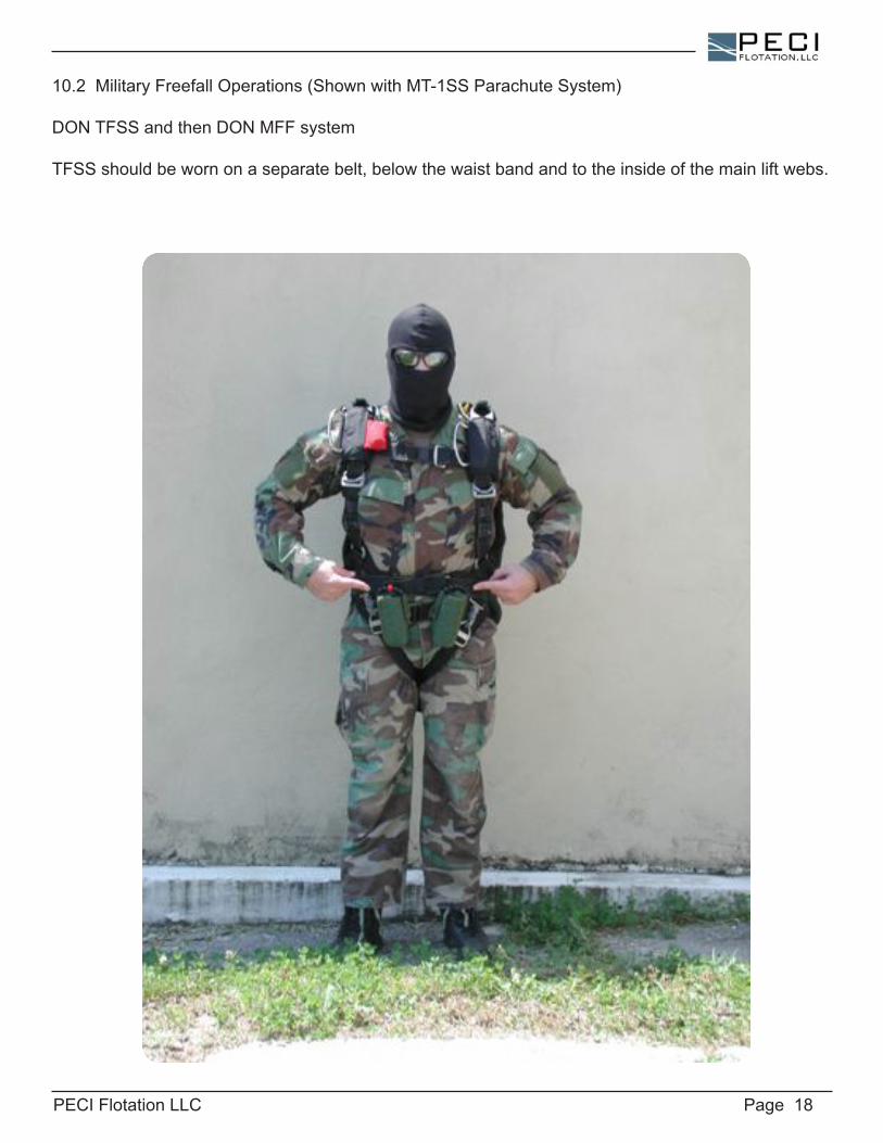
10.2MilitaryFreefallOperations(ShownwithMT-1SSParachuteSystem)
DONTFSSandthenDONMFFsystem
TFSSshouldbewornonaseparatebelt,belowthewaistbandandtotheinsideofthemainliftwebs.

PECI Flotation LLC Page 19
10.3StaticLineOperations
DONTFSSandthenDONparachutesystem
TheTFSSshouldbewornonaseparatebelt,placedtotheinsideofthemainliftwebsasshown.ThereserveparachutewillbewornabovetheTFSS.
PECI Flotation LLC Page 20
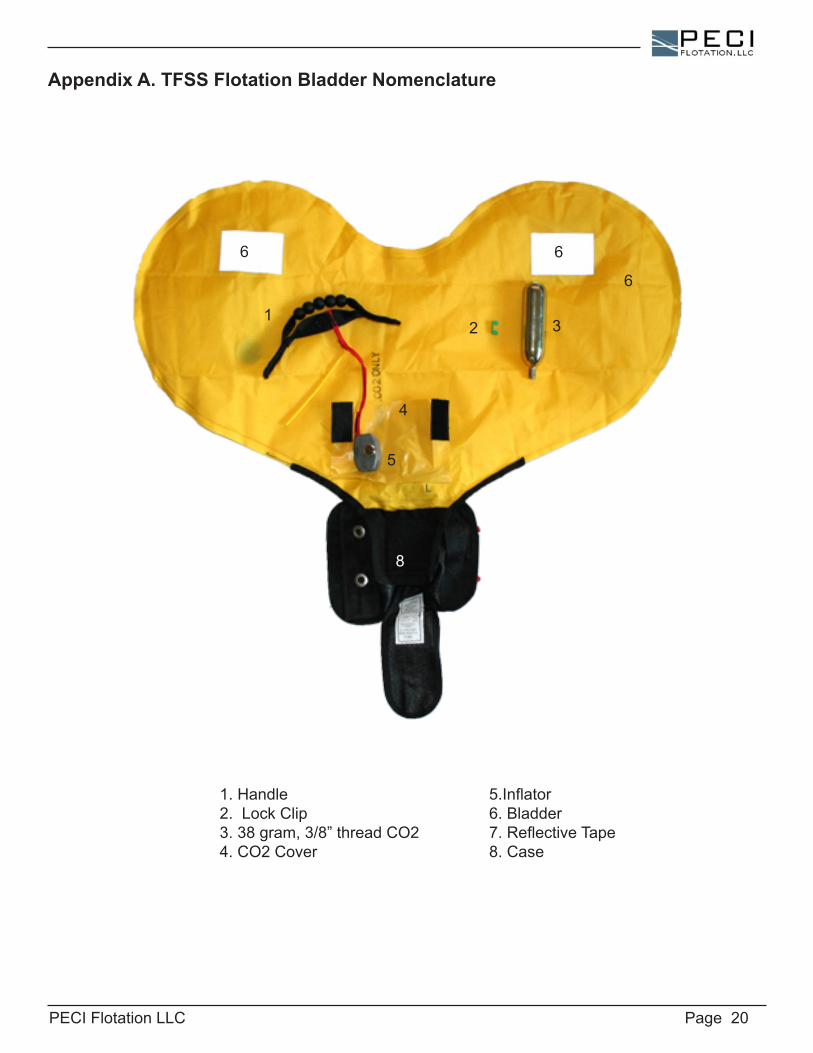
1.Handle2. Lock Clip3.38gram,3/8”threadCO24.CO2Cover
5.Inflator6. Bladder7.ReflectiveTape8. Case
Appendix A. TFSS Flotation Bladder Nomenclature
321
4
6
66
8
5
PECI Flotation LLC Page 21
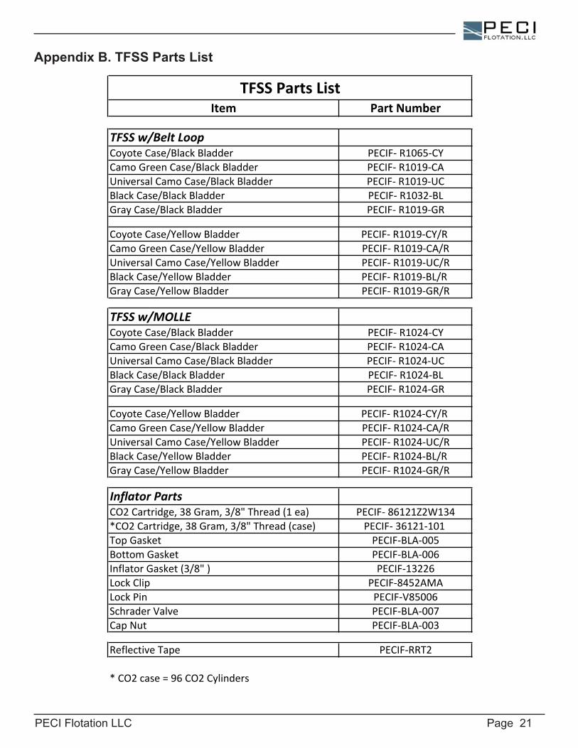
Appendix B. TFSS Parts List
Item Part Number
TFSS w/Belt LoopCoyote Case/Black Bladder PECIF-‐ R1065-‐CYCamo Green Case/Black Bladder PECIF-‐ R1019-‐CAUniversal Camo Case/Black Bladder PECIF-‐ R1019-‐UCBlack Case/Black Bladder PECIF-‐ R1032-‐BLGray Case/Black Bladder PECIF-‐ R1019-‐GR
Coyote Case/Yellow Bladder PECIF-‐ R1019-‐CY/R Camo Green Case/Yellow Bladder PECIF-‐ R1019-‐CA/RUniversal Camo Case/Yellow Bladder PECIF-‐ R1019-‐UC/RBlack Case/Yellow Bladder PECIF-‐ R1019-‐BL/R Gray Case/Yellow Bladder PECIF-‐ R1019-‐GR/R
TFSS w/MOLLECoyote Case/Black Bladder PECIF-‐ R1024-‐CYCamo Green Case/Black Bladder PECIF-‐ R1024-‐CAUniversal Camo Case/Black Bladder PECIF-‐ R1024-‐UCBlack Case/Black Bladder PECIF-‐ R1024-‐BLGray Case/Black Bladder PECIF-‐ R1024-‐GR
Coyote Case/Yellow Bladder PECIF-‐ R1024-‐CY/R Camo Green Case/Yellow Bladder PECIF-‐ R1024-‐CA/RUniversal Camo Case/Yellow Bladder PECIF-‐ R1024-‐UC/RBlack Case/Yellow Bladder PECIF-‐ R1024-‐BL/R Gray Case/Yellow Bladder PECIF-‐ R1024-‐GR/R
Inflator PartsCO2 Cartridge, 38 Gram, 3/8" Thread (1 ea) PECIF-‐ 86121Z2W134*CO2 Cartridge, 38 Gram, 3/8" Thread (case) PECIF-‐ 36121-‐101 Top Gasket PECIF-‐BLA-‐005Bottom Gasket PECIF-‐BLA-‐006Inflator Gasket (3/8" ) PECIF-‐13226Lock Clip PECIF-‐8452AMALock Pin PECIF-‐V85006Schrader Valve PECIF-‐BLA-‐007Cap Nut PECIF-‐BLA-‐003
Reflective Tape PECIF-‐RRT2
* CO2 case = 96 CO2 Cylinders
TFSS Parts List
PECI Flotation LLC Page 22
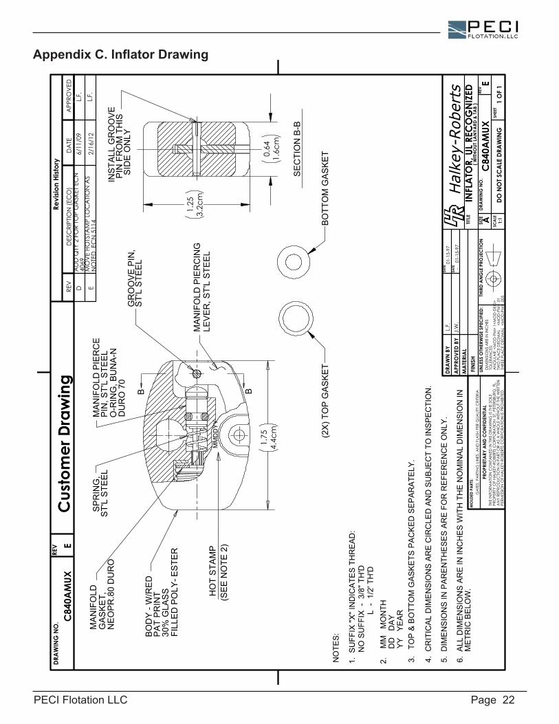
Appendix C. Inflator Drawing
1.75
4.4c
m
1.25
3.2c
m
0.64
1.6c
m
INS
TALL
GR
OO
VE
PIN
FR
OM
TH
ISS
IDE
ON
LYB B
MM
DD
YY
SE
CTI
ON
B-B
HO
T S
TAM
P
(SE
E N
OTE
2)
MA
NIF
OLD
PIE
RC
EP
IN, S
T'L
STE
EL
O-R
ING
, BU
NA
-N
DU
RO
70
BO
DY
- W
/RE
DP
AT
PR
INT
30%
GLA
SS
FILL
ED
PO
LY-E
STE
R
SP
RIN
G,
ST'
L S
TEE
L
MA
NIF
OLD
PIE
RC
ING
LEV
ER
, ST'
L S
TEE
L
GR
OO
VE
PIN
,S
T'L
STE
EL
MA
NIF
OLD
GA
SK
ET,
NE
OP
R.8
0 D
UR
O
(2X
) TO
P G
AS
KE
TB
OTT
OM
GA
SK
ET
NO
TES
:
1.
SU
FFIX
"X" I
ND
ICA
TES
TH
RE
AD
:
NO
SU
FFIX
- 3
/8" T
H'D
L -
1/2
' TH
'D
2.
MM
M
ON
TH
D
D
DA
Y
Y
Y
YE
AR
3.
TOP
& B
OTT
OM
GA
SK
ETS
PA
CK
ED
SE
PA
RA
TELY
.
4. C
RIT
ICA
L D
IME
NS
ION
S A
RE
CIR
CLE
D A
ND
SU
BJE
CT
TO IN
SP
EC
TIO
N.
5. D
IME
NS
ION
S IN
PA
RE
NTH
ES
ES
AR
E F
OR
RE
FER
EN
CE
ON
LY.
6. A
LL D
IME
NS
ION
S A
RE
IN IN
CH
ES
WIT
H T
HE
NO
MIN
AL
DIM
EN
SIO
N IN
ME
TRIC
BE
LOW
.Halkey-Roberts
Revi
sion
Hist
ory
DES
CRI
PTIO
N (E
CO
)D
ATE
APP
ROV
EDRE
V
TITLE
SIZE
DRA
WIN
G N
O.
REV
SCA
LESH
EET
DRA
WN
BY
APP
ROVE
D BY
MA
TERI
AL
FIN
ISH
DATE
THE
INFO
RMA
TION
CO
NTA
INED
IN T
HIS
DRA
WIN
G IS
THE
SO
LE
PRO
PERT
Y O
F HA
LKEY
-RO
BERT
S C
ORP
ORA
TION
ST.
PET
ERSB
URG
, FL.
AN
Y RE
PRO
DUC
TION
IN P
ART
OR
AS
A W
HOLE
WITH
OUT
THE
WRI
TTEN
PE
RMIS
SIO
N O
F HA
LKEY
-RO
BERT
S C
ORP
ORA
TION
IS P
ROHI
BITE
D.
PRO
PRIE
TARY
AN
D C
ON
FIDE
NTIA
LD
IMEN
SIO
NS
ARE
IN IN
CHE
STO
LERA
NC
ES:
AN
GUL
AR:
<M
OD
-PM
> 1<
MO
D-D
EG>
TW
O P
LAC
E D
ECIM
AL
<M
OD
-PM
> .0
1TH
REE
PLA
CE
DEC
IMA
L <
MO
D-P
M>
.005
UNLE
SS O
THER
WIS
E SP
ECIF
IED:
THIR
D A
NG
LE P
ROJE
CTIO
NG
ATE
S, P
ART
ING
LIN
ES, A
ND
FLA
SH P
ER Q
UALIT
Y C
RITE
RIA
DRA
WIN
G N
O.
REV
INFL
ATO
R, U
L REC
OG
NIZ
EDC
840A
MUX
E1:
11
OF
1
L.F.
01-1
5-97
J.W
.-
DO N
OT S
CA
LE D
RAW
ING
A
EC
840A
MUX
Cus
tom
er D
raw
ing
DATE
MO
LDED
PA
RTS:
L.F.L.F.
2/16
/12
6/11
/09
MO
VE
HOTS
TAM
P LO
CA
TION
AS
NO
TED
EC
N 5
114
AD
D Q
TY 2
FO
R TO
P G
ASK
ET E
CN
4069
ED
01-1
5-97
( WITH
OUT
LAN
YARD
& TA
B )
PECI Flotation LLC Page 23
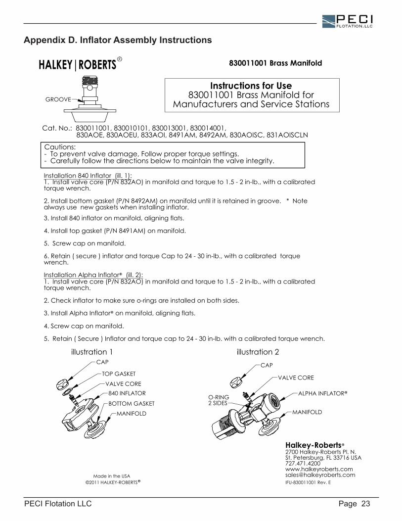
Appendix D. Inflator Assembly Instructions
GROOVE
MANIFOLD
ALPHA INFLATOR®
CAP
O-RING 2 SIDES
VALVE CORE
Halkey-Roberts®2700 Halkey-Roberts Pl. N.St. Petersburg, FL 33716 [email protected] in the USA
MANIFOLD
BOTTOM GASKET
840 INFLATOR
TOP GASKET
CAP
VALVE CORE
Instructions for Use830011001 Brass Manifold for
Manufacturers and Service Stations
Installation 840 Inflator (ill. 1):1. Install valve core (P/N 832AO) in manifold and torque to 1.5 - 2 in-lb., with a calibrated torque wrench.
2. Install bottom gasket (P/N 8492AM) on manifold until it is retained in groove. * Note always use new gaskets when installing inflator. 3. Install 840 inflator on manifold, aligning flats.
4. Install top gasket (P/N 8491AM) on manifold.
5. Screw cap on manifold.
6. Retain ( secure ) inflator and torque Cap to 24 - 30 in-lb., with a calibrated torque wrench. Installation Alpha Inflator® (ill. 2):1. Install valve core (P/N 832AO) in manifold and torque to 1.5 - 2 in-lb., with a calibrated torque wrench.
2. Check inflator to make sure o-rings are installed on both sides.
3. Install Alpha Inflator® on manifold, aligning flats.
4. Screw cap on manifold.
5. Retain ( Secure ) Inflator and torque cap to 24 - 30 in-lb. with a calibrated torque wrench.
Cat. No.: 830011001, 830010101, 830013001, 830014001, 830AOE, 830AOEU, 833AOI, 8491AM, 8492AM, 830AOISC, 831AOISCLN
Cautions:- To prevent valve damage, Follow proper torque settings.- Carefully follow the directions below to maintain the valve integrity.
HALKEY|ROBERTS 830011001 Brass Manifold
illustration 1 illustration 2
IFU-830011001 Rev. E
R
©2011 HALKEY-ROBERTS®