Embed Size (px)
Citation preview
Dissolved Air FlotationBy Zerihun Alemayehu
Water Treatment
Flotation
Flotation is described as a gravity separation process in which gas bubbles attach to solid particles to cause the apparent density of the bubble-solid agglomerates to be less than that of the water, thereby allowing the agglomerate to float to the surface.
Flotation is employed mainly for the treatment of nutrient-rich reservoir waters that may have heavy algal blooms and for low-turbidity, low-alkalinity colored waters.
Types of Flotation
Different methods of producing gas bubbles give rise to different types of flotation processes.
These are electrolytic flotation, dispersed air flotation, and dissolved air flotation.
The basis of electrolytic or electroflotation is the generation of bubbles of hydrogen and oxygen in a dilute aqueous solution by passing a dc current between two electrodes.
The application of electrolytic flotation has been restricted mainly to sludge thickening and small wastewater treatment plants in the range 10 to 20 m3/h (50,000 to 100,000 gpd) and has limited application to drinking water treatment.
Types of Flotation
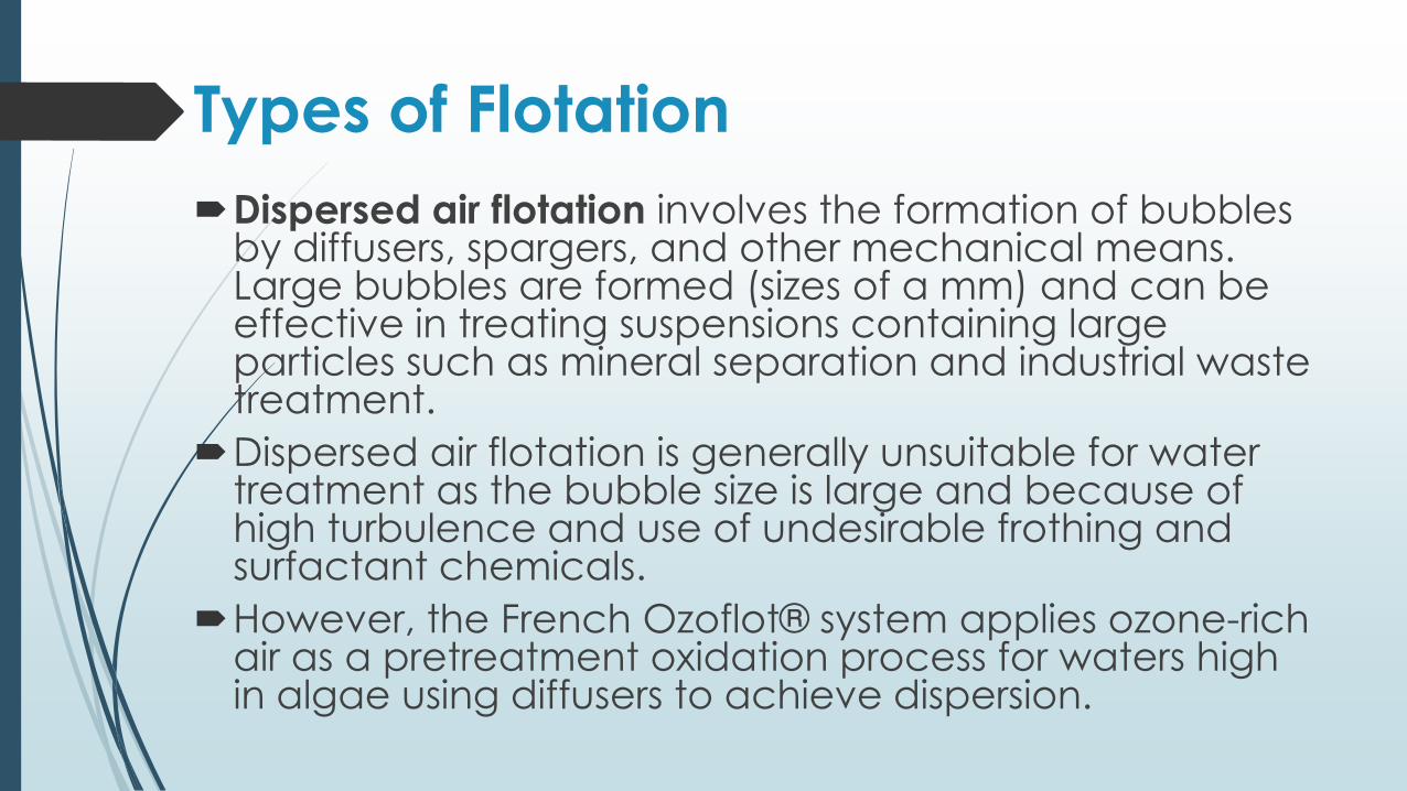
Dispersed air flotation involves the formation of bubbles by diffusers, spargers, and other mechanical means. Large bubbles are formed (sizes of a mm) and can be effective in treating suspensions containing large particles such as mineral separation and industrial waste treatment.
Dispersed air flotation is generally unsuitable for water treatment as the bubble size is large and because of high turbulence and use of undesirable frothing and surfactant chemicals.
However, the French Ozoflot® system applies ozone-rich air as a pretreatment oxidation process for waters high in algae using diffusers to achieve dispersion.
Types of Flotation
In dissolved air flotation, air bubbles are
produced by the reduction in pressure of a
water stream saturated with air.
The three main types of dissolved air flotation
are vacuum flotation, micro-flotation, and
pressure flotation.
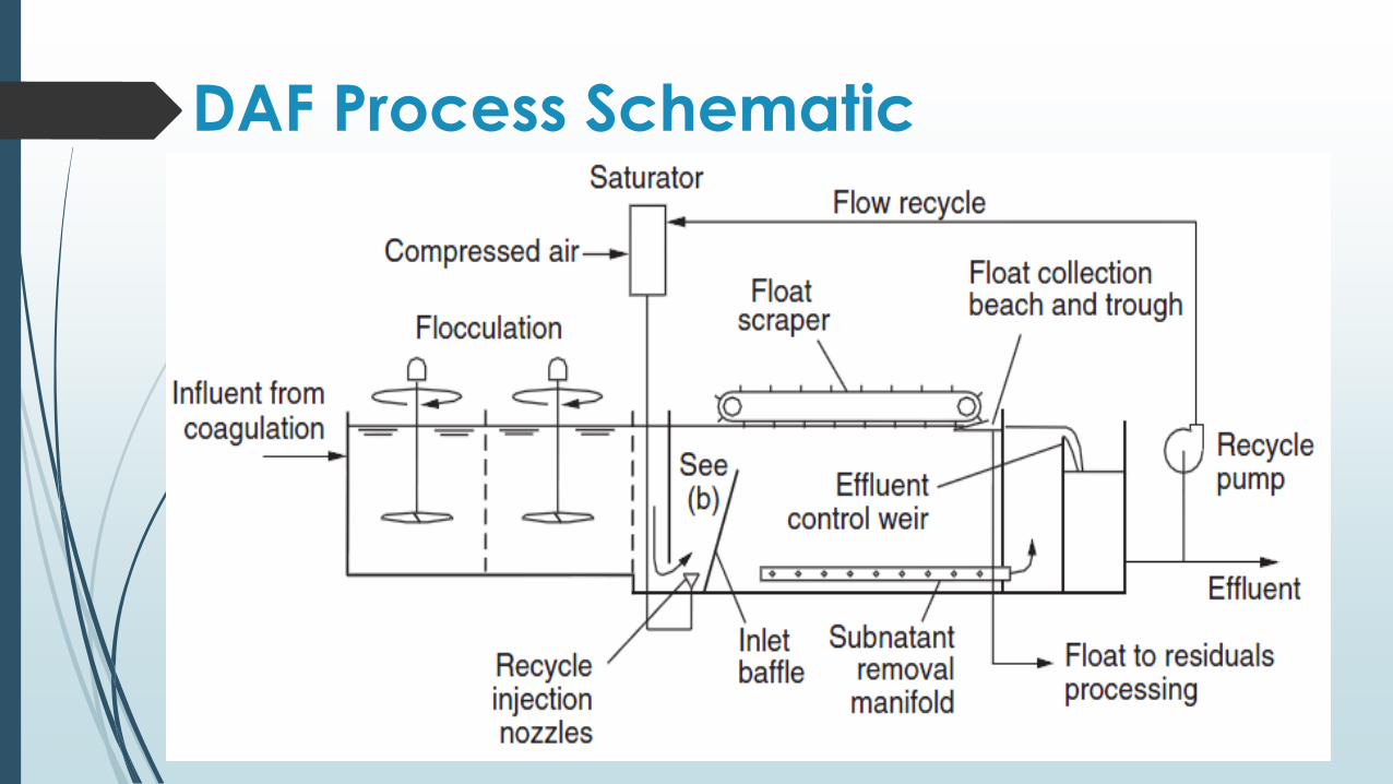
DAF Process Schematic
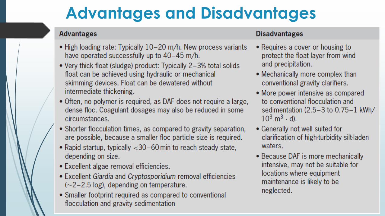
Advantages and Disadvantages
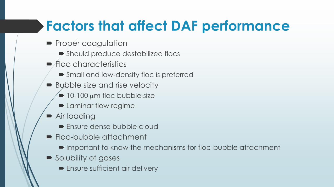
Factors that affect DAF performance Proper coagulation
Should produce destabilized flocs
Floc characteristics
Small and low-density floc is preferred
Bubble size and rise velocity
10-100 mm floc bubble size
Laminar flow regime
Air loading
Ensure dense bubble cloud
Floc-bubble attachment
Important to know the mechanisms for floc-bubble attachment
Solubility of gases
Ensure sufficient air delivery
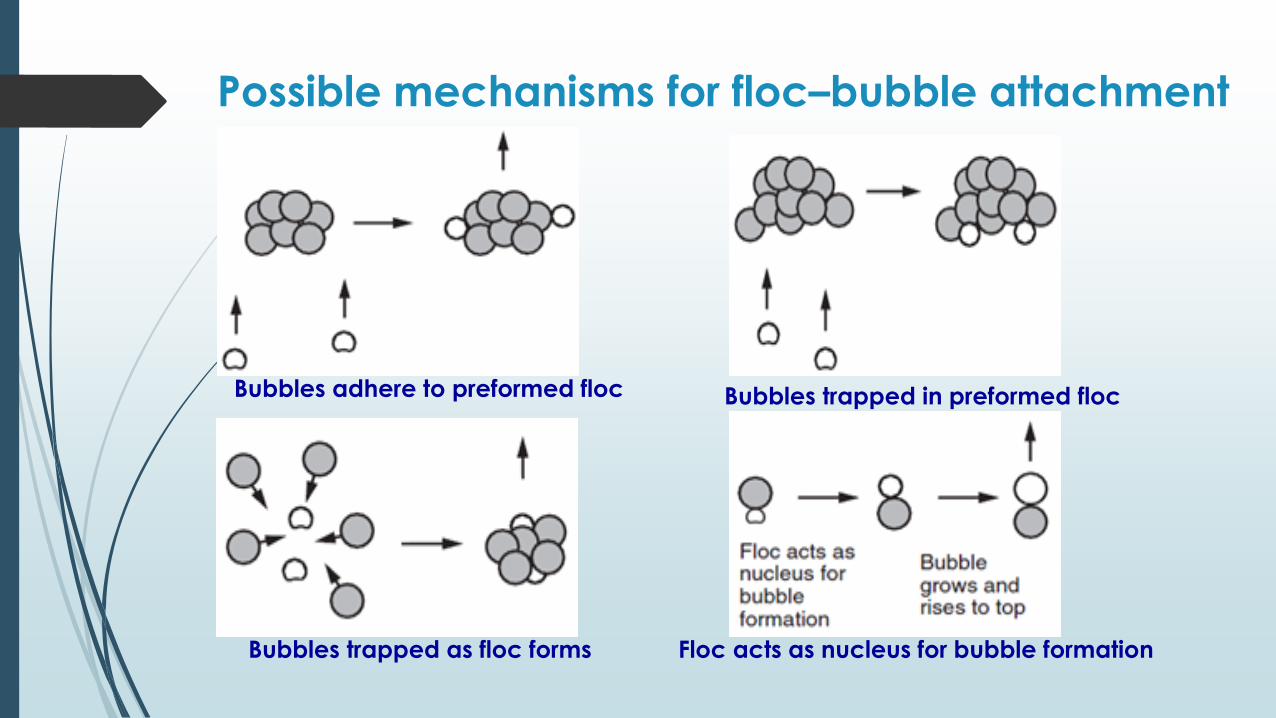
Possible mechanisms for floc–bubble attachment
Bubbles adhere to preformed floc Bubbles trapped in preformed floc
Bubbles trapped as floc forms Floc acts as nucleus for bubble formation
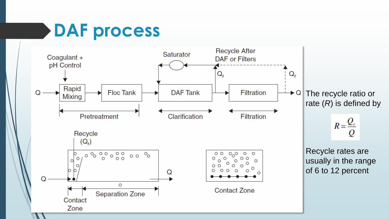
DAF process
The recycle ratio or
rate (R) is defined by
Recycle rates are
usually in the range
of 6 to 12 percent
Air Bubbles
Saturator gauge pressures are usually between 400 and 600 kPa.
The recycle flow is injected through nozzles or special valves at the bottom entrance to the contact zone. Microbubbles are produced with sizes between 10 and 100 μm.
Conventional DAF processes hydraulic load: 5 to 15 m/h.
High-rate DAF processes hydraulic load:15 to 30 m/h
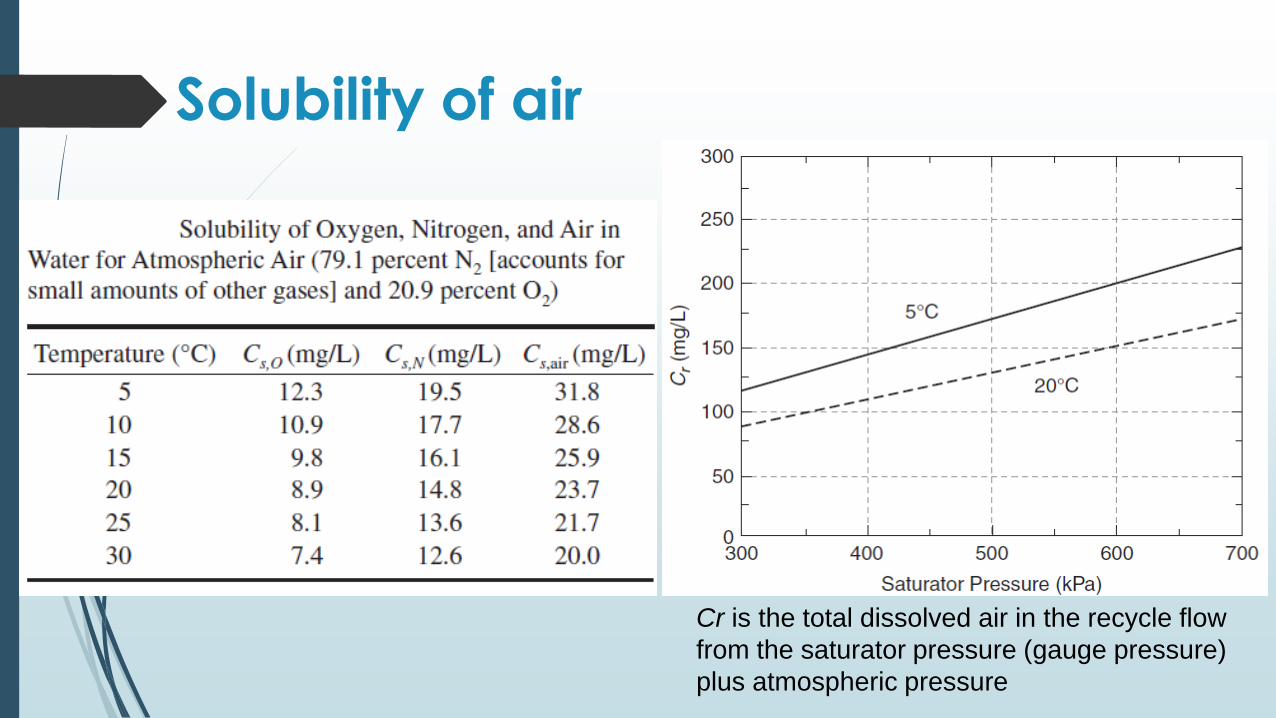
Solubility of air
Cr is the total dissolved air in the recycle flow
from the saturator pressure (gauge pressure)
plus atmospheric pressure
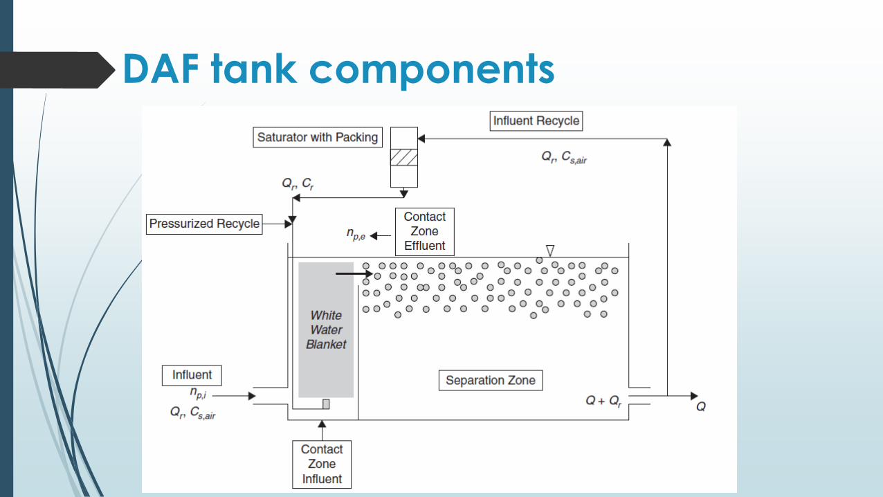
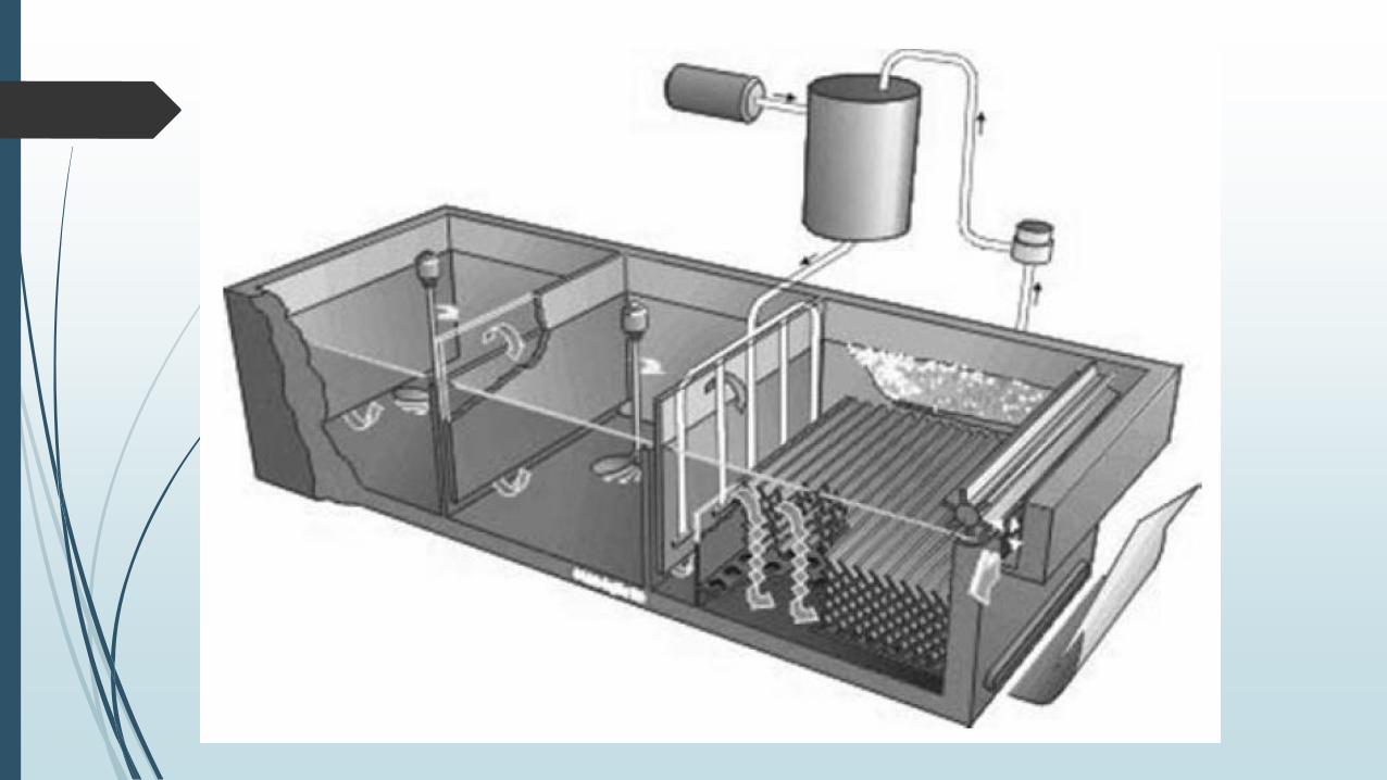
DAF tank components
Bubble Suspension in the Contact Zone
The bubble suspension (White water blanket) in
the contact zone achieves a steady state
bubble concentration arising from the
continuous input of pressurized recycle flow
(Qr) mixing with the influent water (Q) from the
flocculation tank.
There are three measures of bubble
concentrations: mass, volume, and number.
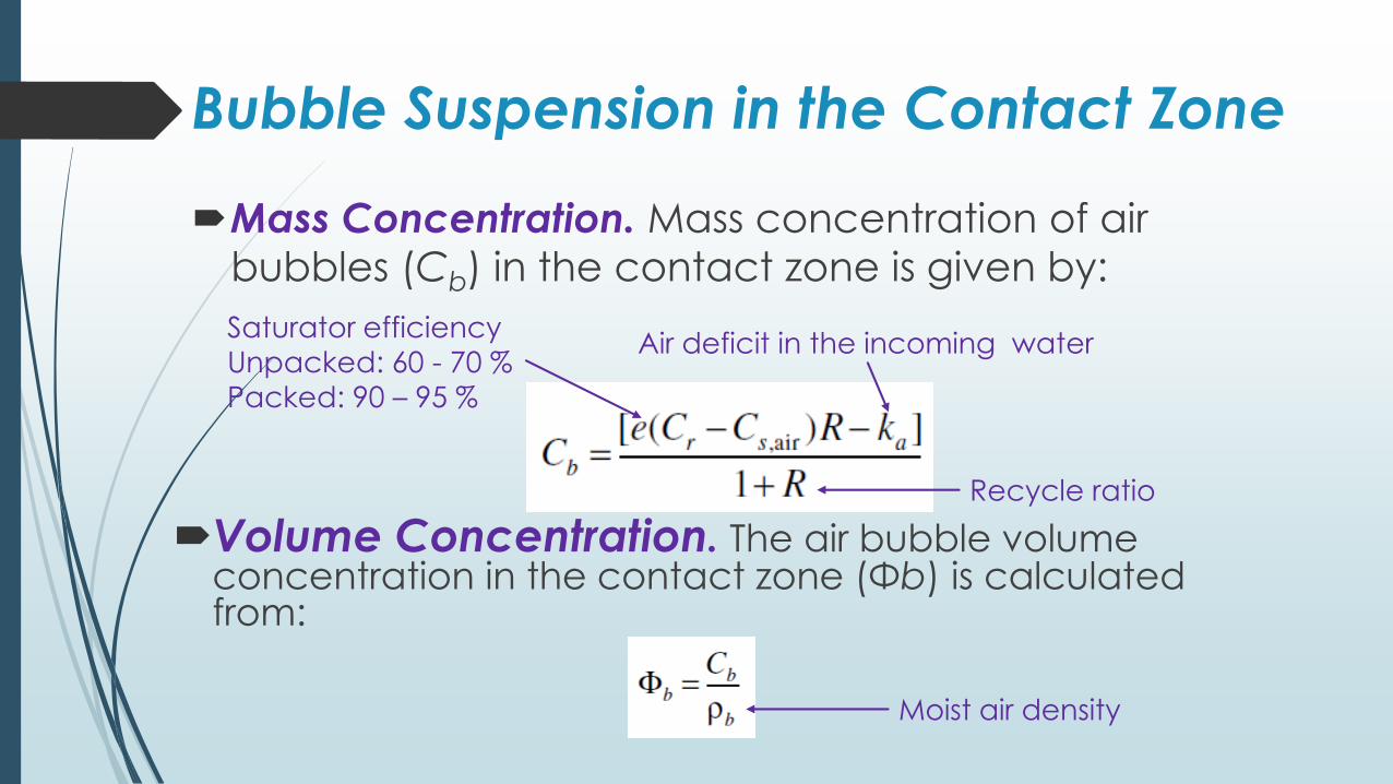
Bubble Suspension in the Contact Zone
Mass Concentration. Mass concentration of air
bubbles (Cb) in the contact zone is given by:
Air deficit in the incoming waterSaturator efficiency
Unpacked: 60 - 70 %
Packed: 90 – 95 %
Recycle ratio
Volume Concentration. The air bubble volume concentration in the contact zone (Φb) is calculated from:
Moist air density
Bubble Suspension in the Contact Zone
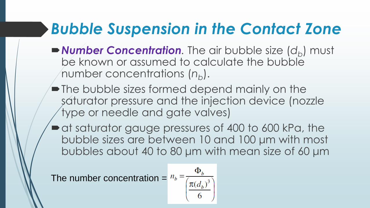
Number Concentration. The air bubble size (db) must be known or assumed to calculate the bubble number concentrations (nb).
The bubble sizes formed depend mainly on the saturator pressure and the injection device (nozzle type or needle and gate valves)
at saturator gauge pressures of 400 to 600 kPa, the bubble sizes are between 10 and 100 μm with most bubbles about 40 to 80 μm with mean size of 60 μm
The number concentration =
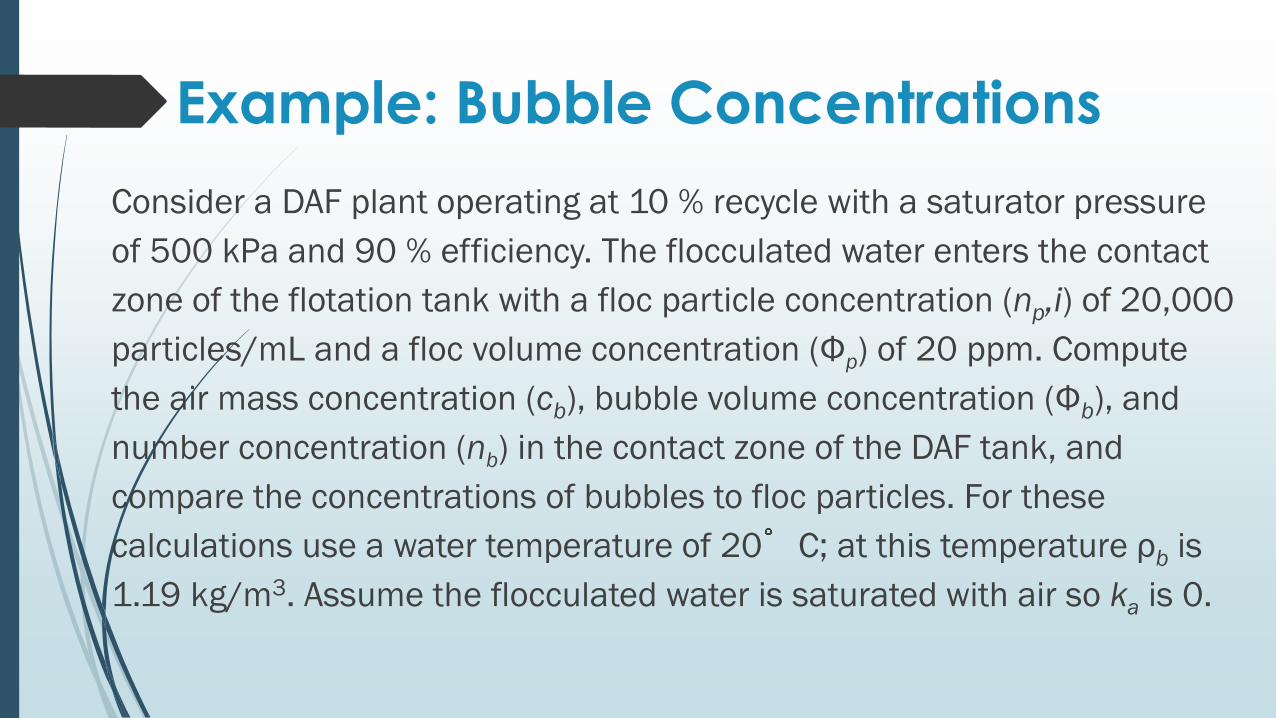
Example: Bubble Concentrations
Consider a DAF plant operating at 10 % recycle with a saturator pressure
of 500 kPa and 90 % efficiency. The flocculated water enters the contact
zone of the flotation tank with a floc particle concentration (np,i) of 20,000
particles/mL and a floc volume concentration (Φp) of 20 ppm. Compute
the air mass concentration (cb), bubble volume concentration (Φb), and
number concentration (nb) in the contact zone of the DAF tank, and
compare the concentrations of bubbles to floc particles. For these
calculations use a water temperature of 20 C; at this temperature ρb is
1.19 kg/m3. Assume the flocculated water is saturated with air so ka is 0.
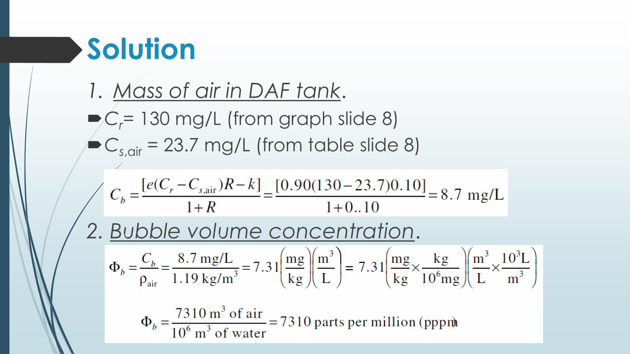
Solution
1. Mass of air in DAF tank.
Cr= 130 mg/L (from graph slide 8)
Cs,air = 23.7 mg/L (from table slide 8)
2. Bubble volume concentration.
Solution
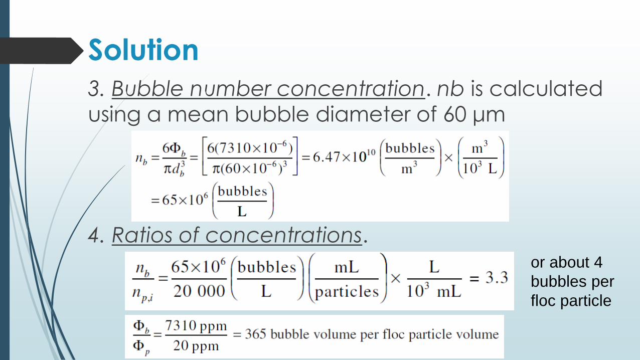
3. Bubble number concentration. nb is calculated
using a mean bubble diameter of 60 μm
4. Ratios of concentrations.or about 4
bubbles per
floc particle
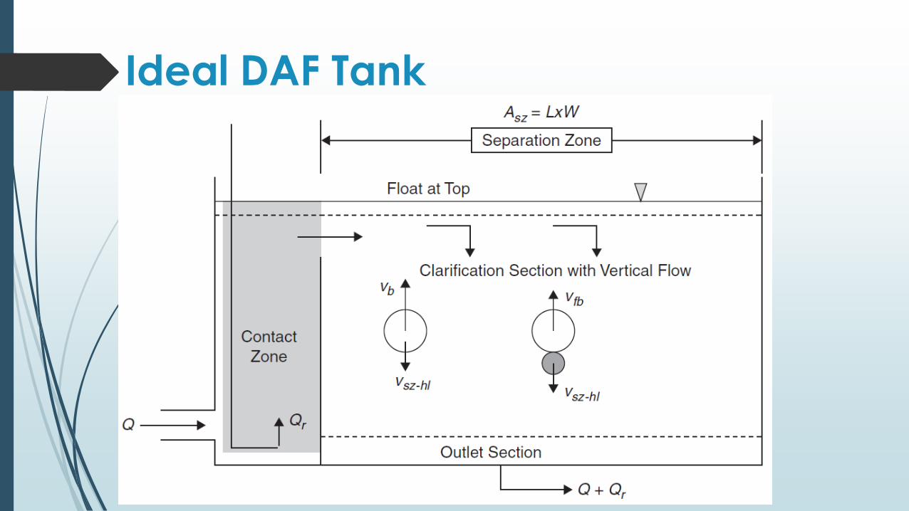
Ideal DAF Tank
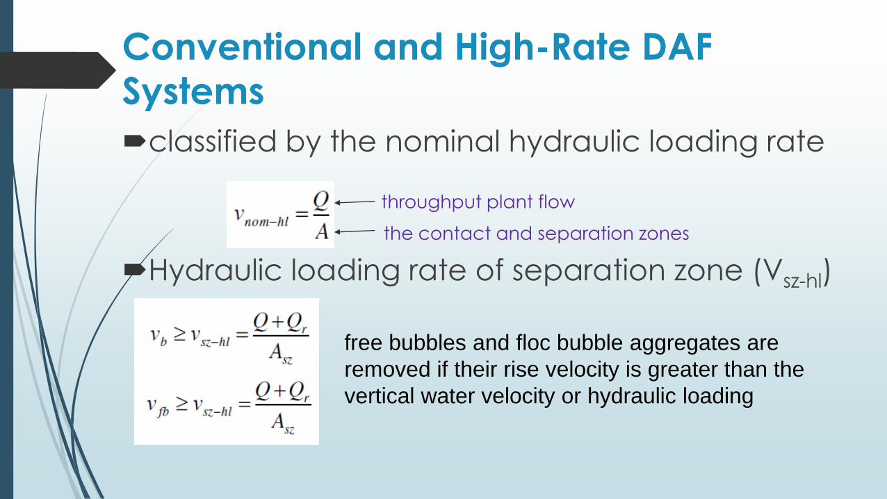
Conventional and High-Rate DAF
Systems
classified by the nominal hydraulic loading rate
the contact and separation zones
throughput plant flow
Hydraulic loading rate of separation zone (Vsz-hl)
free bubbles and floc bubble aggregates are
removed if their rise velocity is greater than the
vertical water velocity or hydraulic loading
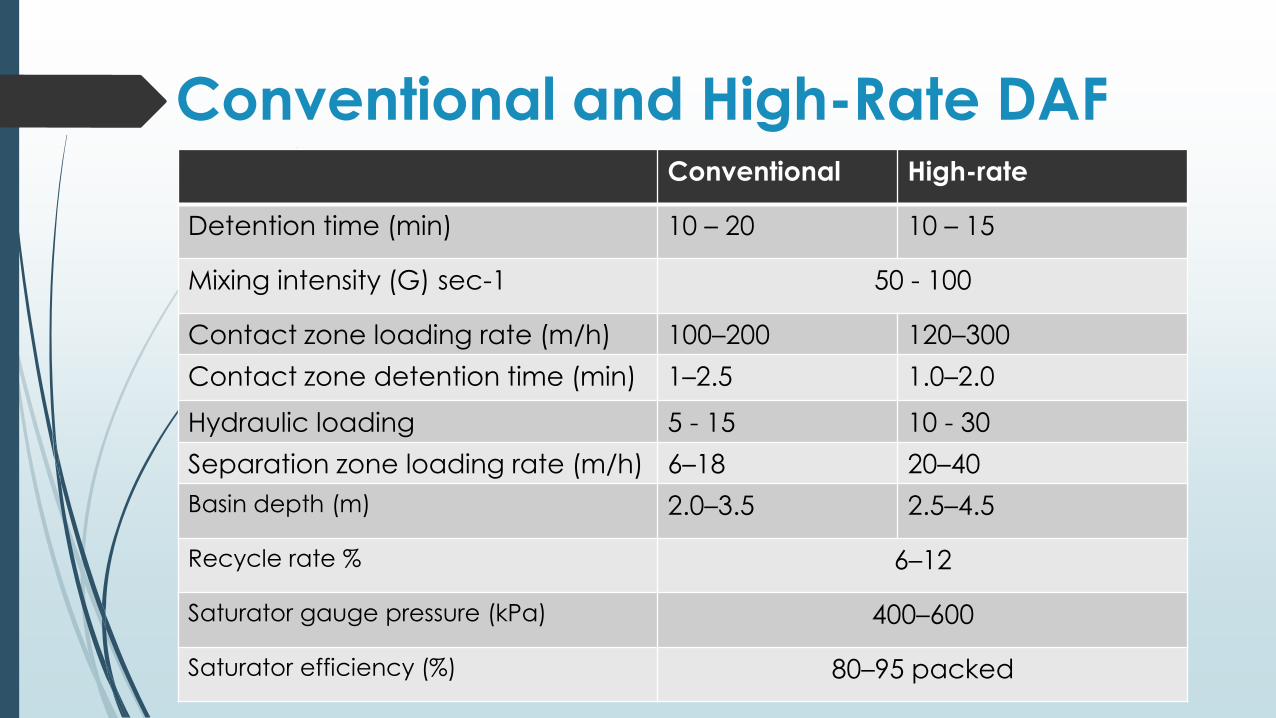
Conventional and High-Rate DAFConventional High-rate
Detention time (min) 10 – 20 10 – 15
Mixing intensity (G) sec-1 50 - 100
Contact zone loading rate (m/h) 100–200 120–300
Contact zone detention time (min) 1–2.5 1.0–2.0
Hydraulic loading 5 - 15 10 - 30
Separation zone loading rate (m/h) 6–18 20–40
Basin depth (m) 2.0–3.5 2.5–4.5
Recycle rate % 6–12
Saturator gauge pressure (kPa) 400–600
Saturator efficiency (%) 80–95 packed
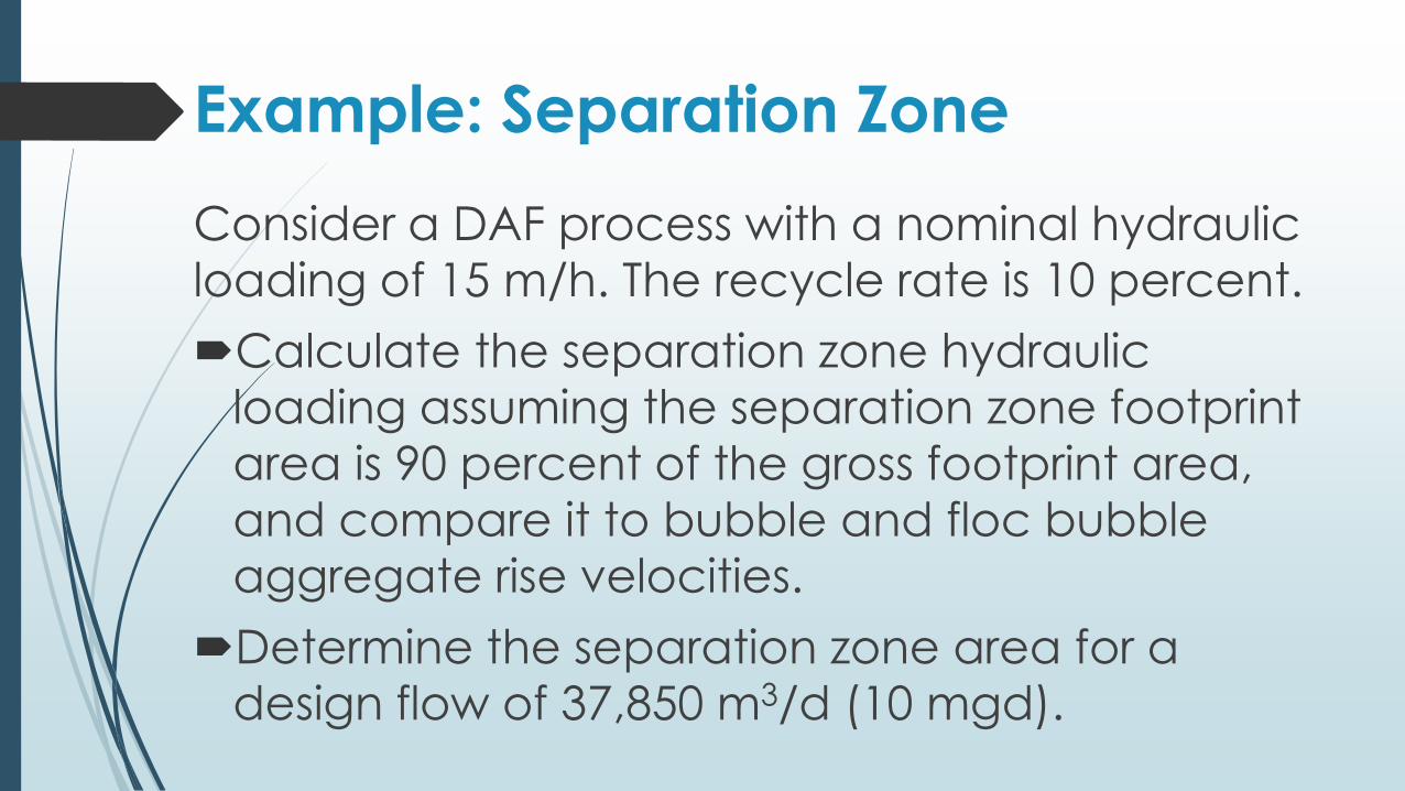
Example: Separation Zone
Consider a DAF process with a nominal hydraulic
loading of 15 m/h. The recycle rate is 10 percent.
Calculate the separation zone hydraulic
loading assuming the separation zone footprint
area is 90 percent of the gross footprint area,
and compare it to bubble and floc bubble
aggregate rise velocities.
Determine the separation zone area for a
design flow of 37,850 m3/d (10 mgd).
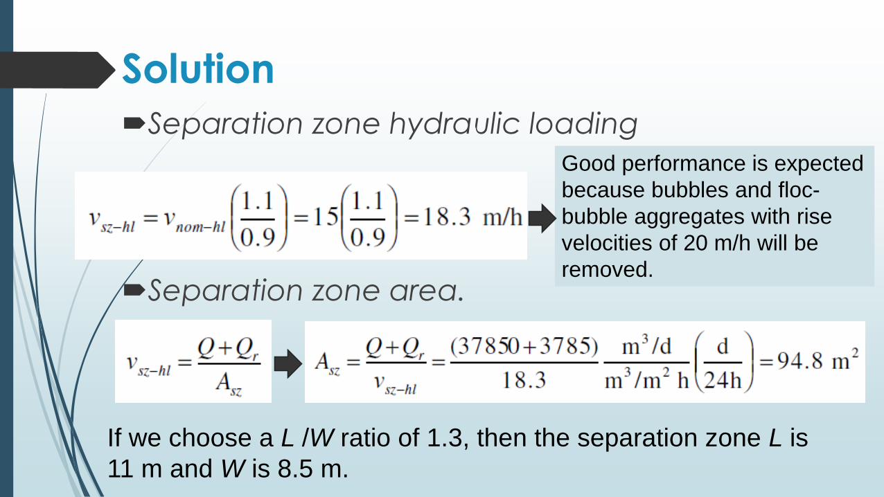
Solution
Separation zone hydraulic loading
Good performance is expected
because bubbles and floc-
bubble aggregates with rise
velocities of 20 m/h will be
removed.Separation zone area.
If we choose a L /W ratio of 1.3, then the separation zone L is
11 m and W is 8.5 m.

All the best!