Embed Size (px)
Citation preview
2
2
Table of Contents
Introduction Page 3
Safety Page 4
Pre Check / Hydraulics Page 5
Description of safety warnings Page 6
Hitching / Unhitching Page 7
Sharpening Blades Page 8
Shear Genius Page 9
Mega Bite Page 12
Shear Grab Page 14
Tractor & Telehandler Tine Grab Page 15
Tractor & Telehandler Grapple Bucket Page 16
Bag Filler Bucket Page 17
Round Neck Bag Filler Bucket Page 19
Forklift Bag Filler Bucket Page 20
Forklift Tipping Bucket Page 23
Hi-Tip Bucket Page 24
Bale Handler Page 25
Bale Grab Page 27
Bale Stacker (C320,C430) Page 29
Folding Grass Fork Page 32
Push Off Grass Fork Page 34
ProSweep Page 37
Other Attachments Page 39

3
3
Dear user, We thank you for placing your trust in our product and hope you will find your
attachment satisfactory in every way.
Taking a few minutes to read this manual will enable you to use the capabilities of
your attachment to the full while prolong its service life and ensure safe operation.
This user manual is an important document, please retain it in order to be referred to if
required. Make it available to any other users and hand it over it to any new owner in
the event of your attachment being sold on.
The illustrations and technical data shown in this document might not match your
attachment model exactly, operating conditions will nevertheless remain the same.
The user must read and understand this manual before first use.

4
4
IMPORTANT: Read this before operating any attachment
Most farm accidents can be avoided by observing simple precautions. You should read through the following precautions
before operating the equipment, and at intervals afterwards to refresh your memory.
BE ALERT to the following dangers:
• For your complete safety and that of others, strict compliance with the hitching and unhitching procedure for the
attachment is required (see page 7 of this manual).
• Check periodically to ensure that safety pins and bolts are in place. Do not replace them with any other items
such as: nails, wire, etc.
• Only one operator when attachment is in use.
• Before fitting the equipment to a machine, check the combined weight of the attachment and the load does not
exceed the safe working load of the front axle and tyres of the tractor/loader. It is important to ensure that the
hydraulic capacity of the machine is adequate.
• Before starting the machine to use the equipment, check that all the bolts and connections are tight and that the
lift mechanisms are in good working order. Check for oil leaks, and ensure all guards are securely in position.
• Check hoses for length by routing in all configurations (fully crowded, fully dumped, etc.) before first use.
• Before using the equipment for the first time, practice using the controls a number of times, well away from any
buildings or persons and on solid level ground.
• Before carrying out any maintenance to the attachment, ensure the machine engine is switched off, the parking
brake is on, the ignition key removed, and the attachment is supported. Never place your arms, hands, legs or
head in the machine.
• Hydraulic oil at normal working pressure is dangerous. Stop the machine, remove the key, before connecting
hydraulic hoses, and operate the controls to release the pressure in the system. Never start the machines en-
gine when hoses are open.
• Check hoses regularly for signs of leakage or damage. Use a piece of card when checking for leaks. Fine jets of
hydraulic fluid can penetrate the skin. Never use your fingers or face to check for leaks. If affected by Hydraulic
fluid seek medical help immediately. Replace any worn or damaged hoses immediately.
• When travelling on the road it is imperative that the regulations governing use on the public road be observed
(size, implement markings, etc.) Protruding items such as blades must be protected or stowed (grab closed/ tine
guard).
• When moving the machine fitted with an attachment, allow for the ground conditions. Drive slowly on wet slip-
pery or bumpy ground. Never make fast starts, stops or turns when carrying a load, Remember your traction is
greatly reduced when the machine is loaded at the front.
• When moving a machine fitted with an attachment, lower and close the attachment to shield the blades. Always
carry loads as near to the ground as possible.
• Whenever the tractor or telescopic handler is stopped momentarily or for an extended period, the engine must
be shut down and the attachment lowered.
• Take great care when operating at height in order to avoid catching any items (electric power or telephone lines,
guttering, roof trusses, etc.).
• Never pass under a raised attachment (full or empty)
• Carrying or lifting personnel using any attachment is forbidden. Never stand or pass under the load.
• Always wear heavy gloves when sharpening the blades of any attachments. (see page 8)
• When operating the equipment, make sure there are no spectators, especially children, anywhere near the ma-
chines.
• Ensure any attachment is closed when not in use and is supported so that it can not fall over.
• Any work involving fault tracing (diagnostics) and/or disassembly of parts may only be undertaken by a skilled
technician who will start with an assurance that the work will be carried out in complete safety for himself and his
surroundings.
SAFETY
5
5
• Any modification to any part of an attachment supplied (rams, grab, tines, attachment itself, etc.) or use of a component installed on an attachment which has not originated from ProDig will void ProDig warranty on the entire attachment.
• Warranty cover will cease immediately in the event of failure to observe the standards and instructions for use and maintenance of an attachment as stipulated in the user manual.
• Youths under the age of 16 must not operate an attachment.
• The operator must be fully trained before using an attachment.
• A safe distance of at least 10m must be observed by anyone within the vicinity of an attachment.
• The manufacturer will not be responsible for any damages or injuries caused by unauthorised repair, alterations or mishandling of the product.
• Regularly check all bolts and tighten if necessary.
• NEVER attempt to move an implement manually.
• NEVER attempt to clear a blockage without stopping the machine and removing the key from the prime mover.
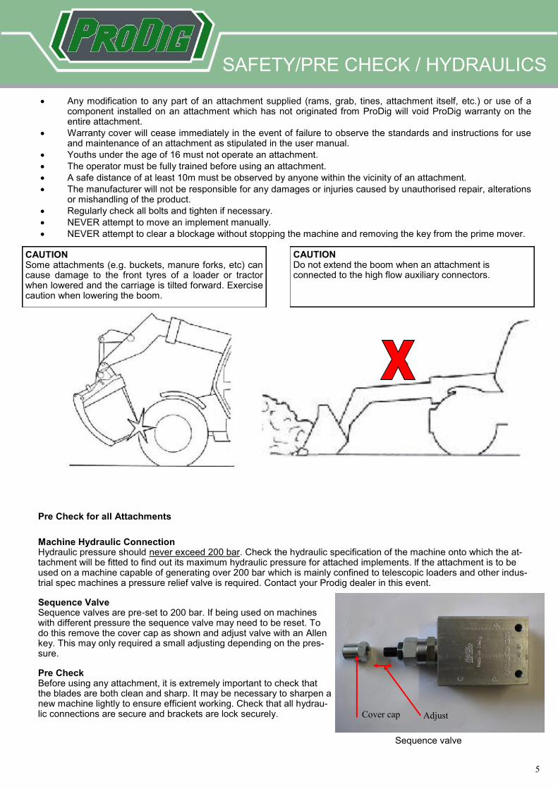
CAUTION Some attachments (e.g. buckets, manure forks, etc) can cause damage to the front tyres of a loader or tractor when lowered and the carriage is tilted forward. Exercise caution when lowering the boom.
CAUTION Do not extend the boom when an attachment is connected to the high flow auxiliary connectors.
SAFETY/PRE CHECK / HYDRAULICS
Pre Check for all Attachments
Machine Hydraulic Connection Hydraulic pressure should never exceed 200 bar. Check the hydraulic specification of the machine onto which the at-tachment will be fitted to find out its maximum hydraulic pressure for attached implements. lf the attachment is to be used on a machine capable of generating over 200 bar which is mainly confined to telescopic loaders and other indus-trial spec machines a pressure relief valve is required. Contact your Prodig dealer in this event.
Sequence Valve Sequence valves are pre-set to 200 bar. If being used on machines with different pressure the sequence valve may need to be reset. To do this remove the cover cap as shown and adjust valve with an Allen key. This may only required a small adjusting depending on the pres-sure.
Pre Check Before using any attachment, it is extremely important to check that the blades are both clean and sharp. It may be necessary to sharpen a new machine lightly to ensure efficient working. Check that all hydrau-lic connections are secure and brackets are lock securely.
Cover cap Adjust
Sequence valve

6
6
Description of safety warnings
It is It is important that all safety warnings and instructions are understood and followed. If any of the decals
become damaged, or are missing, they are available from Prodig Attachments.
Part number: ST 05 Warning! Keep animals away from the blades. Always leave the grabs in the closed position when it is not in use with blades covered.
Part number: ST 04 Continuously check the condition of the blades. Sharpen to keep the attach-ment in optimum cutting condition. Blades should only be sharpened with a file.
Part number: ST 06 Read user manual before use. Hydraulic pressure should never exceed 200 bar. See hydraulic section for further details (page 5). User manual downloadable from WWW.PRODIGATTACHMENTS.COM
Part number: ST 07 Grease daily to keep the attachment in optimum condition.
Part number: ST 03 NOTICE. Blades to be sharpened before first use and weekly thereafter
Part number: ST 08 Warning. Pinch point. Keep hands clear during operation.
Part number: ST 09 Name plate/ identification. Always quote the serial number when obtaining replacement parts 1. Serial number 2. Profile 3. Machine/ hitch 4. Tooth system 5. Capacity (ISO rates m3) 6. Weight (kg) 7. Width (mm) 8. Year of manufacture
SAFETY LABELS
7
7
HITCHING / UNHITCHING
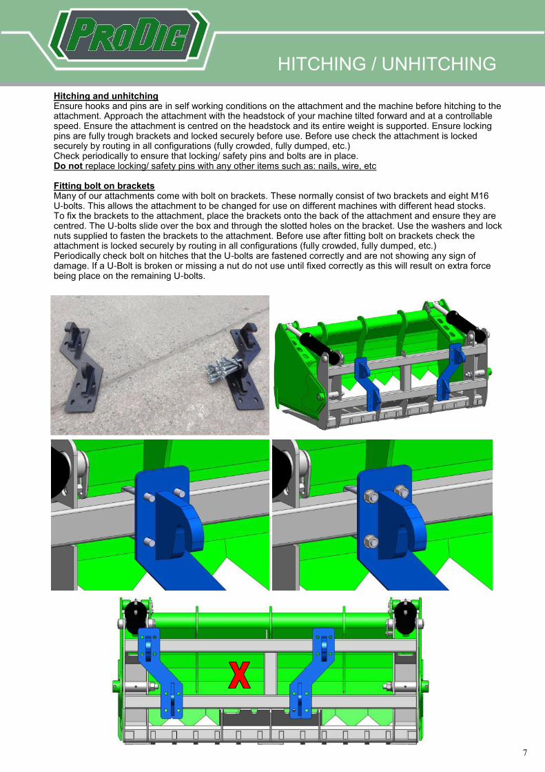
Hitching and unhitching Ensure hooks and pins are in self working conditions on the attachment and the machine before hitching to the attachment. Approach the attachment with the headstock of your machine tilted forward and at a controllable speed. Ensure the attachment is centred on the headstock and its entire weight is supported. Ensure locking pins are fully trough brackets and locked securely before use. Before use check the attachment is locked securely by routing in all configurations (fully crowded, fully dumped, etc.) Check periodically to ensure that locking/ safety pins and bolts are in place. Do not replace locking/ safety pins with any other items such as: nails, wire, etc Fitting bolt on brackets Many of our attachments come with bolt on brackets. These normally consist of two brackets and eight M16 U-bolts. This allows the attachment to be changed for use on different machines with different head stocks. To fix the brackets to the attachment, place the brackets onto the back of the attachment and ensure they are centred. The U-bolts slide over the box and through the slotted holes on the bracket. Use the washers and lock nuts supplied to fasten the brackets to the attachment. Before use after fitting bolt on brackets check the attachment is locked securely by routing in all configurations (fully crowded, fully dumped, etc.) Periodically check bolt on hitches that the U-bolts are fastened correctly and are not showing any sign of damage. If a U-Bolt is broken or missing a nut do not use until fixed correctly as this will result on extra force being place on the remaining U-bolts.
8
8
SHARPENING BLADES
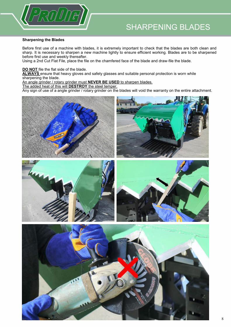
Sharpening the Blades Before first use of a machine with blades, it is extremely important to check that the blades are both clean and sharp. It is necessary to sharpen a new machine lightly to ensure efficient working. Blades are to be sharpened before first use and weekly thereafter. Using a 2nd Cut Flat File, place the file on the chamfered face of the blade and draw-file the blade. DO NOT file the flat side of the blade. ALWAYS ensure that heavy gloves and safety glasses and suitable personal protection is worn while sharpening the blade. An angle grinder / rotary grinder must NEVER BE USED to sharpen blades. The added heat of this will DESTROY the steel temper. Any sign of use of a angle grinder / rotary grinder on the blades will void the warranty on the entire attachment.
9
9
SHEAR GENIUS
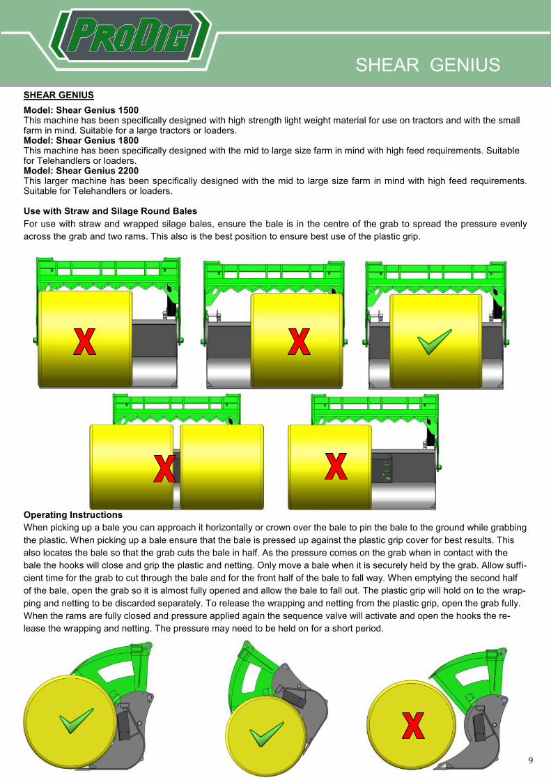
Model: Shear Genius 1500 This machine has been specifically designed with high strength light weight material for use on tractors and with the small farm in mind. Suitable for a large tractors or loaders. Model: Shear Genius 1800 This machine has been specifically designed with the mid to large size farm in mind with high feed requirements. Suitable for Telehandlers or loaders. Model: Shear Genius 2200 This larger machine has been specifically designed with the mid to large size farm in mind with high feed requirements. Suitable for Telehandlers or loaders. Use with Straw and Silage Round Bales
For use with straw and wrapped silage bales, ensure the bale is in the centre of the grab to spread the pressure evenly
across the grab and two rams. This also is the best position to ensure best use of the plastic grip.
Operating Instructions
When picking up a bale you can approach it horizontally or crown over the bale to pin the bale to the ground while grabbing
the plastic. When picking up a bale ensure that the bale is pressed up against the plastic grip cover for best results. This
also locates the bale so that the grab cuts the bale in half. As the pressure comes on the grab when in contact with the
bale the hooks will close and grip the plastic and netting. Only move a bale when it is securely held by the grab. Allow suffi-
cient time for the grab to cut through the bale and for the front half of the bale to fall way. When emptying the second half
of the bale, open the grab so it is almost fully opened and allow the bale to fall out. The plastic grip will hold on to the wrap-
ping and netting to be discarded separately. To release the wrapping and netting from the plastic grip, open the grab fully.
When the rams are fully closed and pressure applied again the sequence valve will activate and open the hooks the re-
lease the wrapping and netting. The pressure may need to be held on for a short period.
SHEAR GENIUS
10
10
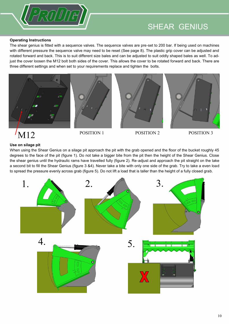
Operating Instructions
The shear genius is fitted with a sequence valves. The sequence valves are pre-set to 200 bar. If being used on machines
with different pressure the sequence valve may need to be reset (See page 8). The plastic grip cover can be adjusted and
rotated forward and back. This is to suit different size bales and can be adjusted to suit oddly shaped bales as well. To ad-
just the cover loosen the M12 bolt both sides of the cover. This allows the cover to be rotated forward and back. There are
three different settings and when set to your requirements replace and tighten the bolts.
M12 POSITION 1 POSITION 2 POSITION 3
Use on silage pit
When using the Shear Genius on a silage pit approach the pit with the grab opened and the floor of the bucket roughly 45
degrees to the face of the pit (figure 1). Do not take a bigger bite from the pit then the height of the Shear Genius. Close
the shear genius until the hydraulic rams have travelled fully (figure 2). Re-adjust and approach the pit straight on the take
a second bit to fill the Shear Genius (figure 3 &4). Never take a bite with only one side of the grab. Try to take a even load
to spread the pressure evenly across grab (figure 5). Do not lift a load that is taller than the height of a fully closed grab.
1. 2. 3.
4. 5.
SHEAR GENIUS
11
11
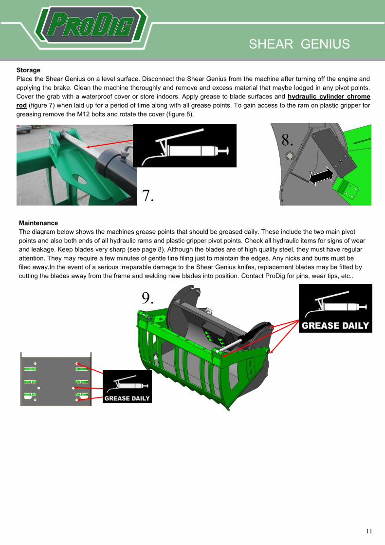
Storage
Place the Shear Genius on a level surface. Disconnect the Shear Genius from the machine after turning off the engine and
applying the brake. Clean the machine thoroughly and remove and excess material that maybe lodged in any pivot points.
Cover the grab with a waterproof cover or store indoors. Apply grease to blade surfaces and hydraulic cylinder chrome
rod (figure 7) when laid up for a period of time along with all grease points. To gain access to the ram on plastic gripper for
greasing remove the M12 bolts and rotate the cover (figure 8).
7.
8.
Maintenance
The diagram below shows the machines grease points that should be greased daily. These include the two main pivot
points and also both ends of all hydraulic rams and plastic gripper pivot points. Check all hydraulic items for signs of wear
and leakage. Keep blades very sharp (see page 8). Although the blades are of high quality steel, they must have regular
attention. They may require a few minutes of gentle fine filing just to maintain the edges. Any nicks and burrs must be
filed away.In the event of a serious irreparable damage to the Shear Genius knifes, replacement blades may be fitted by
cutting the blades away from the frame and welding new blades into position. Contact ProDig for pins, wear tips, etc..
SHEAR GENIUS
9.

12
12
MEGA BITE Model: Mega Bite 1500 This machine has been specifically designed with high strength light weight material for use on tractors and with the small farm in mind. Suitable for a large tractors or loaders. Model: Mega Bite 1800 This machine has been specifically designed with the mid to large size farm in mind with high feed requirements. Suitable for telescopic handler or loader. Model: Mega Bite 2200 & Mega Bite 2500 This larger machine has been specifically designed with the mid to large size farm in mind with high feed requirements. Suitable for large telescopic handler or loader.
MEGA BITE
Operating Instructions The mega bite is fitted with a sequence valves. The sequence valves are pre-set to 200 bar. If being used on machines with different pressure the sequence valve may need to be reset (See page 5). The plastic grip cover can be adjusted forward and back. This is to suit different size bales and can be adjusted to suit oddly shaped bales as well. To adjust the cover loosen the two M12 bolts on top of the cover This allows the cover to be lifted and brought forward and back. There are three different settings and when set to your requirements replace and tighten the bolts. When being use on a pit place box in position 1.
POSITION 1 POSITION 2 POSITION 3 M12 BOLTS When picking up a bale you can approach it horizontally or crown over the bale to pin the bale to the ground while grabbing
the plastic. When picking up a bale ensure that the bale is pressed up against the plastic grip cover for best results. This
also locates the bale so that the grab cuts the bale in half. As the pressure comes on the grab when in contact with the
bale the hooks will close and grip the plastic and netting. Only move a bale when it is securely held by the grab. Allow suffi-
cient time for the grab to cut through the bale and for the front half of the bale to fall way. When emptying the second half
of the bale, open the grab so it is almost fully opened and allow the bale to fall out. The plastic grip will hold on to the wrap-
ping and netting to be discarded separately. To release the wrapping and netting from the plastic grip, open the grab fully.
When the rams are fully closed and pressure applied again the sequence valve will activate and open the hooks the re-
lease the wrapping and netting. The pressure may need to be held on for a short period.
See shear grad section (page 14) for using Mega Bite on a pit.
13
13
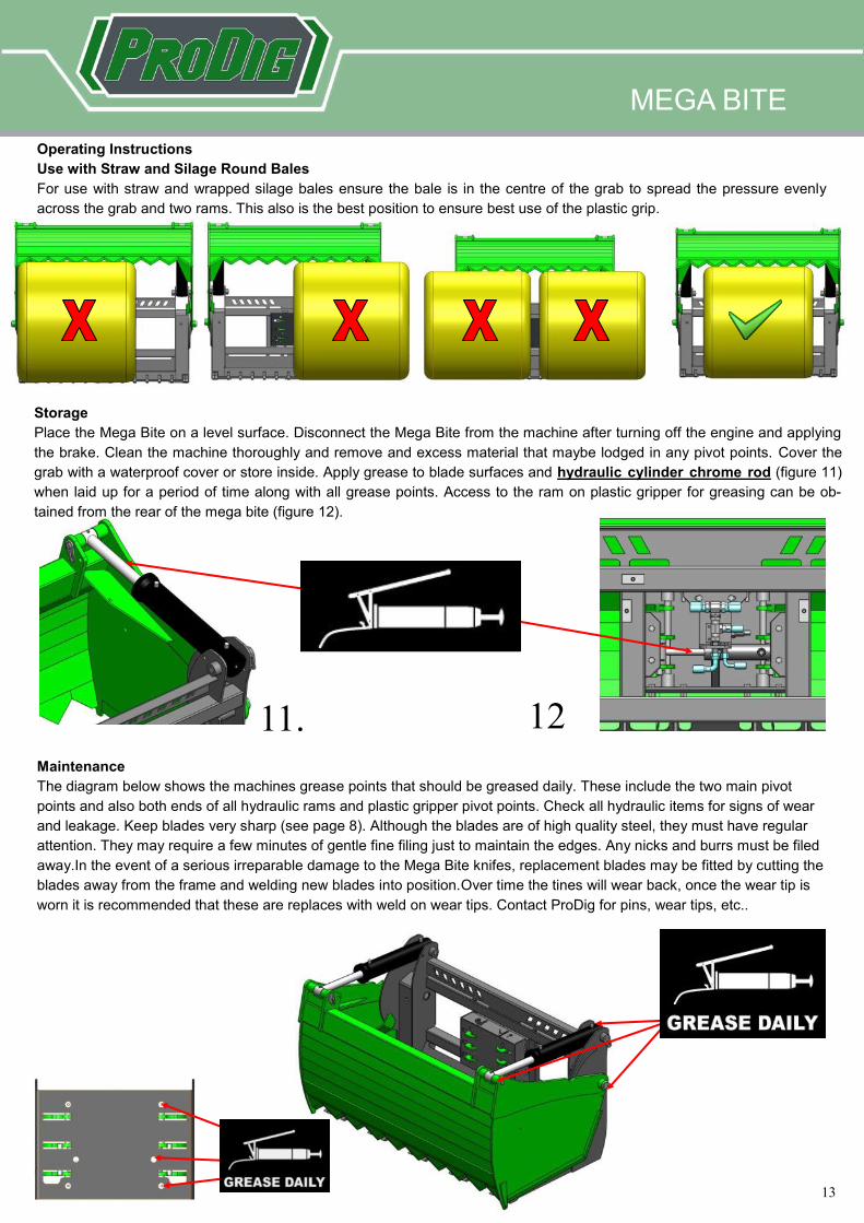
Operating Instructions
Use with Straw and Silage Round Bales
For use with straw and wrapped silage bales ensure the bale is in the centre of the grab to spread the pressure evenly
across the grab and two rams. This also is the best position to ensure best use of the plastic grip.
11. 12
Storage
Place the Mega Bite on a level surface. Disconnect the Mega Bite from the machine after turning off the engine and applying
the brake. Clean the machine thoroughly and remove and excess material that maybe lodged in any pivot points. Cover the
grab with a waterproof cover or store inside. Apply grease to blade surfaces and hydraulic cylinder chrome rod (figure 11)
when laid up for a period of time along with all grease points. Access to the ram on plastic gripper for greasing can be ob-
tained from the rear of the mega bite (figure 12).
Maintenance
The diagram below shows the machines grease points that should be greased daily. These include the two main pivot
points and also both ends of all hydraulic rams and plastic gripper pivot points. Check all hydraulic items for signs of wear
and leakage. Keep blades very sharp (see page 8). Although the blades are of high quality steel, they must have regular
attention. They may require a few minutes of gentle fine filing just to maintain the edges. Any nicks and burrs must be filed
away.In the event of a serious irreparable damage to the Mega Bite knifes, replacement blades may be fitted by cutting the
blades away from the frame and welding new blades into position.Over time the tines will wear back, once the wear tip is
worn it is recommended that these are replaces with weld on wear tips. Contact ProDig for pins, wear tips, etc..
MEGA BITE
14
14
SHEAR GRAB
Storage
Place the Shear Grab on a level surface. Disconnect the grab from the tractor after turning off the engine and applying the
brake. Clean the machine thoroughly and remove and excess material that maybe lodged in any pivot points. Apply grease
to the proportion of the ram that is showing. Cover the grab with a waterproof cover or store indoors.
Maintenance
The diagram below shows the machines grease points that should be greased daily. These include the two main pivot
points and also both ends of all hydraulic rams. Check all hydraulic items for signs of wear and leakage. Keep blades very
sharp (see page 8). Although the blades are of high quality steel, they must have regular attention. They may require a few
minutes of gentle fine filing just to maintain the edges. Any nicks and burrs must be filed away. In the event of a serious
irreparable damage to the Shear Grab knifes, replacement blades may be fitted by cutting the blades away from the frame
and welding new blades into position. Over time the tines will wear back, once the wear tip is worn it is recommended that
these are replaces with weld on wear tips. Contact ProDig for replacement pins, blades, wear tips, etc..
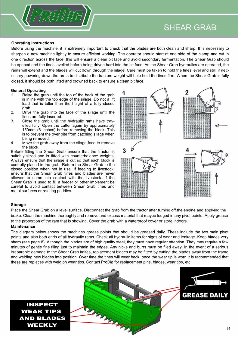
General Operating 1. Raise the grab until the top of the back of the grab
is inline with the top edge of the silage. Do not a lift load that is taller than the height of a fully closed grab.
2. Drive the grab into the face of the silage until the tines are fully inserted.
3. Close the grab until the hydraulic rams have trav-elled fully. Open the cutter again by approximately 150mm (6 Inches) before removing the block. This is to prevent the over bite from catching silage when being removed.
4. Move the grab away from the silage face to remove the block.
Before fitting the Shear Grab ensure that the tractor is suitably sized and is fitted with counterbalance weights. Always ensure that the silage is cut so that each block is centrally placed in the grab. Return the Shear Grab to the closed position when not in use. If feeding to livestock, ensure that the Shear Grab tines and blades are never allowed to come into contact with the livestock. If the Shear Grab is used to fill a feeder or other implement be careful to avoid contact between Shear Grab tines and metal surfaces or rotating paddles.
Operating Instructions
Before using the machine, it is extremely important to check that the blades are both clean and sharp. It is necessary to
sharpen a new machine lightly to ensure efficient working. The operator should start at one side of the clamp and cut in
one direction across the face, this will ensure a clean pit face and avoid secondary fermentation. The Shear Grab should
be opened and the tines levelled before being driven hard into the pit face. As the Shear Grab hydraulics are operated, the
rams will extend and the blades will cut down through the silage. Care must be taken to hold the tines level and still, if nec-
essary powering down the arms to distribute the tractors weight will help hold the tines firm. When the Shear Grab is fully
closed, it should be both lifted and crowned back to ensure a clean pit face.
15
15
TRACTOR TINE GRAB
TRACTOR TINE GRAB & TELEHANDLER TINE GRAB
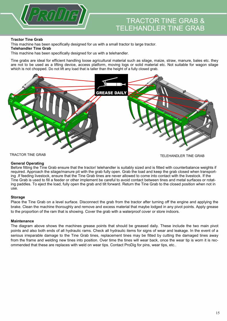
Tractor Tine Grab
This machine has been specifically designed for us with a small tractor to large tractor. Telehandler Tine Grab
This machine has been specifically designed for us with a telehandler.
TELEHANDLER TINE GRAB
General Operating Before fitting the Tine Grab ensure that the tractor/ telehandler is suitably sized and is fitted with counterbalance weights if required. Approach the silage/manure pit with the grab fully open. Grab the load and keep the grab closed when transport-ing .If feeding livestock, ensure that the Tine Grab tines are never allowed to come into contact with the livestock. If the Tine Grab is used to fill a feeder or other implement be careful to avoid contact between tines and metal surfaces or rotat-ing paddles. To eject the load, fully open the grab and tilt forward. Return the Tine Grab to the closed position when not in use.
Storage
Place the Tine Grab on a level surface. Disconnect the grab from the tractor after turning off the engine and applying the
brake. Clean the machine thoroughly and remove and excess material that maybe lodged in any pivot points. Apply grease
to the proportion of the ram that is showing. Cover the grab with a waterproof cover or store indoors.
Maintenance
The diagram above shows the machines grease points that should be greased daily. These include the two main pivot
points and also both ends of all hydraulic rams. Check all hydraulic items for signs of wear and leakage. In the event of a
serious irreparable damage to the Tine Grab tines, replacement tines may be fitted by cutting the damaged tines away
from the frame and welding new tines into position. Over time the tines will wear back, once the wear tip is worn it is rec-
ommended that these are replaces with weld on wear tips. Contact ProDig for pins, wear tips, etc..
Tine grabs are ideal for efficient handling loose agricultural material such as silage, maize, straw, manure, bales etc. they are not to be used as a lifting device, access platform, moving logs or solid material etc. Not suitable for wagon silage which is not chopped. Do not lift any load that is taller than the height of a fully closed grab.
16
16
TRACTOR GRAPPLE BUCKET
TRACTOR GRAPPLE BUCKET & TELEHANDLER GRAPPLE BUCKET
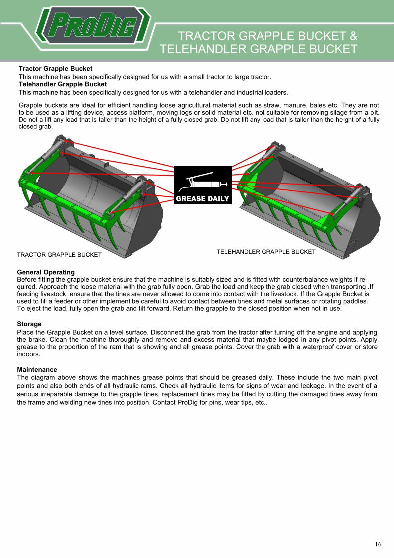
Tractor Grapple Bucket
This machine has been specifically designed for us with a small tractor to large tractor. Telehandler Grapple Bucket
This machine has been specifically designed for us with a telehandler and industrial loaders.
TELEHANDLER GRAPPLE BUCKET
General Operating Before fitting the grapple bucket ensure that the machine is suitably sized and is fitted with counterbalance weights if re-quired. Approach the loose material with the grab fully open. Grab the load and keep the grab closed when transporting .If feeding livestock, ensure that the tines are never allowed to come into contact with the livestock. If the Grapple Bucket is used to fill a feeder or other implement be careful to avoid contact between tines and metal surfaces or rotating paddles. To eject the load, fully open the grab and tilt forward. Return the grapple to the closed position when not in use.
Storage
Place the Grapple Bucket on a level surface. Disconnect the grab from the tractor after turning off the engine and applying the brake. Clean the machine thoroughly and remove and excess material that maybe lodged in any pivot points. Apply grease to the proportion of the ram that is showing and all grease points. Cover the grab with a waterproof cover or store indoors.
Maintenance
The diagram above shows the machines grease points that should be greased daily. These include the two main pivot
points and also both ends of all hydraulic rams. Check all hydraulic items for signs of wear and leakage. In the event of a
serious irreparable damage to the grapple tines, replacement tines may be fitted by cutting the damaged tines away from
the frame and welding new tines into position. Contact ProDig for pins, wear tips, etc..
Grapple buckets are ideal for efficient handling loose agricultural material such as straw, manure, bales etc. They are not to be used as a lifting device, access platform, moving logs or solid material etc. not suitable for removing silage from a pit. Do not a lift any load that is taller than the height of a fully closed grab. Do not lift any load that is taller than the height of a fully closed grab.
17
17
BAG FILLER BUCKET
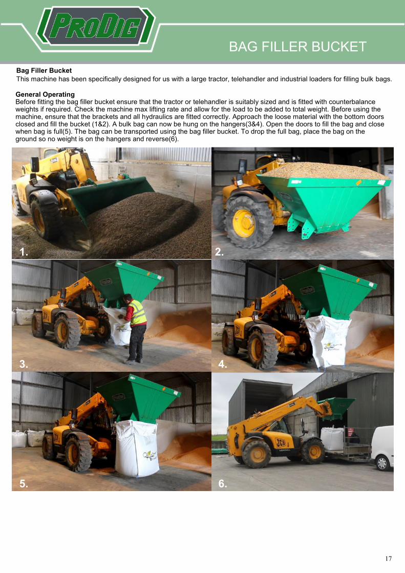
General Operating Before fitting the bag filler bucket ensure that the tractor or telehandler is suitably sized and is fitted with counterbalance weights if required. Check the machine max lifting rate and allow for the load to be added to total weight. Before using the machine, ensure that the brackets and all hydraulics are fitted correctly. Approach the loose material with the bottom doors closed and fill the bucket (1&2). A bulk bag can now be hung on the hangers(3&4). Open the doors to fill the bag and close when bag is full(5). The bag can be transported using the bag filler bucket. To drop the full bag, place the bag on the ground so no weight is on the hangers and reverse(6).
Bag Filler Bucket
This machine has been specifically designed for us with a large tractor, telehandler and industrial loaders for filling bulk bags.
1. 2.
3. 4.
5. 6.
18
18
BAG FILLER BUCKET
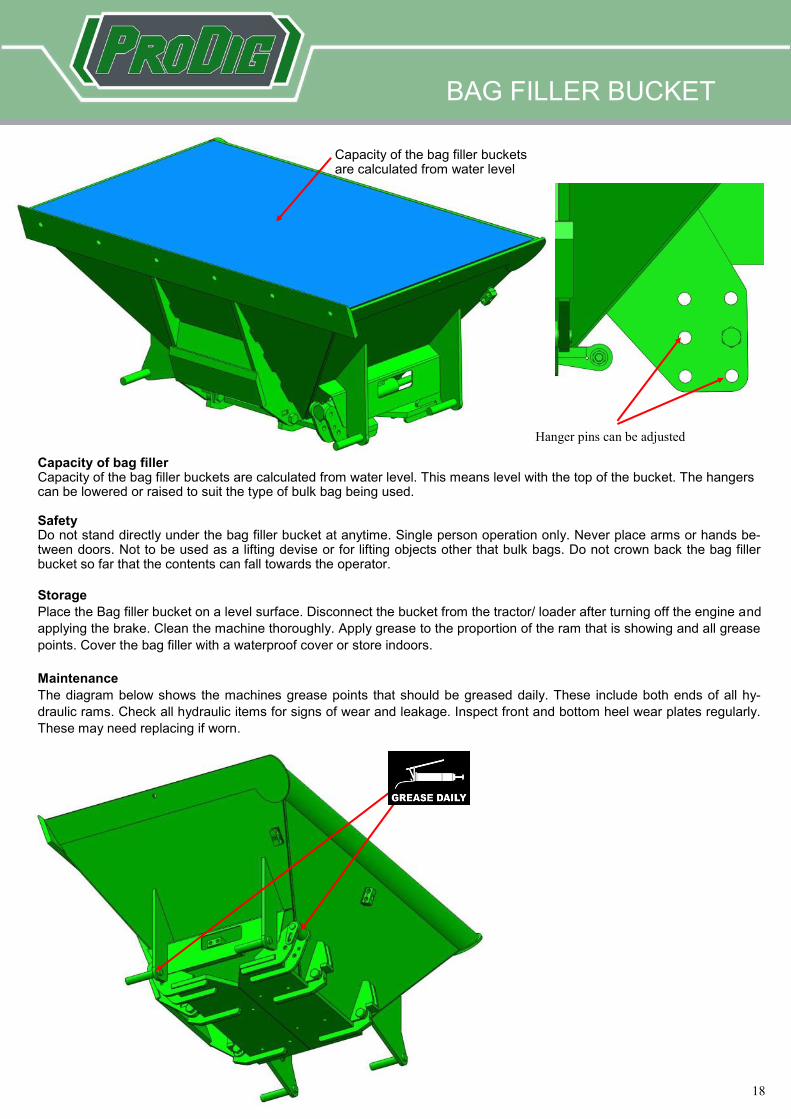
Capacity of bag filler Capacity of the bag filler buckets are calculated from water level. This means level with the top of the bucket. The hangers can be lowered or raised to suit the type of bulk bag being used. Safety Do not stand directly under the bag filler bucket at anytime. Single person operation only. Never place arms or hands be-tween doors. Not to be used as a lifting devise or for lifting objects other that bulk bags. Do not crown back the bag filler bucket so far that the contents can fall towards the operator.
Storage
Place the Bag filler bucket on a level surface. Disconnect the bucket from the tractor/ loader after turning off the engine and
applying the brake. Clean the machine thoroughly. Apply grease to the proportion of the ram that is showing and all grease
points. Cover the bag filler with a waterproof cover or store indoors.
Maintenance
The diagram below shows the machines grease points that should be greased daily. These include both ends of all hy-
draulic rams. Check all hydraulic items for signs of wear and leakage. Inspect front and bottom heel wear plates regularly.
These may need replacing if worn.
Hanger pins can be adjusted
Capacity of the bag filler buckets are calculated from water level
19
19
BAG FILLER BUCKET / ROUND NECK
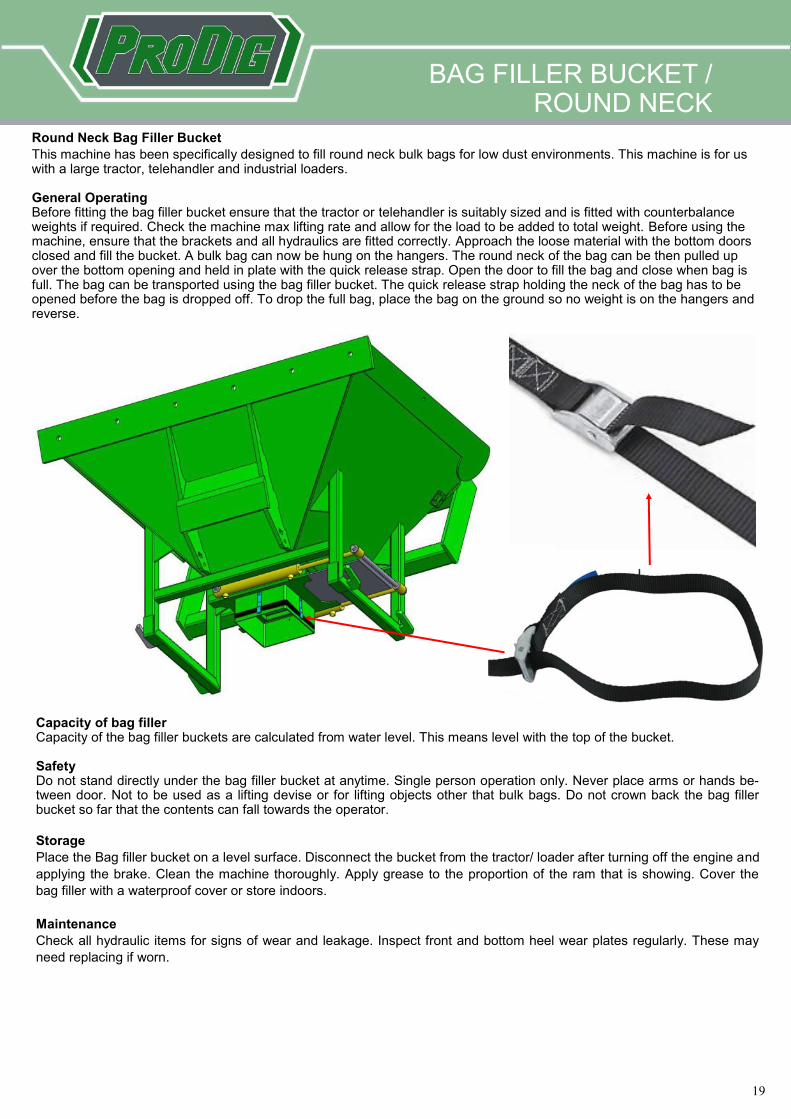
Round Neck Bag Filler Bucket
This machine has been specifically designed to fill round neck bulk bags for low dust environments. This machine is for us with a large tractor, telehandler and industrial loaders. General Operating Before fitting the bag filler bucket ensure that the tractor or telehandler is suitably sized and is fitted with counterbalance weights if required. Check the machine max lifting rate and allow for the load to be added to total weight. Before using the machine, ensure that the brackets and all hydraulics are fitted correctly. Approach the loose material with the bottom doors closed and fill the bucket. A bulk bag can now be hung on the hangers. The round neck of the bag can be then pulled up over the bottom opening and held in plate with the quick release strap. Open the door to fill the bag and close when bag is full. The bag can be transported using the bag filler bucket. The quick release strap holding the neck of the bag has to be opened before the bag is dropped off. To drop the full bag, place the bag on the ground so no weight is on the hangers and reverse.
Capacity of bag filler Capacity of the bag filler buckets are calculated from water level. This means level with the top of the bucket. Safety Do not stand directly under the bag filler bucket at anytime. Single person operation only. Never place arms or hands be-tween door. Not to be used as a lifting devise or for lifting objects other that bulk bags. Do not crown back the bag filler bucket so far that the contents can fall towards the operator.
Storage
Place the Bag filler bucket on a level surface. Disconnect the bucket from the tractor/ loader after turning off the engine and
applying the brake. Clean the machine thoroughly. Apply grease to the proportion of the ram that is showing. Cover the
bag filler with a waterproof cover or store indoors.
Maintenance
Check all hydraulic items for signs of wear and leakage. Inspect front and bottom heel wear plates regularly. These may
need replacing if worn.
20
20
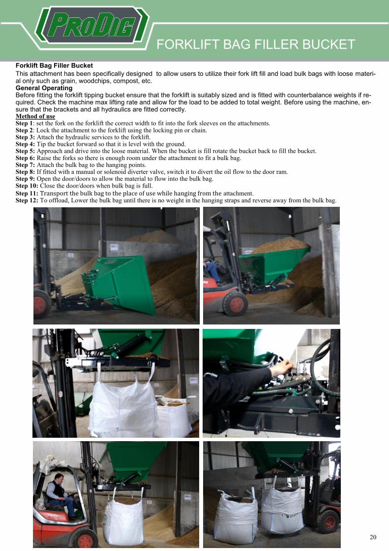
Forklift Bag Filler Bucket
This attachment has been specifically designed to allow users to utilize their fork lift fill and load bulk bags with loose materi-al only such as grain, woodchips, compost, etc. General Operating Before fitting the forklift tipping bucket ensure that the forklift is suitably sized and is fitted with counterbalance weights if re-quired. Check the machine max lifting rate and allow for the load to be added to total weight. Before using the machine, en-sure that the brackets and all hydraulics are fitted correctly. Method of use Step 1: set the fork on the forklift the correct width to fit into the fork sleeves on the attachments. Step 2: Lock the attachment to the forklift using the locking pin or chain. Step 3: Attach the hydraulic services to the forklift. Step 4: Tip the bucket forward so that it is level with the ground. Step 5: Approach and drive into the loose material. When the bucket is fill rotate the bucket back to fill the bucket. Step 6: Raise the forks so there is enough room under the attachment to fit a bulk bag. Step 7: Attach the bulk bag to the hanging points. Step 8: If fitted with a manual or solenoid diverter valve, switch it to divert the oil flow to the door ram. Step 9: Open the door/doors to allow the material to flow into the bulk bag. Step 10: Close the door/doors when bulk bag is full.
Step 11: Transport the bulk bag to the place of use while hanging from the attachment. Step 12: To offload, Lower the bulk bag until there is no weight in the hanging straps and reverse away from the bulk bag.
FORKLIFT BAG FILLER BUCKET
21
21
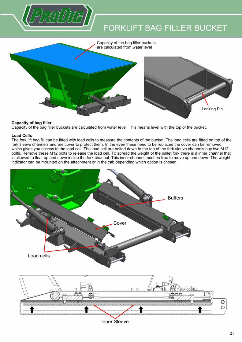
Capacity of bag filler Capacity of the bag filler buckets are calculated from water level. This means level with the top of the bucket.
Capacity of the bag filler buckets are calculated from water level
Locking Pin
Load Cells The fork lift bag fill can be fitted with load cells to measure the contents of the bucket. The load cells are fitted on top of the fork sleeve channels and are cover to protect them. In the even these need to be replaced the cover can be removed which gives you access to the load cell. The load cell are bolted down to the top of the fork sleeve channels buy two M12 bolts. Remove these M12 bolts to release the load cell. To spread the weight of the pallet fork there is a inner channel that is allowed to float up and down inside the fork channel. This inner channel must be free to move up and down. The weight indicator can be mounted on the attachment or in the cab depending which option is chosen.
Cover
Load cells
Buffers
Inner Sleeve
FORKLIFT BAG FILLER BUCKET
22
22
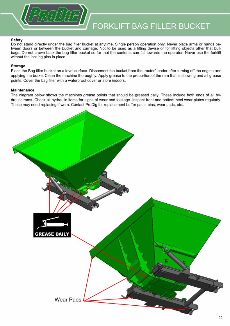
Safety Do not stand directly under the bag filler bucket at anytime. Single person operation only. Never place arms or hands be-tween doors or between the bucket and carriage. Not to be used as a lifting devise or for lifting objects other that bulk bags. Do not crown back the bag filler bucket so far that the contents can fall towards the operator. Never use the forklift without the locking pins in place
Storage
Place the Bag filler bucket on a level surface. Disconnect the bucket from the tractor/ loader after turning off the engine and
applying the brake. Clean the machine thoroughly. Apply grease to the proportion of the ram that is showing and all grease
points. Cover the bag filler with a waterproof cover or store indoors.
Maintenance
The diagram below shows the machines grease points that should be greased daily. These include both ends of all hy-
draulic rams. Check all hydraulic items for signs of wear and leakage. Inspect front and bottom heel wear plates regularly.
These may need replacing if worn. Contact ProDig for replacement buffer pads, pins, wear pads, etc..
FORKLIFT BAG FILLER BUCKET
Wear Pads
23
23
FORKLIFT TIPPING BUCKET
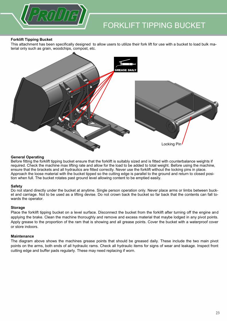
Forklift Tipping Bucket
This attachment has been specifically designed to allow users to utilize their fork lift for use with a bucket to load bulk ma-terial only such as grain, woodchips, compost, etc.
General Operating Before fitting the forklift tipping bucket ensure that the forklift is suitably sized and is fitted with counterbalance weights if required. Check the machine max lifting rate and allow for the load to be added to total weight. Before using the machine, ensure that the brackets and all hydraulics are fitted correctly. Never use the forklift without the locking pins in place. Approach the loose material with the bucket tipped so the cutting edge is parallel to the ground and return to closed posi-tion when full. The bucket rotates past ground level allowing content to be emptied easily. Safety Do not stand directly under the bucket at anytime. Single person operation only. Never place arms or limbs between buck-et and carriage. Not to be used as a lifting devise. Do not crown back the bucket so far back that the contents can fall to-wards the operator.
Storage
Place the forklift tipping bucket on a level surface. Disconnect the bucket from the forklift after turning off the engine and
applying the brake. Clean the machine thoroughly and remove and excess material that maybe lodged in any pivot points.
Apply grease to the proportion of the ram that is showing and all grease points. Cover the bucket with a waterproof cover
or store indoors.
Maintenance
The diagram above shows the machines grease points that should be greased daily. These include the two main pivot
points on the arms, both ends of all hydraulic rams. Check all hydraulic items for signs of wear and leakage. Inspect front
cutting edge and buffer pads regularly. These may need replacing if worn.
Locking Pin
24
24
HI-TIP BUCKET
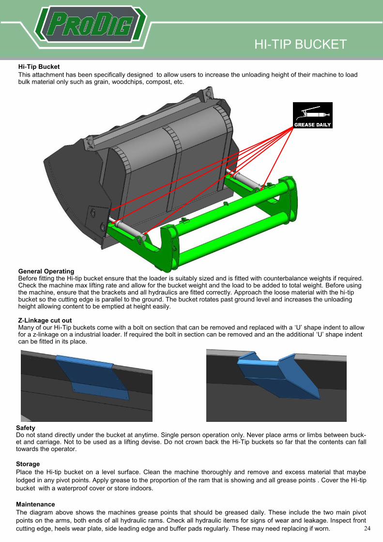
Hi-Tip Bucket
This attachment has been specifically designed to allow users to increase the unloading height of their machine to load bulk material only such as grain, woodchips, compost, etc.
General Operating Before fitting the Hi-tip bucket ensure that the loader is suitably sized and is fitted with counterbalance weights if required. Check the machine max lifting rate and allow for the bucket weight and the load to be added to total weight. Before using the machine, ensure that the brackets and all hydraulics are fitted correctly. Approach the loose material with the hi-tip bucket so the cutting edge is parallel to the ground. The bucket rotates past ground level and increases the unloading height allowing content to be emptied at height easily. Z-Linkage cut out Many of our Hi-Tip buckets come with a bolt on section that can be removed and replaced with a ‘U’ shape indent to allow for a z-linkage on a industrial loader. If required the bolt in section can be removed and an the additional ‘U’ shape indent can be fitted in its place.
Safety Do not stand directly under the bucket at anytime. Single person operation only. Never place arms or limbs between buck-et and carriage. Not to be used as a lifting devise. Do not crown back the Hi-Tip buckets so far that the contents can fall towards the operator.
Storage
Place the Hi-tip bucket on a level surface. Clean the machine thoroughly and remove and excess material that maybe
lodged in any pivot points. Apply grease to the proportion of the ram that is showing and all grease points . Cover the Hi-tip
bucket with a waterproof cover or store indoors.
Maintenance
The diagram above shows the machines grease points that should be greased daily. These include the two main pivot
points on the arms, both ends of all hydraulic rams. Check all hydraulic items for signs of wear and leakage. Inspect front
cutting edge, heels wear plate, side leading edge and buffer pads regularly. These may need replacing if worn.
25
25
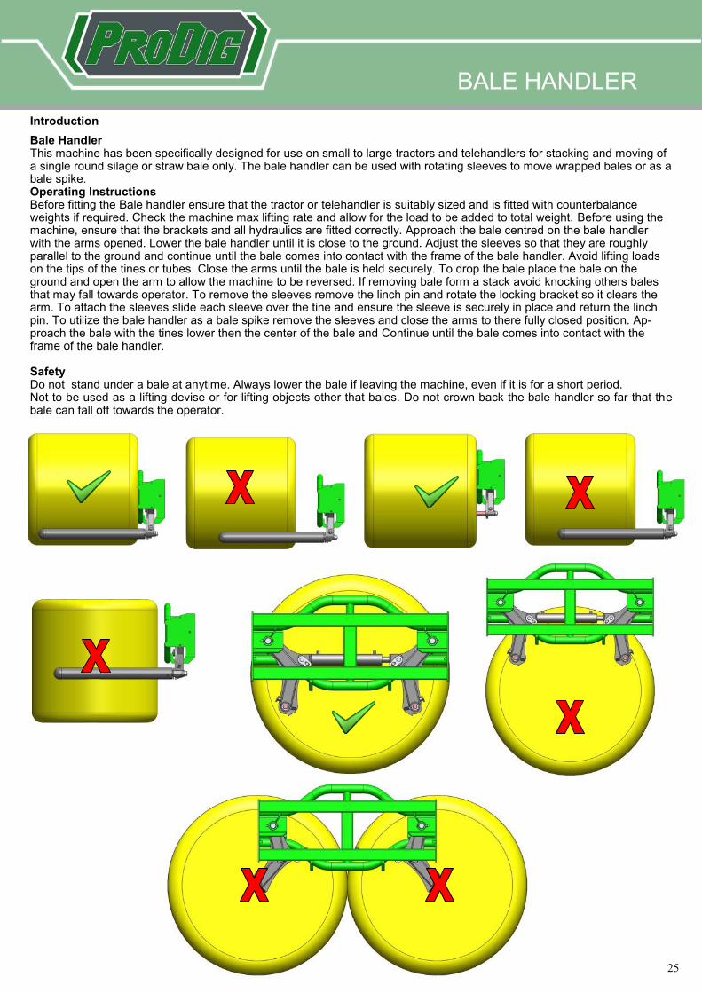
Introduction
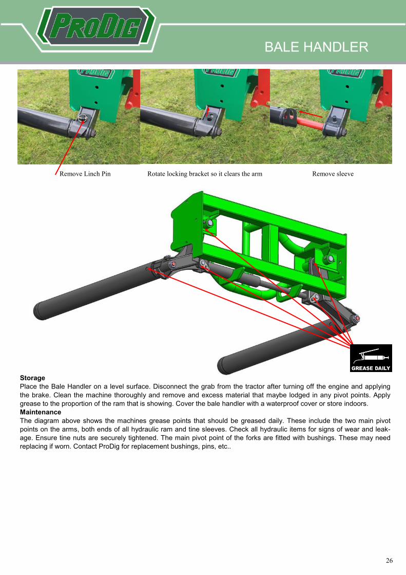
Bale Handler This machine has been specifically designed for use on small to large tractors and telehandlers for stacking and moving of a single round silage or straw bale only. The bale handler can be used with rotating sleeves to move wrapped bales or as a bale spike. Operating Instructions Before fitting the Bale handler ensure that the tractor or telehandler is suitably sized and is fitted with counterbalance weights if required. Check the machine max lifting rate and allow for the load to be added to total weight. Before using the machine, ensure that the brackets and all hydraulics are fitted correctly. Approach the bale centred on the bale handler with the arms opened. Lower the bale handler until it is close to the ground. Adjust the sleeves so that they are roughly parallel to the ground and continue until the bale comes into contact with the frame of the bale handler. Avoid lifting loads on the tips of the tines or tubes. Close the arms until the bale is held securely. To drop the bale place the bale on the ground and open the arm to allow the machine to be reversed. If removing bale form a stack avoid knocking others bales that may fall towards operator. To remove the sleeves remove the linch pin and rotate the locking bracket so it clears the arm. To attach the sleeves slide each sleeve over the tine and ensure the sleeve is securely in place and return the linch pin. To utilize the bale handler as a bale spike remove the sleeves and close the arms to there fully closed position. Ap-proach the bale with the tines lower then the center of the bale and Continue until the bale comes into contact with the frame of the bale handler. Safety Do not stand under a bale at anytime. Always lower the bale if leaving the machine, even if it is for a short period. Not to be used as a lifting devise or for lifting objects other that bales. Do not crown back the bale handler so far that the bale can fall off towards the operator.
BALE HANDLER
26
26
Storage
Place the Bale Handler on a level surface. Disconnect the grab from the tractor after turning off the engine and applying
the brake. Clean the machine thoroughly and remove and excess material that maybe lodged in any pivot points. Apply
grease to the proportion of the ram that is showing. Cover the bale handler with a waterproof cover or store indoors.
Maintenance
The diagram above shows the machines grease points that should be greased daily. These include the two main pivot
points on the arms, both ends of all hydraulic ram and tine sleeves. Check all hydraulic items for signs of wear and leak-
age. Ensure tine nuts are securely tightened. The main pivot point of the forks are fitted with bushings. These may need
replacing if worn. Contact ProDig for replacement bushings, pins, etc..
Rotate locking bracket so it clears the arm Remove Linch Pin Remove sleeve
BALE HANDLER
27
27
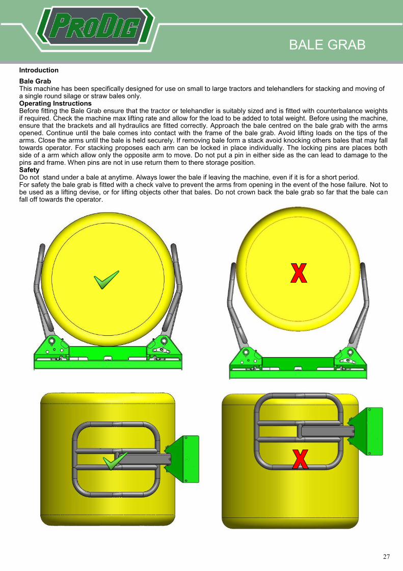
Introduction
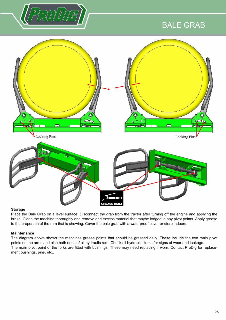
Bale Grab This machine has been specifically designed for use on small to large tractors and telehandlers for stacking and moving of a single round silage or straw bales only. Operating Instructions Before fitting the Bale Grab ensure that the tractor or telehandler is suitably sized and is fitted with counterbalance weights if required. Check the machine max lifting rate and allow for the load to be added to total weight. Before using the machine, ensure that the brackets and all hydraulics are fitted correctly. Approach the bale centred on the bale grab with the arms opened. Continue until the bale comes into contact with the frame of the bale grab. Avoid lifting loads on the tips of the arms. Close the arms until the bale is held securely. If removing bale form a stack avoid knocking others bales that may fall towards operator. For stacking proposes each arm can be locked in place individually. The locking pins are places both side of a arm which allow only the opposite arm to move. Do not put a pin in either side as the can lead to damage to the pins and frame. When pins are not in use return them to there storage position. Safety Do not stand under a bale at anytime. Always lower the bale if leaving the machine, even if it is for a short period. For safety the bale grab is fitted with a check valve to prevent the arms from opening in the event of the hose failure. Not to be used as a lifting devise, or for lifting objects other that bales. Do not crown back the bale grab so far that the bale can fall off towards the operator.
BALE GRAB
28
28
Storage
Place the Bale Grab on a level surface. Disconnect the grab from the tractor after turning off the engine and applying the
brake. Clean the machine thoroughly and remove and excess material that maybe lodged in any pivot points. Apply grease
to the proportion of the ram that is showing. Cover the bale grab with a waterproof cover or store indoors.
Maintenance
The diagram above shows the machines grease points that should be greased daily. These include the two main pivot
points on the arms and also both ends of all hydraulic ram. Check all hydraulic items for signs of wear and leakage.
The main pivot point of the forks are fitted with bushings. These may need replacing if worn. Contact ProDig for replace-
ment bushings, pins, etc..
Locking Pins Locking Pins
BALE GRAB
29
29
Introduction
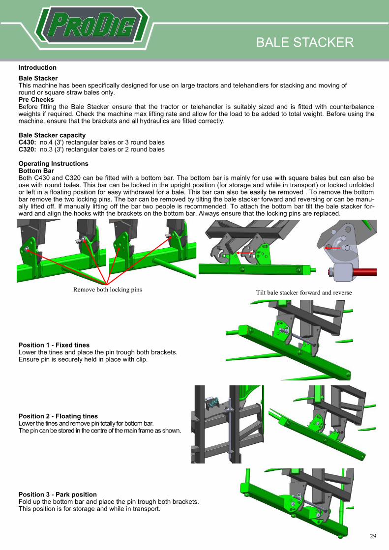
Bale Stacker This machine has been specifically designed for use on large tractors and telehandlers for stacking and moving of round or square straw bales only. Pre Checks Before fitting the Bale Stacker ensure that the tractor or telehandler is suitably sized and is fitted with counterbalance weights if required. Check the machine max lifting rate and allow for the load to be added to total weight. Before using the machine, ensure that the brackets and all hydraulics are fitted correctly. Bale Stacker capacity C430: no.4 (3') rectangular bales or 3 round bales C320: no.3 (3') rectangular bales or 2 round bales Operating Instructions Bottom Bar Both C430 and C320 can be fitted with a bottom bar. The bottom bar is mainly for use with square bales but can also be use with round bales. This bar can be locked in the upright position (for storage and while in transport) or locked unfolded or left in a floating position for easy withdrawal for a bale. This bar can also be easily be removed . To remove the bottom bar remove the two locking pins. The bar can be removed by tilting the bale stacker forward and reversing or can be manu-ally lifted off. If manually lifting off the bar two people is recommended. To attach the bottom bar tilt the bale stacker for-ward and align the hooks with the brackets on the bottom bar. Always ensure that the locking pins are replaced.
Position 1 - Fixed tines Lower the tines and place the pin trough both brackets. Ensure pin is securely held in place with clip. Position 2 - Floating tines Lower the tines and remove pin totally for bottom bar. The pin can be stored in the centre of the main frame as shown. Position 3 - Park position Fold up the bottom bar and place the pin trough both brackets. This position is for storage and while in transport.
BALE STACKER
Remove both locking pins Tilt bale stacker forward and reverse
30
30
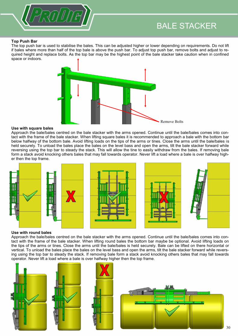
Top Push Bar The top push bar is used to stabilise the bales. This can be adjusted higher or lower depending on requirements. Do not lift if bales where more than half of the top bale is above the push bar. To adjust top push bar, remove bolts and adjust to re-quired height and replace bolts. As the top bar may be the highest point of the bale stacker take caution when in confined space or indoors. Use with square bales Approach the bale/bales centred on the bale stacker with the arms opened. Continue until the bale/bales comes into con-tact with the frame of the bale stacker. When lifting square bales it is recommended to approach a bale with the bottom bar below halfway of the bottom bale. Avoid lifting loads on the tips of the arms or tines. Close the arms until the bale/bales is held securely. To unload the bales place the bales on the level bass and open the arms, tilt the bale stacker forward while reversing using the top bar to steady the stack. This will allow the tine to easily withdraw from the bales. If removing bale form a stack avoid knocking others bales that may fall towards operator. Never lift a load where a bale is over halfway high-er then the top frame.
Use with round bales Approach the bale/bales centred on the bale stacker with the arms opened. Continue until the bale/bales comes into con-tact with the frame of the bale stacker. When lifting round bales the bottom bar maybe be optional. Avoid lifting loads on the tips of the arms or tines. Close the arms until the bale/bales is held securely. Bale can be lifted on there horizontal or vertical. To unload the bales place the bales on the level bass and open the arms, tilt the bale stacker forward while revers-ing using the top bar to steady the stack. If removing bale form a stack avoid knocking others bales that may fall towards operator. Never lift a load where a bale is over halfway higher then the top frame.
Remove Bolts
BALE STACKER
31
31
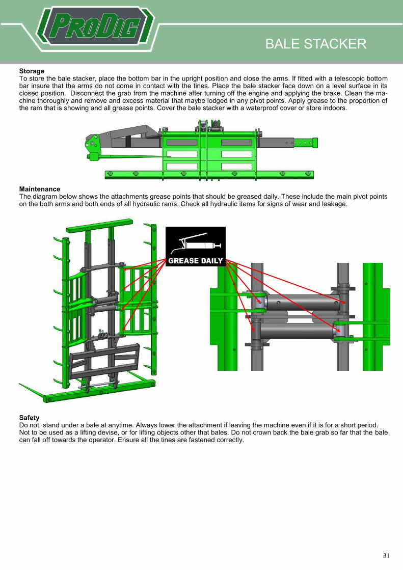
Storage To store the bale stacker, place the bottom bar in the upright position and close the arms. If fitted with a telescopic bottom bar insure that the arms do not come in contact with the tines. Place the bale stacker face down on a level surface in its closed position. Disconnect the grab from the machine after turning off the engine and applying the brake. Clean the ma-chine thoroughly and remove and excess material that maybe lodged in any pivot points. Apply grease to the proportion of the ram that is showing and all grease points. Cover the bale stacker with a waterproof cover or store indoors. Maintenance The diagram below shows the attachments grease points that should be greased daily. These include the main pivot points on the both arms and both ends of all hydraulic rams. Check all hydraulic items for signs of wear and leakage. Safety Do not stand under a bale at anytime. Always lower the attachment if leaving the machine even if it is for a short period. Not to be used as a lifting devise, or for lifting objects other that bales. Do not crown back the bale grab so far that the bale can fall off towards the operator. Ensure all the tines are fastened correctly.
BALE STACKER
32
32
FOLDING GRASS FORK
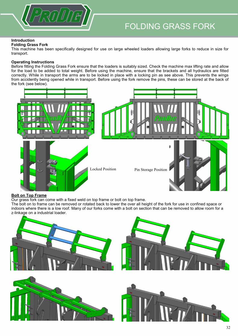
Introduction Folding Grass Fork This machine has been specifically designed for use on large wheeled loaders allowing large forks to reduce in size for transport. Operating Instructions Before fitting the Folding Grass Fork ensure that the loaders is suitably sized. Check the machine max lifting rate and allow for the load to be added to total weight. Before using the machine, ensure that the brackets and all hydraulics are fitted correctly. While in transport the arms are to be locked in place with a locking pin as see above. This prevents the wings from accidently being opened while in transport. Before using the fork remove the pins, these can be stored at the back of the fork (see below).
Locked Position Pin Storage Position
Bolt on Top Frame Our grass fork can come with a fixed weld on top frame or bolt on top frame. The bolt on to frame can be removed or rotated back to lower the over all height of the fork for use in confined space or indoors where there is a low roof. Many of our forks come with a bolt on section that can be removed to allow room for a z-linkage on a industrial loader.
33
33
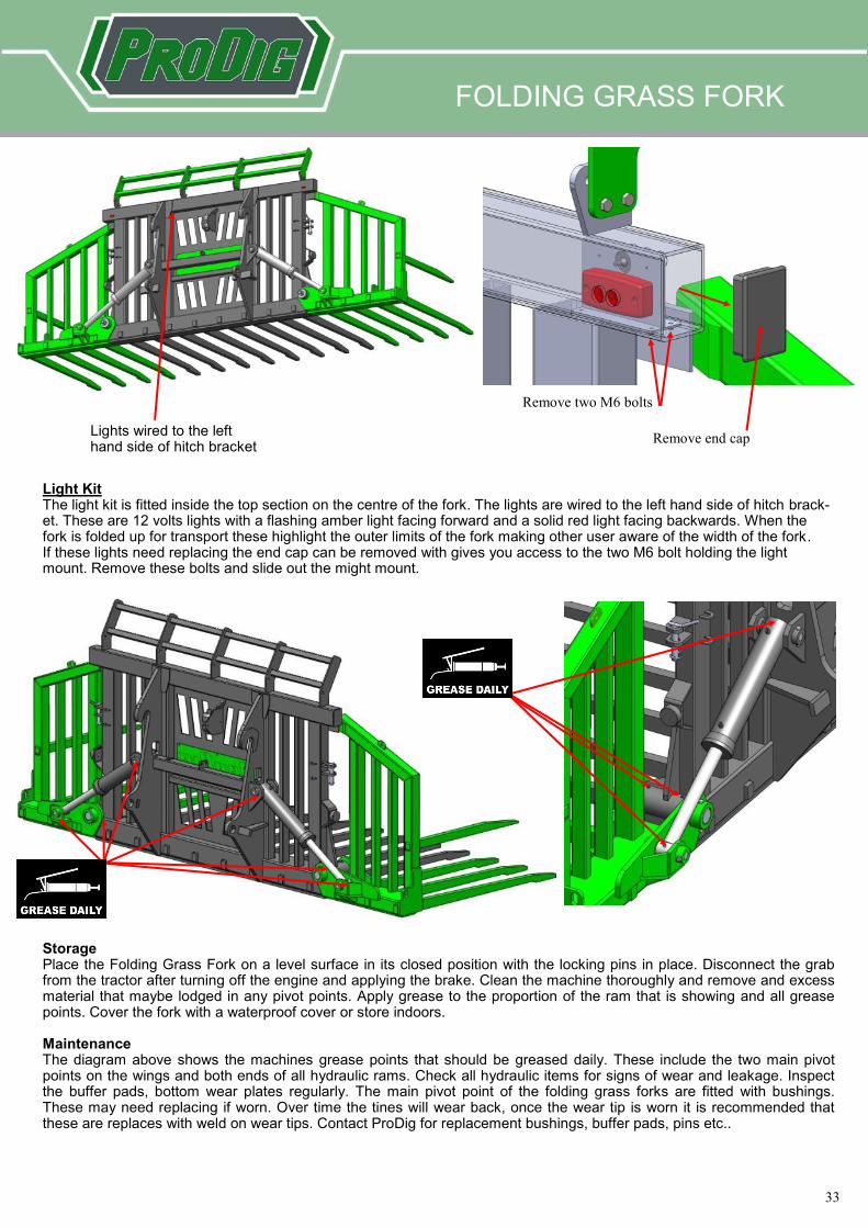
Storage Place the Folding Grass Fork on a level surface in its closed position with the locking pins in place. Disconnect the grab from the tractor after turning off the engine and applying the brake. Clean the machine thoroughly and remove and excess material that maybe lodged in any pivot points. Apply grease to the proportion of the ram that is showing and all grease points. Cover the fork with a waterproof cover or store indoors. Maintenance The diagram above shows the machines grease points that should be greased daily. These include the two main pivot points on the wings and both ends of all hydraulic rams. Check all hydraulic items for signs of wear and leakage. Inspect the buffer pads, bottom wear plates regularly. The main pivot point of the folding grass forks are fitted with bushings. These may need replacing if worn. Over time the tines will wear back, once the wear tip is worn it is recommended that these are replaces with weld on wear tips. Contact ProDig for replacement bushings, buffer pads, pins etc..
Lights wired to the left hand side of hitch bracket
Remove two M6 bolts
Remove end cap
Light Kit The light kit is fitted inside the top section on the centre of the fork. The lights are wired to the left hand side of hitch brack-et. These are 12 volts lights with a flashing amber light facing forward and a solid red light facing backwards. When the fork is folded up for transport these highlight the outer limits of the fork making other user aware of the width of the fork. If these lights need replacing the end cap can be removed with gives you access to the two M6 bolt holding the light mount. Remove these bolts and slide out the might mount.
FOLDING GRASS FORK
34
34
PUSH OFF GRASS FORK
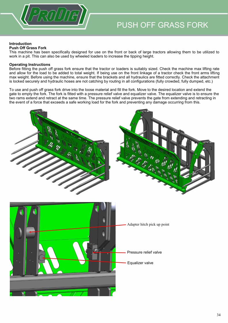
Introduction Push Off Grass Fork This machine has been specifically designed for use on the front or back of large tractors allowing them to be utilized to work in a pit. This can also be used by wheeled loaders to increase the tipping height. Operating Instructions Before fitting the push off grass fork ensure that the tractor or loaders is suitably sized. Check the machine max lifting rate and allow for the load to be added to total weight. If being use on the front linkage of a tractor check the front arms lifting max weight. Before using the machine, ensure that the brackets and all hydraulics are fitted correctly. Check the attachment is locked securely and hydraulic hoses are not catching by routing in all configurations (fully crowded, fully dumped, etc.) To use and push off grass fork drive into the loose material and fill the fork. Move to the desired location and extend the gate to empty the fork. The fork is fitted with a pressure relief valve and equalizer valve. The equalizer valve is to ensure the two rams extend and retract at the same time. The pressure relief valve prevents the gate from extending and retracting in the event of a force that exceeds a safe working load for the fork and preventing any damage occurring from this.
Pressure relief valve
Equalizer valve
Adapter hitch pick up point
35
35
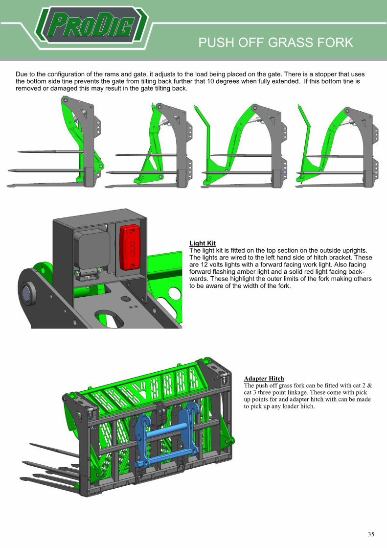
Due to the configuration of the rams and gate, it adjusts to the load being placed on the gate. There is a stopper that uses the bottom side tine prevents the gate from tilting back further that 10 degrees when fully extended. If this bottom tine is removed or damaged this may result in the gate tilting back.
Light Kit The light kit is fitted on the top section on the outside uprights. The lights are wired to the left hand side of hitch bracket. These are 12 volts lights with a forward facing work light. Also facing forward flashing amber light and a solid red light facing back-wards. These highlight the outer limits of the fork making others to be aware of the width of the fork.
Adapter Hitch The push off grass fork can be fitted with cat 2 & cat 3 three point linkage. These come with pick up points for and adapter hitch with can be made to pick up any loader hitch.
PUSH OFF GRASS FORK
36
36
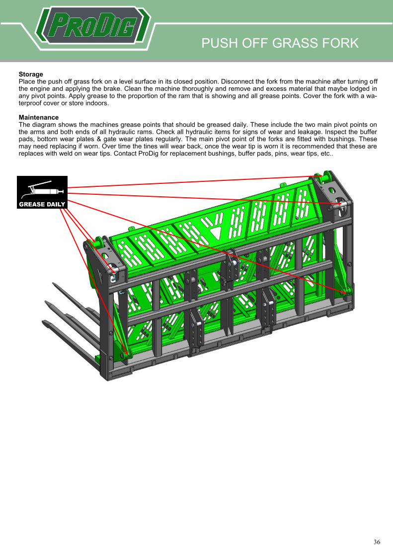
Storage Place the push off grass fork on a level surface in its closed position. Disconnect the fork from the machine after turning off the engine and applying the brake. Clean the machine thoroughly and remove and excess material that maybe lodged in any pivot points. Apply grease to the proportion of the ram that is showing and all grease points. Cover the fork with a wa-terproof cover or store indoors. Maintenance The diagram shows the machines grease points that should be greased daily. These include the two main pivot points on the arms and both ends of all hydraulic rams. Check all hydraulic items for signs of wear and leakage. Inspect the buffer pads, bottom wear plates & gate wear plates regularly. The main pivot point of the forks are fitted with bushings. These may need replacing if worn. Over time the tines will wear back, once the wear tip is worn it is recommended that these are replaces with weld on wear tips. Contact ProDig for replacement bushings, buffer pads, pins, wear tips, etc..
PUSH OFF GRASS FORK
37
37
PROSWEEP
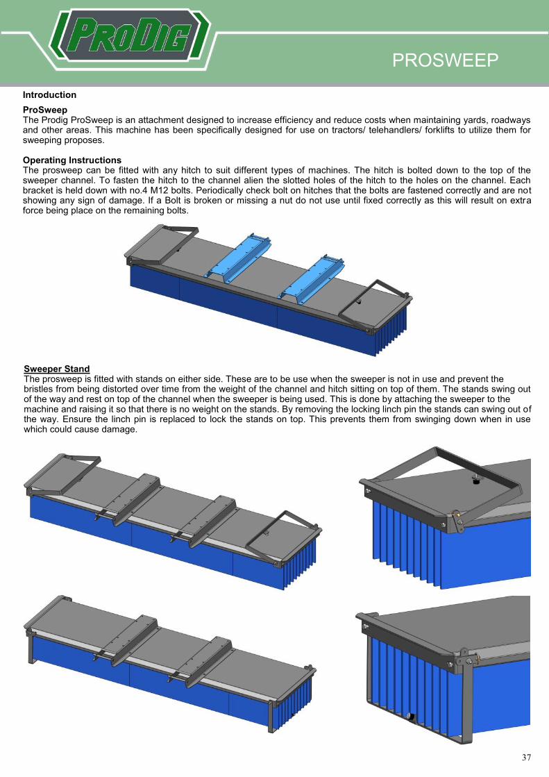
Introduction
ProSweep The Prodig ProSweep is an attachment designed to increase efficiency and reduce costs when maintaining yards, roadways and other areas. This machine has been specifically designed for use on tractors/ telehandlers/ forklifts to utilize them for sweeping proposes. Operating Instructions The prosweep can be fitted with any hitch to suit different types of machines. The hitch is bolted down to the top of the sweeper channel. To fasten the hitch to the channel alien the slotted holes of the hitch to the holes on the channel. Each bracket is held down with no.4 M12 bolts. Periodically check bolt on hitches that the bolts are fastened correctly and are not showing any sign of damage. If a Bolt is broken or missing a nut do not use until fixed correctly as this will result on extra force being place on the remaining bolts.
Sweeper Stand The prosweep is fitted with stands on either side. These are to be use when the sweeper is not in use and prevent the bristles from being distorted over time from the weight of the channel and hitch sitting on top of them. The stands swing out of the way and rest on top of the channel when the sweeper is being used. This is done by attaching the sweeper to the machine and raising it so that there is no weight on the stands. By removing the locking linch pin the stands can swing out of the way. Ensure the linch pin is replaced to lock the stands on top. This prevents them from swinging down when in use which could cause damage.
38
38
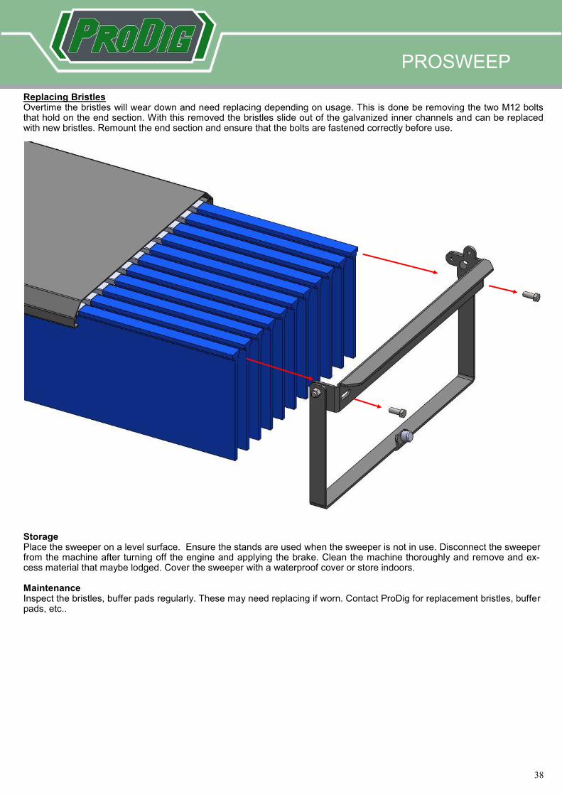
Replacing Bristles Overtime the bristles will wear down and need replacing depending on usage. This is done be removing the two M12 bolts that hold on the end section. With this removed the bristles slide out of the galvanized inner channels and can be replaced with new bristles. Remount the end section and ensure that the bolts are fastened correctly before use.
Storage Place the sweeper on a level surface. Ensure the stands are used when the sweeper is not in use. Disconnect the sweeper from the machine after turning off the engine and applying the brake. Clean the machine thoroughly and remove and ex-cess material that maybe lodged. Cover the sweeper with a waterproof cover or store indoors. Maintenance Inspect the bristles, buffer pads regularly. These may need replacing if worn. Contact ProDig for replacement bristles, buffer pads, etc..
PROSWEEP
39
39
OTHER ATTACHMENTS
Introduction
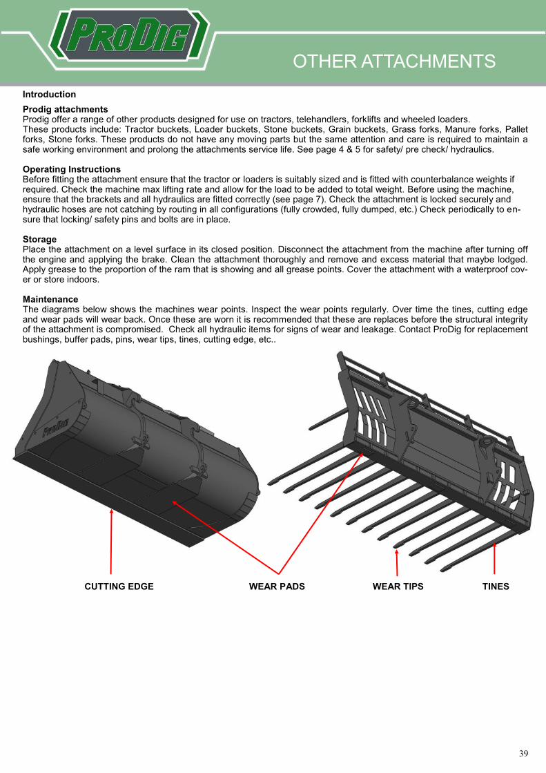
Prodig attachments Prodig offer a range of other products designed for use on tractors, telehandlers, forklifts and wheeled loaders. These products include: Tractor buckets, Loader buckets, Stone buckets, Grain buckets, Grass forks, Manure forks, Pallet forks, Stone forks. These products do not have any moving parts but the same attention and care is required to maintain a safe working environment and prolong the attachments service life. See page 4 & 5 for safety/ pre check/ hydraulics. Operating Instructions Before fitting the attachment ensure that the tractor or loaders is suitably sized and is fitted with counterbalance weights if required. Check the machine max lifting rate and allow for the load to be added to total weight. Before using the machine, ensure that the brackets and all hydraulics are fitted correctly (see page 7). Check the attachment is locked securely and hydraulic hoses are not catching by routing in all configurations (fully crowded, fully dumped, etc.) Check periodically to en-sure that locking/ safety pins and bolts are in place. Storage Place the attachment on a level surface in its closed position. Disconnect the attachment from the machine after turning off the engine and applying the brake. Clean the attachment thoroughly and remove and excess material that maybe lodged. Apply grease to the proportion of the ram that is showing and all grease points. Cover the attachment with a waterproof cov-er or store indoors. Maintenance The diagrams below shows the machines wear points. Inspect the wear points regularly. Over time the tines, cutting edge and wear pads will wear back. Once these are worn it is recommended that these are replaces before the structural integrity of the attachment is compromised. Check all hydraulic items for signs of wear and leakage. Contact ProDig for replacement bushings, buffer pads, pins, wear tips, tines, cutting edge, etc..
CUTTING EDGE WEAR TIPS WEAR PADS TINES
40
40
Storage
Place the Mega Bite on a level surface. Disconnect the Mega Bite from the machine after turning off the
engine and applying the brake. Clean the Mega Bite thoroughly. Cover the grab with a waterproof cover or
store inside. Apply grease to blade surfaces and hydraulic cylinder chrome rod (figure 11) when laid up
for a period of time along with all grease points. Access to the ram on plastic gripper for greasing can be
obtained from the rer of the mega bite (figure 12).