Embed Size (px)
Citation preview
Systematic Application of UCIS to Improve theAutomation on Verification Closure
Christoph Kuznik, Marcio F. S. Oliveira, Gilles Bertrand Defo, Wolfgang Mueller
Faculty of Electrical Engineering,Computer Science and Mathematics
University of Paderborn/C-LABD-33102 Paderborn, Germany
{kuznik, marcio, bertrand, wolfgang}@upb.de
Abstract—Interoperability between verification flows and toolsis of particular importance for verification engineers and theEDA industry. While UVM and the Unified Coverage Interop-erability Standard (UCIS) target the unified creation and reuseof verification environments, the flow from verification plan totestbench implementation and extraction of coverage data is still atime-consuming and error prone task, for which little automationsupport is available. In this article we present how to implementa coverage plan-driven functional coverage metric generation forSystemC verification environments, by means of UCIS and state-of-the art code generation and Model-driven Engineering (MDE)techniques.
I. INTRODUCTION
As designs have grown, verification closure by means ofcoverage metrics is critical to measure the status and qualityof the verification plan. The verification plan, usually a spread-sheet style document, defines the verification environment,the stimuli generation plan, the coverage plan and more.Moreover, as interoperability of flows and tools is of particularimportance, highly interoperable methodologies for verifica-tion and coverage interchange have been introduced, such asthe Universal Verification Methodology (UVM) [1], and theUnified Coverage Interoperability Standard (UCIS) [2]. WhileUVM provides the verification engineer with elements to buildreusable testbenches with expected structure, UCIS defines aschema for creation, merge and export of coverage informationacross simulators and languages, eased by a convenient API.
In order to use those technical advances with the OSCISystemC reference simulator we developed the System Ver-ification Methodology (SVM) [3] in previous work, which isa verification methodology for the OSCI SystemC referencesimulator inspired by UVM. Besides, SVM integrates also apreviously developed functional coverage library [4].
Focusing on the verification environment construction andprocess, we propose the verification plan preparation and itsexploitation to leverage from a systematic application of UCIS.Therefore, we(1) introduce the systematic collection of coverage plan data,
while preserving the language independence.(2) utilize UCIS to store the coverage plan metrics for the
DUV in an interoperable format — a UCIS model.
By means of a Model-Driven Engineering (MDE) tech-nology the UCIS metrics model is mapped to a designmodel, combining both models for further analysis and code-generation. Afterward, the corresponding SystemC testbenchinfrastructure for the DUV is generated using our SVM library.During the simulation run the UCIS database is filled withactual coverage information, gathered from the simulation run.
The remainder of article is structured as follows. Section IIwill present fundamentals such as UCIS, our previous workand an overview about terms used in MDE. Section III willintroduce our contribution in more detail. Section IV shows adetailed step-by-step explanation of the workflow by means ofan example system. Related work will be referenced in sectionV. Section VI will discuss the limitations of our methodologyand lessons learned from the application of UCIS, before wesummarize and draw conclusions in section VII.
II. FUNDAMENTALS
A. Unified Coverage Interoperability Standard
The UCIS [2] has been developed to allow the coveragemetric interchange of a variety of coverage producers, fromstatement coverage and functional coverage to formal. There-fore, an analysis on the information model of verification hasbeen conducted by Accellera and a subset was selected andmapped to a data model, the UCIS data model, being ableto represent a range of coverage information models used inpractice. A standardized mapping, naming conventions andprimary key management make the data objects universallyrecognizable. Besides, an API was defined that standardizesthe way data is written or queried from this data model. Theofficial Accellera UCIS v1.0 standard release provides:
• UCIS Specification v1.0, describing the API functionsand the underlying data model.
• UCIS API Header File (.h), to allow custom implemen-tations of coverage producers and consumers.
• UCIS XML schema, as formal definition of the inter-change format.
The UCIS specification lists a number of use models. First,coverage producers may use UCIS to generate data. Second,
Version 1.0 Unified Coverage Interoperability Standard 59
Figure 8—Functional and Code Coverage Scopes
If a scope or coveritem type is not mentioned or listed here, this standard has not defined a universal objectrecognition model for it. This can be because the structures and names are assumed to be inherited from some otherstandardized domain, such as a language reference manual. Alternatively, there may be types for which there is nogenerally-accepted information model.
Neither case prevents a coverage generation tool from creating data with this type, or a consumption tool from actingon the data to the degree to which it can understand it. It may however require extra analysis from tools attempting toreconcile data of this type across tools or vendors.
UCIS_COV_SCOPE
UCIS_CODE_COV_SCOPEUCIS_FUNC_COV_SCOPE
UCIS_CVG_SCOPE
UCIS_FSM_SCOPE
UCIS_VERIF_SCOPE
UCIS_FSM
UCIS_FSM_STATES
UCIS_FSM_TRANSUCIS_COVER
UCIS_IGNOREBINSCOPE
UCIS_ILLEGALBINSCOPE
UCIS_CROSS
UCIS_COVERINSTANCE
UCIS_COVERPOINT
UCIS_COVERGROUP
UCIS_CVGBINSCOPE
UCIS_BRANCH
UCIS_EXPR
UCIS_COND
UCIS_TOGGLE
UCIS_COVBLOCK
UCIS_ASSERT UCIS_GENERIC
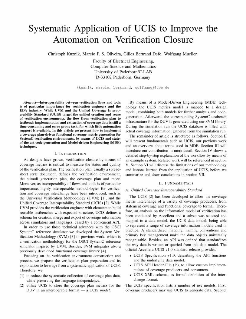
Fig. 1: The UCIS coverage scopes may contain coverageinformation from various coverage producers [2].
coverage consumers may facilitate the API and the interchangeformat to perform analysis tasks such as report generation ortest plan update. Moreover, the activity to combine coverageresults from independent simulation runs (temporal merge orspatial merge) or from different coverage producers (heteroge-neous merge) is another specified use case. By means of theUCIS API, standardized interface names for creating, readingand merging coverage metric databases are provided. Besides,custom features can be implemented using API callbackfunctions.
As UCIS may contain coverage information from variouscoverage data producers such as formal verification, staticchecks, assertions and data coverpoints it can be used to helpin answering both the Does it work? and the Are we done?questions (verification closure). Figure 1 lists the coveragescopes as defined by the Accellera UCIS standard release v1.0.In section III we will introduce how UCIS can additionallyimprove the automation on verification closure by means ofsystematic coverage plan utilization. Moreover, we will focuson the UCIS_CVG_SCOPE coverage scope.
B. SVM - A verification methodology for SystemC
Despite SystemC is widely accepted for development athigher abstraction levels such as TLM 2.0, its verificationcapabilities are rather limited in comparison to other HardwareDesign and Verification languages (HDVL) such as IEEE-1800 SystemVerilog or IEEE-1647 e as can be seen in Ta-ble I. Moreover, in the past verification methodologies weremainly introduced as SystemVerilog implementations, such
TABLE I: Selection of verification features of IEEE-1800,IEEE-1647 and IEEE-1666 compared.
IEEE-1800SystemVerilog
IEEE-1647 e IEEE-1666SystemC
Functional Coverage +++ +++ xAssertions +++ +++ xConstraint Solver +++ +++ + (SCV lib.)Verification Meth. +++ +++ xTLM ++ + +++AOP x ++ xC-Software simulator simulator +++Simulation dependent dependent
as the Universal Reuse Methodology (URM) from Cadence,the Advanced Verification Methodology (AVM) from MentorGraphics, and the Verification Methodology Manual (VMM)from Synopsys.
In order to use recent technical advances within the OSCISystemC reference simulator we developed the SystemC-based System Verification Methodology (SVM) library [5],[3] and a functional coverage library for SystemC [4], [6]in previous work. SVM is based on the Open VerificationMethodology multi-language release (OVM-ML), a donationfrom Cadence Inc. to the OVM community in February 2009[7]. We refactored the base package and further improved itto reflect the improvements from the transition of OVM to theUniversal Verification Methodology (UVM) standard [1]. Wealso extended the limited UVM for SystemC subset to offerthe same expected structure as in SystemVerilog, e.g. allowingusage of stimuli generation facilities, sequences managementand arbitration, command-line processing, etc. with the OSCISystemC reference simulator. Moreover, a functional coveragelibrary has been integrated into SVM and implements parts ofthe IEEE 1800-2009 SystemVerilog covergroup functionalcoverage metric to allow coverage-driven-verification (CDV)using the standard OSCI SystemC reference simulator.
Consequently, testbench automation approaches, e.g. codegeneration, for SystemC can now benefit from these improvedverification capabilities. Based on the two introduced contribu-tions we now intend to improve the automation on verificationclosure within the verification process with SystemC itself.
C. Model-driven Engineering (MDE)
As most part of a verification testbench is software sourcecode containing classes, objects and function calls, we ad-vocate the application of MDE, in order to improve thedevelopment of testbenches and the verification process. MDEwas proposed to overcome the limitations of object technology,to rise the abstraction and deal with the increasingly morecomplex and rapidly evolving systems.
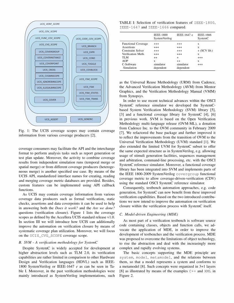
The basic concepts supporting the MDE principle aresystem, model, metamodel, and the relations betweenthem, so that a model represents a system and conforms toa metamodel [8]. Such concepts were organized in 3+1 layers[8] as illustrated by means of the examples C++ and XML inFigure 2.
Metamodel
Model
System
Metametamodel
Conforms to
Conforms to
Conforms to
Represents
M3
M2
M1
M0
C++ Grammar
C++ Source Code
System
BNF
Conforms to
Conforms to
Conforms to
Represents
User defined XML Schema
XML Document
System
XML Schema
Conforms to
Conforms to
Conforms to
Represents
Fig. 2: Basic concepts, layered organization and relation ofmodel and metamodel with C++ and XML as examples.
The UCIS metamodel
A metamodel is also a model, which is a reference model forother models, so that it defines classes of models that can beproduced conforming to it. It is an abstraction, which collectsconcepts of a certain domain and the relations between theseconcepts. As such, the UCIS data model can be used to definethe metamodel for the coverage domain. Therefore, we usethe UCIS XML schema to generate the UCIS metamodel inour methodology.
Transformations
MDE models are operated through transformations, aimingat the automation of development activity. Such transforma-tions define clear relationships between models [8] and usuallyare specified in a specialized language to operate on models.Following the description in [9], a model transformation meansconverting one or more source models to a target model, whereall models must conform to some metamodel, including themodel transformation itself, which is also a model.
Available tooling to enable MDE
MDE Technological frameworks [10] are tools to supportcommon tasks for MDE independently from the applicationdomain. Such tools rely on standards, in order to generalizethe manipulation of models, providing facilities such as persis-tence, repository management, model transformation, modelmapping (weaving), etc. They are the technological supportfor the MDE principles. For working with the UCIS XMLand UCIS metamodel we use the framework provided byEclipse Modeling Project1 (EMP) to provide tool support forour methodology.
1http://www.eclipse.org/modeling/
Questa SIM User’s Manual, v10.1a1114
Coverage and Verification Management in the UCDBCoverage and Verification Overview
Retrieving Test Attribute Record Content . . . . . . . . . . . . . . . . . . . . . . . . . . . . . . . . . . . . . 1160
Coverage and Verification Overview• the merging and aggregation of coverage data
• ranking of tests
• ranking of tests within a test plan
• analysis of coverage in light of late-stage ECO’s
• test and command re-runs
• various analyses of coverage data
• generation of easy-to-read HTML coverage reports
The flow described in Figure 25-1 represents a typical design verification process as it can be applied in the Questa SIM environment.
Figure 25-1. Verification of a Design
Done
Modify Stimulus
Debug DesignDoes it Work?
DesignSpecification
DesignImplementation
VerificationPlan
Test Bench Simulate
Are we Done?
No
Yes
Yes
No
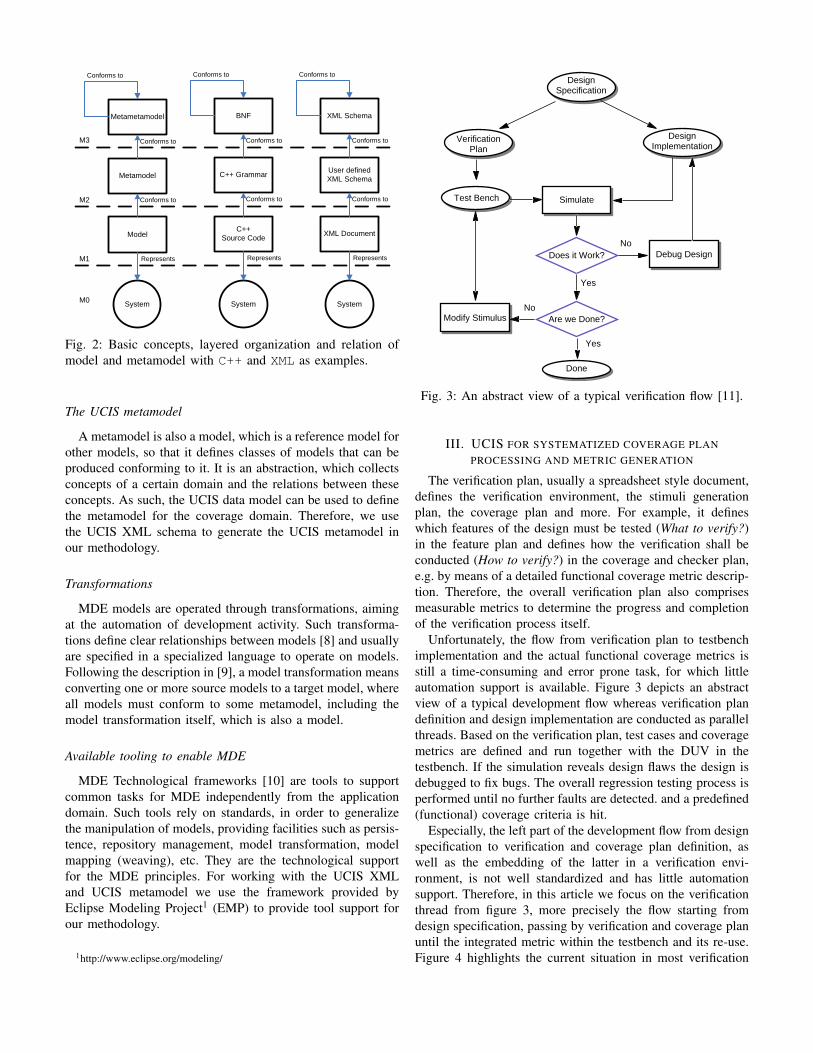
Fig. 3: An abstract view of a typical verification flow [11].
III. UCIS FOR SYSTEMATIZED COVERAGE PLANPROCESSING AND METRIC GENERATION
The verification plan, usually a spreadsheet style document,defines the verification environment, the stimuli generationplan, the coverage plan and more. For example, it defineswhich features of the design must be tested (What to verify?)in the feature plan and defines how the verification shall beconducted (How to verify?) in the coverage and checker plan,e.g. by means of a detailed functional coverage metric descrip-tion. Therefore, the overall verification plan also comprisesmeasurable metrics to determine the progress and completionof the verification process itself.
Unfortunately, the flow from verification plan to testbenchimplementation and the actual functional coverage metrics isstill a time-consuming and error prone task, for which littleautomation support is available. Figure 3 depicts an abstractview of a typical development flow whereas verification plandefinition and design implementation are conducted as parallelthreads. Based on the verification plan, test cases and coveragemetrics are defined and run together with the DUV in thetestbench. If the simulation reveals design flaws the design isdebugged to fix bugs. The overall regression testing process isperformed until no further faults are detected. and a predefined(functional) coverage criteria is hit.
Especially, the left part of the development flow from designspecification to verification and coverage plan definition, aswell as the embedding of the latter in a verification envi-ronment, is not well standardized and has little automationsupport. Therefore, in this article we focus on the verificationthread from figure 3, more precisely the flow starting fromdesign specification, passing by verification and coverage planuntil the integrated metric within the testbench and its re-use.Figure 4 highlights the current situation in most verification
Verification Plan(in particular: Coverage Plan)
Specification
Verification Environment
(in particular: Func.
Coverage Metrics)
Implementation
Verification Planwith
systematized Coverage Plan
Specification
Feature List
Coverage Plan
Checker Plan
ScheduleVerification
Environment(Func. Metrics
generated)
Implementation1
3
4
Feature List
Coverage Plan
Checker Plan
Schedule
insufficient automation support, error-prone manual tasks
manually manually
systematizedassisted / automatized
systematizedassisted / automatized
2
Improved automation, soundness
Fig. 4: Low automation support for coverage plan implemen-tation due to informal manual conversions.
Verification Plan(in particular: Coverage Plan)
Specification
Verification Environment
(in particular: Func.
Coverage Metrics)
Implementation
Verification Planwith
systematized Coverage Plan
Specification
Feature List
Coverage Plan
Checker Plan
Schedule
Verification Environment
(Func. Metrics
generated)
Implementation
1
3
4
Feature List
Coverage Plan
Checker Plan
Schedule
insufficient automation support, error-prone manual tasks
manually manually
systematizedassisted /
automatized
systematizedassisted /
automatized
2
Improved automation, soundness
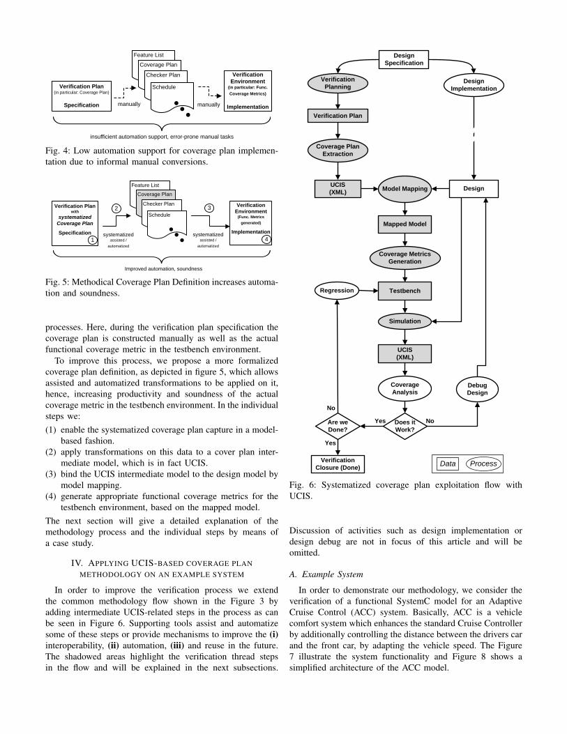
Fig. 5: Methodical Coverage Plan Definition increases automa-tion and soundness.
processes. Here, during the verification plan specification thecoverage plan is constructed manually as well as the actualfunctional coverage metric in the testbench environment.
To improve this process, we propose a more formalizedcoverage plan definition, as depicted in figure 5, which allowsassisted and automatized transformations to be applied on it,hence, increasing productivity and soundness of the actualcoverage metric in the testbench environment. In the individualsteps we:(1) enable the systematized coverage plan capture in a model-
based fashion.(2) apply transformations on this data to a cover plan inter-
mediate model, which is in fact UCIS.(3) bind the UCIS intermediate model to the design model by
model mapping.(4) generate appropriate functional coverage metrics for the
testbench environment, based on the mapped model.The next section will give a detailed explanation of themethodology process and the individual steps by means ofa case study.
IV. APPLYING UCIS-BASED COVERAGE PLANMETHODOLOGY ON AN EXAMPLE SYSTEM
In order to improve the verification process we extendthe common methodology flow shown in the Figure 3 byadding intermediate UCIS-related steps in the process as canbe seen in Figure 6. Supporting tools assist and automatizesome of these steps or provide mechanisms to improve the (i)interoperability, (ii) automation, (iii) and reuse in the future.The shadowed areas highlight the verification thread stepsin the flow and will be explained in the next subsections.
Design UCIS(XML)
Does it Work?
Are we Done?
Yes
No
NoYes
VerificationClosure (Done)
Verification Planning
Coverage Plan Extraction
Coverage Metrics Generation
Simulation
Debug Design
Regression
Design Specification
Verification Plan
Design Implementation
Model Mapping
Mapped Model
Testbench
UCIS(XML)
Coverage Analysis
Data Process
Fig. 6: Systematized coverage plan exploitation flow withUCIS.
Discussion of activities such as design implementation ordesign debug are not in focus of this article and will beomitted.
A. Example System
In order to demonstrate our methodology, we consider theverification of a functional SystemC model for an AdaptiveCruise Control (ACC) system. Basically, ACC is a vehiclecomfort system which enhances the standard Cruise Controllerby additionally controlling the distance between the drivers carand the front car, by adapting the vehicle speed. The Figure7 illustrate the system functionality and Figure 8 shows asimplified architecture of the ACC model.
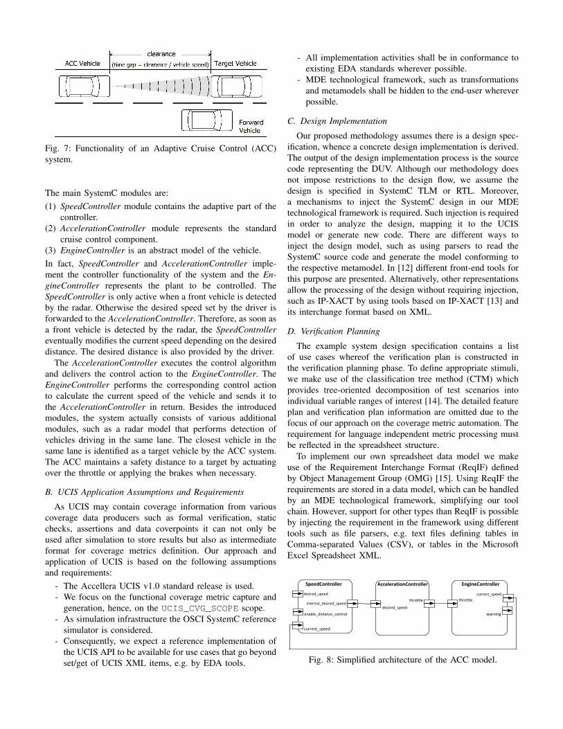
Fig. 7: Functionality of an Adaptive Cruise Control (ACC)system.
The main SystemC modules are:(1) SpeedController module contains the adaptive part of the
controller.(2) AccelerationController module represents the standard
cruise control component.(3) EngineController is an abstract model of the vehicle.In fact, SpeedController and AccelerationController imple-ment the controller functionality of the system and the En-gineController represents the plant to be controlled. TheSpeedController is only active when a front vehicle is detectedby the radar. Otherwise the desired speed set by the driver isforwarded to the AccelerationController. Therefore, as soon asa front vehicle is detected by the radar, the SpeedControllereventually modifies the current speed depending on the desireddistance. The desired distance is also provided by the driver.
The AccelerationController executes the control algorithmand delivers the control action to the EngineController. TheEngineController performs the corresponding control actionto calculate the current speed of the vehicle and sends it tothe AccelerationController in return. Besides the introducedmodules, the system actually consists of various additionalmodules, such as a radar model that performs detection ofvehicles driving in the same lane. The closest vehicle in thesame lane is identified as a target vehicle by the ACC system.The ACC maintains a safety distance to a target by actuatingover the throttle or applying the brakes when necessary.
B. UCIS Application Assumptions and Requirements
As UCIS may contain coverage information from variouscoverage data producers such as formal verification, staticchecks, assertions and data coverpoints it can not only beused after simulation to store results but also as intermediateformat for coverage metrics definition. Our approach andapplication of UCIS is based on the following assumptionsand requirements:
- The Accellera UCIS v1.0 standard release is used.- We focus on the functional coverage metric capture and
generation, hence, on the UCIS_CVG_SCOPE scope.- As simulation infrastructure the OSCI SystemC reference
simulator is considered.- Consequently, we expect a reference implementation of
the UCIS API to be available for use cases that go beyondset/get of UCIS XML items, e.g. by EDA tools.
- All implementation activities shall be in conformance toexisting EDA standards wherever possible.
- MDE technological framework, such as transformationsand metamodels shall be hidden to the end-user whereverpossible.
C. Design Implementation
Our proposed methodology assumes there is a design spec-ification, whence a concrete design implementation is derived.The output of the design implementation process is the sourcecode representing the DUV. Although our methodology doesnot impose restrictions to the design flow, we assume thedesign is specified in SystemC TLM or RTL. Moreover,a mechanisms to inject the SystemC design in our MDEtechnological framework is required. Such injection is requiredin order to analyze the design, mapping it to the UCISmodel or generate new code. There are different ways toinject the design model, such as using parsers to read theSystemC source code and generate the model conforming tothe respective metamodel. In [12] different front-end tools forthis purpose are presented. Alternatively, other representationsallow the processing of the design without requiring injection,such as IP-XACT by using tools based on IP-XACT [13] andits interchange format based on XML.
D. Verification Planning
The example system design specification contains a listof use cases whereof the verification plan is constructed inthe verification planning phase. To define appropriate stimuli,we make use of the classification tree method (CTM) whichprovides tree-oriented decomposition of test scenarios intoindividual variable ranges of interest [14]. The detailed featureplan and verification plan information are omitted due to thefocus of our approach on the coverage metric automation. Therequirement for language independent metric processing mustbe reflected in the spreadsheet structure.
To implement our own spreadsheet data model we makeuse of the Requirement Interchange Format (ReqIF) definedby Object Management Group (OMG) [15]. Using ReqIF therequirements are stored in a data model, which can be handledby an MDE technological framework, simplifying our toolchain. However, support for other types than ReqIF is possibleby injecting the requirement in the framework using differenttools such as file parsers, e.g. text files defining tables inComma-separated Values (CSV), or tables in the MicrosoftExcel Spreadsheet XML.
SpeedController
desired_speed
internal_desired_speed
enable_distance_control
EngineController
current_speedthrottle
AccelerationController
throttle
current_speed
desired_speed
warning
Fig. 8: Simplified architecture of the ACC model.
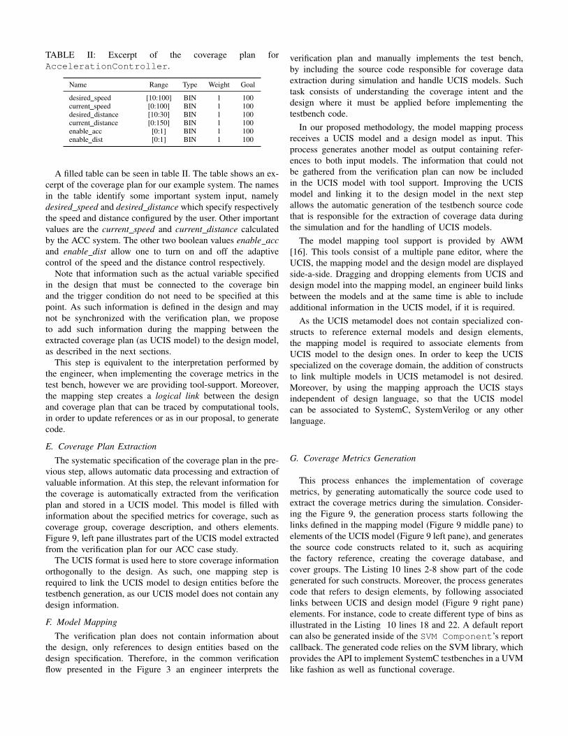
TABLE II: Excerpt of the coverage plan forAccelerationController.
Name Range Type Weight Goal
desired speed [10:100] BIN 1 100current speed [0:100] BIN 1 100desired distance [10:30] BIN 1 100current distance [0:150] BIN 1 100enable acc [0:1] BIN 1 100enable dist [0:1] BIN 1 100
A filled table can be seen in table II. The table shows an ex-cerpt of the coverage plan for our example system. The namesin the table identify some important system input, namelydesired speed and desired distance which specify respectivelythe speed and distance configured by the user. Other importantvalues are the current speed and current distance calculatedby the ACC system. The other two boolean values enable accand enable dist allow one to turn on and off the adaptivecontrol of the speed and the distance control respectively.
Note that information such as the actual variable specifiedin the design that must be connected to the coverage binand the trigger condition do not need to be specified at thispoint. As such information is defined in the design and maynot be synchronized with the verification plan, we proposeto add such information during the mapping between theextracted coverage plan (as UCIS model) to the design model,as described in the next sections.
This step is equivalent to the interpretation performed bythe engineer, when implementing the coverage metrics in thetest bench, however we are providing tool-support. Moreover,the mapping step creates a logical link between the designand coverage plan that can be traced by computational tools,in order to update references or as in our proposal, to generatecode.
E. Coverage Plan Extraction
The systematic specification of the coverage plan in the pre-vious step, allows automatic data processing and extraction ofvaluable information. At this step, the relevant information forthe coverage is automatically extracted from the verificationplan and stored in a UCIS model. This model is filled withinformation about the specified metrics for coverage, such ascoverage group, coverage description, and others elements.Figure 9, left pane illustrates part of the UCIS model extractedfrom the verification plan for our ACC case study.
The UCIS format is used here to store coverage informationorthogonally to the design. As such, one mapping step isrequired to link the UCIS model to design entities before thetestbench generation, as our UCIS model does not contain anydesign information.
F. Model Mapping
The verification plan does not contain information aboutthe design, only references to design entities based on thedesign specification. Therefore, in the common verificationflow presented in the Figure 3 an engineer interprets the
verification plan and manually implements the test bench,by including the source code responsible for coverage dataextraction during simulation and handle UCIS models. Suchtask consists of understanding the coverage intent and thedesign where it must be applied before implementing thetestbench code.
In our proposed methodology, the model mapping processreceives a UCIS model and a design model as input. Thisprocess generates another model as output containing refer-ences to both input models. The information that could notbe gathered from the verification plan can now be includedin the UCIS model with tool support. Improving the UCISmodel and linking it to the design model in the next stepallows the automatic generation of the testbench source codethat is responsible for the extraction of coverage data duringthe simulation and for the handling of UCIS models.
The model mapping tool support is provided by AWM[16]. This tools consist of a multiple pane editor, where theUCIS, the mapping model and the design model are displayedside-a-side. Dragging and dropping elements from UCIS anddesign model into the mapping model, an engineer build linksbetween the models and at the same time is able to includeadditional information in the UCIS model, if it is required.
As the UCIS metamodel does not contain specialized con-structs to reference external models and design elements,the mapping model is required to associate elements fromUCIS model to the design ones. In order to keep the UCISspecialized on the coverage domain, the addition of constructsto link multiple models in UCIS metamodel is not desired.Moreover, by using the mapping approach the UCIS staysindependent of design language, so that the UCIS modelcan be associated to SystemC, SystemVerilog or any otherlanguage.
G. Coverage Metrics Generation
This process enhances the implementation of coveragemetrics, by generating automatically the source code used toextract the coverage metrics during the simulation. Consider-ing the Figure 9, the generation process starts following thelinks defined in the mapping model (Figure 9 middle pane) toelements of the UCIS model (Figure 9 left pane), and generatesthe source code constructs related to it, such as acquiringthe factory reference, creating the coverage database, andcover groups. The Listing 10 lines 2-8 show part of the codegenerated for such constructs. Moreover, the process generatescode that refers to design elements, by following associatedlinks between UCIS and design model (Figure 9 right pane)elements. For instance, code to create different type of bins asillustrated in the Listing 10 lines 18 and 22. A default reportcan also be generated inside of the SVM Component’s reportcallback. The generated code relies on the SVM library, whichprovides the API to implement SystemC testbenches in a UVMlike fashion as well as functional coverage.
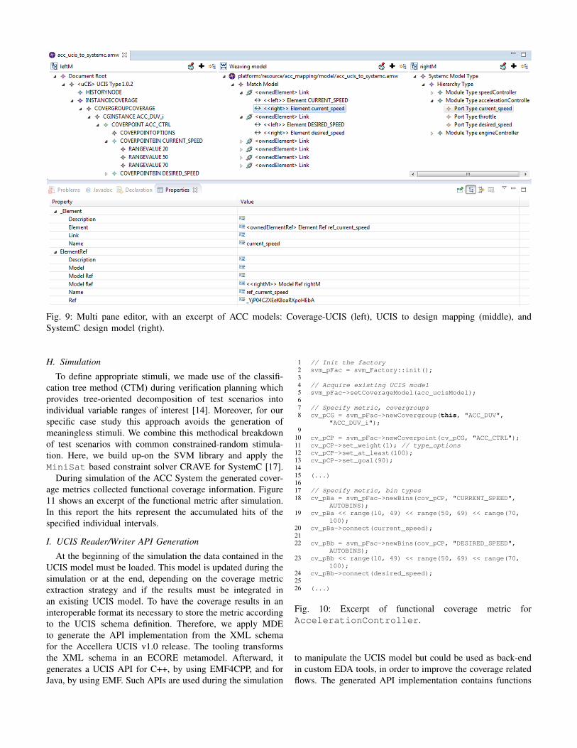
Fig. 9: Multi pane editor, with an excerpt of ACC models: Coverage-UCIS (left), UCIS to design mapping (middle), andSystemC design model (right).
H. Simulation
To define appropriate stimuli, we made use of the classifi-cation tree method (CTM) during verification planning whichprovides tree-oriented decomposition of test scenarios intoindividual variable ranges of interest [14]. Moreover, for ourspecific case study this approach avoids the generation ofmeaningless stimuli. We combine this methodical breakdownof test scenarios with common constrained-random stimula-tion. Here, we build up-on the SVM library and apply theMiniSat based constraint solver CRAVE for SystemC [17].
During simulation of the ACC System the generated cover-age metrics collected functional coverage information. Figure11 shows an excerpt of the functional metric after simulation.In this report the hits represent the accumulated hits of thespecified individual intervals.
I. UCIS Reader/Writer API Generation
At the beginning of the simulation the data contained in theUCIS model must be loaded. This model is updated during thesimulation or at the end, depending on the coverage metricextraction strategy and if the results must be integrated inan existing UCIS model. To have the coverage results in aninteroperable format its necessary to store the metric accordingto the UCIS schema definition. Therefore, we apply MDEto generate the API implementation from the XML schemafor the Accellera UCIS v1.0 release. The tooling transformsthe XML schema in an ECORE metamodel. Afterward, itgenerates a UCIS API for C++, by using EMF4CPP, and forJava, by using EMF. Such APIs are used during the simulation
1 // Init the factory2 svm_pFac = svm_Factory::init();34 // Acquire existing UCIS model5 svm_pFac->setCoverageModel(acc_ucisModel);67 // Specify metric, covergroups8 cv_pCG = svm_pFac->newCovergroup(this, "ACC_DUV",
"ACC_DUV_i");9
10 cv_pCP = svm_pFac->newCoverpoint(cv_pCG, "ACC_CTRL");11 cv_pCP->set_weight(1); // type_options12 cv_pCP->set_at_least(100);13 cv_pCP->set_goal(90);1415 (...)1617 // Specify metric, bin types18 cv_pBa = svm_pFac->newBins(cov_pCP, "CURRENT_SPEED",
AUTOBINS);19 cv_pBa << range(10, 49) << range(50, 69) << range(70,
100);20 cv_pBa->connect(current_speed);2122 cv_pBb = svm_pFac->newBins(cov_pCP, "DESIRED_SPEED",
AUTOBINS);23 cv_pBb << range(10, 49) << range(50, 69) << range(70,
100);24 cv_pBb->connect(desired_speed);2526 (...)
Fig. 10: Excerpt of functional coverage metric forAccelerationController.
to manipulate the UCIS model but could be used as back-endin custom EDA tools, in order to improve the coverage relatedflows. The generated API implementation contains functions
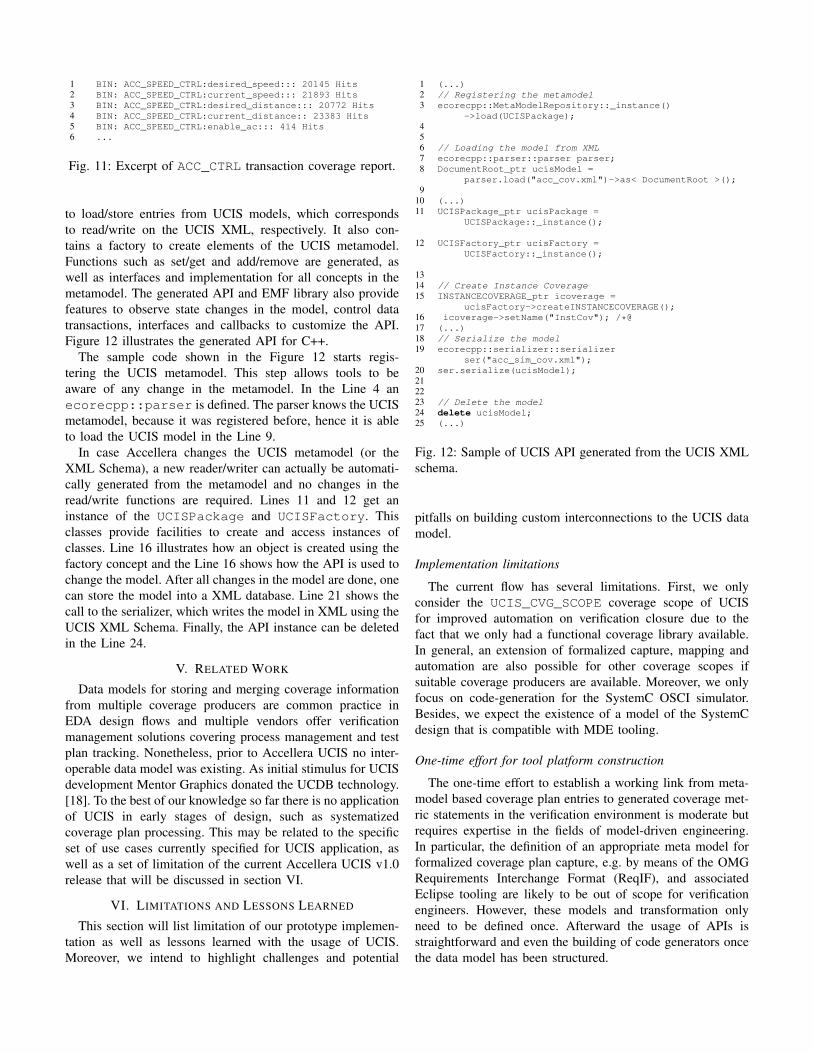
1 BIN: ACC_SPEED_CTRL:desired_speed::: 20145 Hits2 BIN: ACC_SPEED_CTRL:current_speed::: 21893 Hits3 BIN: ACC_SPEED_CTRL:desired_distance::: 20772 Hits4 BIN: ACC_SPEED_CTRL:current_distance:: 23383 Hits5 BIN: ACC_SPEED_CTRL:enable_ac::: 414 Hits6 ...
Fig. 11: Excerpt of ACC_CTRL transaction coverage report.
to load/store entries from UCIS models, which correspondsto read/write on the UCIS XML, respectively. It also con-tains a factory to create elements of the UCIS metamodel.Functions such as set/get and add/remove are generated, aswell as interfaces and implementation for all concepts in themetamodel. The generated API and EMF library also providefeatures to observe state changes in the model, control datatransactions, interfaces and callbacks to customize the API.Figure 12 illustrates the generated API for C++.
The sample code shown in the Figure 12 starts regis-tering the UCIS metamodel. This step allows tools to beaware of any change in the metamodel. In the Line 4 anecorecpp::parser is defined. The parser knows the UCISmetamodel, because it was registered before, hence it is ableto load the UCIS model in the Line 9.
In case Accellera changes the UCIS metamodel (or theXML Schema), a new reader/writer can actually be automati-cally generated from the metamodel and no changes in theread/write functions are required. Lines 11 and 12 get aninstance of the UCISPackage and UCISFactory. Thisclasses provide facilities to create and access instances ofclasses. Line 16 illustrates how an object is created using thefactory concept and the Line 16 shows how the API is used tochange the model. After all changes in the model are done, onecan store the model into a XML database. Line 21 shows thecall to the serializer, which writes the model in XML using theUCIS XML Schema. Finally, the API instance can be deletedin the Line 24.
V. RELATED WORK
Data models for storing and merging coverage informationfrom multiple coverage producers are common practice inEDA design flows and multiple vendors offer verificationmanagement solutions covering process management and testplan tracking. Nonetheless, prior to Accellera UCIS no inter-operable data model was existing. As initial stimulus for UCISdevelopment Mentor Graphics donated the UCDB technology.[18]. To the best of our knowledge so far there is no applicationof UCIS in early stages of design, such as systematizedcoverage plan processing. This may be related to the specificset of use cases currently specified for UCIS application, aswell as a set of limitation of the current Accellera UCIS v1.0release that will be discussed in section VI.
VI. LIMITATIONS AND LESSONS LEARNED
This section will list limitation of our prototype implemen-tation as well as lessons learned with the usage of UCIS.Moreover, we intend to highlight challenges and potential
1 (...)2 // Registering the metamodel3 ecorecpp::MetaModelRepository::_instance()
->load(UCISPackage);456 // Loading the model from XML7 ecorecpp::parser::parser parser;8 DocumentRoot_ptr ucisModel =
parser.load("acc_cov.xml")->as< DocumentRoot >();9
10 (...)11 UCISPackage_ptr ucisPackage =
UCISPackage::_instance();
12 UCISFactory_ptr ucisFactory =UCISFactory::_instance();
1314 // Create Instance Coverage15 INSTANCECOVERAGE_ptr icoverage =
ucisFactory->createINSTANCECOVERAGE();16 icoverage->setName("InstCov"); /*@17 (...)18 // Serialize the model19 ecorecpp::serializer::serializer
ser("acc_sim_cov.xml");20 ser.serialize(ucisModel);212223 // Delete the model24 delete ucisModel;25 (...)
Fig. 12: Sample of UCIS API generated from the UCIS XMLschema.
pitfalls on building custom interconnections to the UCIS datamodel.
Implementation limitations
The current flow has several limitations. First, we onlyconsider the UCIS_CVG_SCOPE coverage scope of UCISfor improved automation on verification closure due to thefact that we only had a functional coverage library available.In general, an extension of formalized capture, mapping andautomation are also possible for other coverage scopes ifsuitable coverage producers are available. Moreover, we onlyfocus on code-generation for the SystemC OSCI simulator.Besides, we expect the existence of a model of the SystemCdesign that is compatible with MDE tooling.
One-time effort for tool platform construction
The one-time effort to establish a working link from meta-model based coverage plan entries to generated coverage met-ric statements in the verification environment is moderate butrequires expertise in the fields of model-driven engineering.In particular, the definition of an appropriate meta model forformalized coverage plan capture, e.g. by means of the OMGRequirements Interchange Format (ReqIF), and associatedEclipse tooling are likely to be out of scope for verificationengineers. However, these models and transformation onlyneed to be defined once. Afterward the usage of APIs isstraightforward and even the building of code generators oncethe data model has been structured.
UCIS data model
From our point of view it is a promising direction thatthere is not only a common standardized data model forexchange and merge of coverage producers data, but alsoa more standardized way of processing the coverage planfrom higher levels of abstraction. Here, the current UCIS v1.0release is missing specific structures in the data model to allowfast adaption for testplan description such as generic triggerconditions for metrices, a mandatory information for code-generation for RTL design.
The experience from MDE community may contributes forthose issues. A domain-specific language can be specified toaddress the condition expressions at different abstraction levels(RTL/TLM), by using existing languages from EDA com-munity, such as SystemVerilog or defining a new expressionlanguage tailored to this problem.
UCIS schema and API
Despite the fact that the Accellera UCIS v1.0 standardrelease provides a header file describing the standardized APIfunctions, a reference reader (or writer) implementation is notincluded. Moreover, the standardized API functions do notalways match with the structure of the XML schema elements.Such a mismatch can be bothersome if no synchronizationmechanism is provided once the UCIS model and API evolve.
Metamodeling tools such as ECORE, EMF4CPP and MDEstandards can provide strong contributions to UCIS users suchas automatic code generation based on the UCIS metamodel.Such a generation can act as synchronization mechanismbetween API and data model. Moreover, additional featuressuch as model copy, merge, version control and others areavailable, once a metamodel is available.
VII. CONCLUSION
In this article we introduced an approach to systematizecoverage metric generation based on methodical coverage plandata capture and machining, utilizing the Unified CoverageInteroperability Standard (UCIS). We formalized the flow fromdesign specification to verification plan and coverage planspecification by means UCIS as intermediate format. Defininga verification methodology incorporating these UCIS relatedsteps in the earlier phases of verification planning we can assistand automize functional coverage metric generation. Despitethe fact that we concentrated on the UCIS_CVG_SCOPEfunctional coverage scope of UCIS, the approach in generalis also applicable to other coverage scopes of UCIS - ifsuitable coverage producers are available. Moreover, althoughknowledge of model-driven engineering techniques and spe-cific software centric tooling was necessary to define partsof the verification process steps, the actual end-user, here averification engineer, does not necessarily need to be awareof the back-end flows once an initial one-time effort setupwas conducted. Therefore, we see additional potential for theusage of standardized coverage models such as UCIS in earlierphases of the system design, in particular, the verificationplan creation and exploitation phase, besides being the future
standard for coverage data exchange between different vendortool chains and flows.
ACKNOWLEDGMENTS
This work was partly funded by the German Ministry of Ed-ucation and Research (BMBF) through the project SANITAS(16M3088I) [19], the DFG SFB 614, the ITEA2 projectsVERDE (01S09012) and TIMMO-2-USE (01IS10034). Wegreatly appreciate the cooperation with the project partners.
REFERENCES
[1] Accellera Organization, Inc. (2012, May) Universal VerificationMethodology (UVM). Accellera Organization, Inc. [Online]. Available:http://www.accellera.org/downloads/standards/uvm
[2] Accellera Organization, Inc. (2012, June) Unified CoverageInteroperability Standard (UCIS). Accellera Organization, Inc. [Online].Available: http://www.accellera.org/downloads/standards/ucis
[3] M. F. S. Oliveira, C. Kuznik, W. Mueller, W. Ecker, and V. Esen, “ASystemC Library for Advanced TLM Verification,” in Proceeding ofDesign and Verification Conference (DVCON), 2012.
[4] C. Kuznik and W. Muller, “Functional Coverage-driven Verification withSystemC on Multiple Level of Abstraction,” Proceeding of Design andVerification Conference (DVCON), 2011.
[5] M. F. Oliveira, C. Kuznik, H. M. Le, D. Groe, F. Haedicke, W. Mueller,R. Drechsler, W. Ecker, and V. Esen, “The System Verification Method-ology for Advanced TLM Verification,” ser. CODES+ISSS ’12.
[6] C. Kuznik and W. Muller, “Verification Closure of SystemC Designswith Functional Coverage,” 16th North American SystemC User GroupMeeting, 2011.
[7] Cadence Design Systems, Inc. Open Verification Methodology Multi-Language (OVM-ML). [Online]. Available: http://www.ovmworld.org/
[8] J. Bezivin, “On the unification power of models,” Software and SystemsModelling, vol. 4, no. 2, pp. 171–188, May 2005.
[9] D. Gasevic, D. Djuric, and V. Devedzic, Model Driven Engineering andOntology Development. Berlin, Heidelberg: Springer Berlin Heidelberg,2009. [Online]. Available: http://dx.doi.org/10.1007/978-3-642-00282-3
[10] R. France and B. Rumpe, “Model-driven Development of Complex Soft-ware: A Research Roadmap,” in 2007 Future of Software Engineering,ser. FOSE ’07. Washington, DC, USA: IEEE Computer Society, May2007, pp. 37–54.
[11] Questa SIM Users Manual, v10.1a, Chapter 25 Coverage andVerification Management in the UCDB. [Online]. Available: http://www.mentor.com/products/fv/questa-verification-platform
[12] K. Marquet, B. Karkare, and M. Moy, “A Theoretical and ExperimentalReview of SystemC Front-ends,” in FDL, A. Morawiec, J. Hinderscheit,A. Morawiec, and J. Hinderscheit, Eds. ECSI, Electronic Chips &Systems design Initiative, 2010, pp. 124–129.
[13] “IEEE Standard for IP-XACT, Standard Structure for Packaging, Inte-grating, and Reusing IP within Tools Flows,” IEEE Std 1685-2009, pp.C1 –360, 18 2010.
[14] W. Muller, A. Bol, A. Krupp, and O. Lundkvist, “Generation ofexecutable testbenches from natural language requirement specificationsfor embedded real-time systems,” in DIPES/BICC, 2010, pp. 78–89.
[15] Object Management Group. (2011, April) Requirements InterchangeFormat (ReqIF) v1.0.1. [Online]. Available: http://www.omg.org/spec/ReqIF/
[16] M. D. Del Fabro, J. Bezivin, F. Jouault, E. Breton, and G. Gueltas,“AMW: A Generic Model Weaver,” Proc. of the 1eres Journees surl’Ingenierie Dirigee par les Modeles, 2005.
[17] F. Haedicke, H. M. Le, D. Groe, and R. Drechsler, “CRAVE:An Advanced Constrained RAndom Verification Environment forSystemC,” in Proceedings of the International Symposium on System-on-Chip 2012. October 11-12, Tampere, Finland. IEEE, 2012.[Online]. Available: http://www.systemc-verification.org/
[18] W. Gude. Questa Verification Management TechTalk. MentorGraphics Inc. [Online]. Available: http://www.mentor.com/player/2008/vm techtalk/index.htm
[19] Collaborative verification along the entire value-added chain;”SANITAS” research project launched under management of Infineon.[Online]. Available: http://www.infineon.com/cms/en/corporate/press/news/releases/2009/INFXX200912-018.html