Embed Size (px)
Citation preview
Automated Testbench Generation for Communication Systems
by
Xin Qu
Thesis submitted to the faculty of the
Virginia Polytechnic Institute and State University
in partial fulfillment of the requirements for the degree of
Master of Science
in
Computer Engineering
APPROVED:
_________________________
Dr. F. G. Gray, Chairman
_________________________ _________________________
Dr. J. R. Armstrong Dr. S. F. Midkiff
November 2000
Blacksburg, Virginia
ii
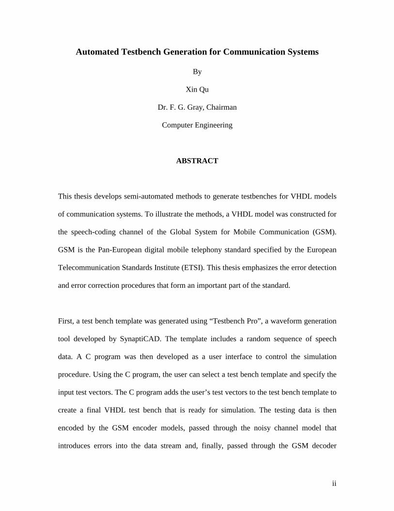
Automated Testbench Generation for Communication Systems
By
Xin Qu
Dr. F. G. Gray, Chairman
Computer Engineering
ABSTRACT
This thesis develops semi-automated methods to generate testbenches for VHDL models
of communication systems. To illustrate the methods, a VHDL model was constructed for
the speech-coding channel of the Global System for Mobile Communication (GSM).
GSM is the Pan-European digital mobile telephony standard specified by the European
Telecommunication Standards Institute (ETSI). This thesis emphasizes the error detection
and error correction procedures that form an important part of the standard.
First, a test bench template was generated using “Testbench Pro”, a waveform generation
tool developed by SynaptiCAD. The template includes a random sequence of speech
data. A C program was then developed as a user interface to control the simulation
procedure. Using the C program, the user can select a test bench template and specify the
input test vectors. The C program adds the user’s test vectors to the test bench template to
create a final VHDL test bench that is ready for simulation. The testing data is then
encoded by the GSM encoder models, passed through the noisy channel model that
introduces errors into the data stream and, finally, passed through the GSM decoder
iii
models which attempt to correct the channel errors. Sophisticated error detection and
error correction algorithms are used in the encoder/decoder models to increase the
reliability of data transmission over the noisy channel. Finally, the original speech data is
compared to the decoder output to detect any remaining bit errors and to evaluate the
system performance.
The simulation system is semi-automated. The user selects a set of parameters using the
C program interface. A testbench is then automatically created and simulated. Two final
report files are automatically generated. No user interaction is needed after the initial
parameter selection.
Several experiments were performed to illustrate the various features of the automated
testbench generation system.

To my parents

v
Acknowledgments
I would like to express my sincere thanks to Dr. F. G. Gray, my advisor, whose guidance
and encouragement is invaluable. It has been an honor and memorable experience
working with him for the past nearly 2 years.
I also would like to thank Dr. James R. Armstrong for his support and help on this
project, and thank him for serving as a member on my committee. I am grateful to Dr.
Scott F. Midkiff for being on my committee.
I thank my parents for standing behind me all the time and I thank my friends who made
my stay at Virginia Tech a great pleasure. I thank God for all his blessings.
I would like to thank the National Science Foundation for its support of this project.
vi
Table of Contents
Chapter 1. Introduction ....................................................................................................... 1
1.1 Motivation ........................................................................................................... 1
1.2 Task Description ................................................................................................. 2
1.3 Thesis Organization............................................................................................. 3
Chapter 2. Background........................................................................................................ 5
2.1 Overview of GSM ............................................................................................... 5
2.2 Overview of VHDL............................................................................................. 6
2.3 Overview of System Construction ...................................................................... 8
2.3.1 GSM Channel Encoding.............................................................................. 8
2.3.2 Test Data Generation Techniques ............................................................. 10
2.3.3 Channel Model .......................................................................................... 11
2.3.4 System Structure ....................................................................................... 11
Chapter 3. Implementation of Encoders............................................................................ 14
3.1 GSM frame Structure ........................................................................................ 14
3.2 Speech Coding in GSM..................................................................................... 18
3.3 Channel Coding in GSM................................................................................... 21
vii
3.4 GSM Parity Encoder ......................................................................................... 22
3.5 Convolutional Encoder...................................................................................... 24
3.6 Interleaver Encoder ........................................................................................... 28
3.7 Packet Format Encoder ..................................................................................... 31
3.7.1 Normal Burst ............................................................................................. 32
3.7.2 Random Access Burst ............................................................................... 34
3.7.3 Synchronization Burst ............................................................................... 36
3.8 Differential Encoder.......................................................................................... 37
3.9 Summary ........................................................................................................... 39
Chapter 4. Implementation of decoders ............................................................................ 40
4.1 Differential Decoder.......................................................................................... 40
4.2 Packet Format Decoder ..................................................................................... 41
4.3 Interleaver Decoder ........................................................................................... 42
4.4 Viterbi Decoder ................................................................................................. 45
4.5 Parity Check Decoder........................................................................................ 60
Chapter 5. Implementation of Channel Model.................................................................. 61
5.1 Background ....................................................................................................... 61
5.2 Channel Model Structure .................................................................................. 62
5.3 Channel Model Implementation........................................................................ 63
5.3.1 Random Error Mode.................................................................................. 63
5.3.2 Burst Error Mode ...................................................................................... 66
5.4 Channel Model Validation ................................................................................ 68
Chapter 6. Implementation of the User Interface.............................................................. 71
viii
6.1 Overview ........................................................................................................... 71
6.2 Approach ........................................................................................................... 72
6.3 Template Test bench Generation....................................................................... 72
6.3.1 Random Error Mode User Interface.......................................................... 77
6.3.2 Burst Error Mode User Interface............................................................... 80
6.4 Simulation Results of GSM Speech Coding System ........................................ 83
6.4.1 Random Error Mode.................................................................................. 86
6.4.2 Burst error mode........................................................................................ 87
Chapter 7. Smnnary........................................................................................................... 92
References ......................................................................................................................... 93
Appendix A: VHDL code for GSM encoder models........................................................ 95
Appendix B: VHDL code for GSM decoder models ...................................................... 112
Appendix C: VHDL code for channel models ................................................................ 139
Appendix D: Channel model validation log file ............................................................. 143
Appendix E: C code for control file and comparator ...................................................... 146
Appendix F: VHDL testbench template.......................................................................... 158
Vita .................................................................................................................................. 163
List of Illustrations
Figure 2.1. A typical test bench........................................................................................... 7
Figure 2.2. GSM channel coding structure. ...................................................................... 12
Figure 3.1. 26-frame multi-frame structure [9]. ................................................................ 15
Figure 3.2. 51-frame multi-frame [9]. ............................................................................... 16
Figure 3.3. GSM basic frame structure [9]........................................................................ 17
Figure 3.4. Speech data compression [10]. ....................................................................... 19
Figure 3.5. Parity Error detection method used for full rate encoder................................ 23
Figure 3.6. Linear feedback shift register in parity encoder. ............................................ 23
Figure 3.7. Convolutional error correction method used for RELP full rate encoder....... 25
Figure 3.8. Convolutional encoder for speech encoding [13]. .......................................... 26
Figure 3.9. Example of a convolutional encoder. ............................................................. 27
Figure 3.10. Details of interleaving process [13]. ............................................................. 29
Figure 3.11. Diagonal interleaving of speech data [14]. ................................................... 30
Figure 3.12. Structure of a normal burst. .......................................................................... 32
x
Figure 3.13. Structure of a random access burst. .............................................................. 35
Figure 3.14. Structure of a synchronization burst. ............................................................ 36
Figure 3.15. Burst structures in a GSM system................................................................. 37
Figure 3.16. Differential encoding. ................................................................................... 38
Figure 4.1. Differential decoding mapping format. .......................................................... 41
Figure 4.2. Diagonal interleaver decoding of speech data. .............................................. 43
Figure 4.3. Reordering scheme for a traffic channel TCH................................................ 44
Figure 4.4. Interleaver decoding algorithm....................................................................... 45
Figure 4.5. Encoder for a rate-1/2 convolutional code...................................................... 46
Figure 4.6. State diagram for the convolutional encoder in Figure 4.2............................. 48
Figure 4.7. Trellis diagram for the convolutional encoder in Figure 4.6. ......................... 49
Figure 4.8. Trellis diagram for the convolutional encoder in Figure 4.6 (continued)....... 50
Figure 4.9. Binary memoryless channel model................................................................. 52
Figure 4.10. Binary symmetric channel model. ................................................................ 52
Figure 4.11. Hard-decision Viterbi decoding (example)................................................... 57
Figure 4.12. Viterbi algorithm example. ........................................................................... 58
Figure 5.1. Structure of the channel model. ...................................................................... 62
Figure 5.2. Random error distribution............................................................................... 69
Figure 6.1. Clock signal details in Testbench Pro............................................................. 73
Figure 6.2. Speech data stream signal in Testbench Pro. .................................................. 74
Figure 6.3. Final timing diagram in Testbench Pro........................................................... 75
Figure 6.4. Channel input/output data stream in channel model....................................... 76
Figure 6.5 Random error channel simulation result .......................................................... 78
xi
Figure 6.6. Random error channel simulation log file. ..................................................... 80
Figure 6.7. Burst error channel model simulation result................................................... 82
Figure 6.8. Burst error channel mode simulation log file. ................................................ 83
Figure 6.9. GSM coding system simulation...................................................................... 84
Figure 6.10. Detail of the input speech data stream. ......................................................... 85
Figure 6.11. Detail of the output speech data stream. ....................................................... 85
Figure 6.12. Random error mode system simulation log file............................................ 86
Figure 6.13. Burst error mode system simulation log file................................................. 87
Figure 6.14. Simulation results of random error mode. .................................................... 88
Figure 6.15. Simulation results of random error mode continue. ..................................... 89
Figure 6.16. Simulation results of burst error mode. ........................................................ 90
1
Chapter 1. Introduction
Chapter 1 provides an introduction to the motivation and the background of this project
and the organization of this thesis.
1.1 Motivation
Digital communications systems require error detection and error correction coding to
achieve their full potential capacity. In the last two decades, coding techniques and
processing power evolved to the point where error correction coding is widely used in
communication systems. Global System for Mobile Communication (GSM) is one of the
most popular systems used in cellular telecommunications. GSM was developed as the
next-generation digital cellular mobile communication system for Europe in 1991. Since
then most European countries and Asian countries plus Australia have adopted the GSM
system. GSM uses several error detection and error correction techniques to make data
transfer more reliable.
2
Hardware description languages (HDLs) like the VHSIC (Very High Speed Integrated
Circuit) Hardware Description Language (VHDL) allow digital circuit designers to create
and simulate models at various levels of abstraction and to synthesize these models into
gate level form suitable for either field programmable gate arrays (FPGA) or application
specific integrated circuits (ASIC) implementation.
1.2 Task Description
As the complexity of systems increases, system-level models become increasingly
important. These models are critical because they frequently represent the first direct
interpretation of the specification. Thus, it is important to validate these models so that
the design process proceeds smoothly. Model validation consumes 60 to 70% of system
design effort [2]. Therefore, any improvement in verification efficiency is worth at least
twice as much as a similar improvement in design process efficiency. This thesis
primarily addresses validation issues.
The system models are typically coded in hardware description languages and, thus, can
form the input to a synthesis tool [1]. In this thesis, semi-automated methods are
developed to generate test benches for VHDL models of communication systems. GSM
speech coding models are developed as an example of a typical communication system.
The channel model is built to generate errors in order to simulate noise during data
transmission. The input data will be encoded by the GSM encoder models, the channel
model will introduce errors, and the GSM decoder models will attempt to correct the
errors. Finally, the original speech data will be compared to the output of the decoder
3
models to detect any remaining bit errors and to evaluate the error correction
performance of the system. All the models could be used for further research.
One basic approach used to generate test benches for the GSM system uses a software
package Testbench Pro which was developed by SynaptiCAD. Traditionally, the designer
needed to write test benches by hand and carefully set up the test data including the
timing and synchronization of data. Testbench Pro allows a designer to set up data types
and draw a timing diagram to create testbench input data streams. Some modifications
were needed to make the testbench work for the particular model, but it greatly simplifies
the procedure for creating a test bench, especially when a large amount of data is
involved.
1.3 Thesis Organization
The thesis contains an abstract, eight chapters, a bibliography and five appendices.
Chapter 1 of this thesis provides an introduction to the motivation and the background of
this project and the organization of this thesis.
Chapter 2 provides an overview of the GSM system, including error detection and error
correction algorithms used in the encoders and the decoders.
4
Chapter 3 describes the GSM frame structure and the implementation of the encoders.
There are five different encoders involved in GSM system encoding. The functions of
these encoders are error detection, error correction and data re-formatting.
Chapter 4 describes the five different decoders used for decoding the speech data. Each
decoder is paired with its corresponding encoder described in Chapter 3.
Chapter 5 discusses the details of implementation of the channel model that generates a
variety of noise and error statistics. The validation of the channel model is also included
in this chapter.
Chapter 6 provides the simulation results for the GSM system for various testing
examples. It describes the semi-automated techniques developed for generating test
benches for VHDL models of communication systems.
Chapter 7 states the conclusions drawn from the work done and discusses possible
avenues for future research
5
Chapter 2. Background
Chapter 2 provides an overview of the GSM system including overviews of the error
detection and error correction algorithms used in the encoders and the decoders.
Algorithm details are provided in Chapter 3 as part of the encoder descriptions.
2.1 Overview of GSM
Global System for Mobile communication GSM is a digital cellular communications
network that is used in over 120 countries all over the world. The first commercial GSM
telephones were introduced in 1991 and the its use has grown rapidly since then. In 1998,
there were over 100 million GSM phones in use and predictions show that there will be
over 300 million GSM phones by the year 2002. GSM represents an extraordinarily
successful strategy in the development of modern mobile communication systems.
6
The GSM network provides for mobile voice communication as well as many new
services such as mobile fax and text messaging. The complete GSM standards are openly
published and the technology is continually being improved. The GSM system offers the
following advantages: [3]
1. Superior speech quality
2. Low terminal, operational and service costs
3. A high level of security
4. International roaming
5. Support of low-power hand-portable terminals
6. A variety of new services and network facilities
As part of this thesis, VHDL behavioral models for GSM speech channel encoding and
decoding were built to provide an example of a commercial communication system.
These models were used to illustrate the testbench generation techniques developed for
the thesis.
2.2 Overview of VHDL
VHSIC Hardware Description Language (VHDL) is a computer language that is widely
used in modern digital circuit design. It was designed to model concurrent hardware
systems and is a powerful tool for simulating and synthesizing complex digital electronic
circuits.
7
A simulator supports the VHDL language. Thus, the model in an HDL description can be
simulated to validate a design. Prototyping of complicated systems is extremely
expensive, and the goal of those concerned with the development of hardware languages
is to replace this prototyping process by validation through simulation.
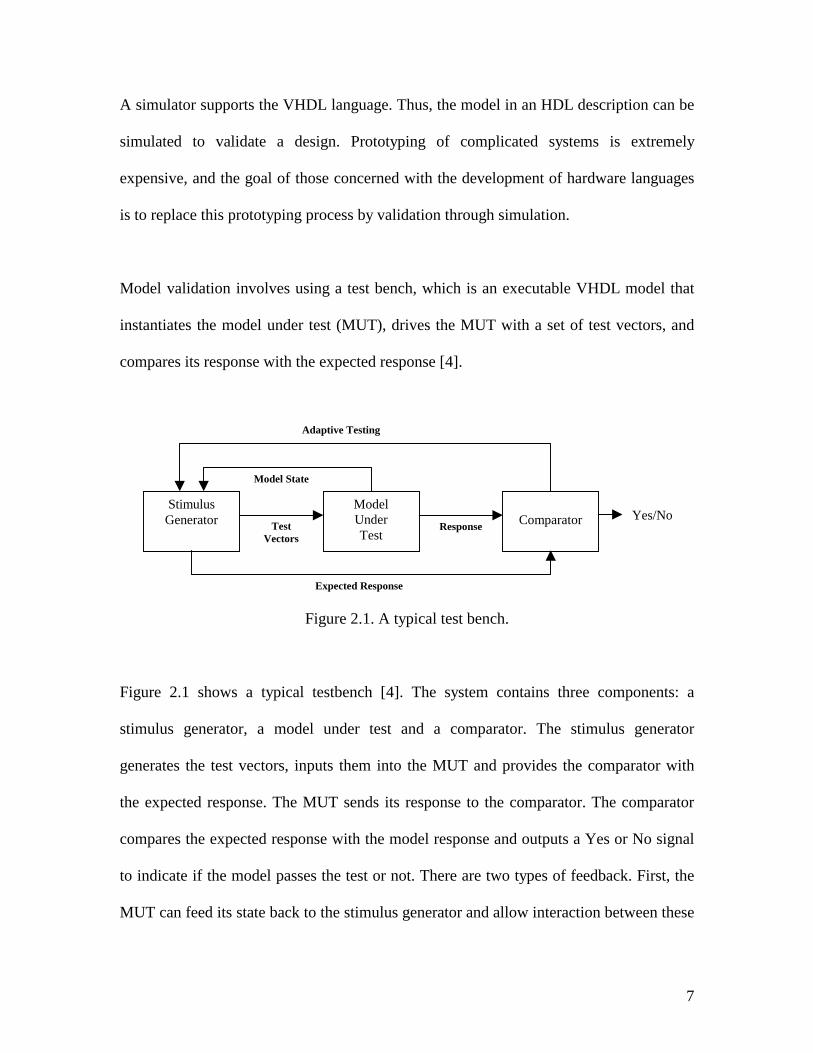
Model validation involves using a test bench, which is an executable VHDL model that
instantiates the model under test (MUT), drives the MUT with a set of test vectors, and
compares its response with the expected response [4].
Figure 2.1. A typical test bench.
Figure 2.1 shows a typical testbench [4]. The system contains three components: a
stimulus generator, a model under test and a comparator. The stimulus generator
generates the test vectors, inputs them into the MUT and provides the comparator with
the expected response. The MUT sends its response to the comparator. The comparator
compares the expected response with the model response and outputs a Yes or No signal
to indicate if the model passes the test or not. There are two types of feedback. First, the
MUT can feed its state back to the stimulus generator and allow interaction between these
Stimulus Generator
Model Under Test
Comparator Test
Vectors Response
Model State
Adaptive Testing
Expected Response
Yes/No
8
two components. Second, the comparator signals can be fed back to the stimulus
generator to allow adaptive testing [5, 6].
2.3 Overview of System Construction
This section describes the major building blocks of a GSM communication coding
system.
2.3.1 GSM Channel Encoding
Channel encoding is a process by which one or more control and data signals are
combined with error detection or error correction information. After a digital speech
source produces a sequence of digital bits, the encoder adds redundant bits that allow
error detection and/or error correction at the receiver. In general, a communication
system requires a decoding process at the receiving end that is the inverse of the encoding
process to restore the original data. The decoder will either correct the errors, if possible,
or report the errors if they cannot be corrected. The testing data that is applied in this
communication system is a sequence of 0s and 1s. There are 260 bits of data in one GSM
speech data frame.
There are three basic types of error protection coding used in the GSM system: cyclic
redundancy check (CRC) codes, block codes, and convolutional codes.
9
A cyclic redundancy check (CRC) code [7] is an error detection method that is used to
determine if a series of data bits are received correctly during transmission. The added
data bits, called the CRC “check sum,” are generated from the original bits of data by a
specific mathematical equation. At the receiver side, the decoder follows the same
equation to recalculate the “check sum” bits and compares these with the received “check
sum” bits. If the recalculated check sum does not match the received check sum, an error
is detected. The details are discussed in Section 3.4. In GSM, CRC codes are used for all
call processing messages. CRC codes are also applied to some of the most significant bit
positions of the speech data.
A block code is an error detection parity code that is used in GSM for call processing
messages. The GSM system uses a special type of block code called a Fire code (named
after its inventor, mathematician Emanuel Fire) [8]. A block code is generated by
computing the sum of products of a fixed size block of binary bits. The Fire code is
referred to as a parity code but it is much more complex and sophisticated than a parity
check code. A parity check code is used to confirm if there is an even or odd number of
binary 1s in a block of data. A Fire code can detect and correct burst errors. This coding
method is used in the parity encoder and parity check decoder.
Convolutional coding is an error correction process that uses the input data to create a
continuous flow of bits protected from errors. As these bits go through the convolutional
encoder, an increased number of bits are produced. Convolutional coding is often used in
transmission systems that experience burst errors, such as cellular radio systems. In the
10
GSM system, convolutional codes are used for all types of digital signals, often in
combination with the CRC or block codes. Specific details are in Section 3.5.
2.3.2 Test Data Generation Techniques
A semi-automated testbench generation approach is developed to reduce the labor of
testbench creation. Specifically, the approach allows the user to control and modify the
value of the variables in the testbench without knowing the syntax and the structure of
VHDL.
First, the software Testbench Pro developed by SynaptiCAD, is used to create the clock
signals and the random data stream using the input and output port signals. Testbench Pro
provides a graphical user interface to add clock signals and/or input/output signals into
the testbench; the user only needs to make a slight modification to the automatically
generated testbench in the simulation procedure. The modification includes adding the
components and signal declarations at the beginning of the testbench file. For example,
for the GSM communication system, the declarations of different encoder and decoder
components and signals need to be added to the testbench to make a template testbench
for further use.
Second, in order to exchange information and collect input variables from users for each
simulation, a C program was developed to control the simulation process. The users will
be asked to specify which template testbench file should be used in the simulation and
which testing mode, such as “Random error” mode or “Burst error” mode to use. For the
11
“Random error” mode, the user will be asked for error probability and error duration
range; for the “Burst error” mode, the user will need to specify the error starting time and
the error duration. Also a “Seed” needs to be entered by the user for “Random error”
mode. Then, the control program will modify the selected testbench file according to the
values of all the variables input by the user to produce a final testbench that is ready for
simulation. Finally, the user will be asked how many times the simulation should be
repeated. The control program will then run the requested number of simulations and
generate two final report files that summarize the system performance. Details of the
control program are in Chapter 6.
2.3.3 Channel Model
The most important service offered to the user of cellular mobile networks is speech
transmission. The general technical requirement is to transmit voice signals at an
acceptable level of quality.
A channel model was developed for simulating channel noise between transmitter and
receiver by adding errors into the transmitted data. The details of the channel model are
included in Chapter 5.
2.3.4 System Structure
The GSM speech channel coding system structure diagram is shown below:
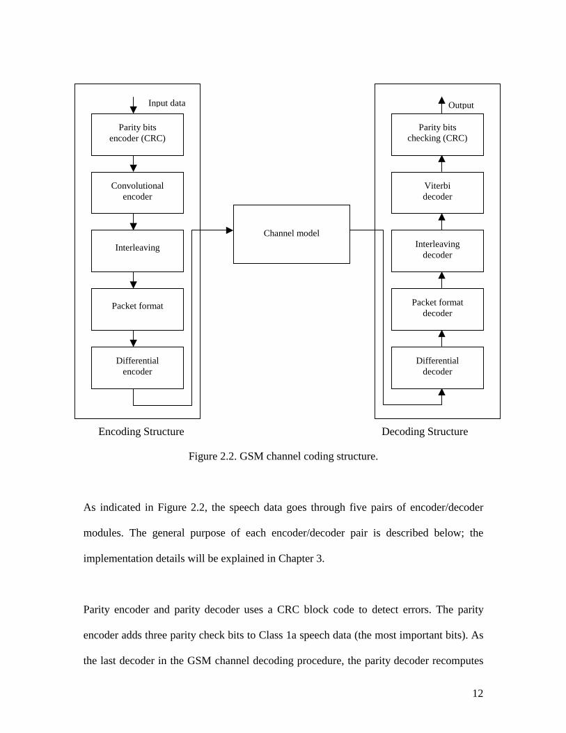
Figure 2.2. GSM channel coding structure.
As indicated in Figure 2.2, the speech data goes through five pairs of e
modules. The general purpose of each encoder/decoder pair is describ
implementation details will be explained in Chapter 3.
Parity encoder and parity decoder uses a CRC block code to detect err
encoder adds three parity check bits to Class 1a speech data (the most imp
the last decoder in the GSM channel decoding procedure, the parity deco
Parity bits encoder (CRC)
Convolutional encoder
Interleaving
Packet format
Differential encoder
Channel model
ch
P
Encoding Structure Decodi
Parity bits ecking (CRC)
Input data
ncoder
ed be
ors. T
ortant
der rec
acket fodecod
Interleadecod
Viterdecod
Differendecod
ng Stru
Output
12
/decoder
low; the
he parity
bits). As
omputes
rmat er
ving er
bi er
tial er
cture
13
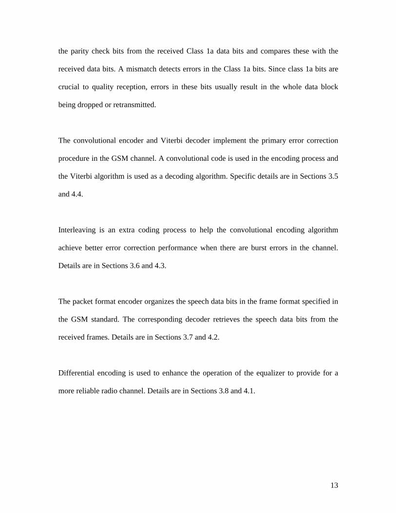
the parity check bits from the received Class 1a data bits and compares these with the
received data bits. A mismatch detects errors in the Class 1a bits. Since class 1a bits are
crucial to quality reception, errors in these bits usually result in the whole data block
being dropped or retransmitted.
The convolutional encoder and Viterbi decoder implement the primary error correction
procedure in the GSM channel. A convolutional code is used in the encoding process and
the Viterbi algorithm is used as a decoding algorithm. Specific details are in Sections 3.5
and 4.4.
Interleaving is an extra coding process to help the convolutional encoding algorithm
achieve better error correction performance when there are burst errors in the channel.
Details are in Sections 3.6 and 4.3.
The packet format encoder organizes the speech data bits in the frame format specified in
the GSM standard. The corresponding decoder retrieves the speech data bits from the
received frames. Details are in Sections 3.7 and 4.2.
Differential encoding is used to enhance the operation of the equalizer to provide for a
more reliable radio channel. Details are in Sections 3.8 and 4.1.
14
Chapter 3. Implementation of Encoders
Chapter 3 describes the GSM frame structure and the implementation of the encoders.
There are five different encoders involved in the GSM system encoding process. The
functions of these encoders are error detection, error correction and data re-formatting.
3.1 GSM frame Structure
The basic GSM frame is composed of eight 577-microsecond time slots that form a frame
with a duration of approximately 4.615 msec. The time slots within a frame are labeled
from 0 to 7. In Figure 3.1, the time slots are shown wrapped around a coil. A typical
GSM service assigns a user to one time slot per frame. This same numbered time slot is
used in consecutive frames to allow continuous communication.
15
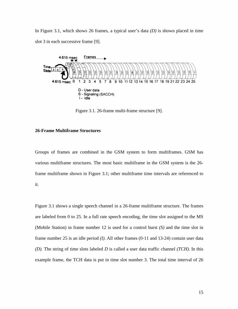
In Figure 3.1, which shows 26 frames, a typical user’s data (D) is shown placed in time
slot 3 in each successive frame [9].
Figure 3.1. 26-frame multi-frame structure [9].
26-Frame Multiframe Structures
Groups of frames are combined in the GSM system to form multiframes. GSM has
various multiframe structures. The most basic multiframe in the GSM system is the 26-
frame multiframe shown in Figure 3.1; other multiframe time intervals are referenced to
it.
Figure 3.1 shows a single speech channel in a 26-frame multiframe structure. The frames
are labeled from 0 to 25. In a full rate speech encoding, the time slot assigned to the MS
(Mobile Station) in frame number 12 is used for a control burst (S) and the time slot in
frame number 25 is an idle period (I). All other frames (0-11 and 13-24) contain user data
(D). The string of time slots labeled D is called a user data traffic channel (TCH). In this
example frame, the TCH data is put in time slot number 3. The total time interval of 26
16
frames is 26 x 4.615 milliseconds = 120 milliseconds. The other 7-time slots could be
used for additional user voice traffic in the same way as time slot number 3.
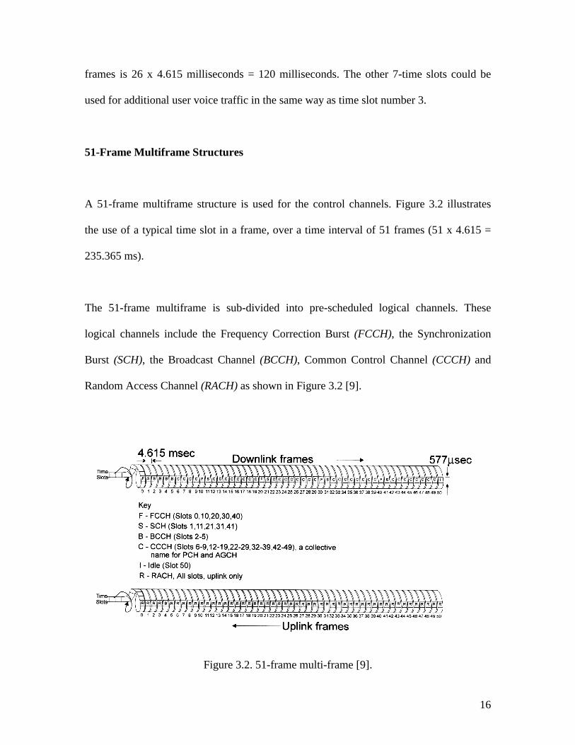
51-Frame Multiframe Structures
A 51-frame multiframe structure is used for the control channels. Figure 3.2 illustrates
the use of a typical time slot in a frame, over a time interval of 51 frames (51 x 4.615 =
235.365 ms).
The 51-frame multiframe is sub-divided into pre-scheduled logical channels. These
logical channels include the Frequency Correction Burst (FCCH), the Synchronization
Burst (SCH), the Broadcast Channel (BCCH), Common Control Channel (CCCH) and
Random Access Channel (RACH) as shown in Figure 3.2 [9].
Figure 3.2. 51-frame multi-frame [9].
17
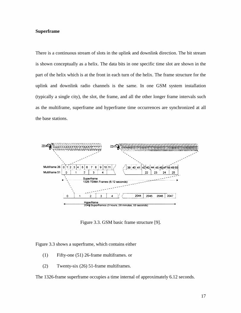
Superframe
There is a continuous stream of slots in the uplink and downlink direction. The bit stream
is shown conceptually as a helix. The data bits in one specific time slot are shown in the
part of the helix which is at the front in each turn of the helix. The frame structure for the
uplink and downlink radio channels is the same. In one GSM system installation
(typically a single city), the slot, the frame, and all the other longer frame intervals such
as the multiframe, superframe and hyperframe time occurrences are synchronized at all
the base stations.
Figure 3.3. GSM basic frame structure [9].
Figure 3.3 shows a superframe, which contains either
(1) Fifty-one (51) 26-frame multiframes. or
(2) Twenty-six (26) 51-frame multiframes.
The 1326-frame superframe occupies a time internal of approximately 6.12 seconds.
18
Hyperframe
The largest frame structure in the GSM system is the hyperframe which is composed of
2048 superframes (approximately 3½ hours). Figure 3.3 shows the structure of a
hyperframe.
3.2 Speech Coding in GSM
Speech coding is the process of characterizing and compressing digital signals where the
data compression process is optimized for speech or audio signals. The common word for
a speech coding devices is “codec” (coder/decoder).
One of the greatest concerns in any digital voice transmission system is the performance
of the speech codec. If the speech codec can’t accurately encode and decode speech
signals, channel noise will cause bit errors that result in distorted speech noticeable to the
user. The performance of the digital GSM speech codec is superior to an analog cellular
phone when radio conditions are poor. In addition, the mathematical operation used in the
GSM codec is completely standardized in every detail, and it is identical in each phone
and system. This uniformity eliminates the need for compatibility testing of different
manufacturers’ products.
19
Full Rate Speech Coding
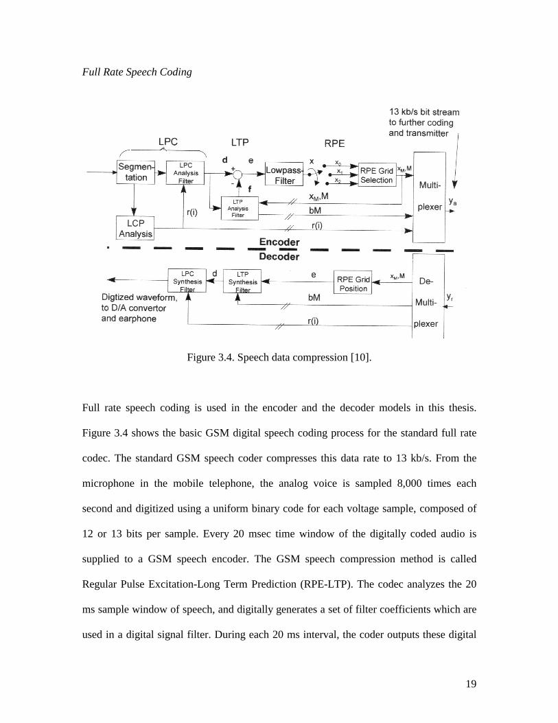
Figure 3.4. Speech data compression [10].
Full rate speech coding is used in the encoder and the decoder models in this thesis.
Figure 3.4 shows the basic GSM digital speech coding process for the standard full rate
codec. The standard GSM speech coder compresses this data rate to 13 kb/s. From the
microphone in the mobile telephone, the analog voice is sampled 8,000 times each
second and digitized using a uniform binary code for each voltage sample, composed of
12 or 13 bits per sample. Every 20 msec time window of the digitally coded audio is
supplied to a GSM speech encoder. The GSM speech compression method is called
Regular Pulse Excitation-Long Term Prediction (RPE-LTP). The codec analyzes the 20
ms sample window of speech, and digitally generates a set of filter coefficients which are
used in a digital signal filter. During each 20 ms interval, the coder outputs these digital
20
coefficients, the loudness value, and the pitch period (show in Figure 3.4). The effective
speech data rate before the encoding process is 13 kb/s.
To protect the speech data during the transmission, error protection bits are added to the
important information in the digitally coded signal which increases the bit rate to 22.8
kb/s. The 22.8 kb/s error protected data is interleaved over 8 adjacent slot periods. At the
receiver end, the data from these 8 bursts will be put back together to make up the
digitally coded signal of the 20 msec time window of speech (shown in Figure 3.4). The
decoder then processes the digital data stream to generate an analog sound waveform for
the ear to hear.
Basic speech is sensed by the channel encoder for each 20 ms segment and generates 260
bits at the output (shown in Figure 3.4). Thus the encoder output data rate is 13 kb/s.
After adding the redundant bits, the channel encoder releases 456 bits (22.8 kb/s). The
speech blocks are grouped into three error sensitivity classes depending on their
importance to the intelligibility of the speech [11].
• = Class 1a: three parity bits are derived from the first 50 Class 1a bits. Class 1a bits
are the most important bits in the 20 ms segment and are protected by multi error
protection coding. Therefore, the speech decoder is able to detect uncorrectable
errors within the Class 1a bits. If there are uncorrectable Class 1a bit errors, the
whole block is usually ignored.
21
• = Class 1b: the 132 Class 1b bits together with the 53 Class 1a bits (50 Class 1a bits
plus 3 parity bits) are encoded using a convolutional encoder. After adding four
tail bits, an r=1/2, K=5 convolutional code provides an output of 378 bits.
• = Class 2: The 78 least important bits are not protected.
The total number of bits generated by the encoder is 456 (378+78) bits.
3.3 Channel Coding in GSM
A major feature of digital data transmission is the myriad techniques used to protect data
or speech through coding. Coding adds additional bits to the original payload to provide
protection for the information. This gives the data more reliability and security since it is
possible to identify and even correct errors.
Coding consists of adding to the source data some redundant information calculated from
the source information. Decoding makes use of this redundancy to detect the presence of
errors or to estimate the most probable transmitted bits given those received. Errors are
detected when the calculated result from the received data is different from the
transmitted redundant bits.
Error detection coding is the process of sending additional data bits along with
transmitted data bits that can be used to determine if some or all of the bits have been
successfully received without error. Error correction coding is a process of using some
data bits that are transmitted along with the data message to help correct bits that are
22
received in error due to distorted radio transmission. Error correction is made possible by
sending bits that have a relationship to the data that is contained in the desired data block
or message. Coding is the mathematical relationship between the extra bits and the
original data that has been protected.
Various kinds of error protection coding are used in digital communication systems. All
error detection or error correction coding requires adding additional bits into the original
data stream and increases the total length of the transmitted data.
3.4 GSM Parity Encoder
In a block code, data is organized into fixed length blocks. Each block has k information
bits, which can represent any one of 2k distinct messages. The encoder adds (n-k) bits to
form a block n-bits long. These (n-k) additional bits are known as redundant bits, parity
bits, or check bits and carry no information. The check bits in the code block are
dependent on the information bits in the block.
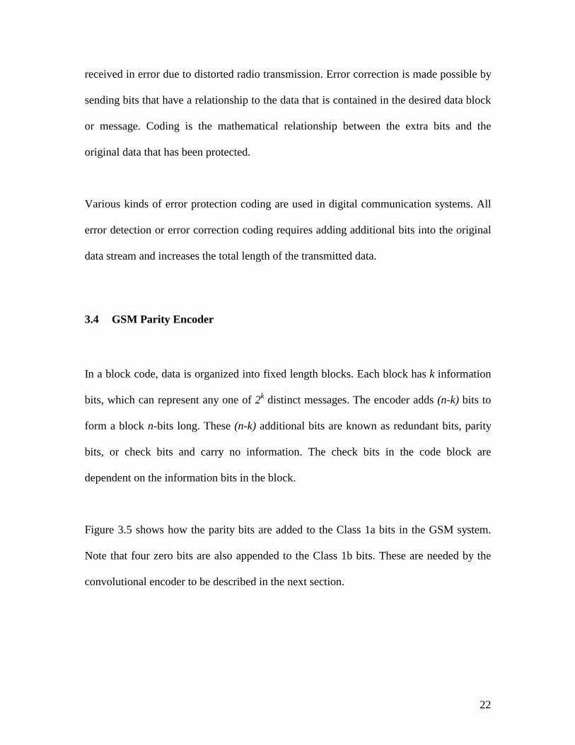
Figure 3.5 shows how the parity bits are added to the Class 1a bits in the GSM system.
Note that four zero bits are also appended to the Class 1b bits. These are needed by the
convolutional encoder to be described in the next section.
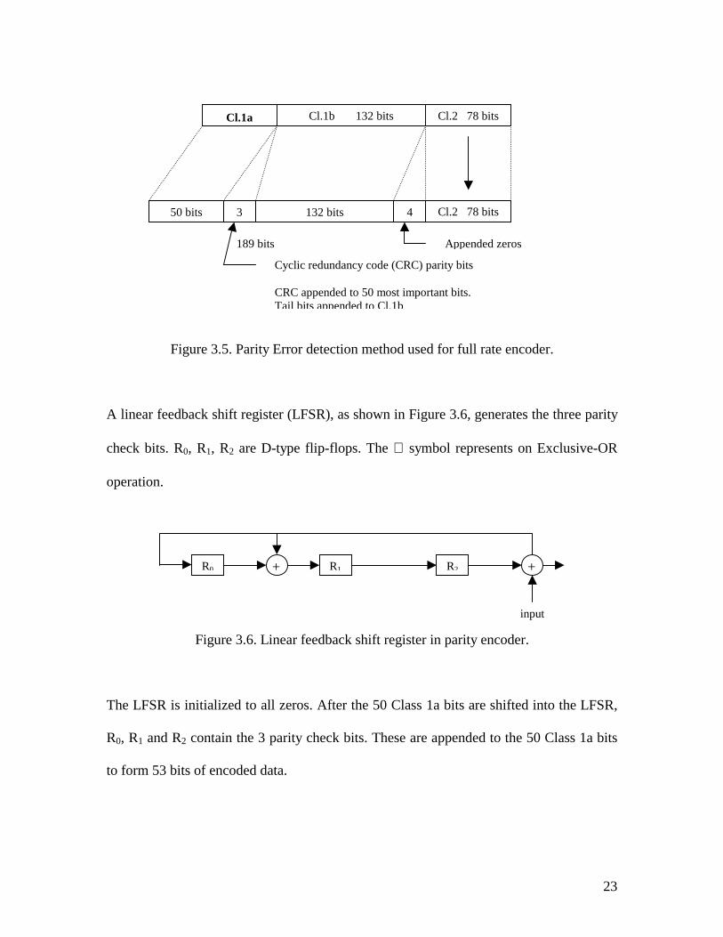
Figure 3.5. Parity Error detection method used
A linear feedback shift register (LFSR), as shown in Figu
check bits. R0, R1, R2 are D-type flip-flops. The ⊕ sym
operation.
Figure 3.6. Linear feedback shift register i
The LFSR is initialized to all zeros. After the 50 Class 1
R0, R1 and R2 contain the 3 parity check bits. These are
to form 53 bits of encoded data.
0 1
Cl.2 78 bits
Cl.1b 132 bits50 bits
3s
189 bits4
132 bits Cl.2 78 bitsCyclic redundancy code (CRC) parity bits CRC appended to 50 most important bits. Tail bits appended to Cl.1b
f
r
b
n
a
a
Appended zero
Cl.1a
or full rate encoder.
e 3.6, generates the three parity
ol represents on Exclusive-OR
2
R R R +parity encoder
bits are shifted
ppended to the
i
+
23
.
into the LFSR,
50 Class 1a bits
nput
24
At the receiver, the 50 received Class 1a bits are shifted into an identical LFSR. If the
contents of the receiver LFSR do not match the 3 received parity check bits, an error is
detected. Since these are the critical bits, the block is ignored if an error is detected.
3.5 Convolutional Encoder
A convolutional encoder typically will generate two or three output bits for each input
bit. The output bits generated by the encoder are dependent on the current input bit, as
well as the state of the encoder. The state of the encoder is represented by several bits
which precede the current bit. If the state of the encoder consists of the three previous
bits, then there are eight possible encoder states, one for each possible combination. This
encoder is said to have a constraint length K = 4 since the output depends on four bits
(the current bit plus three previous bits). The code rate r is defined as the number of input
bits divided by the number of output bits. Thus, an encoder which produces two output
bits for every input bit is said to have rate r = ½.
Convolutional coding adds redundant bits in such a way that the decoder can, within
limits, detect errors and correct them. This code is applied to both the class 1b bits and
class 1a bits (including the parity bits generated by the parity encoder) as shown in Figure
3.7. The convolutional code in a GSM system uses a rate of r = ½ and K = 5, which mean
that five consecutive bits are used to calculate the redundant bits and that for each data bit
an additional redundant bit is added. Before the information bits are encoded, four bits
are added at the end of the information bits. These bits are all set to zero and are used to
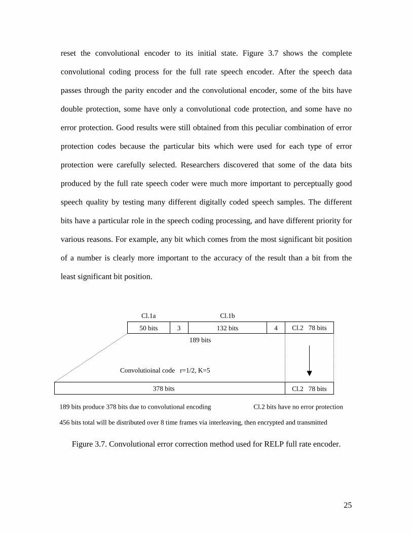
reset the convolutional encoder to its initial state. Figure 3.7 shows the complete
convolutional coding process for the full rate speech encoder. After the speech data
passes through the parity encoder and the convolutional encoder, some of the bits have
double protection, some have only a convolutional code protection, and some have no
error protection. Good results were still obtained from this peculiar combination of error
protection codes because the particular bits which were used for each type of error
protection were carefully selected. Researchers discovered that some of the data bits
produced by the full rate speech coder were much more important to perceptually good
speech quality by testing many different digitally coded speech samples. The different
bits have a particular role in the speech coding processing, and have different priority for
various reasons. For example, any bit which comes from the most significant bit position
of a number is clearly more important to the accuracy of the result than a bit from the
least significant bit position.
Figure 3.7. Convolu
189 bits produce 378 bits du 456 bits total will be distribu
50 bits
tional error
e to convoluti
ted over 8 tim
3
correction m
onal encoding
e frames via in
132 bits
ethod used for RE
Cl.2 b
terleaving, then encry
4
LP f
its have
pted a
Cl.2 78 bits
Cl.1a
Cl.1b Cl.2 78 bits 378 bitsConvolutioinal code r=1/2, K=5
189 bits
25
ull rate encoder.
no error protection
nd transmitted
The least important Class 2 bits are not protected at all during the convolutional coding
process. The 189 bits (Class 1a with parity bits and Class 1b) enter the convolutional
encoder, and 2 x 189 = 378 bits emerge; the 78 Class 2 bits are appended after the 378
coded bits to yield a total of 456 bits. This is exactly 4 times 114; and 114 is the number
of coded bits within one burst. This is also 8 times 57, which is the number of bits in
eight subblocks.
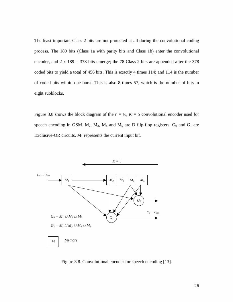
Figure 3.8 shows the block diagram of the r = ½, K = 5 convolutional encoder used for
speech encoding in GSM. M2, M3, M4 and M5 are D flip-flop registers. G0 and G1 are
Exclusive-OR circuits. M1 represents the current input bit.
Figure 3.8. Convolutional e
M1 MU0 … U188
GG0 = M1 ⊕ M4 ⊕ M5 G1 = M1 ⊕ M2 ⊕ M4 ⊕ M5
M
K = 5
2 M5M4M3
G0
1
C0 … C377
Memory
26
ncoder for speech encoding [13].
27
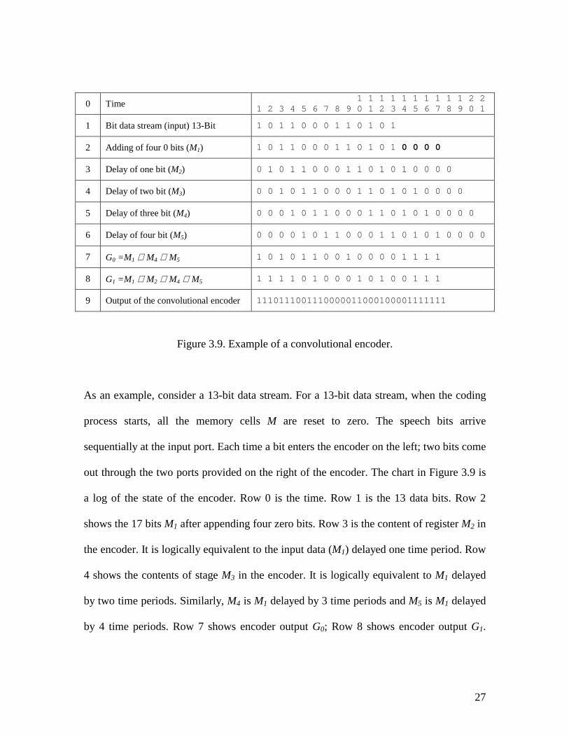
0 Time 1 1 1 1 1 1 1 1 1 1 2 21 2 3 4 5 6 7 8 9 0 1 2 3 4 5 6 7 8 9 0 1
1 Bit data stream (input) 13-Bit 1 0 1 1 0 0 0 1 1 0 1 0 1
2 Adding of four 0 bits (M1) 1 0 1 1 0 0 0 1 1 0 1 0 1 0 0 0 0
3 Delay of one bit (M2) 0 1 0 1 1 0 0 0 1 1 0 1 0 1 0 0 0 0
4 Delay of two bit (M3) 0 0 1 0 1 1 0 0 0 1 1 0 1 0 1 0 0 0 0
5 Delay of three bit (M4) 0 0 0 1 0 1 1 0 0 0 1 1 0 1 0 1 0 0 0 0
6 Delay of four bit (M5) 0 0 0 0 1 0 1 1 0 0 0 1 1 0 1 0 1 0 0 0 0
7 G0 =M1 ⊕ M4 ⊕ M5 1 0 1 0 1 1 0 0 1 0 0 0 0 1 1 1 1
8 G1 =M1 ⊕ M2 ⊕ M4 ⊕ M5 1 1 1 1 0 1 0 0 0 1 0 1 0 0 1 1 1
9 Output of the convolutional encoder 1110111001110000011000100001111111
Figure 3.9. Example of a convolutional encoder.
As an example, consider a 13-bit data stream. For a 13-bit data stream, when the coding
process starts, all the memory cells M are reset to zero. The speech bits arrive
sequentially at the input port. Each time a bit enters the encoder on the left; two bits come
out through the two ports provided on the right of the encoder. The chart in Figure 3.9 is
a log of the state of the encoder. Row 0 is the time. Row 1 is the 13 data bits. Row 2
shows the 17 bits M1 after appending four zero bits. Row 3 is the content of register M2 in
the encoder. It is logically equivalent to the input data (M1) delayed one time period. Row
4 shows the contents of stage M3 in the encoder. It is logically equivalent to M1 delayed
by two time periods. Similarly, M4 is M1 delayed by 3 time periods and M5 is M1 delayed
by 4 time periods. Row 7 shows encoder output G0; Row 8 shows encoder output G1.
28
Row 9 shows the output pair (G1 G0) at each time period. Recall that the (r=1/2) encoder
produces two output bits for each input bit.
In general, the performance of a convolutional encoder will improve as the constraint
length increases, or as the code rate decreases. Extensive tables are available which
tabulate the best convolutional codes for a given rate and constraint length [12]. These
codes are described by generator polynomials which describe relationships between the
current input and state bits, and the resulting output bits. Using these polynomials, a
convolutional encoder similar to the one in Figure 3.8 may be implemented.
3.6 Interleaver Encoder
In real life, bit errors often occur in bursts due to the fact that linear-fading dips affect
several consecutive bits [13]. Unfortunately, the GSM channel-coding techniques
discussed so far are most effective in detecting and correcting single random errors and
are not effective when errors occur in bursts. Interleaving is the reordering of data
coming out of a convolutional encoder prior to transmission so that consecutive bits of
data are distributed over a larger sequence of data to reduce the effect of burst errors. The
use of interleaving greatly increases the ability of error protection codes to correct for
burst errors. Many of the error protection coding processes can correct for small numbers
of consecutive errors, but cannot correct for errors that occur in longer consecutive
positions. On the downside, interleaving increases processing time and introduces an
additional encoding and decoding time delay. Some logical channels cannot use
29
interleaving because all of their data is transmitted in one short burst, and there is no
second burst or time slot with which to interleave.
It is fortunate that 456 bits will fit perfectly into four 114-bit time slots (sub-blocks), but
if these coded data were inserted into four consecutive sub-blocks, then the whole speech
block would be susceptible to a burst error. To reduce the effects of burst errors, these
data are spread out over eight sub-blocks in sub-blocks of 57 bits each.
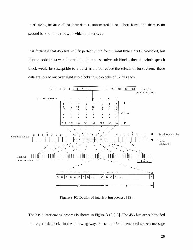
Figure 3.10. Details of interleaving process [13].
The basic interleaving process is shown in Figure 3.10 [13]. The 456 bits are subdivided
into eight sub-blocks in the following way. First, the 456-bit encoded speech message
Data sub blocks
Channel Frame number
Sub-block number 57-bit sub blocks
block is read into an 8-column by 57-row matrix RAM, filling each row in turn. The bits
are then read out of the RAM by column, forming eight sub-blocks of 57 bits each.
Adjacent bits in the original code word are thus placed into different sub-blocks
numbered 0 through 7 to correspond to the column number from which each block was
constructed.
Using a technique called diagonal interleaving, the eight 57-bit sub-blocks (block B in
Figure 3.10) are further interleaved with the sub-blocks from the preceding 456-bit
message block (block A in Figure 3.10) and the following 456-bit message block (Block
C in Figure 3.10) [14].
Figure 3.11. Diagonal interleaving of speech data [14].
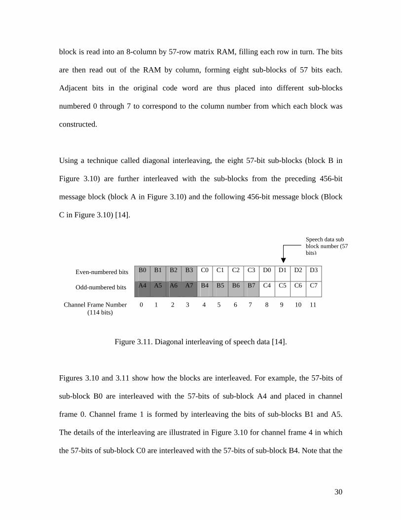
Figures 3.10 and 3.11 show how the blocks are interleaved. For example, th
sub-block B0 are interleaved with the 57-bits of sub-block A4 and placed
frame 0. Channel frame 1 is formed by interleaving the bits of sub-blocks
The details of the interleaving are illustrated in Figure 3.10 for channel fram
the 57-bits of sub-block C0 are interleaved with the 57-bits of sub-block B4.
B0 B1 B2 B3 C0 C1 C2 C3 D0 D1 D2
A4 A5 A6 A7 B4 B5 B6 B7 C4 C5 C6
Even-numbered bits Odd-numbered bits
Channel Frame Number 0 1 2 3 4 5 6 7 8 9 10 (114 bits)
Speech data sub block number (57 bits)
30
e 57-bits of
in channel
B1 and A5.
e 4 in which
Note that the
D3
C7
11
31
bits from sub-block C0 alternate with the bits from sub-block B4. The bits from C0 go
into the even-numbered bit positions in channel burst 4 and the bits from B4 go into the
odd numbered positions. Figure 3.11 shows which bits from each sub-block of B go into
even-numbered or odd-numbered positions of channel frame 0 through 7.
The final result is a continuous sequence of 114-bit channel frames each divided into two
57-bit sub-sequences as illustrated in Figure 3.10. This stream of channel frames is
passed through a packet format encoder prior to transmission.
This whole procedure of putting the bits into sub-blocks is referred to as reordering and
restructuring, and the mapping of the sub-blocks onto the eight channel frames is called
diagonal interleaving of sub-blocks [15].
3.7 Packet Format Encoder
The function of the packet format encoder is to reformat the coded speech data into the
standard GSM transmission format and to fit the data into time slots.
Due to the physical aspects of transmission, such as the RF channel schemes, access
techniques, power control, and timing considerations, the information is transmitted as
data (ones and zeros) confined to time slots with eight time slots in a frame. There are
147 total bits allotted in each time slot for data transmissions. Actually, there are 148 bit
times in each time slot, but the time for the first and last half bits are reserved for the on-
off RF switching time. There are three basic burst structures [16], the normal burst, the
random access burst, and the synchronization burst.
3.7.1 Normal Burst
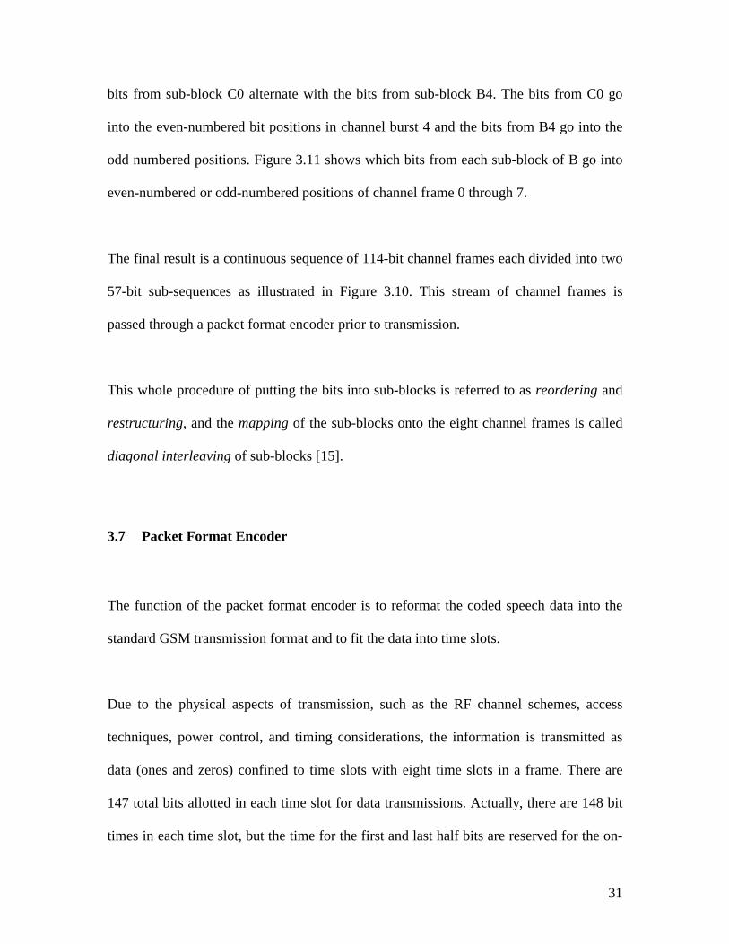
Figure 3.12 shows the structure of a normal burst. A normal burst carries almost anything
except special freight and it is the most common burst in the GSM system. A normal
burst is transmitted in one time slot either from the base station or from the mobile
station. There are eight time slots in a TDMA frame. The actual user data (speech data)
occupy only a portion of the time slots and the remainder of the bits are reserved for a
host of control functions and some demodulating aids.
Figure 3.12
Tail Bits (T). This small group con
each burst and is used as guard tim
during the ramping up and down of
T 3
Type Number of bits
Coded Data 57
S1
Training Sequence 26
S1
Coded Data 57
T 3
GP 8.25
148 Bit * 3.69us/bit = 546.12 us
32
. Structure of a normal burst.
sists of three bits at the beginning and at the end of
e. The tail bit time covers the periods of uncertainty
the power bursts from the mobile in accordance with
33
the power-versus-time template. The tail bits are always set to zero. Coincidentally, the
demodulation process requires some initial zero bit values.
Coded Data. A normal burst includes two sequences of 57 encoded data bits. This
corresponds to the interleaved bits described in the previous section. For example, these
two 57-bit sequences might be the two 57-bit sequences shown in Figure 3.10 that were
demonstrated by interleaving the bits of sub-block C0 and B4.
Stealing Flag (S). These two bits are an indication to the decoder (in the receiver side) of
whether the incoming burst is carrying signaling data, which are usually messages the
radios use to maintain the link between themselves, or whether the burst is carrying user
data. The indication flag is needed because signaling data go to different places than user
data. Another word for user data is traffic. For example, during a call, important signaling
messages had to be exchanged to complete a handover. When it was time for a handover,
the user data is replaced by signaling data. The exact coding and other characteristics of
the signaling data are not part of this thesis so the channel coding models will not
simulate this part.
Training Sequence. This is a fixed bit sequence known to both the mobile and the base
station, which let radios synchronize their receivers with the bursts [8]. Synchronization
lets receivers interpret the recovered data correctly. There are eight defined training
sequences available. The models that are used in this thesis concentrate on the error
34
detection and error correction algorithm so details of the training sequence will not be
discussed in this thesis.
Guard Period (GP). The guard period should be considered as a defined time (measured
in bits), rather than as actual data bits. No data are transmitted during the guard period,
which is reserved for the ramping time. Since the bit length defined in the system is 3.69
us/bit, the guard period could be calculated as 8.25 bits x 3.69 us/bit = 30.4 us, which is
approximately the time used during power ramping. During this time, two consecutive
bursts from two mobiles may overlap. No data are transmitted during the ramp time (GP),
and communication is not disturbed while radios are ramping their RF power outputs.
3.7.2 Random Access Burst
Within a cell, strict timing must be maintained in order for the bursts from mobile
stations to arrive at the base station within their assigned time slots. The assumption is
that the link has already been established. Before the link is established, there must be a
mechanism for the base station to make a preliminary rough estimate of the time delay of
a mobile transmission. The delay is proportional to the distance between the base and the
mobile which can change between bursts.
The bursts from many mobiles could overlap each other at the base station if this
measurement were taken on a normal burst, particularly when mobiles are transmitting
from the edge of a large cell. To avoid this useless situation, the mobiles use a shorter
35
burst for initial access, which takes the maximum cell radius into account. Even if a
mobile station were at the border of a large cell, this shortened burst would still not
overlap onto any adjacent normal bursts. The burst type used for this purpose is called the
random access burst. Mobile stations transmit this type of burst when trying to gain
access to the system. This transmission occurs at random times relative to the base station
receiver.
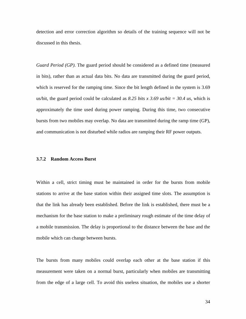
Figure 3.13. Structure of a random access burst.
Figure 3.13 shows the content of a random access burst. The interpretation of the bits
within the burst is similar to the normal burst. The synchronization sequence serves the
same purpose as the training sequence. The obvious difference is that the synchronization
sequence is much longer because the equalizer needs more information; it needs to take a
longer look to synchronize properly with a new signal.
The synchronization sequence has a long guard period, namely, 68.25 bits x 3.69 us/bit =
252 us. The guard period needs to be long enough to insure that the base station can
respond before the end of the burst. The maximum distance that a signal can travel during
the guard time is 252 us x (3 x 108 m/s) = 75.5 km. Since radio waves have to travel twice
T 8
Type Number of bits
Synchronization Seq. 41
Coded Data 36
T 3
GP 68.25
88 Bit * 3.69us/bit = 324.72 us
36
the distance between stations in order to complete the establishment of the link, the
maximum distance between the mobile station and the base station is 37.75 km.
3.7.3 Synchronization Burst
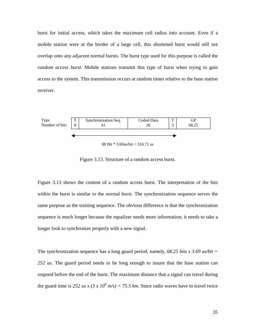
Figure 3.14. Structure of a synchronization burst.
When a mobile station starts to synchronize with the network, it first looks for and detects
only the frequency of the base channel through a special kind of burst structure
(Frequency-Correction Burst). The mobile does not yet have a key with which to
demodulate and decode the information provided in the forward base channel, which is
information that contains the system parameters. As was explained previously, the key is
one of the eight defined training sequences. The base tells the mobile which key to use
with the synchronization burst. Figure 3.14 shows the structure of this burst type, which
is similar to the normal burst. The difference is the longer synchronization sequence and
less coded data. The coded data contains the base station information code (BSIC)
Type Number of bits
T 3
Coded data 39
Synchronization Sequence 64
Coded data 39
T 3
GP 8.25
148 Bit * 3.69 us/bit = 546.12 us
37
indicating the current training sequence (base station color code (BCC)) and the national
color code (NCC), and another figure indicating the so-called shortened TDMA frame
number.
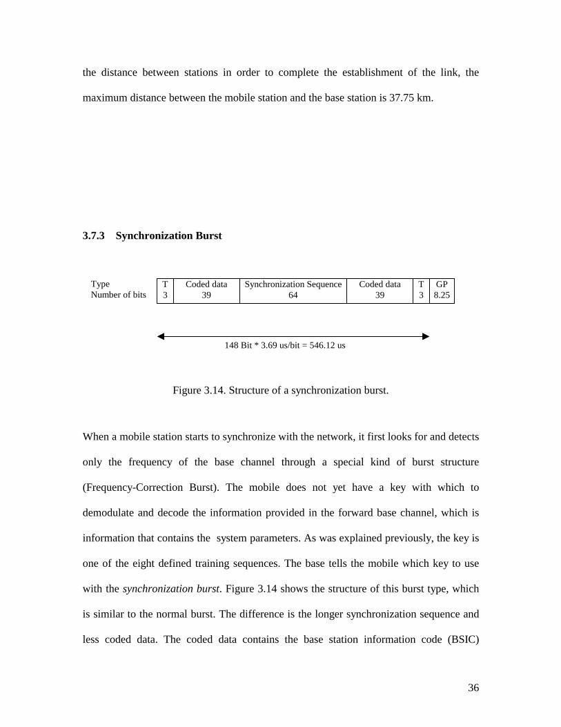
Figure 3.15 lists the three kinds of burst structure
Burst NORMAL ACCESS SYNCHRONIZE
Tail
Encrypted
Training
Encrypted
Tail
3 zeroes
58
26
58
3 zeroes
8
0
41
36
3 zeroes
3 zeroes
39
64
39
3 zeroes
Total 148 88 148
Figure 3.15. Burst structures in a GSM system.
3.8 Differential Encoder
Differential encoding is not channel coding, it is part of digital modulation. At the lowest
level of the physical interface between radios in the GSM system, the voice is digitized
38
and encoded into multi-frames so that they can be mapped into time slots and bursts. All
that remains is to modulate a radio carrier with the myriad bits. The digital modulation is
a binary waveform superimposed on an RF carrier.
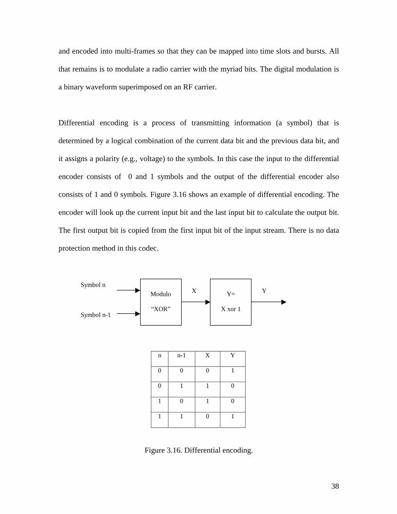
Differential encoding is a process of transmitting information (a symbol) that is
determined by a logical combination of the current data bit and the previous data bit, and
it assigns a polarity (e.g., voltage) to the symbols. In this case the input to the differential
encoder consists of 0 and 1 symbols and the output of the differential encoder also
consists of 1 and 0 symbols. Figure 3.16 shows an example of differential encoding. The
encoder will look up the current input bit and the last input bit to calculate the output bit.
The first output bit is copied from the first input bit of the input stream. There is no data
protection method in this codec.
n n-1 X Y
0 0 0 1
0 1 1 0
1 0 1 0
1 1 0 1
Figure 3.16. Differential encoding.
Modulo
“XOR”
Symbol n Symbol n-1
X
Y=
X xor 1
Y
39
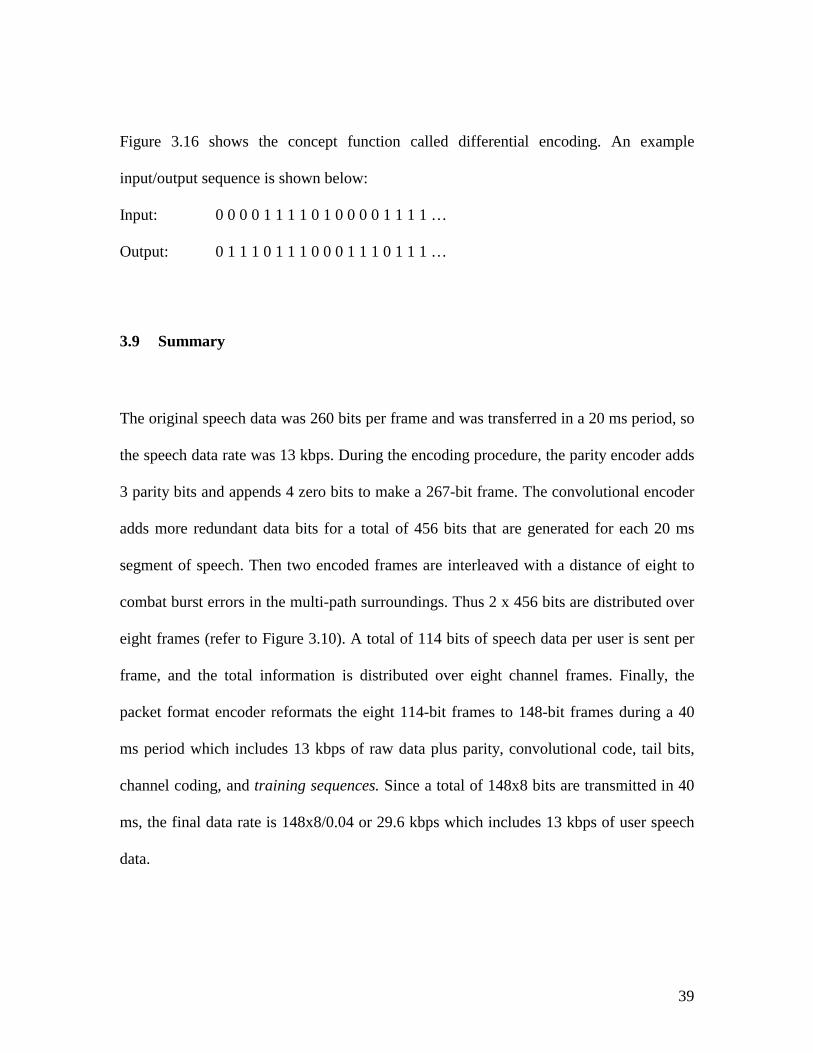
Figure 3.16 shows the concept function called differential encoding. An example
input/output sequence is shown below:
Input: 0 0 0 0 1 1 1 1 0 1 0 0 0 0 1 1 1 1 …
Output: 0 1 1 1 0 1 1 1 0 0 0 1 1 1 0 1 1 1 …
3.9 Summary
The original speech data was 260 bits per frame and was transferred in a 20 ms period, so
the speech data rate was 13 kbps. During the encoding procedure, the parity encoder adds
3 parity bits and appends 4 zero bits to make a 267-bit frame. The convolutional encoder
adds more redundant data bits for a total of 456 bits that are generated for each 20 ms
segment of speech. Then two encoded frames are interleaved with a distance of eight to
combat burst errors in the multi-path surroundings. Thus 2 x 456 bits are distributed over
eight frames (refer to Figure 3.10). A total of 114 bits of speech data per user is sent per
frame, and the total information is distributed over eight channel frames. Finally, the
packet format encoder reformats the eight 114-bit frames to 148-bit frames during a 40
ms period which includes 13 kbps of raw data plus parity, convolutional code, tail bits,
channel coding, and training sequences. Since a total of 148x8 bits are transmitted in 40
ms, the final data rate is 148x8/0.04 or 29.6 kbps which includes 13 kbps of user speech
data.
40
Chapter 4. Implementation of decoders
Chapter 4 describes the five different decoders used for decoding the speech data. Each
decoder is paired with its corresponding encoder described in chapter 3. All the encoder
and decoder models are implemented by VHDL in this project.
4.1 Differential Decoder
As illustrated in the last chapter, the differential encoder used in this system performs the
calculation of the current input bit and the last input bit to simulate modulating the digital
binary signal to the polarity symbols, so the differential decoder transforms the polarity
value back to the binary data stream. The decoder will look up the current input bit and
the last decoded bit to calculate the current decoded bit. The first output bit is copied
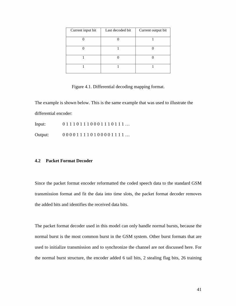
from the first input bit of the input data stream. The differential decoding mapping format
is shown in Figure 4.1.
41
Current input bit Last decoded bit Current output bit
0 0 1
0 1 0
1 0 0
1 1 1
Figure 4.1. Differential decoding mapping format.
The example is shown below. This is the same example that was used to illustrate the
differential encoder:
Input: 0 1 1 1 0 1 1 1 0 0 0 1 1 1 0 1 1 1 …
Output: 0 0 0 0 1 1 1 1 0 1 0 0 0 0 1 1 1 1 …
4.2 Packet Format Decoder
Since the packet format encoder reformatted the coded speech data to the standard GSM
transmission format and fit the data into time slots, the packet format decoder removes
the added bits and identifies the received data bits.
The packet format decoder used in this model can only handle normal bursts, because the
normal burst is the most common burst in the GSM system. Other burst formats that are
used to initialize transmission and to synchronize the channel are not discussed here. For
the normal burst structure, the encoder added 6 tail bits, 2 stealing flag bits, 26 training
42
sequence bits and a guard period to the original data frame to form a GSM time slot with
standard GSM transmission format.
Each input frame has 8 sub-frames and each sub-frame has 148 bits as the input data
stream that comes from the differential decoder. After taking out the 34 bits of added data
in each sub-frame, which are 6 tail bits, 2 stealing flag bits and 26 training sequence bits,
the output data stream contains the same 8 sub-frames and each sub-frame has 114 bits of
encoded speech data consisting of two 57-bit sub-blocks. For details, refer to the packet
format encoder.
4.3 Interleaver Decoder
The interleaver decoder corresponds to the interleaver encoder described in the last
chapter. The purpose of interleaving is to help the convolutional code to correct burst
errors. Since the convolutional code works much better for random single bit errors than
for a burst error, the possibility of uncorrected burst errors will be significantly reduced
after the interleaving process.
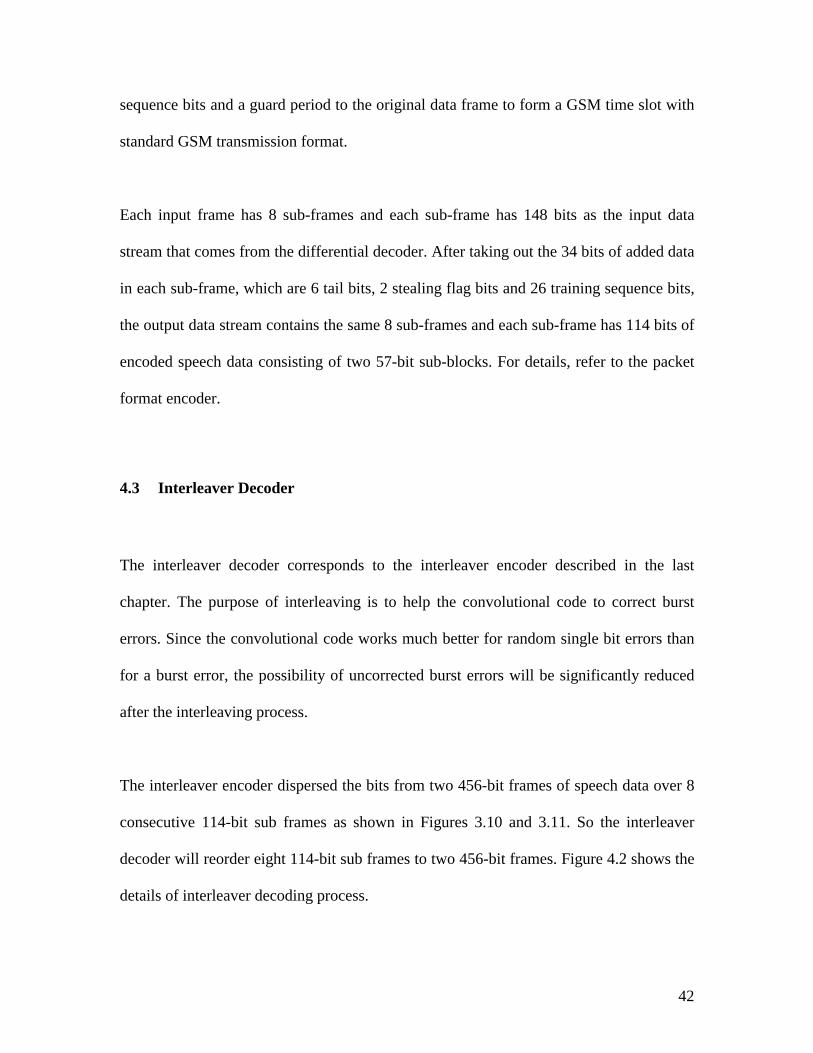
The interleaver encoder dispersed the bits from two 456-bit frames of speech data over 8
consecutive 114-bit sub frames as shown in Figures 3.10 and 3.11. So the interleaver
decoder will reorder eight 114-bit sub frames to two 456-bit frames. Figure 4.2 shows the
details of interleaver decoding process.
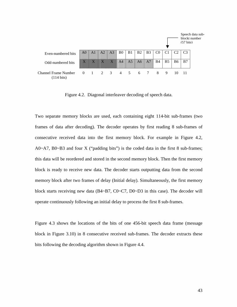
Figure 4.2. Diagonal interleaver decoding of speech data.
Two separate memory blocks are used, each containing eight 114-bit sub-
frames of data after decoding). The decoder operates by first reading 8 su
consecutive received data into the first memory block. For example in
A0~A7, B0~B3 and four X (“padding bits”) is the coded data in the first 8
this data will be reordered and stored in the second memory block. Then the
block is ready to receive new data. The decoder starts outputting data from
memory block after two frames of delay (Initial delay). Simultaneously, the f
block starts receiving new data (B4~B7, C0~C7, D0~D3 in this case). The
operate continuously following an initial delay to process the first 8 sub-frame
Figure 4.3 shows the locations of the bits of one 456-bit speech data fram
block in Figure 3.10) in 8 consecutive received sub-frames. The decoder e
bits following the decoding algorithm shown in Figure 4.4.
A0 A1 A2 A3 B0 B1 B2 B3 C0 C1 C2
X X X X A4 A5 A6 A7 B4 B5 B6
Even-numbered bits Odd-numbered bits
Channel Frame Number 0 1 2 3 4 5 6 7 8 9 10 (114 bits)
Speech data sub-blockt number (57 bits)
43
frames (two
b-frames of
Figure 4.2,
sub-frames;
first memory
the second
irst memory
decoder will
s.
e (message
xtracts these
C3
B7
11
44
Position Within the 26-Frame Structure (sub frame)
Even bits of frame number N 0 8 …………….448 Even bits of frame number N + 1 1 9 …………….449 Even bits of frame number N + 2 2 10 …………….450 Even bits of frame number N + 3 3 11 …………….451 Odd bits of frame number N + 4 4 12 …………….452 Odd bits of frame number N + 5 5 13 …………….453 Odd bits of frame number N + 6 6 14 …………….454 Odd bits of frame number N + 7 7 15 …………….455
Figure 4.3. Reordering scheme for a traffic channel TCH.
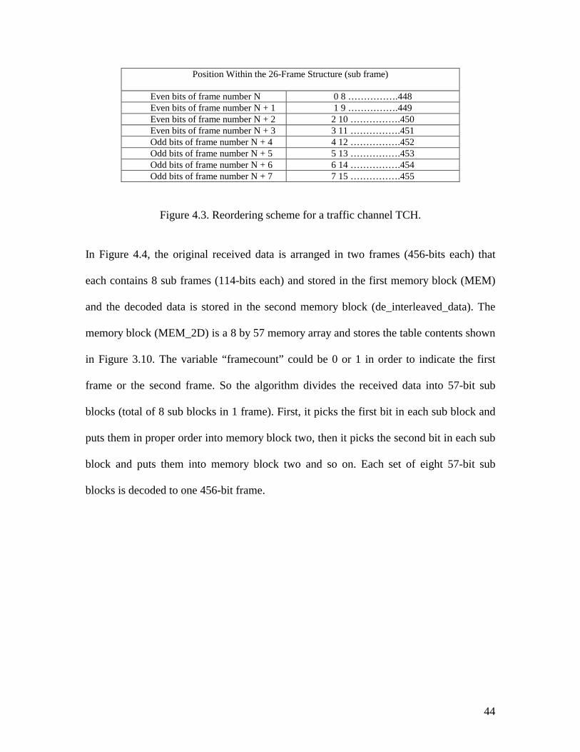
In Figure 4.4, the original received data is arranged in two frames (456-bits each) that
each contains 8 sub frames (114-bits each) and stored in the first memory block (MEM)
and the decoded data is stored in the second memory block (de_interleaved_data). The
memory block (MEM_2D) is a 8 by 57 memory array and stores the table contents shown
in Figure 3.10. The variable “framecount” could be 0 or 1 in order to indicate the first
frame or the second frame. So the algorithm divides the received data into 57-bit sub
blocks (total of 8 sub blocks in 1 frame). First, it picks the first bit in each sub block and
puts them in proper order into memory block two, then it picks the second bit in each sub
block and puts them into memory block two and so on. Each set of eight 57-bit sub
blocks is decoded to one 456-bit frame.
45
Figure 4.4. Interleaver decoding algorithm.
4.4 Viterbi Decoder
The Viterbi decoder is the most important part in the receiver; the Viterbi algorithm is
one of the most common decoding algorithms used for decoding convolutional codes.
In 1967, Viterbi introduced a decoding algorithm for convolutional codes which has since
become known as the Viterbi algorithm [17]. Later, Omura showed that the Viterbi
algorithm was equivalent to a dynamic programming solution to the problem of finding
the shortest path through a weighted graph [17]. Finally, Forney recognized that it was, in
-- reorder row 4,0; 5,1; 6,2; 7,3 subblocks to 0,1,2,3,4,5,6,7-- restore to original 8 by 57 matrix sequence
for k in 0 to 56 loopMEM_2D(4,k):=MEM(framecount,k*2+57*0+1);MEM_2D(0,k):=MEM(framecount,k*2+1+57*0+1);MEM_2D(5,k):=MEM(framecount,k*2+57*2+1);MEM_2D(1,k):=MEM(framecount,k*2+1+57*2+1);MEM_2D(6,k):=MEM(framecount,k*2+57*4+1);MEM_2D(2,k):=MEM(framecount,k*2+1+57*4+1);MEM_2D(7,k):=MEM(framecount,k*2+57*6+1);MEM_2D(3,k):=MEM(framecount,k*2+1+57*6+1);
end loop;
-- put data from 8 by 57 matrix back to original frame.
for row in 0 to 56 loopfor column in 0 to 7 loop
de_interleaved_data(framecount,row*8+column):=MEM_2D(column,row);end loop;
end loop;
46
fact, a maximum likelihood decoding algorithm for convolutional codes; the decoder
output selected is always the code word that gives the largest value of the log-likelihood
function [17].
Forney also was the first to point out that the Viterbi algorithm could be used to produce
the maximum likelihood estimate of the transmitted sequence over a band-limited
channel with inter-symbol interference [17].
To understand Viterbi’s decoding algorithm, it is convenient to expand the state diagram
of the encoder in time, i.e., to represent each time unit with a separate state diagram. The
resulting structure is called a trellis diagram.
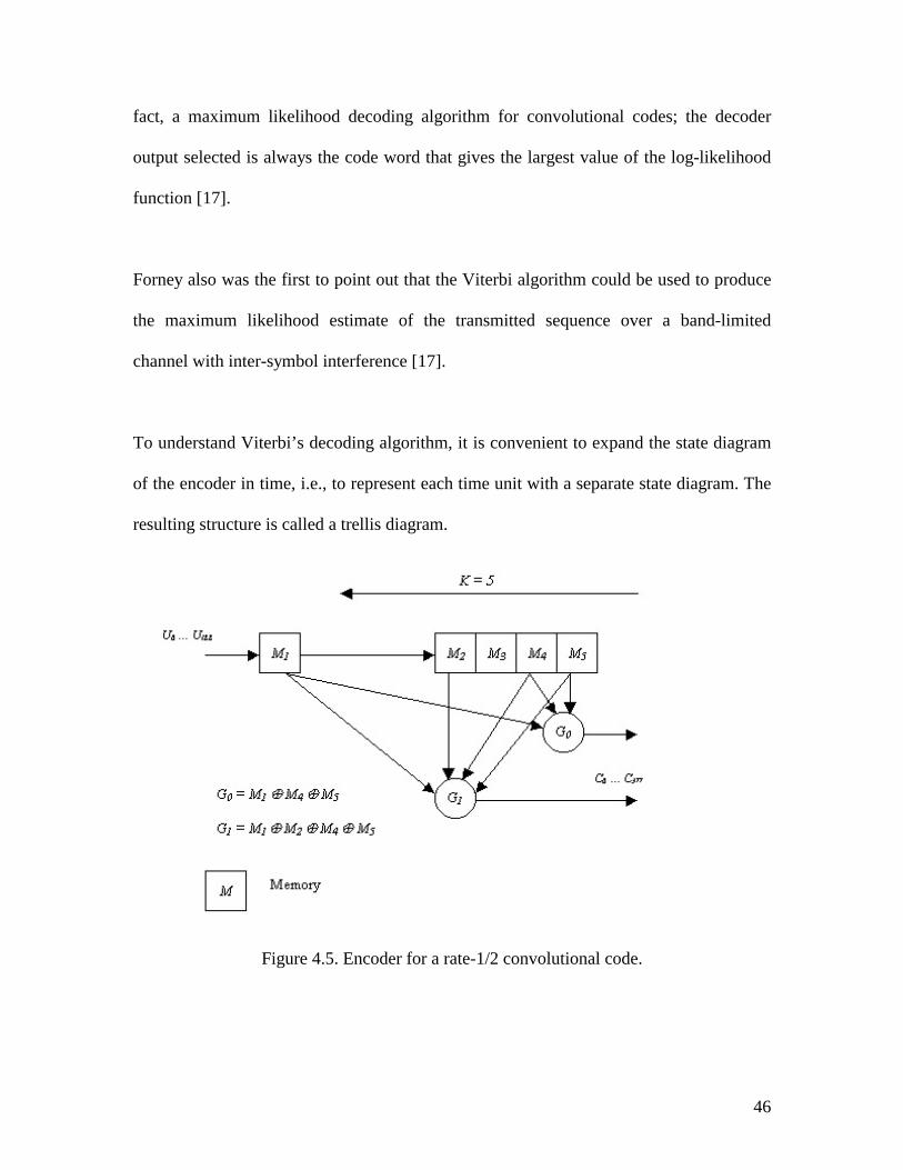
Figure 4.5. Encoder for a rate-1/2 convolutional code.
47
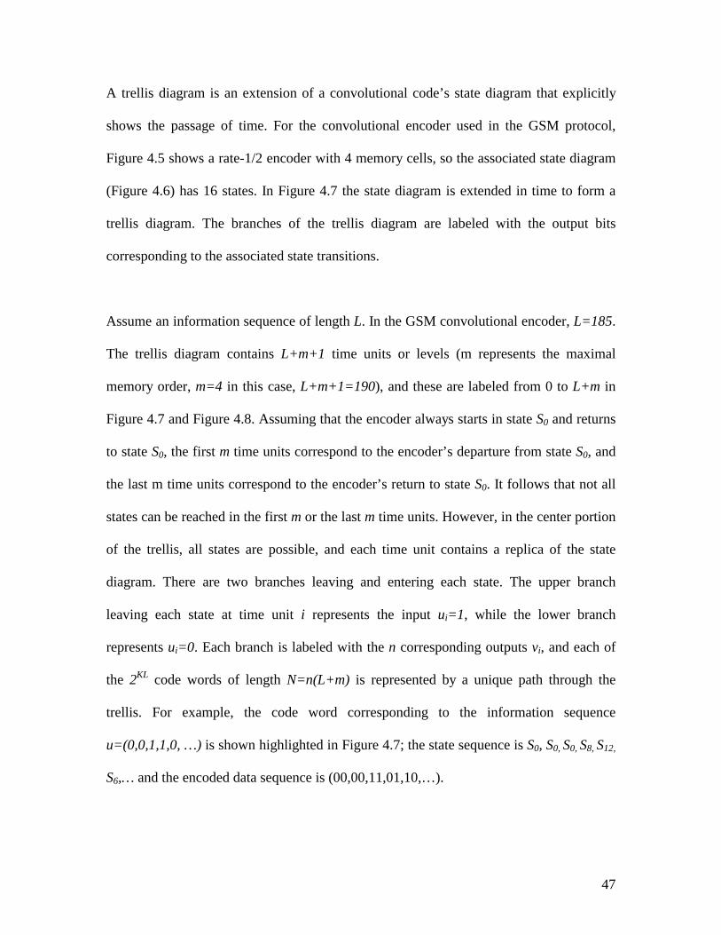
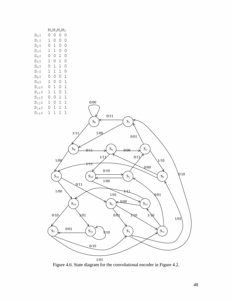
A trellis diagram is an extension of a convolutional code’s state diagram that explicitly
shows the passage of time. For the convolutional encoder used in the GSM protocol,
Figure 4.5 shows a rate-1/2 encoder with 4 memory cells, so the associated state diagram
(Figure 4.6) has 16 states. In Figure 4.7 the state diagram is extended in time to form a
trellis diagram. The branches of the trellis diagram are labeled with the output bits
corresponding to the associated state transitions.
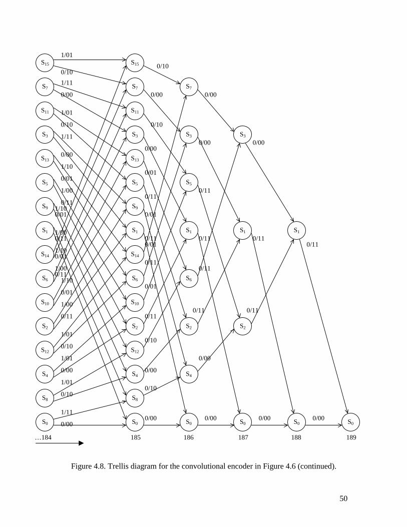
Assume an information sequence of length L. In the GSM convolutional encoder, L=185.
The trellis diagram contains L+m+1 time units or levels (m represents the maximal
memory order, m=4 in this case, L+m+1=190), and these are labeled from 0 to L+m in
Figure 4.7 and Figure 4.8. Assuming that the encoder always starts in state S0 and returns
to state S0, the first m time units correspond to the encoder’s departure from state S0, and
the last m time units correspond to the encoder’s return to state S0. It follows that not all
states can be reached in the first m or the last m time units. However, in the center portion
of the trellis, all states are possible, and each time unit contains a replica of the state
diagram. There are two branches leaving and entering each state. The upper branch
leaving each state at time unit i represents the input ui=1, while the lower branch
represents ui=0. Each branch is labeled with the n corresponding outputs vi, and each of
the 2KL code words of length N=n(L+m) is represented by a unique path through the
trellis. For example, the code word corresponding to the information sequence
u=(0,0,1,1,0, …) is shown highlighted in Figure 4.7; the state sequence is S0, S0, S0, S8, S12,
S6,… and the encoded data sequence is (00,00,11,01,10,…).
48
M2M3M4M5S0: 0 0 0 0S1: 1 0 0 0S2: 0 1 0 0S3: 1 1 0 0S4: 0 0 1 0S5: 1 0 1 0S6: 0 1 1 0S7: 1 1 1 0S8: 0 0 0 1S9: 1 0 0 1S10: 0 1 0 1S11: 1 1 0 1S12: 0 0 1 1S13: 1 0 1 1S14: 0 1 1 1S15: 1 1 1 1
Figure 4.6. State diagram for the convolutional encoder in Figure 4.2.
S0 S1
S8 S4 S2
S12 S10 S5 S9
S14 S6 S13
S7 S15 S3 S11
0/11
0/00
1/11
1/00
1/00 0/01
0/11 0/00
1/10
0/10
1/01
1/11
1/00
0/11
0/10
1/00
0/01
0/11
0/00
1/11 1/01
0/00
1/10 1/10 0/01 1/01 0/10
0/01 1/10
0/10
1/01
1/11
Figure 4.7. Trellis diagram for the convolutional encoder in
S15
S7
S11
S3
S13
S5
S9
S1
S14
S6
S10
S2
S12
S4
S8
S0
S14
S6
S10
S2
S12
S4
S8
S0
S12
S4
S8
S0
S8
S0 S0
1/10
1/01
0/01
0/10 0/11
0/01 1/01
1/11
1/00
0/11 0/00 0/10
1/01
1/10
1/01
1/11
1/10/0
1/00/1
1/11
1/10/0
1/00/1
0/10 0/00
1/01
0/10 1/11
1/11
0/00 0/00 0/00
1/11
0/00
1/00
1/10
1/01
S15S7
S11
S3
S13
S5
S9
S1
S14
S6
S10
S2
S12
S4
S8
S0
0/10 1/11
0/00
1/01
0/10
1/11
0/00
1/10
0/01
1/00
0/11 0 1
0 1
0 1
0 1
1/10
0/01
1/00
0/11
1/01
0/10
1/01
0/00
1/01
0/10
1/11
0/00
0 1 2 3 4 5 ……
49
Figure 4.6.
S15
S7
S11
S3
S13
S5
S9
S1
S14
S6
S10
S2
S12
S4
S8
S0
1/10/0
1/00/1
1/10/0
1/00/1
1/01
S15S7
S11
S3
S13
S5
S9
S1
S14
S6
S10
S2
S12
S4
S8
S0
0/10 1/11
0/00
1/01
0/10
1/11
0/00
1/10
0/01
1/00
0/11 0 1
0 1
0 1
0 1
1/10
0/01
1/00
0/11
1/01
0/10
1/01
0/00
1/01
0/10
1/11
0/00
S7
S3
S5
S1
S6
S2
S4
S0
S3
S1
S2
S0
S1
S0 S0
0/10
0/00
0/10
0/00
0/01
0/11
0/01
0/11 0/01
0/11
0/01
0/11
0/10
0/00
0/10
0/00 0/00 0/00 0/00
0/00
0/11 0/11
0/11
0/11 0/11 0/11
0/11
0/00 0/00
0/00
…184 185 186 187 188 189
50
Figure 4.8. Trellis diagram for the convolutional encoder in Figure 4.6 (continued).
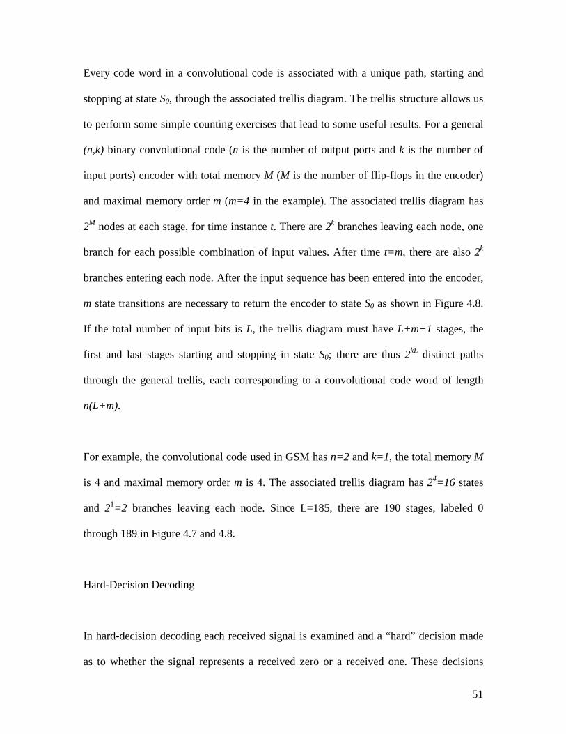
51
Every code word in a convolutional code is associated with a unique path, starting and
stopping at state S0, through the associated trellis diagram. The trellis structure allows us
to perform some simple counting exercises that lead to some useful results. For a general
(n,k) binary convolutional code (n is the number of output ports and k is the number of
input ports) encoder with total memory M (M is the number of flip-flops in the encoder)
and maximal memory order m (m=4 in the example). The associated trellis diagram has
2M nodes at each stage, for time instance t. There are 2k branches leaving each node, one
branch for each possible combination of input values. After time t=m, there are also 2k
branches entering each node. After the input sequence has been entered into the encoder,
m state transitions are necessary to return the encoder to state S0 as shown in Figure 4.8.
If the total number of input bits is L, the trellis diagram must have L+m+1 stages, the
first and last stages starting and stopping in state S0; there are thus 2kL distinct paths
through the general trellis, each corresponding to a convolutional code word of length
n(L+m).
For example, the convolutional code used in GSM has n=2 and k=1, the total memory M
is 4 and maximal memory order m is 4. The associated trellis diagram has 24=16 states
and 21=2 branches leaving each node. Since L=185, there are 190 stages, labeled 0
through 189 in Figure 4.7 and 4.8.
Hard-Decision Decoding
In hard-decision decoding each received signal is examined and a “hard” decision made
as to whether the signal represents a received zero or a received one. These decisions
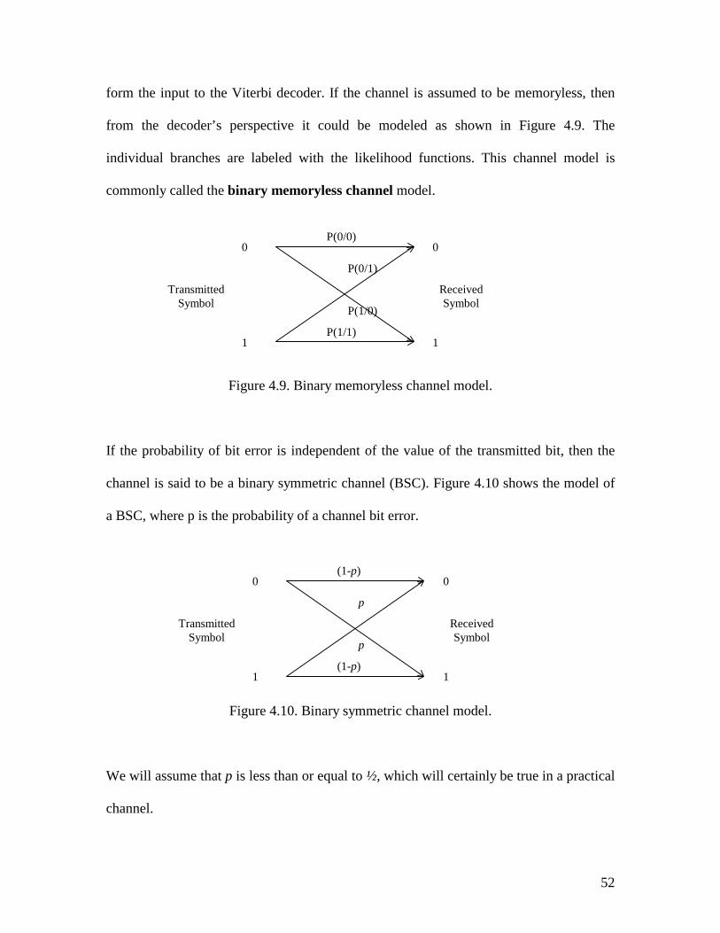
52
form the input to the Viterbi decoder. If the channel is assumed to be memoryless, then
from the decoder’s perspective it could be modeled as shown in Figure 4.9. The
individual branches are labeled with the likelihood functions. This channel model is
commonly called the binary memoryless channel model.
Figure 4.9. Binary memoryless channel model.
If the probability of bit error is independent of the value of the transmitted bit, then the
channel is said to be a binary symmetric channel (BSC). Figure 4.10 shows the model of
a BSC, where p is the probability of a channel bit error.
Figure 4.10. Binary symmetric channel model.
We will assume that p is less than or equal to ½, which will certainly be true in a practical
channel.
0
1 1
0
Transmitted Symbol
Received Symbol
P(0/0)
P(0/1)
P(1/0)
P(1/1)
0
1 1
0
Transmitted Symbol
Received Symbol
(1-p)
p
p
(1-p)
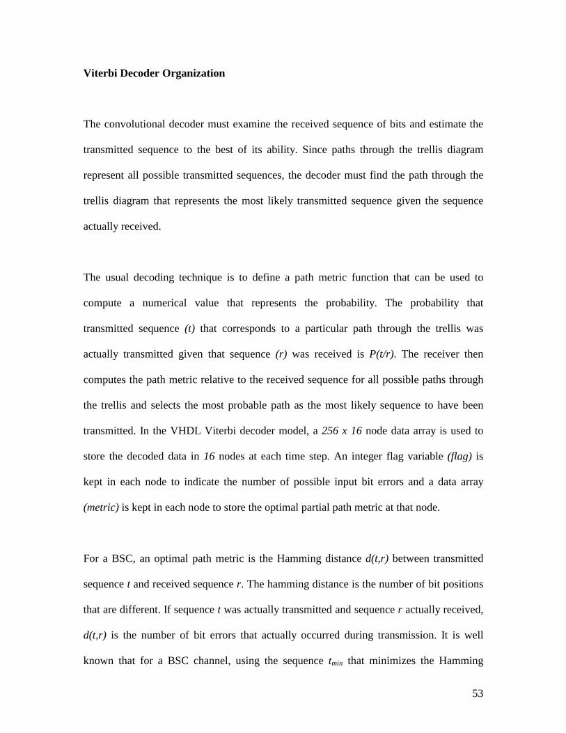
53
Viterbi Decoder Organization
The convolutional decoder must examine the received sequence of bits and estimate the
transmitted sequence to the best of its ability. Since paths through the trellis diagram
represent all possible transmitted sequences, the decoder must find the path through the
trellis diagram that represents the most likely transmitted sequence given the sequence
actually received.
The usual decoding technique is to define a path metric function that can be used to
compute a numerical value that represents the probability. The probability that
transmitted sequence (t) that corresponds to a particular path through the trellis was
actually transmitted given that sequence (r) was received is P(t/r). The receiver then
computes the path metric relative to the received sequence for all possible paths through
the trellis and selects the most probable path as the most likely sequence to have been
transmitted. In the VHDL Viterbi decoder model, a 256 x 16 node data array is used to
store the decoded data in 16 nodes at each time step. An integer flag variable (flag) is
kept in each node to indicate the number of possible input bit errors and a data array
(metric) is kept in each node to store the optimal partial path metric at that node.
For a BSC, an optimal path metric is the Hamming distance d(t,r) between transmitted
sequence t and received sequence r. The hamming distance is the number of bit positions
that are different. If sequence t was actually transmitted and sequence r actually received,
d(t,r) is the number of bit errors that actually occurred during transmission. It is well
known that for a BSC channel, using the sequence tmin that minimizes the Hamming
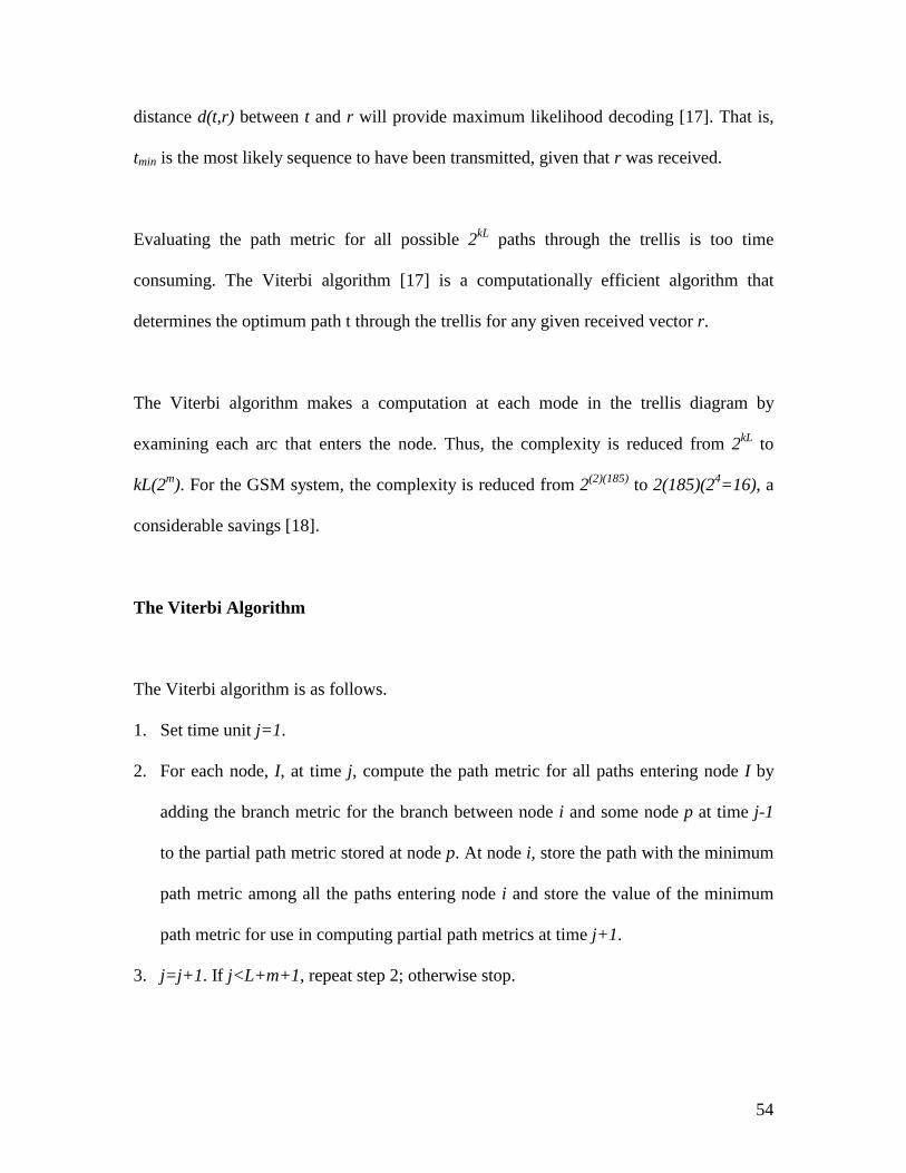
54
distance d(t,r) between t and r will provide maximum likelihood decoding [17]. That is,
tmin is the most likely sequence to have been transmitted, given that r was received.
Evaluating the path metric for all possible 2kL paths through the trellis is too time
consuming. The Viterbi algorithm [17] is a computationally efficient algorithm that
determines the optimum path t through the trellis for any given received vector r.
The Viterbi algorithm makes a computation at each mode in the trellis diagram by
examining each arc that enters the node. Thus, the complexity is reduced from 2kL to
kL(2m). For the GSM system, the complexity is reduced from 2(2)(185) to 2(185)(24=16), a
considerable savings [18].
The Viterbi Algorithm
The Viterbi algorithm is as follows.
1. Set time unit j=1.
2. For each node, I, at time j, compute the path metric for all paths entering node I by
adding the branch metric for the branch between node i and some node p at time j-1
to the partial path metric stored at node p. At node i, store the path with the minimum
path metric among all the paths entering node i and store the value of the minimum
path metric for use in computing partial path metrics at time j+1.
3. j=j+1. If j<L+m+1, repeat step 2; otherwise stop.
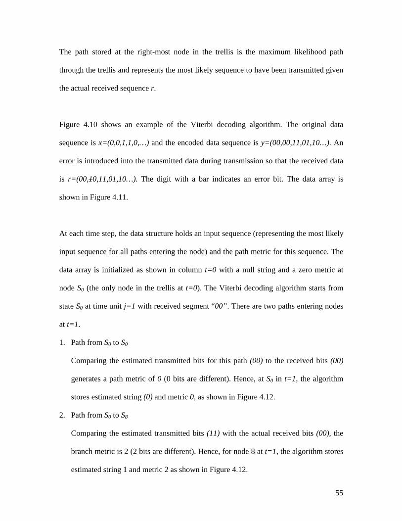
55
The path stored at the right-most node in the trellis is the maximum likelihood path
through the trellis and represents the most likely sequence to have been transmitted given
the actual received sequence r.
Figure 4.10 shows an example of the Viterbi decoding algorithm. The original data
sequence is x=(0,0,1,1,0,…) and the encoded data sequence is y=(00,00,11,01,10…). An
error is introduced into the transmitted data during transmission so that the received data
is r=(00,10,11,01,10…). The digit with a bar indicates an error bit. The data array is
shown in Figure 4.11.
At each time step, the data structure holds an input sequence (representing the most likely
input sequence for all paths entering the node) and the path metric for this sequence. The
data array is initialized as shown in column t=0 with a null string and a zero metric at
node S0 (the only node in the trellis at t=0). The Viterbi decoding algorithm starts from
state S0 at time unit j=1 with received segment “00”. There are two paths entering nodes
at t=1.
1. Path from S0 to S0
Comparing the estimated transmitted bits for this path (00) to the received bits (00)
generates a path metric of 0 (0 bits are different). Hence, at S0 in t=1, the algorithm
stores estimated string (0) and metric 0, as shown in Figure 4.12.
2. Path from S0 to S8
Comparing the estimated transmitted bits (11) with the actual received bits (00), the
branch metric is 2 (2 bits are different). Hence, for node 8 at t=1, the algorithm stores
estimated string 1 and metric 2 as shown in Figure 4.12.
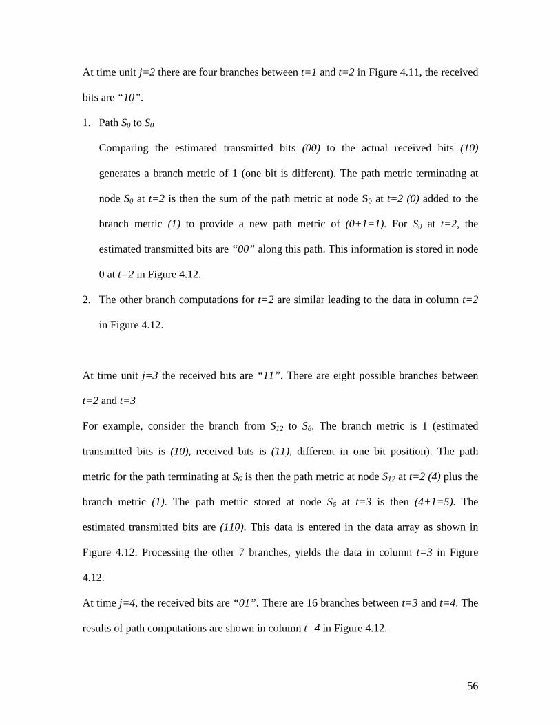
56
At time unit j=2 there are four branches between t=1 and t=2 in Figure 4.11, the received
bits are “10”.
1. Path S0 to S0
Comparing the estimated transmitted bits (00) to the actual received bits (10)
generates a branch metric of 1 (one bit is different). The path metric terminating at
node S0 at t=2 is then the sum of the path metric at node S0 at t=2 (0) added to the
branch metric (1) to provide a new path metric of (0+1=1). For S0 at t=2, the
estimated transmitted bits are “00” along this path. This information is stored in node
0 at t=2 in Figure 4.12.
2. The other branch computations for t=2 are similar leading to the data in column t=2
in Figure 4.12.
At time unit j=3 the received bits are “11”. There are eight possible branches between
t=2 and t=3
For example, consider the branch from S12 to S6. The branch metric is 1 (estimated
transmitted bits is (10), received bits is (11), different in one bit position). The path
metric for the path terminating at S6 is then the path metric at node S12 at t=2 (4) plus the
branch metric (1). The path metric stored at node S6 at t=3 is then (4+1=5). The
estimated transmitted bits are (110). This data is entered in the data array as shown in
Figure 4.12. Processing the other 7 branches, yields the data in column t=3 in Figure
4.12.
At time j=4, the received bits are “01”. There are 16 branches between t=3 and t=4. The
results of path computations are shown in column t=4 in Figure 4.12.
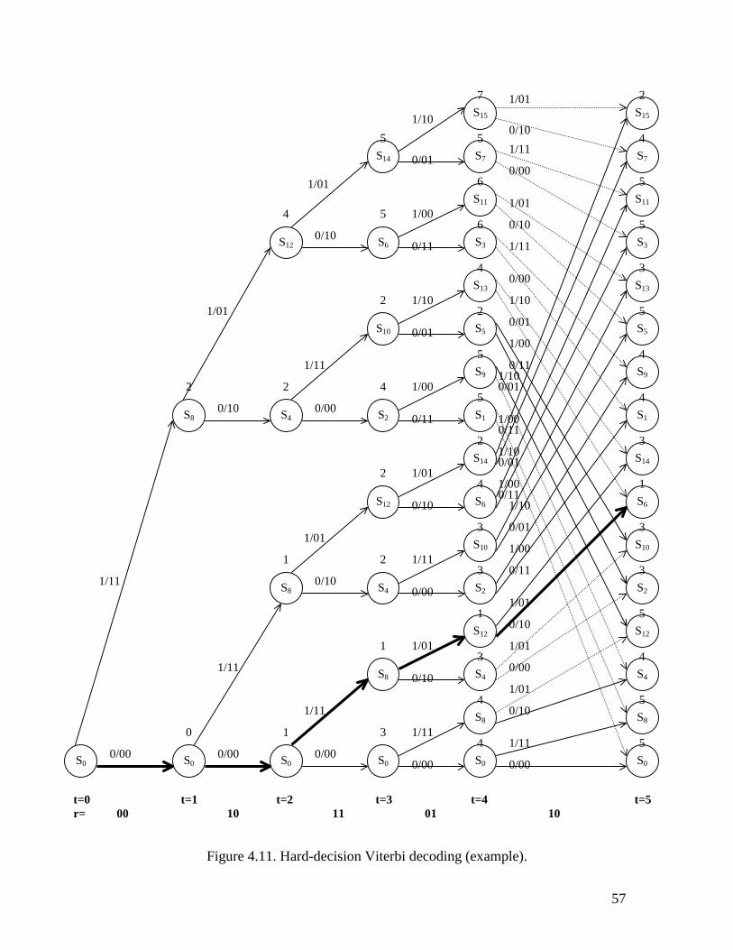
Figure 4.11. Hard-decision Viterbi decoding (examp
S15
S7
S11
S3
S13
S5
S9
S1
S14
S6
S10
S2
S12
S4
S8
S0
S14
S6
S10
S2
S12
S4
S8
S0
S12
S4
S8
S0
S8
S0 S0
1/10
1/01
0/01
0/10 0/11
0/01
1/01
1/11
1/00
0/11 0/00 0/10
1/01
0/10
1/01
1/11
1/10/0
1/00/1
1/11
1/10/0
1/00/1
0/10 0/00
1/01
0/10 1/11
1/11
0/00 0/00 0/00
1/11
0/00
1/00
1/10
t=0 t=1 t=2 t=3 t=4 r= 00 10 11 01
0
2
1
1
2
4
1
3
2
2
4
5
2
4
4
3
1
3
3
4
2
5
5
2
4
6
6
5 5
7 2
1/0157
le).
S15
S7
S11
S3
S13
S5
S9
S1
S14
S6
S10
S2
S12
S4
S8
S0
0/10 1/11
0/00
1/01
0/10
1/11
0/00
1/10
0/01
1/00
0/11 0 1
0 1
0 1
0 1
1/10
0/01
1/00
0/11
1/01
0/10
1/01
0/00
1/01
0/10
1/11
0/00
t=5 10
5
5
4
5
3
3
1
3
4
4
5
3
5
5
4
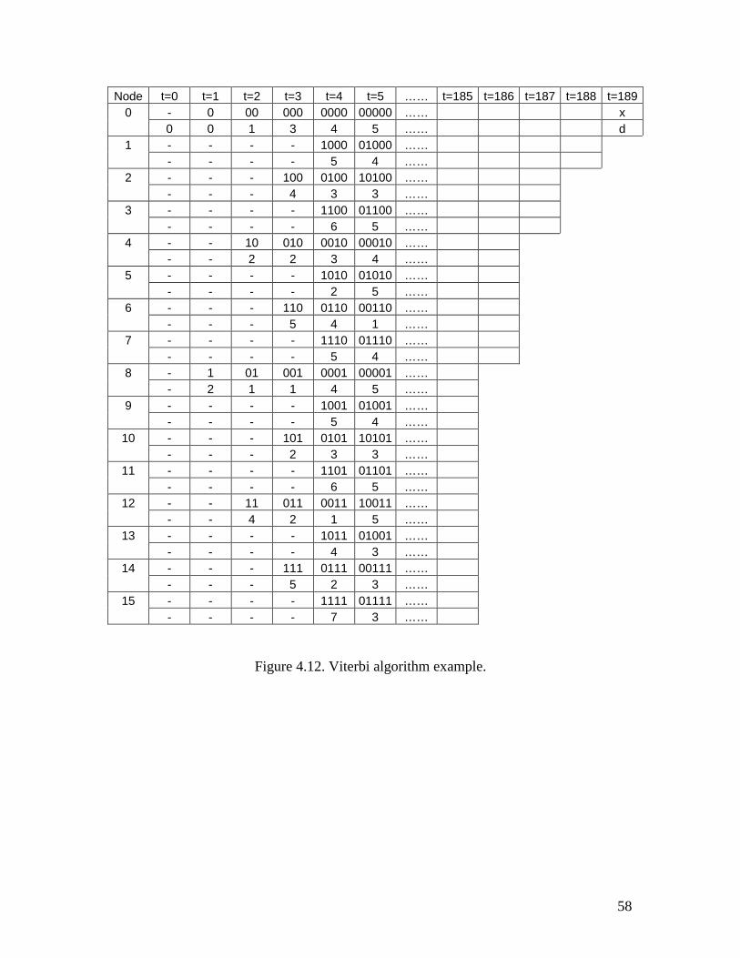
58
Node t=0 t=1 t=2 t=3 t=4 t=5 …… t=185 t=186 t=187 t=188 t=1890 - 0 00 000 0000 00000 …… x 0 0 1 3 4 5 …… d 1 - - - - 1000 01000 …… - - - - 5 4 …… 2 - - - 100 0100 10100 …… - - - 4 3 3 …… 3 - - - - 1100 01100 …… - - - - 6 5 …… 4 - - 10 010 0010 00010 …… - - 2 2 3 4 …… 5 - - - - 1010 01010 …… - - - - 2 5 …… 6 - - - 110 0110 00110 …… - - - 5 4 1 …… 7 - - - - 1110 01110 …… - - - - 5 4 …… 8 - 1 01 001 0001 00001 …… - 2 1 1 4 5 …… 9 - - - - 1001 01001 …… - - - - 5 4 ……
10 - - - 101 0101 10101 …… - - - 2 3 3 ……
11 - - - - 1101 01101 …… - - - - 6 5 ……
12 - - 11 011 0011 10011 …… - - 4 2 1 5 ……
13 - - - - 1011 01001 …… - - - - 4 3 ……
14 - - - 111 0111 00111 …… - - - 5 2 3 ……
15 - - - - 1111 01111 …… - - - - 7 3 ……
Figure 4.12. Viterbi algorithm example.
59
At time j=5, the algorithm becomes more complex since there are now 32 branches
between t=4 and t=5 in Figure 4.11. But, we only want to keep 16 of the paths, one
terminating at each node at t=6. To illustrate the calculation, consider the calculation for
node S14 at t=5. There are two branches entering node S14 at t=5. For the branch from S12
(at t=4) to S14 (at t=5), the branch metric is 2 (estimated transmitted bits 01, actual
received bits 10, different in 2 bit positions). The path metric using this branch then has
metric 3 (path metric at S12 for t=4 (1) plus the branch metric (2)). For the branch from
S13 (at t=4) to S14 (at t=5), the branch metric is 0 (estimated transmitted bits 10 and the
actual received bits 10). The path metric using this branch is then 4 (path metric at node
S13 at t=4 (4) plus the branch metric (0)). The minimum of the two computed metrics is
min(3,4)=3, which corresponds to the path from S12 to S14. The estimated transmitted bits
along this path are 00111. The data entry for S14 at t=5 is thus path 00111, metric=3, as
indicated in column t=5 of Figure 4.12. Similar computations lead to the remaining data
in column t=5 of Figure 4.12.
As shown in Figure 4.8, the possible set of states decreases starting at t=186. This is
reflected in the data structure of Figure 4.12 by showing only boxes for S0, S1, … , S7. At
t=187, the only possible states are S0, S1, S2, S3. At t=188, only S1 and S0 are possible. At
t=189, the state must be S0. As shown in Figure 4.12, the data entry for node S0 is (x, d);
string x is the maximum likelihood estimate for the transmitted data and d is the metric
reflecting the distance between the transmitted sequence, t, and the received sequence, r.
60
4.5 Parity Check Decoder
As illustrated in an earlier chapter, the parity code is an error detection code. For the
GSM coding system, 3 parity bits are added to protect the first 50 bits of data (Class 1a)
that are considered to be the most important data bits in the frame. Then 4 zero bits are
added after the Class 1b bits (bits 186 to 189).
The parity check decoder will re-compute the 3 parity bits using the received data bits
and compare them with the received parity bits. If the received parity bits do not match
the re-computed parity bits, an error is detected; the system will report an error message
during the simulation, such as:
“ParityCheck: Error(94)!"
This output message indicates that uncorrectable errors are present in the decoded data
stream and the 94th bit in the decoded data stream (checking bit) does not match. The
frame will be ignored.
Except for checking the 3 parity bits, the parity check decoder will take out the three
parity checking bits and the four zero bits that were added after the Class 1b bit. The
output frame from the decoder contains 260 bits, the same number of bits as the original
speech data stream.
61
Chapter 5. Implementation of Channel Model
The function of the channel model is to introduce errors into the data stream in a
controlled manner. The user of the model can specify exact positions for the error bits or
can specify random errors with specified bit error probability or specified error duration
for burst errors.
5.1 Background
Developing a test strategy is one of the main purposes for simulating and testing the
GSM coding-decoding system with VHDL. A channel model is necessary for testing the
system performance. The channel model is general so that it can be used in any
communications application.
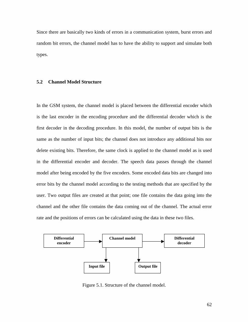
62
Since there are basically two kinds of errors in a communication system, burst errors and
random bit errors, the channel model has to have the ability to support and simulate both
types.
5.2 Channel Model Structure
In the GSM system, the channel model is placed between the differential encoder which
is the last encoder in the encoding procedure and the differential decoder which is the
first decoder in the decoding procedure. In this model, the number of output bits is the
same as the number of input bits; the channel does not introduce any additional bits nor
delete existing bits. Therefore, the same clock is applied to the channel model as is used
in the differential encoder and decoder. The speech data passes through the channel
model after being encoded by the five encoders. Some encoded data bits are changed into
error bits by the channel model according to the testing methods that are specified by the
user. Two output files are created at that point; one file contains the data going into the
channel and the other file contains the data coming out of the channel. The actual error
rate and the positions of errors can be calculated using the data in these two files.
Figure 5.1. Structure of the channel model.
Differential encoder
Channel model Differential decoder
Input file Output file
63
Figure 5.1 shows the placement of the channel model.
5.3 Channel Model Implementation
Our channel model operates in one of two modes: random mode and burst mode. In
random mode, either single bit errors or burst errors are inserted at random locations
based on a user specified error probability. In burst mode, a single burst is inserted at a
specified location.
5.3.1 Random Error Mode
In the random mode, the user needs to specify the error probability, the error duration,
and a “seed” which is an integer value used by the random number generator. The seed
can be any integer with length from 1 to 8 digits. When the channel model is running
under random error mode, each single bit of encoded speech data passing through the
channel has the same probability to become an error bit. The user specifies the
probability that the error happens. The model randomly introduces errors in such a way
that the expected value for a bit error is the user specified probability.
Each data bit read from the encoded speech data stream is a candidate to become an error
bit. The channel model independently decides whether or not each bit will be an error bit.
64
If it decides that the current bit is an error bit, then consecutive error bits will be inserted
as specified by the user selected error duration. Since the decision is random, based on a
statistical distribution, the total error ratio may vary after each simulation but the over all
error ratio will be close to the value of the error probability that the user specified. As the
number of simulations increases, the probability that the average error ratio differs
significantly from the user specified probability decreases.
The user inputs an integer value, PROB, between 0 and MAX, that specifies the desired
probability of an error. The program converts this integer value into an error probability
as follows
MAXPROB ABILITYERROR_PROB =
The current implementation has MAX=10,000. Therefore, if the user inputs 5,000, the
error probability will be
%505.010,0005,000 ABILITYERROR_PROB ===
The smallest non-zero probability of error is therefore
%01.00001.0000,101_____ ===ERROROFPROBZERONONSMALLEST
At the smallest non-zero error rate, 0.01% of the bits will be in error, on average.
The random number functions used in the channel model are provided by the VHDL
IEEE.math_real library. To make those functions visible, the user needs to add “use
IEEE.math_real.all” at the beginning of the VHDL model. GET_RAND_MAX is the
function that returns the maximum random number and RAND is the function generating
a random integer between 0 and GET_RAND_MAX.
65
We now want to compute a point, P, in the random number range so that the probability
that the random number generated is less than or equal to P, is the desired bit error
probability in the channel. The following formula achieves this goal.
MAXRANDMAXPROBMAXRANDYPROBABILITERRORP _*_*_ ==
To determine whether a bit error should occur, we generate a random number, R, in the
range (0 to RAND_MAX). If R<P, an error occurs. If R≥P, no error occurs.
As currently implemented, the minimum non-zero error probability is 0.0001 (0.01%).
This minimum can be reduced by selecting a different value for MAX. For example, if
MAX=100,000, then the minimum non-zero probability of error is: 1/100,000=0.00001
(0.001%).
The minimum non-zero probability is limited by the range of random numbers generated
by the VHDL random number generator. In our system, RAND_MAX is a ten digits
integer. To optimize accuracy, MAX should be ≤ RAND_MAX. A lower bound on the
minimum non-zero probability of error is: 1/RAND_MAX.
The VHDL model shown below implements the above algorithm.
R:=RAND; -- call random number function to generate a random number-- P=random/10000*PROB for 0.01% error rate-- P=random/100000*PROB for 0.001% rate-- etc...P := PROB*GET_RAND_MAX/10000;if R<P then
-- there is a bit errorelse
-- there is no error
66
“R” is a random number created by the computer. “PROB” is the user input error
probability explained above. “GET_RAND_MAX” function will return a constant integer
which indicates the maximum value of the random number created by the computer. So,
the actual range of R described above is 0≤R≤GET_RAND_MAX.
To create a random number, the user needs to input an initial seed, which is used to
initialize the random number generation process. This is important to ensure repeatable
simulation results. The user can repeat the simulation by using the same initial seed.
Furthermore, the seed can be any positive integer up to eight digits. This makes it
possible to have millions of different test sequences.
The other required user input variable is the error duration. For random bit errors, the
error duration is set to 1 to ensure that the overall error probability matches the user’s
input single bit error probability. For example, if the user specifies that the single bit error
probability is 5% and the error duration is 1 bit, then the overall system error ratio is 5%;
For burst errors, the user specifies both the desired burst probability and the burst
duration. For example, if the user specifies a burst probability of 0.05 (5%) and a duration
of 2 bits, then non-overlapping two bit burst errors will be inserted at 5% of the locations
in the data stream.
5.3.2 Burst Error Mode
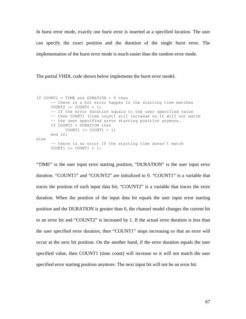
67
In burst error mode, exactly one burst error is inserted at a specified location. The user
can specify the exact position and the duration of the single burst error. The
implementation of the burst error mode is much easier than the random error mode.
The partial VHDL code shown below implements the burst error model.
if COUNT1 = TIME and DURATION > 0 then-- there is a bit error happen is the starting time matchesCOUNT2 := COUNT2 + 1;-- if the error duration equals to the user specified value-- then COUNT1 (time count) will increase so it will not match-- the user specified error starting position anymore.if COUNT2 = DURATION then
COUNT1 := COUNT1 + 1;end if;
else-- there is no error if the starting time doesn’t matchCOUNT1 := COUNT1 + 1;
“TIME” is the user input error starting position, “DURATION” is the user input error
duration. “COUNT1” and “COUNT2” are initialized to 0. “COUNT1” is a variable that
traces the position of each input data bit; “COUNT2” is a variable that traces the error
duration. When the position of the input data bit equals the user input error starting
position and the DURATION is greater than 0, the channel model changes the current bit
to an error bit and “COUNT2” is increased by 1. If the actual error duration is less than
the user specified error duration, then “COUNT1” stops increasing so that an error will
occur at the next bit position. On the another hand, if the error duration equals the user
specified value, then COUNT1 (time count) will increase so it will not match the user
specified error starting position anymore. The next input bit will not be an error bit.
68
5.4 Channel Model Validation
To validate the channel model, a sequence of tests were done by comparing the
output data stream with the input data stream in order to calculate the actual error
probability during the testing. The different testing parameters such as the error
probability, error duration and the initial seed were applied during each test. The
testing result is shown below.
• = Random Error Mode
The random error mode test was repeated 100 times to calculate the average error
probability. An error probability distribution diagram was produced using Matlab.
Refer to Appendix F (testbench file) and Appendix E (C control file).
Testing parameters from testbench:
The input error probability (PROB) is: 500 (Corresponding to an expected error
probability of 0.05 (5.0%))
The input error duration (DUR) is: 1
The input initial seed: 55555
The simulation loop repeats 100 times to calculate the average error probability.
The actual user specified error probability is 500*0.01%=5.0%. The log file of the
simulation is shown in Appendix D. The average single bit error probability for
the 100 runs was 5.003% with a standard deviation of 0.7131. The error
distribution diagram is shown in Figure 5.2.
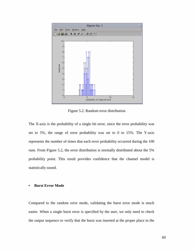
69
Figure 5.2. Random error distribution.
The X-axis is the probability of a single bit error, since the error probability was
set to 5%, the range of error probability was set to 0 to 15%. The Y-axis
represents the number of times that each error probability occurred during the 100
runs. From Figure 5.2, the error distribution is normally distributed about the 5%
probability point. This result provides confidence that the channel model is
statistically sound.
• = Burst Error Mode
Compared to the random error mode, validating the burst error mode is much
easier. When a single burst error is specified by the user, we only need to check
the output sequence to verify that the burst was inserted at the proper place in the
70
output sequence. For example, when the user specified error starting time was 50
and the error duration was 10, a single burst error with duration 10 started from
the 50th clock cycle and lasted for 10 clock cycles. This was verified by manually
examining the output file.
71
Chapter 6. Implementation of the User Interface
A C program is used to implement the user interface for the testing system. The program
controls the details of the simulation, compares the data and outputs the test results.
6.1 Overview
The GSM encoder, decoder and channel models were written in VHDL and need special
software to compile and simulate them. Synopsys is a very popular tool for compiling,
debugging and simulating VHDL source code based on the UNIX operating system.
To allow a user that does not understand the details of VHDL to use the models, a
program was written in the C language to control simulation. The source code is provided
in Appendix E.
72
6.2 Approach
As soon as the user starts the control program, the program asks the user to input data
such as desired error mode, the probability and the duration of errors, the seed, etc. It also
requires the user to choose a testbench template and to specify how many times the
simulation is to be repeated.
Another C program is used to compare the original speech data stream before encoding
and the received data stream after decoding .
After the user inputs the necessary parameters for the simulation, the system control
program starts Synopsys, compile all the VHDL models, and starts the simulation
process. The compare program is called automatically after each simulation to analyze
the output data. The test result is displayed on the screen and output to a record file. The
rest of this chapter states the results derived from a set of tests and discusses the overall
system performance.
6.3 Template Test bench Generation
Testbench Pro, a product by Synapticad, generates the template test benches. Testbench
Pro provides a friendly graphical user interface to create clocks and input/output signals.
It allows the user to define mathematical equations to create a long sequence of data
values. The details of creating template test benches is explained below.
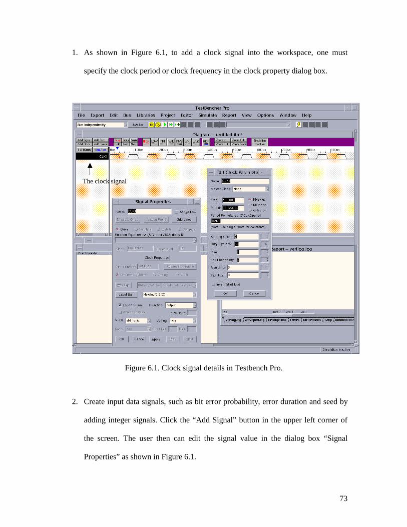
73
1. As shown in Figure 6.1, to add a clock signal into the workspace, one must
specify the clock period or clock frequency in the clock property dialog box.
Figure 6.1. Clock signal details in Testbench Pro.
2. Create input data signals, such as bit error probability, error duration and seed by
adding integer signals. Click the “Add Signal” button in the upper left corner of
the screen. The user then can edit the signal value in the dialog box “Signal
Properties” as shown in Figure 6.1.
The clock signal
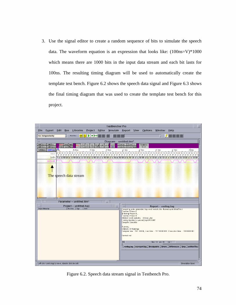
74
3. Use the signal editor to create a random sequence of bits to simulate the speech
data. The waveform equation is an expression that looks like: (100ns=V)*1000
which means there are 1000 bits in the input data stream and each bit lasts for
100ns. The resulting timing diagram will be used to automatically create the
template test bench. Figure 6.2 shows the speech data signal and Figure 6.3 shows
the final timing diagram that was used to create the template test bench for this
project.
Figure 6.2. Speech data stream signal in Testbench Pro.
The speech data stream
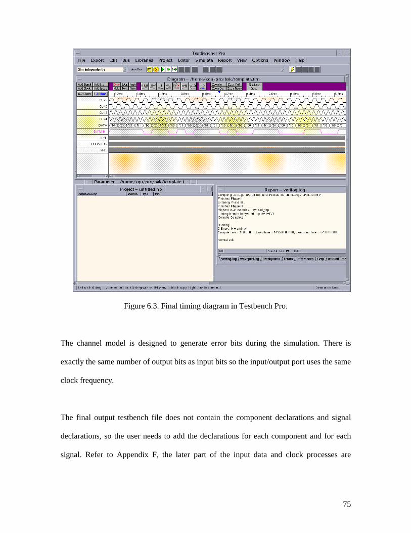
75
Figure 6.3. Final timing diagram in Testbench Pro.
The channel model is designed to generate error bits during the simulation. There is
exactly the same number of output bits as input bits so the input/output port uses the same
clock frequency.
The final output testbench file does not contain the component declarations and signal
declarations, so the user needs to add the declarations for each component and for each
signal. Refer to Appendix F, the later part of the input data and clock processes are
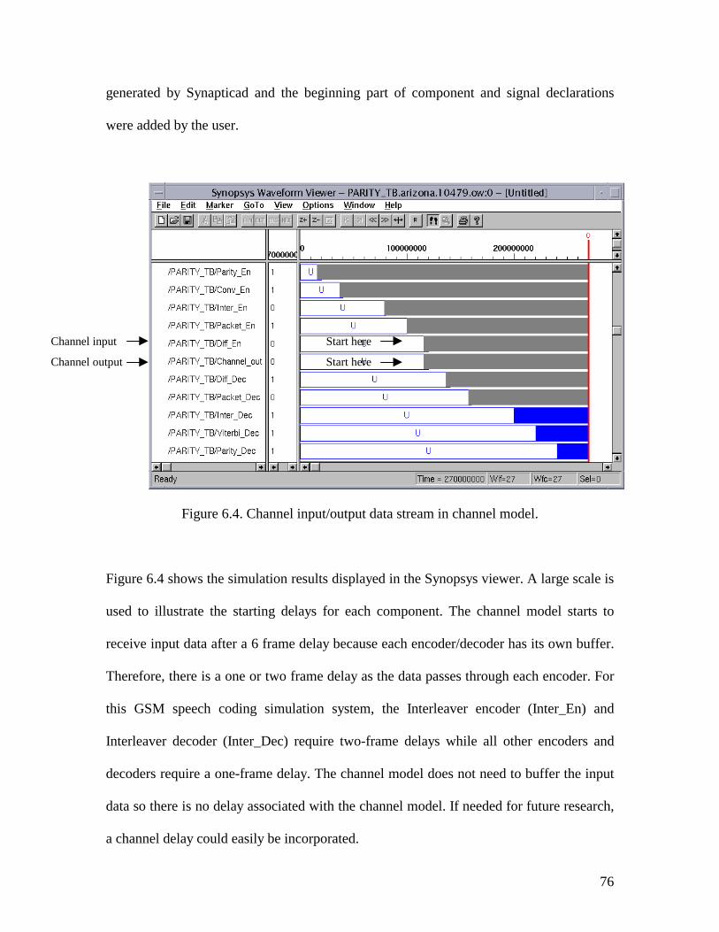
76
generated by Synapticad and the beginning part of component and signal declarations
were added by the user.
Figure 6.4. Channel input/output data stream in channel model.
Figure 6.4 shows the simulation results displayed in the Synopsys viewer. A large scale is
used to illustrate the starting delays for each component. The channel model starts to
receive input data after a 6 frame delay because each encoder/decoder has its own buffer.
Therefore, there is a one or two frame delay as the data passes through each encoder. For
this GSM speech coding simulation system, the Interleaver encoder (Inter_En) and
Interleaver decoder (Inter_Dec) require two-frame delays while all other encoders and
decoders require a one-frame delay. The channel model does not need to buffer the input
data so there is no delay associated with the channel model. If needed for future research,
a channel delay could easily be incorporated.
Channel input
Channel output
Start here
Start here
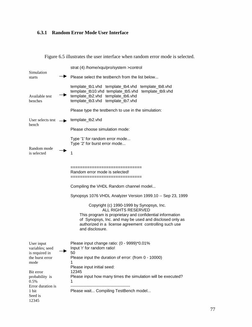
77
6.3.1 Random Error Mode User Interface
Figure 6.5 illustrates the user interface when random error mode is selected.
strat (4) /home/xqu/pro/system >control Please select the testbench from the list below... template_tb1.vhd template_tb4.vhd template_tb8.vhd template_tb10.vhd template_tb5.vhd template_tb9.vhd template_tb2.vhd template_tb6.vhd template_tb3.vhd template_tb7.vhd Please type the testbench to use in the simulation: template_tb2.vhd Please choose simulation mode: Type '1' for random error mode... Type '2' for burst error mode... 1 ============================== Random error mode is selected! ============================== Compiling the VHDL Random channel model... Synopsys 1076 VHDL Analyzer Version 1999.10 -- Sep 23, 1999 Copyright (c) 1990-1999 by Synopsys, Inc. ALL RIGHTS RESERVED This program is proprietary and confidential information of Synopsys, Inc. and may be used and disclosed only as authorized in a license agreement controlling such use and disclosure. Please input change ratio: (0 - 9999)*0.01% Input 'r' for random ratio! 50 Please input the duration of error: (from 0 - 10000) 1 Please input initial seed: 12345 Please input how many times the simulation will be executed? 1 ------------------------------------------- Please wait... Compiling TestBench model...
Simulation starts Available test benches User selects test bench Random mode is selected User input variables; seed is required in the burst error mode Bit error probability is 0.5% Error duration is 1 bit Seed is 12345
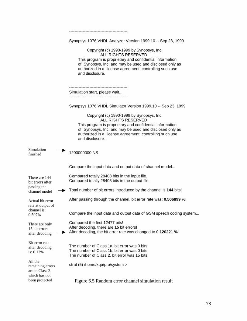
78
------------------------------------------- Synopsys 1076 VHDL Analyzer Version 1999.10 -- Sep 23, 1999 Copyright (c) 1990-1999 by Synopsys, Inc. ALL RIGHTS RESERVED This program is proprietary and confidential information of Synopsys, Inc. and may be used and disclosed only as authorized in a license agreement controlling such use and disclosure. ------------------------------------------- Simulation start, please wait... ------------------------------------------- Synopsys 1076 VHDL Simulator Version 1999.10 -- Sep 23, 1999 Copyright (c) 1990-1999 by Synopsys, Inc. ALL RIGHTS RESERVED This program is proprietary and confidential information of Synopsys, Inc. and may be used and disclosed only as authorized in a license agreement controlling such use and disclosure. 1200000000 NS Compare the input data and output data of channel model... Compared totally 28408 bits in the input file. Compared totally 28408 bits in the output file. Total number of bit errors introduced by the channel is 144 bits! After passing through the channel, bit error rate was: 0.506899 %! Compare the input data and output data of GSM speech coding system... Compared the first 12477 bits! After decoding, there are 15 bit errors! After decoding, the bit error rate was changed to 0.120221 %! The number of Class 1a. bit error was 0 bits. The number of Class 1b. bit error was 0 bits. The number of Class 2. bit error was 15 bits. strat (5) /home/xqu/pro/system >
Figure 6.5 Random error channel simulation result
Simulation finished There are 144 bit errors after passing the channel model Actual bit error rate at output of channel is: 0.507% There are only 15 bit errors after decoding Bit error rate after decoding is: 0.12% All the remaining errors are in Class 2 which has not been protected
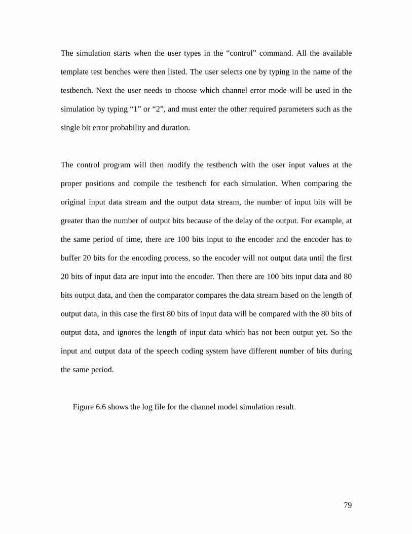
79
The simulation starts when the user types in the “control” command. All the available
template test benches were then listed. The user selects one by typing in the name of the
testbench. Next the user needs to choose which channel error mode will be used in the
simulation by typing “1” or “2”, and must enter the other required parameters such as the
single bit error probability and duration.
The control program will then modify the testbench with the user input values at the
proper positions and compile the testbench for each simulation. When comparing the
original input data stream and the output data stream, the number of input bits will be
greater than the number of output bits because of the delay of the output. For example, at
the same period of time, there are 100 bits input to the encoder and the encoder has to
buffer 20 bits for the encoding process, so the encoder will not output data until the first
20 bits of input data are input into the encoder. Then there are 100 bits input data and 80
bits output data, and then the comparator compares the data stream based on the length of
output data, in this case the first 80 bits of input data will be compared with the 80 bits of
output data, and ignores the length of input data which has not been output yet. So the
input and output data of the speech coding system have different number of bits during
the same period.
Figure 6.6 shows the log file for the channel model simulation result.
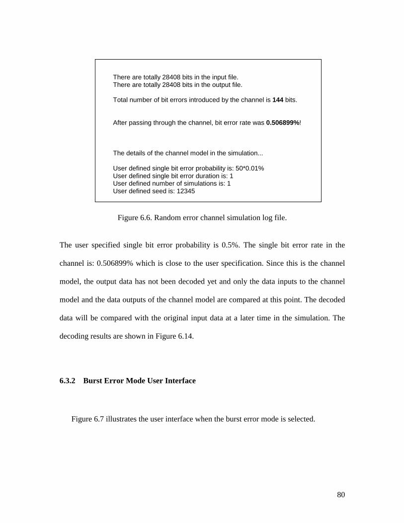
80
There are totally 28408 bits in the input file. There are totally 28408 bits in the output file. Total number of bit errors introduced by the channel is 144 bits. After passing through the channel, bit error rate was 0.506899%! The details of the channel model in the simulation... User defined single bit error probability is: 50*0.01% User defined single bit error duration is: 1 User defined number of simulations is: 1 User defined seed is: 12345
Figure 6.6. Random error channel simulation log file.
The user specified single bit error probability is 0.5%. The single bit error rate in the
channel is: 0.506899% which is close to the user specification. Since this is the channel
model, the output data has not been decoded yet and only the data inputs to the channel
model and the data outputs of the channel model are compared at this point. The decoded
data will be compared with the original input data at a later time in the simulation. The
decoding results are shown in Figure 6.14.
6.3.2 Burst Error Mode User Interface
Figure 6.7 illustrates the user interface when the burst error mode is selected.
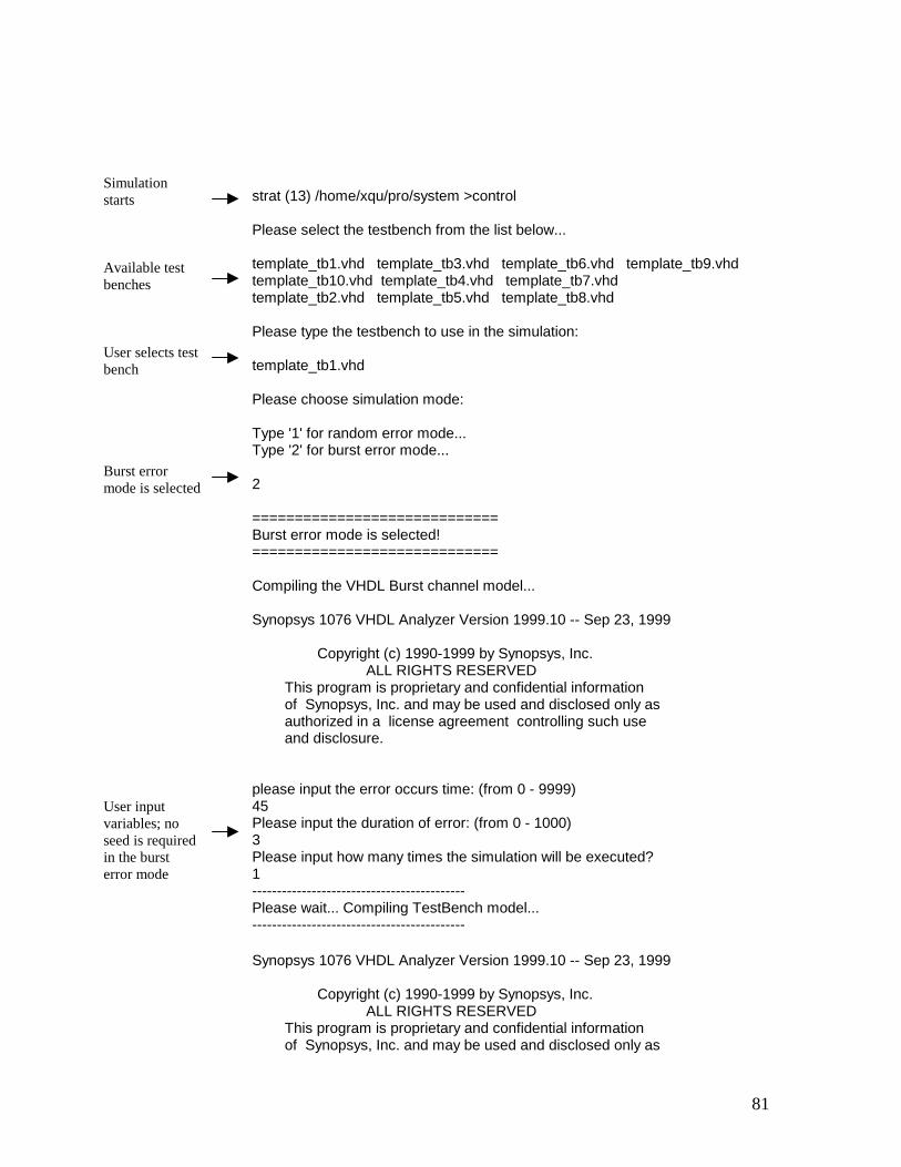
strat (13) /home/xqu/pro/system >control Please select the testbench from the list below... template_tb1.vhd template_tb3.vhd template_tb6.vhd template_tb9.vhd template_tb10.vhd template_tb4.vhd template_tb7.vhd template_tb2.vhd template_tb5.vhd template_tb8.vhd Please type the testbench to use in the simulation: template_tb1.vhd Please choose simulation mode: Type '1' for random error mode... Type '2' for burst error mode... 2
Simulation starts Available test benches User selects test bench Burst error mode is selected
============================= Burst error mode is selected! ============================= Compiling the VHDL Burst channel model... Synopsys 1076 VHDL Analyzer Version 1999.10 -- Sep 23, 1999 Copyright (c) 1990-1999 by Synopsys, Inc. ALL RIGHTS RESERVED This program is proprietary and confidential information of Synopsys, Inc. and may be used and disclosed only as authorized in a license agreement controlling such use and disclosure. please input the error occurs time: (from 0 - 9999) 45 Please input the duration of error: (from 0 - 1000) 3 Please input how many times the simulation will be executed? 1 ------------------------------------------- Please wait... Compiling TestBench model...
User input variables; no seed is required in the burst error mode
81
------------------------------------------- Synopsys 1076 VHDL Analyzer Version 1999.10 -- Sep 23, 1999 Copyright (c) 1990-1999 by Synopsys, Inc. ALL RIGHTS RESERVED This program is proprietary and confidential information of Synopsys, Inc. and may be used and disclosed only as
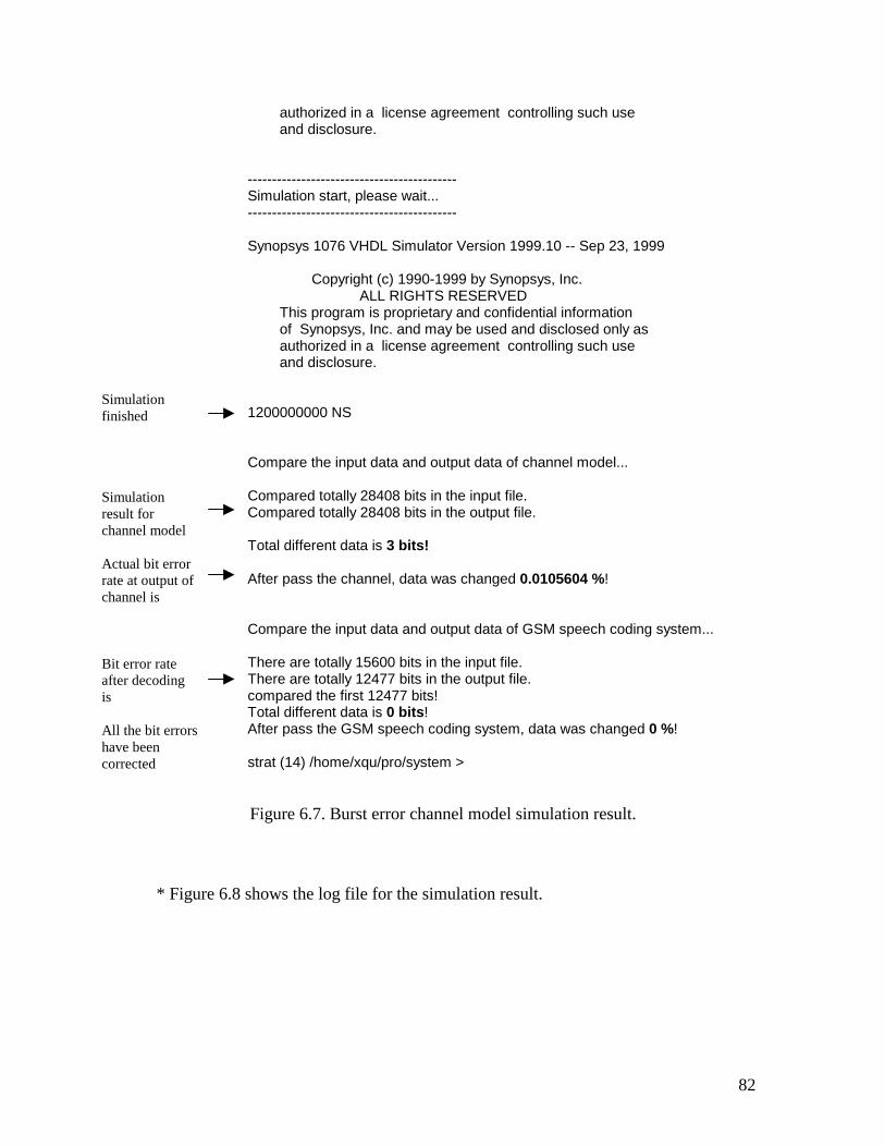
authorized in a license agreement controlling such use and disclosure. ------------------------------------------- Simulation start, please wait... ------------------------------------------- Synopsys 1076 VHDL Simulator Version 1999.10 -- Sep 23, 1999 Copyright (c) 1990-1999 by Synopsys, Inc. ALL RIGHTS RESERVED This program is proprietary and confidential information of Synopsys, Inc. and may be used and disclosed only as authorized in a license agreement controlling such use and disclosure. 1200000000 NS Compare the input data and output data of channel model... Compared totally 28408 bits in the input file. Compared totally 28408 bits in the output file. Total different data is 3 bits! After pass the channel, data was changed 0.0105604 %! Compare the input data and output data of GSM speech coding system... There are totally 15600 bits in the input file. There are totally 12477 bits in the output file. compared the first 12477 bits! Total different data is 0 bits! After pass the GSM speech coding system, data was changed 0 %! strat (14) /home/xqu/pro/system >
Simulation result for channel model Actual bit error rate at output of channel is Bit error rate after decoding is All the bit errors have been corrected
Simulation finished
82
Figure 6.7. Burst error channel model simulation result.
* Figure 6.8 shows the log file for the simulation result.
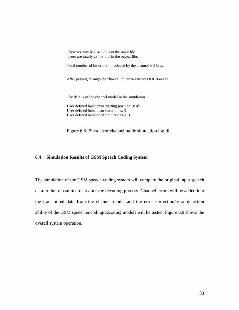
83
There are totally 28408 bits in the input file. There are totally 28408 bits in the output file. Total number of bit errors introduced by the channel is 3 bits. After passing through the channel, bit error rate was 0.010560%! The details of the channel model in the simulation... User defined burst error starting position is: 45 User defined burst error duration is: 3 User defined number of simulations is: 1
Figure 6.8. Burst error channel mode simulation log file.
6.4 Simulation Results of GSM Speech Coding System
The simulation of the GSM speech coding system will compare the original input speech
data to the transmitted data after the decoding process. Channel errors will be added into
the transmitted data from the channel model and the error correction/error detection
ability of the GSM speech encoding/decoding models will be tested. Figure 6.9 shows the
overall system operation.
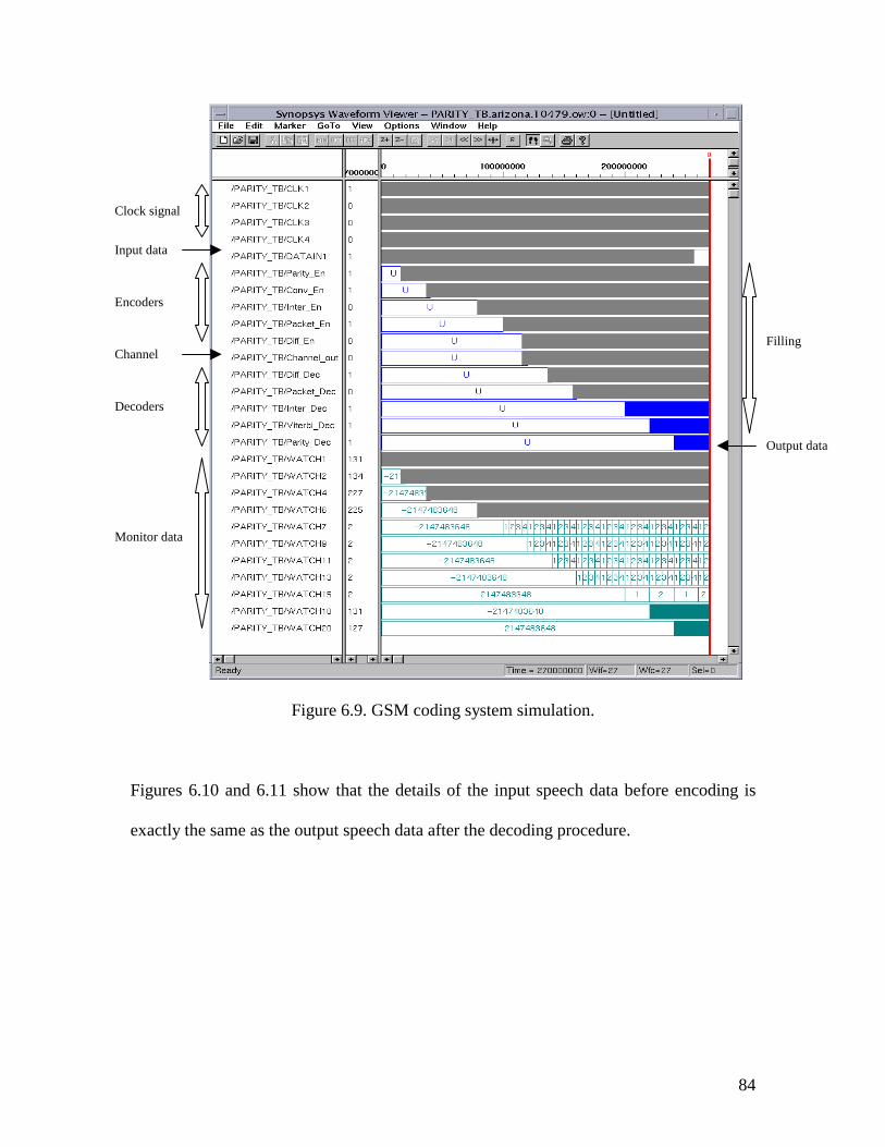
84
Figure 6.9. GSM coding system simulation.
Figures 6.10 and 6.11 show that the details of the input speech data before encoding is
exactly the same as the output speech data after the decoding procedure.
Clock signal
Encoders
Decoders
Monitor data
Channel
Input data
Filling
Output data
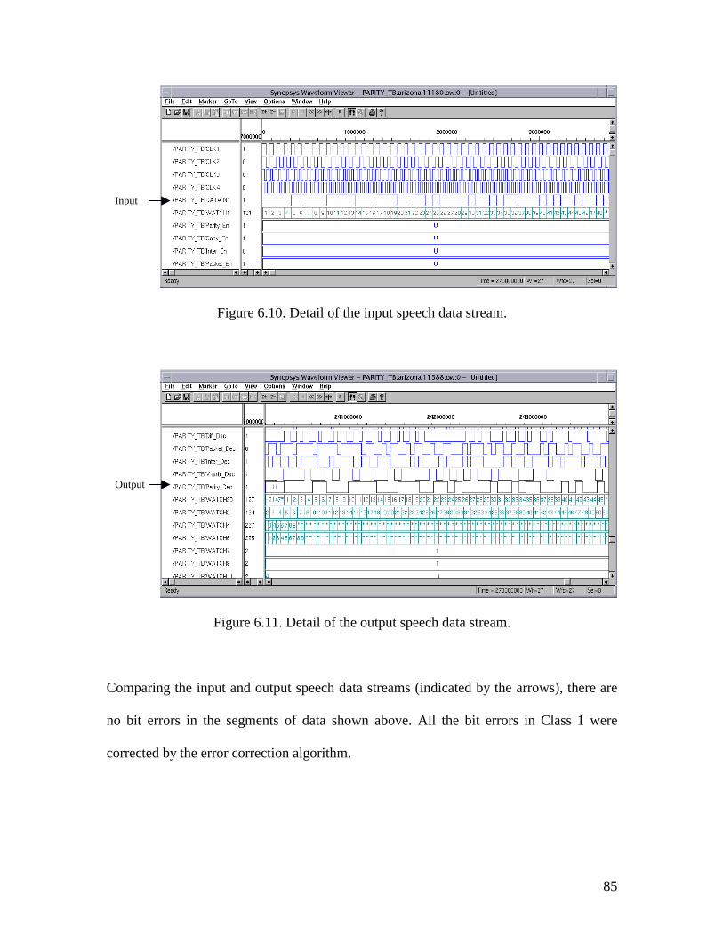
85
Figure 6.10. Detail of the input speech data stream.
Figure 6.11. Detail of the output speech data stream.
Comparing the input and output speech data streams (indicated by the arrows), there are
no bit errors in the segments of data shown above. All the bit errors in Class 1 were
corrected by the error correction algorithm.
Input
Output
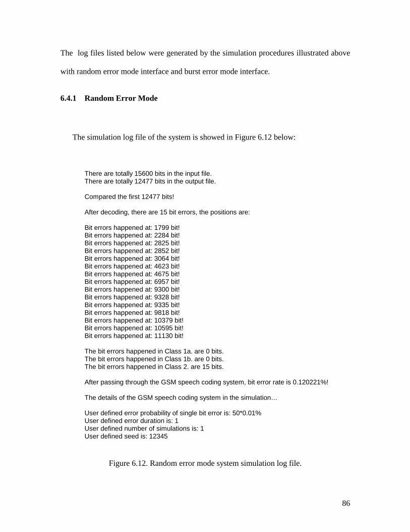
86
The log files listed below were generated by the simulation procedures illustrated above
with random error mode interface and burst error mode interface.
6.4.1 Random Error Mode
The simulation log file of the system is showed in Figure 6.12 below:
There are totally 15600 bits in the input file. There are totally 12477 bits in the output file. Compared the first 12477 bits! After decoding, there are 15 bit errors, the positions are: Bit errors happened at: 1799 bit! Bit errors happened at: 2284 bit! Bit errors happened at: 2825 bit! Bit errors happened at: 2852 bit! Bit errors happened at: 3064 bit! Bit errors happened at: 4623 bit! Bit errors happened at: 4675 bit! Bit errors happened at: 6957 bit! Bit errors happened at: 9300 bit! Bit errors happened at: 9328 bit! Bit errors happened at: 9335 bit! Bit errors happened at: 9818 bit! Bit errors happened at: 10379 bit! Bit errors happened at: 10595 bit! Bit errors happened at: 11130 bit! The bit errors happened in Class 1a. are 0 bits. The bit errors happened in Class 1b. are 0 bits. The bit errors happened in Class 2. are 15 bits. After passing through the GSM speech coding system, bit error rate is 0.120221%! The details of the GSM speech coding system in the simulation… User defined error probability of single bit error is: 50*0.01% User defined error duration is: 1 User defined number of simulations is: 1 User defined seed is: 12345
Figure 6.12. Random error mode system simulation log file.
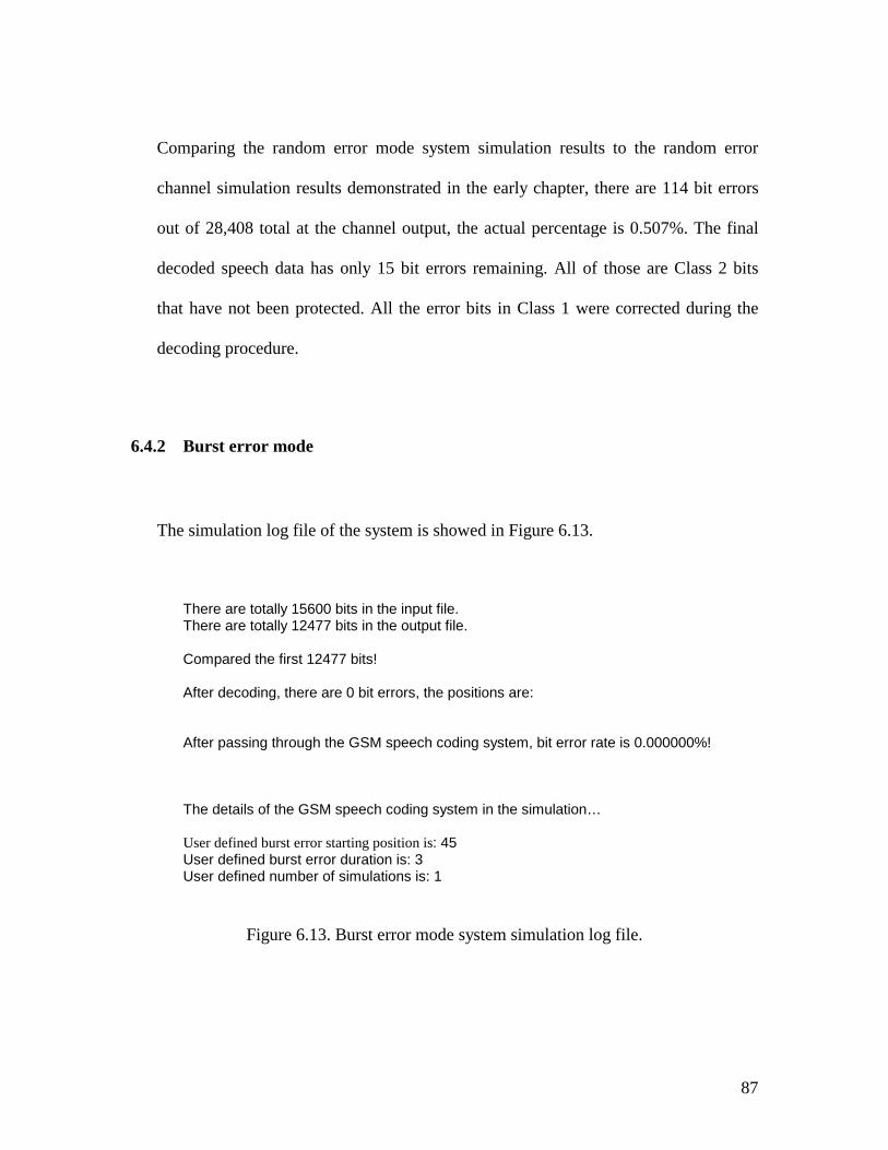
87
Comparing the random error mode system simulation results to the random error
channel simulation results demonstrated in the early chapter, there are 114 bit errors
out of 28,408 total at the channel output, the actual percentage is 0.507%. The final
decoded speech data has only 15 bit errors remaining. All of those are Class 2 bits
that have not been protected. All the error bits in Class 1 were corrected during the
decoding procedure.
6.4.2 Burst error mode
The simulation log file of the system is showed in Figure 6.13.
There are totally 15600 bits in the input file. There are totally 12477 bits in the output file. Compared the first 12477 bits! After decoding, there are 0 bit errors, the positions are: After passing through the GSM speech coding system, bit error rate is 0.000000%! The details of the GSM speech coding system in the simulation… User defined burst error starting position is: 45 User defined burst error duration is: 3 User defined number of simulations is: 1
Figure 6.13. Burst error mode system simulation log file.
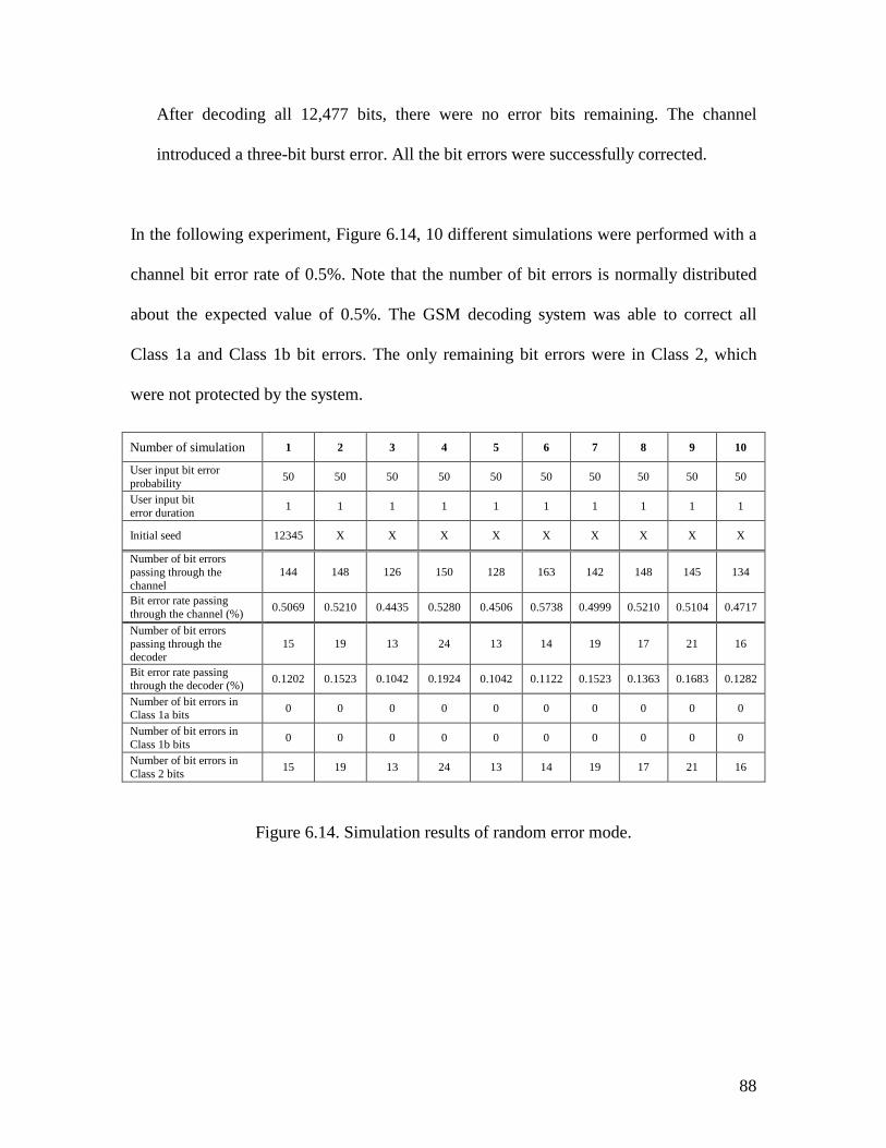
88
After decoding all 12,477 bits, there were no error bits remaining. The channel
introduced a three-bit burst error. All the bit errors were successfully corrected.
In the following experiment, Figure 6.14, 10 different simulations were performed with a
channel bit error rate of 0.5%. Note that the number of bit errors is normally distributed
about the expected value of 0.5%. The GSM decoding system was able to correct all
Class 1a and Class 1b bit errors. The only remaining bit errors were in Class 2, which
were not protected by the system.
Figure 6.14. Simulation results of random error mode.
Number of simulation 1 2 3 4 5 6 7 8 9 10
User input bit error probability 50 50 50 50 50 50 50 50 50 50
User input bit error duration 1 1 1 1 1 1 1 1 1 1
Initial seed 12345 X X X X X X X X X
Number of bit errors passing through the channel
144 148 126 150 128 163 142 148 145 134
Bit error rate passing through the channel (%) 0.5069 0.5210 0.4435 0.5280 0.4506 0.5738 0.4999 0.5210 0.5104 0.4717
Number of bit errors passing through the decoder
15 19 13 24 13 14 19 17 21 16
Bit error rate passing through the decoder (%) 0.1202 0.1523 0.1042 0.1924 0.1042 0.1122 0.1523 0.1363 0.1683 0.1282
Number of bit errors in Class 1a bits 0 0 0 0 0 0 0 0 0 0
Number of bit errors in Class 1b bits 0 0 0 0 0 0 0 0 0 0
Number of bit errors in Class 2 bits 15 19 13 24 13 14 19 17 21 16
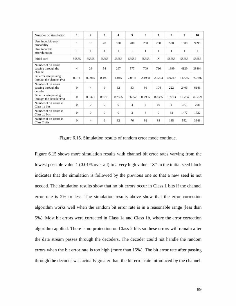
89
Figure 6.15. Simulation results of random error mode continue.
Figure 6.15 shows more simulation results with channel bit error rates varying from the
lowest possible value 1 (0.01% over all) to a very high value. “X” in the initial seed block
indicates that the simulation is followed by the previous one so that a new seed is not
needed. The simulation results show that no bit errors occur in Class 1 bits if the channel
error rate is 2% or less. The simulation results above show that the error correction
algorithm works well when the random bit error rate is in a reasonable range (less than
5%). Most bit errors were corrected in Class 1a and Class 1b, where the error correction
algorithm applied. There is no protection on Class 2 bits so these errors will remain after
the data stream passes through the decoders. The decoder could not handle the random
errors when the bit error rate is too high (more than 15%). The bit error rate after passing
through the decoder was actually greater than the bit error rate introduced by the channel.
Number of simulation 1 2 3 4 5 6 7 8 9 10
User input bit error probability 1 10 20 100 200 250 250 500 1500 9999
User input bit error duration 1 1 1 1 1 1 1 1 1 1
Initial seed 55555 55555 55555 55555 55555 55555 X 55555 55555 55555
Number of bit errors passing through the channel
4 26 54 297 577 709 716 1399 4129 28404
Bit error rate passing through the channel (%) 0.014 0.0915 0.1901 1.045 2.0311 2.4958 2.5204 4.9247 14.535 99.986
Number of bit errors passing through the decoder
0 4 9 32 83 99 104 222 2406 6146
Bit error rate passing through the decoder (%) 0 0.0321 0.0721 0.2565 0.6652 0.7935 0.8335 1.7793 19.284 49.259
Number of bit errors in Class 1a bits 0 0 0 0 4 4 16 4 377 768
Number of bit errors in Class 1b bits 0 0 0 0 3 3 0 33 1477 1732
Number of bit errors in Class 2 bits 0 4 9 32 76 92 88 185 552 3646
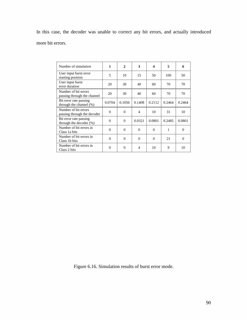
90
In this case, the decoder was unable to correct any bit errors, and actually introduced
more bit errors.
Figure 6.16. Simulation results of burst error mode.
Number of simulation 1 2 3 4 5 6
User input burst error starting position 5 10 15 50 100 50
User input burst error duration 20 30 40 60 70 70
Number of bit errors passing through the channel 20 30 40 60 70 70
Bit error rate passing through the channel (%) 0.0704 0.1056 0.1408 0.2112 0.2464 0.2464
Number of bit errors passing through the decoder 0 0 4 10 31 10
Bit error rate passing through the decoder (%) 0 0 0.0321 0.0801 0.2485 0.0801
Number of bit errors in Class 1a bits 0 0 0 0 1 0
Number of bit errors in Class 1b bits 0 0 0 0 21 0
Number of bit errors in Class 2 bits 0 0 4 10 9 10
91
The simulation results in Figure 6.16 indicate that the error correction algorithm works
well when the burst error is a reasonable length (less than 60 bits). Most bit errors were
corrected in Class 1a and Class 1b, where the error correction algorithm is applied. There
is no protection on Class 2 bits, so these errors remain after the data stream passes
through the decoders. The decoder could not handle one burst error with length = 70 bits.
The bit error rate after passing through the decoder was actually greater than the bit error
rate introduced by the channel. In this case, the decoder was unable to correct the bit
errors. The latent errors persisted for a while in the decoder.
92
Chapter 7. Smnnary
This thesis discusses a methodology for behavioral test bench generation for
communication systems. A flexible channel model was developed to generate bit errors
specified by the user. A GSM cellular phone speech data coding system VHDL model
was built to illustrate the methodology. A part of the intelligent user interface has been
developed to accept user’s input parameters, create final test benches and control the
system simulation procedure. A stream data comparator was developed to process the
large amount of speech data after the simulation and calculate performance statistics.
Some future work might improve or expand the work reported here. The intelligent user
interface could be integrated into the goal-based testbench generation system being
developed at Virginia Tech under NSF support. There may be other methods to create
template test benches so that there is no need for manual modification of the template test
benches generated by Testbench Pro such as the declaration of components mentioned in
Chapter 6.
93
References
[1] D. Smith, HDL Chip Design: A Practical Guide for Designing, Synthesizing, and
Simulating ASICs and FPGAs Using VHDL or Verilog. Madison AL: Doone, 1996.
[2] Janick Bergeron, Writing Testbenches Functional Verification of HDL Models, Kluwer
Academic Publishers, 2000, pp. 159-167.
[3] Siegmund M. Redl, Matthias K. weber, Malcolm W. Oliphant, An introduction to GSM,
Artech House Publishers, 1995, pp. 1-16.
[4] J.R. Armstrong, G. Frank, S. Hrishikesh, P. Gowrisankaran, and Z. Xu, “Test Bench
Development for RASSP DSP Models,” in Proc. 1st Annu. RASSP Conf., Arlington, VA,
August 1994, pp. 91-96.
[5] J.R. Armstrong, G. Frank, and F.G. Gray, “High-Level Generation of VHDL Test
Benches,” in Proc. Spring VHDL Int. Users Forum, April 1995, pp. 6.23-6.34.
[6] J.R. Armstrong, G.A. Frank, and F.G. Gray, “Efficient Approaches to Testing VHDL
DSP Models,” J. VSLI Signal Processing, vol. 14. pp. 221-234, November 1996.
[7] Stephen B. Wicker, Error Control Systems for Digital Communication and Storage,
Prentice Hall, 1995, pp. 92-114.
94
[8] D.M. Balston, R.V. Macario, “Cellular Radio Systems”, Boston: Artech House, 1993, pp.
53-80.
[9] Lawrence Harte, Richard Levine, and Geoff Livingston, “GSM Superphones”, New
York: McGraw-Hill, 1999, pp. 63-65.
[10] M. Budagavi and J.D. Gibson, "Speech Coding in Mobile Radio Communications,"
Proceedings of the IEEE, Vol. 86, No. 7, 1998.
[11] Michael Mouly, Marie-Bernadette Pautet, “The GSM System for Mobile
Communications”, 1995, pp. 73-97.
[12] Peter Wong and David Britland, “Mobile data communications systems”, Boston, Artech
House, 1993, pp. 79-101.
[13] Asha Mehrotra, “GSM System Engineering”, Boston: Artech House, 1997, pp 193-195,
pp. 200-202.
[14] Siegmund M. Redl, Matthias K. Weber and Malcolm W. Oliphant, “An Introduction to
GSM”, Boston: Artech House, 1995, pp. 112-120.
[15] Dietmar Kopitz and Bev Marks, “RDS: The radio data system”, Boston, Artech House,
1994, pp. 90-119.
[16] Gunnar Heine, “GSM Networks: Protocols, Terminology, and Implementation”, Boston,
Mass. : Artech House, 1998, pp. 132-155.
[17] A. J. Viterbi, “Convolutional Codes and Their Performance in Communication Systems”,
Addison-Wesley Pub, October 1971, pp. 139-168.
[18] J. (Jorg) Eberspacher, “GSM Switching, Services, and Protocol”, Chichester; New York:
Wiley, 1999, pp. 111-154.
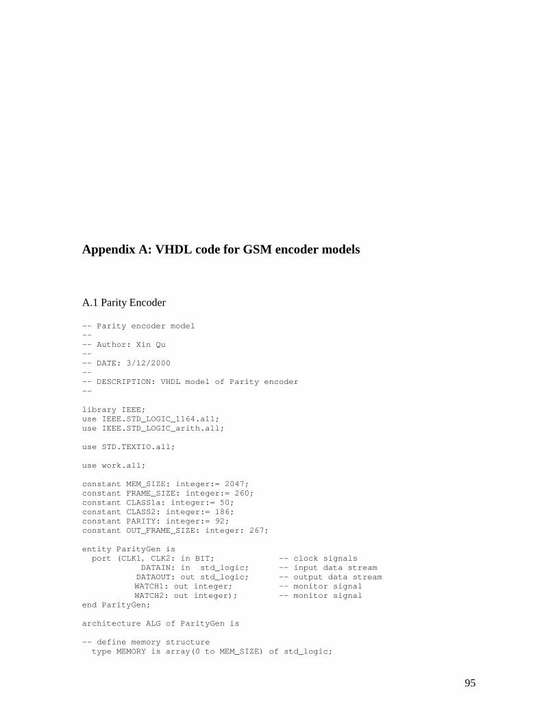
95
Appendix A: VHDL code for GSM encoder models
A.1 Parity Encoder
-- Parity encoder model---- Author: Xin Qu---- DATE: 3/12/2000---- DESCRIPTION: VHDL model of Parity encoder--
library IEEE;use IEEE.STD_LOGIC_1164.all;use IEEE.STD_LOGIC_arith.all;
use STD.TEXTIO.all;
use work.all;
constant MEM_SIZE: integer:= 2047;constant FRAME_SIZE: integer:= 260;constant CLASS1a: integer:= 50;constant CLASS2: integer:= 186;constant PARITY: integer:= 92;constant OUT_FRAME_SIZE: integer: 267;
entity ParityGen isport (CLK1, CLK2: in BIT; -- clock signals
DATAIN: in std_logic; -- input data streamDATAOUT: out std_logic; -- output data streamWATCH1: out integer; -- monitor signalWATCH2: out integer); -- monitor signal
end ParityGen;
architecture ALG of ParityGen is
-- define memory structuretype MEMORY is array(0 to MEM_SIZE) of std_logic;
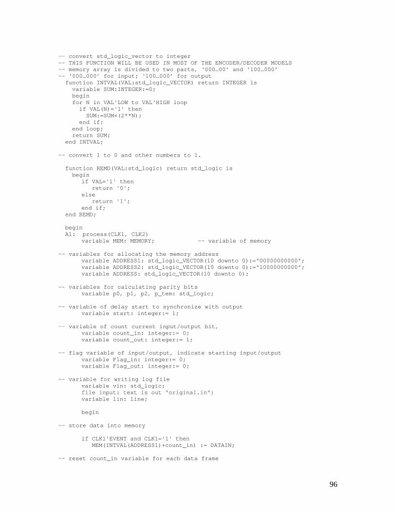
96
-- convert std_logic_vector to integer-- THIS FUNCTION WILL BE USED IN MOST OF THE ENCODER/DECODER MODELS-- memory array is divided to two parts, ‘000…00’ and ‘100…000’-- ‘000…000’ for input; ‘100…000’ for output
function INTVAL(VAL:std_logic_VECTOR) return INTEGER isvariable SUM:INTEGER:=0;beginfor N in VAL'LOW to VAL'HIGH loop
if VAL(N)='1' thenSUM:=SUM+(2**N);
end if;end loop;return SUM;
end INTVAL;
-- convert 1 to 0 and other numbers to 1.
function REMD(VAL:std_logic) return std_logic isbegin
if VAL='1' thenreturn '0';
elsereturn '1';
end if;end REMD;
beginA1: process(CLK1, CLK2)
variable MEM: MEMORY; -- variable of memory
-- variables for allocating the memory addressvariable ADDRESS1: std_logic_VECTOR(10 downto 0):="00000000000";variable ADDRESS2: std_logic_VECTOR(10 downto 0):="10000000000";variable ADDRESS: std_logic_VECTOR(10 downto 0);
-- variables for calculating parity bitsvariable p0, p1, p2, p_tem: std_logic;
-- variable of delay start to synchronize with outputvariable start: integer:= 1;
-- variable of count current input/output bit,variable count_in: integer:= 0;variable count_out: integer:= 1;
-- flag variable of input/output, indicate starting input/outputvariable Flag_in: integer:= 0;variable Flag_out: integer:= 0;
-- variable for writing log filevariable vin: std_logic;file input: text is out "original.in";variable lin: line;
begin
-- store data into memory
if CLK1'EVENT and CLK1='1' thenMEM(INTVAL(ADDRESS1)+count_in) := DATAIN;
-- reset count_in variable for each data frame
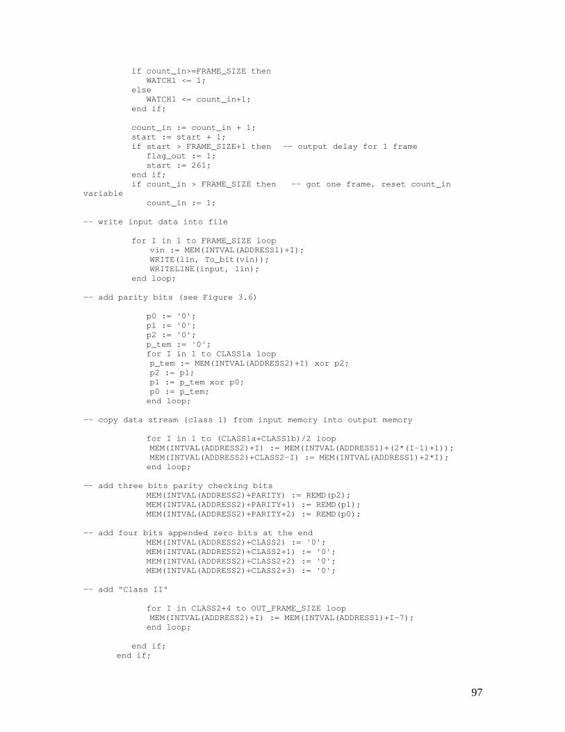
97
if count_in>=FRAME_SIZE thenWATCH1 <= 1;
elseWATCH1 <= count_in+1;
end if;
count_in := count_in + 1;start := start + 1;if start > FRAME_SIZE+1 then -- output delay for 1 frame
flag_out := 1;start := 261;
end if;if count_in > FRAME_SIZE then -- got one frame, reset count_in
variablecount_in := 1;
-- write input data into file
for I in 1 to FRAME_SIZE loopvin := MEM(INTVAL(ADDRESS1)+I);WRITE(lin, To_bit(vin));WRITELINE(input, lin);
end loop;
-- add parity bits (see Figure 3.6)
p0 := '0';p1 := '0';p2 := '0';p_tem := '0';for I in 1 to CLASS1a loopp_tem := MEM(INTVAL(ADDRESS2)+I) xor p2;p2 := p1;p1 := p_tem xor p0;p0 := p_tem;end loop;
-- copy data stream (class 1) from input memory into output memory
for I in 1 to (CLASS1a+CLASS1b)/2 loopMEM(INTVAL(ADDRESS2)+I) := MEM(INTVAL(ADDRESS1)+(2*(I-1)+1));MEM(INTVAL(ADDRESS2)+CLASS2-I) := MEM(INTVAL(ADDRESS1)+2*I);end loop;
-- add three bits parity checking bitsMEM(INTVAL(ADDRESS2)+PARITY) := REMD(p2);MEM(INTVAL(ADDRESS2)+PARITY+1) := REMD(p1);MEM(INTVAL(ADDRESS2)+PARITY+2) := REMD(p0);
-- add four bits appended zero bits at the endMEM(INTVAL(ADDRESS2)+CLASS2) := '0';MEM(INTVAL(ADDRESS2)+CLASS2+1) := '0';MEM(INTVAL(ADDRESS2)+CLASS2+2) := '0';MEM(INTVAL(ADDRESS2)+CLASS2+3) := '0';
-- add "Class II"
for I in CLASS2+4 to OUT_FRAME_SIZE loopMEM(INTVAL(ADDRESS2)+I) := MEM(INTVAL(ADDRESS1)+I-7);end loop;
end if;end if;
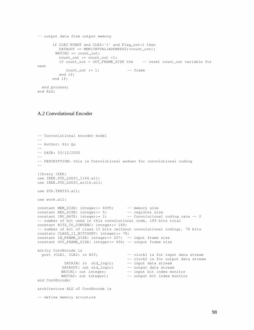
98
-- output data from output memory
if CLK2'EVENT and CLK2='1' and Flag_out=1 thenDATAOUT <= MEM(INTVAL(ADDRESS2)+count_out);
WATCH2 <= count_out;count_out := count_out +1;if count_out > OUT_FRAME_SIZE the -- reset count_out variable for
nextcount_out := 1; -- frame
end if;end if;
end process;end ALG;
A.2 Convolutional Encoder
-- Convonlutional encoder model---- Author: Xin Qu---- DATE: 03/12/2000---- DESCRIPTION: this is Convolutional endoer for convolutional coding--
library IEEE;use IEEE.STD_LOGIC_1164.all;use IEEE.STD_LOGIC_arith.all;
use STD.TEXTIO.all;
use work.all;
constant MEM_SIZE: integer:= 4095; -- memory sizeconstant REG_SIZE: integer:= 5; -- register sizeconstant INV_RATE: integer:= 2; -- Convolutional coding rate -- 2-- number of bit used in this convolutional code, 189 bits totalconstant BITS_TO_CONVENC: integer:= 189;-- number of bit of class II bits (without convolutional coding), 78 bitsconstatn CLASS_II_BITCOUNT: integer:= 78;constant IN_FRAME_SIZE: integer:= 267; -- input frame sizeconstant OUT_FRAME_SIZE: integer:= 456; -- output frame size
entity ConvEncode isport (CLK1, CLK2: in BIT; -- clock1 is for input data stream
-- clock2 is for output data streamDATAIN: in std_logic; -- input data streamDATAOUT: out std_logic; -- output data streamWATCH1: out integer; -- input bit index monitorWATCH2: out integer); -- output bit index monitor
end ConvEncode;
architecture ALG of ConvEncode is
-- define memory structure
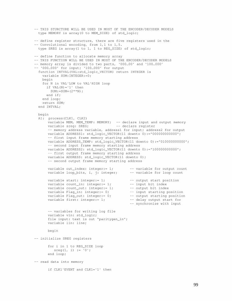
99
-- THIS STURCTURE WILL BE USED IN MOST OF THE ENCODER/DECODER MODELStype MEMORY is array(0 to MEM_SIZE) of std_logic;
-- define register structure, there are five registers used in the-- Convolutional encoding, from 1,1 to 1,5.
type SREG is array(1 to 1, 1 to REG_SIZE) of std_logic;
-- define function to allocate memory array-- THIS FUNCTION WILL BE USED IN MOST OF THE ENCODER/DECODER MODELS-- memory array is divided to two parts, ‘000…00’ and ‘100…000’-- ‘000…000’ for input; ‘100…000’ for output
function INTVAL(VAL:std_logic_VECTOR) return INTEGER isvariable SUM:INTEGER:=0;beginfor N in VAL'LOW to VAL'HIGH loop
if VAL(N)='1' thenSUM:=SUM+(2**N);
end if;end loop;return SUM;
end INTVAL;
beginA1: process(CLK1, CLK2)
variable MEM, MEM_TEMP: MEMORY; -- declare input and output memoryvariable sreg: SREG; -- declare register-- memory address variable, address1 for input; address2 for outputvariable ADDRESS1: std_logic_VECTOR(11 downto 0):="000000000000";-- first input frame memory starting addressvariable ADDRESS_TEMP: std_logic_VECTOR(11 downto 0):="010000000000";-- second input frame memory starting addressvariable ADDRESS2: std_logic_VECTOR(11 downto 0):="100000000000";-- first output frame memory starting addressvariable ADDRESS: std_logic_VECTOR(11 downto 0);-- second output frame memory starting address
variable out_index: integer:= 1; -- variable for output countvariable loop_bits, i, j: integer; -- variable for loop count
variable start: integer:= 1; -- output start positionvariable count_in: integer:= 1; -- input bit indexvariable count_out: integer:= 1; -- output bit indexvariable Flag_in: integer:= 0; -- input starting positionvariable Flag_out: integer:= 0; -- output starting positionvariable first: integer:= 1; -- delay output start for
-- synchronize with input
-- variables for writing log filevariable vin: std_logic;file input: text is out "paritygen_in";variable lin: line;
begin
-- initialize SREG registers
for i in 1 to REG_SIZE loopsreg(1, i) := '0';
end loop;
-- read data into memory
if CLK1'EVENT and CLK1='1' then
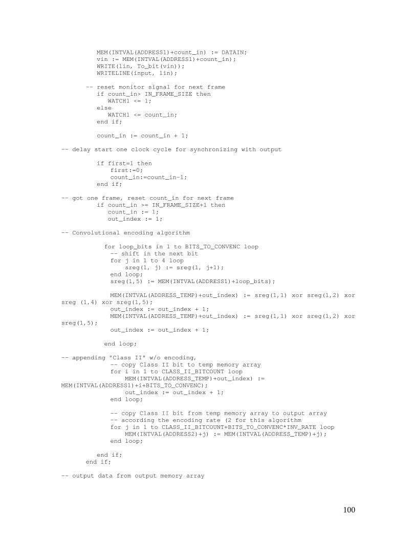
100
MEM(INTVAL(ADDRESS1)+count_in) := DATAIN;vin := MEM(INTVAL(ADDRESS1)+count_in);WRITE(lin, To_bit(vin));WRITELINE(input, lin);
-- reset monitor signal for next frameif count_in> IN_FRAME_SIZE then
WATCH1 <= 1;else
WATCH1 <= count_in;end if;
count_in := count_in + 1;
-- delay start one clock cycle for synchronizing with output
if first=1 thenfirst:=0;count_in:=count_in-1;
end if;
-- got one frame, reset count_in for next frameif count_in >= IN_FRAME_SIZE+1 then
count_in := 1;out_index := 1;
-- Convolutional encoding algorithm
for loop_bits in 1 to BITS_TO_CONVENC loop-- shift in the next bitfor j in 1 to 4 loop
sreg(1, j) := sreg(1, j+1);end loop;sreg(1,5) := MEM(INTVAL(ADDRESS1)+loop_bits);
MEM(INTVAL(ADDRESS_TEMP)+out_index) := sreg(1,1) xor sreg(1,2) xorsreg (1,4) xor sreg(1,5);
out_index := out_index + 1;MEM(INTVAL(ADDRESS_TEMP)+out_index) := sreg(1,1) xor sreg(1,2) xor
sreg(1,5);out_index := out_index + 1;
end loop;
-- appending "Class II" w/o encoding,-- copy Class II bit to temp memory arrayfor i in 1 to CLASS_II_BITCOUNT loop
MEM(INTVAL(ADDRESS_TEMP)+out_index) :=MEM(INTVAL(ADDRESS1)+i+BITS_TO_CONVENC);
out_index := out_index + 1;end loop;
-- copy Class II bit from temp memory array to output array-- according the encoding rate (2 for this algorithmfor j in 1 to CLASS_II_BITCOUNT+BITS_TO_CONVENC*INV_RATE loop
MEM(INTVAL(ADDRESS2)+j) := MEM(INTVAL(ADDRESS_TEMP)+j);end loop;
end if;end if;
-- output data from output memory array
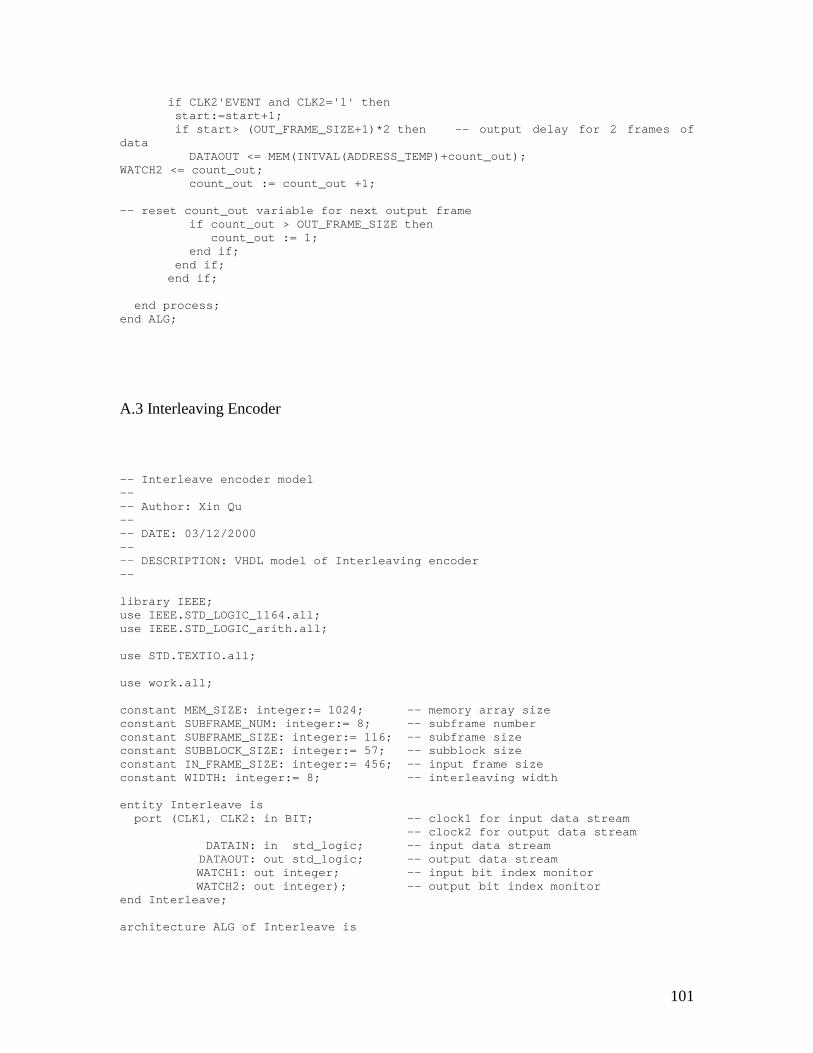
101
if CLK2'EVENT and CLK2='1' thenstart:=start+1;if start> (OUT_FRAME_SIZE+1)*2 then -- output delay for 2 frames of
dataDATAOUT <= MEM(INTVAL(ADDRESS_TEMP)+count_out);
WATCH2 <= count_out;count_out := count_out +1;
-- reset count_out variable for next output frameif count_out > OUT_FRAME_SIZE then
count_out := 1;end if;
end if;end if;
end process;end ALG;
A.3 Interleaving Encoder
-- Interleave encoder model---- Author: Xin Qu---- DATE: 03/12/2000---- DESCRIPTION: VHDL model of Interleaving encoder--
library IEEE;use IEEE.STD_LOGIC_1164.all;use IEEE.STD_LOGIC_arith.all;
use STD.TEXTIO.all;
use work.all;
constant MEM_SIZE: integer:= 1024; -- memory array sizeconstant SUBFRAME_NUM: integer:= 8; -- subframe numberconstant SUBFRAME_SIZE: integer:= 116; -- subframe sizeconstant SUBBLOCK_SIZE: integer:= 57; -- subblock sizeconstant IN_FRAME_SIZE: integer:= 456; -- input frame sizeconstant WIDTH: integer:= 8; -- interleaving width
entity Interleave isport (CLK1, CLK2: in BIT; -- clock1 for input data stream
-- clock2 for output data streamDATAIN: in std_logic; -- input data streamDATAOUT: out std_logic; -- output data streamWATCH1: out integer; -- input bit index monitorWATCH2: out integer); -- output bit index monitor
end Interleave;
architecture ALG of Interleave is
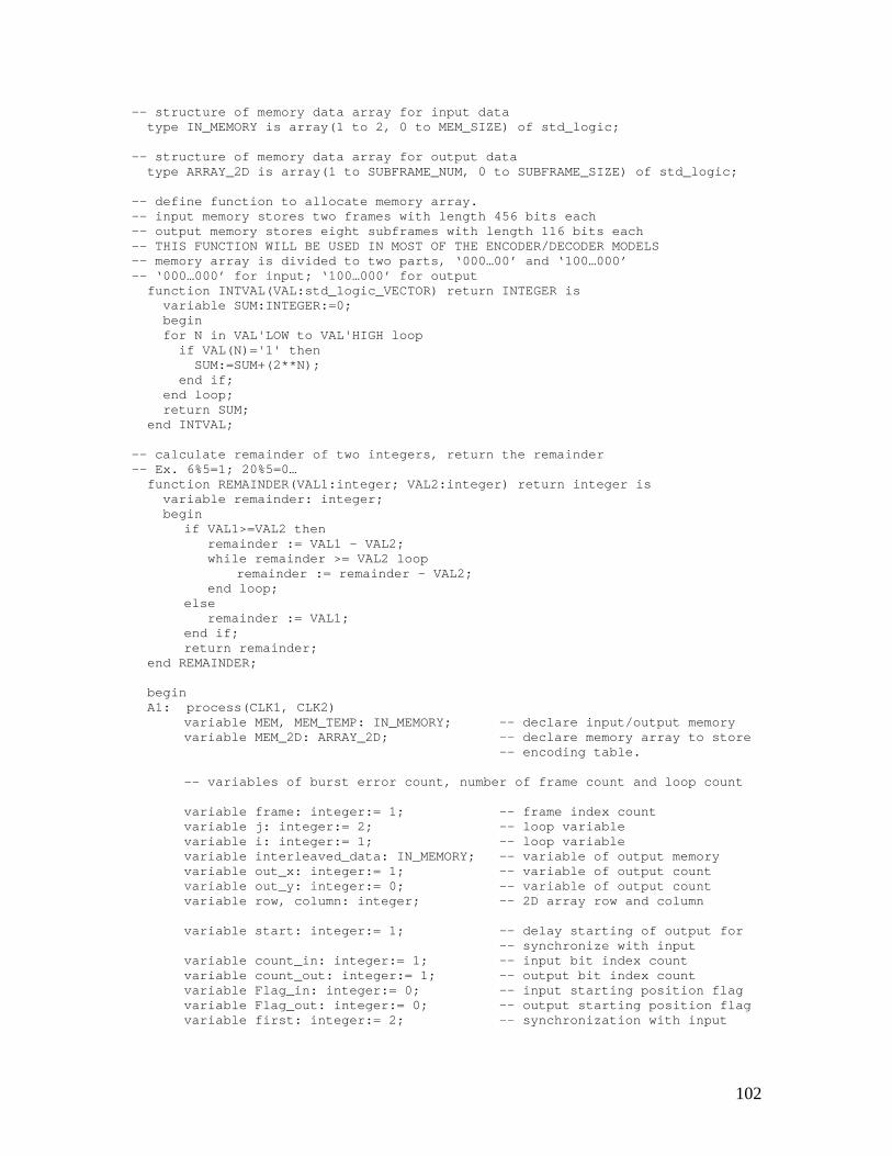
102
-- structure of memory data array for input datatype IN_MEMORY is array(1 to 2, 0 to MEM_SIZE) of std_logic;
-- structure of memory data array for output datatype ARRAY_2D is array(1 to SUBFRAME_NUM, 0 to SUBFRAME_SIZE) of std_logic;
-- define function to allocate memory array.-- input memory stores two frames with length 456 bits each-- output memory stores eight subframes with length 116 bits each-- THIS FUNCTION WILL BE USED IN MOST OF THE ENCODER/DECODER MODELS-- memory array is divided to two parts, ‘000…00’ and ‘100…000’-- ‘000…000’ for input; ‘100…000’ for output
function INTVAL(VAL:std_logic_VECTOR) return INTEGER isvariable SUM:INTEGER:=0;beginfor N in VAL'LOW to VAL'HIGH loop
if VAL(N)='1' thenSUM:=SUM+(2**N);
end if;end loop;return SUM;
end INTVAL;
-- calculate remainder of two integers, return the remainder-- Ex. 6%5=1; 20%5=0…
function REMAINDER(VAL1:integer; VAL2:integer) return integer isvariable remainder: integer;begin
if VAL1>=VAL2 thenremainder := VAL1 - VAL2;while remainder >= VAL2 loop
remainder := remainder - VAL2;end loop;
elseremainder := VAL1;
end if;return remainder;
end REMAINDER;
beginA1: process(CLK1, CLK2)
variable MEM, MEM_TEMP: IN_MEMORY; -- declare input/output memoryvariable MEM_2D: ARRAY_2D; -- declare memory array to store
-- encoding table.
-- variables of burst error count, number of frame count and loop count
variable frame: integer:= 1; -- frame index countvariable j: integer:= 2; -- loop variablevariable i: integer:= 1; -- loop variablevariable interleaved_data: IN_MEMORY; -- variable of output memoryvariable out_x: integer:= 1; -- variable of output countvariable out_y: integer:= 0; -- variable of output countvariable row, column: integer; -- 2D array row and column
variable start: integer:= 1; -- delay starting of output for-- synchronize with input
variable count_in: integer:= 1; -- input bit index countvariable count_out: integer:= 1; -- output bit index countvariable Flag_in: integer:= 0; -- input starting position flagvariable Flag_out: integer:= 0; -- output starting position flagvariable first: integer:= 2; -- synchronization with input
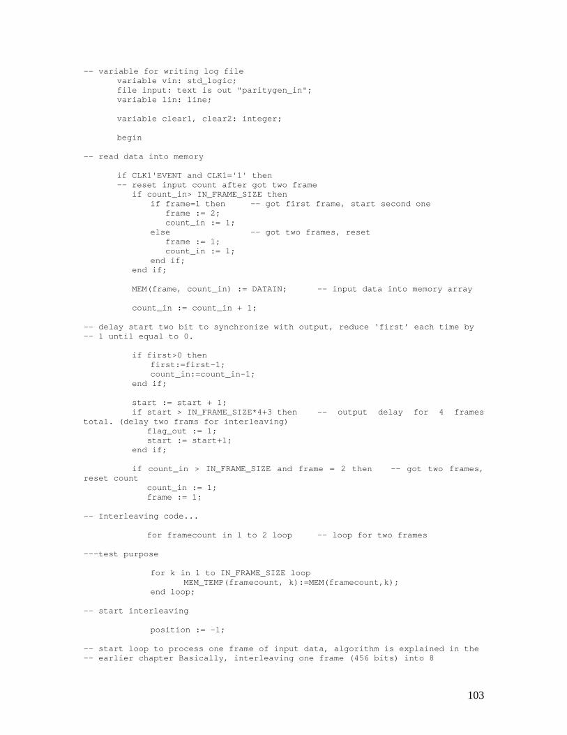
103
-- variable for writing log filevariable vin: std_logic;file input: text is out "paritygen_in";variable lin: line;
variable clear1, clear2: integer;
begin
-- read data into memory
if CLK1'EVENT and CLK1='1' then-- reset input count after got two frame
if count_in> IN_FRAME_SIZE thenif frame=1 then -- got first frame, start second one
frame := 2;count_in := 1;
else -- got two frames, resetframe := 1;count_in := 1;
end if;end if;
MEM(frame, count_in) := DATAIN; -- input data into memory array
count_in := count_in + 1;
-- delay start two bit to synchronize with output, reduce ‘first’ each time by-- 1 until equal to 0.
if first>0 thenfirst:=first-1;count_in:=count_in-1;
end if;
start := start + 1;if start > IN_FRAME_SIZE*4+3 then -- output delay for 4 frames
total. (delay two frams for interleaving)flag_out := 1;start := start+1;
end if;
if count_in > IN_FRAME_SIZE and frame = 2 then -- got two frames,reset count
count_in := 1;frame := 1;
-- Interleaving code...
for framecount in 1 to 2 loop -- loop for two frames
---test purpose
for k in 1 to IN_FRAME_SIZE loopMEM_TEMP(framecount, k):=MEM(framecount,k);
end loop;
-- start interleaving
position := -1;
-- start loop to process one frame of input data, algorithm is explained in the-- earlier chapter Basically, interleaving one frame (456 bits) into 8
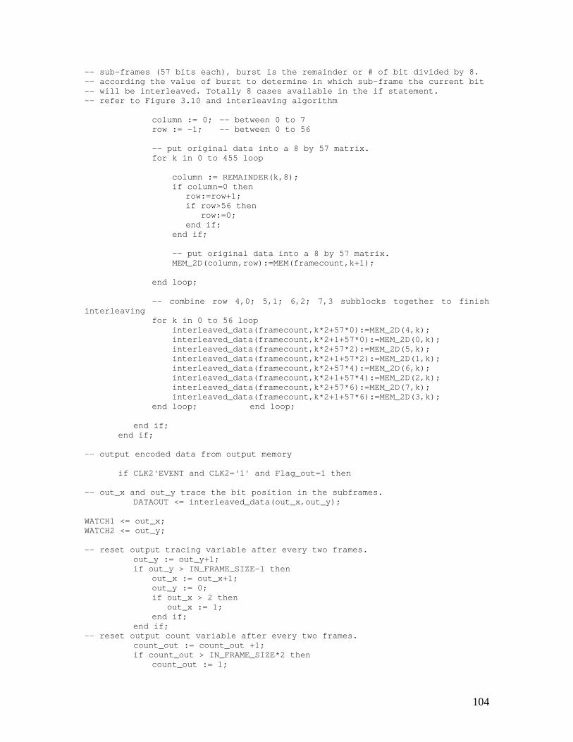
104
-- sub-frames (57 bits each), burst is the remainder or # of bit divided by 8.-- according the value of burst to determine in which sub-frame the current bit-- will be interleaved. Totally 8 cases available in the if statement.-- refer to Figure 3.10 and interleaving algorithm
column := 0; -- between 0 to 7row := -1; -- between 0 to 56
-- put original data into a 8 by 57 matrix.for k in 0 to 455 loop
column := REMAINDER(k,8);if column=0 then
row:=row+1;if row>56 then
row:=0;end if;
end if;
-- put original data into a 8 by 57 matrix.MEM_2D(column,row):=MEM(framecount,k+1);
end loop;
-- combine row 4,0; 5,1; 6,2; 7,3 subblocks together to finishinterleaving
for k in 0 to 56 loopinterleaved_data(framecount,k*2+57*0):=MEM_2D(4,k);interleaved_data(framecount,k*2+1+57*0):=MEM_2D(0,k);interleaved_data(framecount,k*2+57*2):=MEM_2D(5,k);interleaved_data(framecount,k*2+1+57*2):=MEM_2D(1,k);interleaved_data(framecount,k*2+57*4):=MEM_2D(6,k);interleaved_data(framecount,k*2+1+57*4):=MEM_2D(2,k);interleaved_data(framecount,k*2+57*6):=MEM_2D(7,k);interleaved_data(framecount,k*2+1+57*6):=MEM_2D(3,k);
end loop; end loop;
end if;end if;
-- output encoded data from output memory
if CLK2'EVENT and CLK2='1' and Flag_out=1 then
-- out_x and out_y trace the bit position in the subframes.DATAOUT <= interleaved_data(out_x,out_y);
WATCH1 <= out_x;WATCH2 <= out_y;
-- reset output tracing variable after every two frames.out_y := out_y+1;if out_y > IN_FRAME_SIZE-1 then
out_x := out_x+1;out_y := 0;if out_x > 2 then
out_x := 1;end if;
end if;-- reset output count variable after every two frames.
count_out := count_out +1;if count_out > IN_FRAME_SIZE*2 then
count_out := 1;
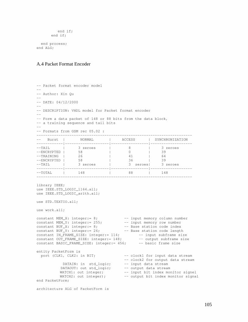
105
end if;end if;
end process;end ALG;
A.4 Packet Format Encoder
-- Packet format encoder model---- Author: Xin Qu---- DATE: 04/12/2000---- DESCRIPTION: VHDL model for Packet format encoder---- Form a data packet of 148 or 88 bits from the data block,-- a training sequence and tail bits---- Formats from GSM rec 05.02 :------------------------------------------------------------------------- Burst | NORMAL | ACCESS | SYNCHRONIZATION------------|--------------------|-----------------|---------------------TAIL | 3 zeroes | 8 | 3 zeroes--ENCRYPTED | 58 | 0 | 39--TRAINING | 26 | 41 | 64--ENCRYPTED | 58 | 36 | 39--TAIL | 3 zeroes | 3 zeroes| 3 zeroes------------|--------------------|-----------------|---------------------TOTAL | 148 | 88 | 148-----------------------------------------------------------------------
library IEEE;use IEEE.STD_LOGIC_1164.all;use IEEE.STD_LOGIC_arith.all;
use STD.TEXTIO.all;
use work.all;
constant MEM_X: integer:= 8; -- input memory column numberconstant MEM_Y: integer:= 255; -- input memory row numberconstant BUF_X: integer:= 8; -- Base station code indexconstant BUF_Y: integer:= 26; -- Base station code lengthconstant IN_FRAME_SIZE: integer:= 114; -- input subframe sizeconstant OUT_FRAME_SIZE: integer:= 148; -- output subframe sizeconstant BASIC_FRAME_SIZE: integer:= 456; -- basic frame size
entity PacketForm isport (CLK1, CLK2: in BIT; -- clock1 for input data stream
-- clock2 for output data streamDATAIN: in std_logic; -- input data streamDATAOUT: out std_logic; -- output data streamWATCH1: out integer; -- input bit index monitor signelWATCH2: out integer); -- output bit index monitor signal
end PacketForm;
architecture ALG of PacketForm is
106
-- define memory structuretype MEMORY is array(1 to MEM_X, 0 to MEM_Y) of std_logic;
-- define buffer structure for training sequencetype BUF is array(1 to BUF_X, 1 to BUF_Y) of std_logic;
-- Returns BASE STATION CODE-- there are totally eight base station codes list here, each one contains-- 26 bits.
function GetBSIC(index:integer) return BUF isvariable tseq:
BUF:=(('0','0','1','0','0','1','0','1','1','1','0','0','0','0','1','0','0','0','1','0','0','1','0','1','1','1'),
('0','0','1','0','1','1','0','1','1','1','0','1','1','1','1','0','0','0','1','0','1','1','0','1','1','1'),
('0','1','0','0','0','0','1','1','1','0','1','1','1','0','1','0','0','1','0','0','0','0','1','1','1','0'),
('0','1','0','0','0','1','1','1','1','0','1','1','0','1','0','0','0','1','0','0','0','1','1','1','1','0'),
('0','0','0','1','1','0','1','0','1','1','1','0','0','1','0','0','0','0','0','1','1','0','1','0','1','1'),
('0','1','0','0','1','1','1','0','1','0','1','1','0','0','0','0','0','1','0','0','1','1','1','0','1','0'),
('1','0','1','0','0','1','1','1','1','1','0','1','1','0','0','0','1','0','1','0','0','1','1','1','1','1'),
('1','1','1','0','1','1','1','1','0','0','0','1','0','0','1','0','1','1','1','0','1','1','1','1','0','0'));
variable output: BUF; -- output buffervariable i: integer; -- loop count variablebegin
-- copy training sequence into output bufferfor i in 1 to BUF_Y loop
output(1, i) := tseq(index, i);end loop;return output;
end GetBSIC;
beginA1: process(CLK1, CLK2)
variable in_mem, out_mem, MEM_TEMP: MEMORY; -- declare input/outputmemory
variable out_x: integer:= 1; -- output trace variablevariable out_y: integer:= 1; -- output trace variablevariable framecount: integer; -- frame count variablevariable i: integer; -- loop count variable
variable start: integer:= 1; -- start output countvariable frame: integer:= 1; -- frame trace variablevariable count_in: integer:= 1; -- input count variable
107
variable count_out: integer:= 1; -- output count variablevariable Flag_in: integer:= 0; -- input starting position flagvariable Flag_out: integer:= 0; -- output starting position flagvariable first: integer:= 3; -- synchronization with input
-- variable for writing log filevariable vin: std_logic;file input: text is out "paritygen_in";variable lin: line;
variable TR_INDEX: integer:= 0; -- training sequence indexvariable x: BUF; -- buffer value
begin
-- read data into memory
if CLK1'EVENT and CLK1='1' then
if count_in> IN_FRAME_SIZE then -- reset count_in for eachsubframe
frame := frame + 1;count_in := 1;if frame > 4 then
frame := 1; -- reset frame count after each frameend if;
end if;
in_mem(frame, count_in) := DATAIN; -- read data into memory array
count_in := count_in + 1;
-- delay start three bit to synchronize with output
if first>0 thenfirst:=first-1;count_in:=count_in-1;
end if;
start := start + 1;if start > BASIC_FRAME_SIZE*4+3 then
flag_out := 1;start := start+1; -- output delay for 5 frames
end if;
if count_in > IN_FRAME_SIZE and frame = 4 then -- got four sub-frames
count_in := 1;frame := 1;
-- Packet speech data...-- TR_INDEX is the index number of burst structure (there is only one kind-- of burst structure is implemented in the model – normal burst; could be-- configured later for more kinds of bursts-- re-formatting the input sub-frame
for burstloop in 1 to 4 loop
if TR_INDEX=50 thenfor j in 1 to 3 loop
out_mem(burstloop, j) := '0';out_mem(burstloop, 149-j) := '0';
end loop;
108
for j in 1 to 39 loopout_mem(burstloop, j+3) := in_mem(burstloop, j);out_mem(burstloop, j+106) := in_mem(burstloop, j+39);
end loop;
elsif TR_INDEX=51 thenfor j in 1 to 3 loop
out_mem(burstloop, 89-j) := '0';end loop;
for j in 1 to 36 loopout_mem(burstloop, j+49) := in_mem(burstloop, j);
end loop;else
-- add tail bitsfor j in 1 to 3 loop
out_mem(burstloop, j) := '0';out_mem(burstloop, 149-j) := '0';
end loop;-- copy coded data
for j in 1 to 57 loopout_mem(burstloop, j+3) := in_mem(burstloop, j);out_mem(burstloop, j+88) := in_mem(burstloop, j+57);
end loop;-- add stealing flag
out_mem(burstloop, 61):='0';out_mem(burstloop, 88):='0';
-- add training sequencefor j in 1 to BUF_Y loop
x := GetBSIC(TR_INDEX + 1);out_mem(burstloop, j+61) := x(1, j);
end loop;end if;
end loop;
end if;end if;
-- read data out of memory
if CLK2'EVENT and CLK2='1' and Flag_out=1 thenif out_y>OUT_FRAME_SIZE then -- reset output tracing
variableout_x := out_x+1;out_y := 1;if out_x>4 then
out_x := 1;end if;
end if;
DATAOUT <= out_mem(out_x,out_y); -- output data from output memory
WATCH1 <= out_x;WATCH2 <= out_y;
out_y := out_y+1;count_out := count_out +1;if count_out > OUT_FRAME_SIZE*4*3 then -- reset output count variable
count_out := 1;end if;
end if;
end process;end ALG;
109
A.5 Differential Encoder
--Differential encoder model---- Author: Xin Qu---- DATE: 05/15/2000---- DESCRIPTION: VHDL model of differential decoder--
library IEEE;use IEEE.STD_LOGIC_1164.all;use IEEE.STD_LOGIC_arith.all;
use STD.TEXTIO.all;
use work.all;
constant MEMORY_X: integer:= 12; -- memory metric number or columnconstant MEMORY_Y: integer:= 256; -- memory metric number or rowconstant BIT_IN_SUBFRAME: integer := 148 -- number of bit in a frameconstant BIT_IN_OUT_FRAME: integer:= 1776 –number of bit in output frame
entity DiffEncode isport (CLK1: in BIT; -- clock signals
DATAIN: in std_logic; -- input data streamDATAOUT: out std_logic; -- output data streamWATCH1: out integer; -- output bit count monitor signalWATCH2: out integer); -- output bit count monitor signal
-- WATCH signals are for debugging.end DiffEncode;
architecture ALG of DiffEncode is
-- define structure of memory arraytype MEMORY is array(1 to MEMORY_X, 0 to MEMORY_Y) of std_logic;
beginA1: process(CLK1)
variable in_mem, out_mem, MEM_TEMP: MEMORY; -- memory variablevariable out_x: integer:= 1;-- output trace variable for the output frame indexvariable out_y: integer:= 1;-- output trace variable for the output bit index in a framevariable framecount: integer; -- frame count for
decoding loop, each time decoding four frames and each frame has 148 bits.variable i: integer; -- loop count variable
variable start: integer:= 1; -- delay starting untilthe input comes.
variable frame: integer:= 1; -- frame number count
110
variable count_in: integer:= 1; -- count input bitsvariable count_out: integer:= 1; -- count_output bitsvariable Flag_in: integer:= 0; -- flag of input startvariable Flag_out: integer:= 0; -- flag of output startvariable first: integer:= 4; -- output delay variable
to synchronize with input
-- variable of writing log filevariable vin: std_logic;file input: text is out "paritygen_in";variable lin: line;
begin
-- read data into memory
if CLK1'EVENT and CLK1='1' then
-- reset input counting variable for each sub-frame of dataif count_in> BIT_IN_SUBFRAME then
frame := frame + 1;count_in := 1;
-- each time read in four sub-frmae of data to decode then reset frame countingvariable
if frame > 4 thenframe := 1;
end if;end if;
in_mem(frame, count_in) := DATAIN; -- read input data into memory,each row contains one frame of data (148 bits).
count_in := count_in + 1;
-- delay start four clock cycle to synchronize with output
if first>0 thenfirst:=first-1;count_in:=count_in-1;
end if;
start := start + 1;if start > BIT_IN_SUBFRAME*4*6+first then
-- delay output for six frames because each encoder/decoder has delay oneor two frames of data, there are four encoders in front of this. One framecontains 4 subframe which has 148 bits so the totally delay become 148*4*6 andin addition, there are 4 bits delay for sychronize reason.
flag_out := 1;start := start+1;
end if;
-- reset input count variable and frame count variableif count_in > BIT_IN_SUBFRAME and frame = 4 then
count_in := 1;frame := 1;
-- Differentially encode...
-- start differential encoding-- The differential encoding algorithm was explained in the early chapter-- the code below will copy the first input bit to the output, then
111
-- from the second input bit until the end of the frame, the encoder exclusive-- or the current input bit with the last input bit, then exclusive or ‘1’ to-- calculate the output
for framecount in 1 to 4 loopfor i in 1 to BIT_IN_SUBFRAME loop
out_mem(framecount,1):=in_mem(framecount,1);for i in 2 to BIT_IN_SUBFRAME loop
out_mem(framecount,i):=in_mem(framecount,i-1) xorin_mem(framecount,I) xor ‘1’;
end loop;end loop;
end loop;end if;
end if;
-- read data out of memory
if CLK1'EVENT and CLK1='1' and Flag_out=1 then-- reset output count variable
if out_y> BIT_IN_SUBFRAME thenout_x := out_x+1;out_y := 1;if out_x>4 then
out_x := 1;end if;
end if;
-- output data from output memory arrayDATAOUT <= out_mem(out_x, out_y); -- out_x is the number of column
-- out_x is the number of row
WATCH1 <= out_x;WATCH2 <= out_y;
out_y := out_y+1;count_out := count_out +1;if count_out > BIT_IN_OUT_FRAME then -- reset output count variable
count_out := 1;end if;
end if;
end process;end ALG;
112
Appendix B: VHDL code for GSM decoder models
B.1 Differential Decoder
--Differential decoder model---- Author: Xin Qu---- DATE: 05/15/2000---- DESCRIPTION: VHDL differential decoder model---- NOTE: the variables and functions used in the differential decoder are the-- same as the variables and functions used in the differential encoder model.-- Please look up the encoder model for reference. The decoding algorithm will-- be explained later
library IEEE;use IEEE.STD_LOGIC_1164.all;use IEEE.STD_LOGIC_arith.all;
use STD.TEXTIO.all;
use work.all;
constant MEMORY_X: integer:= 12; -- memory metric number or columnconstant MEMORY_Y: integer:= 256; -- memory metric number or rowconstant BIT_IN_SUBFRAME: integer := 148 -- number of bit in a frameconstant BIT_IN_OUT_FRAME: integer:= 1776 –-number of bit in output frame
entity DiffDecode isport (CLK1: in BIT;
DATAIN: in std_logic;DATAOUT: out std_logic;WATCH1: out integer; -- monitor signalWATCH2: out integer); -- monitor signal
end DiffDecode;
113
architecture ALG of DiffDecode is
type MEMORY is array(1 to MEMORY_X, 0 to MEMORY_Y) of std_logic;
beginA1: process(CLK1)
variable out_mem, MEM_TEMP: MEMORY;variable out_x: integer:= 1;variable out_y: integer:= 1;variable framecount: integer;variable i: integer;variable lasttime: std_logic;
variable start: integer:= 1;variable frame: integer:= 1;variable count_in: integer:= 1;variable count_out: integer:= 1;variable Flag_in: integer:= 0;variable Flag_out: integer:= 0;variable first: integer:= 5;
variable vin: std_logic;file input: text is out "paritygen_in";variable lin: line;
begin
-- read data into memory
if CLK1'EVENT and CLK1='1' then
if count_in> BIT_IN_SUBFRAME thenframe := frame + 1;count_in := 1;if frame > 4 then
frame := 1;end if;
end if;
in_mem(frame, count_in) := DATAIN;
count_in := count_in + 1;
-- delay start five bit-- the delay start variable may have different value came from the sequence oftests I did to synchronize the output with input, don’t know why they might bedifferent.
if first>0 thenfirst:=first-1;count_in:=count_in-1;
end if;
start := start + 1;if start > BIT_IN_SUBFRAME*4*7 +1 then -- output delay for 7
framesflag_out := 1;start := start+1;
end if;
if count_in > BIT_IN_SUBFRAME and frame = 4 then -- got two framescount_in := 1;
114
frame := 1;
-- Differentially decode...
for framecount in 1 to 4 loop
-- start decoding...-- The differential decoding algorithm was explained in the early chapter-- the code below will copy the first input bit to the output, then-- from the second input bit until the end of the frame, the encoder exclusive-- or the current input bit with the last output bit, then exclusive or ‘1’ to-- calculate the output
out_mem(framecount,1):=in_mem(framecount,1);for i in 2 to BIT_IN_SUBFRAME loop
out_mem(framecount,i):=in_mem(framecount,i) xorout_mem(framecount,i-1) xor ‘1’;
end loop;end loop;
end if;end if;
-- read data out of memory
if CLK1'EVENT and CLK1='1' and Flag_out=1 thenif out_y> BIT_IN_SUBFRAME then
out_x := out_x+1;out_y := 1;if out_x>4 then
out_x := 1;end if;
end if;
DATAOUT <= out_mem(out_x, out_y);
WATCH1 <= out_x;WATCH2 <= out_y;
out_y := out_y+1;count_out := count_out +1;if count_out > BIT_IN_OUT_FRAME then
count_out := 1;end if;
end if;
end process;end ALG;
B.2 Packet Format Decoder
-- Packet format decoder model---- Author: Xin Qu---- DATE: 05/15/2000--
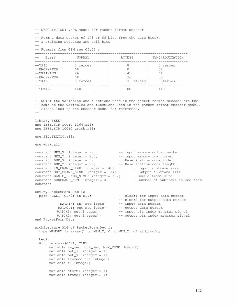
115
-- DESCRIPTION: VHDL model for Packet format decoder---- Form a data packet of 148 or 88 bits from the data block,-- a training sequence and tail bits---- Formats from GSM rec 05.02 :--------------------------------------------------------------------------- Burst | NORMAL | ACCESS | SYNCHRONIZATION------------|----------------------|-----------------|---------------------TAIL | 3 zeroes | 8 | 3 zeroes--ENCRYPTED | 58 | 0 | 39--TRAINING | 26 | 41 | 64--ENCRYPTED | 58 | 36 | 39--TAIL | 3 zeroes | 3 zeroes| 3 zeroes------------|----------------------|-----------------|---------------------TOTAL | 148 | 88 | 148----------------------------------------------------------------------------- NOTE: the variables and functions used in the packet format decoder are the-- same as the variables and functions used in the packet format encoder model.-- Please look up the encoder model for reference.--
library IEEE;use IEEE.STD_LOGIC_1164.all;use IEEE.STD_LOGIC_arith.all;
use STD.TEXTIO.all;
use work.all;
constant MEM_X: integer:= 8; -- input memory column numberconstant MEM_Y: integer:= 255; -- input memory row numberconstant BUF_X: integer:= 8; -- Base station code indexconstant BUF_Y: integer:= 26; -- Base station code lengthconstant IN_FRAME_SIZE: integer:= 148; -- input subframe sizeconstant OUT_FRAME_SIZE: integer:= 114; -- output subframe sizeconstant BASIC_FRAME_SIZE: integer:= 592; -- basic frame sizeconstant SUBFRAME_NUM: integer:= 4; -- number of subframe in one framconstant
entity PacketForm_Dec isport (CLK1, CLK2: in BIT; -- clock1 for input data stream
-- clock2 for output data streamDATAIN: in std_logic; -- input data streamDATAOUT: out std_logic; -- output data streamWATCH1: out integer; -- input bit index monitor signalWATCH2: out integer); -- output bit index monitor signal
end PacketForm_Dec;
architecture ALG of PacketForm_Dec istype MEMORY is array(1 to MEM_X, 0 to MEM_Y) of std_logic;
beginA1: process(CLK1, CLK2)
variable in_mem, out_mem, MEM_TEMP: MEMORY;variable out_x: integer:= 1;variable out_y: integer:= 1;variable framecount: integer;variable i: integer;
variable start: integer:= 1;variable frame: integer:= 1;
116
variable count_in: integer:= 0;variable count_out: integer:= 1;variable Flag_in: integer:= 0;variable Flag_out: integer:= 0;variable first: integer:= 4;
variable vin: std_logic;file input: text is out "paritygen_in";variable lin: line;
variable TR_INDEX: integer:= 0;
begin
-- read data into memory
if CLK1'EVENT and CLK1='1' then
if count_in> IN_FRAME_SIZE thenframe := frame + 1;count_in := 1;if frame > SUBFRAME_NUM then
frame := 1;end if;
end if;
in_mem(frame, count_in) := DATAIN;
count_in := count_in + 1;
-- delay start four clock cycle to synchronize with output
if first>0 thenfirst:=first-1;count_in:=count_in-1;
end if;
start := start + 1;if start > BASIC_FRAME_SIZE*8+5 then -- output delay for 8 fram
flag_out := 1;start := start+1;
end if;
if count_in > IN_FRAME_SIZE and frame = SUBFRAME_NUM then -- got twoframes
count_in := 1;frame := 1;
-- Restore packet speech data...
-- loop for each sub-frame, take out the training sequence and tail bits,-- guard bit… copy the speech information payload into the output memory array
for burstloop in 1 to SUBFRAME_NUM loop
for i in 1 to 57 loopout_mem(burstloop, i) := in_mem(burstloop, i+3);out_mem(burstloop, i+57) := in_mem(burstloop, i+88);
end loop;
end loop;
end if;
117
end if;
-- read data out of memory
if CLK2'EVENT and CLK2='1' and Flag_out=1 thenif out_y>114 then
out_x := out_x+1;out_y := 1;if out_x>4 then
out_x := 1;end if;
end if;
DATAOUT <= out_mem(out_x,out_y);
WATCH1 <= out_x;WATCH2 <= out_y;
out_y := out_y+1;count_out := count_out +1;if count_out > OUT_FRAME_SIZE*4 then
count_out := 1;end if;
end if;
end process;end ALG;
B.3 Interleaving Decoder
-- Interleaving decoder model---- Author: Xin Qu---- DATE: 05/15/2000---- DESCRIPTION: VHDL model for Interleaving decoder---- NOTE: the variables and functions used in the interleaving decoder are the-- same as the variables and functions used in the interleaving encoder model.-- Please look up the encoder model for reference.--
library IEEE;use IEEE.STD_LOGIC_1164.all;use IEEE.STD_LOGIC_arith.all;
use STD.TEXTIO.all;
use work.all;
constant RRAME_SIZE: integer:= 456; -- frame size
entity De_Interleave isport (CLK1, CLK2: in BIT;
DATAIN: in std_logic;
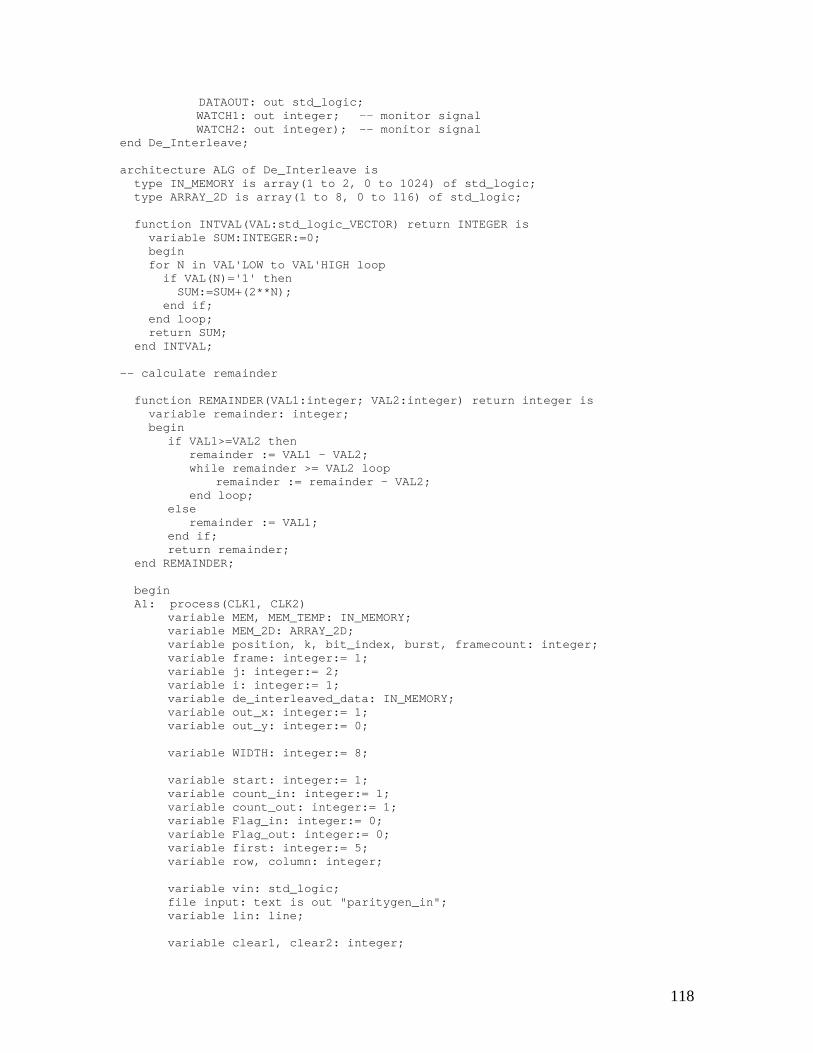
118
DATAOUT: out std_logic;WATCH1: out integer; -- monitor signalWATCH2: out integer); -- monitor signal
end De_Interleave;
architecture ALG of De_Interleave istype IN_MEMORY is array(1 to 2, 0 to 1024) of std_logic;type ARRAY_2D is array(1 to 8, 0 to 116) of std_logic;
function INTVAL(VAL:std_logic_VECTOR) return INTEGER isvariable SUM:INTEGER:=0;beginfor N in VAL'LOW to VAL'HIGH loop
if VAL(N)='1' thenSUM:=SUM+(2**N);
end if;end loop;return SUM;
end INTVAL;
-- calculate remainder
function REMAINDER(VAL1:integer; VAL2:integer) return integer isvariable remainder: integer;begin
if VAL1>=VAL2 thenremainder := VAL1 - VAL2;while remainder >= VAL2 loop
remainder := remainder - VAL2;end loop;
elseremainder := VAL1;
end if;return remainder;
end REMAINDER;
beginA1: process(CLK1, CLK2)
variable MEM, MEM_TEMP: IN_MEMORY;variable MEM_2D: ARRAY_2D;variable position, k, bit_index, burst, framecount: integer;variable frame: integer:= 1;variable j: integer:= 2;variable i: integer:= 1;variable de_interleaved_data: IN_MEMORY;variable out_x: integer:= 1;variable out_y: integer:= 0;
variable WIDTH: integer:= 8;
variable start: integer:= 1;variable count_in: integer:= 1;variable count_out: integer:= 1;variable Flag_in: integer:= 0;variable Flag_out: integer:= 0;variable first: integer:= 5;variable row, column: integer;
variable vin: std_logic;file input: text is out "paritygen_in";variable lin: line;
variable clear1, clear2: integer;
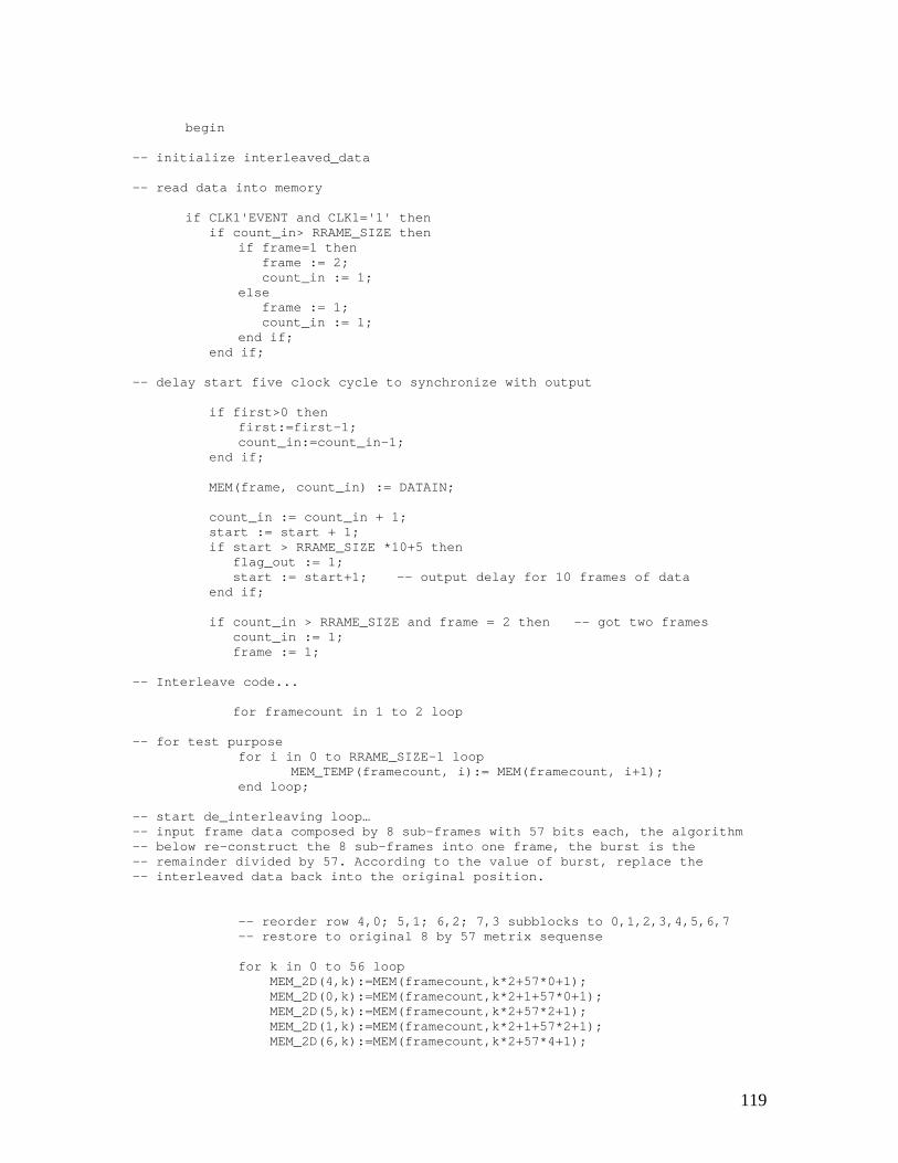
119
begin
-- initialize interleaved_data
-- read data into memory
if CLK1'EVENT and CLK1='1' thenif count_in> RRAME_SIZE then
if frame=1 thenframe := 2;count_in := 1;
elseframe := 1;count_in := 1;
end if;end if;
-- delay start five clock cycle to synchronize with output
if first>0 thenfirst:=first-1;count_in:=count_in-1;
end if;
MEM(frame, count_in) := DATAIN;
count_in := count_in + 1;start := start + 1;if start > RRAME_SIZE *10+5 then
flag_out := 1;start := start+1; -- output delay for 10 frames of data
end if;
if count_in > RRAME_SIZE and frame = 2 then -- got two framescount_in := 1;frame := 1;
-- Interleave code...
for framecount in 1 to 2 loop
-- for test purposefor i in 0 to RRAME_SIZE-1 loop
MEM_TEMP(framecount, i):= MEM(framecount, i+1);end loop;
-- start de_interleaving loop…-- input frame data composed by 8 sub-frames with 57 bits each, the algorithm-- below re-construct the 8 sub-frames into one frame, the burst is the-- remainder divided by 57. According to the value of burst, replace the-- interleaved data back into the original position.
-- reorder row 4,0; 5,1; 6,2; 7,3 subblocks to 0,1,2,3,4,5,6,7-- restore to original 8 by 57 metrix sequense
for k in 0 to 56 loopMEM_2D(4,k):=MEM(framecount,k*2+57*0+1);MEM_2D(0,k):=MEM(framecount,k*2+1+57*0+1);MEM_2D(5,k):=MEM(framecount,k*2+57*2+1);MEM_2D(1,k):=MEM(framecount,k*2+1+57*2+1);MEM_2D(6,k):=MEM(framecount,k*2+57*4+1);
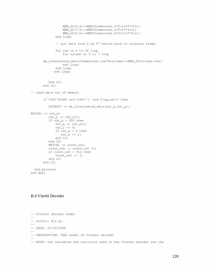
120
MEM_2D(2,k):=MEM(framecount,k*2+1+57*4+1);MEM_2D(7,k):=MEM(framecount,k*2+57*6+1);MEM_2D(3,k):=MEM(framecount,k*2+1+57*6+1);
end loop;
-- put data from 8 by 57 matrix back to original frame.
for row in 0 to 56 loopfor column in 0 to 7 loop
de_interleaved_data(framecount,row*8+column):=MEM_2D(column,row);end loop;
end loop;end loop;
end if;end if;
-- read data out of memory
if CLK2'EVENT and CLK2='1' and Flag_out=1 then
DATAOUT <= de_interleaved_data(out_x,out_y);
WATCH1 <= out_x;out_y := out_y+1;if out_y > 455 then
out_x := out_x+1;out_y := 0;if out_x > 2 then
out_x := 1;end if;
end if;WATCH2 <= count_out;count_out := count_out +1;if count_out > 912 then
count_out := 1;end if;
end if;
end process;end ALG;
B.4 Viterbi Decoder
-- Viterbi decoder model---- Author: Xin Qu---- DATE: 05/15/2000---- DESCRIPTION: VHDL model of Viterbi decoder---- NOTE: the variables and functions used in the Viterbi decoder are the
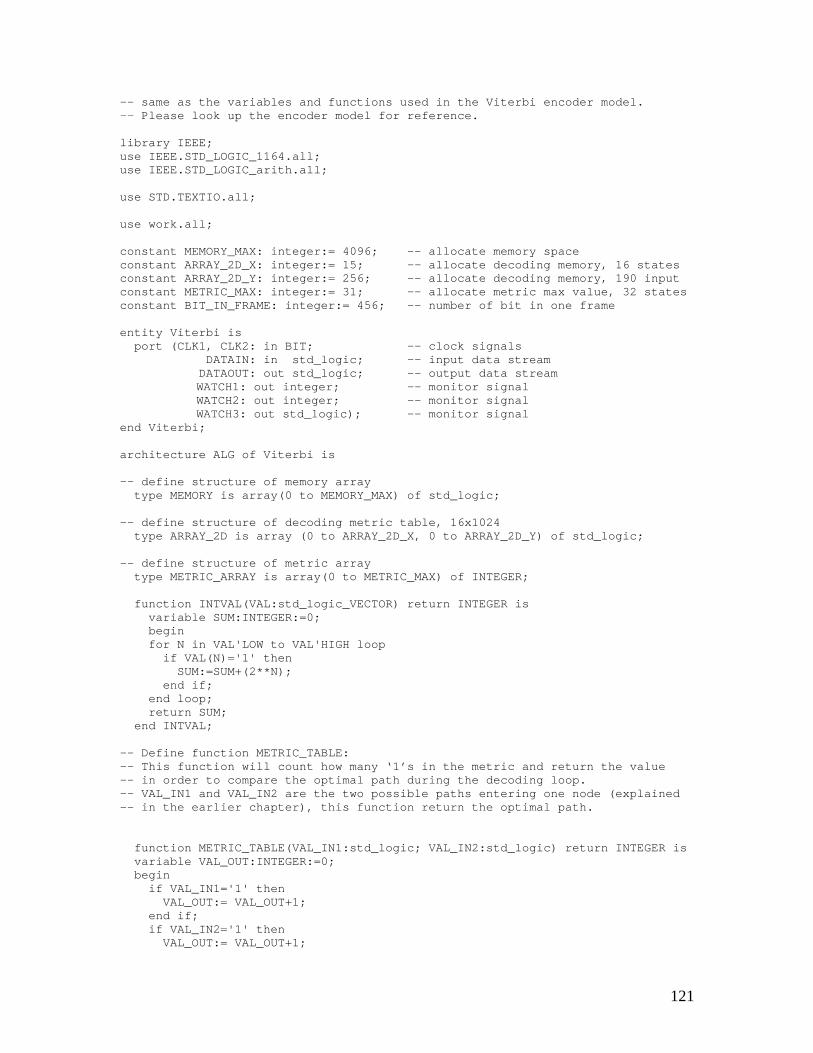
121
-- same as the variables and functions used in the Viterbi encoder model.-- Please look up the encoder model for reference.
library IEEE;use IEEE.STD_LOGIC_1164.all;use IEEE.STD_LOGIC_arith.all;
use STD.TEXTIO.all;
use work.all;
constant MEMORY_MAX: integer:= 4096; -- allocate memory spaceconstant ARRAY_2D_X: integer:= 15; -- allocate decoding memory, 16 statesconstant ARRAY_2D_Y: integer:= 256; -- allocate decoding memory, 190 inputconstant METRIC_MAX: integer:= 31; -- allocate metric max value, 32 statesconstant BIT_IN_FRAME: integer:= 456; -- number of bit in one frame
entity Viterbi isport (CLK1, CLK2: in BIT; -- clock signals
DATAIN: in std_logic; -- input data streamDATAOUT: out std_logic; -- output data streamWATCH1: out integer; -- monitor signalWATCH2: out integer; -- monitor signalWATCH3: out std_logic); -- monitor signal
end Viterbi;
architecture ALG of Viterbi is
-- define structure of memory arraytype MEMORY is array(0 to MEMORY_MAX) of std_logic;
-- define structure of decoding metric table, 16x1024type ARRAY_2D is array (0 to ARRAY_2D_X, 0 to ARRAY_2D_Y) of std_logic;
-- define structure of metric arraytype METRIC_ARRAY is array(0 to METRIC_MAX) of INTEGER;
function INTVAL(VAL:std_logic_VECTOR) return INTEGER isvariable SUM:INTEGER:=0;beginfor N in VAL'LOW to VAL'HIGH loop
if VAL(N)='1' thenSUM:=SUM+(2**N);
end if;end loop;return SUM;
end INTVAL;
-- Define function METRIC_TABLE:-- This function will count how many ‘1’s in the metric and return the value-- in order to compare the optimal path during the decoding loop.-- VAL_IN1 and VAL_IN2 are the two possible paths entering one node (explained-- in the earlier chapter), this function return the optimal path.
function METRIC_TABLE(VAL_IN1:std_logic; VAL_IN2:std_logic) return INTEGER isvariable VAL_OUT:INTEGER:=0;begin
if VAL_IN1='1' thenVAL_OUT:= VAL_OUT+1;
end if;if VAL_IN2='1' then
VAL_OUT:= VAL_OUT+1;
122
end if;return VAL_OUT;end METRIC_TABLE;
beginA1: process(CLK1, CLK2)
variable DATA_ARRAY, DATA_TEMP: ARRAY_2D;
-- declare memory variables for METRIC table using for decodingvariable metric, old_metric, temp_metric:
METRIC_ARRAY:=(0,0,0,0,0,0,0,0,0,0,0,0,0,0,0,0,0,0,0,0,0,0,0,0,0,0,0,0,0,0,0,0); -- the initial value of METRIC_ARRAY is all ‘0’s.
variable b, c: std_logic_VECTOR(0 to 1);variable k, j, l: integer; -- loop variable
variable MEM: MEMORY; -- define memory variablevariable ADDRESS1: std_logic_VECTOR(11 downto 0):="000000000000";variable ADDRESS2: std_logic_VECTOR(11 downto 0):="100000000000";
-- variables for input/output count, start delay count and flagsvariable start: integer:= 1;variable count_in: integer:= 1; -- count input bitsvariable count_out: integer:= 1; -- count output bitsvariable flag_in: integer:= 0; -- flag for input startvariable flag_out: integer:= 0; -- flag for output startvariable first: integer:= 5; -- delay for synchronize output with
input
variable p1, p2: std_logic; -- each time read two input bit fordecoding one output, p1 is the first input bit and p2 is the second one.
variable I: integer:= 1; -- counting which bit is the currentdecoding bit.
begin
-- read data into memory, the basic procedure is using in all the encoder/decod
if CLK1'EVENT and CLK1='1' thenMEM(INTVAL(ADDRESS1)+count_in) := DATAIN;
if count_in> BIT_IN_FRAME thenWATCH1 <= 1;
elseWATCH1 <= count_in;
end if;
-- delay start five clock cycle to synchronize with output
if first>0 thenfirst:=first-1;count_in:=count_in-1;
end if;
count_in := count_in + 1;start := start + 1;if start > BIT_IN_FRAME *11+5 then -- output delay for 11 frames
flag_out := 1;start := start+1;
end if;
123
if count_in >= 457 then -- got one frame, reset the count variablecount_in := 1;
-- initialize the metric tablefor j in 0 to 15 loop
old_metric(j):=0;end loop;
I := 1; -- variable for tracking the current bit in-- decoding procedure
-- decoding first two bits, refer to figure 4.10 and 4.11-- happens at t=1
-- according to the input value, setup the metric table
-- from figure 4.10 and 4.11, for the first two bit, there are two possibility;-- ‘00’ or ‘11’, the code below will count how many bits are different from the-- possible input. Ex, if p1=0 and p2=1, then the METRIC_TABLE(pa,p2)=1 which-- means there is one bit different from the possible input and will be stroe-- into the old_metric 0 position. Old_metric will keep tracking the 32 states-- (after comparing, 16 states will be kept and other 16 less possible states-- will be ignored). ADDRESS1+I indicates the current decoding bit that-- located in the input memory. If xor two different value, the result is ‘1’-- which mean there is a different bit. Old_metric is the metric from last step-- and temp metric is the current updated old_metric at current step.
p1 := MEM(INTVAL(ADDRESS1)+I) xor '0';p2 := MEM(INTVAL(ADDRESS1)+I+1) xor '0';old_metric(0):=old_metric(0)+METRIC_TABLE(p1,p2);p1 := MEM(INTVAL(ADDRESS1)+I) xor '1';p2 := MEM(INTVAL(ADDRESS1)+I+1) xor '1';old_metric(8):=old_metric(8)+METRIC_TABLE(p1,p2);temp_metric(0):=old_metric(0);temp_metric(8):=old_metric(8);
-- copy the decoded bit into output sequence in state 0 and 8DATA_ARRAY(0,0):='0';DATA_ARRAY(8,0):='1';
-- encoding next two bits, reference to chapter5 Viterbi decoder for detail-- happens at t=2. Refer to Figure 4.10 and 4.11.
-- according to the input value, setup the metric tableI := I+2;
-- compute partial path metric for the path into S0,(t=00)p1 := MEM(INTVAL(ADDRESS1)+I) xor '0';p2 := MEM(INTVAL(ADDRESS1)+I+1) xor '0';old_metric(0):=temp_metric(0)+METRIC_TABLE(p1,p2);
-- compute partial path metric for the path into S8,(t=11)p1 := MEM(INTVAL(ADDRESS1)+I) xor '1';p2 := MEM(INTVAL(ADDRESS1)+I+1) xor '1';old_metric(8):=temp_metric(0)+METRIC_TABLE(p1,p2);
-- compute partial path metric for the path into S4,(t=10)p1 := MEM(INTVAL(ADDRESS1)+I) xor '1';p2 := MEM(INTVAL(ADDRESS1)+I+1) xor '0';old_metric(4):=temp_metric(8)+METRIC_TABLE(p1,p2);
-- compute partial path metric for the path into S12,(t=01)p1 := MEM(INTVAL(ADDRESS1)+I) xor '0';p2 := MEM(INTVAL(ADDRESS1)+I+1) xor '1';old_metric(12):=temp_metric(8)+METRIC_TABLE(p1,p2);
-- store values in temp_metric for next set of calculations, this is necessary
124
-- because old_metric values are being updated at the same time that theircorrent values are being read.
temp_metric(0):=old_metric(0);temp_metric(8):=old_metric(8);temp_metric(4):=old_metric(4);temp_metric(12):=old_metric(12);
DATA_ARRAY(4,0):=DATA_ARRAY(8,0);DATA_ARRAY(4,1):='0';DATA_ARRAY(12,0):=DATA_ARRAY(8,0);DATA_ARRAY(12,1):='1';DATA_ARRAY(0,1):='0';DATA_ARRAY(8,0):=DATA_ARRAY(0,0);DATA_ARRAY(8,1):='1';
-- encoding next two bits, refer to Figure 4.10 and 4.11.-- happens at t=3
I := I+2;
-- according to the input value, setup the metric table
-- computation for branch into S0 and branch into S2 (t=00)p1 := MEM(INTVAL(ADDRESS1)+I) xor '0';p2 := MEM(INTVAL(ADDRESS1)+I+1) xor '0';old_metric(0):=temp_metric(0)+METRIC_TABLE(p1,p2);old_metric(2):=temp_metric(4)+METRIC_TABLE(p1,p2);
-- computation for branch into S8 and branch into S10 (t=11)p1 := MEM(INTVAL(ADDRESS1)+I) xor '1';p2 := MEM(INTVAL(ADDRESS1)+I+1) xor '1';old_metric(8):=temp_metric(0)+METRIC_TABLE(p1,p2);old_metric(10):=temp_metric(4)+METRIC_TABLE(p1,p2);
-- computation for branch into S4 and branch into S6 (t=10)p1 := MEM(INTVAL(ADDRESS1)+I) xor '1';p2 := MEM(INTVAL(ADDRESS1)+I+1) xor '0';old_metric(4):=temp_metric(8)+METRIC_TABLE(p1,p2);old_metric(6):=temp_metric(12)+METRIC_TABLE(p1,p2);
-- computation for branch into S12 and branch into S14 (t=01)p1 := MEM(INTVAL(ADDRESS1)+I) xor '0';p2 := MEM(INTVAL(ADDRESS1)+I+1) xor '1';old_metric(12):=temp_metric(8)+METRIC_TABLE(p1,p2);old_metric(14):=temp_metric(12)+METRIC_TABLE(p1,p2);
temp_metric(0):=old_metric(0);temp_metric(2):=old_metric(2);temp_metric(8):=old_metric(8);temp_metric(10):=old_metric(10);temp_metric(4):=old_metric(4);temp_metric(6):=old_metric(6);temp_metric(12):=old_metric(12);temp_metric(14):=old_metric(14);
-- update transmitted bits for each pathfor j in 0 to 1 loop
DATA_ARRAY(14,j):=DATA_ARRAY(12,j);DATA_ARRAY(6,j):=DATA_ARRAY(12,j);DATA_ARRAY(10,j):=DATA_ARRAY(4,j);DATA_ARRAY(2,j):=DATA_ARRAY(4,j);DATA_ARRAY(12,j):=DATA_ARRAY(8,j);DATA_ARRAY(4,j):=DATA_ARRAY(8,j);DATA_ARRAY(8,j):=DATA_ARRAY(0,j);
end loop;
125
DATA_ARRAY(0,2):='0';DATA_ARRAY(2,2):='0';DATA_ARRAY(4,2):='0';DATA_ARRAY(6,2):='0';DATA_ARRAY(8,2):='1';DATA_ARRAY(10,2):='1';DATA_ARRAY(12,2):='1';DATA_ARRAY(14,2):='1';
-- decoding next two bits, refer to Figure 4.10 and 4.11.-- happens at t=4
I := I+2;
-- according to the input value, setup the metric table
-- computation for branch into S0 S2 S9 S11 (t=00)p1 := MEM(INTVAL(ADDRESS1)+I) xor '0';p2 := MEM(INTVAL(ADDRESS1)+I+1) xor '0';old_metric(0):=temp_metric(0)+METRIC_TABLE(p1,p2);old_metric(2):=temp_metric(4)+METRIC_TABLE(p1,p2);old_metric(9):=temp_metric(2)+METRIC_TABLE(p1,p2);old_metric(11):=temp_metric(6)+METRIC_TABLE(p1,p2);
-- computation for branch into S1 S3 S8 S10 (t=11)p1 := MEM(INTVAL(ADDRESS1)+I) xor '1';p2 := MEM(INTVAL(ADDRESS1)+I+1) xor '1';old_metric(1):=temp_metric(2)+METRIC_TABLE(p1,p2);old_metric(3):=temp_metric(6)+METRIC_TABLE(p1,p2);old_metric(8):=temp_metric(0)+METRIC_TABLE(p1,p2);old_metric(10):=temp_metric(4)+METRIC_TABLE(p1,p2);
-- computation for branch into S4 S6 S13 S15 (t=10)p1 := MEM(INTVAL(ADDRESS1)+I) xor '1';p2 := MEM(INTVAL(ADDRESS1)+I+1) xor '0';old_metric(4):=temp_metric(8)+METRIC_TABLE(p1,p2);old_metric(6):=temp_metric(12)+METRIC_TABLE(p1,p2);old_metric(13):=temp_metric(10)+METRIC_TABLE(p1,p2);old_metric(15):=temp_metric(14)+METRIC_TABLE(p1,p2);
-- computation for branch into S5 S7 S12 S14 (t=01)p1 := MEM(INTVAL(ADDRESS1)+I) xor '0';p2 := MEM(INTVAL(ADDRESS1)+I+1) xor '1';old_metric(5):=temp_metric(10)+METRIC_TABLE(p1,p2);old_metric(7):=temp_metric(14)+METRIC_TABLE(p1,p2);old_metric(12):=temp_metric(8)+METRIC_TABLE(p1,p2);old_metric(14):=temp_metric(12)+METRIC_TABLE(p1,p2);
-- update metrictemp_metric(0):=old_metric(0);temp_metric(2):=old_metric(2);temp_metric(9):=old_metric(9);temp_metric(11):=old_metric(11);temp_metric(1):=old_metric(1);temp_metric(3):=old_metric(3);temp_metric(8):=old_metric(8);temp_metric(10):=old_metric(10);temp_metric(4):=old_metric(4);temp_metric(6):=old_metric(6);temp_metric(13):=old_metric(13);temp_metric(15):=old_metric(15);temp_metric(5):=old_metric(5);temp_metric(7):=old_metric(7);temp_metric(12):=old_metric(12);temp_metric(14):=old_metric(14);
-- update transmitted bits for each path
126
for j in 0 to 2 loopDATA_ARRAY(15,j):=DATA_ARRAY(14,j);DATA_ARRAY(7,j):=DATA_ARRAY(14,j);DATA_ARRAY(11,j):=DATA_ARRAY(6,j);DATA_ARRAY(3,j):=DATA_ARRAY(6,j);DATA_ARRAY(13,j):=DATA_ARRAY(10,j);DATA_ARRAY(5,j):=DATA_ARRAY(10,j);DATA_ARRAY(9,j):=DATA_ARRAY(2,j);DATA_ARRAY(1,j):=DATA_ARRAY(2,j);DATA_ARRAY(14,j):=DATA_ARRAY(12,j);DATA_ARRAY(6,j):=DATA_ARRAY(12,j);DATA_ARRAY(10,j):=DATA_ARRAY(4,j);DATA_ARRAY(2,j):=DATA_ARRAY(4,j);DATA_ARRAY(12,j):=DATA_ARRAY(8,j);DATA_ARRAY(4,j):=DATA_ARRAY(8,j);DATA_ARRAY(8,j):=DATA_ARRAY(0,j);
end loop;
for j in 0 to 7 loopDATA_ARRAY(j,3):='0';DATA_ARRAY(j+8,3):='1';
end loop;
-- encoding loop starts process the rest of bits-- encoding rest bits, refer to Figure 4.10 and 4.11.-- The correspondence between branches in Figure 4.10 and subscripts of array-- “metric”
l := 4; -- variable to indicate the number of transmitted-- bits for each path at each decoding step.
-- according to the input value, setup the metric table
for k in 0 to 182 loop-- because we already calculated four output bits, so the loop only need to run-- for 190-4=186 times, so the loop start from 0 to 182. The last four cycle-- from 186 to 189 will be decoded later.
I := I+2;p1 := MEM(INTVAL(ADDRESS1)+I) xor '0';p2 := MEM(INTVAL(ADDRESS1)+I+1) xor '0';
-- there are 32 branches between nodes at t=k-1 to nodes at t=k. The branches-- with corresponding to transmitted bits are numbered 0 to 15; those-- corresponding to transmitted bits of ‘,’ are numbered.
-- computation for branches with t=00
metric(0):=temp_metric(0)+METRIC_TABLE(p1,p2);metric(1):=temp_metric(3)+METRIC_TABLE(p1,p2);metric(2):=temp_metric(4)+METRIC_TABLE(p1,p2);metric(3):=temp_metric(7)+METRIC_TABLE(p1,p2);metric(8):=temp_metric(1)+METRIC_TABLE(p1,p2);metric(9):=temp_metric(2)+METRIC_TABLE(p1,p2);metric(10):=temp_metric(5)+METRIC_TABLE(p1,p2);metric(11):=temp_metric(6)+METRIC_TABLE(p1,p2);
-- computation for branches with t=11p1 := MEM(INTVAL(ADDRESS1)+I) xor '1';p2 := MEM(INTVAL(ADDRESS1)+I+1) xor '1';metric(0+16):=temp_metric(1)+METRIC_TABLE(p1,p2);metric(1+16):=temp_metric(2)+METRIC_TABLE(p1,p2);metric(2+16):=temp_metric(5)+METRIC_TABLE(p1,p2);
127
metric(3+16):=temp_metric(6)+METRIC_TABLE(p1,p2);metric(8+16):=temp_metric(0)+METRIC_TABLE(p1,p2);metric(9+16):=temp_metric(3)+METRIC_TABLE(p1,p2);metric(10+16):=temp_metric(4)+METRIC_TABLE(p1,p2);metric(11+16):=temp_metric(7)+METRIC_TABLE(p1,p2);
-- computation for branches with t=10p1 := MEM(INTVAL(ADDRESS1)+I) xor '1';p2 := MEM(INTVAL(ADDRESS1)+I+1) xor '0';metric(4):=temp_metric(8)+METRIC_TABLE(p1,p2);metric(5):=temp_metric(11)+METRIC_TABLE(p1,p2);metric(6):=temp_metric(12)+METRIC_TABLE(p1,p2);metric(7):=temp_metric(15)+METRIC_TABLE(p1,p2);metric(12):=temp_metric(9)+METRIC_TABLE(p1,p2);metric(13):=temp_metric(10)+METRIC_TABLE(p1,p2);metric(14):=temp_metric(13)+METRIC_TABLE(p1,p2);metric(15):=temp_metric(14)+METRIC_TABLE(p1,p2);
-- computation for branches with t=01p1 := MEM(INTVAL(ADDRESS1)+I) xor '0';p2 := MEM(INTVAL(ADDRESS1)+I+1) xor '1';metric(4+16):=temp_metric(9)+METRIC_TABLE(p1,p2);metric(5+16):=temp_metric(10)+METRIC_TABLE(p1,p2);metric(6+16):=temp_metric(13)+METRIC_TABLE(p1,p2);metric(7+16):=temp_metric(14)+METRIC_TABLE(p1,p2);metric(12+16):=temp_metric(8)+METRIC_TABLE(p1,p2);metric(13+16):=temp_metric(11)+METRIC_TABLE(p1,p2);metric(14+16):=temp_metric(12)+METRIC_TABLE(p1,p2);metric(15+16):=temp_metric(15)+METRIC_TABLE(p1,p2);
-- Compare the 16 optimal paths from the total 32 possible paths
for j in 0 to 15 loopfor k in 0 to l-1 loop
DATA_TEMP(j,k):=DATA_ARRAY(j,k);end loop;if metric(j) <= metric(j+16) then
temp_metric(j):=metric(j);else
temp_metric(j):=metric(j+16);end if;
end loop;
-- compare the better path from the two path available from single node, choose-- the better one with less value in metric table. Totally 32 paths need to be-- compared to choose 16 out of them. Update transmitted data.
if metric(0) <= metric(0+16) thenfor k in 0 to l-1 loop
DATA_ARRAY(0,k):=DATA_TEMP(0,k);end loop;
elsefor k in 0 to l-1 loop
DATA_ARRAY(0,k):=DATA_TEMP(1,k);end loop;
end if;if metric(1) <= metric(1+16) then
for k in 0 to l-1 loopDATA_ARRAY(1,k):=DATA_TEMP(3,k);
end loop;else
for k in 0 to l-1 loopDATA_ARRAY(1,k):=DATA_TEMP(2,k);
end loop;end if;
128
if metric(2) <= metric(2+16) thenfor k in 0 to l-1 loop
DATA_ARRAY(2,k):=DATA_TEMP(4,k);end loop;
elsefor k in 0 to l-1 loop
DATA_ARRAY(2,k):=DATA_TEMP(5,k);end loop;
end if;if metric(3) <= metric(3+16) then
for k in 0 to l-1 loopDATA_ARRAY(3,k):=DATA_TEMP(7,k);
end loop;else
for k in 0 to l-1 loopDATA_ARRAY(3,k):=DATA_TEMP(6,k);
end loop;end if;if metric(4) <= metric(4+16) then
for k in 0 to l-1 loopDATA_ARRAY(4,k):=DATA_TEMP(8,k);
end loop;else
for k in 0 to l-1 loopDATA_ARRAY(4,k):=DATA_TEMP(9,k);
end loop;end if;if metric(5) <= metric(5+16) then
for k in 0 to l-1 loopDATA_ARRAY(5,k):=DATA_TEMP(11,k);
end loop;else
for k in 0 to l-1 loopDATA_ARRAY(5,k):=DATA_TEMP(10,k);
end loop;end if;if metric(6) <= metric(6+16) then
for k in 0 to l-1 loopDATA_ARRAY(6,k):=DATA_TEMP(12,k);
end loop;else
for k in 0 to l-1 loopDATA_ARRAY(6,k):=DATA_TEMP(13,k);
end loop;end if;if metric(7) <= metric(7+16) then
for k in 0 to l-1 loopDATA_ARRAY(7,k):=DATA_TEMP(15,k);
end loop;else
for k in 0 to l-1 loopDATA_ARRAY(7,k):=DATA_TEMP(14,k);
end loop;end if;if metric(8) <= metric(8+16) then
for k in 0 to l-1 loopDATA_ARRAY(8,k):=DATA_TEMP(1,k);
end loop;else
for k in 0 to l-1 loopDATA_ARRAY(8,k):=DATA_TEMP(0,k);
end loop;end if;
129
if metric(9) <= metric(9+16) thenfor k in 0 to l-1 loop
DATA_ARRAY(9,k):=DATA_TEMP(2,k);end loop;
elsefor k in 0 to l-1 loop
DATA_ARRAY(9,k):=DATA_TEMP(3,k);end loop;
end if;if metric(10) <= metric(10+16) then
for k in 0 to l-1 loopDATA_ARRAY(10,k):=DATA_TEMP(5,k);
end loop;else
for k in 0 to l-1 loopDATA_ARRAY(10,k):=DATA_TEMP(4,k);
end loop;if metric(11) <= metric(11+16) then
for k in 0 to l-1 loopDATA_ARRAY(11,k):=DATA_TEMP(6,k);
end loop;else
for k in 0 to l-1 loopDATA_ARRAY(11,k):=DATA_TEMP(7,k);
end loop;end if;if metric(12) <= metric(12+16) then
for k in 0 to l-1 loopDATA_ARRAY(12,k):=DATA_TEMP(9,k);
end loop;else
for k in 0 to l-1 loopDATA_ARRAY(12,k):=DATA_TEMP(8,k);
end loop;end if;if metric(13) <= metric(13+16) then
for k in 0 to l-1 loopDATA_ARRAY(13,k):=DATA_TEMP(10,k);
end loop;else
for k in 0 to l-1 loopDATA_ARRAY(13,k):=DATA_TEMP(11,k);
end loop;end if;if metric(14) <= metric(14+16) then
for k in 0 to l-1 loopDATA_ARRAY(14,k):=DATA_TEMP(13,k);
end loop;else
for k in 0 to l-1 loopDATA_ARRAY(14,k):=DATA_TEMP(12,k);
end loop;end if;if metric(15) <= metric(15+16) then
for k in 0 to l-1 loopDATA_ARRAY(15,k):=DATA_TEMP(14,k);
end loop;-- else, DATA_ARRAY(15,k):=DATA_TEMP(15,k), no change!!!end if;
for j in 0 to 7 loopDATA_ARRAY(j,l):='0';DATA_ARRAY(j+8,l):='1';
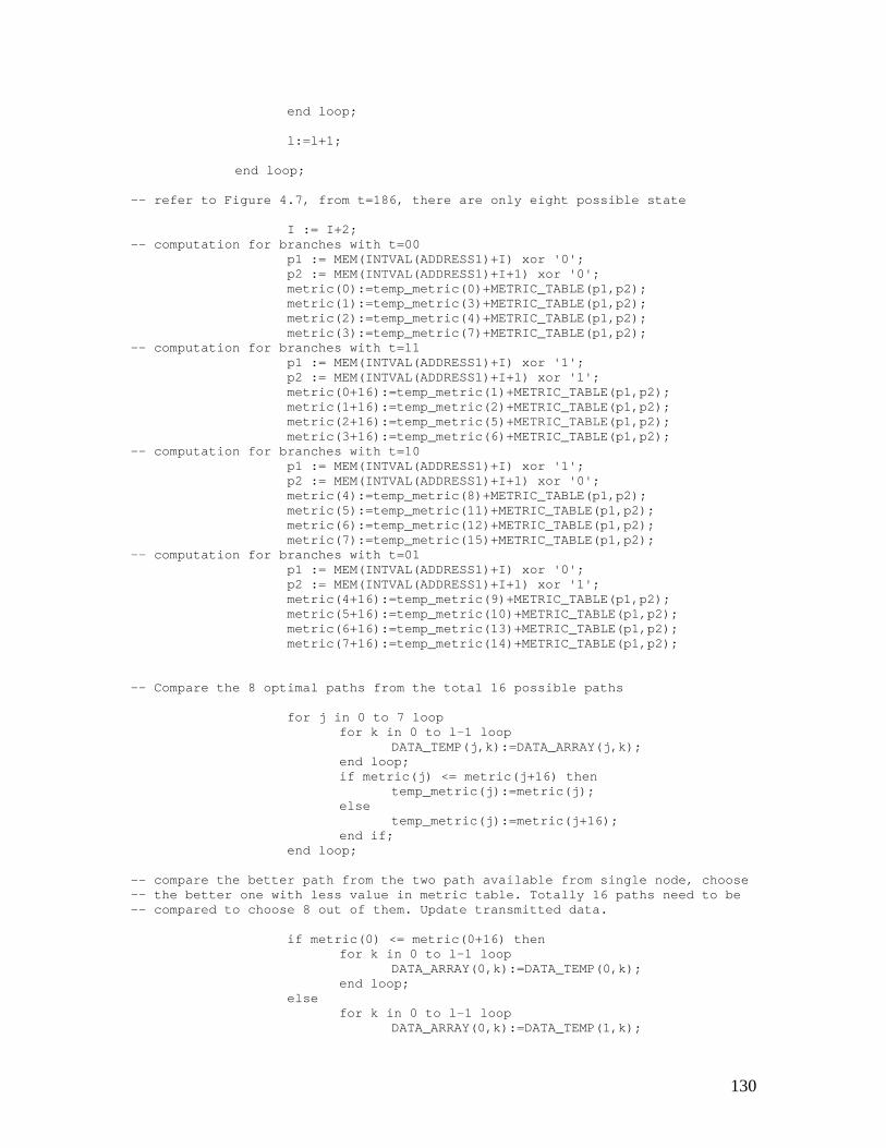
130
end loop;
l:=l+1;
end loop;
-- refer to Figure 4.7, from t=186, there are only eight possible state
I := I+2;-- computation for branches with t=00
p1 := MEM(INTVAL(ADDRESS1)+I) xor '0';p2 := MEM(INTVAL(ADDRESS1)+I+1) xor '0';metric(0):=temp_metric(0)+METRIC_TABLE(p1,p2);metric(1):=temp_metric(3)+METRIC_TABLE(p1,p2);metric(2):=temp_metric(4)+METRIC_TABLE(p1,p2);metric(3):=temp_metric(7)+METRIC_TABLE(p1,p2);
-- computation for branches with t=11p1 := MEM(INTVAL(ADDRESS1)+I) xor '1';p2 := MEM(INTVAL(ADDRESS1)+I+1) xor '1';metric(0+16):=temp_metric(1)+METRIC_TABLE(p1,p2);metric(1+16):=temp_metric(2)+METRIC_TABLE(p1,p2);metric(2+16):=temp_metric(5)+METRIC_TABLE(p1,p2);metric(3+16):=temp_metric(6)+METRIC_TABLE(p1,p2);
-- computation for branches with t=10p1 := MEM(INTVAL(ADDRESS1)+I) xor '1';p2 := MEM(INTVAL(ADDRESS1)+I+1) xor '0';metric(4):=temp_metric(8)+METRIC_TABLE(p1,p2);metric(5):=temp_metric(11)+METRIC_TABLE(p1,p2);metric(6):=temp_metric(12)+METRIC_TABLE(p1,p2);metric(7):=temp_metric(15)+METRIC_TABLE(p1,p2);
-- computation for branches with t=01p1 := MEM(INTVAL(ADDRESS1)+I) xor '0';p2 := MEM(INTVAL(ADDRESS1)+I+1) xor '1';metric(4+16):=temp_metric(9)+METRIC_TABLE(p1,p2);metric(5+16):=temp_metric(10)+METRIC_TABLE(p1,p2);metric(6+16):=temp_metric(13)+METRIC_TABLE(p1,p2);metric(7+16):=temp_metric(14)+METRIC_TABLE(p1,p2);
-- Compare the 8 optimal paths from the total 16 possible paths
for j in 0 to 7 loopfor k in 0 to l-1 loop
DATA_TEMP(j,k):=DATA_ARRAY(j,k);end loop;if metric(j) <= metric(j+16) then
temp_metric(j):=metric(j);else
temp_metric(j):=metric(j+16);end if;
end loop;
-- compare the better path from the two path available from single node, choose-- the better one with less value in metric table. Totally 16 paths need to be-- compared to choose 8 out of them. Update transmitted data.
if metric(0) <= metric(0+16) thenfor k in 0 to l-1 loop
DATA_ARRAY(0,k):=DATA_TEMP(0,k);end loop;
elsefor k in 0 to l-1 loop
DATA_ARRAY(0,k):=DATA_TEMP(1,k);
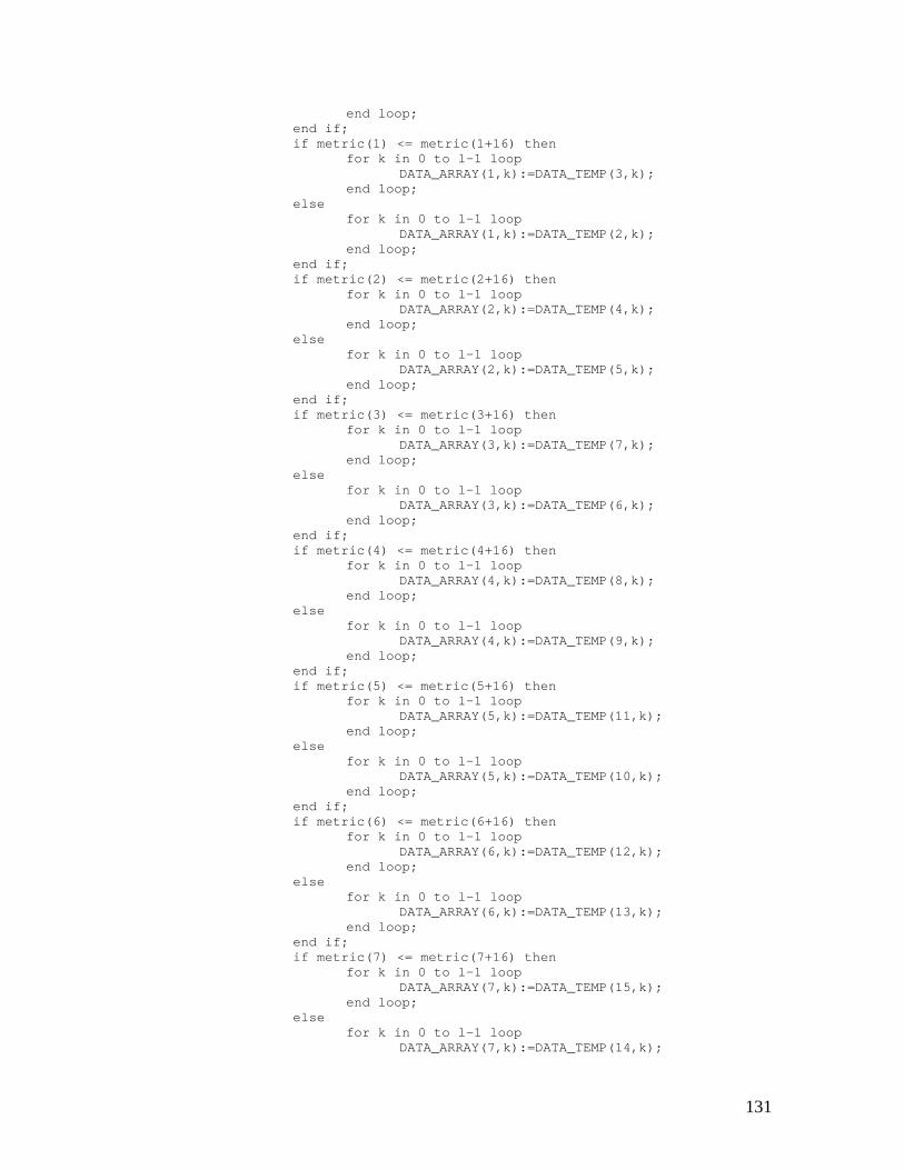
131
end loop;end if;if metric(1) <= metric(1+16) then
for k in 0 to l-1 loopDATA_ARRAY(1,k):=DATA_TEMP(3,k);
end loop;else
for k in 0 to l-1 loopDATA_ARRAY(1,k):=DATA_TEMP(2,k);
end loop;end if;if metric(2) <= metric(2+16) then
for k in 0 to l-1 loopDATA_ARRAY(2,k):=DATA_TEMP(4,k);
end loop;else
for k in 0 to l-1 loopDATA_ARRAY(2,k):=DATA_TEMP(5,k);
end loop;end if;if metric(3) <= metric(3+16) then
for k in 0 to l-1 loopDATA_ARRAY(3,k):=DATA_TEMP(7,k);
end loop;else
for k in 0 to l-1 loopDATA_ARRAY(3,k):=DATA_TEMP(6,k);
end loop;end if;if metric(4) <= metric(4+16) then
for k in 0 to l-1 loopDATA_ARRAY(4,k):=DATA_TEMP(8,k);
end loop;else
for k in 0 to l-1 loopDATA_ARRAY(4,k):=DATA_TEMP(9,k);
end loop;end if;if metric(5) <= metric(5+16) then
for k in 0 to l-1 loopDATA_ARRAY(5,k):=DATA_TEMP(11,k);
end loop;else
for k in 0 to l-1 loopDATA_ARRAY(5,k):=DATA_TEMP(10,k);
end loop;end if;if metric(6) <= metric(6+16) then
for k in 0 to l-1 loopDATA_ARRAY(6,k):=DATA_TEMP(12,k);
end loop;else
for k in 0 to l-1 loopDATA_ARRAY(6,k):=DATA_TEMP(13,k);
end loop;end if;if metric(7) <= metric(7+16) then
for k in 0 to l-1 loopDATA_ARRAY(7,k):=DATA_TEMP(15,k);
end loop;else
for k in 0 to l-1 loopDATA_ARRAY(7,k):=DATA_TEMP(14,k);
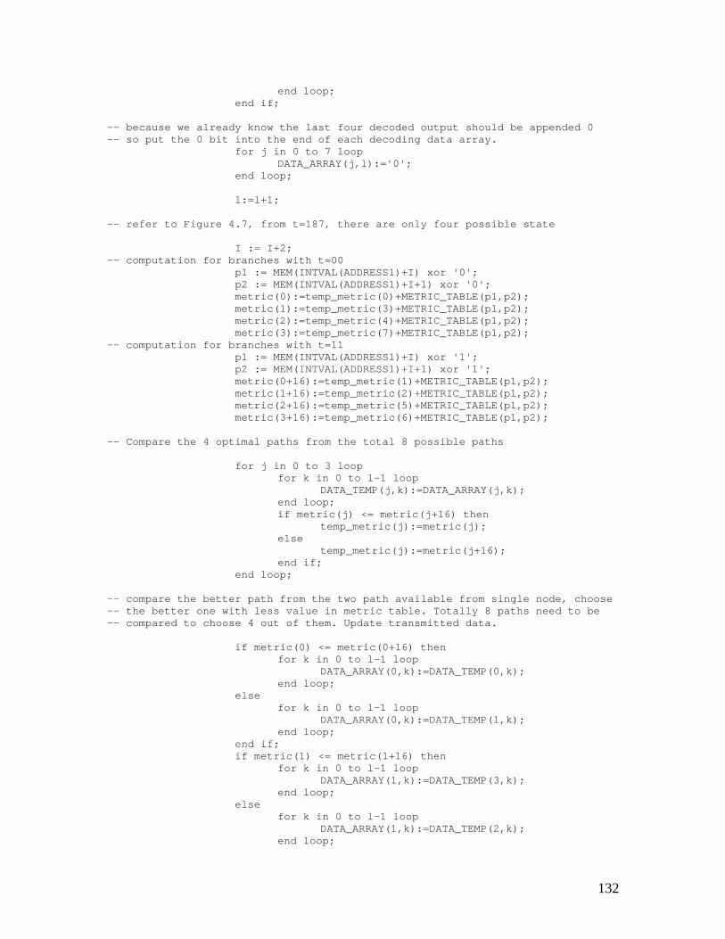
132
end loop;end if;
-- because we already know the last four decoded output should be appended 0-- so put the 0 bit into the end of each decoding data array.
for j in 0 to 7 loopDATA_ARRAY(j,l):='0';
end loop;
l:=l+1;
-- refer to Figure 4.7, from t=187, there are only four possible state
I := I+2;-- computation for branches with t=00
p1 := MEM(INTVAL(ADDRESS1)+I) xor '0';p2 := MEM(INTVAL(ADDRESS1)+I+1) xor '0';metric(0):=temp_metric(0)+METRIC_TABLE(p1,p2);metric(1):=temp_metric(3)+METRIC_TABLE(p1,p2);metric(2):=temp_metric(4)+METRIC_TABLE(p1,p2);metric(3):=temp_metric(7)+METRIC_TABLE(p1,p2);
-- computation for branches with t=11p1 := MEM(INTVAL(ADDRESS1)+I) xor '1';p2 := MEM(INTVAL(ADDRESS1)+I+1) xor '1';metric(0+16):=temp_metric(1)+METRIC_TABLE(p1,p2);metric(1+16):=temp_metric(2)+METRIC_TABLE(p1,p2);metric(2+16):=temp_metric(5)+METRIC_TABLE(p1,p2);metric(3+16):=temp_metric(6)+METRIC_TABLE(p1,p2);
-- Compare the 4 optimal paths from the total 8 possible paths
for j in 0 to 3 loopfor k in 0 to l-1 loop
DATA_TEMP(j,k):=DATA_ARRAY(j,k);end loop;if metric(j) <= metric(j+16) then
temp_metric(j):=metric(j);else
temp_metric(j):=metric(j+16);end if;
end loop;
-- compare the better path from the two path available from single node, choose-- the better one with less value in metric table. Totally 8 paths need to be-- compared to choose 4 out of them. Update transmitted data.
if metric(0) <= metric(0+16) thenfor k in 0 to l-1 loop
DATA_ARRAY(0,k):=DATA_TEMP(0,k);end loop;
elsefor k in 0 to l-1 loop
DATA_ARRAY(0,k):=DATA_TEMP(1,k);end loop;
end if;if metric(1) <= metric(1+16) then
for k in 0 to l-1 loopDATA_ARRAY(1,k):=DATA_TEMP(3,k);
end loop;else
for k in 0 to l-1 loopDATA_ARRAY(1,k):=DATA_TEMP(2,k);
end loop;
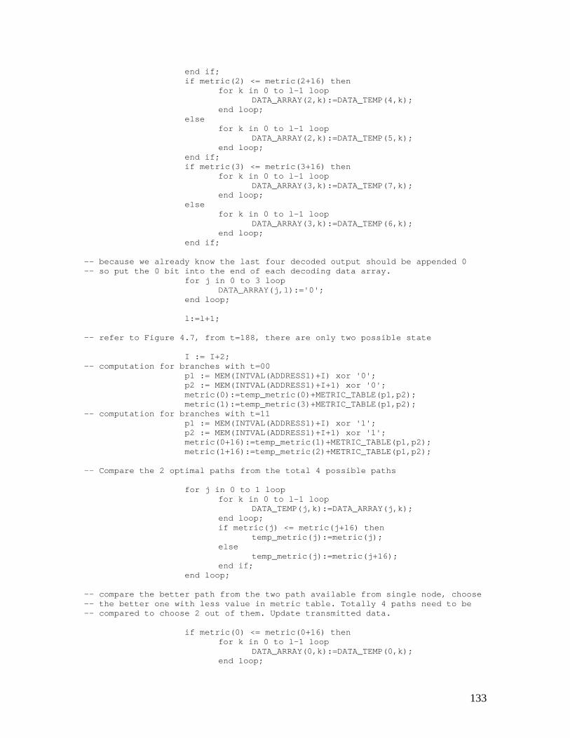
133
end if;if metric(2) <= metric(2+16) then
for k in 0 to l-1 loopDATA_ARRAY(2,k):=DATA_TEMP(4,k);
end loop;else
for k in 0 to l-1 loopDATA_ARRAY(2,k):=DATA_TEMP(5,k);
end loop;end if;if metric(3) <= metric(3+16) then
for k in 0 to l-1 loopDATA_ARRAY(3,k):=DATA_TEMP(7,k);
end loop;else
for k in 0 to l-1 loopDATA_ARRAY(3,k):=DATA_TEMP(6,k);
end loop;end if;
-- because we already know the last four decoded output should be appended 0-- so put the 0 bit into the end of each decoding data array.
for j in 0 to 3 loopDATA_ARRAY(j,l):='0';
end loop;
l:=l+1;
-- refer to Figure 4.7, from t=188, there are only two possible state
I := I+2;-- computation for branches with t=00
p1 := MEM(INTVAL(ADDRESS1)+I) xor '0';p2 := MEM(INTVAL(ADDRESS1)+I+1) xor '0';metric(0):=temp_metric(0)+METRIC_TABLE(p1,p2);metric(1):=temp_metric(3)+METRIC_TABLE(p1,p2);
-- computation for branches with t=11p1 := MEM(INTVAL(ADDRESS1)+I) xor '1';p2 := MEM(INTVAL(ADDRESS1)+I+1) xor '1';metric(0+16):=temp_metric(1)+METRIC_TABLE(p1,p2);metric(1+16):=temp_metric(2)+METRIC_TABLE(p1,p2);
-- Compare the 2 optimal paths from the total 4 possible paths
for j in 0 to 1 loopfor k in 0 to l-1 loop
DATA_TEMP(j,k):=DATA_ARRAY(j,k);end loop;if metric(j) <= metric(j+16) then
temp_metric(j):=metric(j);else
temp_metric(j):=metric(j+16);end if;
end loop;
-- compare the better path from the two path available from single node, choose-- the better one with less value in metric table. Totally 4 paths need to be-- compared to choose 2 out of them. Update transmitted data.
if metric(0) <= metric(0+16) thenfor k in 0 to l-1 loop
DATA_ARRAY(0,k):=DATA_TEMP(0,k);end loop;
134
elsefor k in 0 to l-1 loop
DATA_ARRAY(0,k):=DATA_TEMP(1,k);end loop;
end if;if metric(1) <= metric(1+16) then
for k in 0 to l-1 loopDATA_ARRAY(1,k):=DATA_TEMP(3,k);
end loop;else
for k in 0 to l-1 loopDATA_ARRAY(1,k):=DATA_TEMP(2,k);
end loop;end if;
-- because we already know the last four decoded output should be appended 0-- so put the 0 bit into the end of each decoding data array.
for j in 0 to 1 loopDATA_ARRAY(j,l):='0';
end loop;
l:=l+1;
-- refer to Figure 4.7, from t=189, there are only one possible state S0
I := I+2;-- computation for branches with t=00
p1 := MEM(INTVAL(ADDRESS1)+I) xor '0';p2 := MEM(INTVAL(ADDRESS1)+I+1) xor '0';metric(0):=temp_metric(0)+METRIC_TABLE(p1,p2);
-- computation for branches with t=11p1 := MEM(INTVAL(ADDRESS1)+I) xor '1';p2 := MEM(INTVAL(ADDRESS1)+I+1) xor '1';metric(0+16):=temp_metric(1)+METRIC_TABLE(p1,p2);
-- Compare the 1 optimal paths from the total 2 possible paths
for k in 0 to l-1 loopDATA_TEMP(0,k):=DATA_ARRAY(0,k);
end loop;if metric(0) <= metric(0+16) then
temp_metric(0):=metric(0);else
temp_metric(0):=metric(0+16);end if;
-- compare the better path from the two path available from single node, choose-- the better one with less value in metric table. Totally 2 paths need to be-- compared to choose 1 out of them. Update transmitted data.
if metric(0) <= metric(0+16) thenfor k in 0 to l-1 loop
DATA_ARRAY(0,k):=DATA_TEMP(0,k);end loop;
elsefor k in 0 to l-1 loop
DATA_ARRAY(0,k):=DATA_TEMP(1,k);end loop;
end if;
-- because we already know the last four decoded output should be appended 0-- so put the 0 bit into the end of each decoding data array.
DATA_ARRAY(0,l):='0';
135
l:=l+1;
-- so until now, the data sequence saved in metric(0) is the optimal decoding-- sequence.
-- save unprotected class II bits
for k in 379 to 456 loopMEM(INTVAL(ADDRESS2)+k-189) := MEM(INTVAL(ADDRESS1)+k);
end loop;
end if;end if; -- end of CLK1 event
-- read data out of memory, output from the optimal path data stream.
if CLK2'EVENT and CLK2='1' and Flag_out=1 then
if count_out<190 thenDATAOUT <= DATA_ARRAY(0,count_out-1);
elseDATAOUT <= MEM(INTVAL(ADDRESS2)+count_out);
end if;
WATCH2 <= count_out;
count_out := count_out + 1;if count_out > 267 then
count_out := 1;end if;
end if;
end process;end ALG;
B.5 Parity Check Decoder
-- Parity check decoder model---- Author: Xin Qu---- DATE: 3/12/00---- DESCRIPTION: This is Parity decoder VHDL model---- NOTE: the variables and functions used in the parity check decoder are the-- same as the variables and functions used in the parity encoder model.-- Please look up the encoder model for reference.--
library IEEE;use IEEE.STD_LOGIC_1164.all;use IEEE.STD_LOGIC_arith.all;
use STD.TEXTIO.all;
use work.all;
constant MEM_SIZE: integer:= 2047;
136
constant FRAME_SIZE: integer:= 267;constant CLASS1a: integer:= 50;constant CLASS2: integer:= 186;constant PARITY: integer:= 92;constant OUT_FRAME_SIZE: integer: 260;
entity ParityCheck isport (CLK1, CLK2: in BIT; -- clock 1 and clock 2
DATAIN: in std_logic; -- Input data streamDATAOUT: out std_logic; -- Output data streamWATCH1: out integer; -- monitor signalWATCH2: out integer); -- monitor signal
end ParityCheck;
architecture ALG of ParityCheck istype MEMORY is array(0 to MEM_SIZE) of std_logic;-- locate memory for data
proces
-- function INTVAL counts how many bit ‘1’ in the data stream
function INTVAL(VAL:std_logic_VECTOR) return INTEGER isvariable SUM:INTEGER:=0;begin
-- count from lowest bit to highest bit tofor N in VAL'LOW to VAL'HIGH loop
if VAL(N)='1' thenSUM:=SUM+(2**N);
end if;end loop;return SUM;
end INTVAL;
-- calculate remainder devided by 2
function REMD(VAL:std_logic) return std_logic isbegin
if VAL='1' thenreturn '0';
elsereturn '1';
end if;end REMD;
beginA1: process(CLK1, CLK2)
variable MEM, MEM_TEMP: MEMORY; -- memory variable-- memory address variablevariable ADDRESS1: std_logic_VECTOR(10 downto 0):="00000000000";variable ADDRESS2: std_logic_VECTOR(10 downto 0):="10000000000";variable ADDRESS: std_logic_VECTOR(10 downto 0);variable p0, p1, p2, p_tem, p_temi: std_logic;variable start: integer:= 1; -- start pointvariable count_in: integer:= 1; -- count for input datavariable count_out: integer:= 1; -- count for output datavariable Flag_in: integer:= 0; -- flag variable for input datavariable Flag_out: integer:= 0; -- flag variable for output datavariable first: integer:= 4; -- count for output delay
variable vout: std_logic; -- variable for writing output log filefile output: text is out "final.out"; -- output log filevariable lout: line; -- variable for writing output log file
begin
137
-- store data into memory
if CLK1'EVENT and CLK1='1' thenMEM(INTVAL(ADDRESS1)+count_in) := DATAIN;
WATCH1 <= count_in;
-- delay start four clock cycle to synchronize with the input data
if first>0 thenfirst:=first-1;count_in:=count_in-1;
end if;
count_in := count_in + 1;start := start + 1;if start > FRAME_SIZE *12+5 then -- output delay for 12 frame
flag_out := 1;start := start+1;
end if;if count_in > FRAME_SIZE then -- got one frame at this point
count_in := 1;
-- re-ordering frame bits (Class 1 bits)
for I in 1 to PARITY-1 loopMEM(INTVAL(ADDRESS2)+(2*(I-1)+1)) := MEM(INTVAL(ADDRESS1)+I);MEM(INTVAL(ADDRESS2)+2*I) := MEM(INTVAL(ADDRESS1)+ CLASS2-I);end loop;
-- add "Class II" bits
for I in CLASS2+4 to FRAME_SIZE loopMEM(INTVAL(ADDRESS2)+I-7) := MEM(INTVAL(ADDRESS1)+I);end loop;
-- calculate parity bits
p0 := '0';p1 := '0';p2 := '0';p_tem := '0';
for I in 1 to CLASS1a loopp_tem := MEM(INTVAL(ADDRESS2)+I) xor p2;p2 := p1;p1 := p_tem xor p0;p0 := p_tem;end loop;
-- check parity bits, compare the re-calculate parity bits with the parity-- bits received, output warning if they don’t match.
if Flag_out=1 thenassert (REMD(p0)=MEM(INTVAL(ADDRESS1)+94))
report "ParityCheck: Error(94)!"severity WARNING;
assert (REMD(p1)=MEM(INTVAL(ADDRESS1)+93))report "ParityCheck: Error(93)!"severity WARNING;
assert (REMD(p2)=MEM(INTVAL(ADDRESS1)+92))report "ParityCheck: Error(92)!"
138
severity WARNING;end if;
end if;end if;
-- read data out of memory
if CLK2'EVENT and CLK2='1' and Flag_out=1 then
DATAOUT <= MEM(INTVAL(ADDRESS2)+count_out);
-- write output file
vout := MEM(INTVAL(ADDRESS2)+count_out);WRITE(lout, To_bit(vout));WRITELINE(output, lout);
WATCH2 <= count_out;count_out := count_out +1;if count_out > OUT_FRAME_SIZE then
count_out := 1;end if;
end if;
end process;end ALG;
139
Appendix C: VHDL code for channel models
C.1 Random Error Channel Model
-- Random error Channel model---- Author: Xin Qu---- DATE: 2-18-00---- DESCRIPTION: VHDL random error channel model-- The IEEE.math.real library is included in this model for the random number-- function. “GET_RAND_MAX” will return the maximum range of the random number-- that generates by the computer. Each time calls the “RAND” function will-- return a random number. And “SRAND” function setup the initial seed.
library IEEE;use IEEE.STD_LOGIC_1164.all;use IEEE.STD_LOGIC_arith.all;use IEEE.math_real.all;use STD.TEXTIO.all;use work.all;
-- TIME: error probability; DURATION: error duration; seed: initial seed-- R1, R1: monitor signals
entity Channel isport ( CLK: in BIT; --clock signal
PROB: in integer := 0; -- error probabilityDURATION: in integer; -- error duration
DATAIN: in std_logic; -- input data streamDATAOUT: out std_logic; -- output data stream
seed: in integer := 1; -- seed (any integer between 1 to 5-- digits)
R1: out integer; -- monitor input bit index for debug
140
R2: out integer ); -- monitor output bit index for debugend Channel;
architecture ALG of Channel is
beginprocess(CLK, TIME, DURATION)variable R: integer; -- random error probabilityvariable RAN_DUR: integer; -- random error durationvariable DURATION_FLAG: integer:= 0; -- when error occurs, indicate
the duration of the errorvariable ttt: integer; -- temporary variablevariable vin: std_logic; -- variable of writing log filevariable vout: std_logic; -- variable of writing log filefile input: text is out "channel.in";file output: text is out "channel.out";variable lin: line; -- variable of writing log filevariable lout: line; -- variable of writing log file
variable P: integer; -- central point of the algorithm,-- refer chapter 5 for detail explanation of the algorithm
variable seed_flag : integer := 1; -- flag of seed input
begin
-- create random seedif CLK'EVENT and seed_flag=1 then
ttt := SRAND(seed); -- setup initial seed for random functionseed_flag := 0;
end if;
-- The algorithm used below is the generate random error in the channel model,-- the details of the implementation of the algorithm is explained in the-- previous chapter of channel model.
if CLK'EVENT and CLK='1' then
-- DURATIONFLAG variable initial to 0, if there is error, the FLAG–- variabl is set to the duration of the error. As each successive-- bit enters the channel FLAG is decremented. Each bit becomes an-- error bit until FLAG decrements to 0. When FLAG reaches 0, as-- each new bit enters the channel, a decision is made as to-- whether a new error burst should begin based on a random-- process.
if DURATION_FLAG<1 thenR:=RAND;R1 <= RAN_PROB; -- monitor-- P=random/MAX*PROB-- P=random/10000*PROB for 0.01% error rate-- P=random/100000*PROB for 0.001% rate-- etc...P := GET_RAND_MAX/10000*PROB;R2 <= P;if R<P then -- bit error happens
DURATION_FLAG := DURATION - 1;R2 <= P; -- monitorDATAOUT <= not DATAIN; -- create an error bitvin := DATAIN; -- for file outputvout := not DATAIN;WRITE(lin, To_bit(vin));WRITELINE(input, lin);WRITE(lout, To_bit(vout));
141
WRITELINE(output, lout);else -- there is no bit error
DATAOUT <= DATAIN; -- copy input to outputvin := DATAIN; -- for file outputvout := DATAIN;WRITE(lin, To_bit(vin));WRITELINE(input, lin);WRITE(lout, To_bit(vout));WRITELINE(output, lout);
end if;else -- bit error happens because the current error
-- burst has not yet finishedDATAOUT <= not DATAIN; -- create an error bitvin := DATAIN; -- for file outputvout := not DATAIN;WRITE(lin, To_bit(vin));
WRITELINE(input, lin);WRITE(lout, To_bit(vout));WRITELINE(output, lout);DURATION_FLAG := DURATION_FLAG - 1; -- update the
-- duration flag-- R2 <= DURATION_FLAG; -- monitor
end if;end if;
end process;end ALG;
C.2 Burst Error Channel Model
-- Burst Channel model---- Author: Xin Qu---- DATE: 2-18-00---- DESCRIPTION: VHDL model for burst error channel--
library IEEE;use IEEE.STD_LOGIC_1164.all;use IEEE.STD_LOGIC_arith.all;use IEEE.math_real.all;use STD.TEXTIO.all;
use work.all;
-- TIME: error probability; DURATION: error duration; seed: initial seed-- R1, R1: monitor signals
constant DELAY: integer:= 3556; -- delay to synchronize with input-- delay for 6 frame of data and 4 bits-- for synchronization
entity Channel is
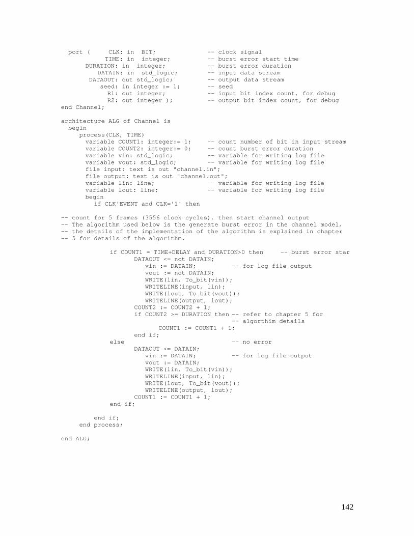
142
port ( CLK: in BIT; -- clock signalTIME: in integer; -- burst error start time
DURATION: in integer; -- burst error durationDATAIN: in std_logic; -- input data stream
DATAOUT: out std_logic; -- output data streamseed: in integer := 1; -- seed
R1: out integer; -- input bit index count, for debugR2: out integer ); -- output bit index count, for debug
end Channel;
architecture ALG of Channel isbegin
process(CLK, TIME)variable COUNT1: integer:= 1; -- count number of bit in input streamvariable COUNT2: integer:= 0; -- count burst error durationvariable vin: std_logic; -- variable for writing log filevariable vout: std_logic; -- variable for writing log filefile input: text is out "channel.in";file output: text is out "channel.out";variable lin: line; -- variable for writing log filevariable lout: line; -- variable for writing log filebegin
if CLK'EVENT and CLK='1' then
-- count for 5 frames (3556 clock cycles), then start channel output-- The algorithm used below is the generate burst error in the channel model,-- the details of the implementation of the algorithm is explained in chapter-- 5 for details of the algorithm.
if COUNT1 = TIME+DELAY and DURATION>0 then -- burst error starDATAOUT <= not DATAIN;
vin := DATAIN; -- for log file outputvout := not DATAIN;WRITE(lin, To_bit(vin));WRITELINE(input, lin);WRITE(lout, To_bit(vout));WRITELINE(output, lout);
COUNT2 := COUNT2 + 1;if COUNT2 >= DURATION then -- refer to chapter 5 for
-- algorthim detailsCOUNT1 := COUNT1 + 1;
end if;else -- no error
DATAOUT <= DATAIN;vin := DATAIN; -- for log file outputvout := DATAIN;WRITE(lin, To_bit(vin));WRITELINE(input, lin);WRITE(lout, To_bit(vout));WRITELINE(output, lout);
COUNT1 := COUNT1 + 1;end if;
end if;end process;
end ALG;
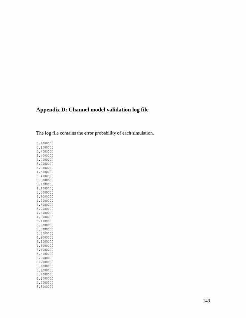
143
Appendix D: Channel model validation log file
The log file contains the error probability of each simulation.
5.6000006.1000005.4000005.4000005.7000005.0000005.3000004.5000003.4000005.3000005.4000004.1000005.3000004.9000004.3000004.5000005.2000004.8000004.3000005.1000006.7000005.3000005.2000004.8000005.1000004.5000004.6000005.4000005.0000006.2000005.6000003.9000005.4000004.9000005.3000003.500000
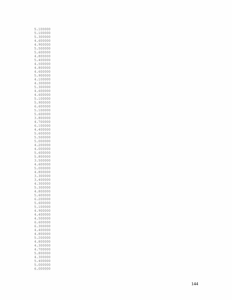
144
5.1000005.1000005.3000004.6000004.9000005.5000005.6000004.8000005.4000004.5000004.8000004.6000005.9000004.1000004.3000005.3000004.6000004.6000005.1000005.9000006.6000005.1000005.6000003.8000004.7000006.1000004.4000005.6000005.5000005.0000004.2000004.0000005.6000005.8000003.5000004.6000005.0000004.8000003.3000003.4000004.3000005.3000004.8000005.6000006.2000005.6000005.1000004.9000004.4000004.5000006.6000006.3000004.4000004.8000005.2000004.8000004.3000004.7000005.8000004.3000005.4000005.0000006.000000
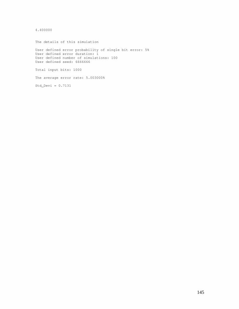
145
4.400000
The details of this simulation
User defined error probability of single bit error: 5%User defined error duration: 1User defined number of simulations: 100User defined seed: 6666666
Total input bits: 1000
The average error rate: 5.003000%
Std_Devi = 0.7131
146
Appendix E: C code for control file and comparator
E.1 Control File
//////////////////////////////////////////////////////////////////////////////// System Control//// Author: Xin Qu//// DATE: 5-18-00//// USAGE: filename//// DESCRIPTION: C control file///////////////////////////////////////////////////////////////////////////////
#include <iostream.h>#include <stdlib.h>#include <stdio.h>#include <time.h>#include <math.h>#include <string.h>#include <fstream.h>
int i=1, j=1, length, rand_seed, initial=0;char buf[100000];int x=0, y=0, z=0, ti, du, timepos, xpos=0, durpos;char tim[5];char dur[5];char seed[5];char filename[20];bool burstmode=false;
char int_to_char(int integer);int find_string(char *origin, char *target);
147
int main(int argc, char *argv[]){
FILE *testbench, *testbench1;// list all availablel test benches
cout<<endl<<"Please select the testbench from the listbelow..."<<endl<<endl;
system( "ls template*.vhd" );
// user input name of the testbenchcout<<endl<<"Please type the testbench to use in the
simulation:"<<endl<<endl;gets(filename);
// select test benchif( (testbench = fopen( filename, "r" )) == NULL ) {
cout << "Could not open testbench!" << endl;exit(EXIT_FAILURE);
}
//////////////////////////// select simulation mode
cout<<endl<<"Please choose simulation mode:"<<endl<<endl;cout<<"Type '1' for random error mode..."<<endl;cout<<"Type '2' for burst error mode..."<<endl<<endl;char a;scanf("%s", &a);
// random mode
if( a == '1' ) {cout<<endl<<endl<<"=============================="<<endl;cout<<"Random error mode is selected!"<<endl;cout<<"=============================="<<endl<<endl;cout<<"Compiling the VHDL Random channel model..."<<endl<<endl;system( "vhdlan chan.vhd" );
///////////////////////////// change ratio
cout << "Please input probability of single bit error: (0 -9999)*0.01%" <<endl;
cout << "Input 'r' for random ratio!" << endl;gets(tim);gets(tim);
////////////////////////////// change duration
cout << "Please input the duration of error: (from 0 - 10000)" <<endl;// cout << "Input 'r' for random duration!" << endl;
gets(dur);// gets(dur);///////////////////////////// input initial seed
cout << "Please input initial seed:" << endl;char init;scanf( "%d%c", &initial, &init );
}
// burst mode
else if( a == '2' ) {burstmode = true;cout<<endl<<endl<<"============================="<<endl;cout<<"Burst error mode is selected!"<<endl;
148
cout<<"============================="<<endl<<endl;cout<<"Compiling the VHDL Burst channel model..."<<endl<<endl;system( "vhdlan chan_burst.vhd" );
///////////////////////////// change ratio
cout << "please input the error occurs time: (from 0 - 9999)" <<endl;
gets(tim);gets(tim);
////////////////////////////// change duration
cout << "Please input the duration of error: (from 0 - 1000)" <<endl;// cout << "Input 'r' for random duration!" << endl;
gets(dur);///////////////////////////// input initial seed// char init='0';// scanf( "%d%c", &initial, &init );
}else {
cout<<endl<<endl<<"Invalid choice!!! Simulationterminated!!!"<<endl<<endl;
return EXIT_SUCCESS;}
length = fread( buf, sizeof( char ), 100000, testbench );// system( "vhdlsetup");
system( "rm record" );system( "rm record_channel" );system( "cp rec record" );system( "cp rec record_channel" );
/////////////////// change 'TIME'
if(tim[0]=='r') {tim[1]='1';tim[0]='-';
}char *s = "TIME <=";x = find_string(buf, s);timepos = x+8;while(tim[xpos]!=0){
buf[timepos+xpos]=tim[xpos];xpos++;
}for(x=xpos;x<5;x++)
buf[timepos+x]=' ';
/////////////////////// change 'DURATION'
if(dur[0]=='r') {dur[1]='1';dur[0]='-';
}
s = "ATION <=";y = find_string(buf, s);durpos = y+9;xpos=0;while(dur[xpos]!=0)
149
{buf[durpos+xpos]=dur[xpos];xpos++;
}for(x=xpos;x<5;x++)
buf[durpos+x]=' ';///////////////////////////// loop of simulation
if (burstmode==false) {cout << "Please input how many times the simulation will be executed?"
<<endl;char c;scanf( "%d%c", &i, &c );}
///////////////////////////// create random seed// srand( (unsigned)time( NULL ) );
srand( (unsigned)initial );for (j=0; j<i; j++) {
rand_seed = rand();
///////////////////////////// convert int to char
int y;for(int x=4; x>=0; x--){
y=rand_seed/(pow(10,x));seed[x]=int_to_char(y);rand_seed = rand_seed - (pow(10,x))*y;
}
///////////////////////////// change 'seed'
s = "seed <= ";z = find_string(buf, s);buf[z+8]=seed[0];buf[z+9]=seed[1];buf[z+10]=seed[2];buf[z+11]=seed[3];buf[z+12]=seed[4];
///////////////////////////// write to testbench
if( (testbench1 = fopen( "system_final_tb.vhd", "w" )) == NULL )cout << "Could not open testbench!" << endl;fwrite( buf, sizeof( char ), length, testbench1 );fclose( testbench1 );
cout<<"-------------------------------------------"<<endl;cout<<"Please wait... Compiling TestBench model..."<<endl;cout<<"-------------------------------------------"<<endl<<endl;system( "vhdlan -interp system_final_tb.vhd" );cout<<"-------------------------------------------"<<endl;cout<<"Simulation start, please wait..."<<endl;cout<<"-------------------------------------------"<<endl<<endl;system( "vhdlsim Parity_tb -i sim.txt" );system( "compare_channel channel.in channel.out" );system( "compare original.in final.out" );
} //end of simulation
/////////////////////////////////////////
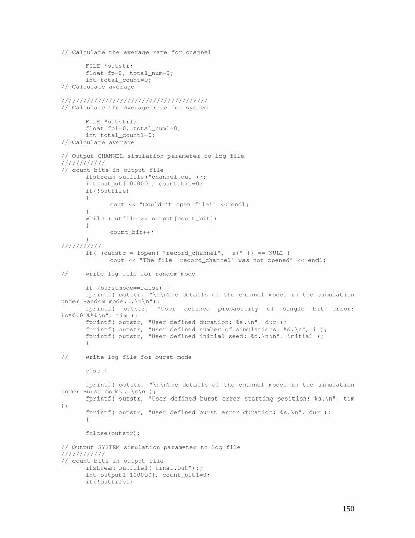
150
// Calculate the average rate for channel
FILE *outstr;float fp=0, total_num=0;int total_count=0;
// Calculate average
////////////////////////////////////////// Calculate the average rate for system
FILE *outstr1;float fp1=0, total_num1=0;int total_count1=0;
// Calculate average
// Output CHANNEL simulation parameter to log file////////////// count bits in output file
ifstream outfile("channel.out");;int output[100000], count_bit=0;if(!outfile){
cout << "Couldn't open file!" << endl;}while (outfile >> output[count_bit]){
count_bit++;}
///////////if( (outstr = fopen( "record_channel", "a+" )) == NULL )
cout << "The file 'record_channel' was not opened" << endl;
// write log file for random mode
if (burstmode==false) {fprintf( outstr, "\n\nThe details of the channel model in the simulation
under Random mode...\n\n");fprintf( outstr, "User defined probability of single bit error:
%s*0.01%%%\n", tim );fprintf( outstr, "User defined duration: %s.\n", dur );fprintf( outstr, "User defined number of simulations: %d.\n", i );fprintf( outstr, "User defined initial seed: %d.\n\n", initial );}
// write log file for burst mode
else {
fprintf( outstr, "\n\nThe details of the channel model in the simulationunder Burst mode...\n\n");
fprintf( outstr, "User defined burst error starting position: %s.\n", tim);
fprintf( outstr, "User defined burst error duration: %s.\n", dur );}
fclose(outstr);
// Output SYSTEM simulation parameter to log file////////////// count bits in output file
ifstream outfile1("final.out");;int output1[100000], count_bit1=0;if(!outfile1)
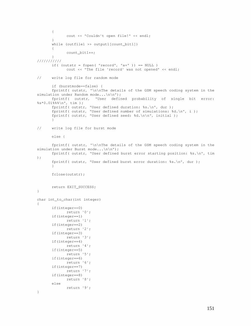
151
{cout << "Couldn't open file!" << endl;
}while (outfile1 >> output1[count_bit1]){
count_bit1++;}
///////////if( (outstr = fopen( "record", "a+" )) == NULL )
cout << "The file 'record' was not opened" << endl;
// write log file for random mode
if (burstmode==false) {fprintf( outstr, "\n\nThe details of the GSM speech coding system in the
simulation under Random mode...\n\n");fprintf( outstr, "User defined probability of single bit error:
%s*0.01%%%\n", tim );fprintf( outstr, "User defined duration: %s.\n", dur );fprintf( outstr, "User defined number of simulations: %d.\n", i );fprintf( outstr, "User defined seed: %d.\n\n", initial );}
// write log file for burst mode
else {
fprintf( outstr, "\n\nThe details of the GSM speech coding system in thesimulation under Burst mode...\n\n");
fprintf( outstr, "User defined burst error starting position: %s.\n", tim);
fprintf( outstr, "User defined burst error duration: %s.\n", dur );}
fclose(outstr);
return EXIT_SUCCESS;}
char int_to_char(int integer){
if(integer==0)return '0';
if(integer==1)return '1';
if(integer==2)return '2';
if(integer==3)return '3';
if(integer==4)return '4';
if(integer==5)return '5';
if(integer==6)return '6';
if(integer==7)return '7';
if(integer==8)return '8';
elsereturn '9';
}
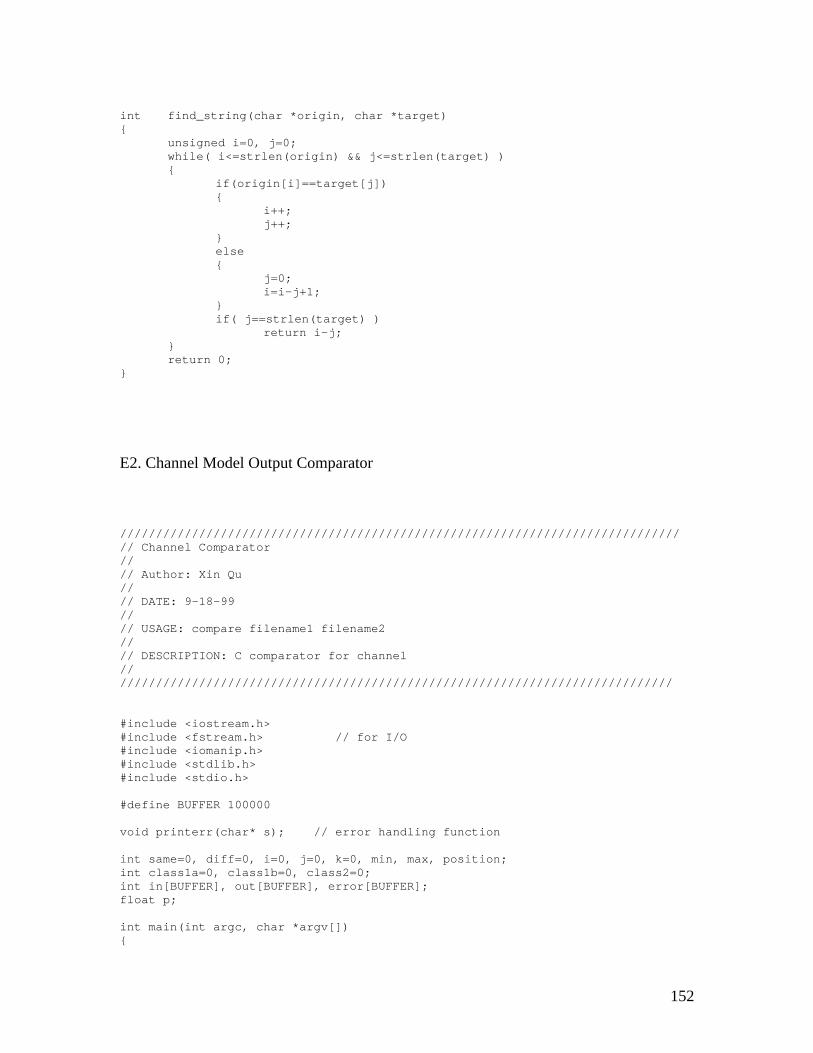
152
int find_string(char *origin, char *target){
unsigned i=0, j=0;while( i<=strlen(origin) && j<=strlen(target) ){
if(origin[i]==target[j]){
i++;j++;
}else{
j=0;i=i-j+1;
}if( j==strlen(target) )
return i-j;}return 0;
}
E2. Channel Model Output Comparator
//////////////////////////////////////////////////////////////////////////////// Channel Comparator//// Author: Xin Qu//// DATE: 9-18-99//// USAGE: compare filename1 filename2//// DESCRIPTION: C comparator for channel///////////////////////////////////////////////////////////////////////////////
#include <iostream.h>#include <fstream.h> // for I/O#include <iomanip.h>#include <stdlib.h>#include <stdio.h>
#define BUFFER 100000
void printerr(char* s); // error handling function
int same=0, diff=0, i=0, j=0, k=0, min, max, position;int class1a=0, class1b=0, class2=0;int in[BUFFER], out[BUFFER], error[BUFFER];float p;
int main(int argc, char *argv[]){
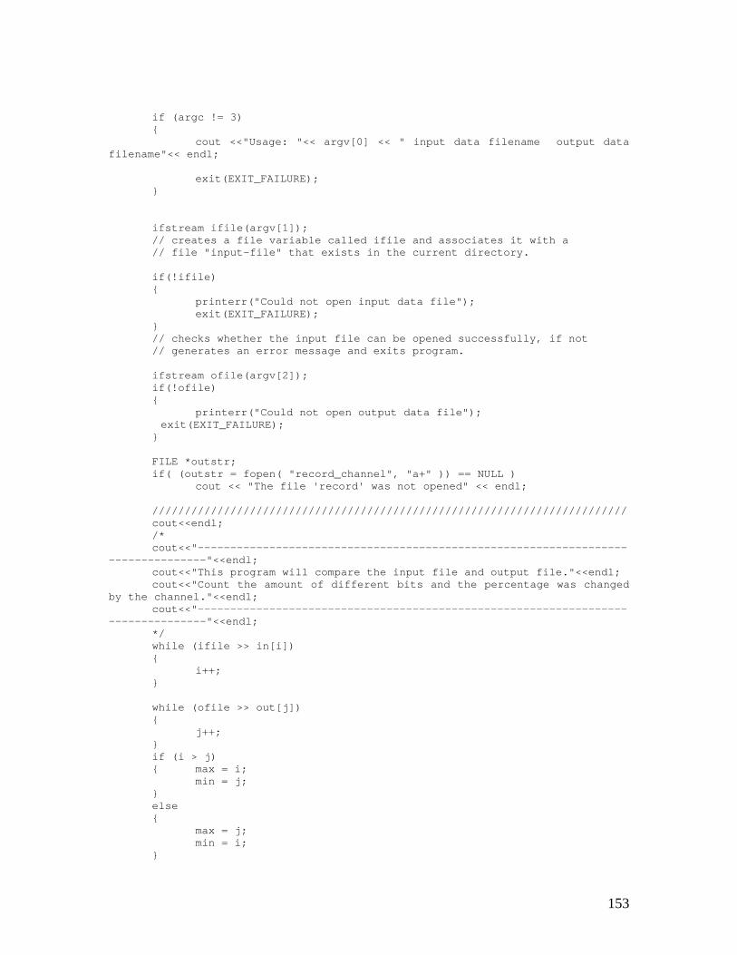
153
if (argc != 3){
cout <<"Usage: "<< argv[0] << " input data filename output datafilename"<< endl;
exit(EXIT_FAILURE);}
ifstream ifile(argv[1]);// creates a file variable called ifile and associates it with a// file "input-file" that exists in the current directory.
if(!ifile){
printerr("Could not open input data file");exit(EXIT_FAILURE);
}// checks whether the input file can be opened successfully, if not// generates an error message and exits program.
ifstream ofile(argv[2]);if(!ofile){
printerr("Could not open output data file");exit(EXIT_FAILURE);
}
FILE *outstr;if( (outstr = fopen( "record_channel", "a+" )) == NULL )
cout << "The file 'record' was not opened" << endl;
/////////////////////////////////////////////////////////////////////////cout<<endl;/*cout<<"------------------------------------------------------------------
---------------"<<endl;cout<<"This program will compare the input file and output file."<<endl;cout<<"Count the amount of different bits and the percentage was changed
by the channel."<<endl;cout<<"------------------------------------------------------------------
---------------"<<endl;*/while (ifile >> in[i]){
i++;}
while (ofile >> out[j]){
j++;}if (i > j){ max = i;
min = j;}else{
max = j;min = i;
}
154
// start comparing after 5 frames (data fill in the encoders, 3556clock cycles)
for (k=3556; k<min-3556; k++){
if (in[k] != out[k]) {error[diff]=k;diff++;}else
same++;}
if (diff!=0)p = (float) diff/(diff+same)*100;
elsep = 0;
// output resultsfprintf( outstr, "\nThere are totally %d bits in the input file.\n", i-
3556*2);fprintf( outstr, "There are totally %d bits in the output file.\n\n", j-
3556*2);
cout<<endl<<"Compare the input data and output data of channelmodel..."<<endl<<endl;
cout << "Compared totally " << i-3556*2 << " bits in the input file." <<endl;
cout << "Compared totally " << j-3556*2 << " bits in the output file."<<endl<<endl;
if (max != min) {cout<<"compared the first "<<min<<" bits!"<<endl;fprintf( outstr, "Compared the first %d bits!\n\n", min);
}cout << "Total different data is " << diff << " bits!" << endl<<endl;cout << "After pass the channel, the bit error rate was " <<
setprecision(6) << p << " %!" << endl << endl;fprintf( outstr, "Total different data is %d bits.\n\n", diff);
fprintf( outstr, "\nAfter pass the channel model, the bit error rate was%f%%%!\n\n", p);
fclose( outstr );
return EXIT_SUCCESS;}
void printerr(char *s){
cerr << s << endl;exit(EXIT_FAILURE);
}
E.3 System Output Comparator
155
//////////////////////////////////////////////////////////////////////////////// System Comparator//// Author: Xin Qu//// DATE: 9-18-99//// USAGE: compare filename1 filename2//// DESCRIPTION: C comparator for system output///////////////////////////////////////////////////////////////////////////////
#include <iostream.h>#include <fstream.h> // for I/O#include <iomanip.h>#include <stdlib.h>#include <stdio.h>
#define BUFFER 100000
void printerr(char* s); // error handling function
int same=0, diff=0, i=0, j=0, k=0, min, max, position;int class1a=0, class1b=0, class2=0;int in[BUFFER], out[BUFFER], error[BUFFER];float p;
int main(int argc, char *argv[]){
// bool Success;
if (argc != 3){
cout <<"Usage: "<< argv[0] << " input data filename output datafilename"<< endl;
exit(EXIT_FAILURE);}
ifstream ifile(argv[1]);// creates a file variable called ifile and associates it with a// file "input-file" that exists in the current directory.
if(!ifile){
printerr("Could not open input data file");exit(EXIT_FAILURE);
}// checks whether the input file can be opened successfully, if not// generates an error message and exits program.
ifstream ofile(argv[2]);if(!ofile){
printerr("Could not open output data file");exit(EXIT_FAILURE);
}
FILE *outstr;
156
if( (outstr = fopen( "record", "a+" )) == NULL )cout << "The file 'record' was not opened" << endl;
/////////////////////////////////////////////////////////////////////////cout<<endl;/*cout<<"------------------------------------------------------------------
---------------"<<endl;cout<<"This program will compare the input file and output file."<<endl;cout<<"Count the amount of different bits and the percentage was changed
by the channel."<<endl;cout<<"------------------------------------------------------------------
---------------"<<endl;*/while (ifile >> in[i]){
i++;}
while (ofile >> out[j]){
j++;}if (i > j){ max = i;
min = j;}else{
max = j;min = i;
}for (k=0; k<min; k++){
if (in[k] != out[k] && k%260!=259 && k%260!=255) {error[diff]=k;
// cout<<endl<<"k= "<<k<<endl;// cout<<endl<<"monitor= "<<k%260<<endl;
diff++;// if (diff>10)// break;
}else
same++;}
if (diff!=0)p = (float) diff/(diff+same)*100;
elsep = 0;
// fprintf( outstr, "The error possibility in this simulation: %f%%%\n\n", p);
fprintf( outstr, "\nThere are totally %d bits in the input file.\n", i);fprintf( outstr, "There are totally %d bits in the output file.\n\n", j);
cout << "Compare the input data and output data of GSM speech codingsystem..."<<endl<<endl;
cout << "There are totally " << i << " bits in the input file." << endl;cout << "There are totally " << j << " bits in the output file." << endl;if (max != min) {
cout<<"compared the first "<<min<<" bits!"<<endl;fprintf( outstr, "Compared the first %d bits!\n\n", min);
}
157
cout << "Total different data is " << diff << " bits!" << endl;cout << "After pass the GSM speech coding system, the bit error rate was
" << setprecision(6) << p << " %!" << endl << endl;fprintf( outstr, "Total different data is %d bits, the positions
are:\n\n", diff);
/*cout<<"Type '1' to see where are the errors, or any key else to
continue!"<<endl;char a;scanf( "%s", &a );if( a=='1' ) {*/// cout<<"Errors happened at: ";for( int b=0; b<diff; b++) {
position=error[b]+1;// cout<<"Errors happened at: "<<position<<" bit!"<<endl;
fprintf( outstr, "Uncorrectable error at bit position %d .\n",position);
if (position%260>=1 && position%260<=50)class1a++;
else if (position%260>=51 && position%260<=182)class1b++;
elseclass2++;
}
if (b!=0) {cout<<endl<<"The errors happened in Class 1a. are "<<class1a<<"
bits."<<endl;cout<<"The errors happened in Class 1b. are "<<class1b<<"
bits."<<endl;cout<<"The errors happened in Class 2. are "<<class2<<"
bits."<<endl<<endl;fprintf(outstr, "\nThere were %d uncorrectable bit errors in Class
1a.\n", class1a);fprintf(outstr, "There were %d uncorrectable bit errors in Class
1b.\n", class1b);fprintf(outstr, "There were %d uncorrectable bit errors in Class
2.\n", class2);}
fprintf( outstr, "\nAfter pass the GSM speech coding system, the biterror rate was %f%%%!\n\n", p);
fclose( outstr );
return EXIT_SUCCESS;}
void printerr(char *s){
cerr << s << endl;exit(EXIT_FAILURE);
}
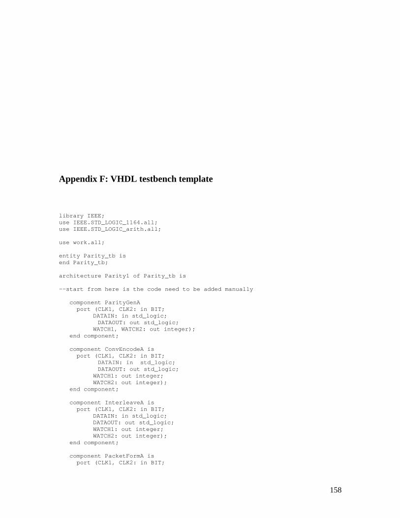
158
Appendix F: VHDL testbench template
library IEEE;use IEEE.STD_LOGIC_1164.all;use IEEE.STD_LOGIC_arith.all;
use work.all;
entity Parity_tb isend Parity_tb;
architecture Parity1 of Parity_tb is
--start from here is the code need to be added manually
component ParityGenAport (CLK1, CLK2: in BIT;
DATAIN: in std_logic;DATAOUT: out std_logic;
WATCH1, WATCH2: out integer);end component;
component ConvEncodeA isport (CLK1, CLK2: in BIT;
DATAIN: in std_logic;DATAOUT: out std_logic;
WATCH1: out integer;WATCH2: out integer);
end component;
component InterleaveA isport (CLK1, CLK2: in BIT;
DATAIN: in std_logic;DATAOUT: out std_logic;WATCH1: out integer;WATCH2: out integer);
end component;
component PacketFormA isport (CLK1, CLK2: in BIT;
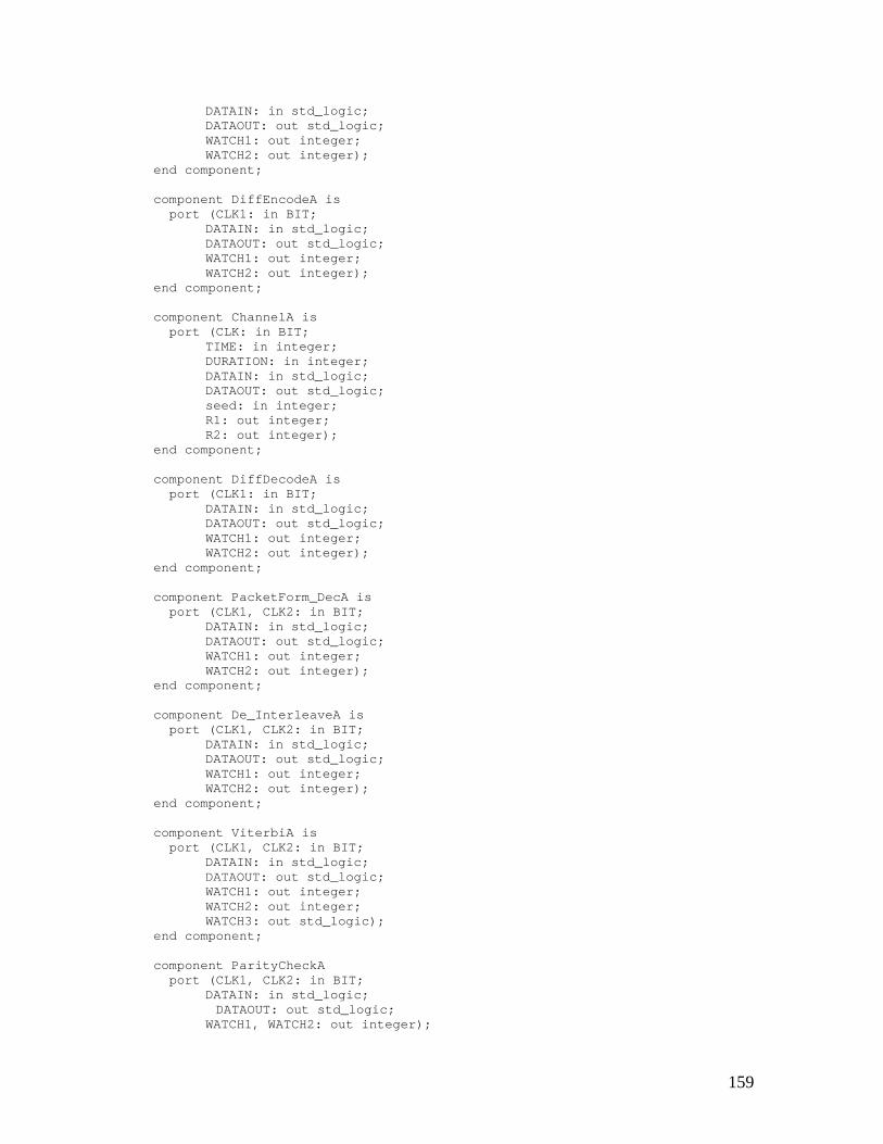
159
DATAIN: in std_logic;DATAOUT: out std_logic;WATCH1: out integer;WATCH2: out integer);
end component;
component DiffEncodeA isport (CLK1: in BIT;
DATAIN: in std_logic;DATAOUT: out std_logic;WATCH1: out integer;WATCH2: out integer);
end component;
component ChannelA isport (CLK: in BIT;
TIME: in integer;DURATION: in integer;DATAIN: in std_logic;DATAOUT: out std_logic;seed: in integer;R1: out integer;R2: out integer);
end component;
component DiffDecodeA isport (CLK1: in BIT;
DATAIN: in std_logic;DATAOUT: out std_logic;WATCH1: out integer;WATCH2: out integer);
end component;
component PacketForm_DecA isport (CLK1, CLK2: in BIT;
DATAIN: in std_logic;DATAOUT: out std_logic;WATCH1: out integer;WATCH2: out integer);
end component;
component De_InterleaveA isport (CLK1, CLK2: in BIT;
DATAIN: in std_logic;DATAOUT: out std_logic;WATCH1: out integer;WATCH2: out integer);
end component;
component ViterbiA isport (CLK1, CLK2: in BIT;
DATAIN: in std_logic;DATAOUT: out std_logic;WATCH1: out integer;WATCH2: out integer;WATCH3: out std_logic);
end component;
component ParityCheckAport (CLK1, CLK2: in BIT;
DATAIN: in std_logic;DATAOUT: out std_logic;
WATCH1, WATCH2: out integer);
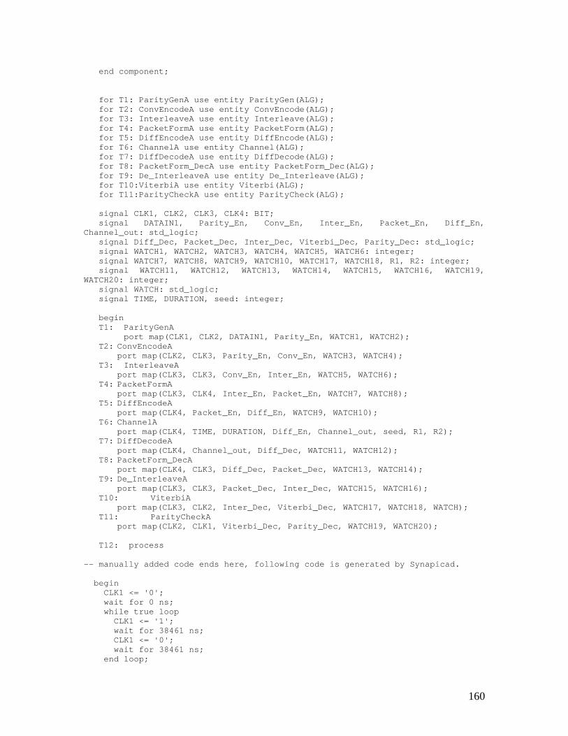
160
end component;
for T1: ParityGenA use entity ParityGen(ALG);for T2: ConvEncodeA use entity ConvEncode(ALG);for T3: InterleaveA use entity Interleave(ALG);for T4: PacketFormA use entity PacketForm(ALG);for T5: DiffEncodeA use entity DiffEncode(ALG);for T6: ChannelA use entity Channel(ALG);for T7: DiffDecodeA use entity DiffDecode(ALG);for T8: PacketForm_DecA use entity PacketForm_Dec(ALG);for T9: De_InterleaveA use entity De_Interleave(ALG);for T10:ViterbiA use entity Viterbi(ALG);for T11:ParityCheckA use entity ParityCheck(ALG);
signal CLK1, CLK2, CLK3, CLK4: BIT;signal DATAIN1, Parity_En, Conv_En, Inter_En, Packet_En, Diff_En,
Channel_out: std_logic;signal Diff_Dec, Packet_Dec, Inter_Dec, Viterbi_Dec, Parity_Dec: std_logic;signal WATCH1, WATCH2, WATCH3, WATCH4, WATCH5, WATCH6: integer;signal WATCH7, WATCH8, WATCH9, WATCH10, WATCH17, WATCH18, R1, R2: integer;signal WATCH11, WATCH12, WATCH13, WATCH14, WATCH15, WATCH16, WATCH19,
WATCH20: integer;signal WATCH: std_logic;signal TIME, DURATION, seed: integer;
beginT1: ParityGenA
port map(CLK1, CLK2, DATAIN1, Parity_En, WATCH1, WATCH2);T2: ConvEncodeA
port map(CLK2, CLK3, Parity_En, Conv_En, WATCH3, WATCH4);T3: InterleaveA
port map(CLK3, CLK3, Conv_En, Inter_En, WATCH5, WATCH6);T4: PacketFormA
port map(CLK3, CLK4, Inter_En, Packet_En, WATCH7, WATCH8);T5: DiffEncodeA
port map(CLK4, Packet_En, Diff_En, WATCH9, WATCH10);T6: ChannelA
port map(CLK4, TIME, DURATION, Diff_En, Channel_out, seed, R1, R2);T7: DiffDecodeA
port map(CLK4, Channel_out, Diff_Dec, WATCH11, WATCH12);T8: PacketForm_DecA
port map(CLK4, CLK3, Diff_Dec, Packet_Dec, WATCH13, WATCH14);T9: De_InterleaveA
port map(CLK3, CLK3, Packet_Dec, Inter_Dec, WATCH15, WATCH16);T10: ViterbiA
port map(CLK3, CLK2, Inter_Dec, Viterbi_Dec, WATCH17, WATCH18, WATCH);T11: ParityCheckA
port map(CLK2, CLK1, Viterbi_Dec, Parity_Dec, WATCH19, WATCH20);
T12: process
-- manually added code ends here, following code is generated by Synapicad.
beginCLK1 <= '0';wait for 0 ns;while true loop
CLK1 <= '1';wait for 38461 ns;CLK1 <= '0';wait for 38461 ns;
end loop;
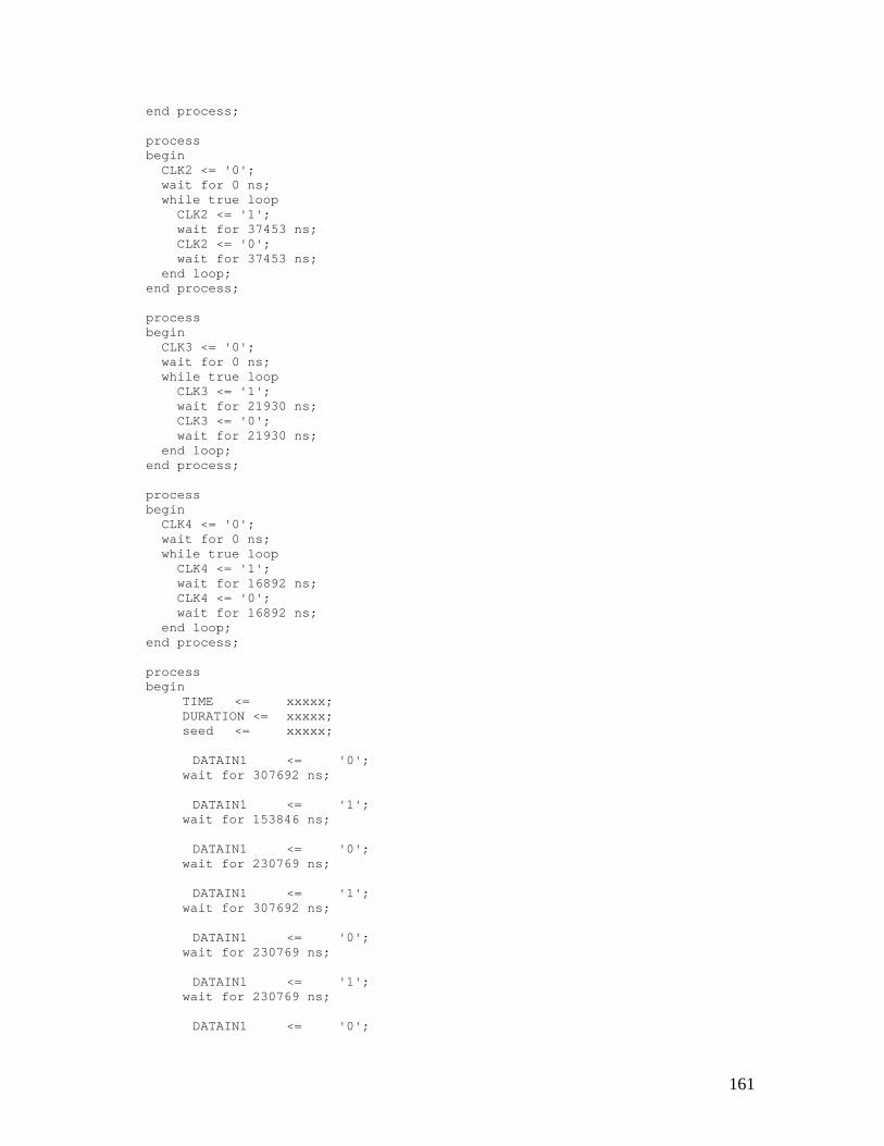
161
end process;
processbegin
CLK2 <= '0';wait for 0 ns;while true loop
CLK2 <= '1';wait for 37453 ns;CLK2 <= '0';wait for 37453 ns;
end loop;end process;
processbegin
CLK3 <= '0';wait for 0 ns;while true loop
CLK3 <= '1';wait for 21930 ns;CLK3 <= '0';wait for 21930 ns;
end loop;end process;
processbegin
CLK4 <= '0';wait for 0 ns;while true loop
CLK4 <= '1';wait for 16892 ns;CLK4 <= '0';wait for 16892 ns;
end loop;end process;
processbegin
TIME <= xxxxx;DURATION <= xxxxx;seed <= xxxxx;
DATAIN1 <= '0';wait for 307692 ns;
DATAIN1 <= '1';wait for 153846 ns;
DATAIN1 <= '0';wait for 230769 ns;
DATAIN1 <= '1';wait for 307692 ns;
DATAIN1 <= '0';wait for 230769 ns;
DATAIN1 <= '1';wait for 230769 ns;
DATAIN1 <= '0';
162
wait for 153846 ns;...
.
.
.DATAIN1 <= '0';
wait for 153846 ns;
DATAIN1 <= '1';wait for 230769 ns;
DATAIN1 <= '0';wait for 153846 ns;
DATAIN1 <= '1';wait for 76923 ns;...wait;
end process;
end Parity1;
163
Vita
Xin Qu was born on July 29, 1976 in Beijing, China. He graduated with a Bachelor of
Engineering degree in Electrical Engineering from Beijing Institute of Technology in
May 1998. He attended graduate school at Virginia Polytechnic Institute and State
University and received a Master of Science degree in Computer Engineering in
December 2000.