Embed Size (px)
Citation preview
1
System Specification Document (SSD v1)
Version 1.0
28 June 2013
Prepared by
TU Wien, VUA, GeoVille, ETH Zürich, AWST, FMI, UCC and NILU

System Specification Document Version 1.0
Date 28 June 2013
i
This document forms deliverable D5.2 and was compiled for the ESA Climate Change
Initiative Phase 1 Soil Moisture Project (ESRIN Contract No. 4000104814/11/I-NB). For more
information on the CCI programme of the European Space Agency (ESA) see
http://www.esa-cci.org/.
Number of pages: 64
Authors: M. Ertl, A. Boresch
Circulation (internal): Project consortium and science partners
External: ESA
Issue Date Details Editor
0.1 2012-11-29 Document template with annotated TOC. A. Boresch
0.2 2013-06-14 Added introduction and references (sections 1 and 2). Included descriptions of architectural factors and design decisions from architectural design workshops (sections 3 and 4).
M. Ertl , A. Boresch
0.3 2013-06-18 Peer review of sections 1-4. A. Boresch
0.4 2013-06-24 Added specification of the System’s architecture in terms of architectural views (section 5, views 1-5 and 7).
M. Ertl
0.5 2013-06-24 Addressed comments received from TUW. M. Ertl
0.6 2013-06-25 Peer review of section 5. A. Boresch
0.7 2013-06-27 Addressed comments received from peer review and from EP4SM project.
J. Strasser, M. Ertl
1.0 2013-06-28 Finalization for delivery of version 1. M. Ertl, A. Boresch
For any clarifications please contact Martin Ertl ([email protected]).

System Specification Document Version 1.0
Date 28 June 2013
ii
Table of Contents
1 INTRODUCTION ....................................................................................................................................... 1
1.1 PURPOSE AND SCOPE OF DOCUMENT ................................................................................................................ 1
1.2 DOCUMENT OVERVIEW ................................................................................................................................... 1
1.3 TARGET AUDIENCE ......................................................................................................................................... 2
1.4 TERMINOLOGY USED IN THIS DOCUMENT ........................................................................................................... 2
2 REFERENCES ............................................................................................................................................ 5
2.1 APPLICABLE DOCUMENTS ................................................................................................................................ 5
2.2 REFERENCE DOCUMENTS................................................................................................................................. 5
3 ARCHITECTURAL FACTORS ...................................................................................................................... 8
3.1 SYSTEM PURPOSE AND INTENDED USE ............................................................................................................... 8
3.2 OVERVIEW OF SYSTEM CONTEXT..................................................................................................................... 10
3.3 MAIN EXTERNAL INTERFACES ......................................................................................................................... 12
3.4 INSTALLATION SITE CHARACTERISTICS .............................................................................................................. 12
3.5 DESIGN CONSTRAINTS .................................................................................................................................. 13
3.6 CANDIDATE SYSTEM ARCHITECTURES ............................................................................................................... 16
3.7 DECISION METHODS..................................................................................................................................... 18
4 DOCUMENTATION OF ARCHITECTURAL DESIGN DECISIONS .................................................................. 20
4.1 GENERAL CONSIDERATIONS ........................................................................................................................... 20
4.2 CCI COMMON ELEMENTS AND COLLABORATION ................................................................................................ 26
4.3 DATA PROCESSING SOFTWARE ....................................................................................................................... 29
5 SYSTEM ARCHITECTURE ........................................................................................................................ 33
5.1 FUNCTIONAL VIEW ....................................................................................................................................... 34
5.2 ORGANIZATION VIEW ................................................................................................................................... 36
5.3 SOFTWARE VIEW ......................................................................................................................................... 37
5.3.1 Application Software ..................................................................................................................... 38
5.3.2 Platform Software ......................................................................................................................... 39
5.3.3 Platform Composition ................................................................................................................... 41
5.4 PROCESS VIEW ............................................................................................................................................ 45
5.4.1 Data Acquisition Process ............................................................................................................... 45
5.4.2 ECV Production Process ................................................................................................................. 47
5.4.3 Software Change Process .............................................................................................................. 49
5.4.4 ECV Change Process ...................................................................................................................... 52
5.5 USE-CASE VIEW .......................................................................................................................................... 52
5.6 INFORMATION VIEW ..................................................................................................................................... 55
5.7 INFRASTRUCTURE VIEW ................................................................................................................................. 55
5.8 LIFE CYCLE SUSTAINMENT ACTIVITIES .............................................................................................................. 57
6 TRACEABILITY MATRIX .......................................................................................................................... 57

System Specification Document Version 1.0
Date 28 June 2013
iii
List of Figures
FIGURE 1: SYSTEM FUNCTIONS HIERARCHY ..................................................................................................................... 34
FIGURE 2: ORGANIZATIONAL CHART OF THE SOIL MOISTURE ECVPS ................................................................................... 36
FIGURE 3: SOFTWARE CONFIGURATION HIERARCHY FOR APPLICATION SOFTWARE .................................................................. 38
FIGURE 4: SOFTWARE CONFIGURATION HIERARCHY FOR PLATFORM SERVICES ....................................................................... 39
FIGURE 5: SOFTWARE CONFIGURATION HIERARCHY FOR GEO LIBRARIES ............................................................................... 41
FIGURE 6: PLATFORM COMPOSITION BY ENVIRONMENTS (ENVS) AND VIRTUAL MACHINES (VMS) ........................................... 42
FIGURE 7: ACTIVITY FLOW FOR ACQUISITION OF L2 DATA AND ANCILLARY DATA .................................................................... 46
FIGURE 8: ACTIVITY FLOW FOR THE PRODUCTION OF ECV DATA PRODUCTS .......................................................................... 48
FIGURE 9: ACTIVITY FLOW FOR RESOLUTION OF SOFTWARE ISSUES, SOFTWARE DEVELOPMENT AND TESTING ................................ 50
FIGURE 10: CLOUD INFRASTRUCTURE FOR DEPLOYMENT OF THE SOIL MOISTURE ECVPS ......................................................... 56
List of Tables
TABLE 1: TECHNICAL TERMS........................................................................................................................................... 2
TABLE 2: MISSION OF THE SOIL MOISTURE ECV PRODUCTION SYSTEM (SM ECVPS) ............................................................... 8
TABLE 3: OBJECTIVES OF THE SOIL MOISTURE ECVPS ......................................................................................................... 8
TABLE 4: LIST OF ARCHITECTURAL FACTORS FOR CONSIDERATION IN THE ARCHITECTURAL ANALYSIS ............................................ 13
TABLE 5: LIST OF TRADE-OFF ISSUES AND CANDIDATE SOLUTIONS ....................................................................................... 17
TABLE 6: ARCHITECTURAL DESIGN TEAM ........................................................................................................................ 19
TABLE 7: TEMPLATE FOR TECHNICAL MEMOS (TMS) ........................................................................................................ 20
TABLE 8: (TM-001) SYSTEM SPECIFICATION APPROACH ................................................................................................... 20
TABLE 9: (TM-002) FUNCTIONAL SCOPE ....................................................................................................................... 21
TABLE 10: (TM-003) REQUIREMENTS MATURITY STATUS ................................................................................................ 22
TABLE 11: (TM-004) DEVELOPMENT CAPABILITY ............................................................................................................ 23
TABLE 12: (TM-005) ECV DEPENDENCY ....................................................................................................................... 24
TABLE 13: (TM-006) STANDARDIZATION ...................................................................................................................... 25
TABLE 14: (TM-007) SUSTAINMENT ............................................................................................................................ 25
TABLE 15: (TM-008) CCI WEB PORTAL ........................................................................................................................ 26
TABLE 16: (TM-009) PROCESSING ENVIRONMENT .......................................................................................................... 27
TABLE 17: (TM-010) L1 DATA ARCHIVE ....................................................................................................................... 28
TABLE 18: (TM-011) VERSION CONTROL ...................................................................................................................... 28
TABLE 19: (TM-012) ECV PROCESSOR ARCHITECTURE .................................................................................................... 29
TABLE 20: (TM-013) ECV PROCESSOR PROGRAMMING LANGUAGE ................................................................................... 30
TABLE 21: (TM-014) ECV PROCESSOR PERFORMANCE .................................................................................................... 32
TABLE 22: MAIN USE CASES OF THE SOIL MOISTURE ECVPS ............................................................................................. 52
TABLE 23: TEMPLATE FOR USE CASES (UCS) ................................................................................................................... 52
TABLE 24: (UC-001) DOWNLOAD ECV DATA PRODUCT ................................................................................................... 53
TABLE 25: (UC-002) VIEW ECV DATA PRODUCT ............................................................................................................ 53
TABLE 26: (UC-003) COMPARE ECV DATA PRODUCTS .................................................................................................... 54
System Specification Document Version 1.0
Date 28 June 2013
iv
List of Acronyms
AWST Angewandte Wissenschaft Software und Technologie GmbH
CCB Configuration Control Board
CCI Climate Change Initiative
CDR Climate Data Record
CEOS Committee on Earth Observation Satellites
CF Climate and Forecasting
CMUG Climate Modelling User Group
CNES Centre National d'Etudes Spatiales
CPU Central Processing Unit
DMZ Demilitarized Zone
DVCS Distributed Version Control System
DVL Development
ECMWF European Centre for Medium Range Weather Forecasting
ECV Essential Climate Variable
ECVPS ECV Production System
ENV Environment
ESA European Space Agency
FAQ Frequently Asked Questions
FCDR Fundamental Climate Data Record
FTE Full-Time Equivalent
FTP File Transfer Protocol
GbE Gigabit Ethernet
GCOS Global Climate Observing System
GEO Group on Earth Observation
GEWEX Global Energy and Water Cycle Experiment
GTOS Global Terrestrial Observing System
IaaS Infrastructure as a Service
IDL Interactive Data Language
IGWCO Integrated Global Water Cycle Observations

System Specification Document Version 1.0
Date 28 June 2013
v
ISMWG International Soil Moisture Working Group
ISO International Organization for Standardization
IT Information Technology
L1b Level 1b
L2 Level 2
L3s Level 3 super-collated
LAN Local Area Network
LPRM Land Parameter Retrieval Model
LVP GEO Land Product Validation
MTBF Mean Time Between Failures
NASA National Aeronautics and Space Administration
OPS Operations
OS Operating System
PaaS Platform as a Service
PC Personal Computer
PCB Product Control Board
PECVPS Prototype ECV Production System
PSD Product Specification Document
RAM Random Access Memory
SaaS Software as a Service
SAD Software Architecture Document
SM Soil Moisture
SM ECVPS Soil Moisture ECV Production System
SM PECVPS Soil Moisture Prototype ECV Production System
SMAP Soil Moisture Active Passive
SMOS Soil Moisture and Ocean Salinity
SRD System Requirements Document
SSD System Specification Document
TBD To Be Determined
TCDR Thematic Climate Data Record
TM Technical Memo

System Specification Document Version 1.0
Date 28 June 2013
vi
TOPC Terrestrial Observation Panel on Climate
TST Test
TUW TU Wien
UP Unified Process
URD User Requirements Document
VCS Version Control System
VM Virtual Machine
VOD Vegetation Optical Depth
VPN Virtual Private Network
VUA Vrije University of Amsterdam
WARP soil WAter Retrieval Package
WCRP World Climate Research Programme
WGS World Geodetic System
WOAP WCRP Observations and Assimilation Panel

System Specification Document Version 1.0
Date 28 June 2013
1
1 Introduction
1.1 Purpose and Scope of Document
This System Specification Document (SSD) specifies the architecture of the Soil Moisture
(SM) Essential Climate Variable (ECV) Production System (conveniently abbreviated “SM
ECVPS” and generally termed “the System” in this document). While the SM ECVPS will be
developed and implemented in the ESA Climate Change Initiative (CCI) Phase 2, the SSD is a
deliverable under the ESA CCI Phase 1 Soil Moisture project [PROP1].
The document fulfills the following purposes:
The SSD describes the operational context and main interfaces of the SM ECVPS, and
specifies the System’s architecture in terms of complementary architectural views on
the basis of system and user requirements, as specified in [SRD] and [URD].
The SSD documents the architectural factors (requirements, constraints and
assumptions) that influenced architectural design decisions. It provides records of the
trade-off analyses and the rationales of design decisions.
The SSD forms the main technical input to the System construction and Subsystem
development to be performed under the planned ESA CCI Phase 2 Soil Moisture
project, and provides guidance for the project setup and planning.
Scope considerations:
The SSD does not include a work breakdown, or an implementation plan or funding
plan for the System’s development, construction and operations. These are expected
to be covered elsewhere.
The document does not repeat the technical specifications of Soil Moisture ECV
Products and the ECV Processor Subsystem, as those are specified in [PSD], [DPM]
and [IODD].
1.2 Document Overview
The document contains six major sections:
Section 1: Introduction to the document (this section).
Section 2: Listing of applicable and referenced documents.
Section 3: Descriptions of purpose and intended use of the System, its operational
context and the Architectural Factors (requirements, constraints and assumptions)
that influenced architectural design decisions.

System Specification Document Version 1.0
Date 28 June 2013
2
Section 4: Records of the architectural trade-off analyses and design decisions in the
form of Technical Memos (TMs).
Section 5: Specification of the System’s architecture in terms of complementary
architectural views.
Section 6: Tracing of requirements to System architecture elements.
1.3 Target Audience
The prime audience are the CCI management team and the Soil Moisture CCI Phase 2 project
team.
Within the systems engineering process of the Soil Moisture CCI project, it will form the
basis for the construction of the SM ECVPS and the development of its Subsystems under CCI
Phase 2.
During these phases and beyond the SSD will form a lasting reference of the original
architectural design, and will help future system maintainers and developers to understand
the systems origins and the rationale behind the design decisions made.
Another target audience are the system engineering teams for ECV Production Systems of
other CCI projects, who may learn about differences and similarities between the ECV
Production Systems in order to judge the feasibility of designing and implementing common
components that could be used by more than one ECVPS.
1.4 Terminology Used in this Document
Terms that are used with a specific technical meaning in this document are defined in
Table 1.
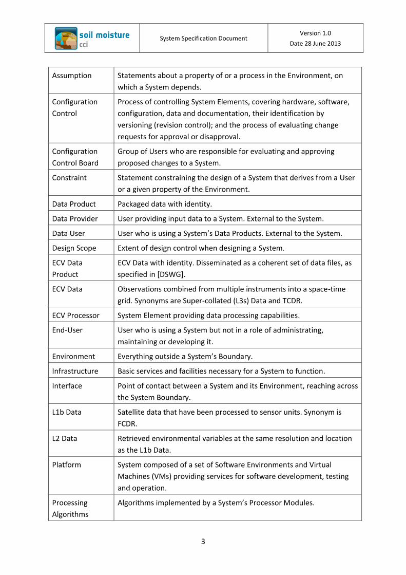
Table 1: Technical Terms
Application
Software
Subset of a vertically broadly scoped Information System: combination
of all software components required to fulfill the System’s
responsibilities specific to its business domain.
Architectural
Factor
Requirements, constraints or assumptions that have an impact on the
architectural design.
Architectural
View
Reduced design description of a System’s architecture that puts the
focus on a specific aspect like the System’s static or logical structure, its
main control flows, or its essential components, etc; the complete
architectural design is then obtained by mentally matching concurrent
Architectural Views together.
System Specification Document Version 1.0
Date 28 June 2013
3
Assumption Statements about a property of or a process in the Environment, on
which a System depends.
Configuration
Control
Process of controlling System Elements, covering hardware, software,
configuration, data and documentation, their identification by
versioning (revision control); and the process of evaluating change
requests for approval or disapproval.
Configuration
Control Board
Group of Users who are responsible for evaluating and approving
proposed changes to a System.
Constraint Statement constraining the design of a System that derives from a User
or a given property of the Environment.
Data Product Packaged data with identity.
Data Provider User providing input data to a System. External to the System.
Data User User who is using a System’s Data Products. External to the System.
Design Scope Extent of design control when designing a System.
ECV Data
Product
ECV Data with identity. Disseminated as a coherent set of data files, as
specified in [DSWG].
ECV Data Observations combined from multiple instruments into a space-time
grid. Synonyms are Super-collated (L3s) Data and TCDR.
ECV Processor System Element providing data processing capabilities.
End-User User who is using a System but not in a role of administrating,
maintaining or developing it.
Environment Everything outside a System’s Boundary.
Infrastructure Basic services and facilities necessary for a System to function.
Interface Point of contact between a System and its Environment, reaching across
the System Boundary.
L1b Data Satellite data that have been processed to sensor units. Synonym is
FCDR.
L2 Data Retrieved environmental variables at the same resolution and location
as the L1b Data.
Platform System composed of a set of Software Environments and Virtual
Machines (VMs) providing services for software development, testing
and operation.
Processing
Algorithms
Algorithms implemented by a System’s Processor Modules.

System Specification Document Version 1.0
Date 28 June 2013
4
Product Control
Board
Group of Users who are responsible for evaluating and approving
proposed changes to Data Products.
Product
Specification
Specification of a Data Product forming the basis for production and use
of the Data Product.
Regulatory
Organizations
Elements of a System’s Environment with controlling or enabling impact
on the System.
Requirement Statement constraining the design of a System that derives from an
expressed need of a User of the System.
Resampling Interpolation and extrapolation of data points as needed to pass data
sampled on a specific temporal and spatial grid to another one.
Rescaling Normalization technique employed in processing of Soil Moisture data.
Scientific
Methods
Methods describing the science aspects of Processing Algorithms.
Software
Component
System Element constituted by computer software.
Software
Configuration
Hierarchy
Hierarchical Configuration of Software Components.
Software
Environment
Environment for developing, testing or running software applications.
Subsystem System Element at the first decomposition level of a System.
System Set of interacting or interdependent components to be specified,
designed and constructed, separated from its Environment by a
boundary (the “System Boundary”).
System Boundary Boundary between a System and the rest of the world (its
Environment).
System Element Part of a System at any decomposition level.
System Function Range of activities to be performed by a System; a System Function may
be accomplished by one or more System Elements comprised of
personnel, hardware, software, data and facilities; System Functions are
identified by functional analysis, and the whole set of System Functions
must match up to the System’s purpose.
System Team System Element constituted by the group of Users who operate,
maintain or develop the System.

System Specification Document Version 1.0
Date 28 June 2013
5
2 References
2.1 Applicable Documents
The documents outlined here detail the scope and focus for the work that is reported in this
document.
[CNTR1] Phase 1 of the ESA Climate Change Initiative Soil-Moisture-cci. ESRIN Contract
No: 4000104814/11/I-NB.
[KO1] Phase 1 of the ESA Climate Change Initiative Soil-Moisture-cci. Kick-Off Meeting,
Minutes of Meeting, 18.01.2012, ESA_CCI_SoilMoisture_KO_17_180112.doc
[NEG1] Phase 1 of the ESA Climate Change Initiative Soil-Moisture-cci. Contract
Negotiation and Clarification Meeting, Minutes of Meeting, 21.10.2011,
ESA_CCI_SoilMoisture_MINUTES_contract_meeting_21102011.doc
[PROP1] Proposal (Parts 1-5) in response to ESA Climate Change Initiative Phase 1
ESRIN/AO/1-6782/11/I-NB, Vienna University of Technology.
[SOW1] ESA Climate Change Initiative Phase 1, Statement of Work for Soil Moisture and
Ice Sheets, European Space Agency, EOEP-STRI-EOPS-SW-11-0001.
[SOW1-SM] ESA Climate Change Initiative Phase 1, Statement of Work for Soil Moisture
and Ice Sheets, Annex L: Soil Moisture ECV (Soil_Moisture_cci), European Space
Agency, annex to EOEP-STRI-EOPS-SW-11-0001.
2.2 Reference Documents
This section provides a list of reference documents upon which this document is either
based, or to which this document refers.
[Ahson11] Cloud Computing and Software Services: Theory and Techniques, editors
Syed A. Ahson and Mohammad Ilyas, CRC Press, 2011.
[ATBD] Algorithm Theoretical Baseline Document, Version 1, 14 February 2013, ESA
Climate Change Initiative Phase 1 Soil Moisture Project, http://www.esa-
soilmoisture-cci.org/node/119, 20130214_CCI_Soil_Moisture_ATBD1.v1.0.pdf
and 20130214_CCI_Soil_Moisture_ATBD1_Annex1.v1.0.pdf
[CCI-SRD] ESA CCI-wide System Requirements Document, at the time of writing in
production by ESA and not available to the authors; as substitute referring to
collection of loose papers distributed to the SEWG during April to September
2012: (FR) CCI Functional Requirements etc v2.docx, (IR) Interface

System Specification Document Version 1.0
Date 28 June 2013
6
Requirements_0_3.docx, (RR) Reliability Requirements_0_2.doc, (N) SEWG
04_09_12 notes.docx
[CECR] Comprehensive Error Characterisation Report, Version 0.7, 21 May 2012, ESA
Climate Change Initiative Phase 1 Soil Moisture Project, http://www.esa-
soilmoisture-cci.org/node/119,
20120521_CCI_Soil_Moisture_D1.2.1_CECR_v.0.7.pdf
[Colloc1] ESA CCI First Collocation. Presentation: System Engineering Recommendations
from Drafting Team, SystemEngineeringRecom.pdf.
[Colloc2] ESA CCI Second Collocation Report, CCI-PRGM-EOPS-TN-11-0029, Issue 1,
Revision 0, Pascal Lecomte and Cat Downy, February 7th, 2012,
CCISecondCollocationReport.pdf
[DARD] Data Access Requirements Document, Version 1.2, 13 April 2012, ESA Climate
Change Initiative Phase 1 Soil Moisture Project, http://www.esa-soilmoisture-
cci.org/node/119, 20120413_CCI_Soil_Moisture_D1.3_DARD_v.1.2.pdf
[DSWG] ESA, Guidelines for Data Producers – Climate Change Initiative Phase 1, CCI-
PRGM-EOPS-TN-11-0003, Issue 3, Revision 1, Victoria Bennett, 20/07/2012,
CCI_Data_Standards_Guidelines_v5_July2012.pdf
[DPM] Detailed Processing Model, Version 1.0, 28 August 2012, ESA Climate Change
Initiative Phase 1 Soil Moisture Project, http://www.esa-soilmoisture-
cci.org/node/119, 20121126_CCI_Soil_Moisture_D2.7_DPM_v.1.0.pdf
[ECSS-E-ST-40C] European Cooperation for Space Standardization (ECSS), Space
Engineering Software, ECSS-E-ST-40C, ECSS Secretariat, ESA-ESTEC, Requirements
& Standards Division, Noordwijk, The Netherlands, 6 March 2009.
[EP4SM-SAD] Exploitation Platform Demonstrator for Soil Moisture (EP4SM), System
Architecture Document, AWST-TR 13/04, ESA-ESRIN, Version 1.0, April 8, 2013.
[IODD] Input/Output Data Definition Document, Version 1.0, 21 December 2012, ESA
Climate Change Initiative Phase 1 Soil Moisture Project, http://www.esa-
soilmoisture-cci.org/node/119,
20121221_CCI_Soil_Moisture_D2.8_IODD_v1.0.pdf
[Kruchten95] Architectural Blueprints – The 4+1 View Model of Software Architecture,
Philippe Kruchten, IEEE Software 12 (6), pp. 42-50, November 1995.
[Larman02], Applying UML and Patterns – An Introduction to Object-Oriented Analysis
and Design and the Unified Process, Craig Larman, PH PTR, 2nd Ed., 2002.

System Specification Document Version 1.0
Date 28 June 2013
7
[NETCDF] NetCDF Climate and Forecast (CF) Metadata Conventions: Version 1.6, 5
December, 2011, Brian Eaton, Jonathan Gregory, Bob Drach, Karl Taylor, and
Steve Hankin.
[PSS-05-0] ESA PSS-05-0 Software Engineering Standards, Issue 2, ESA Board for
Software Standardisation and Control (BSSC), ESA-ESTEC, February 1991.
[PSS-05-03] ESA PSS-05-03 Guide to the software requirements definition phase, Issue
1, Revision 1, ESA Board for Software Standardisation and Control (BSSC), ESA-
ESTEC, March 1995.
[PSD] Product Specification Document, Version 1.0, 26 November 2012, ESA Climate
Change Initiative Phase 1 Soil Moisture Project, http://www.esa-soilmoisture-
cci.org/node/119, 20121126_ECV_SM_Product_Specification_Document_1.0.pdf
[PVP] Product Validation Plan, Version 1.0, 31 May 2012, ESA Climate Change Initiative
Phase 1 Soil Moisture Project, http://www.esa-soilmoisture-cci.org/node/119,
20120531_CCI_Soil_Moisture_D2.1_PVP_v.1.0.pdf
[RM-ODP98] Information technology – Open Distributed Processing: Reference Model –
Part 1: Overview, ISO/IEC 10746-1:1998, International Organization for
Standardization, Geneva, Switzerland, 1998.
[Shames06]. Toward a Framework for Modeling Space Systems Architectures, Peter
Shames and Joseph Skipper, NASA, JPL, 2006.
[SRD] System Requirements Document, Version 1.0, 21 December 2012, ESA Climate
Change Initiative Phase 1 Soil Moisture Project, http://www.esa-soilmoisture-
cci.org/node/119, 20121221_CCI_Soil_Moisture_D5.1_SRD.pdf
[URD] User Requirements Document, Version 0.6, 30 November 2012, ESA Climate
Change Initiative Phase 1 Soil Moisture Project, CCI_Soil_Moisture_D1.1_URD.pdf

System Specification Document Version 1.0
Date 28 June 2013
8
3 Architectural Factors
3.1 System Purpose and Intended Use
The Soil Moisture ECV Production System (SM ECVPS, termed “the System” in this
document) serves a single purpose expressed by the statement of Table 2, which we adopt
as the System’s Mission.
Table 2: Mission of the Soil Moisture ECV Production System (SM ECVPS)
Mission Statement
Produce the most complete and consistent within scientific and observational limits, global,
long-time continuous, multi-sensor, error characterized and verified Soil Moisture Data
Products, from satellite and in-situ measurements, for use in Climate Research and
Modeling.
Note: In the context of Soil Moisture “global” means covering all Earth land surfaces, and “long-time continuous” means beginning with the first available satellite measurements in 1978, since then passing from one satellite generation with radiometer (passive) or scatterometer (active) sensors to the next and aiming to extend to future satellite generations.
This mission statement was inspired from [SOW1], CR-2. On its basis we develop a short list
of prime functions complementing the Mission Statement and necessary for the System to
provide in order to achieve its Mission. These functions are stated in Table 3 and constitute
the System Objectives.
Table 3: Objectives of the Soil Moisture ECVPS
OBJ-# System Objective
OBJ-01 Produce Soil Moisture ECV Data Products that meet the requirements as specified in [URD], “Key requirements for an ECV soil moisture data set”.
OBJ-02 Continuously develop and improve ECV Data Products, Scientific Methods and Processing Algorithms, a) to update to changing and steadily becoming more demanding requirements by data users, and b) to extend the ECV Data Products by the data from planned future satellite missions.
OBJ-03 Acquire input data of sufficient quality for the production and development of ECV Data Products.
OBJ-04 Preserve input data, intermediate data and produced ECV Data Products for future generations.
OBJ-05 Preserve know how and production capability for future generations.

System Specification Document Version 1.0
Date 28 June 2013
9
This short list of System Objectives will be extended to the full System Functions Hierarchy in
section 5.1, which provides a logical, functional view onto the System, defining the System in
terms of System Functions.
In order to achieve the full System specification the stated System Objectives are
decomposed into System Functions in section 5.1, and the latter are mapped to System
Elements, as specified in the other Architectural Views of section 5. This decomposition and
specification process is based on the requirements as specified in [SRD] and [URD], which
provide input at the required level of detail for this purpose.
In addition to the logical view of the static System Functions there are two architectural
views describing the dynamic behavior of the System in sections 5.4 and 5.5. The first one,
called the Use-Case View is a purely outside view describing interactions of outside Actors
with the System, while the second, the Process View considers processes that are running
inside the System and may or may not have interactions with the outside world (the System
Environment). Naturally, the Use-Case View depicts the System as a single entity (as a “black
box”) while it’s interior is exposed (as a “white box”) in the Process View.
There are three main Use Cases:
Download ECV Data Product
View ECV Data Product
Compare ECV Data Products
In each Use Cases the Main Actor is a Data User, i.e. any person who intends to use ECV Data
Products. For this purpose the Data User interacts with the System to retrieve a particular
version, a subset, or several of the ECV Data Products that have been produced, published
and kept available by the System.
In order to serve Data Users with the ECV Data Products the following main System
processes (Operational Scenarios) are required:
Data Acquisition Process
ECV Production Process
Software Change Process
ECV Change Process
The main System processes are under control of two boards, Product Control Board (PCB)
and Configuration Control Board (CCB), which are composed of internal and external System
Stakeholder representatives, who received their mandate by the System Sponsors. The
boards are the main decision makers, the PCB with a focus on Data User requirements and
System Specification Document Version 1.0
Date 28 June 2013
10
on ECV Data Products, the CCB on keeping the System operational in the day-to-day business
and on maintaining its operational capabilities in the long run.
The Operational Scenarios and Use Cases are further detailed in the Process and Use-Case
Views in sections 5.4 and 5.5, respectively.
3.2 Overview of System Context
This section provides a description of the System’s operational context. Context elements
are generally considered to be outside of the System. In the following paragraphs we
present those context elements that are noteworthy because of their specific relationship
with the System.
Data Users. They constitute the target group and prime stakeholders for Soil Moisture ECV
Data Products produced by the System. Besides being consumers of disseminated products
and any derived observations, Data Users add value to System products – and they are the
prime source of product related requirements. A comprehensive survey and analysis of Data
Users differentiating by Societal Benefit Area (SBA) was conducted in [URD].
Science Communities. Specifically relevant are the international Earth Observation (EO)
(GEO/CEOS), Climate Research and Modeling (CMUG, GCOS, etc.), Soil Moisture (TUW, VUA,
NASA and CNES), and Remote Sensing communities. Their relationships to the System are
manifold: They are consumers of ECV Data Products and thus constitute a part of the Data
User group described above, but they also act as regulatory and standardization
organizations and thus are an additional source for product related requirements. And most
importantly, they hold the scientific assets, namely the data, scientific methods, algorithms,
program code and know how required for the production and correct use of ECV Data
Products as well as additional observations and conclusions that may be derived thereof.
Software Developers and IT Specialists. Management and processing of satellite data draws
heavily upon capabilities of Information Technology (IT). Current scientific achievements and
future improvements in the area of ECV Data Products with respect to performance, quality
and stability of their production are intimately linked with the available software and
hardware technologies. IT was in the past decades and will continue to be in the future a
quickly evolving field, bringing with it new, today undiscovered possibilities – but these can
only be used if the System adapts and incorporates the state-of-the art and future
developments from this field. Software Developers and IT Specialists are those who turn the
scientific assets developed by the Science Communities into professional processing systems
for operational use.
Data Providers. They provide the L2 Data and Ancillary Data which are the necessary input
for the production of Soil Moisture ECV Data Products. Data Providers are EUMETSAT, NASA,

System Specification Document Version 1.0
Date 28 June 2013
11
TUW and VUA, after integration of SMOS data also ESA and CNES1. L2 Data Providers
typically also process the data from lower levels, e.g. from L1b to L2, a process known as
“Soil Moisture Retrieval” [ATBD]. Data Providers are highly specialized on specific sensors
and retrieval technologies, they have operational systems and infrastructures in place and
are distributed to different locations and countries. Data Providers in the wider sense are
also Satellite Ground Segments and Satellite Missions who are feeding data into the Soil
Moisture Retrieval systems2. The System as specified herein extends the Soil Moisture
Retrieval systems and any feeding Satellite Ground Segments in a modular fashion to a super
system, benefitting from existing infrastructures and experiences of established Data
Providers but otherwise performing independently.
ECV Production Systems (ECVPS). Thirteen ECVPS are currently being specified under ESA
CCI Phase 1, one of them being the Soil Moisture ECVPS (“the System”). Additional ECVPS
may be initiated in the future. The System as specified herein is designed to be independent
from other ECVPS, their internal data and output data products3. Various architecturally
relevant factors in the context of ECV systems were identified4 and are addressed in the
architectural design memos in section 4. The future operational relationships between the
ECVPS are unknown as of today.
Hosting Organization. The organization to host (operate) the System during its operational
lifetime, in accordance with [SRD] SR-0680, System Hosting. Possible Hosting Organizations
are the L2 Data Providers (TUW, VUA), National Data Centers (EODC-Water, ZAMG), and
operators of Satellite Ground Segments (ESA, EUMETSAT). All except EODC-Water are
established organizations with existing operational infrastructures. The selection will be
made by ESA in coordination with its member states and is not under control of the project
team. Once selected the Hosting Organization may impose additional system requirements.
The specific technical environment of the installation site and further constraints imposed by
the Hosting Organization are currently unknown. All established candidate organizations
have made relevant investments in the past in building up their operational infrastructures
and standards. The System will therefore have to be integrated with the existing
infrastructure (SR-0580, System Integration). This issue was identified as an architecturally
relevant factor (cf. Table 4, AF-005), and is addressed in the architectural design memos in
section 4.
Sponsors. The Sponsors will ensure long-term funding and sustainment of the System’s
operational lifecycle. Soil Moisture ECV Data Products will be freely and publicly accessible in
1 For a complete list of the input data see [SRD] section 5.1, for a detailed description see [DARD].
2 See [DARD] for more detailed information.
3 See [SRD] SR-0660 on ECV independence. In competition thereto are SR-0570, Cross-ECV Synergies, and SR-
0590, SEWG Standards. 4 These are AF-007, AF-008, AF-010, AF-011, AF-012, AF-013, AF-015, AF-024, AF-025, AF-026 in Table 4.
System Specification Document Version 1.0
Date 28 June 2013
12
accordance with [SRD] SR-0640, Open Data. It is expected that the System will be sponsored
either by the EU, by National States or by dedicated organizations to ensure long-term
sustainment even for future generations (cf. Table 6, AF-003). The Sponsor will also be a
relevant source of new requirements with an influence on the System design (cf. Table 6, AF-
004). This aspect is addressed in the architectural design memos in section 4.
3.3 Main External Interfaces
This section provides a description of the System’s main external interfaces.
The System has two main organizational interfaces to connect it with context elements at an
organizational level. These interfaces are integrated with the System’s steering boards:
Product Control Board (PCB) – to survey and address the needs of those who have an
interest in Soil Moisture ECV Data Products, i.e. Data Users, Science Community, Data
Providers, Sponsors, and possibly other ECVPS.
Configuration Control Board (CCB) – to involve those who share operational and
maintenance responsibility, i.e. Hosting Organization (if not considered internal),
external Software Developers and IT Specialists, and possibly other ECVPS.
Furthermore, the System has a set of technical interfaces for the following purposes:
Access to ECV Data Products by Data Users (FTP download, on-line viewing, off-line or
on-line data comparison and analysis tools).
Data acquisition from Data Providers (human interfaces for manual transfers of L2
Data and Ancillary Data; software interfaces for automated transfers of L2 Data).
Integration with Hosting Organization’s operational infrastructure and/or other
ECVPS (these may range from loose coupling to tight integration with existing
hardware and software items).
Tools for collaboration with Science Community, Software Developers and other
ECVPS (CCI Web Portal, version control systems, etc.)
3.4 Installation Site Characteristics
The installation site has not yet been determined. The System is designed to be hosted
(installed, operated and maintained) at a Hosting Organization, which may impose additional
System requirements (see discussion in section 3.2). It will later have to be integrated with
the future operational infrastructure of the selected organization.
Conversely, to get the requirements that the System imposes on the Hosting Organization
and installation site, consider [SRD] SR-0429, Cooperation with Hosting Organization/s; SR-

System Specification Document Version 1.0
Date 28 June 2013
13
0562, Technical Platform; and the requirements listed in [SRD] sections 6.5, 6.9, 6.11, 6.12
and 6.13.
3.5 Design Constraints
This section lists requirements and constraints with significant impact on the System’s
architecture. The main source of system requirements is [SRD], which was the starting point
for the search and selection of Architectural Factors, presented in Table 4. The table collects
and classifies system requirements and a few additional sources into Architectural Factors
which are considered in the architectural analysis described in section 4.
Each entry of Table 4 has a unique AF-number, followed by the description of the
Architectural Factor, and the references to the relevant system requirements (SR-number)
and additional sources. Entries are sorted and categorized by thematic similarity. The
complete requirements are described in [SRD].
Each Architectural Factor was assessed with respect to: (a) its potential impact on the
system architecture (“Impact”), and (b) the difficulty to address it at the system architecture
level and current project phase (“Difficulty”). Table 4 shows the results using the
classifications H(igh) , M(edium) and L(ow).
The last column in Table 4 contains forward references to the Technical Memos (TMs) of
section 4. The TMs provide a discussion of the issues and document the architectural
decisions. Each TM typically refers to several Architectural Factors, though some Factors are
addressed by several TMs.
Architectural Factors of difficulty H(igh) could not be satisfactorily resolved at the current
project phase. The “solution” described in the pertinent TMs is only a preliminary
workaround in these cases. A proper solution will have to be determined at a later stage and
will typically require involvement of additional stakeholders.
Table 4: List of Architectural Factors for consideration in the architectural analysis
AF-# Architectural Factor Req.-Ref. Impact
Difficulty
TM-Ref.
System Scope
AF-001 System engineering approach for extended system scope.
[Colloc2] H L TM-001
AF-002 Broad scope of L1 to ECV vs. focus of L2 to ECV processing chain.
SR-0670 SR-0040 SR-0420 SR-0421 SR-0050
H L TM-002

System Specification Document Version 1.0
Date 28 June 2013
14
AF-# Architectural Factor Req.-Ref. Impact
Difficulty
TM-Ref.
SR-0425 SR-0060
Long-Term Funding and System Sustainment
AF-003 Long-term system sustainability, technically and financially.
[Colloc2 SR-0680 SR-0999
M H TM-007
Requirements Status
AF-004 Sponsor of the operational system and thus sponsor requirements unknown.
[Colloc2] H H TM-003
AF-005 Integration with a hosting organization. SR-0429 SR-0680 SR-0580 SR-0562 SR-0870
H H TM-003 TM-013
AF-006 Missing formal review of ESA requirements. [NEG1] M H TM-001
AF-007 Common CCI system requirements [CCI-SRD] not yet complete.
[CCI-SRD] L M TM-003
AF-008 National data security regulations applicable to hosting organization may vary.
SR-0869 L L TM-003
ECV Systems Relationships
AF-009 Independence between ECVs. SR-0660 H L TM-005
AF-010 Cross-ECV synergies. SR-0570 M M TM-005 TM-003
AF-011 Common portal for ECV Data Products dissemination.
SR-0570 L L TM-008
AF-012 SEWG may provide recommendations for common tools and for a shared processing environment on a low level. The processing environment may also be provided by the future hosting organization and requirements may clash.
SR-0570 SR-0562
M M TM-009
AF-013 SEWG may provide recommendations for an L1 Data Archive.
[Colloc3] L L TM-010
Standardization
AF-014 ECSS standards not applicable for extended system engineering approach including organizational requirements; they lack description of processes and require tailoring.
SR-0610 L L TM-006
AF-015 Recommendations and standards from different sources need consolidation. Standardization
SR-0600 SR-0590
M L TM-005 TM-006

System Specification Document Version 1.0
Date 28 June 2013
15
AF-# Architectural Factor Req.-Ref. Impact
Difficulty
TM-Ref.
among ECVs uncertain. SR-0610
Changeability
AF-016 Developing and perfecting ECV Data Products will be an ongoing and continuous effort.
SR-0969 H L TM-004
AF-017 Development of Scientific Methods and Processing Algorithms for L2 Data and ECV Data Products is ongoing and not expected to complete in the near future.
SR-0020 SR-0030 SR-0070 SR-0080 SR-0090 SR-0560 SR-0950 SR-0970 SR-0971 SR-0980 SR-0990
H L TM-004
AF-018 Changes in methods and algorithms need to be implemented as Processor Modules and transitioned into operations quickly and with the desired quality. New or improved algorithms shall become operational within 6 months.
SR-0560 SR-0971 SR-0190 SR-0520 [Colloc2]
H M TM-004
AF-019 Flexible processing chains (workflows) and standardization of workflow elements.
SR-0561 SR-0560 SR-0541
H M TM-013
AF-020 Future satellite missions need to be integrated and will put a steady stress on updating methods, algorithms and processing software, and producing new or revised ECV Data Products.
SR-0040 SR-0420 SR-0421 SR-0530
H M TM-004
AF-021 Capability for System Evolution required. SR-0868 SR-0999 SR-1000 SR-1010 SR-1020 SR-1030
H L TM-004
Constraints
AF-022 Preference for open source software. SR-0650 M M TM-009
AF-023 Diverging requirements on programming language for the implementation of processor modules.
SR-0541 SR-0690 SR-0691
L H
Collaboration
AF-024 Capabilities for open collaboration. SR-0910 M L TM-011

System Specification Document Version 1.0
Date 28 June 2013
16
AF-# Architectural Factor Req.-Ref. Impact
Difficulty
TM-Ref.
AF-025 Configuration control for software and configuration items.
SR-0920 SR-0932 SR-0930 SR-0909
H L TM-011 TM-013
AF-026 Version control for data and data products. SR-0931 SR-0500 SR-0510 SR-0520 SR-0180 SR-0181 SR-0969
H L TM-011 TM-013
Operations
AF-027 Tools for process monitoring & control and anomaly recovery.
[SRD] Secs-6.1.9, 6.1.10 SR-0562
H L TM-013
AF-028 Support for several processing modes: incremental processing, full reprocessing, continuous interval processing (NRT), on-demand processing.
SR-0120 SR-0130 SR-0131
H M TM-013
AF-029 Quality, reliability, maintainability and evolution of processing software.
SR-0882 SR-0889 SR-1010 SR-1020 SR-0868 SR-0999
M L TM-013
Performance
AF-030 Revised performance requirement for Processor Modules: 1 week for 1 year extension, and 3 weeks for full reprocessing for the current 32 year data set.
SR-0370 SR-0376
H H TM-014 TM-013
3.6 Candidate System Architectures
This section lists the candidate solutions which were considered in order to address the
Architectural Factors listed in section 3.5. The Architectural Factors are thematically grouped
into sets of architectural Trade-off Issues, and for each Issue potentially suitable Candidate
Solutions are identified. The Candidate Solutions are evaluated in the Technical Memos
(TMs) in section 4. Table 5 shows the list of Trade-off Issues and corresponding Candidate
Solutions. The TM-numbers in the left column refer to the TMs in section 4 holding the

System Specification Document Version 1.0
Date 28 June 2013
17
evaluation results and stating the motivations (rationales) and design decisions made for
each Trade-off Issue.
Table 5: List of Trade-off Issues and Candidate Solutions
TM-# Trade-off Issue Candidate Solutions
General considerations
TM-001 System Specification Approach
A. Specification in terms of software and hardware only B. Full system engineering
TM-002 Functional Scope A. L1 to ECV processing chain B. L2 to ECV processing chain tied up to existing systems
TM-003 Requirements Maturity Status
A. Use [SRD] and [URD] as requirements baseline B. Include requirements from Hosting Organizations: B1. TUW B2. VUA B3. EODC-Water B4. ZAMG B5. ESA B6. EUMETSAT C. Include requirements from Sponsors D. Include requirements from [CCI-SRD]
TM-004 Development Capability A. Add development, maintenance and evolution capabilities B. Operations capability only
TM-005 ECV Dependency A. Independency from other ECVPS B. Independency from others but allow cross-ECV synergies C. Reuse of other ECVPS elements
TM-006 Standardization A. Setup standards under CCI Phase 1 B. Setup standards at beginning of CCI Phase 2 C. Setup standards at System startup
TM-007 Sustainment A. Find long-term Sponsor: A1. EU A2. National States A3. Science Communities A4. Beneficiary Organizations B. Have system elements supporting sustainment C. Develop a Sustainment Plan under CCI Phase 2
CCI common elements and collaboration
TM-008 CCI Web Portal A. Stand-alone Soil Moisture Web Portal B. Linkage integration with a light-weight CCI Web Portal C. Heavy-weight CCI Web Portal
TM-009 Processing Environment A. Dedicated hardware and software infrastructure B. Shared infrastructure and common tools among ECVPS-s C. GRID processing infrastructure D. Use commercial Cloud processing infrastructure

System Specification Document Version 1.0
Date 28 June 2013
18
TM-# Trade-off Issue Candidate Solutions
E. Heterogeneous Cloud processing architecture
TM-010 L1 Data Archive N/A
TM-011 Version Control Configuration control for software and configuration items:
A. Centralized VCS (CVS, CVSNT, Subversion et al.) B. Distributed VCS (e.g. Git)
Version control for data:
C. File naming convention D. VCS for data E. Distributed and synchronized databases
Data processing software
TM-012 ECV Processor Architecture
A. Monolithic ECV Processor B. Modular architecture with framework and modules
TM-013 ECV Processor Programming Language
A. Pure IDL implementation B. Pure C/C++ implementation
C. Pure Python implementation D. Processing framework with multi-language support
TM-014 ECV Processor Performance
A. Stay with relaxed requirements of [SRD] B. Setup project to overcome performance barriers
3.7 Decision Methods
This subsection describes the process that was followed under Task 5.2 of the CCI Phase 1
Soil Moisture project in order to establish the System’s architecture as specified herein by a
structured and documented process for making the necessary architectural decisions.
1. Created an annotated document template and submitted it for review to the
consortium project managers and the ESA Climate Office.
2. Established the Architectural Design Team as shown in Table 6.
3. Performed an architectural analysis of system requirements specified in [SRD] and
user requirements specified in [URD], and determined the architecturally relevant
factors. They are listed in section 3.5.
4. Devised Candidate Solutions to address the AFs. Prepared Technical Memos (TMs)
relating AFs to Candidate Solutions and aspects of the logical system architecture (i.e.
the system functions and software configuration hierarchies) for discussion by the
Architectural Design Team.
5. Conducted two architectural workshops at TUW on May 7 and 14, 2013 for
discussion of Candidate Solutions on the basis of the TMs and an initial draft of the

System Specification Document Version 1.0
Date 28 June 2013
19
logical system architecture. The trade-off analysis and selection of preferred
solutions was performed by the Architectural Design Team in the discussion of each
TM at the workshops.
6. Updated the TMs to include the discussions, rationales and decisions from the
architectural workshops. Included the eventual set of processed TMs in section 4.
7. Specified the System’s architecture in terms of logical, process and use-case views in
section 5.
8. Delivered SSD version 1 for review by consortium partners and ESA Climate Office.
Table 6: Architectural Design Team
Initial Name Affiliation
AB Alexander Boresch AWST
DC Daniel Chung TUW
ME Martin Ertl AWST
RK Richard Kidd TUW
The SSD is a living document that will be updated in the course of the development process.
Additional views and contents are planned to be added in version 2 under Task 5.3 of the CCI
Phase 1 Soil Moisture project. These are specifically the sections 5.4.4 ECV Change Process,
5.6 Information View, 5.8 Life Cycle Sustainment Activities and 6 Traceability Matrix.

System Specification Document Version 1.0
Date 28 June 2013
20
4 Documentation of Architectural Design Decisions
This section provides the records from the architectural trade-off analyses. Each Trade-off
Issue addresses a subset of the Architectural Factors (AF) listed in section 3.4. Typically, one
Trade-off Issue addresses several Architectural Factors, however, some Architectural Factors
are addressed by several Trade-off Issues. Records are provided in the form of Technical
Memos (TM), as shown in Table 7. Each Technical Memo addresses one Trade-off Issue
identified in section 3.6.
Table 7: Template for Technical Memos (TMs)
Technical Memo
Trade-off Issue: Issue Name
Solution Summary: Brief summary of solution.
ID TM-#
Factors: Relevant Architectural Factors (AF-# referring to Table 4).
Solution: Selected solution from the Candidate Solutions listed in Table 7, and additional details describing the solution.
Motivation: List of motivations and constraints related to the solution.
Unresolved Issues: List of outstanding issues at time of writing, if any.
Alternatives Considered:
Other Solutions that were considered and rejected (initial capital letters referring to Table 5).
Discussion: Any other points.
4.1 General Considerations
Table 8: (TM-001) System Specification Approach
Technical Memo
Trade-off Issue: System Specification Approach
Solution Summary: Apply system engineering approach to extended system scope including organizational requirements on the basis of [SRD] and [URD].
ID TM-001
Factors: AF-001: System engineering approach for extended system scope.
AF-006: Missing formal review of ESA requirements.
Solution: B. Apply system engineering approach:
Specify system functions at an abstract level and perform a functional decomposition that does not depend on the realization of a system function via human resources, software, hardware or other technical means or even a combination thereof.
Specify the system in terms of architectural views.
Equally address aspects of software, hardware and human organization as

System Specification Document Version 1.0
Date 28 June 2013
21
Technical Memo
Trade-off Issue: System Specification Approach
appropriate at the architectural level.
Use the [SRD] and [URD] as basis for system specification.
Motivation: There were different opinions on the desired approach to system specification:
SOW and ESA TO generally favor a system scope, which is limited to the technical domain (i.e. software and hardware) and does not include organizational system aspects. ESA standard ECSS-E-ST-40C proposed by the ESA TO specifically applies to software systems.
A larger system scope was requested by the CCI programme manager at [Colloc2] in order to create a system which includes organizational aspects and processes and has a built-in self-development capability. We follow this recommendation here and in [SRD].
Requirements from ESA were received in [SOW1] and at the Collocation Workshops [Colloc1] and [Colloc2], but a systematic requirements review process with ESA as a stakeholder was excluded by the CCI programme manager at [NEG1]. Our requirements gathering process collected relevant requirements into the [SRD] without explicit consultation of the ESA sources.
[URD] and [SRD] have complementary content rather than [SRD] being derived from [URD] requirements, the system specification will therefore be based on both.
Unresolved Issues: [SRD] and the system specification in this document may need to be revised if ESA provides feedback early in CCI Phase 2. A formal and systematic review process is recommended.
Alternatives Considered:
A. System specification solely in terms of software and hardware aspects. Such an approach would be too narrow and would miss organizational aspects and processes. The resulting system would not have built-in capabilities for self-development, maintenance and evolution, which are deemed necessary.
Discussion: N/A
Table 9: (TM-002) Functional Scope
Technical Memo
Trade-off Issue: Functional Scope
Solution Summary: System performs L2 to ECV processing and interfaces with L2 Data Providers.
ID TM-002
Factors: AF-002: Broad scope of L1 to ECV vs. focus of L2 to ECV processing chain.
Solution: B. L2 to ECV processing chain tied up to existing systems:
Implement the processing chain from L2 to ECV [SR-0670].
Interface with L2 Data Providers [SR-0040], [SR-0420], [SR-0421].
Interface with providers of ancillary data [SR-0050], [SR-0425], and initial system data [SR-0060].
Motivation: Modularization of processing chain as described in [PROP1] part 3, section 3.6.2.1, and scope trade-offs made in [SRD] section 4.1.

System Specification Document Version 1.0
Date 28 June 2013
22
Technical Memo
Trade-off Issue: Functional Scope
Unresolved Issues: L1 to L2 processing chains to be handled elsewhere.
Alternatives Considered:
A. L1 to ECV processing chain; was excluded in [PROP1].
Discussion: N/A
Table 10: (TM-003) Requirements Maturity Status
Technical Memo
Trade-off Issue: Requirements Maturity Status
Solution Summary: Use [SRD] and [URD] as requirements baseline and assume no particular hosting organization or operator. Specify an abstract system architecture where specific requirements are incomplete.
ID TM-003
Factors: AF-004: Sponsor of the operational system and thus sponsor requirements unknown.
AF-005: Integration with a hosting organization.
AF-006: Missing formal review of ESA requirements.
AF-007: Common CCI system requirements [CCI-SRD] not yet complete.
AF-008: National data security regulations applicable to hosting organization may vary.
Solution: A. Use [SRD] and [URD] as requirements baseline and make no additional assumptions of a specific hosting organization or operator:
Specify a high-level architecture which does not rely on pre-existing systems. Leave it open if system elements will be developed, adapted from existing solutions, or integrated with the operational infrastructure of the future hosting organization.
For the architectural description use virtualization abstraction, Cloud computing and web technologies. Even if the actual realization later may be different, such a generic architecture will be sufficiently flexible to be adapted.
Rely on [SRD] where it contains assumptions on operator or hosting requirements.
Motivation: Integration with a hosting organization is intended but the actual organization is unknown and its requirements are not available at this stage [SR-0429], [SR-0680], [SR-0580], [SR-0562].
Cross-ECV synergies [SR-0570] and [CCI-SRD] are uncertain.
The system will be integrated with a hosting organization both technically and organizationally. The hosting organizations may have strict standards and constraints on technology choices, and may already have developed or acquired operational infrastructure (hardware, processing platform or framework, operational monitoring & control software, interfaces, etc.). These may be incompatible with design choices made herein. On the other hand making specific assumptions on the future operator may turn our wrong at the end.
Operational use of the system is still years ahead and in the time to come potential hosting organizations will be further developing their operational infrastructure. They will gradually refurnish or even replace it with modern

System Specification Document Version 1.0
Date 28 June 2013
23
Technical Memo
Trade-off Issue: Requirements Maturity Status
technologies, therefore, choose a modern state of the art approach.
Unresolved Issues: The design may not survive unmodified the integration with a hosting organization or operator.
Alternatives Considered:
B1, B2. TUW or VUA as hosting organization (specific requirements and constraints known to be incompatible with those of other potential hosting organizations).
B3. EODC-Water as hosting organization (envisaged Austrian national data center for earth observation, possibly as an element of ESA’s collaborative ground segment; not yet fully established).
B4. ZAMG as hosting organization (Austrian organization for metrological and geophysical services; requirements are not available from this organization). B5, B6. ESA or EUMETSAT as hosting organization (requirements are not available from these organizations).
C. National state/s or EU as sponsors (requirements are not available from these entities). Science communities and beneficiary organizations as sponsors (specific entities not yet identified).
D. Include requirements from [CCI-SRD] (incomplete, out-of-scope to perform requirements analysis thereupon).
Discussion: N/A
Table 11: (TM-004) Development Capability
Technical Memo
Trade-off Issue: Development Capability
Solution Summary: Specify system functions or elements for development, maintenance, evolution and QA.
ID TM-004
Factors: AF-016: Developing and perfecting ECV Data Products will be an ongoing and continuous effort.
AF-017: Development of scientific methods and processing algorithms for L2 Data and ECV Data Products is ongoing and not expected to complete in the near future.
AF-018: Changes in methods and algorithms need to be implemented as Processor Modules and transitioned into operations quickly and with the desired quality. New or improved algorithms shall become operational within 6 months.
AF-020: Future satellite missions need to be integrated and will put a steady stress on updating methods, algorithms and processing software, and producing new or revised ECV Data Products.
AF-021: Capability for System Evolution required.
Solution: A. Specify development, maintenance and evolution as system elements:
Specifically, support product development, software development and transition into operations.
Specify a QA regime for continuous improvement of standards and processes.
Assume separate life-cycle phases for initial system development and for

System Specification Document Version 1.0
Date 28 June 2013
24
Technical Memo
Trade-off Issue: Development Capability
subsequent operational use and evolution.
Motivation: Development of scientific methods and processing algorithms will be ongoing in order to meet requirements from data users, which we can expect to change and to become more stringent in the future. Data from new satellite missions will need to be integrated. This situation will remain similar throughout the lifetime of the System.
Changing data, products, methods, algorithms and technologies will cause corresponding updates of software. Some software components will directly interface with data users and therefore be exposed to changing user requirements.
Application and platform software will be affected by updates and replacements of IT infrastructure and technologies, which can be expected to take place in cycles of 3 to 5 years.
Unresolved Issues: N/A
Alternatives Considered:
B. Operations without capabilities for development and evolution (like GMES services, which did not initially consider this).
Discussion: N/A
Table 12: (TM-005) ECV Dependency
Technical Memo
Trade-off Issue: ECV Dependency
Solution Summary: Avoid dependencies on other ECVs but support common ECV system elements if existing.
ID TM-005
Factors: AF-009: Independence between ECVs.
AF-010: Cross-ECV synergies.
AF-015: Recommendations and standards from different sources need consolidation. Standardization among ECVs uncertain.
Solution: B. Stay independent from other ECV systems but allow cross-ECV synergies:
Do not rely on other ECV systems’ data or data products.
Support common ECV system elements, but for the system specification do not assume they will be available. Specify in terms of abstract elements which can later be concretized.
Allow the system to scale to produce additional data products (other ECVs or even different product types like SWI).
Motivation: The cross-ECV collaboration but independence requirements potentially appear contradictory.
The independence requirement was relaxed by the SEWG effort to seek cross-ECV synergies.
Results from SEWG are not yet conclusive. Three potential common ECV system elements have been specified (see below).
Unresolved Issues: If collaborative work on system engineering by the individual ECV projects should lead into joint deliverables (common standards, procedures or system elements), then two options are available: a) joint and dedicated projects

System Specification Document Version 1.0
Date 28 June 2013
25
Technical Memo
Trade-off Issue: ECV Dependency
parallel to the ECV projects in CCI Phase 2 (like CMUG project), or b) dedicated tasks with deliverables across Phase 2 ECV projects.
Alternatives Considered:
A. Stay independent from other ECV systems not allowing any cross-ECV synergies. This would reduce the overall efficiency of the CCI programme.
C. Directly reuse elements of other ECV systems. This would create undesired dependencies.
Discussion: N/A
Table 13: (TM-006) Standardization
Technical Memo
Trade-off Issue: Standardization
Solution Summary: Consolidate and tailor standards at beginning of CCI Phase 2.
ID TM-006
Factors: AF-014: ECSS standards not applicable for extended system engineering approach including organizational requirements; they lack description of processes and require tailoring.
AF-015: Recommendations and standards from different sources need consolidation. Standardization among ECVs uncertain.
Solution: B. Setup standards at beginning of CCI Phase 2, performing consolidation and tailoring at that time.
Motivation: ESA standard ECSS-E-ST-40C proposed by ESA TO specifically applies to software development, but not to the extended system scope including organizational requirements.
Unresolved Issues: Standards documents [SR-0600] and [SR-0590] are not available.
Alternatives Considered:
A. Setup standards under CCI Phase 1 (out-of-scope).
C. Setup standards at System startup (better to start in the development phase).
Discussion: N/A
Table 14: (TM-007) Sustainment
Technical Memo
Trade-off Issue: Sustainment
Solution Summary: Have system elements supporting sustainment; and develop a Sustainment Plan specifying the required resources for long term system sustainment under CCI Phase 2.
ID TM-007
Factors: AF-003: Long-term system sustainability, technically and financially.
Solution: B. Have system elements supporting sustainment:
Specify system functions for long-term planning and system evolution.

System Specification Document Version 1.0
Date 28 June 2013
26
Technical Memo
Trade-off Issue: Sustainment
Specify system functions for development, maintenance and evolution of data, products and software.
Specify a system architecture which does not impose specific technologies. Defer implementation decisions to CCI Phase 2.
C. Develop a Sustainment Plan under CCI Phase 2:
Request a critical mass of human resources with know-how, and maintain it. Include resources so that the team can perform development to respond to changing requirements and technologies.
Motivation: ECV Data Products shall cover all times from the beginning of the first satellite measurements and shall be extended into the future without interruption. They shall further be preserved for the next human generations.
Unresolved Issues: Financial sustainability requires a long-term sponsor and funding plan.
Is free access in SR-0640 intended to mean no cost? If so it is unknown if the future sponsor and hosting organization will support this.
Alternatives Considered:
A. Find long-term Sponsor (not an architectural design task):
A1. EU
A2. National States
A3. Science Communities
A4. Beneficiary Organizations
Discussion: N/A
4.2 CCI Common Elements and Collaboration
Table 15: (TM-008) CCI Web Portal
Technical Memo
Trade-off Issue: CCI Web Portal
Solution Summary: Specify Soil Moisture system elements, which can be integrated into a common CCI portal.
ID TM-008
Factors: AF-011: Common portal for ECV Data Products dissemination.
Solution: B. Linkage integration with a light-weight CCI Web Portal:
Specify system elements for a Soil Moisture Web Portal and a Soil Moisture ECV Data Products Dissemination System.
Assume that a common CCI Web Portal will provide a dedicated area for Soil Moisture and will be able to link to the Soil Moisture Web Portal and Dissemination System.
Motivation: SEWG may provide recommendations for a common portal for ECV Data Products dissemination. Discussions at SEWG indicate a preference for a light-weight CCI Web Portal to act as a common entry point for data users, which may simply be a web page.
Unresolved Issues: The CCI Web Portal is currently undefined.

System Specification Document Version 1.0
Date 28 June 2013
27
Technical Memo
Trade-off Issue: CCI Web Portal
Alternatives Considered:
A. Stand-alone Soil Moisture Web Portal.
C. Heavy-weight CCI Web Portal that comprehensively implements user support, public relations, collaboration features and services, and ECV Data Products dissemination for all ECVs.
Discussion: N/A
Table 16: (TM-009) Processing Environment
Technical Memo
Trade-off Issue: Processing Environment
Solution Summary: Specify a heterogeneous Cloud processing architecture.
ID TM-009
Factors: AF-012: SEWG may provide recommendations for common tools and for a shared processing environment on a low level. The processing environment may also be provided by the future hosting organization and requirements may clash.
AF-022: ESA CCI and scientists prefer use of open source software.
Solution: E. Heterogeneous Cloud processing architecture:
Specify in terms of Cloud processing architecture, use virtualization abstraction and leave concrete realization of hardware and software infrastructure and environments open.
Allow for a heterogeneous Cloud to use the hardware and software infrastructure of the hosting organization and to extend it with commercial (public) Cloud services for collaboration and high resource demand situations.
Plan cost evaluation and selection of service providers as a recurring task with a planning cycle of 1-3 years.
Initially required facility and hardware resources for Soil Moisture are specified in [SRD] section 6.5.
Motivation: Current commercial Cloud processing services are reported to be three times more expensive than dedicated hardware in case of a steady processing workload [Colloc3].
On the other hand, in peak demand situations commercial Clouds are more cost effective than largely idle local IT resources.
Further advantages of public Clouds are their scalability/elasticity, and the possibility to share computing environments. Clouds also have advantages for scientific collaboration as they provide a collaborative environment for sharing of data, algorithms and software. A dedicated European Science Cloud may become available and may lower costs for scientific applications, but this is undetermined at the time of writing.
We assume that future information systems will be Cloud-like. A demonstrator project (EP4SM) is currently ongoing to implement and evaluate a Cloud platform as a proof-of-concept for Soil Moisture processing. The SM ECVPS will be tested on EP4SM in comparison to the deployment in the existing IT infrastructure at TUW.
The IT infrastructure of the eventual hosting organization or operator is not yet known.

System Specification Document Version 1.0
Date 28 June 2013
28
Technical Memo
Trade-off Issue: Processing Environment
Unresolved Issues: Open source software is required in [SR-0650] and was stated for application software, which includes common tools that may be shared between ECVs. This will need to be reviewed with respect to the DSWG standards and SEWG proposals when they are available.
Alternatives Considered:
A. Dedicated and isolated hardware and software infrastructure that is not prepared for extension into the Cloud.
B. Shared infrastructure and common tools among ECVs (unknown at the time of writing).
C. GRID processing infrastructure (lacks virtualization layer, aged technology).
D. Use a commercial (public) Cloud processing infrastructure (too expensive).
Discussion: N/A
Table 17: (TM-010) L1 Data Archive
Technical Memo
Trade-off Issue: L1 Data Archive
Solution Summary: N/A
ID TM-010
Factors: AF-013: SEWG may provide recommendations for an L1 Data Archive.
Solution: N/A to Soil Moisture.
Motivation: The Soil Moisture ECV system will implement the processing chain from L2 to ECV but not from L1 to L2. L1 to L2 processing is performed by the L2 Data Providers TUW and VUA.
Unresolved Issues: ESA CCI may want to contact L1 Data Providers on access to L1 data for use in the L1 Data Archive (ESA, EUMETSAT, NASA), and Soil Moisture L2 Data Providers (EUMETSAT, NASA, TUW, VUA) on shared use of the L1 Data Archive.
Alternatives Considered:
None.
Discussion: N/A
Table 18: (TM-011) Version Control
Technical Memo
Trade-off Issue: Version Control
Solution Summary: Use existing open-source DCVS solutions and integrate them with the CCI or Soil Moisture Web Portal.
ID TM-011
Factors: AF-024: Capabilities for open collaboration.
AF-025: Configuration control for software and configuration items.
AF-026: Version control for data and data products.

System Specification Document Version 1.0
Date 28 June 2013
29
Technical Memo
Trade-off Issue: Version Control
Solution: B. Use an open-source DCVS (e.g. Git) for configuration control of software and configuration items.
C. Resort to file naming conventions for version control of data.
Specify a CCI and/or Soil Moisture Web Portal and integrate collaboration tools into the portal. Put all system software, configuration items (e.g. processing parameters) and data products under configuration control and establish a configuration control board (CCB) and a product control board (PCV).
Define standards, policies and procedures for versioning and configuration control of data, software and configuration items. Detailed configuration control policies and procedures will depend on the choice of a particular VCS.
Aim for a common CCI approach to open collaboration to reach a wider acceptance within the science community.
Motivation: Generally prefer open-source solutions for collaboration tools.
Mature open-source Version Control Systems (VCSs) are available. Other ECV projects recommend Git or Subversion. Preference is given to the newest generation of Distributed Version Control Systems (DVCS) over centralized ones like CVS, CVSNT or Subversion. A suitable example for collaboration in a distributed community is Git.
Assume that L2 Data, ancillary data, internal data products, and ECV data products will be versioned at the file level, and will adhere to DSWG and [PSD]. DSWG agreed on file naming conventions.
Unresolved Issues: Digital Object Identifiers (DOI) may be used to identify the Soil Moisture ECV Data Product/s (under discussion).
Alternatives Considered:
Configuration control for software and configuration items:
A. Centralized VCS (CVS, CVSNT, Subversion and the like) (not appropriate for scientific community which is non-centralistic).
Version control for data:
D. VCS for data (L2 Data, intermediate data, or ECV Data Products) (data volumes too high).
E. Distributed and synchronized database approach for L2 Data and ECV Data Products (too ambitious).
Discussion: N/A
4.3 Data Processing Software
Table 19: (TM-012) ECV Processor Architecture
Technical Memo
Trade-off Issue: ECV Processor Architecture
Solution Summary: Specify a processing framework with a standard interface to individual processing modules.
ID TM-012
Factors: AF-005: Integration with a hosting organization.

System Specification Document Version 1.0
Date 28 June 2013
30
Technical Memo
Trade-off Issue: ECV Processor Architecture
AF-019: Flexible processing chains (workflows) and standardization of workflow elements.
AF-022: Preference for open-source software.
AF-025: Configuration control for software and configuration items.
AF-026: Version control for data and data products.
AF-027: Tools for process monitoring & control and anomaly recovery.
AF-028: Support for several processing modes: incremental processing, full reprocessing, continuous interval processing (NRT), on-demand processing.
AF-029: Quality, reliability, maintainability and evolution of processing software.
Solution: B. Modular architecture with processing framework and specialized processing modules:
Modularize processing software and assign processing functions to dedicated modules.
Specify a standard interface between the framework and individual modules.
Specify the following components: process chaining (workflows), individual processing steps (specialized modules implementing algorithms), monitoring & control applications.
Specify dedicated and separate environments for development, testing and operations.
Wait with the definitive selection of the processing framework until a decision has been made about a possibly shared CCI processing environment.
Motivation: The processing software will be more stable and better maintainable if it can be decomposed into a framework and modules, where the framework does not depend on the specifically implemented algorithms (abstraction), and the modules implementing individual processing algorithms do not need to be aware of the general processing functions performed by the framework.
A stable software architecture will also facilitate versioning and configuration control.
Further, modularization enables separate performance tuning and optimization of individual modules.
Unresolved Issues: N/A
Alternatives Considered:
A. Implementation of a single large ECV processor without separation of individual functions and without standardized internal interfaces (not achievable with the required quality criteria).
Discussion: N/A
Table 20: (TM-013) ECV Processor Programming Language
Technical Memo
Trade-off Issue: ECV Processor Programming Language
Solution Summary: Select a general processing framework which supports a range of programming languages.
ID TM-013

System Specification Document Version 1.0
Date 28 June 2013
31
Technical Memo
Trade-off Issue: ECV Processor Programming Language
Factors: AF-023: Diverging requirements on programming language for the implementation of processor modules.
Solution: D. Choose a processing framework with multi-language support:
Modularize processing software and separate functions for chaining (workflows) from individual processing steps (dedicated modules).
Use a suitable processing framework that supports chaining and calling library functions, executables, and services programmed in C, C++, Java, Python and IDL.
Use a processing framework that supports parallelization, and for the Cloud environment also scaling and elastic computing.
Properly implement processing modules using a suitable programming language for operations after rapid algorithm prototyping using a prototyping language.
Motivation: The current software environment at TUW is based on IDL and requires applications being implemented in IDL. The may be different for the eventual system operator and hosting organization.
Modern SOA architectures allow heterogeneous systems to be built using a range of programming languages.
Libraries written in IDL can be linked into a processing framework. IDL can be called from C/C++, and C/C++ can be called from IDL. Similar for Java and Python. Calling Python from IDL requires a commercial license, calling IDL from Python is free but requires Linux.
In order to realize SOA or Cloud architectures, web service interfaces can be implemented with IDL using ION (IDL On the Net). ION requires a commercial license.
Whatever utilities, means or methods are used for rapid algorithm development, subsequently, a proper implementation process will be needed to establish a code base that has operational quality, is maintainable and can further evolve.
Unresolved Issues: Use of IDL in an open source environment is restricted. There may be license conflicts if open source software, which is distributed under the GPL license, shall be integrated.
Alternatives Considered:
A. Implementation of ECV processor in IDL (suggested by TUW).
B. Implementation of ECV processor in C/C++ (requested by ESA in [NEG1]).
C. Implementation of ECV processor in Python (under evaluation by scientific community).
Discussion: It is not required that the processing framework supports MATLAB.
Python is experiencing a hype in the scientific community and has already entered operational systems. UK met office is porting legacy IDL code to Python [Colloc3].
IDL has low runtime performance compared to compiled languages like C/C++, but is faster than byte-compiled languages like Java.
IDL is closed commercial software and disagrees with the open source requirement [SR-0650]. Suitable IDL licenses for Cloud environments do not yet exist.

System Specification Document Version 1.0
Date 28 June 2013
32
Table 21: (TM-014) ECV Processor Performance
Technical Memo
Trade-off Issue: ECV Processor Performance
Solution Summary: Develop specialized Processor Modules that implement the individual steps of the processing chain, separately subject them to performance tuning and optimization, and drive them with a Processing Framework. Make use of parallelization, scaling, or elastic compute. Start a technology research project and get support by professional software developer.
ID TM-014
Factors: AF-030: Revised performance requirement for Processor Modules: 1 week for 1 year extension, and 3 weeks for full reprocessing for the current 32 year data set.
Solution: B. Setup project to overcome performance barriers:
Assume a spatial resolution of 0.25 degree for ECV Data Products at the beginning.
Design processing software so that it can evolve, i.e. use a modular architecture.
Perform profiling and performance testing on prototype software to analyze performance bottlenecks. Check processing efficiency and I/O throughput.
Select and adapt an existing processing framework solution that can provide the required performance. Compare the performance of the selected solution to alternative solutions.
Perform performance tuning and optimization for individual processor modules.
Motivation: Current operational and future expected performance requirements will be much higher than stated in current requirements [SR-0370] and [SR-0376].
To overcome the performance issue a systematic approach with dedicated technology research and development will be needed.
Unresolved Issues: N/A
Alternatives Considered:
A. Stay with the relaxed requirements [SR-0370] and [SR-0376].
Discussion: The performance of the current prototype processor modules is not sufficient for full reprocessing of 30+ year time series data. Requirements [SR-0370] and [SR-0376] state relaxed scenarios that are not applicable to full reprocessing (i.e. with regridding of all L2 data, which will be necessary after L2 data reprocessing, e.g. after algorithm changes). A revised estimate for full reprocessing of 30 year data indicates a processing time of 30 weeks rather than the 12 weeks stated in [SR-0370].
Data volumes will increase considerably with the inclusion of data from new satellite missions (cf. [SRD] section 4.3).
Higher spatial resolution data products may be required in the future [URD].
Both new satellite missions and higher resolution will put an increasingly higher demand on the processor performance.

System Specification Document Version 1.0
Date 28 June 2013
33
5 System Architecture
This section specifies the System’s architecture in terms of several complementary
Architectural Views. An Architectural View is a reduced design description that puts the
focus on a specific aspect like the System’s static or logical structure, its control flows, its
components, etc. The complete architectural design is then obtained by considering all
complementary Architectural Views together.
A number of established frameworks are available to specify consistent and complete sets of
Architectural Views for certain types of systems. Relevant examples are the “4+1 View
Model of Software Architecture” for software systems [Kruchten95], the ISO “Reference
Model for Open Distributed Processing” for distributed hardware-software systems [RM-
ODP98], an evolution of the 4+1 View Model by the Software Architecture Document (SAD)
of the Unified Process (UP) Design Model [Larman02], and the “Framework for Modeling
Space Systems Architectures” defining a nominal set of views derived from earlier
frameworks [Shames06].
Generally, Architectural Views are tools for system design and communication about design
aspects and are expressed in text and diagrams. Most frameworks provide a set of optional
Architectural Views for tailoring to the needs of the specific system to be designed.
For the purpose of specifying the Soil Moisture ECVPS we tailored the nominal set of views
of [Shames06]. This set is comprehensive and allows for the consideration of organizational
aspects in addition to hardware and software aspects of a system. However, none of the
frameworks we are aware of specifically considers the architectural aspects of virtualization
technology or Cloud Computing (cf. the Infrastructure View in section 5.7). In order to
incorporate all relevant architectural aspects we tailored the set of Architectural Views as
follows:
Functional View: Definition of the System in terms of individual System Functions
which are obtained from a functional decomposition process. The Functional View is
the starting point for the other Architectural Views which are responding to it by
describing System Elements or System behavior implementing the System Functions.
Organization View: Description of the human organization, establishing the System
Team and its organizational structure.
Software View: Description of the Software Components among the System
Elements, establishing the Software Configuration Hierarchy.
Process View: Description of System behavior, specifying the System’s main internal
processes executing during the System’s operational use (Operational Scenarios), and
their interaction with the (external) System Environment.

System Specification Document Version 1.0
Date 28 June 2013
34
Use-Case View: Alternative description of System behavior, specifying the System’s
response to actions initiated by Actors from the (external) System Environment.
Information View: Description of data and information items among the System
Elements, establishing their structure and relationships.
Infrastructure View: Description of the basic services and facilities necessary for the
System to be deployed and operated.
5.1 Functional View
In section 3.2 we provided a description of the System’s operational context, i.e. of those
elements that have a relationship with the System but remain outside the System. In this
section we define the System Functions. These are the tasks or activities the System needs
to perform in order to achieve its Mission (cf. section 3.1, Table 2).
Figure 1: System Functions Hierarchy
Figure 1 shows the System Function Hierarchy, i.e. a decomposition of Functional Areas
(light blue boxes in the top row) to individual System Functions (all other boxes). The System
Functions are derived from the System Objectives listed in section 3.1, Table 3. A Functional
Area is implicitly defined by the System Functions it aggregates. The Functional Areas are
characterized in more detail in the subsequent paragraphs. Other architectural views refer
to the System Functions Hierarchy and define System Elements composed of entities,

System Specification Document Version 1.0
Date 28 June 2013
35
structures, processes, interactions, etc. as needed in order to implement the System
Functions identified in this section.
System Functions are grouped by the collectively shared entities they are operating on. The
Functional Areas (or main System functions) specified in this way are:
(F1) User Support: All types of interactions with Data Users including support for
software users and developers and collaboration with external entities. This
Functional Area provides an external system interface. It implies the use of certain
Application Software (web portal, version control systems, etc.) and may overlap
with other Functional Areas.
(F2) Product & Algorithm Development: Science related activities, from the
definition and specification of ECV Data Products to the development of Scientific
Methods and Processing Algorithms.
(F3) Application Software: All activities related to the development, operations and
maintenance of System’s Application Software.
(F4) Platform & Infrastructure: Provisioning of the hardware, software and facilities,
which are required to host the System’s Application Software and to store (archive)
its data. This includes the administration, operations, maintenance and development
activities required to sustain the operational platform in the long-run.
(F5) Data Services: Acquisition, management and dissemination of the System’s data
and data products. Data Services will make use of dedicated Application Software
(i.e. data management software) to perform these System Functions.
(F6) Data Processing: Production of the ECV Data Products. This is a core Functional
Area of the System. It is implemented by specific Application Software (i.e. the ECV
Processors) to perform its functions.
(F7) Data Analysis: Scientific evaluation and analysis of both incoming and outgoing
data and data products. This heavily draws upon the capabilities of scientists who use
specific Application Software (i.e. interactive data viewing and analysis tools) to
perform these functions.
(F8) Support Functions: Functions in support of all other Functional Areas, typically
coordinating or controlling them at the system level. Examples are management and
administration functions.

System Specification Document Version 1.0
Date 28 June 2013
36
5.2 Organization View
This section describes the Human Organization of the System in terms of an Organization
View. The View establishes the System Team and its organizational structure. The System
Organization described in this section is essential, specifically for the System Functions which
are implemented by team members (e.g. development and data analysis), but generally for
all System Functions specified in section 5.1, because all of them require a certain amount of
human effort and control to be effectively performed.
The Soil Moisture ECVPS’ organizational structure is shown in the Organizational Chart of
Figure 2. The chart depicts the organizational units and lists the principal roles of the team
members.
Figure 2: Organizational Chart of the Soil Moisture ECVPS
The System’s organization is based on three principles: (a) separation of responsibilities for
steering & control, operations and development, (b) dedicated teams for the geo-science
and IT domains, and (c) inclusion of control boards to steer System processes.
The blue colored boxes in Figure 2 represent the entities with System-wide steering and
controlling responsibilities: Management, assisted by the Product Control Board (PCB) and
Configuration Control Board (CCB). While the PCB is in control of scientific evolution, the CCB
controls the technical evolution of the system. Either board includes representatives from
pertinent units and external stakeholders as appropriate.

System Specification Document Version 1.0
Date 28 June 2013
37
The green colored boxes represent the teams with operational responsibilities: Analysis Unit
and Operations Unit, while the red colored boxes represent the units with development
responsibilities: Science Unit and Software Unit.
The Analysis and Science Units on the left of Figure 2 have a focus on the geo-science
domain, while the Software and Operations Units on the right have their focus on applied
information systems (software and IT).
The principal roles shown in Figure 2 are not necessarily meant to correspond to full time
staff positions. The team size is indicated as 12 permanent staff in [SRD], section 6.5.1. In
order to assign all team roles individual team members may either fill several roles or jointly
share additional roles to their main roles.
5.3 Software View
This section specifies the Software Components among the System Elements in an
architectural Software View. The Software View identifies software that is essential for the
implementation of the System Functions defined in section 5.1.
The System’s Software Components are grouped into three architectural layers:
Application Software: The subset of software procured or developed in order to
support or provide the System’s operational functions. The users of Application
Software are Data Users, Data Analysts, Scientific Experts and Product Designers.
Examples of Application Software are web applications, data transfer software, the
ECV Processor, and data viewing & analysis tools.
Platform Software: Software required to provide the Software Environments (ENVs)
for development and operation of Application Software. Among the Platform
Software there are development tools, software frameworks, libraries, runtime
environments, etc. The direct users of the Platform are those who develop, test,
deploy and operate the Application Software. Algorithm Developers, Software
Developers and Processing Engineers are in this group.
Infrastructure Software: The bottom layer of software, constituted by virtualization
software, Host Operating Systems (OSes), and any other software, which is required
in order to operate software of the other two layers on the hardware infrastructure.
The individual diagrams and descriptions in the subsequent subsections specify in turn: (1st)
the Application Software, (2nd) the Platform Software at a general level, and (3rd) the
Platform composition (set-up) in terms of Software Environments, computational nodes and
associated Platform Software.

System Specification Document Version 1.0
Date 28 June 2013
38
The Infrastructure Software is specified together with the Infrastructure Hardware by the
Infrastructure View in section 5.7.
5.3.1 Application Software
The content of the Application Software Layer is presented in Figure 3 in the form of a
Software Configuration Hierarchy, partitioning the System’s Application Software into: (A1)
User Tools, (A2) Data Services, (A3) Automatic Processing, (A4) Interactive Analysis, and (A5)
Utilities.
Figure 3: Software Configuration Hierarchy for Application Software
From left to right, the individual columns of Figure 3 are as follows:
(A1) User Tools: Tools for use by the System’s end users, which are primarily the Data
Users but also internal users like Data Analysts, Algorithm Developers and Software
Developers. The User Tools will be made available to the Science Community or the
general public and will therefore be implemented as web applications.
(A2) Data Services: Software Components dealing with System’s data, from
acquisition, handling of internal data storages and data flows, to dissemination to the
Data Users and the long-term preservation in data archives.

System Specification Document Version 1.0
Date 28 June 2013
39
(A3) Automatic Processing: Software Components required to perform data
processing in an automatic way including process monitoring and control. The Data
QC software and the ECV Processors belong to this group, where the Data QC
software will automatically run upon the acquisition of new input data.
(A4) Interactive Analysis: GUI and command line tools to be used by Data Analysts
for interactive review and analysis of L2 Data, Ancillary Data and the eventual ECV
Data Products. Interactive Analysis tools will primarily be provided as desktop
applications, though some could be implemented as web applications.
(A5) Utilities: Software supporting the daily work, i.e. standard Office Software and
other commercial or open-source software utilities. The specific set of Utilities can be
adapted to users’ personal preferences and may also change over time.
5.3.2 Platform Software
The Software Components used to implement the System's Platform of Software
Environments are shown in Figure 4. Figure 4 shows low-level (i.e. close to infrastructure)
software components at the bottom and high-level (i.e. close to application software)
components at the top.
Figure 4: Software Configuration Hierarchy for Platform Services
From bottom to top, the individual levels of Figure 4 are:
(P1) Operating Systems: Operating Systems for deployment on Virtual Machines
(Guest OS for VMs).

System Specification Document Version 1.0
Date 28 June 2013
40
(P2) Storage: File system and database software used to implement the System's
operational and archive data stores. These data stores provide access to the System’s
data for software in the Platform and Application layers. The data store consists of
shared file systems and Relational Database Management Systems (RDBMS).
(P3) Middleware: Software stacks used to implement the System's custom-built
software. Matching to the applications’ chosen programming languages and software
architectures, it provides the appropriate GUI toolkits and software frameworks (e.g.
for parallel computing, process chaining, elastic computing if the Platform is
deployed on a Cloud infrastructure, security, persistence). Middleware further
includes standard and community libraries for software development and the Geo
Libraries further specified in Figure 5.
(P4) Runtime: Software for storing application binaries and for accounting, Platform
management and monitoring services, i.e. all services that are needed to manage the
Platform itself. This layer also includes the runtime environments (Process VMs) and
web containers as required by the individual programming languages for the
execution of the pertinent applications. E.g. in the case of Java these would be the
Java Runtime Environment (JRE) and Servlet containers.
(P5) Development: This top layer completes the Platform's software stack. It provides
the tools required by software developers, testers and integrators in order to
perform their work on the Platform. On a platform with layers P1-P4 Application
Software can be run, on a platform with layers P1-P5, Application Software can be
developed.
Figure 5 shows the decomposition of element Geo Libraries (P3.4) from Figure 4. The Geo
Libraries are a tailored set of libraries selected or custom-built specifically for the Soil
Moisture ECV domain. Geo Libraries are the building blocks for the Soil Moisture data
processing software (and the ECV Processors). They are reusable and available to Algorithm
Developers and Software Developers in order to avoid a redundant implementation of
common processing functions, to facilitate the development of modular applications, which
are maintainable and implement a commonly agreed standard, and thus to increase the
overall efficiency of software development and evolution processes.
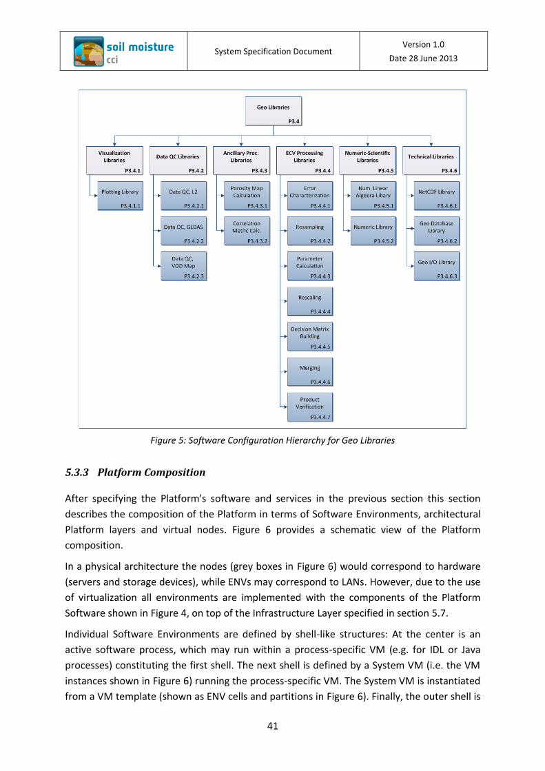
System Specification Document Version 1.0
Date 28 June 2013
41
Figure 5: Software Configuration Hierarchy for Geo Libraries
5.3.3 Platform Composition
After specifying the Platform's software and services in the previous section this section
describes the composition of the Platform in terms of Software Environments, architectural
Platform layers and virtual nodes. Figure 6 provides a schematic view of the Platform
composition.
In a physical architecture the nodes (grey boxes in Figure 6) would correspond to hardware
(servers and storage devices), while ENVs may correspond to LANs. However, due to the use
of virtualization all environments are implemented with the components of the Platform
Software shown in Figure 4, on top of the Infrastructure Layer specified in section 5.7.
Individual Software Environments are defined by shell-like structures: At the center is an
active software process, which may run within a process-specific VM (e.g. for IDL or Java
processes) constituting the first shell. The next shell is defined by a System VM (i.e. the VM
instances shown in Figure 6) running the process-specific VM. The System VM is instantiated
from a VM template (shown as ENV cells and partitions in Figure 6). Finally, the outer shell is
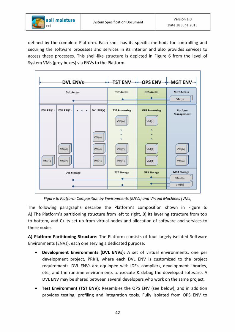
System Specification Document Version 1.0
Date 28 June 2013
42
defined by the complete Platform. Each shell has its specific methods for controlling and
securing the software processes and services in its interior and also provides services to
access these processes. This shell-like structure is depicted in Figure 6 from the level of
System VMs (grey boxes) via ENVs to the Platform.
Figure 6: Platform Composition by Environments (ENVs) and Virtual Machines (VMs)
The following paragraphs describe the Platform’s composition shown in Figure 6:
A) The Platform’s partitioning structure from left to right, B) its layering structure from top
to bottom, and C) its set-up from virtual nodes and allocation of software and services to
these nodes.
A) Platform Partitioning Structure: The Platform consists of four largely isolated Software
Environments (ENVs), each one serving a dedicated purpose:
Development Environments (DVL ENVs): A set of virtual environments, one per
development project, PRJ(i), where each DVL ENV is customized to the project
requirements. DVL ENVs are equipped with IDEs, compilers, development libraries,
etc., and the runtime environments to execute & debug the developed software. A
DVL ENV may be shared between several developers who work on the same project.
Test Environment (TST ENV): Resembles the OPS ENV (see below), and in addition
provides testing, profiling and integration tools. Fully isolated from OPS ENV to

System Specification Document Version 1.0
Date 28 June 2013
43
enable testing and demonstration of software without repercussions on the
operational services.
Operations Environment (OPS ENV): Provides the runtime environments (processing
VMs, web containers and other runtime services like databases, file systems, etc.) as
required for the execution of the System’s operational Application Software.
Platform Management Environment (MGT ENV): Provides all services as required for
administration and management of the Platform as a whole.
B) Platform Layering Structure: The Platform is stratified into three layers (from top to
bottom):
Access Layer: A layer for security and access control with firewalls, reverse proxies,
etc., isolating public services exposed to the Internet from internal services.
Process Layer: A layer for hosting the Application Software processes (in the DVL, TST
and OPS partitions) and Platform management services (in the MGT partition). This
layer provides the Platform’s computational and processing power.
Storage Layer: A layer for providing shared storage services to each partition in the
form of databases and file stores. There are operational and archive instances of data
stores: e.g. operational databases named dbd, dbt, dbo, dbm, and archive databases
named dbad, dbat, dbao, dbam; as well as operational file systems at mount points
/dvl, /tst, /ops, /mgt, and archive file systems at /arc/dvl, /arc/tst, /arc/ops,
/arc/mgt.
C) Platform Set-up from Virtual Nodes and Allocation: The virtual nodes are the Platform’s
building blocks; they are Virtual Machines (VMs) simulating standard x86 hardware
architectures. VMs are subject to the following conditions:
Each VM is equipped with a Guest OS, suitable libraries and runs services providing
an appropriate runtime environment for executing the desired software.
Application and Platform Software listed in the Software Configuration Hierarchies of
Figure 3 and Figure 4, respectively, are allocated to VM templates (the expressions
like “VM(2)” in Figure 6 are identifiers for such templates).
The allocation of OS and software to VM templates is performed dynamically during
the System’s operational use with the help of the Platform Management Software
and the Application Store (elements P4.2 and P4.1 in Figure 4, running as services in
VMs in the MGT ENV, i.e. VM(a) in Figure 6).
A VM instance can be created from a VM template by the Platform Operator or other
users with the permission to do so in accordance with the partitioning and layering

System Specification Document Version 1.0
Date 28 June 2013
44
constraints as described above. After instantiation, the VM is allocated to a particular
cell of the partitioned and layered grid in Figure 9.
VMs (i.e. instances) can be started and stopped by the Platform Operator or other
users having the relevant permission. (The grey boxes in Figure 6 symbolize individual
VM instances, e.g. VM(2) is instantiated three times in this example, once in each of
DVL PRJ(2), TST ENV and OPS ENV.)
Only the Platform Operator is allowed to move VM instances between cells of the
partitioned and layered grid.
A VM instance generally provides its services within the allocated partition (ENV) but
may also provide services to other partitions (ENVs) or to the Internet through the
Access Layer and depending on individually assigned access rights. Some examples
are shown by interface nodes in Figure 6, e.g. the interface nodes extending from
VM(db) to the partitions on the left.
The default access policy for the shared storage services VM(db) and VM(fs) is: An
ENV is granted read-access to databases and file systems of all ENVs to its right in
Figure 6 but has write-access only to its own database and file system. For security
reasons an ENV may overrule the default policy and restrict read-access for others for
certain of its data.
Virtualization software (hypervisors), Host OSes and basic services for managing and
instantiating VMs are provided by an underlying Infrastructure Layer (not shown in
Figure 6, but further described in the Infrastructure View in section 5.7).
Use of VMs as building blocks increases both the Platform’s robustness and its flexibility.
Application Software can be isolated from each other, and VMs can be dedicated to specific
projects and purposes, avoiding conflicts between application, library and OS versions. Due
to the virtualization, the allocation of software to nodes can be dynamically adapted to
changed requirements and can evolve together with the System.
The Platform's composition in terms of the four described partitions enables the isolation of
activities for different purposes: Development activities are strictly separated from testing &
demonstration activities, and both are isolated from System operations. A fourth isolated
activity is platform management, while common services are consistently provided to all
partitions and activities. This makes the software system very robust and reliable.
The model also greatly facilitates management, administration and confidence building
among the Platform users: It provides an area where software behavior can be
demonstrated and evaluated in a near-operational environment (TST ENV), and it allows
setting up a structured software development process, as specified in the Process View in
section 5.4.

System Specification Document Version 1.0
Date 28 June 2013
45
The Platform model furthermore clarifies some of the organizational roles introduced in the
Organization View (Figure 2 in section 5.2): The primary users of the DVL ENVs are the
Software Developers, those of the TST and OPS ENVs the Processing Engineers, and those of
the MGT ENV the Platform Operator and other users in a system management role.
5.4 Process View
The Process View is one of the two architectural views used in this document, which
describe the System’s dynamic behavior. It specifies the main processes to be implemented
in the System. Individual processes may interact with the external System Environment
specified by the Operational Scenarios. In contrast to the second dynamic view, the Use-
Case View in section 5.5 describing the System’s response to external actions, the Process
View references elements from the static architectural views in sections 5.1 and 5.2.
The inputs to the Process View are the main Operational Scenarios identified in section 3.1.
The Process View is constituted by the set of UML Activity diagrams and their corresponding
descriptions.
5.4.1 Data Acquisition Process
Figure 7 shows the data acquisition process, i.e. the flow of activities triggered by a Data
Provider publishing new L2 Data or Ancillary Data, which are required for the production of
the Soil Moisture ECV Data Products. A guiding principle for this activity flow is that data
acquisitions shall be made early and independently from the actual ECV Processing, as soon
as new data have been published, for the following reasons:
To perform an automatic Data QC check to confirm completeness and to reveal any
data issues;
To verify data with respect to its suitability for ECV Production in an interactive
review performed by Data Analysts in addition to the automatic Data QC;
To provide immediate feedback to Data Providers in case data issues were observed,
giving them the chance to fix issues before the next scheduled ECV Processing;
To avoid input data issues at the time when ECV Processing is scheduled to start;
To have the data available in the System for other evaluation, analysis or
development activities, that may be performed by Analysts or Scientists.
In Figure 7 newly available data are represented by the “DataProduct” UML object. This
object is understood to represent a specific type of L2 Data or Ancillary Data, as specified in
[SRD] section 5.1. It may represent a data product in its entirety, e.g. after reprocessing by
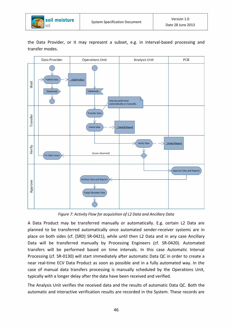
System Specification Document Version 1.0
Date 28 June 2013
46
the Data Provider, or it may represent a subset, e.g. in interval-based processing and
transfer modes.
Figure 7: Activity Flow for acquisition of L2 Data and Ancillary Data
A Data Product may be transferred manually or automatically. E.g. certain L2 Data are
planned to be transferred automatically once automated sender-receiver systems are in
place on both sides (cf. [SRD] SR-0421), while until then L2 Data and in any case Ancillary
Data will be transferred manually by Processing Engineers (cf. SR-0420). Automated
transfers will be performed based on time intervals. In this case Automatic Interval
Processing (cf. SR-0130) will start immediately after automatic Data QC in order to create a
near real-time ECV Data Product as soon as possible and in a fully automated way. In the
case of manual data transfers processing is manually scheduled by the Operations Unit,
typically with a longer delay after the data have been received and verified.
The Analysis Unit verifies the received data and the results of automatic Data QC. Both the
automatic and interactive verification results are recorded in the System. These records are

System Specification Document Version 1.0
Date 28 June 2013
47
represented by the DataQCReport and AnalystReport UML objects in Figure 7. Finally, the
PCB approves the data together with both reports.
The process completes with registration and copy of data and verification records to the
permanent Data Store and Data Archive and with the removal (purging) of any obsolete data
or reports that may still exist in temporary stores.
5.4.2 ECV Production Process
Figure 8 shows the flow of activities for the production of a Soil Moisture ECV Data Product,
be it for incremental extension of an existing product or full reprocessing. The original
initiative to start the production may come from anywhere. However, for the purpose of a
defined process the Analysis Unit formally initiates the production by issuing a Production
Request (represented by the “ProdRequest” UML object in the diagram). The Production
Request specifies the details of the Data Product to be produced and any complementary
data required for the production run. The process subsequently progresses through
preparation, generation and verification phases, and eventually completes with the
publication of the new ECV Data Product, which may be either a new version of a previously
published product, or an increment thereof, or the fully reprocessed data set, or even a new
Data Product.
Once the Production Request is available the Operations Unit checks if all preconditions are
met, that is, if the required input data are available in the System and have been verified and
approved. The Production Request is then submitted to the PCB for approval. The PCB
prioritizes Production Requests in order to manage data production with respect to Data
Users’ needs vs. the System’s production capacity, and issues Work Orders to the Operations
and Analysis Units to proceed with generation and verification.
The Operations Unit plans the production run. Then an assigned Processing Engineer
configures an instance of the ECV Processor that meets the requirements of the Production
Request. The full set of Configuration Parameters (shown as “ConfigPars” UML object in
Figure 8) is later attached to the Data Product to allow for a repetition of the production run
in the future.

System Specification Document Version 1.0
Date 28 June 2013
48
Figure 8: Activity Flow for the production of ECV Data Products

System Specification Document Version 1.0
Date 28 June 2013
49
After starting the ECV Processing the Processing Engineer monitors the running processes
and assures smooth processing by addressing technical issues which may be observed during
execution time. Individual processing runs may take weeks to months to complete (cf.
section 4.3, TM-014). Monitoring and issue fixing is supported by Process Monitoring &
Control software (item A3.6 in Figure 3). The Operations Unit may request support from
Analysis and Science Units in case issues related to the data or to Processing Algorithms are
detected. In extreme cases the production run is aborted if relevant problems cannot be
addressed within the production process. In such cases the PCB is involved to decide about
next steps.
Upon successful completion of the processing run the newly generated ECV Data Product is
available in the System’s temporary Data Store. The Processing Engineer uses the Data QC
software to check the new Data Product and to generate an automated Data QC Report. The
product generation phase completes with the Processing Engineer compiling a report (PE
Report) about the processing run including any events observed, issues detected and fixes or
workarounds applied.
The new ECV Data Product together with the automated Data QC Report and the PE Report
are made available to the Analysis Unit for interactive review and verification by Data
Analysts, whose verification results are documented in an Analyst Report. At this stage Data
Analysts and Processing Engineers may decide to fix observed issues or repeat parts of the
production run to address remaining issues. Upon positive verification the assembled
reports are submitted to the PCB for approval of the new product.
After approval the ECV Data Product, the applied configuration data, any intermediate data
to be preserved, and the verification records are registered and copied to the permanent
Data Store and Data Archive. Any obsolete data or reports that may still exist in temporary
stores are purged.
The process completes with the publication of the new ECV Data Product on the Soil
Moisture Web Portal making the new product available to the Data Users.
5.4.3 Software Change Process
Figure 9 shows the flow of activities associated with the resolution of reported software
issues, whether they are to be addressed by the implementation of software changes in the
Software Unit or by software installation or configuration changes in the Operations Unit.
The “Software User” column in Figure 9 represents both internal and external users. Data
Users, Data Analysts, Processing Engineers and Algorithm Developers are prominent
examples, but also Software Developers may be in the role of Software Users in the context
ofFigure 9.

System Specification Document Version 1.0
Date 28 June 2013
50
Figure 9: Activity flow for resolution of software issues, software development and testing

System Specification Document Version 1.0
Date 28 June 2013
51
Software issues are represented by the “Issue” UML object in Figure 9. An Issue is here
understood to represent any kind of software related request: a general problem report, a
specific bug report, an enhancement request, a request for installation & configuration or a
request for development of a new Software Application. An example may be an Algorithm
Developer who wants to update the ECV Processor with new Processing Algorithms and
submits an Issue with an appropriate enhancement request.
The software change process is supported by issue tracking software, which is used to
manage all reported Issues and related artifacts like assessment reports, implementation
proposals, test plans and test reports. The scope of reported Issues may widely vary from
trivial change requests to complete developments projects. Issues are first received and
assessed by the Operations Unit. Issues requiring changes to software applications and
source code are forwarded to the Software Unit.
The CCB prioritizes reported Issues and issues Work Orders to the Software Unit if required.
The CCB thus controls the development activities and balances them against available
development resources.
The Software Unit plans and implements software changes within the development
environments, i.e. the DVL ENVs shown in Figure 9. Software changes can also be
implemented by external Software Developers. Dedicated virtualized development
environments can be provided on DVL VMs together with the relevant development tools
and test data regardless of the physical location of the assigned developers.
The installation of a Change Request (CR) is then proposed to the CCB, which controls the
configuration of the TST and OPS ENVs. In cases where the Software Unit does not need to
be involved the Operations Unit can directly submit a CR.
Approved changes are installed and tested by the Operations Unit on the TST ENV, typically
based on release notes and test plans provided by the Software Unit or based on specific
change descriptions. The Operations Unit compiles a Test Report with the results of the test,
and in case of a positive test result, makes the Software changes available for user testing by
the Software Users, still on the TST ENV. If the Software Users report no relevant Issues
related to the tested change the Operations Unit submits an OPS CR to promote the changes
to the OPS ENV.
The deployment to the OPS ENV is again done after approval by the CCB. Once deployed to
the OPS ENV, the updated Software is ready for operational use. The Software Users may
submit further Issues if new problems are observed or a need to change the software has
been identified.

System Specification Document Version 1.0
Date 28 June 2013
52
5.4.4 ECV Change Process
This subsection will be provided in version 2 of this document.
5.5 Use-Case View
This section specifies interactions of external Actors with the System in a Use-Case View. The
View describes the System’s response to externally initiated actions, while internally
initiated actions and activities are specified by the Process View in section 5.4. The view is
constituted by the set of Use Cases listed in Table 22:
Table 22: Main Use Cases of the Soil Moisture ECVPS
UC-# Main Actor Goal
UC-001 Data User Download ECV Data Product
UC-002 Data User View ECV Data Product
UC-003 Data User Compare ECV Data Products
Each Use Case has a unique identifier and is described in the format shown in Table 23. Use
Case descriptions typically do not refer to internal System Elements but treat the System as a
single entity, which interacts with the Actors of the Use Case.
Table 23: Template for Use Cases (UCs)
Use Case Name: A unique name given as a description of a User Goal
Unique ID UC-#
Primary Actor Initiator of the interaction, typically the person having the User Goal.
Preconditions What must be the case for the Use Case to start.
Success Guarantees
What will be the outcome of the Use Case.
Main Success Scenario
1. First step.
2. Second step.
3. …
n. Last step.
Extensions Alternative scenarios and outcomes amending or substituting specific steps.
Source Reference to requirements, documents or persons with relevant input to the UC.
Priority Priority value from MoSCoW schema as described in [SRD], section 3.7.
Comments Any other comments for clarification and future consideration.
The Soil Moisture ECVPS seen from outside as a single entity has only a small set of external
User Goals, namely those identified in section 3.1 and listed in Table 22. There is a single

System Specification Document Version 1.0
Date 28 June 2013
53
external Actor, the Data User who approaches the Soil Moisture ECVPS in this way. Other
external entities from Science Communities, Data Providers, Software Developers, Hosting
Organization and Sponsors are integrated with the System’s organization and processes (for
example via their participation in the PCB and CCB boards); their interactions with the
System are therefore described in the Process View in section 5.4.
Table 24: (UC-001) Download ECV Data Product
Use Case Name: Download ECV Data Product
Unique ID UC-001
Primary Actor Data User
Preconditions User is registered at Soil Moisture Web Portal and duly authorized for data download.
ECV Data Product was published and is available in System’s File Store.
Success Guarantees
ECV Data Product has been downloaded to User’s local environment.
Main Success Scenario
1. User logs into Soil Moisture Web Portal.
2. Soil Moisture Web Portal checks credentials and admits User.
3. User navigates to the desired ECV Data Product and selects download link.
4. Soil Moisture Web Portal checks User’s permissions and admits User.
5. Soil Moisture Web Portal sends an email to User’s registered email address with download instructions and temporary login credentials for System’s FTP download server.
6. User connects to FTP download server with their preferred FTP client.
7. User initiates FTP download and waits until download has completed.
8. User verifies in the local environment that the data was received and can be used for further analysis and visualization using local tools.
Extensions 2a. If User is not admitted, Soil Moisture Web Portal displays a self-registration page allowing the User to register and request permission for data download.
4a. If User is not admitted, Soil Moisture Web Portal displays an administration page allowing the User to request permission for data download.
Source [SRD] SR-0210, SR-0460, SR-0470, SR-0480, SR-0490
Priority MUST-HAVE
Comments Soil Moisture Web Portal may be entered from the common CCI Web Portal.
If requirement SR-0210 in [SRD] can be relaxed it may be recommendable to replace FTP by HTTP(s) for data download.
Table 25: (UC-002) View ECV Data Product
Use Case Name: View ECV Data Product
Unique ID UC-002
Primary Actor Data User
Preconditions The ECV Data Product of interest was published and is available on System’s File Store.

System Specification Document Version 1.0
Date 28 June 2013
54
Use Case Name: View ECV Data Product
Success Guarantees
Subsets of ECV Data Product raster images and timeseries data have been viewed by User in a web browser.
Main Success Scenario
1. User navigates his web browser to Soil Moisture Web Portal.
2. User navigates to the desired ECV Data Product and selects the view link.
3. User’s web browser displays the Data Viewer page showing the selected ECV Data Product at the last available data day.
4. User uses Data Viewer’s inline zoom, pan and calendar tools to select the spatial-temporal area of interest.
5. User views ECV Data Product raster images overlayed on a geographic map and may select a geographic point of interest to display timeseries data for the selected point.
Extensions 4a. User may use Data Viewer’s inline product selection tool to navigate to a different product or product version.
Source [SRD] SR-0620
Priority MUST-HAVE
Comments Soil Moisture Web Portal may be entered from the common CCI Web Portal.
Table 26: (UC-003) Compare ECV Data Products
Use Case Name: Compare ECV Data Products
Unique ID UC-003
Primary Actor Data User
Preconditions The ECV Data Products of interest were published and are available on System’s File Store.
Success Guarantees
Spatial-temporally linked subsets of up to four ECV Data Products have been compared by User in a web browser.
Main Success Scenario
1. User performed UC-002, View ECV Data Product, and views the spatial-temporal subset of interest.
2. User uses Data Viewer’s inline map utilities to display up to four maps in a side-by-side view and has the option to mutually link maps spatially and/or temporally.
3. Individually per displayed map, User uses Data Viewer’s inline product selection tool to navigate to a product or product version of interest.
4. In one of the displayed maps, User uses Data Viewer’s inline zoom, pan and calendar tools to select the spatial-temporal area of interest.
5. Data Viewer synchronizes and updates other displayed maps in correspondence with the selected link modes.
6. User compares ECV Data Product raster images overlaid on geographic maps side-by-side, and may select individually per displayed map a geographic point of interest to display and compare its timeseries data.
Extensions
Source [SRD] SR-0630
Priority MUST-HAVE

System Specification Document Version 1.0
Date 28 June 2013
55
Use Case Name: Compare ECV Data Products
Comments Soil Moisture Web Portal may be entered from the common CCI Web Portal.
5.6 Information View
This section will be provided in version 2 of this document.
5.7 Infrastructure View
This section specifies the Hardware and Software Infrastructure required to run the
Application and Platform Software, as specified in the Software View in section 5.3. Three
basic options to establish the System’s Infrastructure Layer are discussed:
A. Dedicated hardware in conjunction with Linux-based Host OS and virtualization
software (hypervisor).
B. Deployment on a Cloud Computing Infrastructure.
C. A heterogeneous infrastructure combining both options A and B.
Option A can be implemented with a hardware configuration as specified in [SRD] section
6.5.3. This configuration permits the complete deployment of Platform Software and
Application Software on a dedicated, hardware-based and isolated computing infrastructure.
The performance observed for the Soil Moisture Prototype ECVPS (SM PECVPS) in the ESA
CCI Phase 1 Soil Moisture project confirms that the specified hardware configuration will
meet the minimum performance requirement [SRD] SR-0370 (cf. also the key characteristics
in [SRD] section 4.3). However, this performance requirement may soon be overtaken by
events with data coming in from new satellite instruments. In order to speed up ECV
processing additional computing power for the OPS LAN in conjunction with software and
methods for parallel computing and scaling would thus be required, cf. the discussion in
section 4.3, TM-014.
Option B uses a Cloud Infrastructure Service (IaaS) offered by a Commercial (Public) Cloud
Provider, or a similar Private Cloud Infrastructure maintained by the Hosting Organization.
This is possible because the System’s software architecture, as specified in the Software
View of section 5.3, is a) based on virtualization technology and b) designed to be fit for a
Cloud Computing Architecture, as described by the UCSB-IBM Cloud Computing
Classification Model [Ahson11]. The three subsets of Cloud services map to the System’s
software as follows:
The Soil Moisture ECV Application Software, as specified in section 5.3.1, could be
provided as Cloud Software as a Service (SaaS).

System Specification Document Version 1.0
Date 28 June 2013
56
The Soil Moisture ECV Platform of Software Environments, as specified in sections
5.3.2 and 5.3.3, could be provided as Cloud Platform as a Service (PaaS).
The former two elements are to be deployed on top of a Cloud Infrastructure as a
Service (IaaS) offered by a Public Cloud Provider or a Private Cloud Infrastructure.
In order to accommodate the System’s base workload computational, storage and
communication resources acquired from a Cloud IaaS Provider will need to correspond
approximately to the hardware configuration, as specified in [SRD] section 6.5.3. The Cloud
setup has the important advantage that resources can scale up on demand, but they can
only be efficiently used for processing if the ECV Processor is designed to use the Cloud’s
elastic compute feature, i.e. processing can be parallelized (cf. the discussion in section 4.3,
TM-014).
Option B is currently being prototyped and evaluated under ESA’s EP4SM project. Figure 10
copied from [EP4SM-SAD] shows the architecture of a suitable Cloud Infrastructure as
required for deployment of the Soil Moisture ECVPS.
Figure 10: Cloud infrastructure for deployment of the Soil Moisture ECVPS
The Cloud architecture shown in Figure 10 contains the three layers SaaS, PaaS and IaaS as
follows:
The SaaS layer provides the System’s software applications to all application users. For
example external Data Users will perform their Use Cases through a web portal. Included are
System Specification Document Version 1.0
Date 28 June 2013
57
also all internally used applications, e.g. for data acquisition, processing and analysis. They
can be provided as SaaS if they are designed to be called via a web service API.
The PaaS layer provides the capabilities, which are required to develop, test and operate the
System’s software. It is controlled and monitored by software for Application Store and
Platform Management and Supporting Services. The PaaS layer provides VM templates for
runtime, development and testing environments with the compiler, development and
profiling tools preconfigured for developers. The primary users of this layer are the Software
Developers and Processing Engineers who implement system changes. Instantiated
development, testing and operations environments are isolated from each other and
mapped to application groups in individual Virtual Machines.
The IaaS layer provides the System’s computational, storage and networking resources and
includes host Operating Systems, the virtualization software stack (hypervisors) and Cloud
Orchestration Software. This layer can be implemented either via an IaaS Cloud Provider or
via a private Cloud Infrastructure of the Hosting Organization. It is deployed on top of a
Hardware Infrastructure consisting of physical servers, storage and networking equipment.
Option C, deployment on a heterogeneous Cloud, combines the local Private Cloud
computing infrastructure with an externally provided commercial Cloud Infrastructure. In
this scenario the base system can be operated on the local infrastructure, while peak
demands can be addressed by temporarily increased external Cloud resources. As already
discussed for Option B, the scaling potential of a Cloud infrastructure can only be efficiently
used if the ECV Processor is designed for process parallelization. Temporarily increased
Cloud resources may further be useful to host collaborative projects or activities within the
Science Community or with external Software Developers. In such cases additional DVL and
TST ENVs could be deployed in the extended Cloud infrastructure.
5.8 Life Cycle Sustainment Activities
This section will be provided in version 2 of this document.
6 Traceability Matrix
This section will be provided in version 2 of this document.