Embed Size (px)
Citation preview

System on Chip Battery State Estimator:E-Bike Case Study
Rocco Morello, Roberto Di Rienzo, Federico Baronti, Roberto Roncella and Roberto SalettiDip. di Ingegneria dell’Informazione, Universita di Pisa, Pisa, Italy
Abstract—This paper discusses the hardware implementationand experimental validation of a model-based battery stateestimator. The model parameters are identified online usingthe moving window least squares method. The estimator isimplemented in a field programmable gate array device as ahardware block, which interacts with the embedded processorto form a system on a chip battery management system (BMS).As a case study, the BMS is applied to the battery pack of ane-bike. Road tests show that the implemented estimator mayprovide very good performance in terms of maximum and rmsestimation errors. This work also proposes a new methodologyto assess the performance of a battery state estimator.
I. INTRODUCTION
Lithium-ion batteries allow the implementation of light on-board energy storage systems (ESS), thanks to their highpower and energy densities. The ESS must be equipped witha battery management system (BMS) in order to ensure areliable and safe operation of the battery. The BMS monitorsand controls the charge and discharge phases by estimatingthe battery state. The most important state variables are thebattery state of charge (SOC) and state of health (SOH). SOCis related to the residual charge stored in the battery and SOHquantifies its degradation in terms of capacity fading and theincrease of the internal resistance [1], [2].
The BMS executes algorithms that use quantities directlyobservable on the cells, i.e., their voltage, current and tempera-ture. Many algorithms have been proposed for SOC estimation,starting from the Coulomb Counting (CC), which is based onthe integration over time of the battery current. The integrationresult is normalized with respect to the cell capacity. TheCC must be initialized with the correct value of the SOCand the current must be measured by a high accuracy sensor,in order to avoid the intrinsic divergence in the integration.Another simple method is based on the open circuit voltage(VOC) measurement. In fact, VOC mainly depends on SOCand slightly on other factors, such as temperature, ageing andcurrent rate [3]. However, the cell voltage relaxes to VOC
a long time after the cell current is interrupted. Thus, thistechnique cannot be used in highly dynamic systems [4].
High accuracy and reliability are required in automotiveapplications, in order to guarantee the safety standard and agood estimation of the vehicle autonomy. Furthermore, thealgorithms must be executed in real-time in an embeddedsystem, like the BMS. Model-based algorithms, such as theExtended Kalman Filter (EKF) [5], [6], the Mix Algorithm[7] and the Adaptive Mix Algorithm (AMA) [4] are adopted.A model-based technique is a closed-loop method in which the
model is used to correct the estimated SOC, by comparing thevoltage predicted by the model with the measured one. Variouskinds of model can be used [8], but an Electrical Circuit Model(ECM) has some benefits when used in a real-time embeddedsystem [9]. The accuracy of the SOC estimate depends on theECM capability to predict the cell voltage, in all the operatingconditions and for the entire battery life. A good approach isto track the variation of the operating condition online, whichis the solution adopted in the EKF and AMA techniques.
The AMA uses an enhanced version of the Mix Algorithm,in which SOC estimation is corrected by using an ECMwhere the parameters are updated online by using the MovingWindow Least Squares (MWLS) method [10], [11], insteadof taking them constant, like in the original algorithm. Theperformance of this algorithm has been evaluated by com-paring it to the EKF method [4], [12], which is the mostused in this field. The comparison, carried out with currentand voltage profiles obtained from the Urban DynamometerDriving Schedule (UDDS) driving cycle, defined by the U.S.Environmental Protection Agency [13], shows that both meth-ods provide good estimation of both parameters and SOC.Both EKF and AMA are suitable for an embedded systemimplementation.
An attractive solution for industrial and automotive ap-plications is the use of a low-cost field-programmable gatearray (FPGA). The estimators can be implemented on theFPGA as hardware accelerators beside the processor, whichis fully dedicated to the other BMS functionalities. A firsthardware implementation of the non adaptive version of theMix algorithm is reported in [14]. A hardware-in-the-Loop(HiL) simulation framework used to test and compare theAMA and EKF, implemented in hardware on an FPGA, ispresented in [15]. In this framework, a multi-cell battery issimulated using an accurate model.
An experiment not common in literature that can providefinal results is to test the estimators in a real application. Thisallows an effective measurement of the estimator performance,as well as the analysis of the issues arising from its integrationin a real system. The aim of this paper is to present the resultsobtained using the AMA in a real application, i.e., on an e-bike. A simple BMS provided with the AMA battery state esti-mator has been implemented as a system on chip on an AlteraCyclone® V. The algorithm details and the hardware/softwarepartitioning of the system are discussed in Section II. Theexperimental testbed description is reported In Section III,while Section IV describes the methodology applied to assess
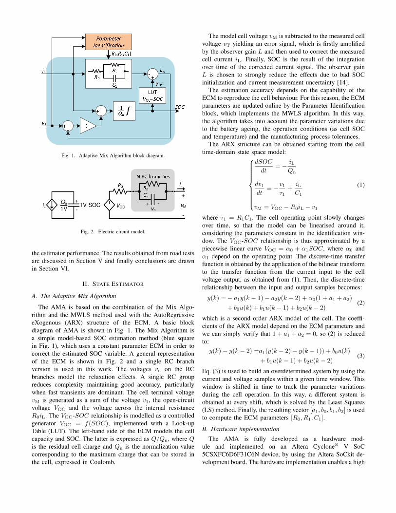
Fig. 1. Adaptive Mix Algorithm block diagram.
1V SOC
Qn iL
+
-
VOC+ -
vn
+
-
vM
iL
1V
Fig. 2. Electric circuit model.
the estimator performance. The results obtained from road testsare discussed in Section V and finally conclusions are drawnin Section VI.
II. STATE ESTIMATOR
A. The Adaptive Mix Algorithm
The AMA is based on the combination of the Mix Algo-rithm and the MWLS method used with the AutoRegressiveeXogenous (ARX) structure of the ECM. A basic blockdiagram of AMA is shown in Fig. 1. The Mix Algorithm isa simple model-based SOC estimation method (blue squarein Fig. 1), which uses a constant parameter ECM in order tocorrect the estimated SOC variable. A general representationof the ECM is shown in Fig. 2 and a single RC branchversion is used in this work. The voltages vn on the RCbranches model the relaxation effects. A single RC groupreduces complexity maintaining good accuracy, particularlywhen fast transients are dominant. The cell terminal voltagevM is generated as a sum of the voltage v1, the open-circuitvoltage VOC and the voltage across the internal resistanceR0iL. The VOC-SOC relationship is modelled as a controlledgenerator VOC = f(SOC), implemented with a Look-upTable (LUT). The left-hand side of the ECM models the cellcapacity and SOC. The latter is expressed as Q/Qn, where Qis the residual cell charge and Qn is the normalization valuecorresponding to the maximum charge that can be stored inthe cell, expressed in Coulomb.
The model cell voltage vM is subtracted to the measured cellvoltage vT yielding an error signal, which is firstly amplifiedby the observer gain L and then used to correct the measuredcell current iL. Finally, SOC is the result of the integrationover time of the corrected current signal. The observer gainL is chosen to strongly reduce the effects due to bad SOCinitialization and current measurement uncertainty [14].
The estimation accuracy depends on the capability of theECM to reproduce the cell behaviour. For this reason, the ECMparameters are updated online by the Parameter Identificationblock, which implements the MWLS algorithm. In this way,the algorithm takes into account the parameter variations dueto the battery ageing, the operation conditions (as cell SOCand temperature) and the manufacturing process tolerances.
The ARX structure can be obtained starting from the celltime-domain state space model:
dSOC
dt= − iL
Qn
dv1dt
= −v1τ1
+iLC1
vM = VOC −R0iL − v1
(1)
where τ1 = R1C1. The cell operating point slowly changesover time, so that the model can be linearised around it,considering the parameters constant in the identification win-dow. The VOC-SOC relationship is thus approximated by apiecewise linear curve VOC = α0 + α1SOC, where α0 andα1 depend on the operating point. The discrete-time transferfunction is obtained by the application of the bilinear transformto the transfer function from the current input to the cellvoltage output, as obtained from (1). Then, the discrete-timerelationship between the input and output samples becomes:
y(k) = − a1y(k − 1) − a2y(k − 2) + α0(1 + a1 + a2)
+ b0u(k) + b1u(k − 1) + b2u(k − 2)(2)
which is a second order ARX model of the cell. The coeffi-cients of the ARX model depend on the ECM parameters andwe can simply verify that 1 + a1 + a2 = 0, so (2) is reducedto:y(k) − y(k − 2) =a1(y(k − 2) − y(k − 1)) + b0u(k)
+ b1u(k − 1) + b2u(k − 2)(3)
Eq. (3) is used to build an overdetermined system by using thecurrent and voltage samples within a given time window. Thiswindow is shifted in time to track the parameter variationsduring the cell operation. In this way, a different system isobtained at every shift, which is solved by the Least Squares(LS) method. Finally, the resulting vector [a1, b0, b1, b2] is usedto compute the ECM parameters [R0, R1, C1].
B. Hardware implementation
The AMA is fully developed as a hardware mod-ule and implemented on an Altera Cyclone® V SoC5CSXFC6D6F31C6N device, by using the Altera SoCkit de-velopment board. The hardware implementation enables a high
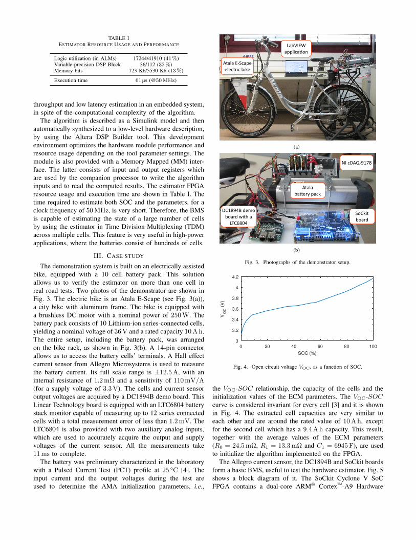
TABLE IESTIMATOR RESOURCE USAGE AND PERFORMANCE
Logic utilization (in ALMs) 17244/41910 (41%)Variable-precision DSP Block 36/112 (32%)Memory bits 723 Kb/5530 Kb (13%)
Execution time 61 µs (@50MHz)
throughput and low latency estimation in an embedded system,in spite of the computational complexity of the algorithm.
The algorithm is described as a Simulink model and thenautomatically synthesized to a low-level hardware description,by using the Altera DSP Builder tool. This developmentenvironment optimizes the hardware module performance andresource usage depending on the tool parameter settings. Themodule is also provided with a Memory Mapped (MM) inter-face. The latter consists of input and output registers whichare used by the companion processor to write the algorithminputs and to read the computed results. The estimator FPGAresource usage and execution time are shown in Table I. Thetime required to estimate both SOC and the parameters, for aclock frequency of 50 MHz, is very short. Therefore, the BMSis capable of estimating the state of a large number of cellsby using the estimator in Time Division Multiplexing (TDM)across multiple cells. This feature is very useful in high-powerapplications, where the batteries consist of hundreds of cells.
III. CASE STUDY
The demonstration system is built on an electrically assistedbike, equipped with a 10 cell battery pack. This solutionallows us to verify the estimator on more than one cell inreal road tests. Two photos of the demonstrator are shown inFig. 3. The electric bike is an Atala E-Scape (see Fig. 3(a)),a city bike with aluminum frame. The bike is equipped witha brushless DC motor with a nominal power of 250 W. Thebattery pack consists of 10 Lithium-ion series-connected cells,yielding a nominal voltage of 36 V and a rated capacity 10 A h.The entire setup, including the battery pack, was arrangedon the bike rack, as shown in Fig. 3(b). A 14-pin connectorallows us to access the battery cells’ terminals. A Hall effectcurrent sensor from Allegro Microsystems is used to measurethe battery current. Its full scale range is ±12.5 A, with aninternal resistance of 1.2 mΩ and a sensitivity of 110 mV/A(for a supply voltage of 3.3 V). The cells and current sensoroutput voltages are acquired by a DC1894B demo board. ThisLinear Technology board is equipped with an LTC6804 batterystack monitor capable of measuring up to 12 series connectedcells with a total measurement error of less than 1.2 mV. TheLTC6804 is also provided with two auxiliary analog inputs,which are used to accurately acquire the output and supplyvoltages of the current sensor. All the measurements take11 ms to complete.
The battery was preliminary characterized in the laboratorywith a Pulsed Current Test (PCT) profile at 25 C [4]. Theinput current and the output voltages during the test areused to determine the AMA initialization parameters, i.e.,
(a)
(b)
Fig. 3. Photographs of the demonstrator setup.
SOC (%)
0 20 40 60 80 1003
3.2
3.4
3.6
3.8
4
4.2
VO
C (
V)
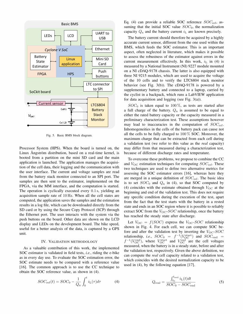
Fig. 4. Open circuit voltage VOC, as a function of SOC.
the VOC-SOC relationship, the capacity of the cells and theinitialization values of the ECM parameters. The VOC-SOCcurve is considered invariant for every cell [3] and it is shownin Fig. 4. The extracted cell capacities are very similar toeach other and are around the rated value of 10 A h, exceptfor the second cell which has a 9.4 A h capacity. This result,together with the average values of the ECM parameters(R0 = 24.5 mΩ, R1 = 13.3 mΩ and C1 = 6945 F), are usedto initialize the algorithm implemented on the FPGA.
The Allegro current sensor, the DC1894B and SoCkit boardsform a basic BMS, useful to test the hardware estimator. Fig. 5shows a block diagram of it. The SoCkit Cyclone V SoCFPGA contains a dual-core ARM® Cortex™-A9 Hardware
!
!
!"
##$
%&'(
!
Fig. 5. Basic BMS block diagram.
Processor System (HPS). When the board is turned on, theLinux Angstrom distribution, based on a real-time kernel, isbooted from a partition on the mini SD card and the mainapplication is launched. The application manages the acquisi-tion of the cell data, their logging and the communication withthe user interface. The current and voltage samples are readfrom the battery stack monitor connected to an SPI port. Thesamples are then sent to the estimator, implemented on theFPGA, via the MM interface, and the computation is started.The operation is cyclically executed every 0.1 s, yielding anacquisition sample rate of 10 Hz. When all the cell states arecomputed, the application saves the samples and the estimationresults in a log file, which can be downloaded directly from theSD card or by using the Secure Copy Protocol (SCP) throughthe Ethernet port. The user interacts with the system via thepush buttons on the board. Other data are shown on the LCDdisplay and LEDs on the development board. The bike speed,useful for a better analysis of the data, is captured by a GPSunit.
IV. VALIDATION METHODOLOGY
As a valuable contribution of this work, the implementedSOC estimator is validated in field tests, i.e., riding the e-bikeas in every day use. To evaluate the SOC estimation error, theSOC estimate needs to be compared with a reference value[16]. The common approach is to use the CC technique toobtain the SOC reference value, as shown in (4).
SOCref(t) = SOC0 −1
Qn
∫ t
0
iL(τ)dτ (4)
Eq. (4) can provide a reliable SOC reference SOCref , as-suming that the initial SOC value SOC0, the normalizationcapacity Qn and the battery current iL are known precisely.
The battery current should therefore be acquired by a highlyaccurate current sensor, different from the one used within theBMS, which feeds the SOC estimator. This is an importantaspect, often neglected in literature, which makes it possibleto assess the robustness of the estimator against errors in thecurrent measurement effectively. In this work, iL in (4) ismeasured by a National Instrument (NI) 9227 module mountedon a NI cDAQ-9178 chassis. The latter is also equipped withthree NI 9215 modules, which are used to acquire the voltageof the 10 cells and to verify the LTC6804 stack monitorbehavior (see Fig. 3(b)). The cDAQ-9178 is powered by asupplementary battery and connected to a laptop, carried bythe cyclist in a backpack, which runs a LabVIEW applicationfor data acquisition and logging (see Fig. 3(a)).
SOC0 is taken equal to 100 %, as tests are started aftera full charge of the battery. Qn is assumed to be equal toeither the rated battery capacity or the capacity measured in apreliminary characterization test. These assumptions howevermay lead to inaccuracies in the computation of SOCref .Inhomogeneities in the cells of the battery pack can cause notall the cells to be fully charged to 100 % SOC. Moreover, themaximum charge that can be extracted from each cell duringa validation test (we refer to this value as the real capacity)may differ from that measured during a characterization test,because of different discharge rates and temperature.
To overcome these problems, we propose to combine the CCand VOC estimation techniques for computing SOCref . Thesetwo techniques are used to define two alternative metrics forassessing the SOC estimator errors [16], whereas here theyare merged in a unique definition of SOCref . The basic ideais to set SOC0 and Qn in (4), so that SOC computed by(4) coincides with the estimate obtained through VOC at thebeginning and end of the validation test. This does not requireany specific condition during the execution of the test, apartfrom the fact that the test starts with the battery in a restedstate and ends in an SOC region where it is possible to reliablyextract SOC from the VOC-SOC relationship, once the batteryhas reached the steady state after discharge.
Let VOC = f(SOC) express the VOC-SOC relationshipshown in Fig. 4. For each cell, we can compute SOC be-fore and after the validation test by inverting the VOC-SOCrelationship, i.e., SOC0 = f−1(V start
OC ) and SOCend =f−1(V end
OC ), where V startOC and V end
OC are the cell voltagesmeasured, when the battery is in a steady state, before and afterthe validation test, respectively. Given the above definition, wecan compute the real cell capacity related to a validation test,which coincides with the desired normalization capacity to beused in (4), by the following equation [17].
Qreal =
∫ tendt0
iL(t)dt
SOC0 − SOCend(5)

Time (min)
0 25 50 75 100 125
Pe (
W)
0
100
200
300
400
500
0
10
20
30
40
50
Speed (
Km
/h)
Fig. 6. Electric power and speed during the discussed validation test.
Cell
1 2 3 4 5 6 7 8 9 108.5
9
9.5
10
10.5
Capacity (
Ah)
Rated
PCT
Real
Fig. 7. Capacities of the cells extracted using the PCT and the discussedvalidation test.
V. EXPERIMENTAL RESULTS
Several road tests have been carried out, proving boththe functionality of the basic BMS provided with the AMAestimator and the effectiveness of the designed experimentalset-up. As a representative example, we discuss the resultsobtained during a validation test, consisting of the repetitionsof a cycling period followed by a rest pause. The electricpower Pe provided by the battery pack and the speed measuredby the GPS data logger during the test are shown in Fig. 6.
First of all, we compute the initial SOC and the real capacityof each cell of the battery pack from the data acquired by theNI cDAQ-9178 chassis. Then, we evaluate the correspondingSOC reference using (4). Fig. 7 shows the real cell capacity,for the discussed test, and compares it to the value obtainedin the PCT characterization test. Apart from the second cell,which presents a pronounced degradation of the cell capacity,there is only a slight difference between the PCT, ratedand real cell capacities, as expected by the high Coulombicefficiency provided by the Lithium-ion battery technology. Thecomputed SOCref(t) for each cell is reported in Fig. 8, whereit is evident that the SOC of the second cell corresponds tothe battery SOC, as the second cell is the first cell to reachthe discharge cut-off voltage.
With the availability of the SOC reference, we can calculatethe estimation error introduced by the AMA. The AMASOC estimate for the second cell is shown in Fig. 9 and isvery close to the reference value during all the test. On thecontrary, the pure uncompensated CC drifts over time. This
Time (min)
0 25 50 75 100 12510
20
30
40
50
60
70
80
90
100
SO
C (
%)
Cell 1
Cell 2
Cell 3
Cell 4
Cell 5
Cell 6
Cell 7
Cell 8
Cell 9
Cell 10
Fig. 8. SOC behavior of the 10 cells during the discussed validation test.
Time (min)
0 25 50 75 100 1250
20
40
60
80
100
SO
C (
%)
Ref
AMA
CC
Fig. 9. Comparison of the SOC estimation results for the second cell.
clearly demonstrates that the AMA is capable of correctingthe uncertainties in the current measurement (especially theoffset of the current sensor) and in the real capacity of thecell.
Table II shows the maximum and rms errors of the AMAand CC SOC estimations. The AMA provides a more reliableestimation than CC, being its rms error below 2 % and themaximum absolute error around 3 %, for all the battery cells.This is a valuable achievement, as it is obtained in road tests,when the battery is subjected to the real application load. Infact, if we consider the SOC estimation errors reported in[6] for a similar application, AMA outperforms EKF, as thelatter introduces a maximum SOC error well above 5 %. Betterperformance in terms of maximum error is obtained in [6]using an Adaptive EKF, at the expense of higher complexity.It is worth noting that the results reported in [6] refer tolaboratory tests and not to road tests, as in this work.
Finally, Fig. 10 shows the R0 and τ1 ECM parametersidentified by the AMA for the second cell. While the R0
identification is robust against the choice of the window length,τ1 identification seems to be sensitive to this choice. Theresults reported in Fig. 10 refer to a window length of 20 minand an LS matrix with 30 rows. This implies that the ECM

TABLE IISOC ESTIMATION ERRORS
AMA CCMax (%) rms (%) Max (%) rms (%)
Cell 1 2.4 1.2 2.7 1.5Cell 2 3.0 1.7 9.3 5.9Cell 3 3.2 1.7 2.8 1.6Cell 4 2.2 1.1 3.1 1.8Cell 5 3.2 1.5 2.4 1.3Cell 6 3.4 1.7 3.1 1.8Cell 7 3.1 1.6 3.4 2.0Cell 8 2.6 1.3 2.5 1.4Cell 9 2.7 1.3 2.1 1.1Cell 10 2.5 1.2 3.2 1.9
10
15
20
25
30
R0 (
mΩ
)
Time (min)
0 25 50 75 100 1250
25
50
75
100
τ1 (
s)
Fig. 10. ECM parameters estimated online by the AMA for the second cell.
parameters are updated every 40 s. Even if the windows inwhich the battery current is almost constant are discarded, theidentification of τ1 is less reliable, when the window overlapsa rest period.
VI. CONCLUSIONS
This work has demonstrated the implementation of a batterystate estimator in an industrial FPGA. The estimator is basedon the AMA and is implemented as a hardware acceleratorblock, which interacts to the processor embedded in the FPGAto form a system on a chip BMS. Thanks to its effectivedesign, the estimator module can be used to estimate the stateof all the cells in the battery pack in a time multiplexingfashion. As a case study, we have integrated the BMS intothe battery pack of an e-bike. This allowed us to validate theestimator in a real application scenario, which represents asignificant achievement, as almost all the literature on thistopic reports on experimental results obtained in laboratorytests and for a single cell. The road tests carried out haveshown the effectiveness of the designed BMS and experimentalset-up, and that the AMA estimator provides a very goodestimation comparable or even better than the well establishedEKF.
ACKNOWLEDGMENT
The authors would like to thank Alessio Tarabori and theSystem Solution Engineering group of Altera now part ofIntel for the support and fruitful discussion on the topicof this paper. This work has been funded by the ECSELJoint Undertaking under grant agreement No. 662192 (3CCarproject).
REFERENCES
[1] H. Rahimi-Eichi, U. Ojha, F. Baronti, and M.-Y. Chow, “BatteryManagement System: An Overview of Its Application in the SmartGrid and Electric Vehicles,” IEEE Ind. Electron. Mag., vol. 7, no. 2,pp. 4–16, Jun. 2013.
[2] Dai Haifeng, Wei Xuezhe, and Sun Zechang, “A new SOH predictionconcept for the power lithium-ion battery used on HEVs,” in 2009IEEE Veh. Power Propuls. Conf. IEEE, Sep. 2009, pp. 1649–1653.
[3] B. Pattipati, B. Balasingam, G. Avvari, K. Pattipati, and Y. Bar-Shalom,“Open circuit voltage characterization of lithium-ion batteries,” J.Power Sources, vol. 269, pp. 317–333, Dec. 2014.
[4] R. Morello, W. Zamboni, F. Baronti, R. D. Rienzo, R. Roncella,G. Spagnuolo, and R. Saletti, “Comparison of State and ParameterEstimators for Electric Vehicle Batteries,” in IECON 2015 - 41st Annu.Conf. IEEE Ind. Electron. Soc., 2015, pp. 5433–5438.
[5] G. L. Plett, “Extended Kalman filtering for battery managementsystems of LiPB-based HEV battery packs: Part 3. State and parameterestimation,” J. Power Sources, vol. 134, no. 2, pp. 277–292, Aug. 2004.
[6] C. Taborelli and S. Onori, “State of charge estimation using extendedKalman filters for battery management system,” in 2014 IEEE Int.Electr. Veh. Conf. IEEE, Dec. 2014, pp. 1–8.
[7] F. Codeca, S. M. Savaresi, and G. Rizzoni, “On battery State of Chargeestimation: A new mixed algorithm,” in 2008 IEEE Int. Conf. ControlAppl. IEEE, Sep. 2008, pp. 102–107.
[8] V. Ramadesigan, P. W. C. Northrop, S. De, S. Santhanagopalan,R. D. Braatz, and V. R. Subramanian, “Modeling and Simulation ofLithium-Ion Batteries from a Systems Engineering Perspective,” J.Electrochem. Soc., vol. 159, no. 3, pp. R31–R45, Jan. 2012.
[9] M. Chen and G. Rincon-Mora, “Accurate Electrical Battery ModelCapable of Predicting Runtime and I-V Performance,” IEEE Trans.Energy Convers., vol. 21, no. 2, pp. 504–511, Jun. 2006.
[10] H. Rahimi-Eichi, F. Baronti, and M.-Y. Chow, “Modeling andonline parameter identification of Li-Polymer battery cells for SOCestimation,” in 2012 IEEE Int. Symp. Ind. Electron. IEEE, May 2012,pp. 1336–1341.
[11] ——, “Online Adaptive Parameter Identification and State-of-ChargeCoestimation for Lithium-Polymer Battery Cells,” IEEE Trans. Ind.Electron., vol. 61, no. 4, pp. 2053–2061, Apr. 2014.
[12] F. Baronti, W. Zamboni, N. Femia, H. Rahimi-Eichi, R. Roncella,S. Rosi, R. Saletti, and M.-Y. Chow, “Parameter identification of Li-Pobatteries in electric vehicles: A comparative study,” in 2013 IEEE Int.Symp. Ind. Electron. IEEE, May 2013, pp. 1–7.
[13] “Urban Dynamometer Driving Schedule (UDDS).” [Online]. Available:http://www.epa.gov/nvfel/testing/dynamometer.htm
[14] F. Baronti, R. Roncella, R. Saletti, and W. Zamboni, “FPGA Implemen-tation of the Mix Algorithm for State-of-Charge Estimation of Lithium-Ion Batteries,” in IECON 2014 - 40th Annu. Conf. IEEE Ind. Electron.Soc., 2014, pp. 5641–5646.
[15] R. Morello, F. Baronti, X. Tian, T. Chau, R. D. Rienzo, R. Roncella,B. Jeppesen, W. H. Lin, T. Ikushima, and R. Saletti, “Hardware-in-the-Loop Simulation of FPGA-based State Estimators for Electric VehicleBatteries,” in to be Present. ISIE 2016, 2016.
[16] B. Balasingam, G. Avvari, K. Pattipati, and Y. Bar-Shalom,“Performance analysis results of a battery fuel gauge algorithm atmultiple temperatures,” J. Power Sources, vol. 273, pp. 742–753, Jan.2015.
[17] M. Einhorn, F. V. Conte, C. Kral, and J. Fleig, “A Method for OnlineCapacity Estimation of Lithium Ion Battery Cells Using the State ofCharge and the Transferred Charge,” IEEE Trans. Ind. Appl., vol. 48,no. 2, pp. 736–741, Mar. 2012.