Embed Size (px)
Citation preview

System DiagramSolvisMax
Connection Diagrams and System Diagrams for the SolvisMax System
Wärme. Leben. Zukunft
• Gas und Öl• Fernwärme (with district hea-
ting)• Pellet, third-party boiler
• Teo• Vaero

2 SolvisMax Subject to technical changes 08.16 ALS-MAX-7-EN SOLVIS
Contents 1 Information About These Instructions ...................................................................................................................... 3
2 Gas, Öl, Fernwärme (District Heating), Pellet, Third-Party Boiler ............................................................................... 4
2.1 SolvisMax Gas and Öl ................................................................................................................................................. 4 2.1.1 Basic equipment ............................................................................................................................................ 4 2.1.2 East/west roof ............................................................................................................................................... 6 2.1.3 Solid fuel boiler .............................................................................................................................................. 8 2.1.4 Swimming pool ............................................................................................................................................ 10 2.1.5 Additional storage tank ............................................................................................................................... 12
2.2 SolvisMax Fernwärme (with district heating) .......................................................................................................... 14 2.3 SolvisMax Solo with SolvisLino 4 .............................................................................................................................. 16
2.3.1 Basic equipment .......................................................................................................................................... 16 2.3.2 East/west roof ............................................................................................................................................. 18 2.3.3 Solid fuel boiler ............................................................................................................................................ 20 2.3.4 Additional storage tank ............................................................................................................................... 22
2.4 SolvisMax Solo with third-party boiler..................................................................................................................... 24 2.4.1 Basic equipment .......................................................................................................................................... 24 2.4.2 East/west roof ............................................................................................................................................. 26 2.4.3 Solid fuel boiler ............................................................................................................................................ 28
2.5 Connection Diagram ................................................................................................................................................ 30 2.5.1 Connection table (system status) ................................................................................................................ 30 2.5.2 Mains module .............................................................................................................................................. 31
3 Heating Pumps ...................................................................................................................................................... 32
3.1 SolvisMax Teo (brine/water) ................................................................................................................................... 32 3.2 SolvisMax Vaero (air/water) .................................................................................................................................... 34 3.3 Connection Diagram ................................................................................................................................................ 36
3.3.1 Connection table (system status) ................................................................................................................ 36 3.3.2 Mains module .............................................................................................................................................. 37 3.3.3 SolvisTeo connection ................................................................................................................................... 38 3.3.4 Connection of SolvisVaero........................................................................................................................... 40
4 Expansion Board .................................................................................................................................................... 44
4.1 Connection table ...................................................................................................................................................... 44 4.2 Connection Diagram ................................................................................................................................................ 44
5 Explanation of Symbols .......................................................................................................................................... 45
5.1 Hydraulic elements .................................................................................................................................................. 45 5.2 Electrical symbols .................................................................................................................................................... 46
1 Information About These Instructions
SOLVIS SolvisMax Subject to technical changes 08.16 ALS-MAX-7-EN 3
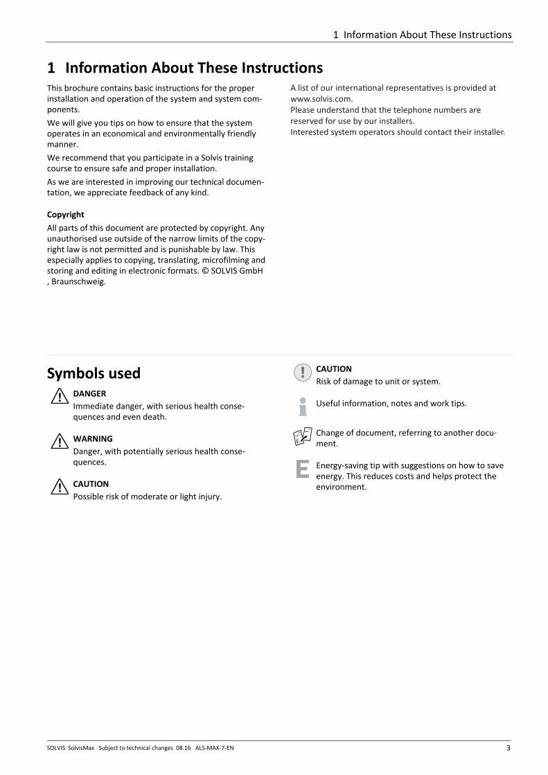
1 Information About These Instructions This brochure contains basic instructions for the proper installation and operation of the system and system com-ponents. We will give you tips on how to ensure that the system operates in an economical and environmentally friendly manner. We recommend that you participate in a Solvis training course to ensure safe and proper installation. As we are interested in improving our technical documen-tation, we appreciate feedback of any kind. Copyright All parts of this document are protected by copyright. Any unauthorised use outside of the narrow limits of the copy-right law is not permitted and is punishable by law. This especially applies to copying, translating, microfilming and storing and editing in electronic formats. © SOLVIS GmbH, Braunschweig.
A list of our interna�onal representa�ves is provided at www.solvis.com.Please understand that the telephone numbers are reserved for use by our installers.Interested system operators should contact their installer.
Symbols used DANGER Immediate danger, with serious health conse-quences and even death.
WARNING Danger, with potentially serious health conse-quences.
CAUTION Possible risk of moderate or light injury.
CAUTIONRisk of damage to unit or system.
Useful information, notes and work tips.
Change of document, referring to another docu-ment.
Energy-saving tip with suggestions on how to save energy. This reduces costs and helps protect the environment.

2 Gas, Öl, Fernwärme (District Heating), Pellet, Third-Party Boiler
4 SolvisMax Subject to technical changes 08.16 ALS-MAX-7-EN SOLVIS
2 Gas, Öl, Fernwärme (District Heating), Pellet, Third-Party Boiler 2.1 SolvisMax Gas and Öl 2.1.1 Basic equipment
H VL
H RL
BD
S8
A1
TWZ TWKTWW
S11
SV
S1
S4
SolvisMax Gas/Öl
S3
S9
STB
A12A13A14O 1
FA
SolvisControl
*
**
S10
S17
AG-xx
VS5
SP2
SÜS-Max
SOL-SKV
SV
P
SV-SOL6 bar
S7
I3
S6
SP1T
W
S18
S2
WWS
Fig. 1: SolvisMax Gas / SolvisMax Öl basic version with three mixed heating circuits – Part 1
* Only applies to SÖ, ** Only applies to SX Equipment • SolvisControl 2 system controller • Drinking water heating • Two mixed heating circuits • Solar circuit with one collector (field) • Oil or gas condensing system • An additional temperature-limited or mixed heating
circuit Modules: BD Lightning protection boxHKS-G Heating circuit station, mixed AG-xx Solar expansion vessel WWS Hot water station SG-H Heating circuit safety group SÜS-MAX Solar heat transferstation VTL-3 Distributor bar, 3-way
Abbreviations LA Air separatorAG Expansion vesselSAS Sludge separator SV Safety valveSOL-SKV Solar cap valveSV-SOL Solar safety valve TWK Drinking water network, cold connectionTWW Drinking water network, hot connectionTWZ Drinking water network, circulation connection
V Adjusting valveHK1-3 Heating circuit 1 to 3 FA Automatic firing system H-RL Heating returnH-VL Heating flowSTB Safety temperature limiter

2 Gas, Öl, Fernwärme (District Heating), Pellet, Third-Party Boiler
SOLVIS SolvisMax Subject to technical changes 08.16 ALS-MAX-7-EN 5
LA
SASH RL
H VL
SG-H
P
AG
3 bar
VTL-3
HKS-G
HK2
T TS13
A4A10
A11HKS-G
HK1
T TS12
A3
A9
A8MM
HKS-G
HK3
T TS16
A5A6
A7M
Fig. 2: SolvisMax Gas / SolvisMax Öl basic version with three mixed heating circuits – Part 2
This diagram is not a substitute for detailed technical planning. To ensure the correct function of the system, our installation, operating and maintenance instructions must be followed. When connecting a third-party boiler, do not rely solely on the information provided – consult the manufacturer of the boiler.
We reserve all copyright and protection rights for this drawing. This drawing may only be duplicated or made accessible to third parties with our express written permission. SOLVIS GmbH

2 Gas, Öl, Fernwärme (District Heating), Pellet, Third-Party Boiler
6 SolvisMax Subject to technical changes 08.16 ALS-MAX-7-EN SOLVIS
2.1.2 East/west roof
H VL
H RL
BD
S16
WOBD
S8
A6 A7
T
W
S18
S2
WWS
A1
TWZ TWKTWW
S11
SV
S1
S4
SolvisMax Gas/Öl
S3
S9
STB
A12A13A14
O 1FA
SolvisControl
,9;*,9;
**
S10
S17
VS5
SP2
SÜS Max
SV
SV-SOL 6 bar
S7
I3
S6
SP1 AG xx
SOL-SKV
P
Fig. 3: SolvisMax Gas / SolvisMax Öl with east-west roof, two mixed heating circuits – Part 1
* Only applies to SÖ, ** Only applies to SX Equipment • SolvisControl 2 system controller • Drinking water heating • Two mixed heating circuits • Solar circuit with one collector (field) • Oil or gas condensing system • Additional collector(field) on the opposite half of the
roof (east-west roof) Modules: BD Lightning protection boxHKS-G Heating circuit station, mixed AG-xx Solar expansion vessel WWS Hot water station SG-H Heating circuit safety group SÜS-MAX Solar heat transferstation VTL-3 Distributor bar, 3-way
Abbreviations LA Air separatorAG Expansion vesselSAS Sludge separator SV Safety valveSOL-SKV Solar cap valveSV-SOL Solar safety valve TWK Drinking water network, cold connectionTWW Drinking water network, hot connectionTWZ Drinking water network, circulation connection
V Adjusting valveHK1-3 Heating circuit 1 to 3 FA Automatic firing system H-RL Heating returnH-VL Heating flowSTB Safety temperature limiter O Collector (field) on the east roof W Collector (field) on the west roof

2 Gas, Öl, Fernwärme (District Heating), Pellet, Third-Party Boiler
SOLVIS SolvisMax Subject to technical changes 08.16 ALS-MAX-7-EN 7
H VL
H RL
LA
SAS
SG H
P
AG
3 bar
VTL 2
T
HKS G
HK1
T
S12
A3A8
A9 HKS G
HK2
T T
S13
A4
A11
A10
Fig. 4: SolvisMax Gas / SolvisMax Öl with an east-west roof, two mixed heating circuits – Part 2
This diagram is not a substitute for detailed technical planning. To ensure the correct function of the system, our installation, operating and maintenance instructions must be followed. When connecting a third-party boiler, do not rely solely on the information provided – consult the manufacturer of the boiler.
We reserve all copyright and protection rights for this drawing. This drawing may only be duplicated or made accessible to third parties with our express written permission. SOLVIS GmbH

2 Gas, Öl, Fernwärme (District Heating), Pellet, Third-Party Boiler
8 SolvisMax Subject to technical changes 08.16 ALS-MAX-7-EN SOLVIS
2.1.3 Solid fuel boiler
H/K RL
K RL
H/K VL
BD
S8
S17
AG-xx
VS5
SP2
SÜS-Max
SOL-SKV
SV
P
SV-SOL6 bar
S7
I3
S6
SP1
A1
TWZ TWKTWW
S11
SV
S1
S4
SolvisMax Gas/Öl
S3
S9
STB
A12A13A14O 1
FA
SolvisControl
*
**
S10
T
W
S18
S2
WWS
Fig. 5: SolvisMax Gas / SolvisMax Öl with a solid fuel boiler, two mixed heating circuits – Part 1
* Only applies to SÖ, ** Only applies to SX Equipment • SolvisControl 2 system controller • Drinking water heating • Two mixed heating circuits • Solar circuit with one collector (field) • Oil or gas condensing system • additional solid fuel boiler Modules: BD Lightning protection boxHKS-G Heating circuit station, mixed AG-xx Solar expansion vessel WWS Hot water station SG-H Heating circuit safety group SÜS-MAX Solar heat transferstation VTL-3 Distributor bar, 3-way PLAS Buffer charging station
Abbreviations LA Air separatorAG Expansion vesselSAS Sludge separator SV Safety valveSOL-SKV Solar cap valveSV-SOL Solar safety valve TWK Drinking water network, cold connectionTWW Drinking water network, hot connectionTWZ Drinking water network, circulation connection
V Adjusting valveFA Automatic firing system HK1-3 Heating circuit 1 to 3 H-RL Heating returnH/K-VL Heating and boiler flow K-RL Boiler returnSTB Safety temperature limiter FBK Solid fuel boilerTAS Thermal discharge safety device

2 Gas, Öl, Fernwärme (District Heating), Pellet, Third-Party Boiler
SOLVIS SolvisMax Subject to technical changes 08.16 ALS-MAX-7-EN 9
LA
SASH/K RL
H/K VL
K RL
T
PLAS
T
T
20mbar
50°C
A7
TWK
FBK
3 bar
TASS16
SG-H
P
AG
3 bar
VTL-2
T
HKS-G
HK1
TS12
A3A8
A9 HKS-G
HK2
T TS13
A4
A11
A10
Fig. 6: SolvisMax Gas / SolvisMax Öl with a solid fuel boiler, two mixed heating circuits – Part 2
This diagram is not a substitute for detailed technical planning. To ensure the correct function of the system, our installation, operating and maintenance instructions must be followed. When connecting a third-party boiler, do not rely solely on the information provided – consult the manufacturer of the boiler.
We reserve all copyright and protection rights for this drawing. This drawing may only be duplicated or made accessible to third parties with our express written permission. SOLVIS GmbH

2 Gas, Öl, Fernwärme (District Heating), Pellet, Third-Party Boiler
10 SolvisMax Subject to technical changes 08.16 ALS-MAX-7-EN SOLVIS
2.1.4 Swimming pool
H VL
H RL
BD
S8
A1
TWZ TWKTWW
S11
SV
S1
S4
SolvisMax Gas/Öl
S3
S9
STB
A12A13A14O 1
FA
SolvisControl
*
**
S10
S17
AG-xx
VS5
SP2
SÜS-Max
SOL-SKV
SV
P
SV-SOL6 bar
S7
I3
S6
SP1T
W
S18
S2
WWS
Fig. 7: SolvisMax Gas / SolvisMax Öl with swimming pool heating and two mixed heating circuits – Part 1
* Only applies to SÖ, ** Only applies to SX Equipment • SolvisControl 2 system controller • Drinking water heating • Two mixed heating circuits • Solar circuit with one collector (field) • Oil or gas condensing system • Solar swimming pool heating Modules: BD Lightning protection boxHKS-G Heating circuit station, mixed AG-xx Solar expansion vessel WWS Hot water station SG-H Heating circuit safety group SÜS-MAX Solar heat transferstation VTL-2 Distributor bar, 2-way RF Pool sensor BE-SC-2-O-SEN
Abbreviations LA Air separatorAG Expansion vesselSAS Sludge separator SV Safety valveSOL-SKV Solar cap valveSV-SOL Solar safety valve TWK Drinking water network, cold connectionTWW Drinking water network, hot connectionTWZ Drinking water network, circulation connection
V Adjusting valveHK1-2 Heating circuit 1 to 2 FA Automatic firing system H-RL Heating returnH-VL Heating flowSTB Safety temperature limiter Pool Swimming poolR3 Connection for room sensor 3 SC2 SolvisControl 2

2 Gas, Öl, Fernwärme (District Heating), Pellet, Third-Party Boiler
SOLVIS SolvisMax Subject to technical changes 08.16 ALS-MAX-7-EN 11
H RL
H VLLA
SAS
S16SC2
R3
T
A5
V
V
Pool
T
RF1)
A7
A6
SG-H
P
AG
3 bar
VTL-2
T
HKS-G
HK1
TS12
A3A8
A9 HKS-G
HK2
T TS13
A4
A11
A10
Fig. 8: SolvisMax Gas / SolvisMax Öl with swimming pool heating and two mixed heating circuits – Part 2
This diagram is not a substitute for detailed technical planning. To ensure the correct function of the system, our installation, operating and maintenance instructions must be followed. When connecting a third-party boiler, do not rely solely on the information provided – consult the manufacturer of the boiler.
We reserve all copyright and protection rights for this drawing. This drawing may only be duplicated or made accessible to third parties with our express written permission. SOLVIS GmbH

2 Gas, Öl, Fernwärme (District Heating), Pellet, Third-Party Boiler
12 SolvisMax Subject to technical changes 08.16 ALS-MAX-7-EN SOLVIS
2.1.5 Additional storage tank
BD
S8
SR 10H VL
SR 11SR 1
SR 12
T
W
S18
S2
WWS
A1
TWZ TWKTWW
S11
SV
S17
AG-xx
VS5
SP2
SÜS-Max
SOL-SKV
SV
P
SV-SOL6 bar
S7
I3
S6
SP1
S1
S4
SolvisMax Gas/Öl
S3
S9
STB
A12A13A14O 1
FA
SolvisControl
**
*
S10
Fig. 9: SolvisMax Gas/Öl, 2 storage tanks with a solid fuel boiler, two mixed heating circuits – Part 1
* Only applies to SÖ, ** Only applies to SX Equipment • SolvisControl 2 system controller • Drinking water heating • Two mixed heating circuits • Solar circuit with one collector (field) • Oil or gas condensing system • additional solid fuel boiler • additional storage (SolvisStrato) Modules: BD Lightning protection boxHKS-G Heating circuit station, mixed AG-xx Solar expansion vessel WWS Hot water station SG-H Heating circuit safety group SÜS-MAX Solar heat transferstation VTL-3 Distributor bar, 3-way PLAS Buffer charging station
Abbreviations LA Air separatorAG Expansion vesselSAS Sludge separator SV Safety valveSOL-SKV Solar cap valveSV-SOL Solar safety valve TWK Drinking water network, cold connectionTWW Drinking water network, hot connectionTWZ Drinking water network, circulation connection
V Adjusting valveFA Automatic firing system HK1-3 Heating circuit 1 to 3 H-VL Heating flowSR xx Connection to SolvisStrato STB Safety temperature limiter FBK Solid fuel boilerTAS Thermal discharge safety device

2 Gas, Öl, Fernwärme (District Heating), Pellet, Third-Party Boiler
SOLVIS SolvisMax Subject to technical changes 08.16 ALS-MAX-7-EN 13
SolvisStrato
2
4
6
8
10
12
1
3
5
7
9
11
LA
SAS
SR 10H VLSR 11SR 1SR 12
TWK
FBK
3 bar
TASS16
T
PLAS
T
T
20mbar
50°C
A7
SG-H
P
AG
3 bar
VTL-2
T
HKS-G
HK1
TS12
A3A8
A9 HKS-G
HK2
T TS13
A4
A11
A10
Fig. 10: SolvisMax Gas/Öl, two storage tanks with a solid fuel boiler, two mixed heating circuits – Part 2
This diagram is not a substitute for detailed technical planning. To ensure the correct function of the system, our installation, operating and maintenance instructions must be followed. When connecting a third-party boiler, do not rely solely on the information provided – consult the manufacturer of the boiler.
We reserve all copyright and protection rights for this drawing. This drawing may only be duplicated or made accessible to third parties with our express written permission. SOLVIS GmbH

2 Gas, Öl, Fernwärme (District Heating), Pellet, Third-Party Boiler
14 SolvisMax Subject to technical changes 08.16 ALS-MAX-7-EN SOLVIS
2.2 SolvisMax Fernwärme (with district heating)
BD
S8
A1
TWZ TWKTWW
S11
SV
S17
AG-xx
VS5
SP2
SÜS-Max
SOL-SKV
SV
P
SV-SOL6 bar
S7
I3
S6
SP1T
W
S18
S2
WWS
H/K VL
H/K RL
K RL
S1
S4
SolvisMax Fernwärme
S3
S9
SolvisControl
S10
A12S14
MmTW
FW RL
FW VL
T
T
P
WhP
P
Fig. 11: SolvisMax Fernwärme (with district heating) with a solid fuel boiler, two mixed heating circuits – Part 1
Equipment • SolvisControl 2 system controller • Drinking water heating • Two mixed heating circuits • Solar circuit with one collector (field) • Building control station for district heating • additional solid fuel boiler Modules: BD Lightning protection boxHKS-G Heating circuit station, mixed AG-xx Solar expansion vessel WWS Hot water station SG-H Heating circuit safety group SÜS-MAX Solar heat transferstation VTL-3 Distributor bar, 3-way PLAS Buffer charging station
Abbreviations LA Air separatorAG Expansion vesselSAS Sludge separator SV Safety valveSOL-SKV Solar cap valveSV-SOL Solar safety valve TWK Drinking water network, cold connectionTWW Drinking water network, hot connectionTWZ Drinking water network, circulation connection
V Adjusting valveHK1-3 Heating circuit 1 to 3 FW-RL District heating return FW-VL District heating flow H/K-VL Heating and boiler return H/K-VL Heating and boiler flow K-RL Boiler returnmTW Mechanical temperature controller FBK Solid fuel boilerTAS Thermal discharge safety device

2 Gas, Öl, Fernwärme (District Heating), Pellet, Third-Party Boiler
SOLVIS SolvisMax Subject to technical changes 08.16 ALS-MAX-7-EN 15
LA
SASH/K RL
H/K VL
K RL
T
PLAS
T
T
20mbar
50°C
A7
TWK
FBK
3 bar
TASS16
SG-H
P
AG
3 bar
VTL-2
T
HKS-G
HK1
TS12
A3A8
A9 HKS-G
HK2
T TS13
A4
A11
A10
Fig. 12: SolvisMax Fernwärme (with district heating) with a solid fuel boiler, two mixed heating circuits – Part 2
This diagram is not a substitute for detailed technical planning. To ensure the correct function of the system, our installation, operating and maintenance instructions must be followed. When connecting a third-party boiler, do not rely solely on the information provided – consult the manufacturer of the boiler.
We reserve all copyright and protection rights for this drawing. This drawing may only be duplicated or made accessible to third parties with our express written permission. SOLVIS GmbH

2 Gas, Öl, Fernwärme (District Heating), Pellet, Third-Party Boiler
16 SolvisMax Subject to technical changes 08.16 ALS-MAX-7-EN SOLVIS
2.3 SolvisMax Solo with SolvisLino 4 2.3.1 Basic equipment
H/K RL
H/K VL
BD
S8
T
W
S18
S2
WWS
A1
TWZ TWKTWW
S11
SV
S17
AG xx
VS5
SP2
SÜS Max
SOL-SKV
SV
P
SV-SOL6 bar
S7
I3
S6
SP1
S1
S4
SolvisMax Solo
S3
S9
SolvisControl
S10
Fig. 13: SolvisMax Solo basic version with SolvisLino 4 and three mixed heating circuits – Part 1
Equipment • SolvisControl 2 system controller • Drinking water heating • Two mixed heating circuits • Solar circuit with one collector (field) • Adjacent SolvisLino pellet boiler • Buffer load circuit without return increase with speed-
controlled load pump • An additional temperature-limited or mixed heating
circuit Modules: BD Lightning protection boxHKS-G Heating circuit station, mixed AG-xx Solar expansion vessel WWS Hot water station SG-H Heating circuit safety group SÜS-MAX Solar heat transferstation VTL-3 Distributor bar, 3-way PLAS Buffer charging station
Abbreviations LA Air separatorAG Expansion vesselSAS Sludge separator SV Safety valveSOL-SKV Solar cap valveSV-SOL Solar safety valve TWK Drinking water network, cold connectionTWW Drinking water network, hot connectionTWZ Drinking water network, circulation connection
V Adjusting valveHK1-3 Heating circuit 1 to 3 H/K-VL Heating and boiler return H/K-VL Heating and boiler flow

2 Gas, Öl, Fernwärme (District Heating), Pellet, Third-Party Boiler
SOLVIS SolvisMax Subject to technical changes 08.16 ALS-MAX-7-EN 17
LA
SASH/K RL
H/K VL
SG H
P
AG
3 bar
VTL 3
HKS G
HK2
T T
S13
A4
A10
A11HKS G
HK1
T T
S12
A3
A9
A8MM
HKS G
HK3
T T
S16
A5
A6
A7MT
PLASUGM
T
20mbar
SolvisLino 4
3 bar
A13
S14O 1
LP
Fig. 14: SolvisMax Solo basic version with SolvisLino 4 and three mixed heating circuits – Part 2
This diagram is not a substitute for detailed technical planning. To ensure the correct function of the system, our installation, operating and maintenance instructions must be followed. When connecting a third-party boiler, do not rely solely on the information provided – consult the manufacturer of the boiler.
We reserve all copyright and protection rights for this drawing. This drawing may only be duplicated or made accessible to third parties with our express written permission. SOLVIS GmbH
Requirement for operating SolvisLino 4 without return increase: • Properly functioning speed control of the buffer
load pump by SolvisControl 2 in software version MA201 or later
• Using the PLAS (unmixed) buffer charging station• Connection of SolvisLino according to connection
diagram.

2 Gas, Öl, Fernwärme (District Heating), Pellet, Third-Party Boiler
18 SolvisMax Subject to technical changes 08.16 ALS-MAX-7-EN SOLVIS
2.3.2 East/west roof
BD
S16
WOBD
S8
A6 A7
H/K RL
H/K VL
T
W
S18
S2
WWS
A1
TWZ TWKTWW
S11
SV
S1
S4
SolvisMax Solo
S3
S9
SolvisControl
S10
S17
VS5
SP2
SÜS Max
SV
SV-SOL 6 bar
S7
I3
S6
SP1
Ost West Dach
AG xx
SOL-SKV
P
Fig. 15: SolvisMax Solo with an east-west roof, SolvisLino 4 and two mixed heating circuits – Part 1
Equipment • SolvisControl 2 system controller • Drinking water heating • Two mixed heating circuits • Solar circuit with one collector (field) • Adjacent SolvisLino pellet boiler • Buffer load circuit without return increase with speed-
controlled load pump • Additional collector(field) on the opposite half of the
roof (east-west roof) Modules: BD Lightning protection boxHKS-G Heating circuit station, mixed AG-xx Solar expansion vessel WWS Hot water station SG-H Heating circuit safety group SÜS-MAX Solar heat transferstation VTL-3 Distributor bar, 3-way PLAS Buffer charging station
Abbreviations LA Air separatorAG Expansion vesselSAS Sludge separator SV Safety valveSOL-SKV Solar cap valveSV-SOL Solar safety valve TWK Drinking water network, cold connectionTWW Drinking water network, hot connectionTWZ Drinking water network, circulation connection
V Adjusting valveHK1-2 Heating circuit 1 to 2 H/K-VL Heating and boiler return H/K-VL Heating and boiler flow O Collector (field) on the east roof W Collector (field) on the west roof

2 Gas, Öl, Fernwärme (District Heating), Pellet, Third-Party Boiler
SOLVIS SolvisMax Subject to technical changes 08.16 ALS-MAX-7-EN 19
LA
SASH/K RL
H/K VL
SG H
P
AG
3 bar
VTL 3
HKS G
HK2
T T
S13
A4A10
A11HKS G
HK1
T T
S12
A3
A9
A8MM
T
PLASUGM
T
20mbar
SolvisLino 4
3 bar
A13
S14O 1
LP
Fig. 16: SolvisMax Solo with an east-west roof, SolvisLino 4 and two mixed heating circuits – Part 2
This diagram is not a substitute for detailed technical planning. To ensure the correct function of the system, our installation, operating and maintenance instructions must be followed. When connecting a third-party boiler, do not rely solely on the information provided – consult the manufacturer of the boiler.
We reserve all copyright and protection rights for this drawing. This drawing may only be duplicated or made accessible to third parties with our express written permission. SOLVIS GmbH
Requirement for operating SolvisLino 4 without return increase: • Properly functioning speed control of the buffer
load pump by SolvisControl 2 in software version MA201 or later
• Using the PLAS (unmixed) buffer charging station• Connection of SolvisLino according to connection
diagram.

2 Gas, Öl, Fernwärme (District Heating), Pellet, Third-Party Boiler
20 SolvisMax Subject to technical changes 08.16 ALS-MAX-7-EN SOLVIS
2.3.3 Solid fuel boiler
H/K RL
H/K VL
K RL
BD
S8
T
W
S18
S2
WWS
A1
TWZ TWKTWW
S11
SV
S17
AG xx
VS5
SP2
SÜS Max
SOL-SKV
SV
P
SV-SOL6 bar
S7
I3
S6
SP1
S1
S4
SolvisMax Solo
S3
S9
SolvisControl
S10
Fig. 17: SolvisMax Solo with SolvisLino 4, a solid fuel boiler and two mixed heating circuits – Part 1
Equipment • SolvisControl 2 system controller • Drinking water heating • Two mixed heating circuits • Solar circuit with one collector (field) • Adjacent SolvisLino pellet boiler • Buffer load circuit without return increase with speed-
controlled load pump • additional solid fuel boiler Modules: BD Lightning protection boxHKS-G Heating circuit station, mixed AG-xx Solar expansion vessel WWS Hot water station SG-H Heating circuit safety group SÜS-MAX Solar heat transferstation VTL-3 Distributor bar, 3-way PLAS Buffer charging station
Abbreviations LA Air separatorAG Expansion vesselSAS Sludge separator SV Safety valveSOL-SKV Solar cap valveSV-SOL Solar safety valve TWK Drinking water network, cold connectionTWW Drinking water network, hot connectionTWZ Drinking water network, circulation connection
V Adjusting valveHK1-2 Heating circuit 1 to 2 H/K-VL Heating and boiler return H/K-VL Heating and boiler flow K-RL Boiler returnFBK Solid fuel boilerTAS Thermal discharge safety device

2 Gas, Öl, Fernwärme (District Heating), Pellet, Third-Party Boiler
SOLVIS SolvisMax Subject to technical changes 08.16 ALS-MAX-7-EN 21
LA
SAS
H/K VL
H/K RL
K RL
T
PLAS
T
T
20mbar
50°C
A7
TWK
FBK
3 bar
TASS16
SG H
P
AG
3 bar
VTL 3
HKS G
HK2
T T
S13
A4A10
A11HKS G
HK1
T T
S12
A3
A9
A8MM
T
PLASUGM
T
20mbar
SolvisLino 4
3 bar
A13
S14O 1
LP
Fig. 18: SolvisMax Solo with SolvisLino 4, a solid fuel boiler and two mixed heating circuits – Part 2
This diagram is not a substitute for detailed technical planning. To ensure the correct function of the system, our installation, operating and maintenance instructions must be followed. When connecting a third-party boiler, do not rely solely on the information provided – consult the manufacturer of the boiler.
We reserve all copyright and protection rights for this drawing. This drawing may only be duplicated or made accessible to third parties with our express written permission. SOLVIS GmbH
Requirement for operating SolvisLino 4 without return increase: • Properly functioning speed control of the buffer
load pump by SolvisControl 2 in software version MA201 or later
• Using the PLAS (unmixed) buffer charging station• Connection of SolvisLino according to connection
diagram.

2 Gas, Öl, Fernwärme (District Heating), Pellet, Third-Party Boiler
22 SolvisMax Subject to technical changes 08.16 ALS-MAX-7-EN SOLVIS
2.3.4 Additional storage tank
BD
S8
SR 10
H VL
SR 11
SR 1
SR 12
T
W
S18
S2
WWS
A1
TWZ TWKTWW
S11
SV
S17
AG xx
VS5
SP2
SÜS Max
SOL-SKV
SV
P
SV-SOL6 bar
S7
I3
S6
SP1
S1
S4
SolvisMax Solo
S3
S9
SolvisControl
S10
Fig. 19: SolvisMax Solo with SolvisLino 4, a second storage tank, a solid fuel boiler, two mixed heating circuits – Part 1
Equipment • SolvisControl 2 system controller • Drinking water heating • Two mixed heating circuits • Solar circuit with one collector (field) • Adjacent SolvisLino pellet boiler • additional solid fuel boiler • additional storage (SolvisStrato) Modules: BD Lightning protection boxHKS-G Heating circuit station, mixed AG-xx Solar expansion vessel WWS Hot water station SG-H Heating circuit safety group SÜS-MAX Solar heat transferstation VTL-3 Distributor bar, 3-way PLAS Buffer charging station
Abbreviations LA Air separatorAG Expansion vesselSAS Sludge separator SV Safety valveSOL-SKV Solar cap valveSV-SOL Solar safety valve TWK Drinking water network, cold connectionTWW Drinking water network, hot connectionTWZ Drinking water network, circulation connection
V Adjusting valveHK1-3 Heating circuit 1 to 3 H-VL Heating flowSR xx Connection to SolvisStrato FBK Solid fuel boilerTAS Thermal discharge safety device

2 Gas, Öl, Fernwärme (District Heating), Pellet, Third-Party Boiler
SOLVIS SolvisMax Subject to technical changes 08.16 ALS-MAX-7-EN 23
SolvisStrato
2
4
6
8
10
12
1
3
5
7
9
11
LA
SAS
SR 10H VLSR 1
SR 11SR 12
TWK
FBK
3 bar
TASS16
SG H
P
AG
3 bar
T
PLAST
T
20mbar
50°C
A7
VTL 2
T
HKS G
HK1
T
S12
A3A8
A9 HKS G
HK2
T T
S13
A4
A11
A10
T
PLAST
T
20mbar
45°C
SolvisLino 4
3 bar
A13
S14O 1
Fig. 20: SolvisMax Solo with SolvisLino 4, a second storage tank, a solid fuel boiler, two mixed heating circuits – Part 2
This diagram is not a substitute for detailed technical planning. To ensure the correct function of the system, our installation, operating and maintenance instructions must be followed. When connecting a third-party boiler, do not rely solely on the information provided – consult the manufacturer of the boiler.
We reserve all copyright and protection rights for this drawing. This drawing may only be duplicated or made accessible to third parties with our express written permission. SOLVIS GmbH

2 Gas, Öl, Fernwärme (District Heating), Pellet, Third-Party Boiler
24 SolvisMax Subject to technical changes 08.16 ALS-MAX-7-EN SOLVIS
2.4 SolvisMax Solo with third-party boiler 2.4.1 Basic equipment
H/K RL
H/K VL
BD
S8
T
W
S18
S2
WWS
A1
TWZ TWKTWW
S11
SV
S17
AG xx
VS5
SP2
SÜS Max
SOL-SKV
SV
P
SV-SOL6 bar
S7
I3
S6
SP1
S1
S4
SolvisMax Solo
S3
S9
SolvisControl
S10
Fig. 21: SolvisMax Solo basic version with third-party boiler and three mixed heating circuits – Part 1
Equipment • SolvisControl 2 system controller • Drinking water heating • Two mixed heating circuits • Solar circuit with one collector (field) • Adjacent customer-provided boiler (third-party boiler) • An additional temperature-limited or mixed heating
circuit Modules: BD Lightning protection boxHKS-G Heating circuit station, mixed AG-xx Solar expansion vessel WWS Hot water station SG-H Heating circuit safety group SÜS-MAX Solar heat transferstation VTL-3 Distributor bar, 3-way
Abbreviations LA Air separatorAG Expansion vesselSAS Sludge separator SV Safety valveSOL-SKV Solar cap valveSV-SOL Solar safety valve TWK Drinking water network, cold connectionTWW Drinking water network, hot connectionTWZ Drinking water network, circulation connection
V Adjusting valveHK1-3 Heating circuit 1 to 3 H/K-VL Heating and boiler return H/K-VL Heating and boiler flow FA Automatic firing system FK Third-party boiler FSB Spring-loaded gravitational force brake

2 Gas, Öl, Fernwärme (District Heating), Pellet, Third-Party Boiler
SOLVIS SolvisMax Subject to technical changes 08.16 ALS-MAX-7-EN 25
LA
SASH/K RL
H/K VL
SG H
P
AG
3 bar
FK
4-36l/min
FSB
TT
3 bar
FA
O 1
S14
VA13
A12 A14
VTL 3
HKS G
HK2
T T
S13
A4
A10
A11HKS G
HK1
T T
S12
A3
A9
A8MM
HKS G
HK3
T T
S16
A5
A6
A7M
Fig. 22: SolvisMax Solo basic version with third-party boiler and three mixed heating circuits – Part 2
This diagram is not a substitute for detailed technical planning. To ensure the correct function of the system, our installation, operating and maintenance instructions must be followed. When connecting a third-party boiler, do not rely solely on the information provided – consult the manufacturer of the boiler.
We reserve all copyright and protection rights for this drawing. This drawing may only be duplicated or made accessible to third parties with our express written permission. SOLVIS GmbH

2 Gas, Öl, Fernwärme (District Heating), Pellet, Third-Party Boiler
26 SolvisMax Subject to technical changes 08.16 ALS-MAX-7-EN SOLVIS
2.4.2 East/west roof
BD
S16
WOBD
S8
A6 A7
H/K RL
H/K VL
T
W
S18
S2
WWS
A1
TWZ TWKTWW
S11
SV
S1
S4
SolvisMax Solo
S3
S9
SolvisControl
S10
S17
VS5
SP2
SÜS Max
SV
SV-SOL 6 bar
S7
I3
S6
SP1
Ost West Dach
AG xx
SOL-SKV
P
Fig. 23: SolvisMax Solo with third-party boiler, east-west roof, two mixed heating circuits – Part 1
Equipment • SolvisControl 2 system controller • Drinking water heating • Two mixed heating circuits • Solar circuit with one collector (field) • Adjacent customer-provided boiler (third-party boiler) • Additional collector(field) on the opposite half of the
roof (east-west roof) Modules: BD Lightning protection boxHKS-G Heating circuit station, mixed AG-xx Solar expansion vessel WWS Hot water station SG-H Heating circuit safety group SÜS-MAX Solar heat transferstation VTL-3 Distributor bar, 3-way
Abbreviations LA Air separatorAG Expansion vesselSAS Sludge separator SV Safety valveSOL-SKV Solar cap valveSV-SOL Solar safety valve TWK Drinking water network, cold connectionTWW Drinking water network, hot connectionTWZ Drinking water network, circulation connection
V Adjusting valveHK1-3 Heating circuit 1 to 3 H/K-VL Heating and boiler return H/K-VL Heating and boiler flow FA Automatic firing system FK Third-party boiler FSB Spring-loaded gravitational force brakeO Collector (field) on the east roof W Collector (field) on the west roof

2 Gas, Öl, Fernwärme (District Heating), Pellet, Third-Party Boiler
SOLVIS SolvisMax Subject to technical changes 08.16 ALS-MAX-7-EN 27
LA
SASH/K RL
H/K VL
FK
4-36l/min
FSB
TT
3 bar
FA
O 1
S14
VA13
A12 A14
SG H
P
AG
3 bar
VTL 2
T
HKS G
HK1
T
S12
A3A8
A9 HKS G
HK2
T T
S13
A4
A11
A10
Fig. 24: SolvisMax Solo with third-party boiler, east-west roof, two mixed heating circuits – Part 2
This diagram is not a substitute for detailed technical planning. To ensure the correct function of the system, our installation, operating and maintenance instructions must be followed. When connecting a third-party boiler, do not rely solely on the information provided – consult the manufacturer of the boiler.
We reserve all copyright and protection rights for this drawing. This drawing may only be duplicated or made accessible to third parties with our express written permission. SOLVIS GmbH

2 Gas, Öl, Fernwärme (District Heating), Pellet, Third-Party Boiler
28 SolvisMax Subject to technical changes 08.16 ALS-MAX-7-EN SOLVIS
2.4.3 Solid fuel boiler
H/K RL
H/K VL
K RL
BD
S8
T
W
S18
S2
WWS
A1
TWZ TWKTWW
S11
SV
S17
AG xx
VS5
SP2
SÜS Max
SOL-SKV
SV
P
SV-SOL6 bar
S7
I3
S6
SP1
S1
S4
SolvisMax Solo
S3
S9
SolvisControl
S10
Fig. 25: SolvisMax Solo with third-party boiler, solid fuel boiler, two mixed heating circuits – Part 1
Equipment • SolvisControl 2 system controller • Drinking water heating • Two mixed heating circuits • Solar circuit with one collector (field) • Adjacent customer-provided boiler (third-party boiler) • additional solid fuel boiler Modules: BD Lightning protection boxHKS-G Heating circuit station, mixed AG-xx Solar expansion vessel WWS Hot water station SG-H Heating circuit safety group SÜS-MAX Solar heat transferstation VTL-3 Distributor bar, 3-way PLAS Buffer charging station
Abbreviations LA Air separatorAG Expansion vesselSAS Sludge separator SV Safety valveSOL-SKV Solar cap valveSV-SOL Solar safety valve TWK Drinking water network, cold connectionTWW Drinking water network, hot connectionTWZ Drinking water network, circulation connection
V Adjusting valveHK1-3 Heating circuit 1 to 3 H/K-VL Heating and boiler return H/K-VL Heating and boiler flow K-RL Boiler returnFA Automatic firing system FK Third-party boiler FSB Spring-loaded gravitational force brakeFBK Solid fuel boilerTAS Thermal discharge safety device

2 Gas, Öl, Fernwärme (District Heating), Pellet, Third-Party Boiler
SOLVIS SolvisMax Subject to technical changes 08.16 ALS-MAX-7-EN 29
LA
SASH/K RL
H/K VL
K RL
T
PLAS
T
T
20mbar
50°C
A7
TWK
FBK
3 bar
TASS16
FK
4-36l/min
FSB
TT
3 bar
FA
O 1
S14
VA13
A12 A14
SG H
P
AG
3 bar
VTL 2
T
HKS G
HK1
T
S12
A3A8
A9 HKS G
HK2
T T
S13
A4
A11
A10
Fig. 26: SolvisMax Solo with third-party boiler, solid fuel boiler, two mixed heating circuits – Part 2
This diagram is not a substitute for detailed technical planning. To ensure the correct function of the system, our installation, operating and maintenance instructions must be followed. When connecting a third-party boiler, do not rely solely on the information provided – consult the manufacturer of the boiler.
We reserve all copyright and protection rights for this drawing. This drawing may only be duplicated or made accessible to third parties with our express written permission. SOLVIS GmbH

2 Gas, Öl, Fernwärme (District Heating), Pellet, Third-Party Boiler
30 SolvisMax Subject to technical changes 08.16 ALS-MAX-7-EN SOLVIS
2.5 Connection Diagram 2.5.1 Connection table (system status) SolvisMax Gas, Öl, FW and Solo Sensors (temperature sensors and volume flow encoders) Actuators (pumps, signals and control valves) Inputs
Designation (sensor) Outputs
Designation no. Option no. OptionS1 All Sto. tank, top A1 All Circulation pump S2 All Hot water A2 All (Unused) S3 All Sto. tank reference A3 All Pump for heating circuit 1 S4 All Heating buffer, upper A4 All Pump for heating circuit 2 S5 All Solar flow 2 A5 All Pump for heating circuit 3
S6 All Solar return 2 A6 East-west roof Valve 1 Solid fuel boiler (FBK) (Unused) HC 3 Heating circuit 3 mixer open
S7 All Solar flow 1 A7 East-west roof Valve 2 Solid fuel boiler (FBK) Load pump HC 3 Heating circuit 3 mixer closed
S8 All Collector A8 All Heating circuit 1 mixer (open)S9 All Heating buffer, lower A9 All Heating circuit 1 mixer (closed)S10 All Outdoor temperature A10 All Heating circuit 2 mixer (open)S11 All Circulation A11 All Heating circuit 2 mixer (closed)S12 All Flow for heating circuit 1 A12 All District heating valve3) / burner
S13 All Flow for heating circuit 2 A13 All LI-3/4 load pump or third-party boiler 1)/burner 2 2) / –––
S14 All LI-3/41) boiler/third-party boiler1)/district heating return3) / ––– A14 All District heating valve3) / burner 1) / interf.
supp.S15 All Cold water (optional) O-1 All Modulation4) (0 – 10 V) / –––2)
S16 East-west roof Collector 2
SP1 All PWM solar pump 1 Solid fuel boiler (FBK) Wood boiler Other Flow for heating circuit 3
S17 All Solar volume flow encoder SP2 All PWM solar pump 2 S18 All Water volume flow encoder W All PWM hot water pump I-1 All External burner requirement LP All PWM load pump LI-3/4 or third-party boiler I-2 All (Unused) I-3 All Solar pressure
R1 All Room control element for heating circuit 1 (optional)
R2 All Room control element for heating circuit 2 (optional)
R3 All Room control element for heating circuit 3 (optional)
ST1 All Jumper / mechanical safety temperature limiter (mSTL)2)
ST2 All Jumper * “All” = applies to “Normal”, “East-west roof”, “Solid fuel boiler” and “HC 3”. “Normal” = without option, “Solid fuel boiler” = additional solid fuel boiler or “HC 3” = additional mixed heating circuit 1) Only applies to SolvisMax Solo 2) Only applies to SolvisMax Öl 3) Only applies to SolvisMax Fernwärme (with district heating) 4) Burner requirement and modulation for SolvisLino 3

2 Gas, Öl, Fernwärme (District Heating), Pellet, Third-Party Boiler
SOLVIS SolvisMax Subject to technical changes 08.16 ALS-MAX-7-EN 31
2.5.2 Mains module
Prog.
ST1
N
M
M 6,3 A T 1,0 A
L´ N´ N L L N PE
A1
A2
A3
A4
A5
A6
A7
A8A9
A13
A10A11
ST2
A12S3 T2 T1 L PE
A1 N PE
A2 N PE
A3 N PE
A4 N PE
A5 N PE
A6 N PE
A7 N PE
A8 A9
N
PE
A13 N PE
A10 A11 N PE
S18 S17 S16 S15 S14 S13 S12 S11 S10
Solar 1/2 O1
LP
-R3+ -R2+ -R1+
-I3+ -I2+ -I1+ VCC
A14
WW
S9 S8 S7 S6 S5 S4 S3 S2 S1
n
ϑ
ϑ
ϑS8
ϑ
n
ϑ
ϑ
ϑ
S7
S6
S5
S14
S15
S16
S17
S18
ϑ
ϑR1
R2
ϑ
ϑ
S4ϑ
ϑ
ϑ
ϑ
S3
S1
S2 WWS
EP
S13
S12
S11
S10ϑ
ϑ
S
PENL 1
M A5
PENL 1
M A4
A8/9
M A10/11
PENL 1
M
PWM
PWM
PWM
A1
LNPE
N'L'
SX
01/A14
Al. SX
Al. SÖ
SÖ SX
A12
A13/14
SÖ
S9ϑ
ϑR3
pI 3
I 1
SolarLPWWS
PENL 1
M A3
PENL 1
M
M A6/7
NL PE
NL PE
Al. OW-D
Al. OW-D
Al. FBK
o. ASTB*
mSTB o.
Al. SL
Al. SÖ
PWMSolar
PENL
MA13 1
KKB LI3 SC 2 Al. SL-LI
KBB SC 2
ZR-Schni�stelle
Alarm
BR
KBB SÜS
KBB Netz 7 SC 2
Reset
RS232
BR
Fig. 27: SolvisControl 2 mains module for SolvisMax Gas, Öl, Fernwärme (with district heating) and Solo
* Exhaust safety temperature limiter (ESTL) only required in Switzerland AL FBK Solid fuel boiler alternative KBB-LI3-SC2 Burner cable for SolvisLino 3/4 AL OWD East-west roof alternative KBB SC-2 SolvisControl 2 sensor cable harness AL SL-LI Alternative: SolvisSolo with SolvisLino 3/4 KBB-SÜS Sensor cable harness for solar heat transfer stationAL SÖ Alternative connection for SolvisMax Öl mSTL Mechanical safety temperature limiter AL SX Alternative connection for SolvisMax Gas WWS Hot water stationESTL Exhaust safety temperature limiter ZR Central controller interface BR Jumper EP Expansion board, see Fig. 42, p. 44

3 Heating Pumps
32 SolvisMax Subject to technical changes 08.16 ALS-MAX-7-EN SOLVIS
3 Heating Pumps 3.1 SolvisMax Teo (brine/water)
BD
S8
H VLWW VL
WP RL
H RL
T
A2
S18
S2
WWS
*S16
A5
TWZ TWKTWW
S11
SV
S17
AG-xx
VS5
O 3
SÜS-Max
SOL-SKV
SV
P
SV-SOL6 bar
S7
S6
O 2
S1
S4o
SolvisMax Teo
S3
S4u
SolvisControl
S10
Fig. 28: SolvisMax Teo with SolvisTeo and two mixed heating circuits – Part 1
Equipment • SolvisControl 2 system controller • Drinking water heating • Two mixed heating circuits • Solar circuit with one collector (field) • Adjacent SolvisTeo brine/water heating pump Modules: BD Lightning protection boxHKS-G Heating circuit station, mixed AG-xx Solar expansion vessel WWS Hot water station SG-H Heating circuit safety group SÜS-MAX Solar heat transferstation VTL-2 Distributor bar, 2-way SOS-SW Brine station Heat exchanger (brine support, option) 1 From SolvisMax 2 To heating pump 3 From heat source 4 To collector
Abbreviations LA Air separatorAG Expansion vesselSAS Sludge separator SV Safety valveSOL-SKV Solar cap valveSV-SOL Solar safety valve TWK Drinking water network, cold connectionTWW Drinking water network, hot connectionTWZ Drinking water network, circulation connection
V Adjusting valveHK1-2 Heating circuit 1 to 2 S-RL Solar returnDW Brine pressure controller H-RL Heating returnH-VL Heating flowWP-RL Heating pump return WQ-RL Heat source return WQ-VL Heat source flow WW-VL Hot water flow

3 Heating Pumps
SOLVIS SolvisMax Subject to technical changes 08.16 ALS-MAX-7-EN 33
LA
S14 S15
WP RL
H RL
H VL
WQ VL WQ RL
WQ RLWQ VL
MA
B
ABA3.2
WW VL
SAS
10-40l/min
Solvis Teo
A12A3.3
MB
AAB
S9
*
O 1
SOS-SW
V
P
AG
DW(ST2)
I P
3 bar
SG-H
P
AG
3 bar
VTL-2
T
HKS-G
HK1
TS12
A3A8
A9 HKS-G
HK2
T TS13
A4
A11
A10
S-RL
1 2
34
Fig. 29: SolvisMax Teo with SolvisTeo and two mixed heating circuits – Part 2
* Brine support optional
This diagram is not a substitute for detailed technical planning. To ensure the correct function of the system, our installation, operating and maintenance instructions must be followed. When connecting a third-party boiler, do not rely solely on the information provided – consult the manufacturer of the boiler.
We reserve all copyright and protection rights for this drawing. This drawing may only be duplicated or made accessible to third parties with our express written permission. SOLVIS GmbH

3 Heating Pumps
34 SolvisMax Subject to technical changes 08.16 ALS-MAX-7-EN SOLVIS
3.2 SolvisMax Vaero (air/water)
BD
S8
H/K VL
H/K RL
WP RL
WP VL
SAS
SV
T
A2
S18
S2
WWS
S1
S4
SolvisMax Vaero
S3
S9
SolvisControl
S10
A5
TWZ TWKTWW
S11
SV
10-40l/min
Alarm
O 1
PLAS-WP
V
S17
AG-xx
VS5
O 3
SÜS-Max
SOL-SKV
SV
P
SV-SOL6 bar
S7
S6
O 2
Fig. 30: SolvisMax Vaero with SolvisVaero, third-party boiler and two mixed heating circuits – Part 1
Equipment • SolvisControl 2 system controller • Drinking water heating • Two mixed heating circuits • Solar circuit with one collector (field) • Adjacent SolvisVaero air/water heating pump • Adjacent customer-provided boiler (third-party boiler) Modules: BD Lightning protection boxHKS-G Heating circuit station, mixed AG-xx Solar expansion vessel WWS Hot water station SG-H Heating circuit safety group SÜS-MAX Solar heat transferstation VTL-2 Distributor bar, 2-way
Abbreviations LA Air separatorAG Expansion vesselSAS Sludge separator SV Safety valveSOL-SKV Solar cap valveSV-SOL Solar safety valve TWK Drinking water network, cold connectionTWW Drinking water network, hot connectionTWZ Drinking water network, circulation connection
V Adjusting valveHK1-2 Heating circuit 1 to 2 H/K-VL Heating and boiler return H/K-VL Heating and boiler flow WP-RL Heating pump return WP-VL Heating pump flow HE House infeedFA Automatic firing system FK Third-party boiler FSB Spring-loaded gravitational force brake

3 Heating Pumps
SOLVIS SolvisMax Subject to technical changes 08.16 ALS-MAX-7-EN 35
*A6V
*
FA
A63 bar
T T
FSB
FK
4-36l/min
FK*
H/K VL
H/K RL
WP RL
WP VL
LA
SAS
HE
WP-XX
A12 A14S14
S15
A13A6
S3/A12
I1
SG-H
P
AG
3 bar
VTL-2
T
HKS-G
HK1
TS12
A3A8
A9 HKS-G
HK2
T TS13
A4
A11
A10
Fig. 31: SolvisMax Vaero with SolvisVaero, third-party boiler and two mixed heating circuits – Part 2
* Customer-provided boiler optional (third-party boiler)
This diagram is not a substitute for detailed technical planning. To ensure the correct function of the system, our installation, operating and maintenance instructions must be followed. When connecting a third-party boiler, do not rely solely on the information provided – consult the manufacturer of the boiler.
We reserve all copyright and protection rights for this drawing. This drawing may only be duplicated or made accessible to third parties with our express written permission. SOLVIS GmbH

3 Heating Pumps
36 SolvisMax Subject to technical changes 08.16 ALS-MAX-7-EN SOLVIS
3.3 Connection Diagram 3.3.1 Connection table (system status) SolvisMax Teo, SolvisMax Vaero Sensors (temperature sensor and volume flow encoder) Actuators (pumps, signals and control valves)
Input no. Designation Output
no. Designation
S1 Sto. tank, top A1 (Unused)S2 Hot water A2 PWM hot water pump S3 Sto. tank reference A3 Pump for heating circuit 1
S4 [Upper heating buffer (S4o) and lower heating buffer (S4u)]* / upper heating buffer** A4 Pump for heating circuit 2
S5 Solar flow 2 A5 Circulation pumpS6 Solar return 2 A6 ––* / Heating cartridge requirement** S7 Solar flow 1 A7 (Unused)S8 Collector A8 Heating circuit 1 mixer (open) S9 Heating pump return* / lower heating buffer** A9 Heating circuit 1 mixer (closed)
S10 Outdoor temperature A10 Heating circuit 2 mixer (open) S11 Circulation A11 Heating circuit 2 mixer (closed) S12 Flow for heating circuit 1 A12 Compressor requirement S13 Flow for heating circuit 2 A13 ––* / Heating cartridge 2 requirement** S14 Brine flow* / heating pump return** A14 ––* / Interf. supp.**
S15 Brine return* / heating pump flow** O-1 Brine pump* / buffer charging station heating pump (PLAS-WP)**
S16 Solar return 1 O-2 PWM solar pump 1S17 Solar volume flow encoder O-3 PWM solar pump 2S18 Water volume flow encoder
S3/A12 Low/high press. add-on* / defrosting signal** I-1 Integrated heating pump controller (IWS) malfunction**I-2 Block time I-3 (Unused) R1 Room control element for heating circuit 1 (optional)R2 Room control element for heating circuit 2 (optional)ST1 Brine pressure controller* / jumper** ST2 Brine leak* / jumper**
* Only applies to SolvisMax Teo ** Only applies to SolvisMax Vaero

3 Heating Pumps
SOLVIS SolvisMax Subject to technical changes 08.16 ALS-MAX-7-EN 37
3.3.2 Mains module
Prog.
A
ST1
N
M
S Ö
M 12V
M 6,3 A T 1,0 A
L´ N´ N L L N PE
A1
A2
A3
A4
A5
A6
A7
A8A9
A13
A10A11
ST2
A12S3 T2 T1 L PE
A1 N PE
A2 N PE
A3 N PE
A4 N PE
A5 N PE
A6 N PE
A7 N PE
A8 A9 N PE
A13 N PEL 13 12
A10 A11 N PE
S18 S17 S16 S15 S14 S13 S12 S11 S10
-O3+ -O2+ -O1+
M S17 VCCDFG 1
-R3+ -R2+ -R1+
-I3+ -I2+ -I1+ VCC
A14
M S18 VCCDFG 2
S9 S8 S7 S6 S5 S4 S3 S2 S1
br ws
n
ϑ
ϑ
ϑS9*
ϑ
ϑ
n
ϑ
ϑ
ϑ
S8S7S6S5
S14S15S16S17S18+ ws- br
0-10V
ϑ
ϑR1R2
ϑ
ϑS4**
ϑ
ϑ
ϑ
ϑ
S3S2S1
S13S12S11S10
ϑ
ϑ
S
PENL 1
M A5
PENL 1
M A4
A8/9
p
M A10/11
A3.3
A12
A3.3
A12
PENL 1
M A3.1NL
NL PE
A3.2 AAB
B
A1
A2
AP SÜS
GNDPWM VCC
O3+O2-
O3
O2 GNDPWM
O2+
A2
EP
AP WWS
A2NPE
-I1 VCC
PWWGND
AB (P1)Vaero
LNPE
N'L'
AB (P5)Vaero
AB (P2)Vaero
DW
KBB-SC-2
ZR-Schnittstelle
Alarm
RBSUM
BR
RB
KBB-SÜS
KBB-Netz-7-SC-2
Fig. 32: SolvisControl 2 mains module for SolvisMax Vaero and SolvisMax Teo 1 Connection, see KBB SC-2 SolvisControl 2 sensor cable harness 2 No power AB-B KBB-SÜS Sensor cable harness for solar heat transfer stationEP Expansion board, see Fig. 42, p. 44 R1, R2 Room control element for heating circuits 1 and 2AP WWS Hot water station adapter plate RB Relay box, see AP SÜS Solar heat transfer station adapter plate R Main switchAB(Px) Junction box outlet strip (SolvisVaero) ST2 BR or brine circuit pressure controller (SolvisTeo)BR Jumper via L and 13 SUM Sensor switching module, see br Brown connection cable ws White connection cable DW Pressure controller (optional, remove jumper at ST2) ZR Central controller interface

3 Heating Pumps
38 SolvisMax Subject to technical changes 08.16 ALS-MAX-7-EN SOLVIS
3.3.3 SolvisTeo connection Brine pump controls
+ws-br
-O3+ -O2+ -O1+
230 V ~ 0 - 10 V =L1 N PE
WQP
NBG
M1 ~
16A
Fig. 33: Version 1: Pump with connection for O-1 control line (analogue, 0 – 10 V, brine station)
+ws-br
-O3+ -O2+ -O1+
0 - 10 V =
WQP
NBG
M1 ~
Kxx
230 V ~L1 N PE
16A
Fig. 34: Version 2: Pump without connection for O-1 control line (ana-logue, 0 – 10 V)
Kxx
230 V ~
L2L1
NPE
L3
+ws-br
-O3+ -O2+ -O1+
0 - 10 V =N
WQP
NBG
M1 ~
3x16A
Sch
Fig. 35: Version 3: Pump with AC motor
br Brown connection cable N Neutral conductorKxx Brine pump junction box NBG Mains moduleL1 Phase PE Protective earthL2 Phase Sch ContactorL3 Phase WQP Heat source pumpM Motor ws White connection cable

3 Heating Pumps
SOLVIS SolvisMax Subject to technical changes 08.16 ALS-MAX-7-EN 39
Relay box connection
A3Hz-RL
WW
PELT1 NB4
NBG
X2
X26
230V
T2S3A12
PEA3 N
PELL NL' NN'
L2L1
NPE
L3
12V
Relaisbox 1 2 3 4 5 6 7 8 9 10 11 12 13
KleinspannungΩ
230 V ~
B1 B1 B2 B2 "+"LFernb
. 3H LFe
rnb. 1
T (WW
)T (
A)T (
MK)
Fig. 36: Connection of relay box between SolvisControl 2 and SolvisTeo L1 Phase NBG SolvisControl 2 mains module L2 Phase X2 Low voltage terminal strip for SolvisTeo L3 Phase X26 Earthing terminal for SolvisTeo N Neutral conductor Hz-RL Heating return sensor for SolvisControl 2 PE Protective earth HW Hot water sensor for SolvisControl 2
Connection of sensor switching module
SUM
PE
LT1
N
B4
T2S3
A12S4
A114
A2
12
11
S4u S4o
Fig. 37: Sensor switching module on SolvisControl 2 for SolvisMax Teo

3 Heating Pumps
40 SolvisMax Subject to technical changes 08.16 ALS-MAX-7-EN SOLVIS
3.3.4 Connection of SolvisVaero
Junction box
I1+ VCC
I2+ O1-
O1+
Alar
m M
Alar
m +1
2V
PWM
LP
M LP
SL SC 2 (12V)
SLLP
N L-Au
f
L-Zu
SLKH
1 2 3
K33
21
85
94
67
10
31
42
105
78 PE
N
L1
Reset
DHC 2
WP ON
DHC 1
ABTAUEN
Störung
Speerzeit
PE / A12
N / A12
L1 / A12
A14
A13
T2 / A12
A6
S3 / A12
SL SC 2 (230V) SL
WP9 x 1.0 mm²
K2
K1
K3
PWMWandler
K1 K2
bl we brwe br2 1 3 5 4 6 7
EVU L` vom RSE
P5
P6P1
P2
Fig. 38: Junction box br Brown PE Protective earthbl Blue WP ON Heating pump onwe White Block time Power supply company’s L' from RSE L Phase DHC Electrical auxiliary heaterL’ Release phase from power supply company RSE Ripple control receiverM LP Load pump earth PWM Pulse width modulation (speed control) N Neutral conductor KH Ball valveLP Load pump WP Heating pumpSL Control line SC-2 SolvisControl 2

3 Heating Pumps
SOLVIS SolvisMax Subject to technical changes 08.16 ALS-MAX-7-EN 41
Power connection
RSE RSE
L1L2L3NPE
3 x 1.5 mm²
PE
LN AB(P6)
2 x 0.5 mm²
3 x 1.5 mm²
6 x 16 A
9 x 2.5 mm²
SC2
1 x 16 A
1 x 16 A1
M
HE
LP
DHC
WP
Fig. 39: Power connection AB(Px) Junction box outlet strip PE Protective earthDHC Tankless water heater RSE Ripple control receiverIWS Integrated heating pump controller SC2 SolvisControl 2HE House infeed WP Heating pumpL Phase 1 to 3 WM Maintenance managerLP Load pump X22 Maintenance manager for mains connector N Neutral conductor

3 Heating Pumps
42 SolvisMax Subject to technical changes 08.16 ALS-MAX-7-EN SOLVIS
Integrated heating pump controller (IWS)
AB(P4)
>d d
>
32
9 x 1,0 mm²
10987654321
DHCWPL3L2L1NL3L2L1N76543210
WP
ON
DHC
2
DHC
1
PENL1
21
F5T >
P3=3200WP2=3000W
P1=2600W
E1
32
31
22
21
12
11X31
5
64
3
2
1
WVU
M1
K2
K1
R1R2R3
6
5
4
3
2
1
K7
K6
K5
3
13
13
1
X31
Y1
E2F2N2
AB
K7
K6
K5
K2
K1
654321
X1
M3
BHZ
A
A
A2
B
B
A1
A2 A1
Δ
X23
X29
456789
101112
123
ABTA
UEN
Stör
ung
Rese
t
3
12
X38
Fig. 40: Integrated heating pump controller (IWS), mains voltage side AB(Px) Junction box outlet strip K7 DHC relay level 2 (A13)BHZ Drain-line heater L Phase 1 to 3DHC Tankless water heater M1 Compressor motorE1 Tankless water heater N Neutral conductorE2 Oil sump heater N2 Differential pressure switch for defrosting F2 High pressure controller PE Protective earthF5 DHC safety temperature limiter WP Heating pumpK1 Contactor for resistor start-up X1 Connection terminalsK2 Contactor for compressor start-up X4 Controller connection terminal K5 DHC relay level 1 (A6) X23 Earth connection block for mains connection K6 DHC relay level 2 (A13) X31 Oil sump heater connection terminal

3 Heating Pumps
SOLVIS SolvisMax Subject to technical changes 08.16 ALS-MAX-7-EN 43
2
M M 1
A2
M6P1B1 B2 B9 B10 B8 B7 B6 B5
M7
X3623
X35
X30
X33
M8
X40
1
654321
321
7654321
54321
X34
X375431
X391234
p pT T T T T T T T
3 312 2 1
M NL
X40
P3
Fig. 41: Integrated heating pump controller (IWS), low voltage side A2 Integrated heating pump controller P1 High pressure sensorB1 KTY heating pump (WP) flow sensor P3 Low pressure sensorB2 KTY heating pump (WP) flow sensor WM Maintenance managerB5 KTY hot gas sensor X2 Low voltage terminal strip B6 Pt1000 intake air sensor X29 IWS plug, 12 pin – controller B7 Pt1000 compressor inlet sensor X30 IWS plug, 3 pin – busB8 Pt1000 compressor outlet sensor X33 IWS plug, 5 pin – elec. expansion valve B9 KTY antifreeze sensor X34 IWS plug, 7 pin – sensorsB10 Pt1000 injection sensor X35 IWS plug, 6 pin – temperature sensors L Phase X36 IWS plug, 3 pin – fanM6 Fan motor X37 IWS plug, 5 pin – elec. injection valve M7 Stepper motor for elec. expansion valve X38 IWS plug, 3 pin – DHCM8 Stepper motor for elec. injection valve X39 Connection terminal for pressure sensors N Neutral conductor X40 Earth connection terminal for temperature sensor

4 Expansion Board
44 SolvisMax Subject to technical changes 08.16 ALS-MAX-7-EN SOLVIS
4 Expansion Board 4.1 Connection table SolvisMax Actuators (pumps) Output no. Designation (230 V mains connection)1 Solar pump 1 2 Solar pump 2 3 Hot water pump
4.2 Connection Diagram
LN
PE PE
LN
PE
LN
L'N'LN
PE
LN
PE PE
LN
PEL N
1 2
3 4 5
NB SC2S
NETZKBB Netz 7 SC 2 NBG
230V50Hz
N PEL1
PENL
1M230V
PENL
1M230V
PENL
1M230V
PENL
1M230V
PENL
1M230V
Fig. 42: Expansion board for SolvisControl 2 mains module KBB Cable harness NB-SC2 SolvisControl 2 mains module NBG SolvisControl 2 mains module

5 Explanation of Symbols
SOLVIS SolvisMax Subject to technical changes 08.16 ALS-MAX-7-EN 45
5 Explanation of Symbols 5.1 Hydraulic elements Valves Symbol Meaning
Manometer
Thermometer
Components Symbol Meaning
Membrane expansion vessel
Oil or gas burner
Solar collector
Consumers in the heating circuit
General heat generator
Heat exchanger
Wh
Heat quantity counter
FBK
Solid fuel boiler (FBK) or pellet boiler (Lino 3)
FA
Oil or gas boiler
Compressor (heating pump aggregate)
Electric heating cartridge
Valves Symbol Meaning
Shut-off valve or valve
VAdjusting valve
Bleeding tap
Motor-driven mixing valve
Gravity brake
SiV Safety valve
Thermostatic mixing valve
SOL-SKV Solar cap valve
Boiler filling and draining valve
Thermal discharge safety device (TAS)
Three-way switching valve
P Differential pressure control valve

5 Explanation of Symbols
46 SolvisMax Subject to technical changes 08.16 ALS-MAX-7-EN SOLVIS
Other hydraulic components Symbol Meaning
Pressure controller, brine circuit
Volume flow encoder
Pump
Sludge separator
Drinking water filter
5.2 Electrical symbols Actuators Symbol Meaning
General actuator (pump / control valve / mixing valve / connection)
Servomotor (e.g. on the three-way mixing valve)
Motor (e.g. of a pump)
Sensors Symbol Meaning
General sensor (temperature sensor, volume flow encoder, etc.)
Volume flow encoder
Temperature sensor
Other electrical components Symbol Meaning
Jumper
On/off switch (button with lock function)
FA
Automatic firing system
BD
Lightning protection box
RF
Room control element
S3/A12
Terminal S3 at output A12

SOLVIS SolvisMax Subject to technical changes 08.16 ALS-MAX-7-EN 47
Notes

Art.-
Nr.:
278
85 -
ALS-
MAX
-7-E
N -
Subj
ect t
o te
chni
cal c
hang
es -
Dok
umen
t-N
r.: 2
7885
-3b
/ Sta
nd: 0
8.16
SOLVIS GmbH Grotrian-Steinweg-Straße 12 D-38112 Braunschweig
+49 (0) 531 28904-0 +49 (0) 531 28904-100 [email protected]
www.solvis.com *27885*


![[sv] Validity date from LAND Vietnam 00269 [SV] SECTION ... · 2 / 33 [sv] List in force Godkännandenum mer Namn Ort [sv] Regions [sv] Activities [sv] Remark [sv] Date of request](https://img.pdfslide.us/doc/110x75/5d66deeb88c99332038b89d9/sv-validity-date-from-land-vietnam-00269-sv-section-2-33-sv-list.jpg)