Embed Size (px)
DESCRIPTION
AIR Sol Valve Technical Information
Citation preview
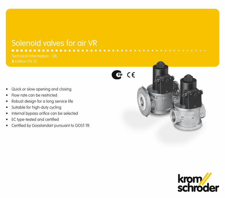
3 Edition 05.12Technical Information · GB
• Quick or slow opening and closing• Flow rate can be restricted• Robust design for a long service life• Suitable for high-duty cycling• Internal bypass orifice can be selected• EC type-tested and certified• Certified by Gosstandart pursuant to GOST-TR
Solenoid valves for air VR
VR · Edition 05.12 2▼ = To be continued
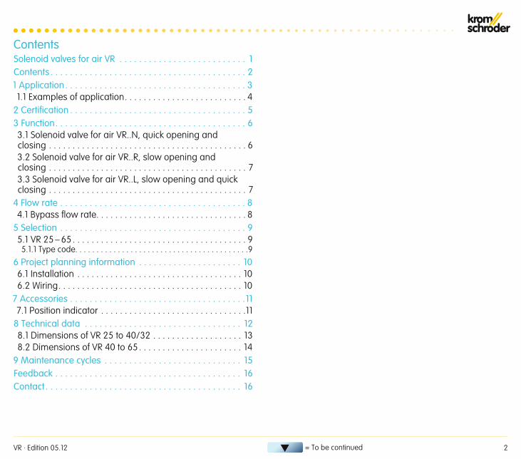
ContentsSolenoid valves for air VR . . . . . . . . . . . . . . . . . . . . . . . . . . 1Contents . . . . . . . . . . . . . . . . . . . . . . . . . . . . . . . . . . . . . . . . 21 Application . . . . . . . . . . . . . . . . . . . . . . . . . . . . . . . . . . . . . 31.1 Examples of application. . . . . . . . . . . . . . . . . . . . . . . . . . 4
2 Certification . . . . . . . . . . . . . . . . . . . . . . . . . . . . . . . . . . . . 53 Function . . . . . . . . . . . . . . . . . . . . . . . . . . . . . . . . . . . . . . . 63.1 Solenoid valve for air VR..N, quick opening and closing . . . . . . . . . . . . . . . . . . . . . . . . . . . . . . . . . . . . . . . . . . 63.2 Solenoid valve for air VR..R, slow opening and closing . . . . . . . . . . . . . . . . . . . . . . . . . . . . . . . . . . . . . . . . . . 73.3 Solenoid valve for air VR..L, slow opening and quick closing . . . . . . . . . . . . . . . . . . . . . . . . . . . . . . . . . . . . . . . . . . 7
4 Flow rate . . . . . . . . . . . . . . . . . . . . . . . . . . . . . . . . . . . . . . 84.1 Bypass flow rate. . . . . . . . . . . . . . . . . . . . . . . . . . . . . . . . 8
5 Selection . . . . . . . . . . . . . . . . . . . . . . . . . . . . . . . . . . . . . . 95.1 VR 25 – 65 . . . . . . . . . . . . . . . . . . . . . . . . . . . . . . . . . . . . . 95.1.1 Type code. . . . . . . . . . . . . . . . . . . . . . . . . . . . . . . . . . . . . . . . .9
6 Project planning information . . . . . . . . . . . . . . . . . . . . . 106.1 Installation . . . . . . . . . . . . . . . . . . . . . . . . . . . . . . . . . . . 106.2 Wiring. . . . . . . . . . . . . . . . . . . . . . . . . . . . . . . . . . . . . . . 10
7 Accessories . . . . . . . . . . . . . . . . . . . . . . . . . . . . . . . . . . . .117.1 Position indicator . . . . . . . . . . . . . . . . . . . . . . . . . . . . . . .11
8 Technical data . . . . . . . . . . . . . . . . . . . . . . . . . . . . . . . . 128.1 Dimensions of VR 25 to 40/32 . . . . . . . . . . . . . . . . . . . 138.2 Dimensions of VR 40 to 65 . . . . . . . . . . . . . . . . . . . . . . 14
9 Maintenance cycles . . . . . . . . . . . . . . . . . . . . . . . . . . . . 15Feedback . . . . . . . . . . . . . . . . . . . . . . . . . . . . . . . . . . . . . . 16Contact . . . . . . . . . . . . . . . . . . . . . . . . . . . . . . . . . . . . . . . . 16
VR · Edition 05.12 3
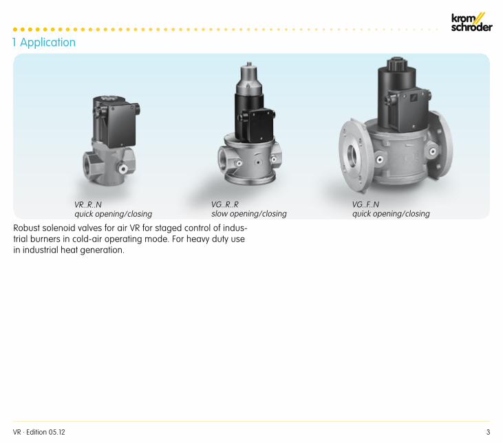
1 Application
Robust solenoid valves for air VR for staged control of indus-trial burners in cold-air operating mode. For heavy duty use in industrial heat generation.
VR..R..Nquick opening/closing
VG..R..Rslow opening/closing
VG..F..Nquick opening/closing
VR · Edition 05.12 4
Application
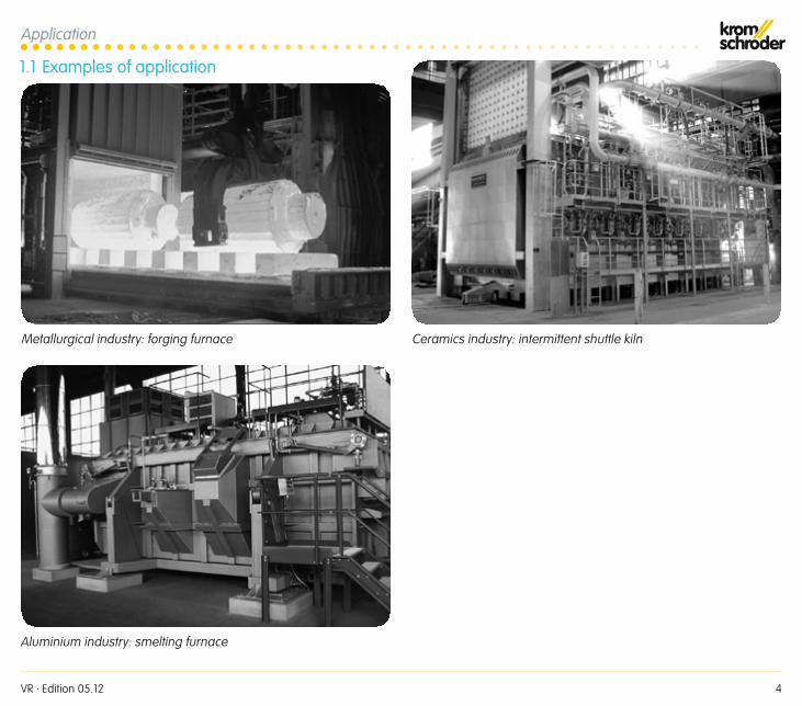
1 .1 Examples of application
Metallurgical industry: forging furnace
Aluminium industry: smelting furnace
Ceramics industry: intermittent shuttle kiln
VR · Edition 05.12 5
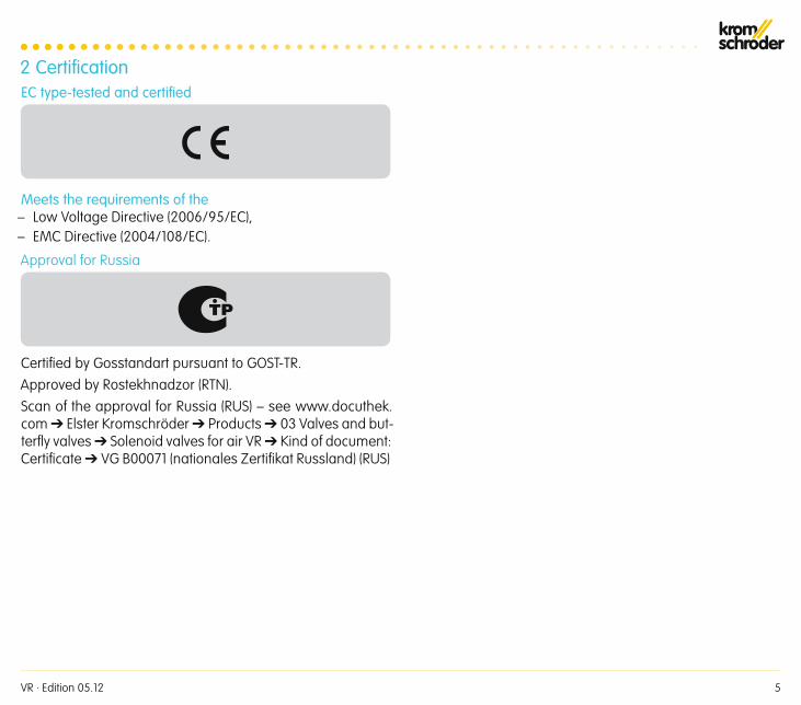
2 CertificationEC type-tested and certified
Meets the requirements of the– Low Voltage Directive (2006/95/EC),– EMC Directive (2004/108/EC).
Approval for Russia
Certified by Gosstandart pursuant to GOST-TR.Approved by Rostekhnadzor (RTN).Scan of the approval for Russia (RUS) – see www.docuthek.com ➔ Elster Kromschröder ➔ Products ➔ 03 Valves and but-terfly valves ➔ Solenoid valves for air VR ➔ Kind of document: Certificate ➔ VG B00071 (nationales Zertifikat Russland) (RUS)
VR · Edition 05.12 6
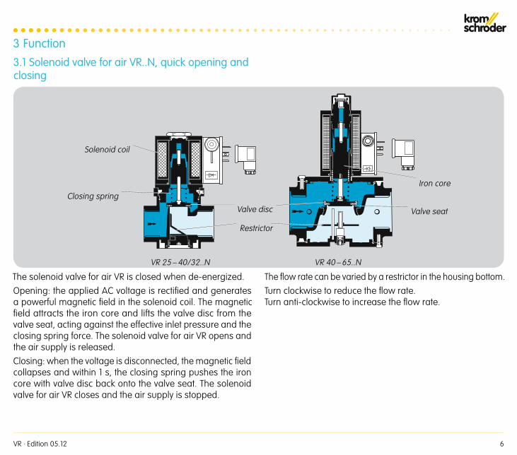
VR 25 – 40/32..N VR 40 – 65..N
3 Function3 .1 Solenoid valve for air VR . .N, quick opening and closing
Solenoid coil
Closing spring
Restrictor
Valve disc Valve seat
Iron core
The solenoid valve for air VR is closed when de-energized.Opening: the applied AC voltage is rectified and generates a powerful magnetic field in the solenoid coil. The magnetic field attracts the iron core and lifts the valve disc from the valve seat, acting against the effective inlet pressure and the closing spring force. The solenoid valve for air VR opens and the air supply is released.Closing: when the voltage is disconnected, the magnetic field collapses and within 1 s, the closing spring pushes the iron core with valve disc back onto the valve seat. The solenoid valve for air VR closes and the air supply is stopped.
The flow rate can be varied by a restrictor in the housing bottom.Turn clockwise to reduce the flow rate. Turn anti-clockwise to increase the flow rate.
VR · Edition 05.12 7
t
p d
t
p dp S
VR 25 – 40/32..R VR 40 – 65..R
Function
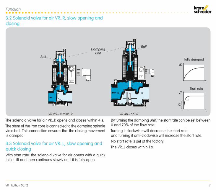
3 .2 Solenoid valve for air VR . .R, slow opening and closing
The solenoid valve for air VR..R opens and closes within 4 s.The stem of the iron core is connected to the damping spindle via a ball. This connection ensures that the closing movement is damped.
3 .3 Solenoid valve for air VR . .L, slow opening and quick closingWith start rate: the solenoid valve for air opens with a quick initial lift and then continues slowly until it is fully open.
By turning the damping unit, the start rate can be set between 0 and 70% of the flow rate:Turning it clockwise will decrease the start rate and turning it anti-clockwise will increase the start rate.No start rate is set at the factory.The VR..L closes within 1 s.
Start rate
fully damped
Damping unit
Ball
Ball
VR · Edition 05.12 8
0,50,6
0,81
2
3
456
8
6 7 8 10 20 30 40 50 60 80 100 200 300 400
Qn [m3/h]
600
10
20
30
4050
VR 2
5
VR 4
0
VR 5
0
VR 4
0/32
VR 6
5
∆p [m
bar] 100
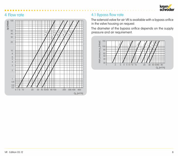
4 Flow rate 4 .1 Bypass flow rateThe solenoid valve for air VR is available with a bypass orifice in the valve housing on request.The diameter of the bypass orifice depends on the supply pressure and air requirement.
4 5 6 7 8 10 8020 30 40 5060
Qn [m3/h]1 2 3
30
40
5060
80
100
150
Ø 1
3 m
mØ
15
mm
Ø 1
1 m
m
Ø 9
mm
Ø 7
mm
Ø 3
mm
Ø 5
mm
Inle
t pre
ssur
e p u
[mba
r]
VR · Edition 05.12 9
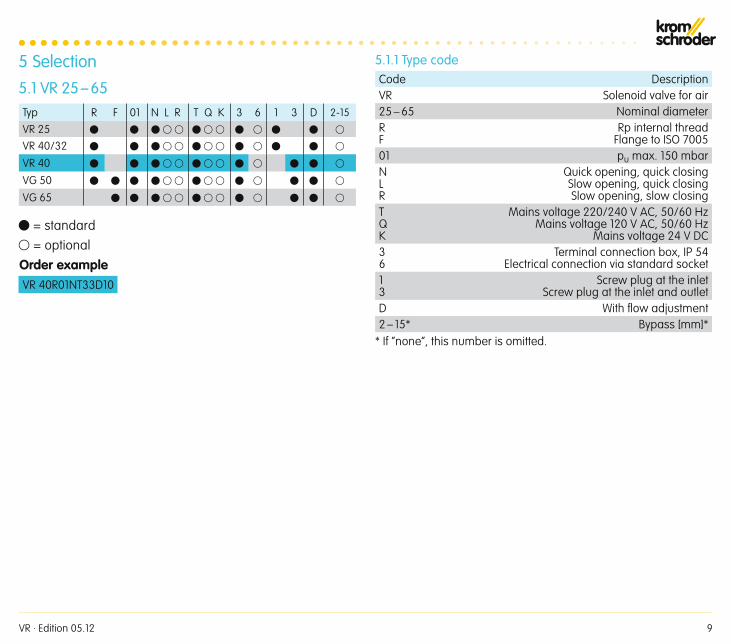
5 Selection5 .1 VR 25 – 65Typ R F 01 N L R T Q K 3 6 1 3 D 2-15
VR 25
VR 40/32
VR 40
VG 50
VG 65
= standard = optionalOrder exampleVR 40R01NT33D10
5 .1 .1 Type codeCode DescriptionVR Solenoid valve for air25 – 65 Nominal diameterRF
Rp internal threadFlange to ISO 7005
01 pu max. 150 mbarNLR
Quick opening, quick closingSlow opening, quick closingSlow opening, slow closing
TQK
Mains voltage 220/240 V AC, 50/60 HzMains voltage 120 V AC, 50/60 Hz
Mains voltage 24 V DC36
Terminal connection box, IP 54Electrical connection via standard socket
13
Screw plug at the inletScrew plug at the inlet and outlet
D With fl ow adjustment2 – 15* Bypass [mm]*
* If “none”, this number is omitted.
VR · Edition 05.12 10
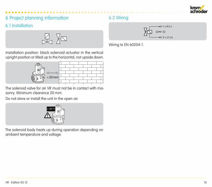
6 Project planning information6 .1 Installation
Installation position: black solenoid actuator in the vertical upright position or tilted up to the horizontal, not upside down.
> 20 mm
The solenoid valve for air VR must not be in contact with ma-sonry. Minimum clearance 20 mm.Do not store or install the unit in the open air.
> +80 °C
The solenoid body heats up during operation depending on ambient temperature and voltage.
6 .2 Wiring
1 = N (–)
2 = L1 (+)
Wiring to EN 60204-1.
VR · Edition 05.12 11
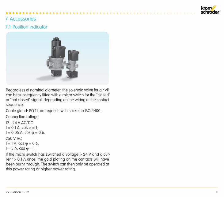
7 Accessories7 .1 Position indicator
Regardless of nominal diameter, the solenoid valve for air VR can be subsequently fitted with a micro switch for the “closed” or “not closed” signal, depending on the wiring of the contact sequence.Cable gland: PG 11, on request: with socket to ISO 4400.Connection ratings:12 – 24 V AC/DC I = 0.1 A, cos ϕ = 1, I = 0.05 A, cos ϕ = 0.6.250 V AC I = 1 A, cos ϕ = 0.6, I = 5 A, cos ϕ = 1.If the micro switch has switched a voltage > 24 V and a cur-rent > 0.1 A once, the gold plating on the contacts will have been burnt through. The switch can then only be operated at this power rating or higher power rating.
VR · Edition 05.12 12
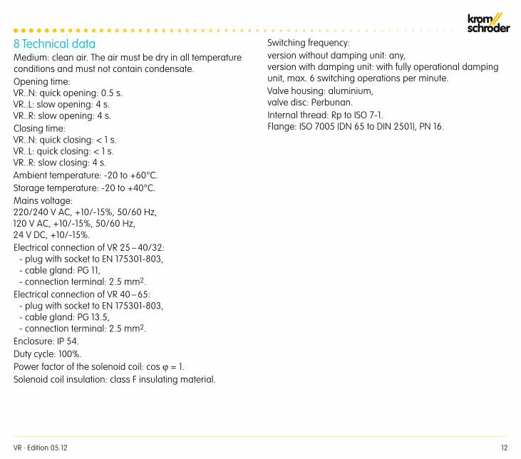
8 Technical dataMedium: clean air. The air must be dry in all temperature conditions and must not contain condensate.Opening time: VR..N: quick opening: 0.5 s. VR..L: slow opening: 4 s. VR..R: slow opening: 4 s.Closing time: VR..N: quick closing: < 1 s. VR..L: quick closing: < 1 s. VR..R: slow closing: 4 s.Ambient temperature: -20 to +60°C.Storage temperature: -20 to +40°C.Mains voltage: 220/240 V AC, +10/-15%, 50/60 Hz, 120 V AC, +10/-15%, 50/60 Hz, 24 V DC, +10/-15%.Electrical connection of VR 25 – 40/32:
- plug with socket to EN 175301-803, - cable gland: PG 11, - connection terminal: 2.5 mm2.
Electrical connection of VR 40 – 65: - plug with socket to EN 175301-803, - cable gland: PG 13.5, - connection terminal: 2.5 mm2.
Enclosure: IP 54.Duty cycle: 100%.Power factor of the solenoid coil: cos ϕ = 1.Solenoid coil insulation: class F insulating material.
Switching frequency: version without damping unit: any, version with damping unit: with fully operational damping unit, max. 6 switching operations per minute.Valve housing: aluminium, valve disc: Perbunan.Internal thread: Rp to ISO 7-1. Flange: ISO 7005 (DN 65 to DIN 2501), PN 16.
VR · Edition 05.12 13
Technical data
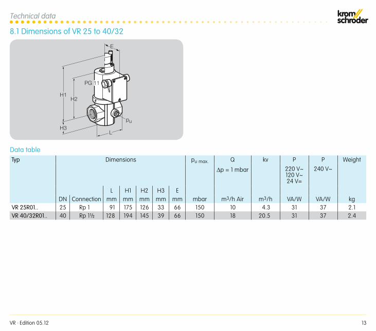
8 .1 Dimensions of VR 25 to 40/32
H2
L
H1
H3
PG 11
pu
E
Data tableTyp Dimensions pu max. Q kv P P Weight
∆p = 1 mbar 220 V~120 V~24 V=
240 V~
L H1 H2 H3 EDN Connection mm mm mm mm mm mbar m3/h Air m3/h VA/W VA/W kg
VR 25R01 . . 25 Rp 1 91 175 126 33 66 150 10 4.3 31 37 2.1VR 40/32R01 . . 40 Rp 1½ 128 194 145 39 66 150 18 20.5 31 37 2.4
VR · Edition 05.12 14
Technical data
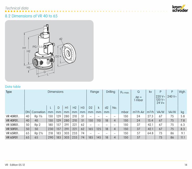
8 .2 Dimensions of VR 40 to 65
H1H2
PG 13,5
LD
H3
D2 k
d2
Data tableType Dimensions Flange Drilling pu max. Q kv P P Wgh.
∆p = 1 mbar
220 V~120 V~24 V=
240 V~
L D H1 H2 H3 D2 k d2 No.DN Connetion mm mm mm mm mm mm mm mm mbar m3/h Air m3/h VA/W VA/W kg
VR 40R01 . . 40 Rp 1½ 150 129 280 210 51 – – – – 150 24 27.3 67 75 5.8VR 40F01 . . 40 40 150 129 280 210 51 150 110 18 4 150 24 15.4 67 75 7.8VR 50R01 . . 50 Rp 2 180 157 291 221 62 – – – – 150 37 42.1 67 75 6.3VR 50F01 . . 50 50 230 157 291 221 62 165 125 18 4 150 37 42.1 67 75 8.3VR 65R01 . . 65 Rp 2½ 218 183 303 233 74 – – – – 150 57 64.8 73 86 9.1VR 65F01 65 65 290 183 303 233 74 185 145 18 4 150 57 73 86 11.1
VR · Edition 05.12 15
9 Maintenance cyclesAt least once per year.

VR · Edition 05.12
Finally, we are offering you the opportunity to assess this “Technical Information (TI)” and to give us your opinion, so that we can improve our documents further and suit them to your needs.
ClarityFound information quicklySearched for a long timeDidn’t find informationWhat is missing?
ComprehensionCoherentToo complicatedNo answer
ScopeToo littleSufficientToo wideNo answer
No answer
NavigationI can find my way aroundI got “lost”No answer
UseTo get to know the productTo choose a productPlanningTo look for information
My scope of functionsTechnical departmentSalesNo answer
Remarks
(Adobe Reader 7 or higher required) www.adobe.com
Elster GmbH Postfach 2809 · 49018 Osnabrück Strotheweg 1 · 49504 Lotte (Büren) GermanyT +49 541 1214-0 F +49 541 1214-370 [email protected] www.elster.com
The current addresses of our international agents are available on the Internet:www.kromschroeder.de/index.php?id=718&L=1
We reserve the right to make technical modifications in the interests of progress.Copyright © 2012 Elster Group All rights reserved.
Feedback
Contact
0325
1246