Embed Size (px)
Citation preview
SYSTEM BOARD D1 107SYSTEM BOARD D1 107SYSTEM BOARD D1 107SYSTEM BOARD D1 107
ADDITIONAL TECHNICALADDITIONAL TECHNICALADDITIONAL TECHNICALADDITIONAL TECHNICALMANUALMANUALMANUALMANUAL

Is there ...
... any technical problem or otherquestion you need clarified?
Please contact:• Our Hotline:
Mo-Fr: 8 a.m. - 6 p.m.Sat: 9 a.m. - 2 p.m.Tel.: ++49 (0) 180 3777 005
• your sales outlet
The latest information on our products, tips, updates, etc., can be found on the Internet under:http://www.fujitsu-siemens.com

Dieses Handbuch wurde auf Recycling-Papier gedruckt.This manual has been printed on recycled paper.Ce manuel est imprimé sur du papier recyclé.Este manual ha sido impreso sobre papel reciclado.Questo manuale è stato stampato su carta da riciclaggio.Denna handbok är tryckt på recyclingpapper.Dit handboek werd op recycling-papier gedrukt.
Herausgegeben von/Published byFujitsu Siemens Computers GmbH
Bestell-Nr./Order No.: A26361-D1107-Z180-10-7619A26361-D1107-Z180-10-7619A26361-D1107-Z180-10-7619A26361-D1107-Z180-10-7619Printed in the Federal Republic of GermanyAG 0100 01/00
A26361-D1107-Z180-1-7619
A26361-D1107-Z180-10-7619SYSTEM BOARD D1107
ADDITIONAL TECHNICAL MANUAL

System Board D1107
Additional Technical Manual
English
January 2000 edition

Copyright � Fujitsu Siemens Computers GmbH 2000
Intel, Pentium and Celeron are registered trademarks and MMX and OverDrive aretrademarks of Intel Corporation, USA.
Microsoft, MS, MS-DOS and Windows are registered trademarks of Microsoft Corporation.
PS/2 and OS/2 Warp are registered trademarks of International Business Machines, Inc.
All other trademarks referenced are trademarks or registered trademarks of their respectiveowners, whose protected rights are acknowledged.
All rights, including rights of translation, reproduction by printing, copying or similar methods,even of parts are reserved.
Offenders will be liable for damages.
All rights, including rights created by patent grant or registration of a utility model or design,are reserved. Delivery subject to availability.
Right of technical modification reserved.

A26361-D1107-Z180-10-7619
ContentsIntroduction........................................................................................................................................1
Notational conventions ..............................................................................................................1Features ............................................................................................................................................2Mechanics .........................................................................................................................................3
Connectors and Jumpers...........................................................................................................5I2C connector (for ambient/external temperature sensor) for optional temperature
sensor (LM75)............................................................................................................5Internal chipcard reader or serial port 2 (COM2) (external via wire) ...................................5Power supply ATX connector.............................................................................................6Wake on LAN (WOL) connector.........................................................................................6Power on switch connector (ON/OFF switch).....................................................................6Fan 2 connector for system fan or CPU fan (if external temperature sensor is in use) .......6Front panel connector (version 1) ......................................................................................7Front panel connector (version 2) ......................................................................................8USB chipcard reader connector .........................................................................................9Fan 1 connector for CPU fan or system fan (if external temperature sensor is in use) .......9Power supply monitoring....................................................................................................9Intrusion connector for case open detect for optional push-button (opener) .....................10System configurations .....................................................................................................10Hardware requirements ...................................................................................................11BIOS options ...................................................................................................................12Messages ........................................................................................................................12
Configuration ...........................................................................................................................13Clock frequency.......................................................................................................................13
Functions controlled by the switch block ..........................................................................14Power ......................................................................................................................................14
Power requirement ..........................................................................................................14Power loadability..............................................................................................................15
Documentation ................................................................................................................................15Installing drivers ..............................................................................................................................15Upgrades.........................................................................................................................................15
Main memory...........................................................................................................................15Troubleshooting...............................................................................................................................16
Message BIOS update.............................................................................................................16The screen stays blank............................................................................................................16


A26361-D1107-Z180-10-7619 1
Introduction
iThis system board is available in different configuration levels. Depending on thehardware configuration of your device, it may be that you cannot find several options inyour version of the system board, even though they are described.
You may find further information e. g. in the complete Technical Manual for the system board and inthe description "BIOS Setup". For detailed information see chapter "Documentation".
Further information to drivers is provided on the supplied drivers diskettes or on the "Drivers &Utilities" or "ServerStart" CD. For detailed information please look at chapter "Installing drivers". Thelatest BIOS version or drivers can be found on the internet underhttp://www.siemens.de/computer/service .
Notational conventionsThe meanings of the symbols and fonts used in this manual are as follows:
!Pay particular attention to texts marked with this symbol. Failure to observe this warningendangers your life, destroys the system, or may lead to loss of data.
iSupplementary information, remarks and tips follow this symbol.
Ê Texts which follow this symbol describe activities that must be performed in the order shown.
Ë This symbol means that you must enter a blank space at this point.
ÚÚÚÚ This symbol means that you must press the Enter key.
Texts in this typeface are screen outputs.
Texts in this bold typeface are the entries you make via the keyboard.
Texts in italics indicate commands or menu items.
"Quotation marks" indicate names of chapters and terms that are being emphasized.

Features
2 A26361-D1107-Z180-10-7619
FeaturesFunction D1107-A D1107-B
Processor socket Slot 1 Slot 1
Processor Intel Celeron or Pentium IIor Pentium III
Intel Celeron or Pentium IIor Pentium III
Formfactor ATX ATX
Front Side Bus in MHz 66/100 66/100
Chipset 440BX 440BX
Memory sockets 3 DIMM 3 DIMM
ISA slots 1 1
PCI slots 4 4
ISA/PCI shared 1 1
AGP-Port 1 1
System monitoring x x
Thermal Management x x
Wake On LAN x x
Keyboard On x x
IrDA
Chipcard reader x x
Save to Disk (ACPI S4) x x
Save to RAM(ACPI S3) x x
LAN onboard x - -
Audio onboard - - - -
VGA onboard - - - -
4MB Display Cache - - - -
!Computer system boards and components contain very delicate IC chips. To protect themagainst damage caused from electric static, you have to follow some precautions:
• Unplug your computer when you work inside.
• Hold components by the edge, don't touch their leads.
• Use a grounded wrist strap.
Place the system board and the components on a grounded antistatic pad whenever youwork outside the computer.
Once you have installed the system board, you should remove the battery protection (i.e.the thin plastic plate between battery and contact spring).

Mechanics
A26361-D1107-Z180-10-7619 3
Mechanics
Layout
ATX 12"' x 8'' (304,8 mm x 203,2 mm)
Some of the following connectors are optional and may therefore not be included on your systemboard.
21
AG
P
Slot 1
3
PC
I5
PC
I2
PC
I1
PC
I3
PC
I4 ISA
1
ISA
2
41 3 6
2 5
7
1 = Serial port 12 = PS/2 mouse port3 = PS/2 keyboard port
4 = Parallel port5 = USB connection 26 = USB connection 17 = LAN port
The components and connectors marked do not have to be present on the system board.

Mechanics
4 A26361-D1107-Z180-10-7619
21
AG
P
Slot 1
3
PC
I5
PC
I2
PC
I1
PC
I3
PC
I4 ISA
1
ISA
2
1 2 3 4 5 6 7 8 9
12
13
14
11
15
10
1 = I2C connector (for temperature sensor)2 = Internal chipcard reader or serial port 23 = Power supply4 = Floppy disk drive5 = IDE drives 3 and 4 (secondary)6 = Wake On LAN7 = ON/OFF switch8 = Fan 2
9 = IDE drives 1 and 2 (primary)10 = Front panel connector11 = IrDA12 = USB chipcard reader13 = Fan 1 (e. g. for the processor)14 = Power supply monitoring15 = Intrusion connector *
The components and connectors marked do not have to be present on the system board.*: For correct installation please refer to chapter "Temperature monitoring / system monitoring" inthe Technical Manual.

Mechanics
A26361-D1107-Z180-10-7619 5
Connectors and Jumpers
!Some of the following connectors are optional!
I2C connector (for ambient/externaltemperature sensor) for optionaltemperature sensor (LM75)
1
Pin Signal
1 3.3 V standby2 Clock3 Data4 GNDRefer to chapter "Temperature monitoring / system monitoring" in the Technical Manual.
Internal chipcard reader or serialport 2 (COM2) (external via wire)
1
2
Pin Signal Pin Signal
1 DCD 2 (low asserted) 2 DSR 2 (low asserted)3 SIN 2 (high asserted) 4 RTS 2 (low asserted)5 SOUT 2 (high asserted) 6 CTS 2 (low asserted)7 DTR 2 (low asserted) 8 PC_ON_Strobe9 GND 10 VCC Auxiliary11 EXT SMI (low asserted) 12 VCC13 RESETDRV (high asserted) 14 GND15 GND 16 Key

Mechanics
6 A26361-D1107-Z180-10-7619
Power supply ATX connector
10
20
1
11
Pin Signal Pin Signal
1 +3.3 V 2 +3.3 V3 GND 4 +5 V5 GND 6 +5 V7 GND 8 Powergood (high asserted)9 +5 V Auxiliary 10 +12 V11 +3.3 V 12 -12 V13 GND 14 PS on (low asserted)15 GND 16 GND17 GND 18 -5 V19 +5 V 20 +5 V
Wake on LAN (WOL) connector 1
Pin Signal
1 +5 V Auxiliary2 GND3 Wake pulse (high asserted)
Power on switch connector (ON/OFFswitch)
1
Pin Signal
1 GND2 Power on pulse (low asserted)
Fan 2 connector for system fan orCPU fan (if external temperaturesensor is in use)
1
Pin Signal
1 GND2 +12 V3 Fan senseRefer to chapter "Temperature monitoring / system monitoring" in the Technical Manual.

Mechanics
A26361-D1107-Z180-10-7619 7
Front panel connector (version 1)
12
Reset adapter1)
HD-LED2)
2) Cable is not included in the delivery scope.3) The same interface.
1) Reset adapter from 4pin female to 2pin male.
Power On LED2)
SCSI LED Input3)2)
Speaker2)
Message LED2)
Pin Signal Pin Signal
1 Reserved 2 Speaker3 Anode Standby LED 4 Key5 Key 6 GND7 Anode PON_LED 8 VCC9 Not connected 10 Key pin11 Cathode PON_LED (GND) 12 Key13 Anode Message LED 14 Key15 Cathode Message LED 16 Key pin17 Key 18 Key19 Anode HD_LED 20 Key21 Cathode HD_LED 22 Key23 GND (for Reset and Power button) 24 Not connected25 Power Button 26 SCSI LED Input27 Not connected 28 SCSI LED Input29 Reset Button 30 Not connected

Mechanics
8 A26361-D1107-Z180-10-7619
Front panel connector (version 2)
12
HD-LED1)
1) Cable is not included in the delivery scope.2) The same interface.
Power On LED1)
Power On/Off
SCSI LED Input2)1)
Reset1)
Message LED1)
Speaker2)
Pin Signal Pin Signal
1 Reserved 2 Speaker3 Anode Standby LED 4 Key5 Key 6 GND7 Anode PON_LED 8 VCC9 Not connected 10 Key pin11 Cathode PON_LED (GND) 12 Key pin13 Anode Message LED 14 Key15 Cathode Message LED 16 Not connected17 Key 18 SCSI LED Input19 Anode HD_LED 20 SCSI LED Input21 Cathode HD_LED 22 Not connected23 GND (for Reset and Power button) 24 Key25 Power Button 26 GND27 Not connected 28 GND29 Reset Button 30 GND

Mechanics
A26361-D1107-Z180-10-7619 9
USB chipcard reader connector
1
2
Pin Signal Pin Signal
1 P3V3P_DUAL 2 VCC3 Data negative output up 4 Data positive up5 Data negative 6 Data positive down7 GND 8 GND9 Chipcard present (high asserted) 10 VCC Auxiliary11 P3V3P 12 Power OK (low asserted)13 Chipcard reader On (low pulse) 14 Key
Fan 1 connector for CPU fan orsystem fan (if external temperaturesensor is in use) 1
Pin Signal
1 GND2 6 - 12 V; 0 V3 Fan senseRefer to chapter "Temperature monitoring / system monitoring" in the Technical Manual.
Power supply monitoring1
Pin Signal
1 Monitor on2 PS FAN off request (low asserted)3 PS FAN full on (low asserted)4 PS FAN pulse5 SMB CLK6 SMB DATA7 VCC EEPROM8 GNDRefer to chapter "Temperature monitoring / system monitoring" in the Technical Manual.

Mechanics
10 A26361-D1107-Z180-10-7619
Intrusion connector for case opendetect for optional push-button(opener)
1
Pin Signal
1 GND2 Case open (low asserted)3 Present (low asserted)Refer to chapter "Temperature monitoring / system monitoring" in the Technical Manual.
System configurations
Systems with ... Standard ATX power supply
Example 1 2 3
Standard Workstation Server
T0 processortemperature
Sensor in CPU integrated
T1 system temperature Sensor onboardT2 external temperature
via optional LM75sensor
- - - - yes
Fan 0destination - - - - - -supervision - - - - - -control - - - - - -
Fan 1destination processor fan processor fan system fansupervision yes yes yescontrol yes (0 V, 6-12 V) yes (0 V, 6-12 V) yes (0 V, 6-12 V)
Fan 2destination - - system fan system fansupervision - - yes yes
control - - no (12 V) no (12 V)

Mechanics
A26361-D1107-Z180-10-7619 11
Systems with ... Extended ATX power supply
Example 1 2 3
Standard Workstation Server
T0 processortemperature
Sensor in CPU integrated
T1 system temperature Sensor onboardT2 external temperature
via optional LM75sensor
- - - - yes
Fan 0destination power supply fansupervision yescontrol yes (0 V, 6-12 V)
Fan 1destination - - - - system fansupervision - - - - yescontrol - - - - yes (0 V, 6-12 V)
Fan 2destination - - - - processor fan
supervision - - - - yes
control - - - - no (12 V)
Hardware requirements
Power supply:
Power supply fan must be controllable by system board (22KHz PWM signal with 3.3V) and needs asense-pin for rpm-measurement.
Fan sense: 2 ripples per rotation
Ripple pulsewidth:
T low and T high > 0.6 ms
Number ofrevolutions
at 100% PWM: maximum 14000 Rpm
at 50% PWM: minimum 800 Rpm
e.g.: Siemens S26113-E425 or. E427

Mechanics
12 A26361-D1107-Z180-10-7619
Fan:
The fan speed must be controllable from 6 - 12 V (start voltage: 12 V). Therefore the fan must havea mechanical suitability as well as a 3-pole-plug with a sense-pin for rpm-measurement.
Fan sense: 2 ripples per rotation
Ripple pulsewidth:
T low and T high > 0.6 ms
Current: blocking fan at 12 V: 1.6 A
rotating fan at 6V / 12V: 0.3A / 0.6 A
number ofrevolutions
at 12V: maximum 14000 Rpm
at 6V: minimum 800 Rpm
e.g.: Papst type 412 F/2H as processor fan
Sensor for internal temperature:
Housing temperature is read by an onboard sensor.
CPU temperature is read by an onboard sensor but only with processors which have an integratedtemperature diode.
Sensor for external temperature:
Use only a Siemens Sensor: e.g. T26139-Y3718-V1
Intrusion logic:
Push-button (type: opener, if housing is open pins 1 and 2 are connected).
BIOS options
Please refer to BIOS description on the including CD-ROM (menuAdvanced System Management ).
Messages
Message LED:The Message LED (frontpanel connector) shows two different statesA slow blinking (once a second) of the LED signals that any application has receiveda message. (ACPI- mode)A fast blinking (five times a second) of the LED signals a hardware problem. Moredetailed information are shown with an additional System Monitoring Software or onthe monitor after reboot entering BIOS Setup (menuAdvanced System Management ) .The fast blinking LED can have several different causes.
- a necessary sensor is missing or defect- an available sensor has overtemperature- a fan is defect or not working properly- a software is responsible for blinking
BIOS: Please refer to BIOS description on the including CD-ROM.
Mechanics
A26361-D1107-Z180-10-7619 13
Configuration
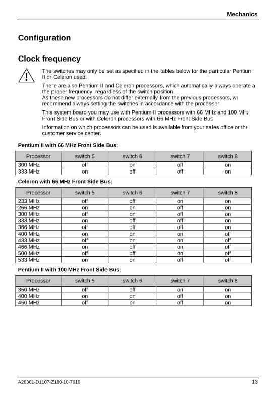
Clock frequency
!The switches may only be set as specified in the tables below for the particular PentiumII or Celeron used.
There are also Pentium II and Celeron processors, which automatically always operate atthe proper frequency, regardless of the switch position.As these new processors do not differ externally from the previous processors, werecommend always setting the switches in accordance with the processor.
This system board you may use with Pentium II processors with 66 MHz and 100 MHzFront Side Bus or with Celeron processors with 66 MHz Front Side Bus
Information on which processors can be used is available from your sales office or thecustomer service center.
Pentium II with 66 MHz Front Side Bus:
Processor switch 5 switch 6 switch 7 switch 8
300 MHz off on off on333 MHz on off off on
Celeron with 66 MHz Front Side Bus:
Processor switch 5 switch 6 switch 7 switch 8
233 MHz off off on on266 MHz on on off on300 MHz off on off on333 MHz on off off on366 MHz off off off on400 MHz on on on off433 MHz off on on off466 MHz on off on off500 MHz off off on off533 MHz on on off off
Pentium II with 100 MHz Front Side Bus:
Processor switch 5 switch 6 switch 7 switch 8
350 MHz off off on on400 MHz on on off on450 MHz off on off on
Mechanics
14 A26361-D1107-Z180-10-7619
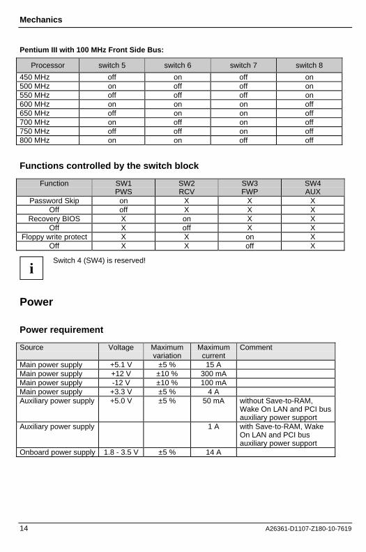
Pentium III with 100 MHz Front Side Bus:
Processor switch 5 switch 6 switch 7 switch 8
450 MHz off on off on500 MHz on off off on550 MHz off off off on600 MHz on on on off650 MHz off on on off700 MHz on off on off750 MHz off off on off800 MHz on on off off
Functions controlled by the switch block
Function SW1PWS
SW2RCV
SW3FWP
SW4AUX
Password Skip on X X XOff off X X X
Recovery BIOS X on X XOff X off X X
Floppy write protect X X on XOff X X off X
iSwitch 4 (SW4) is reserved!
Power
Power requirement
Source Voltage Maximumvariation
Maximumcurrent
Comment
Main power supply +5.1 V ±5 % 15 AMain power supply +12 V ±10 % 300 mAMain power supply -12 V ±10 % 100 mAMain power supply +3.3 V ±5 % 4 AAuxiliary power supply +5.0 V ±5 % 50 mA without Save-to-RAM,
Wake On LAN and PCI busauxiliary power support
Auxiliary power supply 1 A with Save-to-RAM, WakeOn LAN and PCI busauxiliary power support
Onboard power supply 1.8 - 3.5 V ±5 % 14 A

Documentation
A26361-D1107-Z180-10-7619 15
Power loadability
Fusenumber
Maximum Fusecurrent
Function Maximum function current
1 750 mA Universal serial bus (USB) Port A 500 mAKeyboard Not specified
Mouse Not specified2 750 mA Universal serial bus (USB) Port B 500 mA
DocumentationÊ Insert the "Drivers & Utilities" CD.
Ê If the CD does not start automatically, run the START.EXE file in the main directory of the CD.
Ê Select your system board or your device.
Ê Select Documentation.
Ê Select - Technical Manuals
Ê Select - Technical Manuals (BIOS)
iYou may have to install the Acrobat Reader - Software on the CD-ROM (pathutls/acrobat) before reading!
For more details please read the according readme.txt files.
Installing driversÊ Insert the "Drivers & Utilities" CD.
Ê If the CD doesn't start automatically call the START.EXE file in the main directory of the CD.
Ê If the system board list is displayed select the system board or select under Driver theoperating system used and the audio and video drivers.
Upgrades
Main memorySupport: The system needs at least one module and can manage at most three SDRAM
modules.
PC100 modules must have an SPD-EEPROM*.It is not possible to mix SDRAM and EDO modules.
Size: From 16 Mbytes up to 768 Mbytes SDRAM

Troubleshooting
16 A26361-D1107-Z180-10-7619
Technology: 100 MHz unbuffered DIMM modules.168 pin, 3.3V, 100 MHz SDRAM2M, 4M, 8M, 16M and 32M x 64 bit2M, 4M, 8M, 16M and 32M x 72 bit (with ECC)
Granularity: For one socket 16, 32, 64, 128 or 256 Mbyte
* The EEPROM of PC100 modules contains a number of critical timing parameters and dataregarding the chip and the module vendor. Due to this the system board will properly recognizethe module by reading all important timing parameters specified in the EEPROM via theSerialPresence Detect interface.
Troubleshooting
Message BIOS updateThe System BIOS provides optimum support for the processor you have chosen. If the message
BIOS update for installed CPU failed
appears the microcode required for the processor inserted must still be loaded. Further informationon this is available in the "BIOS Setup" manual on the "Drivers & Utilities" CD provided.
The screen stays blankIf your screen stays blank this may have the following cause:
The wrong RAM memory module has been inserted
Ê See the chapter "Main Memory" for information which memory modules can be used.
ACPI S3 (Save-to-RAM) and/or ACPI S4 (Save-to-Disk) doesn't work
This system board is fully compliant for ACPI S3 and S4. Therefore it is PC98 certified by Microsoft.
If you have any problems with ACPI please ensure that all of your components are supporting ACPIS3 and S4.
− Operating System
− Hardware and drivers of controllers (e. g. VGA, audio, LAN, SCSI controllers).
!The system board D1107 supports Save-to-RAM. Therefore the D1107 is certified by Inteand Microsoft. This support must be also guaranteed by the operating system, theextension boards and the power supply. For the time neither Windows 98 nor WindowsNT4.0 support this function reliably. Windows 2000 will support ACPI S3 fullyUnfortunately only a few extension boards work with a functional Save-to-RAM support(refer to http://developer.intel.com/technology/iapc/involve.htm ). For the ATX power supply werecommend a auxiliary power supply of 5V/1A.