Embed Size (px)
Citation preview

1
Systeem en RegeltechniekSysteem en RegeltechniekFMT / FMT / MechatronicaMechatronica
Gert van Schothorst
Philips Centre for Technical Training (CTT)Philips Centre for Industrial Technology (CFT)Hogeschool van Utrecht - PTGroep
Deel 5:Deel 5: ToepassingToepassing: PID : PID regelaarontwerpregelaarontwerpOefening:Oefening: ToepassingToepassing: : TunenTunen PID PID regelaar mechatronisch systeemregelaar mechatronisch systeem
(update dd. 21(update dd. 21--0505--2004)2004)
2Philips Centre for Technical Training (CTT) / Philips Centre for Industrial Technology (CFT) / HvU PTGroep – Gert van Schothorst
Cursus Systeem en RegeltechniekCursus Systeem en RegeltechniekOverzichtOverzicht
Deel 1 Blok 1. InleidingWo. 14-04 Blok 2. Basisprincipes modelvorming massa-veersystemen
Blok 3. De regelaar als veer-demper combinatie
Deel 2 Blok 4. Frequentie-domein beschrijvingWo. 21-04 Blok 5. Basisconcepten in de regeltheorie
Deel 3 Blok 6. Verdere inleiding in de regeltheorieWo. 28-04 Blok 7. De PD regelaar als veer-demper combinatie
Deel 4 Blok 8. Stabiliteit van regelsystemenWo. 12-05 Blok 9. De PID regelaar in het frequentie domein
Deel 5 Blok 10. Bandbreedte en verstoringsonderdrukkingWo. 19-05 Blok 11. Toepassing: Tunen PID regelaar mechatronisch systeem
Deel 6 Blok 12. Diverse onderwerpenWo. 26-05 Blok 13. Terugblik
Extra regeltechniek

2
3Philips Centre for Technical Training (CTT) / Philips Centre for Industrial Technology (CFT) / HvU PTGroep – Gert van Schothorst
Tuning the PID controller:Tuning the PID controller:what does that mean in practice?what does that mean in practice?
?Application: Tuning PID controller mechatronic system
4Philips Centre for Technical Training (CTT) / Philips Centre for Industrial Technology (CFT) / HvU PTGroep – Gert van Schothorst
Mechatronic Mechatronic systemsystem
Moving target: 3 Hz, 3mm
Allowed tracking error: 40µµµµm
Application: Tuning PID controller mechatronic system

3
5Philips Centre for Technical Training (CTT) / Philips Centre for Industrial Technology (CFT) / HvU PTGroep – Gert van Schothorst
Data MechanicsData Mechanics
Motor inertia: 2.5××××10-5 [Kgm2]Motor gear wheel inertia: 2.5××××10-5 [Kgm2] Gear+pinion wheel inertia: 5.0××××10-5 [Kgm2] Mass slide: 5.0 KgMass camera: 3.0 KgTransmission gearbox: 0.2 [-]Diameter pinion wheel: 30 [mm]
Application: Tuning PID controller mechatronic system
6Philips Centre for Technical Training (CTT) / Philips Centre for Industrial Technology (CFT) / HvU PTGroep – Gert van Schothorst
Objective ExerciseObjective Exercise
• Dimension a stable control loop in which the error is reduced to 40 µm
• The phase margin at the crossover is about 50 degrees Moving target: 3 Hz, 3mm
Allowed tracking error: 40µµµµm
Application: Tuning PID controller mechatronic system

4
7Philips Centre for Technical Training (CTT) / Philips Centre for Industrial Technology (CFT) / HvU PTGroep – Gert van Schothorst
Exercise Exercise -- Part 1Part 1
• Assignment 1:Sketch a simple model without flexibilities
• All elements included• Reduced model with single mass
• Assignment 2:Implement the model in 20-sim
• Assignment 3: Design a PD controller and check performance
Solve the sketched control problem for a system without flexibilities
Application: Tuning PID controller mechatronic system
8Philips Centre for Technical Training (CTT) / Philips Centre for Industrial Technology (CFT) / HvU PTGroep – Gert van Schothorst
Assignment 1:Assignment 1:Model without flexibilitiesModel without flexibilities
Tmotor
Jmotor Jgear
Mslide
Mcamera
φmotor
xcamera
Jgear+pinion
Application: Tuning PID controller mechatronic system

5
9Philips Centre for Technical Training (CTT) / Philips Centre for Industrial Technology (CFT) / HvU PTGroep – Gert van Schothorst
Assignment 1:Assignment 1:Model without flexibilitiesModel without flexibilities
Jgear Mslide McameraTmotor
φmotor xcamera
Jmotor
Jgr+pin
i1 = 0.2 [-]
i2 = 0.015 [m/rad]
Reduced model (to camera):
F
x
Mred
Mred = Mcamera + Mslide + Jgr+pin/i22
+ (Jgear+Jmotor)/(i12i22)
Application: Tuning PID controller mechatronic system
10Philips Centre for Technical Training (CTT) / Philips Centre for Industrial Technology (CFT) / HvU PTGroep – Gert van Schothorst
Assignment 2:Assignment 2:Implementation in 20Implementation in 20--simsim
Application: Tuning PID controller mechatronic system
Constant1
P
PositionSensor1
J
Inertia3m
Mass2
m
Mass1RackPinionGear1
1
i
Gear1
J
Inertia2
J
Inertia1
T
TorqueActuator1
• Linearise model via:
• Ctrl-R (Start Simulator)
• Tools – Model Linearisation; choose option ‘Numeric’
• Does the ‘Mass’ of the obtained model correspond to the reduced mass? No! Why not? And why is the minus sign?!
• Use obtained linear system (transfer function properties) as ‘Plant’ in new submodel ‘Controlled Linear System’

6
11Philips Centre for Technical Training (CTT) / Philips Centre for Industrial Technology (CFT) / HvU PTGroep – Gert van Schothorst
Assignment 2:Assignment 2:Implementation in 20Implementation in 20--simsim
Application: Tuning PID controller mechatronic system
SignalMonitor1
WaveGenerator1
Constant1
F C
M
r Pd
z
ControlledLinearSystem1
3 Hz, 3 mm
Build controlled linear system as follows:
Now the controller design can be performed
12Philips Centre for Technical Training (CTT) / Philips Centre for Industrial Technology (CFT) / HvU PTGroep – Gert van Schothorst
Assignment 3:Assignment 3:Design a PD controller and check performanceDesign a PD controller and check performance
Follow these steps:1. Determine the needed reduction at 3 Hz2. Determine the needed bandwidth fb (0 dB crossing of open
loop), assuming Kp controller3. Tune a Lead Filter (also called lead-lag):
1. Adjust the width of the lead-lag filter (f1; f2) for the required phase margin; position the lead-lag around the required bandwidth by choosing: f1 = fb/n; f2 = fb*n
2. Adjust the gain to place the 0 dB crossing of the open loop at the required bandwidth
4. Check stability in Nyquist; check the reduction at 3 Hz in sensitivity plot
5. Repeat tuning Lead Filter if necessary6. Check the reduction via a time plot with 3 Hz sine
Application: Tuning PID controller mechatronic system

7
13Philips Centre for Technical Training (CTT) / Philips Centre for Industrial Technology (CFT) / HvU PTGroep – Gert van Schothorst
Assignment 3:Assignment 3:Design a PD controller and check performanceDesign a PD controller and check performance
Step 1: Determine the needed reduction at 3 Hz
S (3Hz) = e (3Hz) / d (3Hz) = 40 µm / 3 mm = 0.013
So a reduction of the error with a factor 75 is needed @ 3 Hz
This corresponds to a sensitivity value @ 3 Hz of -37,5 dB
With S = 1 / (1 + L), with L the open loop response C(s)H(s), this means roughly that L should be larger than 37,5 dB @ 3 Hz
14Philips Centre for Technical Training (CTT) / Philips Centre for Industrial Technology (CFT) / HvU PTGroep – Gert van Schothorst
Assignment 3:Assignment 3:Design a PD controller and check performanceDesign a PD controller and check performance
Step 2: Determine the needed bandwidth fb
So we have: C(s)H(s) > 37,5 dB @ 3 Hz
Assuming a Kp controller, the open loop looks like: K/s2
K/s2
37,5 dB
0 dB
-2
3 Hz fb
K/(2� 3)2 = 75; K/(2� fb)2 = 1
(fb/3)2 = 75
fb = 26 Hz
Kp = K / -24.19 = -1100
Note the minus sign!
8
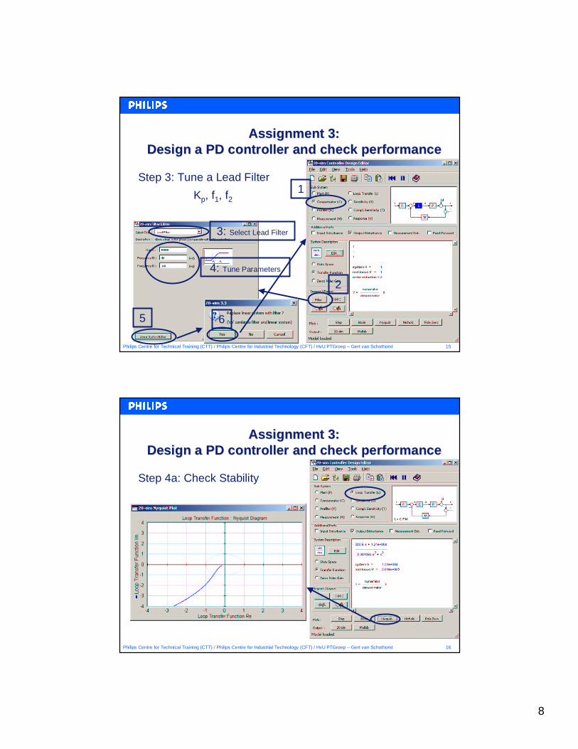
15Philips Centre for Technical Training (CTT) / Philips Centre for Industrial Technology (CFT) / HvU PTGroep – Gert van Schothorst
Assignment 3:Assignment 3:Design a PD controller and check performanceDesign a PD controller and check performance
Step 3: Tune a Lead Filter1
2
3: Select Lead Filter
4: Tune Parameters
5 6
Kp, f1, f2
16Philips Centre for Technical Training (CTT) / Philips Centre for Industrial Technology (CFT) / HvU PTGroep – Gert van Schothorst
Assignment 3:Assignment 3:Design a PD controller and check performanceDesign a PD controller and check performance
Step 4a: Check Stability
9
17Philips Centre for Technical Training (CTT) / Philips Centre for Industrial Technology (CFT) / HvU PTGroep – Gert van Schothorst
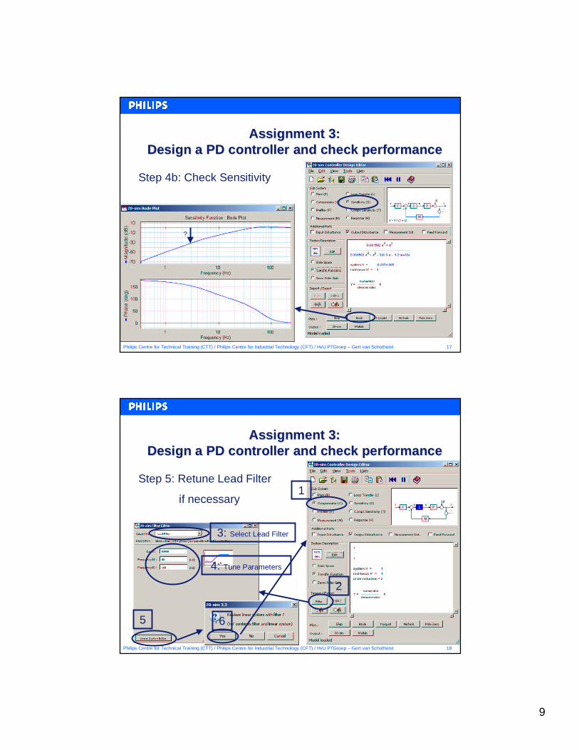
Assignment 3:Assignment 3:Design a PD controller and check performanceDesign a PD controller and check performance
Step 4b: Check Sensitivity
?
18Philips Centre for Technical Training (CTT) / Philips Centre for Industrial Technology (CFT) / HvU PTGroep – Gert van Schothorst
Assignment 3:Assignment 3:Design a PD controller and check performanceDesign a PD controller and check performance
Step 5: Retune Lead Filter
if necessary1
2
3: Select Lead Filter
4: Tune Parameters
5 6
10
19Philips Centre for Technical Training (CTT) / Philips Centre for Industrial Technology (CFT) / HvU PTGroep – Gert van Schothorst
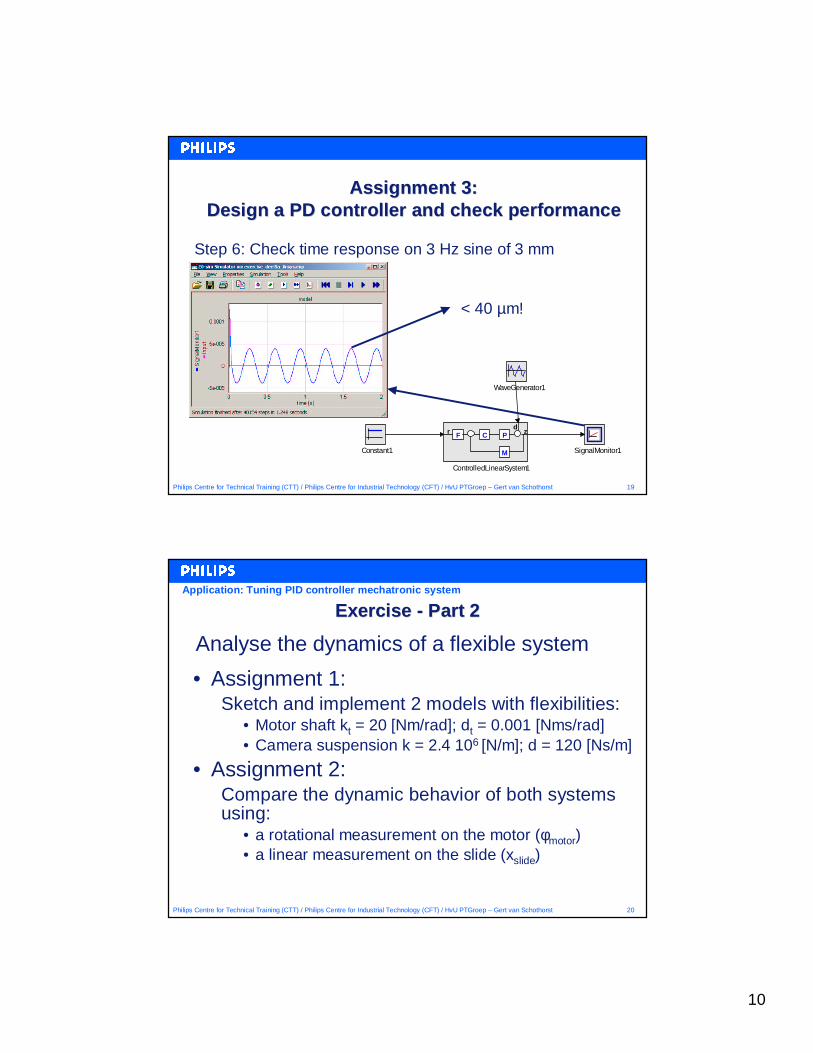
Assignment 3:Assignment 3:Design a PD controller and check performanceDesign a PD controller and check performance
Step 6: Check time response on 3 Hz sine of 3 mm
SignalMonitor1
WaveGenerator1
Constant1
F C
M
r Pd
z
ControlledLinearSystem1
< 40 µm!
20Philips Centre for Technical Training (CTT) / Philips Centre for Industrial Technology (CFT) / HvU PTGroep – Gert van Schothorst
Exercise Exercise -- Part 2Part 2
• Assignment 1:Sketch and implement 2 models with flexibilities:
• Motor shaft kt = 20 [Nm/rad]; dt = 0.001 [Nms/rad]• Camera suspension k = 2.4 106 [N/m]; d = 120 [Ns/m]
• Assignment 2:Compare the dynamic behavior of both systems using:
• a rotational measurement on the motor (φmotor)• a linear measurement on the slide (xslide)
Analyse the dynamics of a flexible system
Application: Tuning PID controller mechatronic system
11
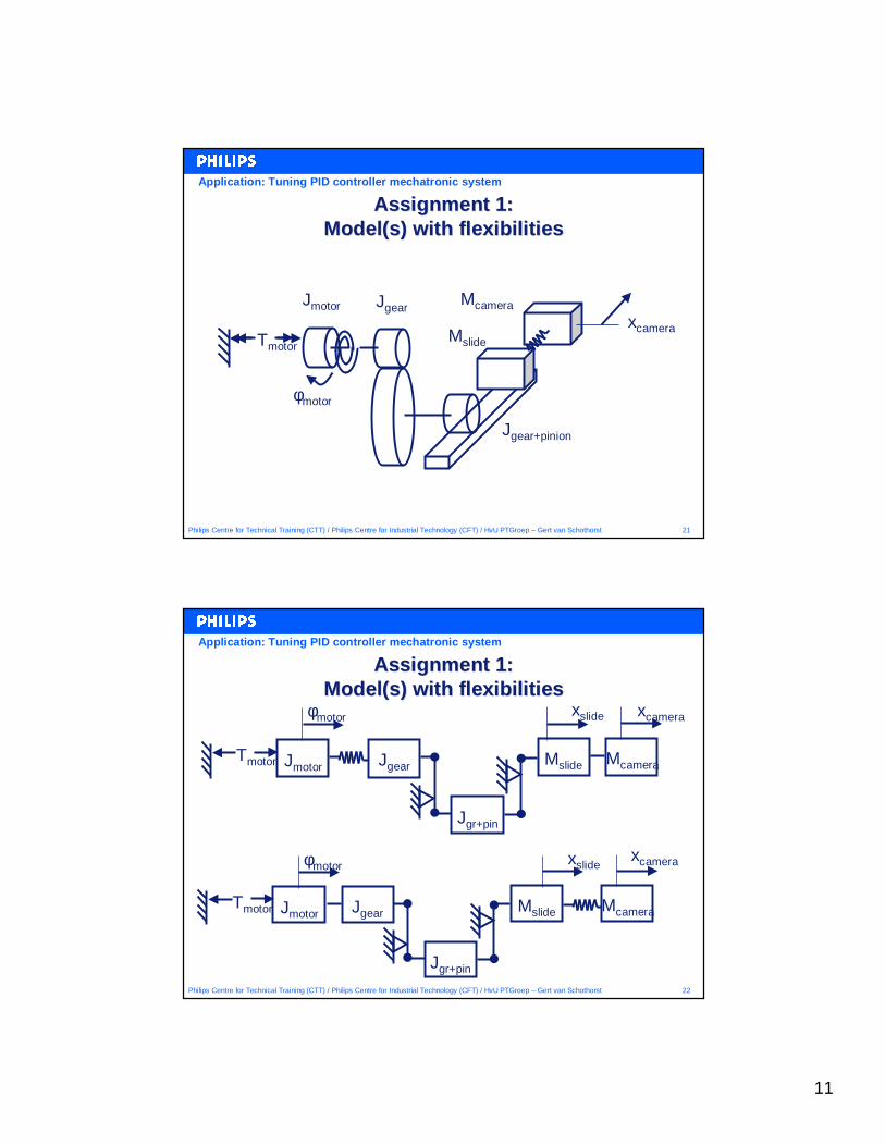
21Philips Centre for Technical Training (CTT) / Philips Centre for Industrial Technology (CFT) / HvU PTGroep – Gert van Schothorst
Assignment 1:Assignment 1:Model(s) with flexibilitiesModel(s) with flexibilities
Tmotor
Jmotor Jgear
Mslide
Mcamera
φmotor
xcamera
Jgear+pinion
Application: Tuning PID controller mechatronic system
22Philips Centre for Technical Training (CTT) / Philips Centre for Industrial Technology (CFT) / HvU PTGroep – Gert van Schothorst
Assignment 1:Assignment 1:Model(s) with flexibilitiesModel(s) with flexibilities
xcamera
Jgear Mslide McameraTmotor
φmotor
Jmotor
Jgr+pin
xslide
Jgear Mslide McameraTmotor
φmotor
Jmotor
Jgr+pin
xslide xcamera
Application: Tuning PID controller mechatronic system
12
23Philips Centre for Technical Training (CTT) / Philips Centre for Industrial Technology (CFT) / HvU PTGroep – Gert van Schothorst
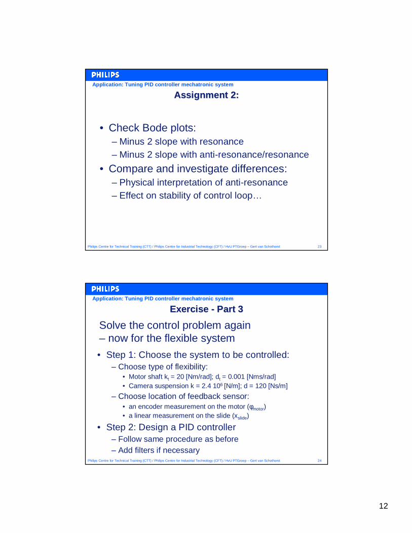
Assignment 2:Assignment 2:
• Check Bode plots:– Minus 2 slope with resonance– Minus 2 slope with anti-resonance/resonance
• Compare and investigate differences:– Physical interpretation of anti-resonance– Effect on stability of control loop…
Application: Tuning PID controller mechatronic system
24Philips Centre for Technical Training (CTT) / Philips Centre for Industrial Technology (CFT) / HvU PTGroep – Gert van Schothorst
Exercise Exercise -- Part 3Part 3
• Step 1: Choose the system to be controlled:– Choose type of flexibility:
• Motor shaft kt = 20 [Nm/rad]; dt = 0.001 [Nms/rad]• Camera suspension k = 2.4 106 [N/m]; d = 120 [Ns/m]
– Choose location of feedback sensor:• an encoder measurement on the motor (φmotor)• a linear measurement on the slide (xslide)
• Step 2: Design a PID controller– Follow same procedure as before– Add filters if necessary
Solve the control problem again– now for the flexible system
Application: Tuning PID controller mechatronic system
13
25Philips Centre for Technical Training (CTT) / Philips Centre for Industrial Technology (CFT) / HvU PTGroep – Gert van Schothorst
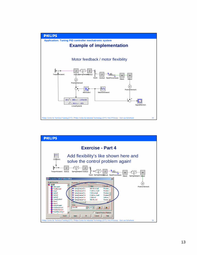
Example of implementationExample of implementation
SignalMonitor1
PPositionSensor1K
1
Attenuate1 WaveGenerator1
PPositionSensor2
100 s2
+ 6880 s + 1.974e+005
s2 + 631.5 s + 1974
LinearSystem1
J
Inertia1SpringDamper1 J
Inertia3m
Mass2
m
Mass1RackPinionGear1
1
i
Gear1
J
Inertia2
T
TorqueActuator1
Motor feedback / motor flexibility
Application: Tuning PID controller mechatronic system
26Philips Centre for Technical Training (CTT) / Philips Centre for Industrial Technology (CFT) / HvU PTGroep – Gert van Schothorst
Exercise Exercise -- Part 4Part 4
J
Inertia1
J
Inertia2
RackPinionGear1
T
TorqueActuator1m
Mass1
m
Mass2
PPositionSensor1
Constant1
SpringDamper1
SpringDamper2 J
Inertia3
1
i
Gear1 SpringDamper3
Add flexibility’s like shown here and solve the control problem again!
14
27Philips Centre for Technical Training (CTT) / Philips Centre for Industrial Technology (CFT) / HvU PTGroep – Gert van Schothorst
SummarySummary
• Modelling a mechatronic system in 20-sim– Sketch (simplified) model– Implement in 20-sim
• Loop shaping / design for performance:– S small where disturbances occur– High bandwidth - small S for low frequency
• Effect of mechatronic system design:– Location of flexibilities– Location of feedback sensors