Embed Size (px)
Citation preview

SATCOM / TELECOM BROCHURE
2013

RADITEK INC.
SATCOM BROCHURE 2013 Specifications may be subject to change 07/10/13 WORLD HQ: 1702L Meridian Ave. Suite 127, San Jose, Ca 95125, U.S.A.
Tel: (408) 266-7404 FAX: (408) 266-4483 WEB: www.raditek.com E-mail: [email protected]
Block Up Converter-L to C Band N or F Type Female Connector, 10MHz Ext Reference, 1mW-500Watts, Outdoor Unit
Block Up Converter-L to C Band N or F Type Female Connector, 10MHz Ext Reference, 1-200Watts, Indoor / Outdoor Unit
Small and Compact 4.9/ 5.15-5.85GHz OFDM outdoor Subscriber 5/10/20/40MHz Fractional Bandwidths, 100Mbps
5GHz OFDM Outdoor Radio 54Mbps Variable Bandwidth
Point to Point Radio Family 2.4 or 5.85GHz
PDH / Ethernet Convergent System 1xE1/T1 and 2xE1/T1
Point to Point Radio Family 6-38GHZ
SSPA Amplifier, Ku-Band (16/25/40/80, 100,150,200)W-
ODU/(Rack), Redundant Ready
Point to Point Radio Family 7-38GHz
Over 300/600 Mbps, Ethernet, Point to Point
Radio
Page 2 of 80

RADITEK INC.
SATCOM BROCHURE 2013 Specifications may be subject to change 07/10/13 WORLD HQ: 1702L Meridian Ave. Suite 127, San Jose, Ca 95125, U.S.A.
Tel: (408) 266-7404 FAX: (408) 266-4483 WEB: www.raditek.com E-mail: [email protected]
This 2013 year of Snake is meant for steady progress and attention to detail. Hoping you achieve all that you set out to create. Good luck to everyone. Raditek is pleased to announce several new Telecommunications products. We can provide the complete solution, to include: Satcom, Point to Point and DAMA products. Plus the last mile solution using Point to Multipoint, IP based solutions, eg WiMax and WiFi. Please come to us with your requirements, we will help you find the best solution.
Our new Satcom Modems increases our Technical lead even more over competitors: 1. RADITEK Micra™, Small form factor (255mm x 184mm) single board modem; With L-band operation IF(950MHz to
2050MHz); Data rates 4.8Kbps to 60Mbps; TCP, IP acceleration, compression, IP routing, bridging, traffic shaping, ACM and throughput diagnostic graphs; DVB-S2, low-latency LDPC and other FEC options up to 64QAM modulation. Now with 5% spectral roll-off factor; 24 Volt (30W) input power supply. An Ideal solution for Man pack and transportable applications.
2. RMOD-DREAM™ has been introduced to support 16Kbps to 12Mbps (TPC) and to 20Mbps (Advanced LDPC) data rates as standard. Ideal tracking modem to work with our IOTM (Internet on the move) antennas. BPSK , QPSK, 8PSK and 16QAM standard
3. RADITEK Extreme™ Multi IF band support: (70M/140MHz and L-band); Data rates 18Kbps to 155Mbps; DVB-S2-/ACM, to 16APSK. LDPC/BCH, TPC FEC options; Terrestrial interface options including Ethernet: EIA-530, G.703 (balanced & unbalanced), OC-3, STM-1, Serial LVDS, ASI, HSSI, Quad E1, Modulation up to 64QAM Simu-Carrier™ option (reusing uplink frequencies); Uplink Power control (AUPC); Signal-under-carrier™ real time interferer detection tool. Plus we have a full range of low to high power BUCs and SSPAs, with LNAs and LNBs.
4. Plus TWTAs (Traveling wave Tube Amplifier) EG: RTWTA-5.850-6.425G-1KW-RL-n6 (right). A C-band, high efficiency, 2.25KW multi-stage depressed collector TWTA. Limited to 1KW maximum LINEAR power with even more efficient power supplies- to give lower cost, better efficiency. The unit includes RF gain control and a solid state pre-amplifier, RF filters, cooling, and monitoring and control (M&C) systems.
5. Plus our NEW, LOW COST, 5.8, 7, 10.5/11, 13 and 23GHz, licensed band, LOW COST, Carrier class, point to point Radios. To 120Mbps, IP and/or up to 60 x E1. EG.: RTR-P2P-13G-60E1+IP120M-LC-g16™
6. We have expanded our last mile radio product range too, in unlicensed bands:2.4GHz and 5.8GHz, for example.
Page 3 of 80

RMOD-DREAM-2IP4 Modem-j8 Specifications may be subject to change 07/09/13 WORLD HQ: 1702L Meridian Ave. Suite 127, San Jose, Ca 95125, U.S.A.
Tel: (408) 266-7404 FAX: (408) 266-4483 WEB: www.raditek.com E-mail: [email protected]
The RADITEK RMOD-DREAM-2IP4 DAMA / SCPC / Router / Satellite Modem is capable of normal, standalone SCPC operation and DAMA/ABOD (Demand Assigned Multiple Access./Adaptive Bandwidth On Demand), router operation. It can realize up to over 95% Satellite efficiency. The RADITEK RMOD-DREAM-2IP4 High Performance, IP Modem is designed for IP networks to 20Mbps/16QAM/LDPC OR to 12Mbps/16QAM/TPC. It is capable for multiple 2-way services and is ideal for all general purpose SCPC operation OR MESH and multi-STAR/MESH DAMA based small to large networks, with carrier rate adaptability to match real time IP traffic.
The DAMA system uses an on-Demand, in-bound, Composite TDM Carrier, using Contention Access, Shared Slotted Aloha (CSC-IB) using only 24/48 Kbps for nitial network entry and to initiate DAMA activation for SCPC / MCPC Inbound Carrier for IP traffic services. The network uses, “Packet Switched Multiple Access”, (PSMA) with Adaptive Bandwidth-On-Demand (ABOD). Applications in MCPC mesh connectivity are particularly suitable for real time traffic such as voice and multicasting videoconference.
When used in the Networking Mode, there are efficient simultaneous links to multiple sites including network hub, remotes, and remote center sites located at end user sites. The ability to connect to two or more central sites allows traffic routing between corporate branches and headquarters directly and traffic bypasses the hub.
DAMA / SCPC / Router /Satellite Modem RMOD-DREAM-2IP4-j8
SATCOM RMOD-DREAM Modem
FEATURES Ideal tracking modem to work with our IOTM (Internet on the move) antennas BPSK , QPSK, 8PSK and 16QAM standard 16Kbps to 12Mbps (TPC) and to 20Mbps (Advanced LDPC) data rates as
standard The modem also has a DVB-S2 receive card option. Has both static and dynamic internet routing to make it an ideal modem for
any internet network applications Ideal for SCADA, Bank ATM, any IP based network, in STAR and/or MESH
configurations. It has the most efficient return channel for DVB-S2/broadband networks.
WEB GUI with traffic statistics
Page 4 of 80

RADITEK INC. code -j8
DAMA / SCPC / Router /Satellite Modem RMOD-DREAM-2IP4-j8
RMOD-DREAM-2IP4 Modem-j8 Specifications may be subject to change 07/09/13 WORLD HQ: 1702L Meridian Ave. Suite 127, San Jose, Ca 95125, U.S.A.
Tel: (408) 266-7404 FAX: (408) 266-4483 WEB: www.raditek.com E-mail: [email protected]
Specifications for RADITEK DREAM-2IP4 DAMA/SCPC/Router/Satellite modem: IP Features and Routing Function Outbound Carrier
Intranet/Internet, Multicast, TCP Acceleration, VLAN, DNS Caching
Proprietary TDM with PSMA, or SCPC/MCPC
Supports standard & Customized QoS traffic Prioritization Protocols: TCP, UDP, RIP, ARP, DHCP, ICMP, IGMP, Telnet, PPP, FTP, HTTP, SMTP, and SNMP
BPSK; QPSK, 8PSK, 16QAM Modulations
Interface Turbo Product Code (TPC) rates: ~1/2, ~3/4, ~7/8 RJ-45, 10/100 Base T Ethernet Interface RS-232 Asynchronous Serial Interface to ACU
LDPC Code rates: 1/2, 2/3, 3/4, 4/5, 8/9
AC Power, IEC-320 Interface 85-264 VAC 47-63Hz, 150W
Carrier Data Rate 16 Kbps to 12 Mbps (TPC) Carrier Data Rate 16 Kbps to 20 Mbps (LDPC)
48VDC @ 2.8A optional 1.20 or 1.30 Symbol Rate Carrier Spacing Options Mechanical Inbound Carrier Dimensions: 43 x 286 x 432 mm Rack Mount Unit SCPC / MCPC with ABOD for IP traffic Weight: 4.0 Kg BPSK, QPSK, 8PSK, 16QAM Modulation Environmental Turbo Product Code: 1/2, 3/4, 7/8 Rates Operating temp.: 0 to +45°Centigrade LDPC Code: 1/2, 2/3, 3/4, 4/5, 8/9 Storage temp.:-30 to +70°Centigrade Inbound Carrier rate adaptable to match actual site traffic Humidity: Up to 95 % non-condensing Spacing Options: 1.20 or 1.30 Symbol Rate Carrier
RECEIVE IF interface TRANSMIT IF Interface Receive: 950-1850 MHz L-band with 2.5 KHz steps; Transmit: 950-1850 MHz L-band with 2.5 KHz steps +24 VDC @ 0.3A and 10 MHz +24 VDC @ 2.7A and 10 MHz Reference @ 5 dBm5 x 10E-8 Reference @ 5dBm/5 x 10E-8 Connector: Type N (f) 75Ω. Connector: Type N (f) 75Ω. Level: -75 to – 35 dBm Level: -45 to -0 dBm in 0.5 dB steps
Option : ESA Embedded Network Spectrum Analyzer Option : HSR High Stability Reference Clock Contact Raditek for your entire C, X, Ku, Ka band BUCs, TRANSCEIVERS, Antennas (tracking/flyaway (Carbon fiber reflector), Manpack and large steerable/trackable antennas, to >16m AND our Internet on the move tracking antennas (Ku band IOTM, as shown on page 1).
Page 5 of 80

RMOD-DVB-S2MOD-80Mbps-p3 Specifications may be subject to change 07/10/13 WORLD HQ: 1702L Meridian Ave. Suite 127, San Jose, Ca 95125, U.S.A.
Tel: (408) 266-7404 FAX: (408) 266-4483 WEB: www.raditek.com E-mail: [email protected]
Features DVB-S2 (EN 302 307) Tx to 45Msps, Rx to 37.5Msps DVB-S2 Constant Coding and Modulation (CCM) DVB-S2 Variable Coding and Modulation (VCM) supporting up to 2 ASI streams optionally multiplexed with IP traffic and IP
M&C DVB-S2 Adaptive Coding and Modulation (ACM) for point-to-point operation DVB-S (EN 300 421), DVB-SNG (EN 301 210) operation to 40Msps IF Frequency range of 50 to 90MHz and 100 to 180MHz
Simu carrier bandwidth re-use
Inner (Forward Error Correction) FEC: Viterbi1, (Trellis Code Modulation) TCM and (Low Density Parity Code) LDPC
Outer FEC options of concatenated (Reed-Solomon) RS and (Bose-Chaudhuri-Hocquenghem) BCH coding.
ASI and Gigabit Ethernet traffic options
Rich IP feature set including routing, bridging, HTTP and TCP Acceleration, Header/Payload Compression, DHCP, IEEE 802.1p QoS, IEEE 802.1q VLAN, traffic shaping and diagnostic graphs. IP over DVB encapsulation supports MPE, ULE and most efficient RADITEK RXE (<2% efficient) standards.
IPv6 compliant
Compact 1U chassis
DVB-S2 Modulator Satellite Modem 80Mbps, RMOD-DVB-S2-80Mbps-p3
SATCOM DVB-S2 Modem
Overview The RMOD-DVB-S2-80Mbps-p3- is an 80Mbps DVB-S2 (Digital Video Broadcast) satellite modulator (also available as a modem). ASI and Gigabit Ethernet interfaces are supported.
Simu carrier Operation
Simu carrier Disabled Simu carrier Enabled (Can save 50% on space segment)
Page 6 of 80

RADITEK INC. code-p3
Digital Video Broadcast satellite RMOD-DVB-S2MOD-80Mbps-p3
RMOD-DVB-S2MOD-80Mbps-p3 Specifications may be subject to change 07/10/13 WORLD HQ: 1702L Meridian Ave. Suite 127, San Jose, Ca 95125, U.S.A.
Tel: (408) 266-7404 FAX: (408) 266-4483 WEB: www.raditek.com E-mail: [email protected]
Main Specifications Frequency (IF) 50 to 90MHz & 100 to 180MHz (resolution 100Hz) (BNC connector) Data Rate DVB-S2: 50kbps to 100Mbps DVB-S/DSNG: 4.8kbps to 100Mbps 1bps resolution Symbol Rate DVB-S2 Tx: 100ksps to 45Msps; DVB-S2 Rx: 100ksps to 37.5Msps; DVB-S/DSNG: 9.6ksps to 40Msps IF port Impedance 50Ω/75Ω IF port Return Loss ~18dB typical Frequency Reference Stability <1ppm/yr External Reference Clocking only: 1 to 10MHz; 1kHz steps Clocking and RF frequency: 10MHz, 0dBm±1dB
Traffic Interfaces Traffic options: Ethernet (10/100/1000 BaseT) IP traffic on RJ45 with processing capability of 50,000 packets per second Quad ASI on 75Ω BNC female
Modulator Output Power 0 to –25dBm (0.1dB steps) Output Power Stability ±0.5dB, 0ºC to 50ºC Transmit Filter Roll-off 20%, 25%, 35% Phase Accuracy <±2º Amplitude Accuracy <±0.2dB Carrier Suppression >-30dBc Output Phase Noise As IESS-316, to 3dB better Harmonics > –55dBc/ 4kHz in band Spurious > –55dBc/ 4kHz in band Transmit On/Off Ratio >55dB Demodulator Input Range Minimum: -115+10 log (symbol rate) Maximum: -80+10 log (symbol rate) Maximum Composite Signal < 20dB above the level of the desired input signal up to a maximum of 0dBm
±1kHz to ±32kHz up to 10 Msps(1kHz steps) Frequency Sweep Width ±10kHz to ±250kHz above 10 Msps (10kHz steps) Acquisition Threshold <5dB Es/No QPSK
Acquisition Time Dependent on FEC, data rate and sweep width, eg: At 9.6kbps, < 1s at 6dB Es/No QPSK; at 10Mbps, < 100ms at 6dB Es/No QPSK.
Clock Tracking Range >±100ppm minimum Receive Filter Roll-off 20%, 25%, 35% Performance Monitoring Eb/No (range 0-15dB, ±0.2dB) Frequency offset (100Hz resolution) Receive signal level Buffer fill status AGC Output Buffered direct AGC output for antenna tracking, etc. Forward Error Correction
DVB-S2: QPSK, 8PSK, 16APSK, 32APSK Modulation DVB-S: QPSK
DVB-DSNG: 8PSK, 16QAM DVB-S2 (LDPC/BCH): QPSK 1/4, 1/3, 2/5, 1/2, 3/5, 2/3, 3/4, 4/5, 5/6, 8/9, 9/10 8PSK 3/5, 2/3, 3/4, 5/6, 8/9, 9/10 16APSK 2/3, 3/4, 4/5, 5/6, 8/9, 9/10 32APSK 3/4, 4/5, 5/6, 8/9, 9/10 (note 32APSK is supported for Tx only) DVB-S: QPSK 1/2, 2/3, 3/4, 5/6 FEC
DVB-DSNG: 8PSK 2/3, 5/6, 8/9; 16QAM 3/4, 7/8
DVB-S2 Performance at PER 1e-6 Guaranteed Es/No (dB) for Short (16k) frames Rate 1/4
Rate 1/3
Rate2/5
Rate1/2
Rate3/5
Rate2/3
Rate3/4
Rate4/5
Rate5/6
Rate 8/9
Rate 9/10
QPSK -1.3 -0.4 0.5 1.9 3.0 3.5 4.4 5.2 5.6 6.7
8PSK 6.5 7.3 8.6 9.9 11.2 11.3
16APSK 9.8 11.1 11.7 12.3 13.5
Page 7 of 80

RADITEK INC. code-p3
Digital Video Broadcast satellite RMOD-DVB-S2MOD-80Mbps-p3
RMOD-DVB-S2MOD-80Mbps-p3 Specifications may be subject to change 07/10/13 WORLD HQ: 1702L Meridian Ave. Suite 127, San Jose, Ca 95125, U.S.A.
Tel: (408) 266-7404 FAX: (408) 266-4483 WEB: www.raditek.com E-mail: [email protected]
DVB-S2 Performance at PER 1e-6 Guaranteed Es/No (dB) for Normal (64k) frames Rate 1/4
Rate 1/3
Rate2/5
Rate1/2
Rate3/5
Rate2/3
Rate3/4
Rate4/5
Rate5/6
Rate 8/9
Rate 9/10
QPSK -1.6 -0.7 0.3 1.5 2.8 3.4 4.3 5.0 5.5 6.5 6.7 8PSK 6.4 7.2 8.6 9.8 11.0 11.3
16APSK 9.7 10.8 11.6 12.2 13.4 13.7
Simu carrier
Simu carrier Transmit and receive carriers use the same frequency/bandwidth. Digital cancellation techniques are used in the demodulator to recover the required receive carrier signal
Simu carrier data rate options: 512kbps, 1024kbps, 2.5Mbps, 5Mbps, 10Mbps, 15Mbps, 20Mbps and 25Mbps traffic rate Allowable power asymmetry: -10dB to +10dB Allowable symbol rate asymmetry: Up to 12:1 Eb/No degradation Typically < 0.5dB (0.7dB for 16QAM/16APSK with up to 10dB power difference)
Mobile Operation: Uses GPS data to continually recalculate position relative to satellite, allowing uninterrupted operation in mobile environments (ships, etc.)
Ruggedization
Ruggedization Option
For modems operating in hostile/harsh environments, the external fan is replaced with two heavy duty fans with greater airflow. Heatsinks are added to critical components to improve dissipation of heat. Improved internal cable assemblies to reduce any problems due to vibration. Internal operating temperature of the modem is lowered by several degrees, so less stress to the electronic components and increased mean time between failure (MTBF).
Ethernet Traffic
Throughput Performance
The maximum modem through-put depends on IP traffic format and the features enabled. Bridged IP/UDP data can be processed up to the modem maximum data rate. Please seek assistance from Raditek to help evaluate your specific requirements.
Routing and Bridging Bridging (standard). Static routing (standard). Dynamic routing option: RIP V1, V2; OSPF V2, V3; BGP V4
TCP Acceleration Option
Typical throughput level of 90% of link capacity. IP Traffic card option: Supports 5,000 concurrent accelerated TCP connection limit (plus at least 35,000 unaccelerated TCP connections) up to the modem maximum data rate. IP Traffic card includes HTTP Acceleration (reduces web page download times)
Header Compression Option
IP Traffic card option. Robust Header Compression to RFC 3095. Reduces Ethernet/IP/UDP/RTP header sizes typically by 90%. 1-way packet processing limit: 60,000 pps; 2-way limit: 45,000 pps. Includes Ethernet header compression (compresses a 14-byte Ethernet frame to typically one byte)
Payload Compression Option
Deflate algorithm (RFC 1951) compresses all TCP/IP packets (TCP and UDP), typically giving a compression of 50%
Traffic Shaping Option Guaranteed throughput levels for IP streams, using Committed Information Rate and Burst Information Rate settingsStream differentiation is by IP address, IEEE 802.1p priority class, Diff serv DSCP class or MPLS EXP field
Encryption Option Encrypts all IP traffic using AES with 256 -bit keys
IPV6 Provided as standard. Dual IPV4/IPV6 TCP/IP stack allowing use of both IPV4 and IPV6 addresses for bridging and routing of traffic IEEE 802.1q VLAN support (standard)
VLAN Support IEEE 802.1p Quality of Service (packet prioritization) using strict priority or fair weighting queuing
DHCP, SNMP DHCP (standard) for automatic allocation of M&C IP address. SNMP (standard) v1, v2c and v3 Web Server Embedded web server M&C interface (standard) IP Diagnostic Graphs Shows Tx, Rx throughput (bps, pps); dropped, packet error counts (standard) Operating mode Can be operated in standalone, 1:1 or 1:N redundancy configuration. IP over DVB Encapsulation Option : Supports encapsulation/decapsulation of MPE, ULE and Raditek (2% overhead) RXE DVB-S2 IP Multi-streaming Point-to-multipoint CCM and VCM multi-streaming. VCM allows the FEC error correction to vary for each remote
DVB-S2 ACM Option Dynamically varies mod-cod with varying link conditions, maximizing throughput at all times by converting excess link margin capacity into additional throughput
Page 8 of 80

RADITEK INC. code-p3
Digital Video Broadcast satellite RMOD-DVB-S2MOD-80Mbps-p3
RMOD-DVB-S2MOD-80Mbps-p3 Specifications may be subject to change 07/10/13 WORLD HQ: 1702L Meridian Ave. Suite 127, San Jose, Ca 95125, U.S.A.
Tel: (408) 266-7404 FAX: (408) 266-4483 WEB: www.raditek.com E-mail: [email protected]
Mechanical/Environmental Size 1U chassis – 410mm deep, excluding front panel handles and rear panel connectors and fans Weight 3.5kg
100-240VAC, +6%, -10%, 1A @100V, 0.5A @ 240V, 47-63Hz Fused IEC connector (live and neutral fused) Power Supply
-48Volts DC option Safety Standards EN60950-1 Emission and Immunity EN55022 Class B (Emissions) EN55024 (Immunity) Operating Temperature 0 to 50ºC Humidity 95% relative humidity, non-condensing Compliance FCC, CE and RoHS compliant Alarm Relays 4 Independent Form C relays for unit, Tx, Rx and backward alarms
Adaptive Coding and Modulation (ACM)
Modulation and coding can automatically and progressively be reduced to recover Eb/No when the link becomes compromised to rain fade etc.
Or by changing the error correction to match worsening atmospheric conditions, link margin is converted into useful bandwidth. Modulation and FEC rate (mod-cod) are dynamically matched to the current Es/No.
The symbol rate is kept constant, changing the terrestrial data rate up or down with Es/No.
Changes in mod-cod are transparent at the receiver, and throughput increases of up to 100% have been reported.
Built in receive spectrum analyzer and receive constellation display for channel diagnostics.
Page 9 of 80

RADITEK INC. code-p3
Digital Video Broadcast satellite RMOD-DVB-S2MOD-80Mbps-p3
RMOD-DVB-S2MOD-80Mbps-p3 Specifications may be subject to change 07/10/13 WORLD HQ: 1702L Meridian Ave. Suite 127, San Jose, Ca 95125, U.S.A.
Tel: (408) 266-7404 FAX: (408) 266-4483 WEB: www.raditek.com E-mail: [email protected]
Description
IF Base Modem description.
With Filter roll-off factors: 20%, 25%, 35% Wideband IF: 50-90 MHz & 100-180MHz in 100Hz steps PID filtering and monitoring Remote web browser based monitoring tools (Spectrum Display, Constellation Monitor and link performance versus time). SMTP email client for status notification SNMP v1, v2c & v3 for modem M&C DHCP allowing IP address to be allocated dynamically via external DHCP network server - DVB options must be selected below :
DVB-S TX Transmit DVB-S compliant (to EN300421) to 40Msymbol/s. QPSK modulation, provides Viterbi FEC Rates 1/2, 2/3, 3/4, 5/6, 7/8 and Reed-Solomon Outer FEC
DVB-S RX Receive DVB-S compliant (to EN300421) to 40Msymbol/s. QPSK modulation, provides Viterbi FEC Rates 1/2, 2/3, 3/4, 5/6, 7/8 and Reed-Solomon Outer FEC
DVB-DSNG TX Transmit DVB-DSNG compliant to EN301210 to 40Msymbol/s. 8PSK and 16QAM modulation Includes DVB-S TX
DVB-DSNG RX Receive DVB-DSNG compliant to EN301210 to 40Msymbol/s. 8PSK and 16QAM modulation Includes DVB-S RX
DVB-S2 CCM TX Transmit DVB-S2 compliant to EN302307 (excluding 32APSK) to 37.5Msymbol/s with Constant Coding and Modulation (CCM) mode Includes DVB-S TX and DVB-DSNG TX
DVB-S2 CCM RX Receive DVB-S2 compliant to EN302307 (excluding 32APSK) to 37.5Msymbol/s with Constant Coding and Modulation (CCM) mode Includes DVB-S RX and DVB-DSNG RX
DVB-S2 VCM Multi-streaming
Variable Coding and Modulation (VCM) allows multiplexing of up to 2 ASI streams with IP traffic and IP M&C onto a single carrier, with per stream selection of modulation, FEC rate, DVB-S2 frame size and pilots
DVB-S2 ACM TX Requires DVB-S2 CCM TX. (Note that ACM RX operation is free of charge subject to the modem having the DVB-S2 CCM RX feature enabled.)
DVB-S2 32APSK Tx To add support for DVB-S2 32APSK to TX (DVB-S2 32APSK for RX is not currently supported) IP Traffic card with Ethernet Bridge and static routing as standard. Includes HTTP Acceleration (by pre-fetching web page inline objects to reduce web page download time). Includes TCP Acceleration up to 16,896kbps Traffic Interface
Hardware Options Quad ASI card. Supports both 188 and 204 byte MPEG2 TS packets. Use of multiple ports is subject to other features purchased
To Add TCP acceleration up to 25Mbps on IP Traffic card - requires IP Traffic card
To dds TCP acceleration up to 55Mbps on IP Traffic card, subject to prevailing data rate limits - requires IP high capacity card and requires 25Mbps acceleration option .
To dds Robust Header Compression to RFC 3095 and RFC 4815 (IP/UDP/RTP), plus RFC 4995 and RFC 4996 (IP/TCP) at throughput rates to 29kpkts/s (1-way), 22kpkts/s (2-way); includes Ethernet header compression - requires IP Traffic card
To add Encapsulation of IP packets and Ethernet frames over DVB uses RADITEK Protocol (RXE), Multi Protocol Encapsulation (MPE) or Ultra Lightweight Encapsulation (ULE) protocols, includes Static Routing - up to 64 static routes
To add Dynamic Routing, supports RIP, OSPF and BGP plus 64 static routes
IP Traffic Card Options
To add IP Traffic Shaping: Supports allocation of CIR and BIR plus priority for IP Streams identified by IP Address, Diff serv Class, IEEE 802.1p priority tag or MPLS EXP field
Quad ASI Card Option To add Multi-stream ASI support, requires DVB-S2 and Quad ASI card
AUPC To add end-to-end AUPC operation only when IP Traffic used - requires TX and RX operation and IP Traffic card Adds self maintain AUPC operation for IP or ASI Traffic - requires TX and RX operation
48V DC Input -48V DC Primary power input in place of 100-240V AC input
FSK Control Option on IF (hardware option)
Allows monitor & control of a compatible Transceiver from the Modem, via the Tx IFL.
Simu carrier Ready, allows Tx and Rx carriers to occupy the same satellite bandwidth. (hardware and S//W option) - requires additional cumulative software options.
Simu carrier Minimum occupied BW limit of 25kHz, and maximum occupied band-width limit of 36MHz .
Ruggedization Adds extra ruggedization for hostile environments
NOTE: Raditek reserves the right to change/improve specifications of features described in this document at any time, without notice and without obligation to notify any person of such changes. Refer to the website or contact Sales or Customer Service for the latest product information.
Page 10 of 80

RMOD-SCPC-(2-20Mb)-70-140M-L-p3 Specifications may be subject to change 07/09/13 WORLD HQ: 1702L Meridian Ave. Suite 127, San Jose, Ca 95125, U.S.A.
Tel: (408) 266-7404 FAX: (408) 266-4483 WEB: www.raditek.com E-mail: [email protected]
OPTIONS Available:
o Data rate is from 2Mbps to a maximum of 20Mbps,
o 10Msymbol/s maximum for 8PSK (and above) and DVB-S2.
o IBS, IDR, E1/E0 Drop & Insert… o DVB-S2 FEC and modulation support…. o Ethernet. o Various traffic/terrestrial interfaces o AUPC (Automatic Uplink Power control) o Quad(4) E1 cards allowing up to 4 x E1s
to be multiplexed onto a single carrier
o IF interfaces include: 70MHz or 140MHz or L-band, and special IF combinations
o SCPC (Single Channel per carrier) o DVB-S2 outbound with SCPC return, or SCPC outbound
with DVB-S2 return. o Or SCPC outbound and return. o Hybrid mode where Tx/Rx SCPC features are combined
with DVB-S2 space segment savings. o All traditional SCPC features are supported including
IBS, IDR, ESC, Drop & Insert, AUPC, etc. o 48 V DC Power Supply
Raditek can also offer other state of the art modems to support SCPC with DAMA, ABOD (automatic bandwidth on demand) with MESH and/or STAR networks-all with sophisticated NMC software support.
The Multi-E1/IP option is a very useful way to combine up to 4x E1 (balanced/G.703) inputs or 3XE1 and an IP input, simultaneously, for transmission on one satellite channel. There is no other way to send IP and E1 at the same time on this modem.
Part Number: RMOD-SCPC-(2-20Mb)*-70/140MHz/L-p3
Description: High Performance Satellite Modem: SCPC 70/140MHz or L-band, 220V AC, IP, E1, T1, Data
* 2Mb (optionally expandable to 20Mbps) data rate,
Options Data Rate DVBS2 Simu Carrier Modulation SCPC LDPC+
If IP is used, an IP accelerator is recommended, either as an option within the modem or a third party external one. The data rate is limited, otherwise, due to the satellite propagation delay.
The maximum data rate when using the MUX option is limited, at any port to 2Mbps. Without any IP accelerator you may not see data rates above 200Kbps on the IP channel.
All E1 MUX options include: Drop and Insert and full E1 setup. Supports Extended Drop and Insert with 1-31 timeslots
Requires IBS/SMS option in 4. the host modem. Modem can easily be 1+1 redundancy protected
Advanced SCPC Satellite Modem 70/140MHz or L-band, 220V AC, IP, E1, T1, Data
RMOD-SCPC-(2-20Mb)*-70/140MHz/L-p3 * 2Mb (optionally expandable to 20Mbps) data rate,
SATCOM SCPC Modem
Up to 4 E1 inputs
TCP-IP input
Page 11 of 80

RADITEK INC. code -p3
Advanced SCPC Satellite Modem 2Mbps (expandable to 20Mbps) data rate, 70 or 140MHz IF, 220V AC.
RMOD-SCPC-2-20Mb-70/140MHz/L-band-p3
RMOD-SCPC-(2-20Mb)-70-140M-L-p3 Specifications may be subject to change 07/09/13 WORLD HQ: 1702L Meridian Ave. Suite 127, San Jose, Ca 95125, U.S.A.
Tel: (408) 266-7404 FAX: (408) 266-4483 WEB: www.raditek.com E-mail: [email protected]
Main Specifications SCPC: BPSK, QPSK, OQPSK, 8PSK (Optionally: 8APSK, 16QAM) Modulation Scheme Or DVB-S2 (Option): QPSK, 8PSK, 16APSK
IF Frequency Range 50 - 90MHz (70MHz) & 100 - 180MHz (140MHz) L-band Frequency Range 950 to 2,050MHz
IF Frequency Resolution 100Hz Traffic Interface - Electrical Ethernet (10/100 BaseT) IP Traffic on RJ45 with link and traffic indicators.
Electronically selectable with other interfaces fitted. Traffic Interface - Options RS422 including X.21 DCE and DTE emulation,
V.35 and RS232 on EIA530 connector 25 pin female D-type (Option), EIA530 maximum 10Mbps, RS232 max 100kbps Serial LVDS 25 pin female D-type (Option) HSSI 50 pin HD SCSI-2 connector (Option) G.703 balanced on EIA530 G.703 unbalanced on BNC female 75Ω Quad E1 G.703 balanced on RJ45 IP Traffic card 10/100/1000 BaseT on RJ45 Mux option allows a mix of multiple G.703 interfaces plus IP and/or EIA530 traffic with a limit of 2,048kbps per MUX traffic to 4 ports max.
User Traffic Data Rate
SCPC: 4.8kbps – 2,048kbps in base Modem DVB-S2 50kbps – 2,048kbps in base Modem, subject to minimum symbol rate of 100ksymbol/s Extension of base operation to 5Mbps (Optionally to 10 and 20Mps)
User Traffic Data Rate Resolution 1bps Note: The combination of FEC Rate, Modulation scheme and Satellite Overhead limits
the Traffic Data Rate Range in all modes.User Data Rate Range – Closed
Network 4.8kbps to 20Mbps no Satellite Overhead (with high Data Rate options)
User Data Rate Range – Minimum Overhead (Closed Network plus
ESC)
As Closed Network above except limits inclusive of overhead of approximately 1.4 times the ESC baud rate. Resolution of 1bps. Supports ESC rate from 110 baud to >38.4kbaud.
Outer Forward Error Correction
Concatenated Intelsat Reed-Solomon Outer Codec to IESS308/310 with Custom Option offering variable code rate. Maximum traffic rate 10Mbps.
Scrambling – SCPC Closed Network Plus ESC
32kbps or above: synchronized to ESC overhead. Less than 32kbps: as per closed network. V.35 Scrambler has CCITT, Intelsat, “FDC” and “Linkabit” modes up to 20Mbps (with high Data Rate options)
IF Connector type BNC female IF Impedance 50Ω & 75Ω, electronically selectable
Return Loss 18dB typical Internal Frequency Reference - Ageing <1ppm/yr
External Reference Clocking Only: 1-10MHz in 1kHz steps. Clocking and RF Frequency: 10MHz, 0dBm±1dB
Page 12 of 80

RADITEK INC. code -p3
Advanced SCPC Satellite Modem 2Mbps (expandable to 20Mbps) data rate, 70 or 140MHz IF, 220V AC.
RMOD-SCPC-2-20Mb-70/140MHz/L-band-p3
RMOD-SCPC-(2-20Mb)-70-140M-L-p3 Specifications may be subject to change 07/09/13 WORLD HQ: 1702L Meridian Ave. Suite 127, San Jose, Ca 95125, U.S.A.
Tel: (408) 266-7404 FAX: (408) 266-4483 WEB: www.raditek.com E-mail: [email protected]
BER Performance -Guaranteed dB (Typical) SCPC mode Rate 1/2 Rate 3/4 Rate 7/8 Rate 2/3 Rate 0.93
1E-4 4.7 (4.4) 6.1 (5.8) 7.1 (6.8) Viterbi QPSK
1E-8 7.2 (6.9) 8.8 (8.5) 9.5 (9.2) 1E-4 4.3 (4.0) 5.4 (5.1) 6.4 (6.1)
Sequential (64kbps) 1E-8 6.4 (6.1) 7.3 (7.0) 8.6 (8.3) 1E-4 5.6 (5.3) 6.1 (5.8) 6.9 (6.6)
Sequential (2048kbps) 1E-8 7.5 (7.2) 8.1 (7.8) 8.4 (8.1) 1E-4 2.7 (2.4) 3.5 (3.2) 4.1 (3.8) 1E-6 6.3 (6.0) Turbo (TPC) QPSK 1E-8 3.3 (3.0) 4.5 (4.2) 4.5 (4.2) 6.8 (6.5) 1E-4 5.6 (5.3) 6.8 (6.5) 1E-6 9.2 (8.9) Turbo (TPC) 8PSK 1E-8 6.8 (6.3) 7.2 (6.8) 9.9 (9.6) 1E-3 6.5 (6.2) 7.7 (7.4) 1E-6 10.0 (9.7) 1E-7 7.8 (7.5) 8.2 (7.8)
Turbo (TPC) 16QAM
1E-8 10.7 (10.4) 1E-3 6.3 (6.0)
8PSK/TCM 1E-8 10.4 (10.1) 1E-4 6.1 (5.8) 8PSK/TCM + Reed-Solomon (all
rates) 1E-10 7.3 (7.0) Modulator Specifications Output Power Level 0 to –25dBm Continuously Variable in 0.1dB steps Output Level Stability ±0.5dB, 0ºC to 40ºC Transmit Filtering Selectable Intelsat IESS and DVB-S2
compliant α = 0.35 α = 0.25 α = 0.20 Occupied Bandwidth 1.2 x Symbol Rate 1.13 x SR 1.1 x SR Recommended Channel Spacing 1.4 x Symbol Rate 1.27 x SR 1.2 x SR Phase Accuracy ±2º maximum Amplitude Accuracy ±0.2dB maximum Carrier Suppression -30dBc minimum Output Phase Noise As IESS-308, nominally 3dB better. Output Frequency Stability <1ppm/yr Harmonics Better than –55dBc/ 4kHz in band Spurious Better than –55dBc/ 4kHz in band Transmit On/Off Ratio 55dB minimum
External Transmit Inhibit By external contact closure or by TTL signal applied to rear panel Alarms & AGC connector
Adaptive Signal Predistorter Option: Use with 16QAM to reduce HPA backoff to 1.6dB. Demodulator Specifications Input Range -30 to –60dBm Maximum Composite Signal 30dB above level to a maximum of 0dBm
Page 13 of 80

RADITEK INC. code -p3
Advanced SCPC Satellite Modem 2Mbps (expandable to 20Mbps) data rate, 70 or 140MHz IF, 220V AC.
RMOD-SCPC-2-20Mb-70/140MHz/L-band-p3
RMOD-SCPC-(2-20Mb)-70-140M-L-p3 Specifications may be subject to change 07/09/13 WORLD HQ: 1702L Meridian Ave. Suite 127, San Jose, Ca 95125, U.S.A.
Tel: (408) 266-7404 FAX: (408) 266-4483 WEB: www.raditek.com E-mail: [email protected]
Demodulator Specifications Frequency Acquisition Range Selectable from ±1kHz to ±32kHz up to 10 MSPS (in 1kHz steps)
±10kHz to ±250kHz above 10 MSPS (in 10kHz steps) Acquisition Threshold <5dB Es/No QPSK Acquisition Time At 9.6kbps, less than 1s at 6dB Es/No QPSK
At 10 Mbps, less than 100ms at 6dB Es/No QPSK Clock Tracking Range ±100ppm minimum Receive Filtering Selectable Intelsat IESS compliant α = 0.35, α = 0.25, α = 0.20 Performance Monitoring Measured Eb/No (range 0-15dB, ±0.2dB). Measured Frequency Offset (100Hz
resolution). Wanted signal level strength indicator centered on the middle of the Rx Input range.
AGC Output Buffered direct AGC output for antenna tracking, etc. Data Rate Specifications
Modulation/FEC FEC Rate de
facto Min Data Rate
(kbps) Max Data Rate (Mbps)
BPSK VIT / SEQ 1/2 4.8 5 / 2 BPSK VIT / SEQ 3/4 7.2 7.5 / 2 BPSK VIT / SEQ 7/8 8.4 8.7 / 2 BPSK VIT RS 1/2 4.3 4.4 BPSK VIT RS 3/4 6.4 6.6 BPSK VIT RS 7/8 7.5 7.7 O/QPSK VIT / SEQ 1/2 9.6 10 / 2 O/QPSK VIT / SEQ 3/4 14.4 15 / 2 O/QPSK VIT / SEQ 7/8 16.8 17.5 / 2 O/QPSK VIT RS 1/2 8.6 8.8 O/QPSK VIT RS 3/4 12.8 13.3 O/QPSK VIT RS 7/8 15 15.5 O/QPSK TPC 1/2 9.6 10 O/QPSK TPC 3/4 14.4 15 O/QPSK TPC 7/8 16.8 17.5 O/QPSK TPC 0.93 17.9 18.6 8PSK TCM 2/3 19.2 20 8PSK TCM RS 2/3 17.7 18.3 8PSK TPC 3/4 21.6 20 8PSK TPC 7/8 25.2 20 8PSK TPC 0.93 26.8 20 16QAM TPC 3/4 28.8 20 16QAM TPC 7/8 33.6 20 16QAM TPC 0.93 35.8 20 Clocking and Buffering Specifications Clock Integrity Frequency Locked Loops give phase-hit immune operation even with poor clock sources such as
routers etc. Internal Standard (±1ppm) External Tracking range ±100ppm/min
Tx Clocking SCPC mode
Rx Clock Slaves Tx timing from Rx clock. (Includes full asymmetric operation)
Page 14 of 80

RADITEK INC. code -p3
Advanced SCPC Satellite Modem 2Mbps (expandable to 20Mbps) data rate, 70 or 140MHz IF, 220V AC.
RMOD-SCPC-2-20Mb-70/140MHz/L-band-p3
RMOD-SCPC-(2-20Mb)-70-140M-L-p3 Specifications may be subject to change 07/09/13 WORLD HQ: 1702L Meridian Ave. Suite 127, San Jose, Ca 95125, U.S.A.
Tel: (408) 266-7404 FAX: (408) 266-4483 WEB: www.raditek.com E-mail: [email protected]
Clocking and Buffering Specifications Buffer Disable Clock from Satellite Tx Input clock Plesiochronous. (Includes full asymmetric operation) Internal Standard ±1ppm External timing clock (DTE interface only)
Rx Clocking SCPC mode
Station Reference (see below) 75Ω BNC female Station Clock Connector, transformer isolated. 1MHz to 10MHz in 1kHz steps (accepts sinusoidal >0dBm or square-wave e.g. G.703 para 10) 120Ω RS422 compatible input, 1MHz to 10MHz in 1kHz steps via Async ESC connector
Station Reference Inputs
NB: When set to 10MHz, the station reference may replace internal reference to all internal circuitry. Unit automatically switches back to internal reference if station reference fails.
Buffer Size Selectable in 1ms increments from 0ms to 99ms. Automatically adjusted to slip an integer number of terrestrial multi-frame lengths for framed rates. Buffer storage: Maximum buffer size – 256kbytes.
Drop & Insert Option Specifications Bearer Types T1-D4, T1-ESF and E1-G.732 Timeslot Selection Independent selection of arbitrary timeslots for both Drop and Insert. Bearer Generation The terrestrial bearer may be looped through the Drop Mux then Insert Mux, or terminated after the
drop Mux and a new blank bearer generated by the insert Mux. The bearer generated within Insert Mux provides full multi-frame and CRC support and may be generated from the Tx clock, station reference, satellite clock or internal reference.
Bearer Backup In the event that Insert Mux bearer clock is lost, or AIS is supplied, then Insert Mux will switch temporarily to bearer generation mode in order to preserve receive traffic. The backup bearer may be generated from the station reference, satellite clock or internal reference.
Terrestrial CRC Fully supported, with front panel display of terrestrial error rate based on CRC (T1-ESF and G.732) or Frame Alignment Word errors (all bearer types).
Timeslot ID The IBS/SMS or Closed Net Plus ESC overhead maintains the identity of individual Drop/Insert timeslots for N=1,2,3,4,5,6,8,10,12,15,16, 20, 24 and 30. (See extended option below).
Extended Drop & Insert Option Specifications Timeslot Re-Ordering Selected timeslots may be independently re-ordered on both Tx and Rx paths. Multi-Destination All or only a subset of the received data may be inserted into the terrestrial bearer on the receive
path for multi-destination working. Timeslot ID Maintenance The IBS/SMS or Closed Net Plus ESC is extended to maintain the identity of individual timeslots for
all values of N from 1 to 31. Signaling Both Channel Associated Signaling (CAS) and Robbed Bit Signaling (RBS) are fully supported. For
G.732 Drop/Insert, CAS signaling is extracted from terrestrial TS16 and carried over the satellite in IBS/SMS TS16 and TS48 before re-inserting into the distant terrestrial TS16. For RBS, the IBS or Closed Net Plus ESC overheads maintain the identity of the in-band signaling and it is re-inserted into the terrestrial multi-frame in the correct positions to maintain the RBS.
Ethernet Traffic Parameter Standard (unaccelerated)
Base modem will pass UDP to at least 5Mbps (subject to prevailing data rate limits enabled in the modem) and unaccelerated TCP to typically 128kbps per connection, subject to an overall packet
Page 15 of 80
RADITEK INC. code -p3
Advanced SCPC Satellite Modem 2Mbps (expandable to 20Mbps) data rate, 70 or 140MHz IF, 220V AC.
RMOD-SCPC-2-20Mb-70/140MHz/L-band-p3
RMOD-SCPC-(2-20Mb)-70-140M-L-p3 Specifications may be subject to change 07/09/13 WORLD HQ: 1702L Meridian Ave. Suite 127, San Jose, Ca 95125, U.S.A.
Tel: (408) 266-7404 FAX: (408) 266-4483 WEB: www.raditek.com E-mail: [email protected]
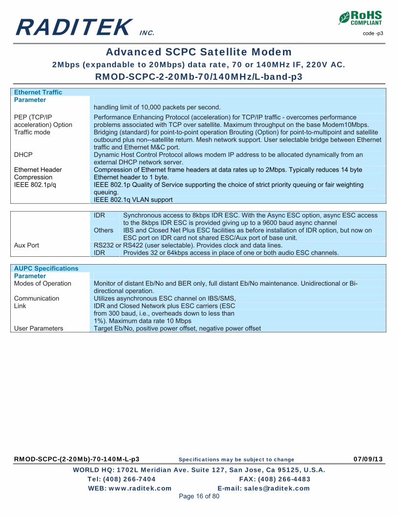
Ethernet Traffic Parameter
handling limit of 10,000 packets per second.
PEP (TCP/IP acceleration) Option
Performance Enhancing Protocol (acceleration) for TCP/IP traffic - overcomes performance problems associated with TCP over satellite. Maximum throughput on the base Modem10Mbps.
Traffic mode Bridging (standard) for point-to-point operation Brouting (Option) for point-to-multipoint and satellite outbound plus non--satellite return. Mesh network support. User selectable bridge between Ethernet traffic and Ethernet M&C port.
DHCP Dynamic Host Control Protocol allows modem IP address to be allocated dynamically from an external DHCP network server.
Ethernet Header Compression
Compression of Ethernet frame headers at data rates up to 2Mbps. Typically reduces 14 byte Ethernet header to 1 byte. IEEE 802.1p Quality of Service supporting the choice of strict priority queuing or fair weighting queuing.
IEEE 802.1p/q
IEEE 802.1q VLAN support
IDR Synchronous access to 8kbps IDR ESC. With the Async ESC option, async ESC access to the 8kbps IDR ESC is provided giving up to a 9600 baud async channel
Others IBS and Closed Net Plus ESC facilities as before installation of IDR option, but now on ESC port on IDR card not shared ESC/Aux port of base unit.
RS232 or RS422 (user selectable). Provides clock and data lines. Aux Port IDR Provides 32 or 64kbps access in place of one or both audio ESC channels.
AUPC Specifications Parameter Modes of Operation Monitor of distant Eb/No and BER only, full distant Eb/No maintenance. Unidirectional or Bi-
directional operation. Communication Utilizes asynchronous ESC channel on IBS/SMS, Link IDR and Closed Network plus ESC carriers (ESC from 300 baud, i.e., overheads down to less than 1%). Maximum data rate 10 Mbps User Parameters Target Eb/No, positive power offset, negative power offset
Page 16 of 80

RADITEK INC. code -p3
Advanced SCPC Satellite Modem 2Mbps (expandable to 20Mbps) data rate, 70 or 140MHz IF, 220V AC.
RMOD-SCPC-2-20Mb-70/140MHz/L-band-p3
RMOD-SCPC-(2-20Mb)-70-140M-L-p3 Specifications may be subject to change 07/09/13 WORLD HQ: 1702L Meridian Ave. Suite 127, San Jose, Ca 95125, U.S.A.
Tel: (408) 266-7404 FAX: (408) 266-4483 WEB: www.raditek.com E-mail: [email protected]
BERT Tester Option Specifications BER Channel The BERT may operate through main traffic, ESC or Aux data channels, or outputted via the
terrestrial interface. Use of ESC & Aux data channels allows continuous real traffic BER performance monitoring whilst the modem carries traffic.
Test Patterns PRBS 2^N-1: N=6, 7, 9, 11, 15, 19, 20, 23. All 1s, All 0s, Alternate Patterns, Sparce Patterns, QRSS, User. Compatible with common stand-alone BER
testers. Results Display of error count and average BER. Autolog Automatic logging of average BER and other parameters at regular intervals. General Specifications Loop-backs Interface Loop (Local and Remote) Framer Loop (Local) RS Loop (Local) FEC Loop (Local)
Deframer/Framer Loop (Remote) Internal IF loopback (local, automatically matching Rx IF frequency to Tx)
Test Modes Transmit CW (Pure Carrier) Transmit Alternate 1-0 Pattern Wideband spectrum analyzer display EZ Audio: 1kHz test tone on audio channels in IDR and P1348 emulation modes Alarm Relays 4 Independent Change-Over Contacts: Unit Fault, Rx Traffic Fault Tx Traffic Fault, Deferred Alarm (backward alarm, BER or Eb/No below user set threshold) Controller Motorola PowerPC Embedded Software Revised embedded software may be downloaded into FLASH memory via Ethernet port with
modem remaining in equipment rack. Configuration Memories >20 configurations can be stored and recalled from the front panel or remote M&C. Memories can
be labeled with text string to aid identification. User Interface Clear and intuitive operator interface with plain English dialogue (other languages supported).
Graphic display, backlit, high contrast, wide angle LCD. 17 key tactile full keyboard. Remote Monitor And Control
For multi-drop applications, RS485 interface. For direct to PC applications, RS232 interface (front panel selectable). M&C port may be directly internally linked to ESC port for “over-the-satellite” M&C without cabling. Ethernet (10/100 Base T) via RJ45, embedded Web server, SNMP agent V1, V2c and V3
Redundancy Features 1:1 redundancy controller built in. “Y” cables passively split data maintaining impedances. IF inputs/outputs are passively split/ combined outside the units. Off-line unit tri-states data outputs and mutes Tx carrier.
Monitor 0-10V analogue output (Signal level, Eb/No, or Rx offset frequency) on Alarms & AGC connector. Mechanical 1U chassis – 410mm deep, excluding front panel handles and rear panel connectors and fans. Weight 3.5 kg Power Supply 100-240VAC, +6%, -10%, 1A @100V, 0.5A @ 240V, 47-63Hz. Fused IEC connector (live and neutral fused). 48 Volts DC option Safety EN60950-1 EMC EN55022 Class B (Emissions) EN55082 Part 1 (Immunity) Environmental Operating Temperature Range 0-50ºC
Page 17 of 80

RADITEK INC. code -p3
Advanced SCPC Satellite Modem 2Mbps (expandable to 20Mbps) data rate, 70 or 140MHz IF, 220V AC.
RMOD-SCPC-2-20Mb-70/140MHz/L-band-p3
RMOD-SCPC-(2-20Mb)-70-140M-L-p3 Specifications may be subject to change 07/09/13 WORLD HQ: 1702L Meridian Ave. Suite 127, San Jose, Ca 95125, U.S.A.
Tel: (408) 266-7404 FAX: (408) 266-4483 WEB: www.raditek.com E-mail: [email protected]
ODU facilities via IF interface Parameter FSK Control Option Allows monitor & control of a compatible Transceiver from the Modem, via the Tx IFL. A single composite datastream carrying diverse traffic and traffic formats requires just one modem at each site for a point-to-point link — reducing modem count with no reduction in flexibility.
An RF power amplifier carrying a single carrier may be operated closer to saturation than an amplifier carrying multiple carriers — e.g. an SSPA with 2 x carriers must be backed off by 2.5dB more than a single carrier SSPA system (TWTAs require even more back-off!). An SSPA with 3 x carriers requires 3.5dB back-off. The single carrier benefit results in more useable power from a given RF amplifier, therefore requires a smaller RF amplifier than multi-carrier solutions.
As a result of the above, both hub and remote costs are reduced — results in more cost effective solutions for complex systems.
1:1 Redundancy protection is available on the combined Modem offers improved reliability for both the modem and multiplexer functions and the 1:1 redundancy controller is included free of charge in the modems.
More services can be carried simultaneously with no increase in system complexity expandable through software activated feature codes.
Less hardware means smaller equipment size and less weight — makes the Modem ideal for transportable and mobile systems.
Suitable for both Military and Commercial applications - has uses in GSM over Satellite (particularly during migration to IP traffic), Distance Learning, Outside Broadcast Co-ordination, Disaster Recovery and more.
Offers more services to the user at minimal extra cost - multiple traffic links are concentrated into a single carrier.
Page 18 of 80

RADITEK INC. code -p3
Advanced SCPC Satellite Modem 2Mbps (expandable to 20Mbps) data rate, 70 or 140MHz IF, 220V AC.
RMOD-SCPC-2-20Mb-70/140MHz/L-band-p3
RMOD-SCPC-(2-20Mb)-70-140M-L-p3 Specifications may be subject to change 07/09/13 WORLD HQ: 1702L Meridian Ave. Suite 127, San Jose, Ca 95125, U.S.A.
Tel: (408) 266-7404 FAX: (408) 266-4483 WEB: www.raditek.com E-mail: [email protected]
E1 DATA-MUX option for RMOD-SCPC-5-20Mbps-70MHz-p3 Example
The E1 MUX DATA option is a feature, which is available with 70/140MHz IF or L-band interfaces, and the entire Modem family includes free monitoring tools such as a Spectrum Analyzer, Constellation Monitor, performance graphing versus time up to 1 month in duration, plus full Monitor & Control via Internet Explorer and offers unique features which are both cost effective and easy to use. Application Examples - GSM, Hybrid Services, Cost/Carrier-Reduction
GSM over satellite migration from G.703 telephony to IP traffic GSM over satellite mixed G.703 plus IP data services Mixed G.703 and VoIP telephony streams
E1MUX Data Option
Page 19 of 80
RMOD-EXTREME-p3 Specifications may be subject to change 07/08/13 WORLD HQ: 1702L Meridian Ave. Suite 127, San Jose, Ca 95125, U.S.A.
Tel: (408) 266-7404 FAX: (408) 266-4483 WEB: www.raditek.com E-mail: [email protected]
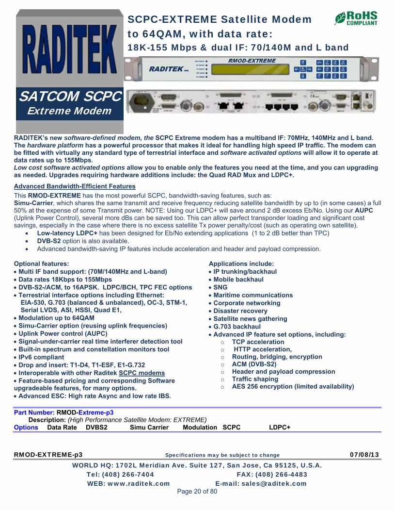
RADITEK’s new software-defined modem, the SCPC Extreme modem has a multiband IF: 70MHz, 140MHz and L band. The hardware platform has a powerful processor that makes it ideal for handling high speed IP traffic. The modem can be fitted with virtually any standard type of terrestrial interface and software activated options will allow it to operate at data rates up to 155Mbps. Low cost software activated options allow you to enable only the features you need at the time, and you can upgrading as needed. Upgrades requiring hardware additions include: the Quad RAD Mux and LDPC+.
Advanced Bandwidth-Efficient Features
This RMOD-EXTREME has the most powerful SCPC, bandwidth-saving features, such as: Simu-Carrier, which shares the same transmit and receive frequency reducing satellite bandwidth by up to (in some cases) a full 50% at the expense of some Transmit power. NOTE: Using our LDPC+ will save around 2 dB excess Eb/No. Using our AUPC (Uplink Power Control), several more dBs can be saved too. This can allow perfect transponder loading and significant cost savings, especially in the case where there is no excess satellite Tx power penalty/cost (such as operating own satellite).
Low-latency LDPC+ has been designed for Eb/No extending applications (1 to 2 dB better than TPC) DVB-S2 option is also available. Advanced bandwidth-saving IP features include acceleration and header and payload compression.
Optional features: Multi IF band support: (70M/140MHz and L-band) Data rates 18Kbps to 155Mbps DVB-S2-/ACM, to 16APSK. LDPC/BCH, TPC FEC options Terrestrial interface options including Ethernet:
EIA-530, G.703 (balanced & unbalanced), OC-3, STM-1, Serial LVDS, ASI, HSSI, Quad E1,
Modulation up to 64QAM Simu-Carrier option (reusing uplink frequencies) Uplink Power control (AUPC) Signal-under-carrier real time interferer detection tool Built-in spectrum and constellation monitors tool IPv6 compliant Drop and insert: T1-D4, T1-ESF, E1-G.732 Interoperable with other Raditek SCPC modems Feature-based pricing and corresponding Software upgradeable features, for many options. Advanced ESC: High rate Async and low rate IBS.
Applications include: IP trunking/backhaul Mobile backhaul SNG Maritime communications Corporate networking Disaster recovery Satellite news gathering G.703 backhaul Advanced IP feature set options, including:
o TCP acceleration o HTTP acceleration, o Routing, bridging, encryption o ACM (DVB-S2) o Header and payload compression o Traffic shaping o AES 256 encryption (limited availability)
Part Number: RMOD-Extreme-p3 Description: (High Performance Satellite Modem: EXTREME) Options Data Rate DVBS2 Simu Carrier Modulation SCPC LDPC+
SCPC-EXTREME Satellite Modem to 64QAM, with data rate: 18K-155 Mbps & dual IF: 70/140M and L band
SATCOM SCPC Extreme Modem
Page 20 of 80

RADITEK INC. code-p3
SCPC Satcom Modem (18K-155 Mbps), (IFs: 70, 140MHz & L band), BPSK to 64QAM, RMOD-EXTREME-p3
RMOD-EXTREME-p3 Specifications may be subject to change 07/08/13 WORLD HQ: 1702L Meridian Ave. Suite 127, San Jose, Ca 95125, U.S.A.
Tel: (408) 266-7404 FAX: (408) 266-4483 WEB: www.raditek.com E-mail: [email protected]
Specifications
Frequency
IF: 50 to 90MHz & 100 to 180MHz (resolution 100Hz) (BNC f/m connector) L-band: 950 to 2050MHz (resolution 100Hz) (N-type f/m connector)
Data Rate
DVB-S2: 50kbps to 155Mbps LDPC+: 4.8kbps to 100Mbps TPC: 4.8kbps to 60Mbps 1bps resolution Operation to 2,048kbps-standard. Options to 5Mbps, 10Mbps, 25Mbps, 60Mbps, 100Mbps and 155Mbps
Symbol Rate DVB-S2: 100ksps to 45Msps Non-DVB-S2: 9.6ksps to 40Msps
Operating Modes
DVB-S2 (EN 302 307) option Closed Network (+ ESC) (IESS-315) IBS/IDR (IESS-308/309/310/314) options
Scrambling
DVB-S2: as per EN 302 307 IBS: Synchronized to framing per IESS-309 Closed Network + ESC: Synchronized to ESC overhead
Impedance IF: 50Ω/75Ω L-band: 50Ω
Return Loss IF: 18dB typical L-band: 14dB typical
Frequency Reference Stability
Ageing <4E-8/yr
External Reference
Clocking only: 1 to 10MHz, 1kHz steps Clocking and RF frequency: 10MHz, 0dBm±1dB
Redundancy Standalone, 1:1 or 1:N redundancy configuration Traffic Interfaces Base modem (standard): Ethernet (10/100/1000 BaseT) IP traffic on RJ45. Processing capability: 100,000 packets per second Traffic options: EIA-530 (RS422, X.21, V.35 and RS232 on 25-pin D-type female) G.703 (balanced on RJ-45; unbalanced 75Ω BNC female) Quad E1 G.703 (balanced RJ45) Quad ASI (75Ω BNC) STM-1/OC-3/Optical Gigabit Ethernet (small form-factor pluggable module) Serial LVDS (25-pin D-type female), HSSI 50pin HD SCSI-2 connector (50-pin f/m D connector) RadMux (4 port Mux) option: Combines from: G.703, IP and EIA-530 traffic (requires Quad E1 option)
Modulator
Output Power IF: 0 to –25dBm (0.1dB steps) L-band: 0 to –30dBm (0.1dB steps)
Output Power Stability ±0.5dB, 0ºC to 50ºC Transmit Filter Roll-off 5, 10, 15, 20%, 25%, 35% Phase Accuracy ±2º maximum Amplitude Accuracy ±0.2dB maximum Carrier Suppression -30dBc minimum Output Phase Noise To IESS-316, typ. 3dB better Harmonics Better than –55dBc/ 4kHz in band Spurious Better than –55dBc/ 4kHz in band Transmit On/Off Ratio 55dB minimum Demodulator
Input Range
IF minimum: -115+10 log (symbol rate) L-band minimum: -130+10 log (symbol rate) IF/L-band maximum: -80+10 log (symbol rate)
Maximum Composite Signal
+10dBm
Wanted-to-composite Level
IF: -94+10 log (symbol rate) L-band: -102+10 log (symbol rate)
Frequency Sweep Width
±1kHz to ±32kHz up to 10 Msps (1kHz steps) ±10kHz to ±250kHz above 10 Msps (10kHz steps)
Acquisition Threshold <5dB Es/No QPSK
Acquisition Time
Dependent on FEC, data rate and sweep width (at 9.6kbps, less than 1s at 6dB Es/No QPSK; at 10Mbps, less than 100ms at 6dB Es/No QPSK)
Clock Tracking Range ±100ppm minimum Receive Filter Roll-off 5, 10, 15, 20%, 25%, 35%
Performance Monitoring
Eb/No (range 0-15dB, ±0.2dB) Frequency offset (100Hz resolution) Receive signal level Buffer fill status
AGC Output Buffered direct AGC output for antenna tracking, etc.
Page 21 of 80

RADITEK INC. code-p3
SCPC Satcom Modem (18K-155 Mbps), (IFs: 70, 140MHz & L band), BPSK to 64QAM, RMOD-EXTREME-p3
RMOD-EXTREME-p3 Specifications may be subject to change 07/08/13 WORLD HQ: 1702L Meridian Ave. Suite 127, San Jose, Ca 95125, U.S.A.
Tel: (408) 266-7404 FAX: (408) 266-4483 WEB: www.raditek.com E-mail: [email protected]
Forward Error Correction
Modulation
1. DVB-S2 (Option): QPSK, 8PSK, 16APSK 2a. Non-DVB-S2: BPSK, QPSK, OQPSK 2b. Plus options for: 8PSK, 16QAM, 2c. Low Latency LDPC+: 8QAM, 16APSK, 32APSK, 64QAM
FEC
1. DVB-S2 (LDPC/BCH) option: QPSK: 1/4, 1/3, 2/5, 1/2, 3/5, 2/3, 3/4, 4/5, 5/6, 8/9, 9/10 8PSK: 3/5, 2/3, 3/4, 5/6, 8/9, 9/10 16APSK: 2/3, 3/4, 4/5, 5/6, 8/9, 9/10 2. Non-DVB-S2: Note BPSK and (O)QPSK provided as standard; other modulations are optional: 3. Low-Latency LDPC+ option: BPSK: 0.499 (O)QPSK: 0.532, 0.639, 0.710, 0.798 8PSK/8QAM: 0.639, 0.710, 0.778 16APSK/16QAM: 0.726, 0.778, 0.828, 0.851 32APSK: 0.778, 0.828, 0.886, 0.938 64QAM: 0.828, 0.886, 0.938, 0.960 4. TPC option: BPSK: 5/16, 21/44, 2/3, 3/4, 0.493, 7/8, Rate 7/8 de facto, 0.789, (O)QPSK: 5/16, 21/44, 2/3, 3/4, 0.493 7/8, 7/8 de facto, 0.789, 0.93 8PSK: 3/4 de facto, 7/8 de facto, 0.93 16QAM: 3/4 de facto, 7/8 de facto, 0.93 5. Viterbi: BPSK/(O)QPSK 1/2, 3/4, 7/8 6. TCM option: 8PSK rate:2/3 7. Sequential option: BPSK/(O)QPSK 1/2, 3/4, 7/8 8. Reed-Solomon: Outer codec available with Viterbi and TCM
Ethernet Traffic
Throughput Performance
The maximum modem throughput depends on IP traffic format and the features enabled. Bridged IP/ UDP data can be processed up to the modem maximum data rate. Please seek assistance in evaluating your particular requirements.
Routing and Bridging
Bridging (standard).Static routing (standard). Dynamic routing option: RIP V1, V2; OSPF V2, V3; BGP V4
TCP Acceleration Typical throughput level of 90% of link
Option capacity. Supports 5,000 concurrent accelerated TCP connections (plus at least 35,000 unaccelerated TCP connections) up to the modem maximum data rate.
Header Compression Option
Header Compression to RFC 3095. Reduces Ethernet/IP/UDP/ TCP/RTP header sizes typically by 90%. 1-way packet processing limit: 60,000 pps; 2-way limit: 45,000 pps. Includes Ethernet header compression (compresses 14-byte Ethernet frame to typically one byte)
Payload Compression Option
Uses Deflate algorithm (RFC 1951) to compress all TCP/IP packets (TCP and UDP), typically resulting in compression of payloads by 50%
Traffic Shaping Option
Reliable throughput levels for IP streams, using committed info. rate and Burst Info. Rate settings. Stream differentiation is by IP address, IEEE 802.1p priority class, Diff serv DSCP class or MPLS EXP field
Encryption Option Encrypts all IP traffic using AES with 256-bit keys
IPv6
Provided as standard. Dual IPV4/ IPV6 TCP/IP stack allowing use of both IPv4 and IPv6 addresses for bridging and routing of traffic
VLAN Support
IEEE 802.1q VLAN support (standard) IEEE 802.1p Quality of Service (packet prioritization) using strict priority or fair weighting queuing
DHCP, SNMP DHCP (standard) for automatic allocation of M&C IP address. SNMP (standard) v1, v2c and v3
Web Server Embedded web server M&C interface (standard)
IP Diagnostic Graphs Shows Tx, Rx throughput (bps, pps); dropped, errored packet counts (standard)
IP over DVB-S2 Encapsulation Option
Supports encapsulation/ decapsulation of MPE (EN301192), ULE (RFC4326) Or RADITEK’s advanced RXE
DVB-S2 ACM (option)
Dynamically varies mod/cod with varying link conditions, maximizing throughput at all times by converting unused link margin into additional throughput
Page 22 of 80

RADITEK INC. code-p3
SCPC Satcom Modem (18K-155 Mbps), (IFs: 70, 140MHz & L band), BPSK to 64QAM, RMOD-EXTREME-p3
RMOD-EXTREME-p3 Specifications may be subject to change 07/08/13 WORLD HQ: 1702L Meridian Ave. Suite 127, San Jose, Ca 95125, U.S.A.
Tel: (408) 266-7404 FAX: (408) 266-4483 WEB: www.raditek.com E-mail: [email protected]
ODU facilities via IF interface
FSK Control Allows monitor & control of a compatible L-band BUC or IF Transceiver from the modem via the Tx IFL cable
Simu-Carrier
Simu-Carrier
Transmit and receive carriers share/reuse the same bandwidths. Special digital techniques are used in the demodulator to cancel the transmit carrier leaving the receive carrier signal.
Simu-Carrier data rate options
256kbps, 512kbps, 1024kbps, 2.5Mbps, 5Mbps, 10Mbps, 15Mbps, 20Mbps, 25Mbps, 30Mbps, 40Mbps, 50Mbps, 60Mbps, 80Mbps, 100Mbps and 155Mbps traffic rate (30kHz to 54MHz occupied bandwidth)
Power asymmetry -10dB to +10dB Symbol rate asymmetry
Up to 12:1
Eb/No degradation Typically < 0.5dB (0.7dB for 16QAM/16APSK with 10dB power asymmetry)
Mobile Operation
Uses GPS data to continually update the position allowing uninterrupted operation in mobile environments (ships, etc.) anywhere in the satellite footprints.
Drop & Insert Option Bearer Types T1-D4, T1-ESF, E1-G.732 Timeslot Selection Independent selection of arbitrary timeslots
for both drop and insert. Bearer Generation Terrestrial bearer may be looped through
modem, or terminated after Drop Mux and a new bearer generated by the insert Mux
Timeslot ID Maintains the identity of individual Drop/Insert timeslots for N=1,2,3,4,5,6,8,10,12,15,16, 20, 24 and 30. (See extended option-next)
Extended Drop & Insert Option
Multi-Destinational Working
All or only a subset of the received data may be inserted into the terrestrial bearer on the receive path for multi-destination working
Timeslot ID Maintenance
Maintains the identity of individual timeslots for all values of N from 1 to 31
Signaling CAS and RBS are fully supported
Advanced ESC
ESC/Aux Port Provides high-rate async ESC or Intelsat low-rate async IBS ESC
Electrical Interface
IP, RS232, RS422 or RS485
Async ESC Closed Net Plus ESC
Overhead scales to any ESC baud rate from 0.5% to 70% of the main channel rate
Async ESC IBS Option
High-rate async channel (1/32nd to 2/32nd of the IBS overhead) providing async baud rates from 0.2% to 5.1% of the terrestrial rate
Advanced Aux
Intelsat low-rate async ESC carried in bit 1 of TS32 providing a synchronous channel at 1/480th of the data rate, allowing up to one quarter of this rate for over-sampled async data
Page 23 of 80

RADITEK INC. code-p3
SCPC Satcom Modem (18K-155 Mbps), (IFs: 70, 140MHz & L band), BPSK to 64QAM, RMOD-EXTREME-p3
RMOD-EXTREME-p3 Specifications may be subject to change 07/08/13 WORLD HQ: 1702L Meridian Ave. Suite 127, San Jose, Ca 95125, U.S.A.
Tel: (408) 266-7404 FAX: (408) 266-4483 WEB: www.raditek.com E-mail: [email protected]
DVB-S2 Performance at BER 1E-6 Guaranteed Es/No (dB) for Normal (64k) Frames
Rate 1/4
Rate 1/3
Rate 2/5
Rate 1/2
Rate 3/5
Rate 2/3
Rate 3/4
Rate 4/5
Rate 5/6
Rate 8/9
Rate 9/10
QPSK -1.6 -0.7 0.3 1.5 2.8 3.4 4.3 5.0 5.5 6.5 6.7 8PSK 6.4 7.2 8.5 9.8 11.0 11.3 16APSK 9.7 10.8 11.6 12.2 13.4 13.7
DVB-S2 Performance at BER 1E-6 Guaranteed Es/No (dB) for Short (16k) Frames
Rate 1/4
Rate 1/3
Rate 2/5
Rate 1/2
Rate 3/5
Rate 2/3
Rate 3/4
Rate 4/5
Rate 5/6
Rate 8/9
Rate 9/10
QPSK -1.3 -0.4 0.5 1.9 3.0 3.5 4.4 5.2 5.6 6.7 8PSK 6.5 7.3 8.6 9.9 11.2 11.3 16APSK 9.8 11.1 11.7 12.3 13.5
Guaranteed Eb/No BER Performance (dB) (Typical in parentheses)
Rate 1/2
Rate 3/4
Rate 7/8
Rate 2/3
Rate 0.93
1E-4 4 4.7 (4.4) 6.1 (5.8) 7.1 (6.8) Viterbi QPSK
1E-8 7.2 (6.9 8.8 (8.5) 9.5 (9.2) 1E-4 4.3 (4.0) 5.4 (5.1) 6.4 (6.1) Sequential
(64kbps) 1E-8 6.4 (6.1) 7.3 (7.0) 8.6 (8.3) 1E-4 5.6 (5.3) 6.1 (5.8) 6.9 (6.6) Sequential
(2048kbps) 1E-8 7.5 (7.2) 8.1 (7.8) 8.4 (8.1) 1E-4 2.7 (2.4) 3.5 (3.2) 4.1 (3.8) 1E-6 6.3 (6.0) Turbo (TPC)
QPSK 1E-8 3.3 (3.0) 4.5 (4.2) 4.5 (4.2) 6.8 (6.5) 1E-4 5.6 (5.3) 6.8 (6.5) 1E-6 9.2 (8.9)
2Turbo (TPC) 8PSK
1E-8 6.8 (6.3) 7.2 (6.8) 9.9 (9.6) 1E-3 6.5 (6.2) 7.7 (7.4) 1E-6 10.0 (9.7) 1E-7 7.8 (7.5) 8.2 (7.8) Turbo (TPC)
16QAM
1E-8 10.7 (10.4)
1E-3 6.3 (6.0) 8PSK/TCM
1E-6 10.4 (10.1) 1E-4 6.1 (5.8) 8PSK/TCM +
Reed-Solomon (all rates) 1E-10 7.3 (7.0)
Page 24 of 80

RADITEK INC. code-p3
SCPC Satcom Modem (18K-155 Mbps), (IFs: 70, 140MHz & L band), BPSK to 64QAM, RMOD-EXTREME-p3
RMOD-EXTREME-p3 Specifications may be subject to change 07/08/13 WORLD HQ: 1702L Meridian Ave. Suite 127, San Jose, Ca 95125, U.S.A.
Tel: (408) 266-7404 FAX: (408) 266-4483 WEB: www.raditek.com E-mail: [email protected]
Mechanical Environmental
Size 1U chassis, 410mm deep excluding front panel handles and rear panel connectors and fans
Weight 3.5kg Power Supply 90-250VAC, 1A @100V, 0.5A @ 240V,
47-63Hz Fused IEC connector (live and neutral fused); 48V DC optional
Safety Standards EN60950-1 2006 Emission and Immunity
EN55022 2006 Class B (Emissions) EN55024 1998 A1 + A2 (Immunity)
Operating Temperature
0 to 50ºC
Compliance FCC, CE and RoHS compliant Humidity 95% relative humidity, non-condensing Alarm Relays 4 Independent Form C relays for unit,
Tx, Rx and backward alarms
Carrier Under Carrier, interference monitoring plots, showing an interferer, in real time, that is invisible to a regular Spectrum analyzer, when the data traffic is running. Eb/No degradation is optionally programmable, to alarm at a preset level. How does the RMOD-EXTREME-p3 compare to others?
Built-in Spectrum Analyser showing Signal-Under-Carrier interference detection without/with interferer present.
without/with interferer present
BER Testing Option
BER Channel Bit error rate tester operates over main traffic, ESC or Aux channels, allowing BER monitoring while on traffic. Not available in DVB-S2 mode
Test Patterns Various test patterns compatible with common BER testers
Other test modes Transmit CW (pure carrier) Transmit alternate 1-0 pattern Simulated satellite delay for TCP/IP packets
IF cable power (and reference) summary LNB reference 10M ±0.001ppm, 0dBm ±3 dB LNB power 15V or 24V 0.5A BUC power 24 or 48V, 200W
Page 25 of 80

RADITEK INC. code-p3
SCPC Satcom Modem (18K-155 Mbps), (IFs: 70, 140MHz & L band), BPSK to 64QAM, RMOD-EXTREME-p3
RMOD-EXTREME-p3 Specifications may be subject to change 07/08/13 WORLD HQ: 1702L Meridian Ave. Suite 127, San Jose, Ca 95125, U.S.A.
Tel: (408) 266-7404 FAX: (408) 266-4483 WEB: www.raditek.com E-mail: [email protected]
Regarding the Comtech CDM625, for example, EDMAC is a COMTECH ESC channel proprietary command protocol. RADITEK modems do not support EDMAC, per se, but we do have equivalent ESC command protocols. Some highlights for the RMOD-EXTREME-p3 include: · Data rates from 18kbps to 10Mbps ( up to 155Mbps). · Modulations from BPSK to 16QAM (but also 16APSK, 32APSK and 64QAM). · The equivalent ESC channel control to EDMAC/EDMAC 2. · Drop & Insert for Single port E1/T1 and Quad E1 D and I (Ports 2, 3, 4). · The modem hardware itself supports IEEE 1588v2 Precision Time Protocol (PTP) and we are in the process of updating/adding software support for this feature. · Support for jumbo Ethernet frames (2048 byte). · We have no direct equivalent of Comtech’s CnC-APC, but do support AUPC(Adaptive Uplink Power Control) with SIMU-Carrier. · Note: We do not support asynchronous E1 streams because, as stated, G.703 actually requires that clocks are synchronous to within +/-50ppm at 2048kbps so there is no actual market, or significant market, that we are aware of for asynchronous timing support?? · SNMP can be used to reboot the modem, if necessary, and can be used for 1:N control. · The modem supports Robbed-bit Signaling. · Quality of Service (QoS) supports Layer 2 and Layer 3. The RADITEK modem that matches (and exceeds) the CDM625 is the new 155Mbps Raditek Extreme. . Essentially the CDM625 doesn’t even support standard 20% roll-off (managing only 25% minimum) compared to the 5% roll-off for the Extreme.
Comtech Comtech Paradise RADITEK RADITEK Comments Model: CDM625 CDM750 PD60 Extreme
Carrier overlap √ √ √ √ Carrier overlap + power control
√ × × × Have SIMU-Carrier and AUPC instead
5% spectral roll-off factor × × √ √
Low-latency LDPC √ × √ √
Low-latency ACM √ × × × Under development
Header compression √ × √ √
Payload compression √ √ √ √
Encryption √ × × √
Acceleration × × √ √
Traffic shaping √ × √ √
Dual IF/L-band √ √ × √
Maximum data rate 25Mbps 169Mbps 100Mbps 155Mbps Maximum symbol rate 12.5Msps 63Msps 40Msps 45Msps
Model:
Comtech
Comtech
Paradise
RADITEK
RADITEK Comments:
Page 26 of 80

RADITEK INC. code-p3
SCPC Satcom Modem (18K-155 Mbps), (IFs: 70, 140MHz & L band), BPSK to 64QAM, RMOD-EXTREME-p3
RMOD-EXTREME-p3 Specifications may be subject to change 07/08/13 WORLD HQ: 1702L Meridian Ave. Suite 127, San Jose, Ca 95125, U.S.A.
Tel: (408) 266-7404 FAX: (408) 266-4483 WEB: www.raditek.com E-mail: [email protected]
CDM625 CDM750 PD60 Extreme Highest order modulation 16QAM 32APSK 64QAM 64QAM
DVB-S2 × √ √ √
DVB-S2 ACM × √ √ √
ASI √ × × √
Note: Will be available soon (high speed serial Video)
SNMP √ √ √ √
AUPC √ × √ √
L-band services √ √ √ √
IPv6 × × √ √
Web diagnostic tools × × √ √
Redundancy switch √ × √ √
VLAN √ × √ √
TPC √ × √ √
4-port ethernet switch √ × × × Easier to use external switch
4 port MUX √ × √ √
Legacy features (see Note 1) √ × √ √
MPE encapsulation × × √ √ ~10% overhead
ULE encapsulation × × √ √ ~7% overhead
GSE encapsulation × √ × × ~2% over head
RXE encapsulation (proprietary)
× × √ √ ~2% over head (Raditek's own encapsulation)
Tx predistorter × × √ ×
Rx adaptive equalizer × ? √ √
Optical Ethernet/STM-1/OC-3 × √ × √
Coming soon, can use external adapter for now.
Number of features 19 11 27 30
Note 1: Legacy features cover G.703, Quad E1, HSSI, LVDS, EIA-530, IBS, IDR, TCM, Sequential, Viterbi, Reed-Solomon
Page 27 of 80

RMOD-Micra-p3 Specifications may be subject to change 03/29/13 WORLD HQ: 1702L Meridian Ave. Suite 127, San Jose, Ca 95125, U.S.A.
Tel: (408) 266-7404 FAX: (408) 266-4483 WEB: www.raditek.com E-mail: [email protected]
Overview The Raditek MICRA is a compact, single-board satellite modem, suitable for integration into custom enclosures for portable communications and communications-on-the-move. The MICRA has been designed for simple mechanical integration into OEM products, being small in physical size and with very low power consumption but huge with functionality. Monitoring and control of the modem is via Ethernet, with an option to fit a keypad and LCD display for localized GUI based control. There are also options to fit one or two cooling fans.
Features: Small form factor (255mm x 184mm) L-band operation (950MHz to 2050MHz) Data rates 4.8Kbps to 60Mbps IP interface with advanced IP feature set including encryption, TCP acceleration, compression, routing, bridging, traffic shaping, ACM and throughput diagnostic graphs DVB-S2, low-latency LDPC and other FEC options Now with 5% spectral roll-off factor 24 Volt input power supply 30 Watt power consumption Modulations up to 64QAM Optional keypad, LCD display and up to 2 cooling fans Optional L-band services (10MHz output, BUC/LNB PSU) Optional 1U half-rack enclosure (half the width of a standard 19” rack) Signal-under-carrier interference detection Built-in spectrum and constellation monitors Interoperable with other Raditek SCPC modems Many Remote Software upgradeable features
Advanced Bandwidth-Efficient Features SIMU Carrier overlays transmit and receive carriers halving the number of carriers-thereby increasing capacity by up to 100% DVB-S2 is well known for its bandwidth efficiency. LDPC+ low-latency coding has been designed for latency-sensitive applications. Raditek offers 5% spectral roll-off (option) with LDPC+ and TPC, saving up to 15% bandwidth when compared to standard 20% roll-off.
Part Number: RMOD-Micra-p3 Description: (High Performance Satellite Modem Card: MICRA) Options: Data Rate: DVBS2 Simu Carrier IP
Modulation: SCPC LDPC
Applications: Communications-on-the-move Portable communications systems Man-pack radios Disaster relief High-speed train internet connectivity Satellite news gathering (SNG) Compact, low-power satellite terminals
SATCOM Micra Modem
RADITEK MICRA High Performance Satellite Modem Card to 64 QAM Modulation Data rate: 4.8K-60MBps
Page 28 of 80

RADITEK INC. code-p3
RADITEK MICRA Satellite modem card High performance to 64 QAM, L Band IF, 4.8K-60Mbps
RMOD-Micra-p3 Specifications may be subject to change 03/29/13 WORLD HQ: 1702L Meridian Ave. Suite 127, San Jose, Ca 95125, U.S.A.
Tel: (408) 266-7404 FAX: (408) 266-4483 WEB: www.raditek.com E-mail: [email protected]
1. Main Specifications Frequency 950 to 2050MHz (resolution 100Hz) (TNC connector)
Data Rate
DVB-S2 50kbps to 60Mbps SCPC: 4.8kbps to 60Mbps 1bps resolution (Note: Operation to 2,048kbps provided as standard; extension options to 5Mbps, 10Mbps, 25Mbps and 60Mbps)
Symbol Rate DVB-S2: 100ksps to 37.5Msps SCPC: 9.6ksps to 40Msps Operating Modes
DVB-S2 (EN 302 307) option Closed Network (+ESC) (IESS-315)
Scrambling DVB-S2: as per EN 302 307 Closed + ESC: Synchronized to ESC overhead
Impedance 50Ω Return Loss 14dB typical Frequency Reference
Ageing <4E-8/yr
External Reference
Clocking only: 1 to 10MHz, 1kHz steps Clocking and RF frequency: 10MHz, 0dBm±1dB
Redundancy Can be operated in standalone, 1:1 or 1:N redundancy configuration (redundancy requires Auxiliary Card option)
2. Traffic Interfaces Standard: 4-port Gigabit Ethernet switch (100,000 packets per second processing capability). See optional IP features under ‘Ethernet Traffic’ Traffic options: EIA-530 (RS422, X.21, V.35 and RS232 on 25-pin D-type female)
3. Modulator Output Power 0 to –30dBm (0.1dB steps) Output Power Stability ±0.5dB, 0ºC to 50ºC Transmit Filter Roll-off 5%, 10%, 15%, 20%, 25%, 35% Phase Accuracy ±2º maximum Amplitude Accuracy ±0.2dB maximum Carrier Suppression -30dBc minimum Output Phase Noise As IESS-316, nominally 3dB better Harmonics Better than –55dBc/ 4kHz in band Spurious Better than –55dBc/ 4kHz in band Transmit On/Off Ratio 55dB minimum BUC 10MHz Reference Via IFL cable; 10MHz ± 0.001 ppm; 3dBm ± 3dB BUC PSU Option 24V or 48V DC via IFL cable, 200W
6. Ethernet Traffic: Standard Features Note that the maximum modem IP throughput depends on traffic format and the features enabled. Bridged IP data can be processed up to the modem maximum data rate. Please seek assistance from Raditek in evaluating your particular requirements. Bridging and Static Routing Bridging Static routing IPv4/IPv6 Dual IPV4/IPV6 TCP/IP stack allow both IPv4 and IPv6 addresses bridging and routing of traffic
IEEE 802.1q VLAN support VLAN Support
IEEE 802.1p Quality of Service (packet prioritization) using strict priority or fair weighting queuing DHCP, SNMP DHCP (standard) for automatic allocation of M&C IP address. SNMP (standard) v1, v2c and v3 Web Server Embedded web server M&C inter-face (standard) IP Diagnostic Graphs Shows Tx, Rx throughput (bps, pps); dropped, errored packet counts (standard)
4. Demodulator
Input Range Minimum: -130 + 10 log (symbol rate) Maximum: -80 + 10 log (symbol rate)
Maximum Composite Signal +10dBm
Wanted-to-composite Level -102+10 log (symbol rate)
Frequency Sweep Width
±1kHz to ±32kHz up to 10Msps (1kHz steps) ±10kHz to ±250kHz above 10Msps (10kHz steps)
Acquisition Time
Dependent on FEC, data rate and sweep width (e.g. at 9.6kbps, less than 1s at 6dB Es/No QPSK; at 10Mbps, less than 100ms at 6dB Es/No QPSK)
Clock Tracking Range ±100ppm minimum Receive Filter Roll-off 5%, 10%, 15% 20%, 25%, 35% Performance Monitoring
Eb/No (range 0-15dB, ±0.2dB) Frequency offset (100Hz resolution) Receive signal level Buffer fill status
AGC Output Buffered direct AGC output for antenna tracking, etc. (requires Auxiliary Card option)
LNB 10MHz Reference
Via IFL cable; 10MHz ± 0.001 ppm; 0dBm ± 3dB
LNB Voltage Selectable 15V or 24V DC to LNB via IFL cable; maximum 0.5A
5. Forward Error Correction DVB-S2 (Option): QPSK, 8PSK, 16APSK
Modulation Non-DVB-S2: BPSK, QPSK, OQPSK, 8PSK, 16QAM, LDPC+ 8QAM, LDPC+:16APSK, LDPC+: 32APSK, LDPC+: 64QAM
FEC
DVB-S2 (LDPC/BCH) option: (EN 302 307): QPSK 1/4, 1/3, 2/5, 1/2, 3/5, 2/3, 3/4, 4/5, 5/6, 8/9, 9/10 8PSK 3/5, 2/3, 3/4, 5/6, 8/9, 9/10 16APSK 2/3, 3/4, 4/5, 5/6, 8/9, 9/10 Non-DVB-S2: LDPC+ Low-Latency LDPC+ option: BPSK 0.499 (O)QPSK 0.532, 0.639, 0.710, 0.798 8PSK/8QAM: 0.639, 0.710, 0.778 16APSK/16QAM: 0.726, 0.778, 0.828, 0.851 32APSK: 0.778, 0.828, 0.886, 0.938 64QAM: 0.828, 0.886, 0.938, 0.960 TPC option: BPSK 5/16, 21/44, 3/4, 7/8 (O)QPSK: 5/16, 21/44, 3/4, 7/8, 0.93 8PSK: 3/4, 7/8, 0.93 16QAM: 3/4, 7/8, 0.93
Page 29 of 80

RADITEK INC. code-p3
RADITEK MICRA Satellite modem card High performance to 64 QAM, L Band IF, 4.8K-60Mbps
RMOD-Micra-p3 Specifications may be subject to change 03/29/13 WORLD HQ: 1702L Meridian Ave. Suite 127, San Jose, Ca 95125, U.S.A.
Tel: (408) 266-7404 FAX: (408) 266-4483 WEB: www.raditek.com E-mail: [email protected]
Below: Built-in Spectrum Analyzer showing Signal under Carrier
7. Ethernet Traffic: RAD- IP Option
Traffic Shaping
Provides guaranteed throughput levels for IP streams, using Commit-ted Information Rate and Burst
Information Rate settings. Stream differentiation is by IP address, IEEE 802.1p priority class, Diff serv DSCP
class or MPLS EXP field
Header Compression
Robust Header Compression to RFC 3095. Reduces Ethernet/IP/UDP/ TCP/RTP header sizes typically by
90%. 1-way packet processing limit: 60,000 pps; 2-way limit: 45,000 pps. Includes Ethernet header
Compression (compresses 14-byte Ethernet frame to typically one byte)
Payload Compression
Uses Deflate algorithm (RFC 1951) to compress all TCP/IP packets (TCP and UDP), typically resulting in
compression of payloads by 50% Dynamic Routing RIP V1, V2; OSPF V2, V3; BGP V4
TCP Acceleration
Typical throughput level of 90% of link capacity. Supports 10,000 concurrent accelerated TCP
connections (plus at least 40,000 non accelerated TCP connections) up to the modem maximum data rate
DVB-S2 ACM (Requires DVB-S2 hardware option)
Dynamically varies modcod with varying link conditions, maximizing throughput at all times by
converting unused link margin into additional throughput
IP-over-DVB-S2 Encapsulation
(Requires DVB-S2 hardware option)
Supports the transmission of IP packets (or optionally, full Ethernet frames) over DVB-S2; encapsulates & de-
encapsulates using MPE (EN 301 192), ULE (RFC 4326) or Raditek RXE (with only 2% overhead)
AES-256 Encryption
Note: due to export controls, encryption is supported on the MICRA model only. Please see separate
datasheet for more details
8. Test Facilities and Alarm Outputs Bit error rate tester operates over main traffic, ESC or Aux
channels, allowing BER monitoring while on traffic. Not available in DVB-S2 mode BER Tester
Supports various test patterns compatible with common BER testers
Other test modes
Transmit CW (pure carrier) Transmit alternate 1-0 pattern Simulated satellite delay for
TCP/IP packets
Alarm Outputs Single open-collector output summary alarm, as standard
(Additional 4 Independent Form C relays for unit, Tx, Rx and backward alarms: requires Utilities card)
9. Mechanical/Environmental
Size Card: 255mm x 184mm (Optional 1U half-rack chassis, 280mm deep,
excluding front panel handles and rear panel connectors and fan) Weight 0.35kg
Power Supply 24 Volt DC input (not provided) Consumes 30 Watts Compliances FCC, CE and RoHS compliant
Safety Standards EN60950-1 Emission and
Immunity Emissions: EN55022:2006 Class B Immunity: EN55024:
1998 (+ A1:2001 + A2:2003) Standard Operating Temperature 0 to 65ºC
Extended Operating Temperature (Option al) -20ºC to 80ºC
Humidity 95% relative humidity, non-condensing
10. Simu-carrier
Simu-carrier
Transmit and receive carriers are overlaid on top of each other in the same space segment. Techniques are used in the demodulator to cancel the transmit carrier and extract the wanted receive carrier signal
Simu-carrier data rate options
256kbps, 512kbps, 1024kbps, 2.5Mbps, 5Mbps, 10Mbps, 15Mbps, 20Mbps, 25Mbps, 30Mbps, 40Mbps, 50Mbps and 60Mbps traffic rate
Supported power asymmetry
-10dB to +10dB
Supported symbol rate asymmetry
Up to 12:1
Eb/No degradation Typically < 0.5dB (0.7dB for 16QAM/16APSK with 10dB power asymmetry)
Mobile Operation
Uses GPS data to continually recalculate position relative to satellite, allowing uninterrupted operation in mobile environments (ships, etc.) anywhere in satellite footprint
11. Advanced ESC ESC/Aux Port
(requires Auxil-liary Card option)
Provides high rate async ESC or Intelsat low rate async IBS ESC
Electrical InterfaceIP, RS232, RS422 or RS485 (requires Auxilliary Card option)
Async ESC Closed Net Plus ESC
Overhead scales to any ESC baud rate from 0.5% to 70% of the main channel rate
12. DVB-S2 Performance at PER 1e-6 Guaranteed Es/No (dB) for Normal (64k) frames
Rate Rate Rate Rate Rate Rate Rate Rate Rate Rate Rate 1/4 1/3 2/5 1/2 3/5 2/3 3/4 4/5 5/6 8/9 9/10 QPSK -1.6 -0.7 0.3 1.5 2.8 3.4 4.3 5.0 5.5 6.5 6.7 8PSK 6.4 7.2 8.5 9.8 11.0 11.3
16APSK 9.7 10.8 11.6 12.2 13.4 13.7
13. DVB-S2 Performance at PER 1e-6 Guaranteed Es/No (dB) for Normal (16k) frames
Rate Rate Rate Rate Rate Rate Rate Rate Rate Rate Rate 1/4 1/3 2/5 1/2 3/5 2/3 3/4 4/5 5/6 8/9 9/10
QPSK -1.3 -0.4 0.5 1.9 3.0 3.5 4.4 5.2 5.6 6.7 8PSK 6.5 7.3 8.6 9.9 11.2 11.3
16APSK 9.8 11.1 11.7 12.3 13.5
14. Eb/No BER Performance dB Guaranteed (Typical)
Rate 1/2
Rate 3/4
Rate 7/8
Rate 0.93
1E-4 2.7 (2.4) 3.5 (3.2) 4.1 (3.8) 1E-6 6.3 (6.0) Turbo (TPC) QPSK 1E-8 3.3 (3.0) 4.5 (4.2) 4.5 (4.2) 6.8 (6.5) 1E-4 5.6 (5.3) 6.8 (6.5) 1E-6 9.2 (8.9) Turbo (TPC) 8PSK 1E-8 6.8 (6.3) 7.2 (6.8) 9.9 (9.6) 1E-3 6.5 (6.2) 7.7 (7.4) 1E-6 10.0 (9.7) 1E-7 7.8 (7.5) 8.2 (7.8) Turbo (TPC) 16QAM
1E-8 10.7 (10.4)
Page 30 of 80

RADITEK INC. code-p3
RADITEK MICRA Satellite modem card High performance to 64 QAM, L Band IF, 4.8K-60Mbps
RMOD-Micra-p3 Specifications may be subject to change 03/29/13 WORLD HQ: 1702L Meridian Ave. Suite 127, San Jose, Ca 95125, U.S.A.
Tel: (408) 266-7404 FAX: (408) 266-4483 WEB: www.raditek.com E-mail: [email protected]
Above: Interference detection with interferer present.
Micra card mounted inside Aluminum frame option
Page 31 of 80

RADITEK INC. code-p3
RADITEK MICRA Satellite modem card High performance to 64 QAM, L Band IF, 4.8K-60Mbps
RMOD-Micra-p3 Specifications may be subject to change 03/29/13 WORLD HQ: 1702L Meridian Ave. Suite 127, San Jose, Ca 95125, U.S.A.
Tel: (408) 266-7404 FAX: (408) 266-4483 WEB: www.raditek.com E-mail: [email protected]
Description
15. Base Modem
4.8kbps to 2.048Mbps Closed & Closed Network + ESC modem with four-port Ethernet 10/100/1000 BaseT switch (for M&C and traffic); Ethernet bridge, static routing; IPv4/IPv6 support; IEEE 802.1p QoS; IEEE 802.1q VLAN support L-band operation for 950-2050MHz; high-stability 10MHz reference AUPC: Automatic Uplink Power Control Web browser monitoring tools: Spectrum Display, Constellation Monitor, TCP/IP throughput Internal Bit Error Rate Tester (BERT) for non-DVB-S2 modes (Note: no FEC is provided with the base modem)
Tx-only Option Transmit functions only Rx-only Option Receive functions only
5Mbps data rate: extends base operation to 5Mbps 10Mbps data rate: extends 5Mbps operation to 10Mbps 25Mbps data rate: extends 10Mbps operation to 25Mbps
Data Rate Options
60Mbps data rate: extends 25Mbps operation to 60Mbps Traffic Shaping: supports CIR/BIR/priority settings for IP streams classified by IP address, Diff serv class, IEEE 802.1p priority tag or MPLS EXP field Header Compression: IP/UDP/TCP/RTP packet header compression (RFC 3095) plus Ethernet header compression Payload Compression: TCP/UDP packet payload compression using the Deflate algorithm (RFC 1951) Encryption: TCP/IP packet payload encryption using AES with 256-bit keys Dynamic Routing: RIP, OSPF and BGP Web Acceleration: acceleration of HTTP requests through pre-fetching of web page contents TCP Acceleration DVB-S2 ACM. Requires DVB-S2 hardware option Please note that if Encryption (TCP/IP packet payload encryption using AES with 256-bit keys) is required then you should order the MICRA encryption option.
16. RAD IP
DVB-S2 encapsulation: Encapsulation of IP packets and Ethernet frames over DVB-S2 using Raditek’s own Protocol (RXE with only 2 dB overhead)), MPE or ULE (requires DVB-S2 hardware option)
DVB-S2 CCM Tx: DVB-S2 QPSK, 8PSK & 16APSK Tx operation per EN 302 307; subject to prevailing data ratelimits. Includes DVB-S2 encapsulation: encapsulation of IP packets and Ethernet frames over DVB-S2 using RADITEK’s Protocol (RXE), MPE or ULE
17. DVB-S2 (Add-on card mounts above
main card) DVB-S2 CCM Rx: DVB-S2 QPSK, 8PSK & 16APSK Rx operation per EN 302 307; subject to prevailing data rate limits. Includes DVB-S2 encapsulation: Encapsulation of IP packets and Ethernet frames over DVB-S2 using RADITEK’s Protocol (RXE), MPE or ULE
18. Low-latency LDPC+ (Add-on
card mounts above main card)
LDPC+ LDPC includes BPSK, QPSK, OQPSK, 8PSK, 8QAM, 16APSK, 16QAM, 32APSK & 64QAM; subject to prevailing modem data rate limits
Page 32 of 80

RADITEK INC. code-p3
RADITEK MICRA Satellite modem card High performance to 64 QAM, L Band IF, 4.8K-60Mbps
RMOD-Micra-p3 Specifications may be subject to change 03/29/13 WORLD HQ: 1702L Meridian Ave. Suite 127, San Jose, Ca 95125, U.S.A.
Tel: (408) 266-7404 FAX: (408) 266-4483 WEB: www.raditek.com E-mail: [email protected]
19. Configuration options Description
Simu- Carrier hardware option (requires one or more additional Simu-Carrier options below); allows carriers to be overlapped thereby reducing the required satellite bandwidth; The Simu Carrier card mounts above main card The Simu-Carrier starts at 256kbps (requires Simu-carrier hardware option)
Simu-Carrier Subject to prevailing modem data rate limits. Occupied bandwidth: minimum 30kHz; to a
maximum of 36MHz It optionally extends in steps: 1.024, 2.5, 5, 10, 15, 20, 25, 30, 40, 50, 60 Mbps
Utilities Card Option (Add-on card mounts above main card)
Size: 168mm x 104mm 9-way D type for 1:1 and 1:N, compatible with PDQS Standalone Redundancy Switch 15-way D type for alarms and AGC USB connector for software upgrades, etc. BNC connector for Station Clock Also alarm relays, transmit inhibit function, additional fan, Async ESC channel, AGC output for antenna pointing, FSK signaling
TPC TPC includes BPSK, QPSK, OQPSK, 8PSK and 16QAM Rates 5/16, 21/44, 3/4 in BPSK, QPSK, OQPSK; Rate 7/8 in QPSK, OQPSK; Rate 0.93 Paradise in QPSK, OQPSK; Rates 3/4, 7/8, 0.93 RADITEK in 8PSK; Rates 3/4, 7/8, 0.93 Raditek in 16QAM
Optimized Spectral Roll-off Extends the standard 35%, 25% and 20% roll-off factors by allowing 5%, 10% and 15% roll-off selections (non-DVB-S2 only)
Signal under carrier Signal-under-carrier interference detection web spectrum graph showing received spectrum and any interference underneath the received carrier while on traffic; automatic alarm when interference rises above user-set threshold; supported for all non-DVB-S2 FECs and modulations
BUC PSU When connected to the output of an external BUC PSU (not provided), the Micra can provide up to 200W to the BUC at 24V or 48V, as determined by the BUC PSU
L-bracket Option An aluminum L-bracket can be used to mount the Micra; includes: mechanical support for the Utilities card; may be useful as part of custom enclosure or for test purposes
Keypad/LCD Display Option RADITEK’s standard front-panel membrane (local user interface) consisting of LEDs that provide basic modem status; 3-line LCD display; keypad. The Micra software will automatically detect and support the membrane when it is fitted
Fan Option Standard modem fan: 20mm; 12V; 2.5W; 12.0 CFM; 65000 hour lifetime; connects to Micra card; a second fan can be fitted on the Utilities card
Half-rack Enclosure Option 1U half-rack (half width of 19” rack) enclosure (depth 280mm). Supports RJ45 for IP, RF I/O via TNC connectors, 24V input connector. Due to size limitations, this enclosure does not support the fitting of any option cards or BUC PSU
Extended Temperature Range Option Extends the standard operating temperature range (0 to 65ºC) to -20ºC to 80ºC with respect to the board’s ambient temperature
EIA-530 Terrestrial Interface Card Option
EIA-530 (D25 DCE providing RS422/X.21/V.35/RS232); add-on card mounts above main card
Page 33 of 80

RIOTM-Ku-(20-40)W-v13 Specifications may be subject to change 07/10/13 WORLD HQ: 1702L Meridian Ave. Suite 127, San Jose, Ca 95125, U.S.A.
Tel: (408) 266-7404 FAX: (408) 266-4483 WEB: www.raditek.com E-mail: [email protected]
RMOD-DREAM-2IP4 DAMA or SCPC IP Router Modem (below) Mounts inside vehicle- 19 inch rack mount High-speed satellite tracking technology supports IP communication at speed and can be configured for use with virtually any Ku band satellite to enable IP connectivity on any moving vehicle for real-time (receive only) video, 2 way: Voice and Data applications.
Applications include:
SNG (Satellite News Gathering), Voice-Video-Data First responders: in-pursuit, en-route, and on-scene ANY mobile Internet “On The Move” application. Disaster Recovery, ICE, FEMA, DHS mobile field ops etc The Raditek RIOTM-KU-system is the leading edge, best and unique solution (triple play: voice, video, data) “Internet On The Move”: solution. Continuous access at highway speeds. The sleek, super low profile, Antenna pod easily mounts on the roof of any vehicle, boat or plane.
RMOD-DREAM-2IP4 Modem Minimum set up, just connect to our low profile BUC and (L band) modem unit, which uses the world’s most
efficient, 2-way SCPC OR Optional DAMA (Single Channel Per Carrier/Demand Assigned Multiple Access) system.
The system can be used for either: 1. SCPC for simple point to point applications. 2. DAMA with the associated 95% satellite efficiency potential for uses Raditek’s advanced satellite modem
using SCPC/DAMA with uplink power control and Automatic Bandwidth On Demand (ABOD). The modem supports data rates from 16Kbps up to 20Mbps, data rate with LDPC coding and to 12 Mbps with
TPC coding. The MODEM has its own IP address, same as if it was connected to a permanent land line. Actual IOTM data rate is based on link budget, and will typically be below 1 Mbps Transmit, typically around
128-512Kbps. Using our modem, no special frequency spreading is usually required (as needed with others).
Internet on the Move Solution Ku-Band, (20W or 40W SSPA) Comprised with the following RIOTM-Ku-Band-M1, 2, 3 (20W or 40W)-Antenna RMOD-DREAM-2IP4 Modem- SCPC (DAMA optional)
SATCOM Ku Band IOTM
Each Outdoor unit includes: Transmit and receive antenna Positioner GPS based controller Gyro-assisted mechanical tracking system
used for a fast and fully automatic satellite acquisition
Integral LNB Power supply All in a compact, robust sealed unit
Page 34 of 80

RADITEK INC. code- v13
Internet on the Move, Ku-Band, (20 or 40)W RIOTM-Ku-Band-(20 or 40)W-v13
RIOTM-Ku-(20-40)W-v13 Specifications may be subject to change 07/10/13 WORLD HQ: 1702L Meridian Ave. Suite 127, San Jose, Ca 95125, U.S.A.
Tel: (408) 266-7404 FAX: (408) 266-4483 WEB: www.raditek.com E-mail: [email protected]
We offer 3 Antenna model options :
Specifications Units Model 1
20W (38.5dBW) Model 2
40W (42.3dBW) Model 3
40W (45dBW) Frequency Band: Receive: High band GHz 11.7 - 12.75 11.7 - 12.75 11.7 - 12.75 Receive: Low band GHz 10.95 - 11.7 10.95 - 11.7 10.95 - 11.7 Other specials bands possible. (Custom option) (Custom option) (Custom option) Transmit: GHz 14.0 - 14.5 14.0 - 14.5 14.0 - 14.5 Polarization: (auto polarization control) Linear Linear Linear Gain: Receive: dBi 29.5 30 29.5 Transmit: dBi 27 26 29 Antenna G/T: at 30° elevation db/°K 8 7.3 6.6 at 45° elevation db/°K 9 8.1 7.6 Uplink EIRP: dBW 38.5 42.3 45 Cross Polarization: dB > 30 > 25 > 25 IF Input (Tx): MHz 950-2150 950 - 1450 950 - 1450 IF Output (Rx): MHz 950-2150 950 - 2150 950 - 2150 Power Supply: Antenna VDC 10-30 10-30 10-30 BUC VDC 48 48 48 Continuous Power Consumption: Antenna W 55 55 55 BUC W 180 300 300 IDU W 8 8
Antenna Performance
Elevation Look Angle Range : (Automatically adjusted)
20 - 80 º 20 - 70 º 25 - 70 º
Azimuth Angle Range: (Automatically adjusted)
360 º continuous 360 º continuous 360 º continuous
Tracking Rate: º/sec 60 60 60 (w/o notice) Polarization Angle Range: (Automatically adjusted)
-180 º to +180 º -180 º to +180 º 180 º to +180 º
Initial Satellite Acquisition & Lock: (fully automated with integrated GPS)
s. < 60 < 60 < 60
Satellite Re-Acquisition:
s. <1
modem dependent
< 10 (when LoS blockage
is <2 minutes)
< 10 (when LoS blockage
is <2 minutes) Azimuth tracking accuracy (@ 60°/s, 360°/s2)
0.5 º 0.5 º
Elevation tracking accuracy (@ 45°/s, 180°/s2)
1.0 º 1.0 º
Page 35 of 80

RADITEK INC. code- v13
Internet on the Move, Ku-Band, (20 or 40)W RIOTM-Ku-Band-(20 or 40)W-v13
RIOTM-Ku-(20-40)W-v13 Specifications may be subject to change 07/10/13 WORLD HQ: 1702L Meridian Ave. Suite 127, San Jose, Ca 95125, U.S.A.
Tel: (408) 266-7404 FAX: (408) 266-4483 WEB: www.raditek.com E-mail: [email protected]
Specifications Units Model 1
20W (38.5dBW) Model 2
40W (42.3dBW) Model 3
40W (45dBW)
Electrical Interfaces
Tx, BUC Input (L-band) TNC, 50Ω N (50Ω) N 50Ω Rx Output TNC, 50Ω TNC, 50Ω
Physical Outdoor Unit Size: (L x W x H)
in. (cm)
45 x 35 x 7 (115 x 90 x 18)
45 x 35 x 7.5 (115 x 90 x 19.1)
45 x 35 x 9.3 (115 x 90 x 23.6)
Outdoor Unit Weight: lb (kg) 77 (35) 93.6 (42.5) 103 (46.7) Indoor Unit Size: (L x W x H)
in. (cm)
7 x 9 x 3 (18 x 23 x 7)
7 x 9 x 3 (18 x 23 x 7)
7 x 9 x 3 (18 x 23 x 7)
Indoor Unit Weight: lb (kg) 2.8 (1.3) 2.8 (1.3) 2.8 (1.3)
Environmental
Temperature Range °F
(°C) -13 to + 130 (-25 to + 55)
-40 to + 131 (-40 to +55)
-13 to + 158 (-25 to 70)
Relative Humidity % 10 to 100% condensing
up to 95 up to 95
Ground Speed mph
(Km/h) Up to 220
(350) Up to 220
(350) Up to 220
(350)
Flammability UL 94, V0
The RADITEK RMOD-DREAM-2IP4 modem operates as a complete switching Internet router, and so any SCPC, Point to Point Internet application can be supported. In addition: MESH and STAR network configurations are ALSO possible, when used in DAMA (Demand Assigned Multiple Access) mode with our unique, advanced NMS system. Connection is possible with our satellite network solution using our LOW PROFILE, IOTM (Internet On The Move) antenna mounted on vehicles, boats or planes. Our solution uses SCPC only or a unique combination of: SCPC in MESH or STAR configuration, with DAMA with AUPC (Automatic Uplink Power Control), and ABOD (Automatic Bandwidth On Demand), and combined with the most advanced Turbo Product Code, which can give BER (Bit Error Rates) as low as 10E-8 to10E-10 with only a few tenths of a dB more Eb/No, than the already very low level needed for 10E-6! or even better performance to 20Mbps with LDPC coding. DVB-S/S2 Satellite TV on the Move The most advanced DVB-S2 with DAMA based (95% efficient typically) return channel is ideal for running 2 way internet and broadcast video. Because conventional return channels like RCS are typically 50% efficient! If DVB video is needed, for Receive Video on the go, we offer our DVB-S/S2 Demod, combined with our SCPC/DAMA remote modulator. RADITEK can supply the BUCs, Example, the smallest, lightest and most efficient 40W Ku Band GaN based BUC. and HUB solution too. We have advanced Antenna Control Units (ACS) model RACU-1000 (below), which can be used to steer large antennas to track even Inclined Orbit satellites, thereby extending their useful life.
Page 36 of 80

RADITEK INC. code- v13
Internet on the Move, Ku-Band, (20 or 40)W RIOTM-Ku-Band-(20 or 40)W-v13
RIOTM-Ku-(20-40)W-v13 Specifications may be subject to change 07/10/13 WORLD HQ: 1702L Meridian Ave. Suite 127, San Jose, Ca 95125, U.S.A.
Tel: (408) 266-7404 FAX: (408) 266-4483 WEB: www.raditek.com E-mail: [email protected]
Antenna Tracking Details: Tracking is autonomous, after it has locked onto a carrier. GPS gives current Antenna/Vehicle coordinates. ACU (Antenna
Control Unit) has satellite information to adjust to appropriate elevation and polarity.
With TX muted, antenna will sweep in Azimuth looking for the satellite signal. Once it has found it, it tracks the satellite with it’s 3 axis gyro and inclinometers.
The filtered received satellite signal can track any carrier on the satellite, not necessarily the actual one you need,(ideally a video carrier) 50KHz - 50MHz or a Beacon tracked RSI (non coherent Received Signal Strength).
Interrogates the modem (via RS232), to detect lock. It can use AGC output either (Analog or Digital), according to a preprogrammed objective.
Then the antenna tracks, with beam steering in elevation, easily preset using a PC/GUI based app. usually with BPSK. Antenna Tracking Interface Details:
A.1 Connector
The interface connection is a 9-pin D-Sub male located at the rear panel of the terminal. The signals are EIA-232.
Table A-1 Antenna Tracking Interface Pin Assignments
Pin # Description Direction 2 EIA-232 RX data In 3 EIA-232 TX data Out 5 Ground
1,4,6-9 Not used A.2 Serial Protocol The RS-232 data is sent and received as asynchronous serial characters with a format that is programmable via the terminal’s GUI.
Table B-2 Antenna Tracking Serial Protocol Parameters
Parameter Description
Baud Rate 4800 to 38400 kbps Parity None, even, or odd Data 7 or 8 bits Stop 1 or 2 bits
Page 37 of 80

RTWTA-5.850-6.425G-1KW-RL-n6 Specifications may be subject to change 03/05/12 WORLD HQ: 1702L Meridian Ave. Suite 127, San Jose, Ca 95125, U.S.A.
Tel: (408) 266-7404 FAX: (408) 266-4483 WEB: www.raditek.com E-mail: [email protected]
Incorporates a high efficiency, 2.25KW multi-stage depressed collector TWTA. Limited to 1KW maximum linear power
powered by simplified, more efficient power supplies-to give lower cost better efficiency.
The unit includes RF gain control, a solid state pre-amplifier, RF filters, cooling, and monitoring and control (M&C) systems.
The touch screen front panel for easy customer interface. The display shows HPA status, parameter trend analysis and event logs, and remote diagnostics can be easily performed via the Ethernet interface. Also, because the display can show and control waveguide switches or a combiner, the need for separate external controllers is eliminated for common architectures
Specifications Units R F Specifications
5.850-6.425 Frequency (Extended frequency coverage available option) 5.850-6.650
GHz
Traveling Wave Tube 2250(sat) Output Power Rated Power @ Amplifier
Flange 1000 (linear)
Watts
Large Signal 70 (min) dB Small Signal 75 (min) dB Attenuator Range 25 (continuous) dB Maximum SSG Variation Over: Any Narrow Band 1.0 dB per 40 MHz dB Full Band 2.5 dB/575 MHz dB Slope (maximum) ± 0.02 dB/MHz Stability, 24 hr. (maximum) ± 0.25 dB
GAIN
Stability, Temperature (maximum)
± 1.0 dB over temperature range at any frequency
INTERMODULATION (maximum) with two equal carriers (with linearizer)
-24 @ 4 dB total power back off from rated power dBc
HARMONIC OUTPUT (maximum) -60 dBc AM/PM CONVERSION (maximum) 2.5 deg/dB at 6 dB below rated power deg/dB
Transmit Band -70 dBW/4kHz NOISE POWER (maximum) Receive Band -150 dBW/4kHz (3.7 to 4.2 GHz)
Bandwidth Any 40 MHz Linear ± 0.01 nS/MHz Parabolic ± 0.001 nS/MHz
GROUP DELAY (maximum)
Ripple 0.5 nS/Pk-Pk
TWT Amplifier C Band 5.850-6.425GHz, 1KW linearized TWTA RTWTA-5.850-6.425G-1KW-RL-n6
TWTA-C Band linear Power
• 2250W of peak power, limited to give up to o 1KW of linear power.
• Touch Screen Interface • Build-in Redundancy Controller • High Efficiency with integrated linearizer • Ethernet interface with Remote Diagnostics • Parameter Trend Analysis • 19 inch rack space of 11 rack units. • 1:1 or 1:2 redundant system mounted in a single rack.
Page 38 of 80

RADITEK INC. code-n6
TWT Amplifier C Band 5.850-6.425GHz, 1KW linearized TWTA
RTWTA-5.850-6.425G-1KW-RL-n6 Specifications may be subject to change 03/05/12 WORLD HQ: 1702L Meridian Ave. Suite 127, San Jose, Ca 95125, U.S.A.
Tel: (408) 266-7404 FAX: (408) 266-4483 WEB: www.raditek.com E-mail: [email protected]
RESIDUAL AM NOISE (maximum) -50 dBc to 10 kHz -20 (1.5 + logf ) dBc to 500 kHz -85 dBc above 500 kHz
12 dB below IESS 308/309 phase noise profile AC fundamental -50 dBc PHASE NOISE (maximum) Sum of all spurs -47 dBc
VSWR Output and input 1.30:1
Prime Power 208V ±10% THREE PHASE; 47 to 63Hz, Single phase, 5000VA typical, 0.95 minimum prime power factor Non operating temperature -50°C to +70°C Operating temperature -10°C to +50°C (2°C/1000 Feet Derating) HUMIDITY Up to 95% Non condensing ALTITUDE 10,000 Feet MSL (maximum) SHOCK AND VIBRATION Normal Transportation
Environment
COOLING Forced Air: 275 CFM (typical) Interface
Type Function Local Local / Remote AC Power on / off
Gain High Voltage ON/OFF Min/Max Power Alarm/Fault Audio Alarm ON/OFF Reflected Power Alarm/Fault Units (Watts, dBm, dBW) Fault Reset Lamp test
Controls Local and Remote
Heater Standby ON/OFF System Standby Power Local Remote Summary Fault High Voltage ON/OFF Heater Time Out (FTD) Heater Standby Power Out Beam Hours Reflected Power Helix Current TWT Temperature Helix Voltage Heater Hours
Uplink Power (option)
Event Log
Trend Log
Faults High VSWR High Voltage Helix Current TWT Temperature
Front Panel LCD
System Status
Status
Dry Form-C Relay Contacts (2)
Summary Fault
Two Ports: RS-232 & RS-422/RS-485 Hardware Interface
Ethernet T10/100 Computer serial port Command Set ASCII Commands
RF Sample port Coupling
-37dB nominal
220/380 VAC±10% 3 Phase, 5 wire, 47-63Hz : 240/415 VAC±10% 3 Phase, 5 wire, 47-63Hz 1:1, 1:2, 1:N Redundancy : Extended frequency 5.85-6.65 GHz Options Variable Phase Combined
Page 39 of 80

RADITEK INC. code-n6
TWT Amplifier C Band 5.850-6.425GHz, 1KW linearized TWTA
RTWTA-5.850-6.425G-1KW-RL-n6 Specifications may be subject to change 03/05/12 WORLD HQ: 1702L Meridian Ave. Suite 127, San Jose, Ca 95125, U.S.A.
Tel: (408) 266-7404 FAX: (408) 266-4483 WEB: www.raditek.com E-mail: [email protected]
Dimensions
W1 19.00” 48.27cm H1 10.09” 25.63cm W2 17.00” 43.18cm H2 8.72” 22.15cm RFoutput CPR137G Nominal weight: 180Lbs; 81.65kg
Units: Inch (Centimeter) Not to scale
OUTLINE DRAWING
BLOCK DIAGRAM
Page 40 of 80

RAMP-1.6-30M-5KW-85-265VAC-d16 Specifications may be subject to change 07/10/13 WORLD HQ: 1702L Meridian Ave. Suite 127, San Jose, Ca 95125, U.S.A.
Tel: (408) 266-7404 FAX: (408) 266-4483 WEB: www.raditek.com E-mail: [email protected]
The RAMP-1.6-30M-5KW-85-265VAC-d16 is a high power, 1.6 to 30MHz, Amplifier, that is one of a family of highly efficient, linear Class A/AB amplifier, that uses the latest, state of the art LDMOS and latest GaN (Gallium Nitride) technology. This amplifier is capable of delivering pulsed or continuous (CW) operation, at 5KW. It has 8 hot-swappable, 625W SSPAs (Solid State Power Amplifiers). Each SSPA has a built-in switchable, low pass filter to ensure a clean output signal. The outputs of the 8 modules are then combined for to deliver the rated output power
The PSUs (Power Supply Units) are also hot swappable, consisting of 8 PSUs, each delivering 2KW of DC Power. All of the PSUs are constantly monitored, and all critical data is available via internet (read only) or by interactive RS232//USB link locally.
The SSPA/PSUs are controlled by a microcontroller that monitors all the critical functions. This microcontroller has the ability to receive requests and data from the driving exciter to pre-tune the amplifier (at any specific frequency) for greatest efficiency and signal purity. The microcontroller also enables BITE (Built In Test Equipment) functions, providing continuous SSPA monitoring of all critical operating parameters that can be read with an Ethernet connection. Monitoring of the RAMP-1.6-30M-5KW-85-265VAC-D16 may be done by the customer over the Internet. In addition, the RAMP-1.6-30M-5KW-85-265VAC-D16 incorporates front panel metering for the SSPA voltages and current for each of the 8 x SSPA modules.
The amplifier may be driven to full power with 100mW from the host exciter. The RAMP-1.6-30M-5KW-85-265VAC-D16 has a built in Automatic Level Control (ALC) for producing a level output as well as a controlled rollback of power due to rising VSWR, it can withstand VSWR’s up to 60:1, with full protection from excessive VSWR. The RAMP-1.6-30M-5KW-85-265VAC-D16 can also be supplied with an optional Raditek exciter (high speed synthesizer). The SSPA array will be automatically optimized for optimal performance for any given (in range) frequency, with dynamic frequency info supplied by the exciter.
Power amplifier redundancy: Full rated output power is available, even if one SSPA or PSU should fail for any reason.
Order Examples: RAMP-1.6-30M-5KW-85-265VAC-d16 Description: (Amplifier, (1.6-30MHz) 5KW CW/pulse power, 85-265V AC Single Phase Options:
Opt 1 Opt 2 Opt 3 Opt 4 Opt 5
AC Line input Acoustic Noise Freq Change time BITE to Ethernet Certified to MIL-Std-188-141
342-418 VAC at 28A or 375-456 VAC
55dBa fans 20ms switching Read only
HPA 5KW SSPA 1.6-30MHz
HF Power Amplifier, 1.6-30MHz, 5KW CW/Pulsed Power Special Features include:
• Hot Swappable SSPAs (8 units with 625W per module)
• Modular Power Supplies (8 Units with 200W capacity)
• Remote monitoring with BITE (Built-in Test Equipment)
• Redundancy: Full rated power even if one SSPA/PSU fails.
Page 41 of 80

RADITEK INC. code -d16
HF Power Amplifier 1.6-30MHz 5KW CW/Pulsed Power, K1 model
RAMP-1.6-30M-5KW-85-265VAC-d16 Specifications may be subject to change 07/10/13 WORLD HQ: 1702L Meridian Ave. Suite 127, San Jose, Ca 95125, U.S.A.
Tel: (408) 266-7404 FAX: (408) 266-4483 WEB: www.raditek.com E-mail: [email protected]
Specifications Frequency Range 1.6-30 MHz Frequency change time: <40ms (standard), <20ms optional
Power Output 5KW PEP(Peak Envelope Power) and Average Power with VSWR up to 60:1 (fully protected) RF Power is within ±1 dB of time steady state level in less than 10 ms after key ON
Key Control
RF power is reduced by more than 50 dB within 5 ms after key OFF Power Input 100 mW for Full Output Power , 1mW average for rated power output ALC Range: Can control output power to within +/- 0.5 dB, even if one amplifier or its PSU
fails! Gain Variation 1.5dB maximum over frequency range Input Impedance 50 Ω (1.5:1 VSWR) VSWR Rollback (Turndown) Adjustable eg at 3:1, amplifier can set to operate into up to 60:1 VSWR. VSWR Withstand: VSWR >60:1 Spurious Emissions:
<-60dBc within ±5% of operating frequency and <-80 dBc at beyond ± 5% of operating frequency
Harmonic Levels: <-65 dBc at rated power (into a 50 Ω load) 3rd order IMD: <32 dBc below PEP RF Noise <- 75 dBc/Hz below the rated 5KW output signal Power Power Supply Modular (8 x 2KW DC) hot swappable
1 phase or 3 (shared) phase standard 85-265 VAC Single (~40A)
AC Line Input (Single phase)
(or 185-379 VDC) or 342 -418 VAC at 28A nominal:. AC Line Input: (3 phase)
(Optional) or 375-456 VAC at 27A nominal Power Supply Efficiency 92% efficient Monitors Monitoring/control: Dual Analog Monitors providing Forward/Reflected Power
and Power Amplifier Voltage and Current Indicator LEDs Front Panel Monitoring and
remote monitoring via Built in Test Equipment RS232/ RS422/RS485 (standard) Ethernet Read only, USB to exciter Control ALC to the external exciter BIT parameters via serial bus
Monitor Interface Transmitter RS232/485 USB interface Optional And Ethernet (read only)
Metering Dual Analog Meters providing Forward/Reflected Power and Power Amplifier Voltage/Current
Size and Weight Dimensions: 70.31" (H) x 31.5" (D) x 23.0" (W) , Standard 19” rack Weight < 800 Lb Designed to meet MIL-STD-188-141 Full Certification (Optional)
Page 42 of 80

RADITEK INC. code -d16
HF Power Amplifier 1.6-30MHz 5KW CW/Pulsed Power, K1 model
RAMP-1.6-30M-5KW-85-265VAC-d16 Specifications may be subject to change 07/10/13 WORLD HQ: 1702L Meridian Ave. Suite 127, San Jose, Ca 95125, U.S.A.
Tel: (408) 266-7404 FAX: (408) 266-4483 WEB: www.raditek.com E-mail: [email protected]
Interfaces TX Interface Transmitter RS232/485/USB Note: USB with an adapter. Monitoring Interface Ethernet (local) Connection RF In
RF Out AC In
Monitor & Control RS232/ RS485 (standard) USB(with an adapter), Ethernet (Option)
Environmental Altitude: Operating: 0-10,000 ft. ASL (not airborne) Non-operating: 0-50,000 ft Temperature Operating over 0-50°C at sea level
Operating: maximum temp. derated linearly to + 20 ºC at 10,000 ft Non operating: -40 to + 60ºC
Humidity 0-95% relative humidity, non-condensing Cooling Internal Forced Air Cooling (from bottom to top of rack.
Requires ~4inches headroom above the rack to exhaust hot air.) Acoustic Noise: 65dBa normal, Optional: 55dBa fans can be installed
Page 43 of 80

RANT-Ku-CF-Flyaway-1.2m-Auto-x15 Specifications may be subject to change 03/05/13 WORLD HQ: 1702L Meridian Ave. Suite 127, San Jose, Ca 95125, U.S.A.
Tel: (408) 266-7404 FAX: (408) 266-4483 WEB: www.raditek.com E-mail: [email protected]
Features Carbon fiber antenna reflector: with light weight, high precision and high efficiency,
Corrosion resistant to ensure normal operation under harsh environment.
Compact structure: Lightweight, portable, rapid deployment, high performance.
Easy to install: a person can install within 5 minutes.
Shippable: in airline baggage.
Operation: controller: Works with GPS and inclined angle mete to achieve full auto controlling, ease of operation.
Designed: compact and robust,
Cost-effective: Fast and reliable satellite communications.
Designed specifically for field use: It quickly transfers high-quality broadband content.
Order Examples: RANT-Kue-CF-Flyaway-1.2m-Auto-x15 Description: (Flyaway Antenna, Ku Extended-Band (Tx 13.75-14.5GHz, Rx 10.95-12.75GHz), Carbon Fiber, Flyaway,
1.2meter, Auto Tracking)
RF Performance
Antenna Aperture 1.2m×1.1m Gregorian offset antenna Tx 13.75-14.5GHz
Operation Frequency Rx 10.95-12.75GHz Tx ≥41.5
Gain(dBi ) Rx ≥40.5
Polarization Linear
Satellite positioning Motorized positioning through GPS and inclinometer;
Beacon receiver assures positioning accuracy; VSWR ≤1.25:1
Cross-pol >35 dB(On-Axis)
>30dB (Off-Axis within 1dB contour) Interface WR75 Pointing Accuracy ≤ 1/10 beam-width Tx/Rx Isolation ≥85 dB (including rejection filter ) First sidelobe ≤-14 dB
Sidelobe(1°≤ Ø<20°) 29-25 log Ø dBi
Flyaway Antenna, Ku-Band, Carbon Fiber, 1.2meter, Auto Tracking
Components: Dual Offset Antenna Azimuth & elevation turntable Built in Controller
Applications: Disaster recovery Public security government, oil, water conservancy, electricity, finance and other
important sectors of the country Coverage for remote areas Field operations
SATCOM Ku-Band Antenna
Page 44 of 80
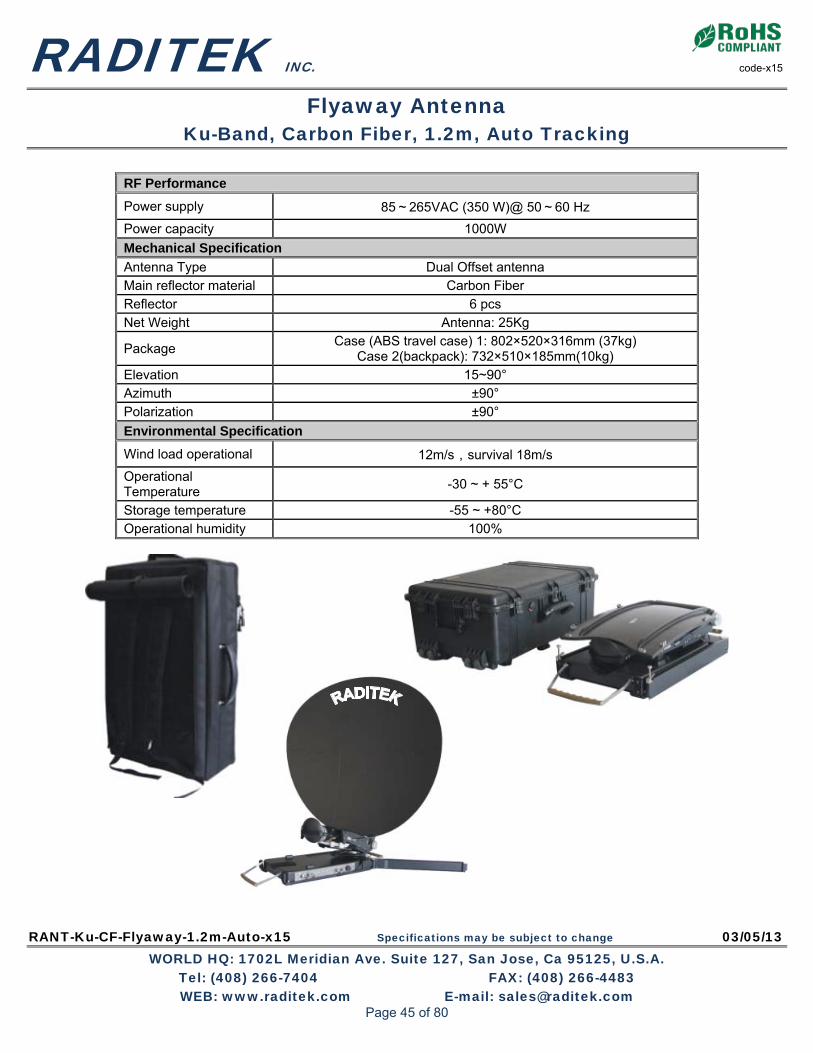
RADITEK INC. code-x15
Flyaway Antenna Ku-Band, Carbon Fiber, 1.2m, Auto Tracking
RANT-Ku-CF-Flyaway-1.2m-Auto-x15 Specifications may be subject to change 03/05/13 WORLD HQ: 1702L Meridian Ave. Suite 127, San Jose, Ca 95125, U.S.A.
Tel: (408) 266-7404 FAX: (408) 266-4483 WEB: www.raditek.com E-mail: [email protected]
RF Performance
Power supply 85~265VAC (350 W)@ 50~60 Hz
Power capacity 1000W
Mechanical Specification
Antenna Type Dual Offset antenna Main reflector material Carbon Fiber Reflector 6 pcs Net Weight Antenna: 25Kg
Package Case (ABS travel case) 1: 802×520×316mm (37kg)
Case 2(backpack): 732×510×185mm(10kg) Elevation 15~90° Azimuth ±90° Polarization ±90°
Environmental Specification
Wind load operational 12m/s,survival 18m/s
Operational Temperature
-30 ~ + 55°C
Storage temperature -55 ~ +80°C Operational humidity 100%
Page 45 of 80

RADITEK INC. code-x15
Flyaway Antenna Ku-Band, Carbon Fiber, 1.2m, Auto Tracking
RANT-Ku-CF-Flyaway-1.2m-Auto-x15 Specifications may be subject to change 03/05/13 WORLD HQ: 1702L Meridian Ave. Suite 127, San Jose, Ca 95125, U.S.A.
Tel: (408) 266-7404 FAX: (408) 266-4483 WEB: www.raditek.com E-mail: [email protected]
0.96 x 1.20 Metre Kue-band Antenna - Horizontal Patterns
Antenna Aperture: Diameter: 960mmx1200mm Co-pol (Co-Polarization) Sidelobe Envelope:
29 - 25 log10 − (off axis angle) from 100lamda / D to 8 Deg X-pol (Cross Polarization) Sidelobe Envelope:
19 - 25 log10 − (off axis angle) from 100lamda / D to 8 Deg
Where lamda is wavelength and D is antenna aperture diameter (0.96 or 1.2m)
Page 46 of 80
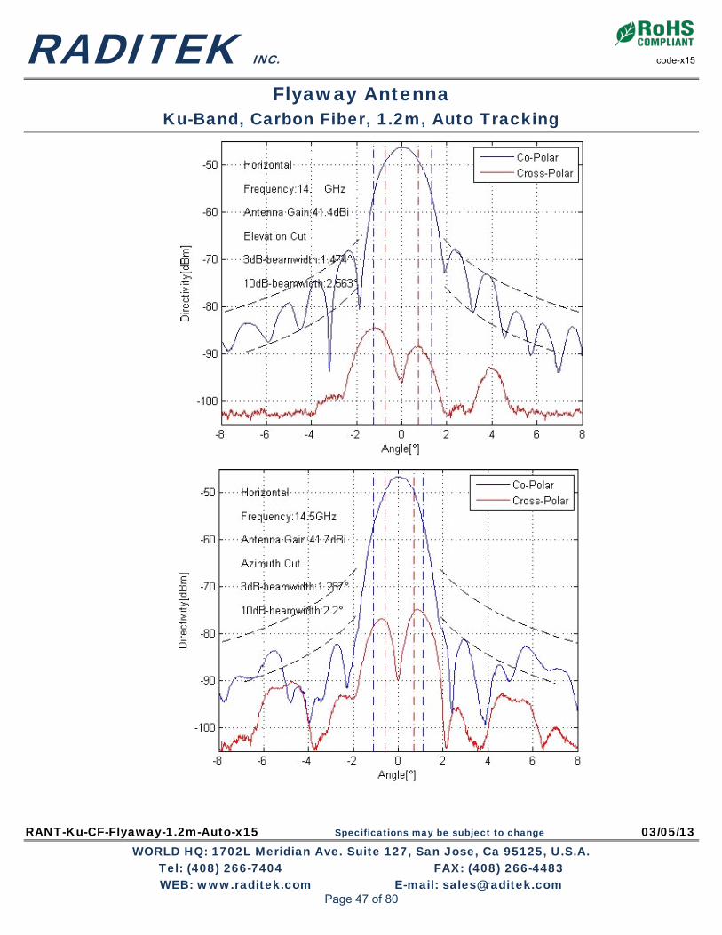
RADITEK INC. code-x15
Flyaway Antenna Ku-Band, Carbon Fiber, 1.2m, Auto Tracking
RANT-Ku-CF-Flyaway-1.2m-Auto-x15 Specifications may be subject to change 03/05/13 WORLD HQ: 1702L Meridian Ave. Suite 127, San Jose, Ca 95125, U.S.A.
Tel: (408) 266-7404 FAX: (408) 266-4483 WEB: www.raditek.com E-mail: [email protected]
Page 47 of 80

RADITEK INC. code-x15
Flyaway Antenna Ku-Band, Carbon Fiber, 1.2m, Auto Tracking
RANT-Ku-CF-Flyaway-1.2m-Auto-x15 Specifications may be subject to change 03/05/13 WORLD HQ: 1702L Meridian Ave. Suite 127, San Jose, Ca 95125, U.S.A.
Tel: (408) 266-7404 FAX: (408) 266-4483 WEB: www.raditek.com E-mail: [email protected]
Page 48 of 80

RADITEK INC. code-x15
Flyaway Antenna Ku-Band, Carbon Fiber, 1.2m, Auto Tracking
RANT-Ku-CF-Flyaway-1.2m-Auto-x15 Specifications may be subject to change 03/05/13 WORLD HQ: 1702L Meridian Ave. Suite 127, San Jose, Ca 95125, U.S.A.
Tel: (408) 266-7404 FAX: (408) 266-4483 WEB: www.raditek.com E-mail: [email protected]
Page 49 of 80

RADITEK INC. code-x15
Flyaway Antenna Ku-Band, Carbon Fiber, 1.2m, Auto Tracking
RANT-Ku-CF-Flyaway-1.2m-Auto-x15 Specifications may be subject to change 03/05/13 WORLD HQ: 1702L Meridian Ave. Suite 127, San Jose, Ca 95125, U.S.A.
Tel: (408) 266-7404 FAX: (408) 266-4483 WEB: www.raditek.com E-mail: [email protected]
Page 50 of 80

RACU-1000-q16 Specifications may be subject to change 08/19/13 WORLD HQ: 1702L Meridian Ave. Suite 127, San Jose, Ca 95125, U.S.A.
Tel: (408) 266-7404 FAX: (408) 266-4483 WEB: www.raditek.com E-mail: [email protected]
The RADITEK, RACU-1000-q16 controller is all you need for any satellite, including inclined satellite, tracking system. The ACU works with any L, C and Ku band antenna from 0.4 to 10m. It offers the best tracking solution for new installations, as well as upgrading, older existing antenna systems. Even if the satellite (up to 5 inclined satellites) has declined into an inclined orbit, for example and it has PC remote control ability, and optically coupled drive outputs, limit inputs that provide isolation between the outdoor unit and the rack mounted RACU-1000-q16. Antenna position sensing is performed by a high resolver system. Up to 38 preset satellites can be stored and fast slewing as well as fine positioning speeds are possible. This controller is designed for future expansion as well, It has extra ports for potentiometer based feed control, RF power measurement circuits, TTL compatible Digital inputs, and form C relay outputs. The ACU continuously monitors: Motion limits, maintenance Drive error, emergency stops and runaway conditions.
Antenna Control Unit RACU-1000-q16 Features Single key antenna positioned Simultaneously displays on front panel LCD:
• Az, El, Pol angles • Received signal strength • Satellite name and longitude
Non Volatile Memory • Stores up to 38 preset position and polarization combination
Continuous Antenna Status Monitoring • Motion limits • Drive error monitoring • Maintenance info. • Emergency stop and runaway conditions
Dual Speed: Fast slewing, fine positioning Inclined Orbit tracking: Step track, memory & search modes PC control: Optional RS-422 interface Opto-isolators: Up to 5KV rated, opto-isolation.
SATCOM L-C-Ku Band ACU
Page 51 of 80

RADITEK INC. code-q16
Antenna Control Unit RACU-1000-q16
RACU-1000-q16 Specifications may be subject to change 08/19/13 WORLD HQ: 1702L Meridian Ave. Suite 127, San Jose, Ca 95125, U.S.A.
Tel: (408) 266-7404 FAX: (408) 266-4483 WEB: www.raditek.com E-mail: [email protected]
The RACU-1000-Q16 has a special intelligent algorithmic search feature that reduces errors associated with traditional “box” search methods.
The RACU search algorithm calculates the satellite trajectory, and stores it for future reference. Even an inclined satellite can be tracked as easily as a normal one. To do this, select AUTO mode, select the satellite from the list there, select the proper polarization, and the RACU-1000-q16 does the rest. This tracking algorithm can be operated in 3 modes:
STEP_TRACK/PROGRAM_TRACK/SEARCH The user jogs the antenna to the satellite, and verifies its’ identity. The system enters… STEP_TRACK MODE: the controller periodically peaks the
receiver’s AGC signal strength, by jogging the antenna. The controller records the time and position in its non volatile memory. The inter-peak interval is determined by antenna beam width, satellite inclination, and a user specified error in dB. STEP_TRACK mode changes to: PROGRAM_TRACK, once the satellite’s motion corresponds to a previously stored normal trajectory. In this mode, the controller smoothly moves the antenna in Azimuth and Elevation, to positions defined in its (pre-stored) tracking tables. Antenna actuator wear can be minimized by a user specified “maximum allowable error” entry, that can result in a fewer antenna movements. The track table accuracy is maintained by peaking the receiver’s AGC periodically. Once the error is out of the operator’s requested range, the all entries in the track table are tagged for update. The user can specify once a day to once a week. If the satellite signal is lost, the SEARCH mode is activated, which uses the intelligent search algorithm to rapidly reacquire satellite lock.
Specifications:
Track mode: Antenna size 0.4 to 10 meters Tracking modes Intelligent, Step and program track Inclined satellites Can track up to 5 AGC inputs 2 x ±15 Volts Input impedance 4 MΩ ANTENNA interface: Control Output Protected, open collector relay drivers Control Output I max=700 mA Control Output Vmax=60 V Positioning Low voltage resolver interface Alarm output 3A @30Vdc or 3A @ 125V (NO and NC) Physical: Size 19 x 3.5 x 9 (rack) inch Weight 19 Lbs Operating temp. 0 to 50 °C Power (AC) 115/230 (48W) VAC 50/60Hz
Page 52 of 80

RBUC-L-Ku-Nf-WR75-ER10M-16-40W-AC-ODU-i13 Specifications may be subject to change 06/27/13 WORLD HQ: 1702L Meridian Ave. Suite 127, San Jose, Ca 95125, U.S.A.
Tel: (408) 266-7404 FAX: (408) 266-4483 WEB: www.raditek.com E-mail: [email protected]
Order Examples: RBUC-L-Kue-WR75-Nf-40W-ER10M AC-ODU-i13 Description: (Block Up Converter, L Band (950-1450MHz) to Kue(13.75-14.5GHz), N-Type Female IF Input Connector,
WR75 Grooved RF Output Connector, 10MHz External Reference, 40 Watts, AC (90-265V) Additional Options: Kue (13.75-14.5GHz) / Ku (14.0-14.5GHz) RF Power: 16, 20, 25 and 40 Watts AC (90-265V), (DC: -48V(32-72V)
*Contact us for the part number per frequency sub-band options.
SATCOM Ku Band MICRA-BUC
Ku-Band Micra-BUC Block-Up-Converter 16, 20, 25, 40Watts, 10MHz Ext. Reference, Outdoor Unit.
Not all BUCs are equal: Raditek’s Ku-Band Block-Up-Converter Family is so compact, its small size and weight facilitate direct antenna feed mounting. It weighs only 5½ lbs, with up to 40W (Rated power), and has a built-in AC (90-265VAC 50-60Hz auto-ranging) power supply, with -48V (DC) optionally available too. These BUCs have the best in class RF performance, including: Internal output isolator and Internet based monitor and control, with both serial and analog interfaces. Ideal for any VSAT application, especially RADITEK’s Internet on the Move (IOTM) for the smallest, lightest weight applications. Also ideal with the Raditek Micra™ single board modem to RADITEK’s highest performance Extreme Modem. KEY FEATURES:
• Up to 40W Linear / 50W Psat (Rated Power) • 6.25"x6.45"x3.5" (extremely small!), 5.5lbs • Ideal for feed horn mounting • Only 250W Power consumption at 40W output • 180W power consumption at 3dB back off. • Excellent RF performance:
Phase noise 6dB better than IESS308/309 Saturated power of 44dBm minimum Spurious below -60dBc Wide dynamic range of Gain Control
• Integrated L-Band to Ku-Band up converter • Overdrive protection on 40W model • High Linearity
• Switchable LO option – Standard (S) and Extended Ku-Band (E) in one unit
• Built In isolator provides full output VSWR Protection
• Output power measurement - True RMS detector installed at factory (optional)
• Configuration via RS-232 serial, packet protocol RS-485 - User friendly HTTP based GUI and SNMP (optional),
• Built in auto-ranging AC power supply • -48VDC isolated power supply (optional) • Field upgradable software • Status LED
(Compare to our competitor, Wavestream, for example:-
Wavestream’s Ku-Band Matchbox BUC 16W/25W/40W 10.3"L x 5.4"W x 4.5"H 10 lbs
Page 53 of 80

RADITEK INC. code-i13
Block Up Converter L to Ku-Band 16, 20, 25, 40Watts, 10MHz Ext Reference, ODU
RBUC-L-Ku-Nf-WR75-ER10M-16-40W-AC-ODU-i13 Specifications may be subject to change 06/27/13 WORLD HQ: 1702L Meridian Ave. Suite 127, San Jose, Ca 95125, U.S.A.
Tel: (408) 266-7404 FAX: (408) 266-4483 WEB: www.raditek.com E-mail: [email protected]
16,20,25W Rated Power Micra-BUCs
Specifications 16W 20W 25W RF Performance RF Frequency Range - (switchable via RS485)
14-14.5GHz (Ku) 13.75-14.5GHz (KuE)
IF Frequency Range 950-1450MHz 950-1700MHz LO Frequency 13.05GHz 12.8GHz Conversion Single Conversion; non-inverting Output Power at Psat 42dBm minimum -16W 43dBm minimum-20W 44dBm minimum -25W Saturated Power 43dBm typical. 44dBm typical. 45dBm typical. Conversion Gain 72dB min, 75dB typical
Gain Flatness ±1dB typical ±1.5dB max over full band;
±0.5dB maximum over any 40MHz Gain Stability ±1.5dB over full temperature range Gain Control 20dB minimum dynamic range External Reference Frequency 10MHz multiplexed with IF In
External Reference Required Phase Noise
-130dBc/Hz @ 100Hz -140dBc/Hz @ 1kHz -150dBc/Hz @ 10kHz
-155dBc/Hz @ 100 kHz
Up-Converter Phase Noise
-70dBc/Hz @ 100Hz; -80dBc/Hz @ 1kHz; -90dBc/Hz @ 10kHz -95dBc/Hz @ 100kHz -115dBc/Hz @ 1MHz
Linearity: 2 tone IMD -25dBc at 3dB total power back off from Psat.
-30dBc for QPSK at 1.5xsymbol rate at 2dB back off from Psat. Output Spurious: Non-signal related Signal related
-60dBc -55dBc
Power AC Voltage Range 90-265VAC 50-60Hz auto-ranging 48V DC Voltage Range (optional) (-48V) 32-72VDC Isolated (with reverse voltage protection) Power Consumption 180W(16W RF) 220W (20W RF) 250W (25W RF) Mechanical Size 6.25"x6.45"x3.9" Weight 5.5lbs Cooling Forced Air Operating temperature -40C to +60C Relative Humidity Up to 100% condensing Interfaces IF Input Connector N-type female RF Output Connector WR75 grooved AC Power In Connector MS3112E10-8P RS485-RS232-Ethernet-SNMP MS3112E14-19S
Page 54 of 80

RADITEK INC. code-i13
Block Up Converter L to Ku-Band 16, 20, 25, 40Watts, 10MHz Ext Reference, ODU
RBUC-L-Ku-Nf-WR75-ER10M-16-40W-AC-ODU-i13 Specifications may be subject to change 06/27/13 WORLD HQ: 1702L Meridian Ave. Suite 127, San Jose, Ca 95125, U.S.A.
Tel: (408) 266-7404 FAX: (408) 266-4483 WEB: www.raditek.com E-mail: [email protected]
40W Rated Power Micra-BUC.
Parameter 40W RF Performance RF Frequency Range 14-14.5GHz (Ku) 13.75-14.5GHz (KuE) IF Frequency Range 950-1450MHz 950-1700MHz LO Frequency 13.05GHz 12.8GHz Conversion Single Conversion; non-inverting Rated Power (Psat) 46dBm Conversion Gain 72dB min, 75dB typ
Gain Flatness ±1dB typ ±1.5dB max over full band;
±0.5dB max over any 40MHz Gain Stability ±1.5dB over full temperature range Gain Control 20dB min dynamic range External Reference Frequency 10MHz multiplexed with IF In
External Reference Required Phase Noise
-130dBc/Hz @ 100Hz -140dBc/Hz @ 1kHz
-150dBc/Hz @ 10kHz -155dBc/Hz @ 100 kHz
Up-Converter Phase Noise
70dBc/Hz @ 100Hz; -80dBc/Hz @ 1kHz; -90dBc/Hz @ 10kHz -95dBc/Hz @ 100kHz -115dBc/Hz @ 1MHz
Linearity: 2 tone IMD -24dBc at 43 dBm (20W) -30dBc at 40dBm (10W)
-30dBc for QPSK at 1.5xsymbol rate at 44dBm Output Spurious: Non-signal related Signal related
-60dBc -55dBc
Power AC Voltage Range 90-265VAC 50-60Hz auto-ranging 48V DC Voltage Range (optional) -48 (36-75VDC)
Power Consumption 250W at rated power (P1dB) 180W at 3dB back off/linear
Mechanical Size 6.25"x6.45"x3.5" Weight 5.5lbs Cooling Forced Air Operating temperature -40C to +60C Relative Humidity Up to 100% condensing Interfaces IF Input Connector N-type female RF Output Connector WR75 grooved AC Power In Connector MS3112E10-8P RS485-RS232-Ethernet-SNMP MS3112E14-19S
Page 55 of 80

RBUC-L-C-Nf-CPR137-ER10M-20-80W-AC-ODU-i13 Specifications may be subject to change 07/10/13 WORLD HQ: 1702L Meridian Ave. Suite 127, San Jose, Ca 95125, U.S.A.
Tel: (408) 266-7404 FAX: (408) 266-4483 WEB: www.raditek.com E-mail: [email protected]
Order Examples: RBUC-L-Cs-Nf-CPR137-ER10M-20W-AC-ODU-i13 Description: (Block Up Converter, L Band(950-1525MHz) to C(5.85-6.425GHz), N-Type Female IF Input Connector,
CPR137 Grooved RF Output Connector, 10MHz External Reference, 20 Watts, AC A90-265V), Outdoor Unit Additional Options: Opt: Cs Standard, Ce Extended, Ci Insat, Cp Palapa 40, 80Watts -48V DC (32-72V) Isolated *Contact us for the part number per frequency sub-band options.
SATCOM L-C Band BUC
L- to C-Band Block-Up-Converter 20, 40, 80Watts, 10MHz External Reference, ODU
Not all BUCs are equal: Raditek C-Band Block-Up-Converter Family is so compact, its small size and weight facilitate direct feed horn/antenna mounting. It weighs only 5½ lbs, with up to 80W Psat, and has a built-in AC (90-265VAC 50-60Hz auto-ranging) power supply, with -48V (DC) optionally available too. These BUCs have the best in class RF performance, including: Internal output isolator and Internet based monitor and control, with both serial and analog interfaces.
Key Features
• Up to 80W Psat in this super-compact and light weight package 6.25"x6.45"x3.9" only!
• Suitable for feed horn mounting • Best RF performance:
o Phase noise 10dB better than IESS308/309 o Psat of 49dBm Spurious below -60dBc o Wide dynamic range of Gain Control
• Integrated L-Band to C-Band conversion Available also in Standard, Extended, Palapa and Insat frequency options.
• Built In Output Isolator • Output power measurement has RMS detector • Configuration via RS-232 serial console, packet
protocol RS-485 - User friendly HTTP based GUI and SNMP optional
• Built in auto-ranging AC power supply • -48VDC isolated power supply (optional) • Field upgradable software • Status LED • Overdrive Protection on 80W model
Page 56 of 80

RADITEK INC. code -i13
Block Up Converter L to C-Band 20, 40, 80Watts, 10MHz External Reference, ODU
RBUC-L-C-Nf-CPR137-ER10M-20-80W-AC-ODU-i13 Specifications may be subject to change 07/10/13 WORLD HQ: 1702L Meridian Ave. Suite 127, San Jose, Ca 95125, U.S.A.
Tel: (408) 266-7404 FAX: (408) 266-4483 WEB: www.raditek.com E-mail: [email protected]
20,40W PSAT
Parameter 20W 40W RF Performance RF Frequency Range-Available in/switched:
5.85-6.425GHz (other frequency options available)
IF Frequency Range 950-1525MHz LO Frequency 4.9 GHz (other options available) Conversion Single Conversion; non-inverting Output Power at 1dB compression point 43dBm min 46dBm min Saturated Power 44dBm typ 47dBm typ Conversion Gain 72dB min, 75dB typ
Gain Flatness +/-1dB typ +/-1.5dB max over full band;
+/-0.5dB max over any 40MHz Gain Stability +/-1.5dB over full temperature range Gain Control 20dB min dynamic range External Reference Frequency 10MHz multiplexed with IF In External Reference Required Phase Noise
-130dBc/Hz @ 100Hz -140dBc/Hz @ 1kHz -150dBc/Hz @ 10kHz -155dBc/Hz @ 100 kHz
Up-Converter Phase Noise -70dBc/Hz @ 100Hz; -80dBc/Hz @ 1kHz; -90dBc/Hz @ 10kHz
-95dBc/Hz @ 100kHz -115dBc/Hz @ 1MHz Linearity: 2 tone IMD Spectral Re-growth
-26dBc at 3dB total power back off from P1dB -30dBc for QPSK at 1.5xsymbol rate at 2dB back off from P1dB
Output Spurious: Non-signal related Signal related
-60dBc -55dBc
Power AC Voltage Range 90-265VAC 50-60Hz auto-ranging 48V DC Voltage Range (optional) 32-72VDC Isolated Power Consumption 180W 220W Mechanical Size 6.25"x6.45"x3.9" Weight 5.5lbs Cooling Forced Air Operating temperature -40C to +60C Relative Humidity Up to 100% condensing Interfaces IF Input Connector N-type female RF Output Connector CPR137 Grooved AC Power In MS3112E10-8P RS485-RS232-Ethernet-SNMP MS3112E14-19S
Page 57 of 80

RADITEK INC. code -i13
Block Up Converter L to C-Band 20, 40, 80Watts, 10MHz External Reference, ODU
RBUC-L-C-Nf-CPR137-ER10M-20-80W-AC-ODU-i13 Specifications may be subject to change 07/10/13 WORLD HQ: 1702L Meridian Ave. Suite 127, San Jose, Ca 95125, U.S.A.
Tel: (408) 266-7404 FAX: (408) 266-4483 WEB: www.raditek.com E-mail: [email protected]
80W PSAT
Parameter 80W RF Performance RF Frequency Range-Available in/switched:
5.85-6.425GHz (other frequency options available)
IF Frequency Range 950-1525MHz LO Frequency 4.9 GHz Conversion Single Conversion; non-inverting Rated Power 49dBm Conversion Gain 75dB min, 77dB typ
Gain Flatness +/-1dB typ +/-1.5dB max over full band;
+/-0.5dB max over any 40MHz Gain Stability +/-1.5dB over full temperature range Gain Control 20dB min dynamic range External Reference Frequency 10MHz multiplexed with IF In External Reference Required Phase Noise
-130dBc/Hz @ 100Hz -140dBc/Hz @ 1kHz -150dBc/Hz @ 10kHz -155dBc/Hz @ 100 kHz
Up-Converter Phase Noise -70dBc/Hz @ 100Hz; -80dBc/Hz @ 1kHz; -90dBc/Hz @ 10kHz
-95dBc/Hz @ 100kHz -115dBc/Hz @ 1MHz
Linearity: 2 tone IMD Spectral Re-growth
-25dBc at 3dB total power back off from rated power -30dBc at 6dB total power back off from rated power
-30dBc for QPSK at 1.5xsymbol rate at 2dB back off from rated power Output Spurious: Non-signal related Signal related
-60dBc -55dBc
Power AC Voltage Range 90-265VAC 50-60Hz auto-ranging 48V DC Voltage Range (optional) 32-72VDC Isolated
Power Consumption 350W at rated power
270W at 3dB back off from rated power Mechanical Size 6.25"x6.45"x3.9" Weight 5.5lbs Cooling Forced Air Operating temperature -40C to +60C Relative Humidity Up to 100% condensing Interfaces IF Input Connector N-type female RF Output Connector CPR137 grooved AC Power In MS3112E10-8P RS485-RS232-Ethernet-SNMP MS3112E14-19S
Page 58 of 80

RADITEK INC. code -i13
Block Up Converter L to C-Band 20, 40, 80Watts, 10MHz External Reference, ODU
RBUC-L-C-Nf-CPR137-ER10M-20-80W-AC-ODU-i13 Specifications may be subject to change 07/10/13 WORLD HQ: 1702L Meridian Ave. Suite 127, San Jose, Ca 95125, U.S.A.
Tel: (408) 266-7404 FAX: (408) 266-4483 WEB: www.raditek.com E-mail: [email protected]
Note 1. System IF input can be routed to an input splitter or coaxial switch (as a part of ganged WG switch) depending on system configuration. Note 2. Stand by unit canbe running in hold over mode using internal low stability reference clock signal to provide “hot standby” operation in case of external reference being switched to the active unit only. Note 3. Indoor RU Remoter control Panel can be added to the system as an option for customer convenience.
Page 59 of 80
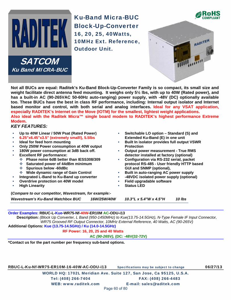
RBUC-L-Ku-Nf-WR75-ER10M-16-40W-AC-ODU-i13 Specifications may be subject to change 06/27/13 WORLD HQ: 1702L Meridian Ave. Suite 127, San Jose, Ca 95125, U.S.A.
Tel: (408) 266-7404 FAX: (408) 266-4483 WEB: www.raditek.com E-mail: [email protected]
Order Examples: RBUC-L-Kue-WR75-Nf-40W-ER10M AC-ODU-i13 Description: (Block Up Converter, L Band (950-1450MHz) to Kue(13.75-14.5GHz), N-Type Female IF Input Connector,
WR75 Grooved RF Output Connector, 10MHz External Reference, 40 Watts, AC (90-265V) Additional Options: Kue (13.75-14.5GHz) / Ku (14.0-14.5GHz) RF Power: 16, 20, 25 and 40 Watts AC (90-265V), (DC: -48V(32-72V)
*Contact us for the part number per frequency sub-band options.
SATCOM Ku Band MICRA-BUC
Ku-Band Micra-BUC Block-Up-Converter 16, 20, 25, 40Watts, 10MHz Ext. Reference, Outdoor Unit.
Not all BUCs are equal: Raditek’s Ku-Band Block-Up-Converter Family is so compact, its small size and weight facilitate direct antenna feed mounting. It weighs only 5½ lbs, with up to 40W (Rated power), and has a built-in AC (90-265VAC 50-60Hz auto-ranging) power supply, with -48V (DC) optionally available too. These BUCs have the best in class RF performance, including: Internal output isolator and Internet based monitor and control, with both serial and analog interfaces. Ideal for any VSAT application, especially RADITEK’s Internet on the Move (IOTM) for the smallest, lightest weight applications. Also ideal with the Raditek Micra™ single board modem to RADITEK’s highest performance Extreme Modem. KEY FEATURES:
• Up to 40W Linear / 50W Psat (Rated Power) • 6.25"x6.45"x3.5" (extremely small!), 5.5lbs • Ideal for feed horn mounting • Only 250W Power consumption at 40W output • 180W power consumption at 3dB back off. • Excellent RF performance:
Phase noise 6dB better than IESS308/309 Saturated power of 44dBm minimum Spurious below -60dBc Wide dynamic range of Gain Control
• Integrated L-Band to Ku-Band up converter • Overdrive protection on 40W model • High Linearity
• Switchable LO option – Standard (S) and Extended Ku-Band (E) in one unit
• Built In isolator provides full output VSWR Protection
• Output power measurement - True RMS detector installed at factory (optional)
• Configuration via RS-232 serial, packet protocol RS-485 - User friendly HTTP based GUI and SNMP (optional),
• Built in auto-ranging AC power supply • -48VDC isolated power supply (optional) • Field upgradable software • Status LED
(Compare to our competitor, Wavestream, for example:-
Wavestream’s Ku-Band Matchbox BUC 16W/25W/40W 10.3"L x 5.4"W x 4.5"H 10 lbs
Page 60 of 80
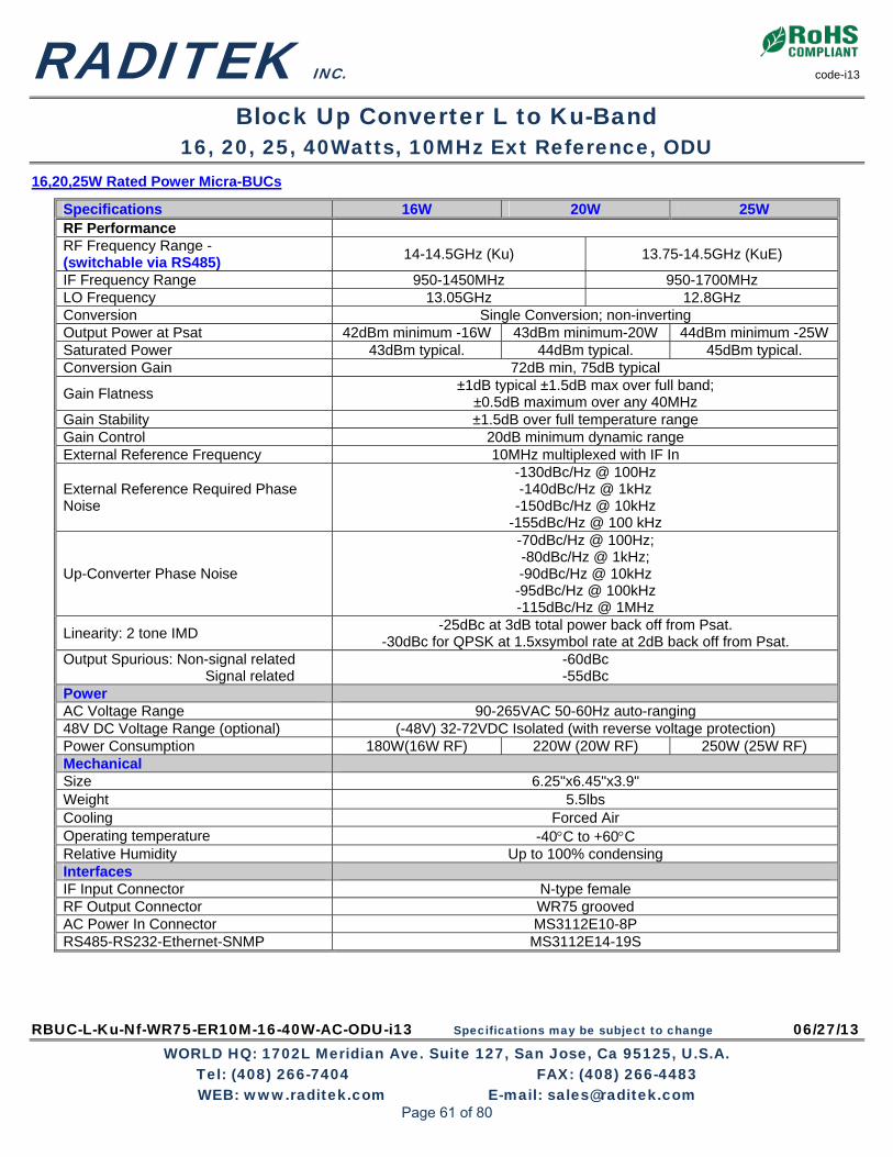
RADITEK INC. code-i13
Block Up Converter L to Ku-Band 16, 20, 25, 40Watts, 10MHz Ext Reference, ODU
RBUC-L-Ku-Nf-WR75-ER10M-16-40W-AC-ODU-i13 Specifications may be subject to change 06/27/13 WORLD HQ: 1702L Meridian Ave. Suite 127, San Jose, Ca 95125, U.S.A.
Tel: (408) 266-7404 FAX: (408) 266-4483 WEB: www.raditek.com E-mail: [email protected]
16,20,25W Rated Power Micra-BUCs
Specifications 16W 20W 25W RF Performance RF Frequency Range - (switchable via RS485)
14-14.5GHz (Ku) 13.75-14.5GHz (KuE)
IF Frequency Range 950-1450MHz 950-1700MHz LO Frequency 13.05GHz 12.8GHz Conversion Single Conversion; non-inverting Output Power at Psat 42dBm minimum -16W 43dBm minimum-20W 44dBm minimum -25W Saturated Power 43dBm typical. 44dBm typical. 45dBm typical. Conversion Gain 72dB min, 75dB typical
Gain Flatness ±1dB typical ±1.5dB max over full band;
±0.5dB maximum over any 40MHz Gain Stability ±1.5dB over full temperature range Gain Control 20dB minimum dynamic range External Reference Frequency 10MHz multiplexed with IF In
External Reference Required Phase Noise
-130dBc/Hz @ 100Hz -140dBc/Hz @ 1kHz -150dBc/Hz @ 10kHz
-155dBc/Hz @ 100 kHz
Up-Converter Phase Noise
-70dBc/Hz @ 100Hz; -80dBc/Hz @ 1kHz; -90dBc/Hz @ 10kHz -95dBc/Hz @ 100kHz -115dBc/Hz @ 1MHz
Linearity: 2 tone IMD -25dBc at 3dB total power back off from Psat.
-30dBc for QPSK at 1.5xsymbol rate at 2dB back off from Psat. Output Spurious: Non-signal related Signal related
-60dBc -55dBc
Power AC Voltage Range 90-265VAC 50-60Hz auto-ranging 48V DC Voltage Range (optional) (-48V) 32-72VDC Isolated (with reverse voltage protection) Power Consumption 180W(16W RF) 220W (20W RF) 250W (25W RF) Mechanical Size 6.25"x6.45"x3.9" Weight 5.5lbs Cooling Forced Air Operating temperature -40C to +60C Relative Humidity Up to 100% condensing Interfaces IF Input Connector N-type female RF Output Connector WR75 grooved AC Power In Connector MS3112E10-8P RS485-RS232-Ethernet-SNMP MS3112E14-19S
Page 61 of 80

RADITEK INC. code-i13
Block Up Converter L to Ku-Band 16, 20, 25, 40Watts, 10MHz Ext Reference, ODU
RBUC-L-Ku-Nf-WR75-ER10M-16-40W-AC-ODU-i13 Specifications may be subject to change 06/27/13 WORLD HQ: 1702L Meridian Ave. Suite 127, San Jose, Ca 95125, U.S.A.
Tel: (408) 266-7404 FAX: (408) 266-4483 WEB: www.raditek.com E-mail: [email protected]
40W Rated Power Micra-BUC.
Parameter 40W RF Performance RF Frequency Range 14-14.5GHz (Ku) 13.75-14.5GHz (KuE) IF Frequency Range 950-1450MHz 950-1700MHz LO Frequency 13.05GHz 12.8GHz Conversion Single Conversion; non-inverting Rated Power (Psat) 46dBm Conversion Gain 72dB min, 75dB typ
Gain Flatness ±1dB typ ±1.5dB max over full band;
±0.5dB max over any 40MHz Gain Stability ±1.5dB over full temperature range Gain Control 20dB min dynamic range External Reference Frequency 10MHz multiplexed with IF In
External Reference Required Phase Noise
-130dBc/Hz @ 100Hz -140dBc/Hz @ 1kHz
-150dBc/Hz @ 10kHz -155dBc/Hz @ 100 kHz
Up-Converter Phase Noise
70dBc/Hz @ 100Hz; -80dBc/Hz @ 1kHz; -90dBc/Hz @ 10kHz -95dBc/Hz @ 100kHz -115dBc/Hz @ 1MHz
Linearity: 2 tone IMD -24dBc at 43 dBm (20W) -30dBc at 40dBm (10W)
-30dBc for QPSK at 1.5xsymbol rate at 44dBm Output Spurious: Non-signal related Signal related
-60dBc -55dBc
Power AC Voltage Range 90-265VAC 50-60Hz auto-ranging 48V DC Voltage Range (optional) -48 (36-75VDC)
Power Consumption 250W at rated power (P1dB) 180W at 3dB back off/linear
Mechanical Size 6.25"x6.45"x3.5" Weight 5.5lbs Cooling Forced Air Operating temperature -40C to +60C Relative Humidity Up to 100% condensing Interfaces IF Input Connector N-type female RF Output Connector WR75 grooved AC Power In Connector MS3112E10-8P RS485-RS232-Ethernet-SNMP MS3112E14-19S
Page 62 of 80

RBUC-L-Ku-Nf-WR75-ER10M-150-200W-AC-ODU-i13 Specifications may be subject to change 03/05/13 WORLD HQ: 1702L Meridian Ave. Suite 127, San Jose, Ca 95125, U.S.A.
Tel: (408) 266-7404 FAX: (408) 266-4483 WEB: www.raditek.com E-mail: [email protected]
Order Examples: RBUC-L-Kue-Nf-WR75-ER10M-200W-AC-ODU -i13 Description: (Block Up Converter, L Band (950-1700MHz) to Ku (13.75-14.5MHz) N-Type Female IF Input Connector,
WR75 Grooved RF Output Waveguide, 10MHz External Reference, (200 Watts P1db, AC (190-260V), ODU) Additional Options: Ku (14.0-14.5GHz) switchable (150W option)
SATCOM L-Ku Band BUC
L- to Ku-Band Block-Up-Converter 150, 200Watts, 10MHz Ext Reference, ODU
Not all BUCs are equal: Raditek Ku-Band Block-Up-Converter Family is so compact, its small size and weight facilitate simplified antenna mounting. It weighs only 92 lbs, in either 150W (P1dB)/ or 200W (P1dB)/250W (Psat), and has a built-in AC (190-265VAC 50-60Hz auto-ranging) power supply. These BUCs have the best in class RF performance, including: Internal output isolator and Internet based monitor and control, with both serial and analog interfaces.
Key Features:
• Patent pending Combiner, allowing extremely high power density -to 250W Psat
• 16"x13"x10.7" Extremely small housing! • Superior RF performance:
o Phase noise 10dB better than IESS308/309 o P1dB of 53dBm (200W) o Spurious below -60dBc o Wide dynamic range of Gain Control
• RF Overdrive Protection • Available in both standard (Ku) and Extended
Ku-Band (Kue) • Switchable LO option - standard (Ku) and
Extended Ku-Band (Kue) in one unit
• Input and Output True RMS Power Detection • Output power measurement - True RMS detector • Configuration via RS-232 serial, packet protocol
RS-485 – IP based HTTP based GUI and SNMP optional
• Automated Level Control (ALC) Option • Redundant ready - No external controller
required for 1:N redundant configuration • Field replaceable plug-In Power Supply • Field upgradable software • Status LED
Page 63 of 80

RADITEK INC. code-i13
Block Up Converter L to Ku-Band 150-200Watts, 10MHz Ext Reference, ODU
RBUC-L-Ku-Nf-WR75-ER10M-150-200W-AC-ODU-i13 Specifications may be subject to change 03/05/13 WORLD HQ: 1702L Meridian Ave. Suite 127, San Jose, Ca 95125, U.S.A.
Tel: (408) 266-7404 FAX: (408) 266-4483 WEB: www.raditek.com E-mail: [email protected]
Specifications RF Performance RF Frequency Range- 14-14.5GHz (Ku) 13.75-14.5GHz (Kue) IF Frequency Range 950-1450MHz 950-1700MHz LO Frequency 13.05GHz 12.8GHz Conversion Single Conversion; non-inverting 150W 200W Output Power at 1dB compression point 52dBm min (150W) 53dBm min (200W) Saturated Power 53dBm typ 54dBm typ Conversion Gain 75dB min, 77dB typ
Gain Flatness ±1dB typ +/-1.5dB max over full band;
±0.5dB max over any 40MHz Gain Stability ±1.5dB over full temperature range Gain Control 20dB min dynamic range External Reference Frequency 10MHz multiplexed with IF In
External Reference Required Phase Noise
-130dBc/Hz @ 100Hz -140dBc/Hz @ 1kHz -150dBc/Hz @ 10kHz
-155dBc/Hz @ 100 kHz
Up-Converter Phase Noise
-70dBc/Hz @ 100Hz; -80dBc/Hz @ 1kHz; -90dBc/Hz @ 10kHz -95dBc/Hz @ 100kHz -115dBc/Hz @ 1MHz
Linearity: 2 tone IMD -25dBc at 3dB total power back off from P1dB
-30dBc for QPSK at 1.5xsymbol rate at 2dB back off from P1dB Output Spurious: Non-signal related Signal related
-60dBc -55dBc
Power AC Voltage Range 190-265VAC 50-60Hz auto-ranging PFC Power Consumption 1600W (for 150W RF) 1800W (for 200W RF) Mechanical Size 16"x13"x10.7" Weight 92lbs Cooling Forced Air Operating temperature -40C to +55C Relative Humidity Up to 100% condensing Interfaces IF Input Connector N-type female RF Output waveguide WR75 grooved AC Power In Connector TE 788188 M&C Interfaces Redundant Interfaces
Serial In MS3112E12-10S; Alarm In MS3112E12-14S; Ethernet RJ45 Redundancy Protection Int MS31112E14-19S; Switch In MS3112E14-15S
Page 64 of 80

RUDC-70M-L-ER10M-AC-IDU-i13 Specifications may be subject to change 03/05/13 WORLD HQ: 1702L Meridian Ave. Suite 127, San Jose, Ca 95125, U.S.A.
Tel: (408) 266-7404 FAX: (408) 266-4483 WEB: www.raditek.com E-mail: [email protected]
Our Frequency Converters offer a new best in class for the Industry. Not only for ease of operation, but lowest cost too. They embody embedded redundancy options and extensive monitor and control via: front panel, serial ports (EIA232/EIA485) and Ethernet. RUC-Up Converter; RDC-Down Converter There may be up to 4 converter modules in a single 1RU shelf, and they can be configured for various applications and bands. The reference with autosensing can lock to an external 5/10 MHz reference or utilize the built-in high stab, reference oscillator. Hot-swappable shelf redundancy option and extensive monitor and control via front panel, serial ports EIA232/EIA485 and Ethernet.
Order Examples: RUC-70M-L-ER10M-AC-IDU i13 UpConverter RDC-L-70M-ER-AC-IDU.i13 Down Converter Description : (Up Converter, 70MHz (IF) to L-Band, REF (Down Converter, to L-Band to 70MHz (IF), REF eg 10M ER, 10 MHz Voltage-AC or DC eg 10M ER, 10 MHz Voltage-AC or DC
Key Features:
Superior RF performance:
Phase noise >8dB better than IESS308/309
In-band Spurious < -60dBc
Superior Gain flatness
Very wide IF frequency band: 950 to 2150 MHz
5 or 10MHz external reference with Autosense.
-48VDC power supply optional
Synthesizer frequency step of 1kHz with optional 1 Hz step size
Full featured M&C Interface via serial EIA485, EIA232 and Ethernet:
25dB Gain Control (30dB optional) dynamic range
Input and output power detectors
Automated level control (ALC) mode available
Hitless redundancy switching
1:1 and 1:N Redundant ready
Redundancy is supported with hot swappable converters and power supply
10MHz and DC injected into L-Band
Power Supply: Mechanical IF/RF Connectors:
Input Voltage AC option
90 to 265VAC 50/60Hz PFC
Width 19" Rack L band mon.
(option) BNC (other options available)
DC option -48VDC Height 1RU IF mon. (option)
BNC (other options available)
Environmental: Depth 20” RF N-type
Operating temp, 0 to 60 °C Color Light tan 10MHz Ref. BNC (other options available)
Storage Temp. -40 to +85 °C Cooling Forced air IF BNC (other options available)
Humidity 0 to 95% (non-condensing)
SATCOM UP/DownConverter
Up and Down Converter family Rack Mount: 70M to L Band, L band to 70MHz
Page 65 of 80

RADITEK INC. code-i13
Up and Down Converter Family 70M to L Band, L band to 70MHz (Rack mount)
RUDC-70M-L-ER10M-AC-IDU-i13 Specifications may be subject to change 03/05/13 WORLD HQ: 1702L Meridian Ave. Suite 127, San Jose, Ca 95125, U.S.A.
Tel: (408) 266-7404 FAX: (408) 266-4483 WEB: www.raditek.com E-mail: [email protected]
70/140MHz TO L-Band Up/Down Converter
Specification: Upconverter Down converter Monitor & Control Features
Frequency Range: IF Input IF Output Interfaces: 70MHz IF 70MHz +/-18MHz Serial - EIA485 DB9 Connector (rear panel) 140MHz IF 140MHz +/-36MHz Serial - EIA232 RJ45 or DB9 (rear panel) O/P Power @ P1dB N/A 5dBm min 10/100 base-T Ethernet RJ45 (rear panel) Alarm and Control DB9 Connector rear panel Max. Input Level 10dBm N/A Redund. prot. interface DB15 Connector rear panel Impedance 50 Ω / 75 Ω optional Controls: Return Loss -18dB max Gain Control Serial, Ethernet, Front panel RF Characteristics RF Output RF Input Uplink Freq Control Serial, Ethernet, Front panel Frequency Range: 950-2150MHz 950-2150MHz Downlink Freq Control Serial, Ethernet, Front panel
Frequency Step 1kHz/1Hz Mute Control Serial, Ethernet, Front panel, Red LED.
Output Power @P1dB
15dBm min N/A Local/Remote toggle Serial (Ethernet) / Front panel toggle
2 tone IMD at 0dBm Pout
-40dBc max N/A Clear Alarm Serial, Ethernet, Front panel
Gain Control 25dB range 0.1dB step Indicators: 10MHz Reference Out
Multiplexed at RF out port optional Uplink Frequency Serial, Ethernet, Front panel
DC Mux’d on L-Band 24VDC 2A 24VDC 0.5A Downlink Frequency Serial, Ethernet, Front panel Impedance 50 Ω / 75 Ω optional Gain Status Serial, Ethernet, Front panel Return Loss 1.5 Max Input Level N/A Operational up to 0dBm No Damage up to 10dBm IF Power Detect Serial, Ethernet, Front panel Transfer Characteristics: RF Power Detect Serial, Ethernet, Front panel Conversion Gain 30 dB (Optional 35 dB) Temperature Serial, Ethernet, Front panel
Gain Adjustment 25dB with 0.1dB step (Optional 30 dB) Summary Alarm Status Serial, Ethernet, Front panel, Red Int
Gain Flatness with 70MHz IF:
Over full L- band: ±1.0 max. Over 36MHz: ±0.5 max.
Mute Status Serial, Ethernet, Front panel, Red Int
Reference Frequency Stability LO Phase Noise Aging (0.01PPB ) +/-100ppb per year @ 100Hz -70dBc Reference Phase Noise, 10MHz, (5MHz option) @ 1kHz -90dBc @ 10Hz -125dBc/Hz @ 10kHz -95dBc @ 100Hz -140dBc/Hz @ 100kHz -95dBc @ 1kHz -150dBc/Hz @ 1MHz -115dBc @ 10kHz -155dBc/Hz
In Band Spurious <-60dBc Power Level at L-Band Port
+5dBm+/-2dB Optional
Reference 10MHz (5MHz Optional) Int./Ext. Autosense Int. clock locks on ext. ref.
Page 66 of 80
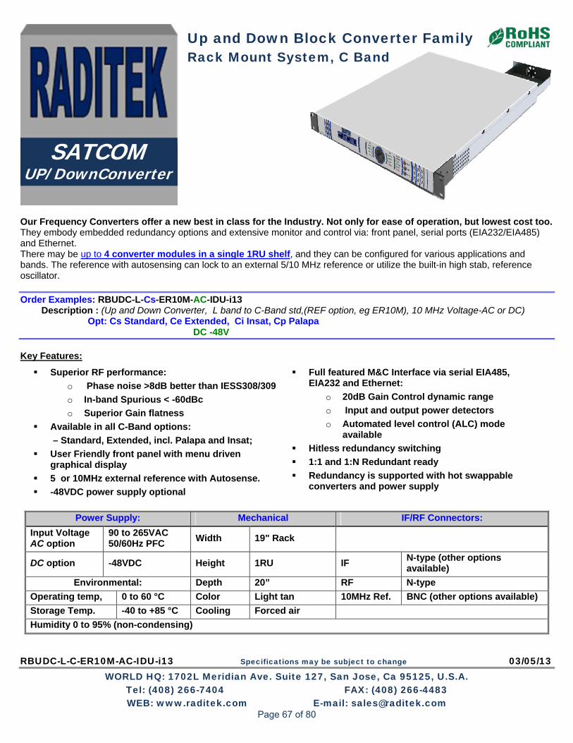
RBUDC-L-C-ER10M-AC-IDU-i13 Specifications may be subject to change 03/05/13 WORLD HQ: 1702L Meridian Ave. Suite 127, San Jose, Ca 95125, U.S.A.
Tel: (408) 266-7404 FAX: (408) 266-4483 WEB: www.raditek.com E-mail: [email protected]
Our Frequency Converters offer a new best in class for the Industry. Not only for ease of operation, but lowest cost too. They embody embedded redundancy options and extensive monitor and control via: front panel, serial ports (EIA232/EIA485) and Ethernet. There may be up to 4 converter modules in a single 1RU shelf, and they can be configured for various applications and bands. The reference with autosensing can lock to an external 5/10 MHz reference or utilize the built-in high stab, reference oscillator. Order Examples: RBUDC-L-Cs-ER10M-AC-IDU-i13
Description : (Up and Down Converter, L band to C-Band std,(REF option, eg ER10M), 10 MHz Voltage-AC or DC) Opt: Cs Standard, Ce Extended, Ci Insat, Cp Palapa
DC -48V Key Features:
Superior RF performance:
o Phase noise >8dB better than IESS308/309
o In-band Spurious < -60dBc
o Superior Gain flatness
Available in all C-Band options:
– Standard, Extended, incl. Palapa and Insat;
User Friendly front panel with menu driven graphical display
5 or 10MHz external reference with Autosense.
-48VDC power supply optional
Full featured M&C Interface via serial EIA485, EIA232 and Ethernet:
o 20dB Gain Control dynamic range
o Input and output power detectors
o Automated level control (ALC) mode available
Hitless redundancy switching
1:1 and 1:N Redundant ready
Redundancy is supported with hot swappable converters and power supply
Power Supply: Mechanical IF/RF Connectors:
Input Voltage AC option
90 to 265VAC 50/60Hz PFC
Width 19" Rack
DC option -48VDC Height 1RU IF N-type (other options available)
Environmental: Depth 20” RF N-type
Operating temp, 0 to 60 °C Color Light tan 10MHz Ref. BNC (other options available)
Storage Temp. -40 to +85 °C Cooling Forced air
Humidity 0 to 95% (non-condensing)
SATCOM UP/DownConverter
Up and Down Block Converter Family Rack Mount System, C Band
Page 67 of 80

RADITEK INC. code-i13
Up and Down Converter Family L-Band to C Band Block Up Converter (IDU-Rack mount)
RBUDC-L-C-ER10M-AC-IDU-i13 Specifications may be subject to change 03/05/13 WORLD HQ: 1702L Meridian Ave. Suite 127, San Jose, Ca 95125, U.S.A.
Tel: (408) 266-7404 FAX: (408) 266-4483 WEB: www.raditek.com E-mail: [email protected]
Specifications: RF Performance Cs Standard C Ce Extended C Cp Palapa Ci Insat RF Frequency Range-GHz Available in/switched:
5.85-6.425 5.85-6.725 6.425-6.725 6.725-7.025
IF Frequency Range MHz 950-1525 950-1825 950-1250 1250-1550 LO Frequency GHz 4.9 5.475 Conversion Single Conversion; non-inverting Output Power at P1dB 10 dBm min Conversion Gain 35 dB typical 30dB min. Gain Flatness ±1dB typ, ±1.5dB max over full band; ±0.5dB max over any 40MHz Gain Stability ±1.5dB over full temperature range Gain Control 20dB min dynamic range External Reference Freq. 10MHz
External Reference Phase Noise (typ. required)
-130dBc/Hz @ 100Hz -140dBc/Hz @ 1kHz -150dBc/Hz @ 10kHz -155dBc/Hz @ 100 Hz
Up-Converter Phase Noise (Depends on reference)
-70dBc/Hz @ 100Hz -80dBc/Hz @ 1kHz -90dBc/Hz @ 10kHz
-95dBc/Hz @ 100kHz -115dBc/Hz @ 1MHz
Spurious
Signal related -55dBc For Extended Band Flatness ±1.5dB typical For Extended Band signal, related Spurious -45dBc
Non signal related -60dBc Interfaces: Serial - EIA485 DSUB Connector (Rear panel) Serial - EIA232 USB (Front Panel) Ethernet RJ45 (Rear Panel Redundant protection port DSUB Connector (Rear panel) Controls: Gain Control Serial, Ethernet, Front panel Mute Control Serial, Ethernet, Front panel, Red LED Local/Remote toggle Serial(Ethernet)/Front panel toggle Clear Alarm Serial, Ethernet, Front panel Indicators: Lock Status Serial, Ethernet, Front panel Gain Status Serial, Ethernet, Front panel IF Power Detect Serial, Ethernet, Front panel RF Power Detect Serial, Ethernet, Front panel Temperature Serial, Ethernet, Front panel Summary Alarm Status Serial, Ethernet, Front panel Red LED Mute Status via Serial, Ethernet, Front panel, Red LED
Page 68 of 80

RBUDC-L-Ku-ER10M-AC-IDU-i13 Specifications may be subject to change 03/05/13 WORLD HQ: 1702L Meridian Ave. Suite 127, San Jose, Ca 95125, U.S.A.
Tel: (408) 266-7404 FAX: (408) 266-4483 WEB: www.raditek.com E-mail: [email protected]
Our Frequency Converters offer a new best in class for the Industry. Not only for ease of operation, but lowest cost too. They embody embedded redundancy options and extensive monitor and control via: front panel, serial ports (EIA232/EIA485) and Ethernet. There may be up to 4 converter modules in a single 1RU shelf, and they can be configured for various applications and bands. The reference with autosensing can lock to an external 5/10 MHz reference or utilize the built-in high stab, reference oscillator.
Order Examples: RBUDC-L-KuS-ER10M-AC-IDU-i13 Description : (Block Up and Down Converter, L band (IF) to Ku-Band, (REF option, eg ER10M 10 MHz), Voltage-AC or DC) Additional Options:: KuE 13.75-14.5GHz DC -48V Key Features:
Superior RF performance:
o Phase noise >8dB better than IESS308/309
o In-band Spurious < -60dBc
o Superior Gain flatness
User Friendly front panel with menu driven graphical display
5 or 10MHz external reference with Autosense.
-48VDC power supply optional
Full featured M&C Interface via serial EIA485, EIA232 and Ethernet:
o 20dB Gain Control dynamic range
o Input and output power detectors
o Automated level control (ALC) mode available
Hitless redundancy switching
1:1 and 1:N Redundant ready
Redundancy is supported with hot swappable converters and power supply
Power Supply: Mechanical IF/RF Connectors:
Input Voltage AC option
90 to 265VAC 50/60Hz PFC
Width 19" Rack
DC option -48VDC Height 1RU IF N-type (other options available)
Environmental: Depth 20” RF N-type
Operating temp, 0 to 60 °C Color Light tan 10MHz Ref. in/out BNC (other options available)
Storage Temp. -40 to +85 °C Cooling Forced air
Humidity 0 to 95% (non-condensing)
SATCOM UP/DownConverter
Up and Down Block Converter Family Rack Mount System: Ku Band
Page 69 of 80

RADITEK INC. code-i13
Up and Down Converter Family L-Band to Ku Band Upconverter (Rack mount)
RBUDC-L-Ku-ER10M-AC-IDU-i13 Specifications may be subject to change 03/05/13 WORLD HQ: 1702L Meridian Ave. Suite 127, San Jose, Ca 95125, U.S.A.
Tel: (408) 266-7404 FAX: (408) 266-4483 WEB: www.raditek.com E-mail: [email protected]
L- to Ku-Band Up- Converter Rack Mount System
Specifications: RF Performance: Standard Ku (KuS) Extended Ku (KuE) RF Frequency Range- in/switched: (GHz) 14-14.5 13.75-14.5 IF Frequency Range (MHz) 950-1450 950-1700 LO Frequency (GHz) 13.05 12.8 Conversion Single Conversion; non-inverting Output Power at 1dB compression point 10dBm min Conversion Gain 35dB typical, (30dB minimum) Gain Flatness ±1dB max over full band; ±0.5dB max over any 40MHz Gain Stability ±1.5dB over full temperature range Gain Control 20dB min dynamic range External Reference Frequency 10MHz
External TCXO/OCXO Reference’s Required Phase Noise:
-130dBc/Hz @ 100Hz -140dBc/Hz @ 1kHz -150dBc/Hz @ 10kHz
-155dBc/Hz @ 100 kHz
Up-Converter Phase Noise (Typical)
-70dBc/Hz @ 100Hz -80dBc/Hz @ 1kHz -90dBc/Hz @ 10kHz -95dBc/Hz @ 100kHz -115dBc/Hz @1MHz
Spurious Signal related * -55dBc (For Extended Band Flatness +/-1.5dB typ) Non signal related -60dBc (For Extended Band signal related Spurious -45dBc) Monitor & Control Interfaces Serial - EIA485 DSUB Connector rear panel Serial - EIA232 USB (Front Panel) Ethernet RJ45 (Rear panel) Redundant protection interface DSUB Connector (Rear panel) Controls: Gain Control Serial, Ethernet, Front panel Mute Control Serial, Ethernet, Front panel, Red LED Local/Remote toggle Serial Ethernet, Front panel toggle Clear Alarm Serial, Ethernet, Front panel Indicators: Lock Status Serial, Ethernet, Front panel Gain Status Serial, Ethernet, Front panel IF Power Detect Serial, Ethernet, Front panel RF Power Detect Serial, Ethernet, Front panel Temperature Serial, Ethernet, Front panel Summary Alarm Status Serial, Ethernet, Front panel, Red LED Mute Status Serial, Ethernet, Front panel, Red LED
Page 70 of 80

RTR-P2P-13G-64E1 or IP120M-LC-g16 Specifications may be subject to change 03/05/13 WORLD HQ: 1702L Meridian Ave. Suite 127, San Jose, Ca 95125, U.S.A.
Tel: (408) 266-7404 FAX: (408) 266-4483 WEB: www.raditek.com E-mail: [email protected]
Features & Benefits
• Licensed Frequency Bands
• Point to Point IP Link
Supports up to 64 x E1
• Very Low Latency Ethernet
• Adaptive Modulation for increased availability
• Internet Ethernet 10/100Base-T
• Low Power Consumption
• Wide Operating Temperature Range
• SNMP (V1,2,3) Management
• Up to 300 Meter separation between IDU and ODU
• Small profile
• Low installed cost
• Carrier class performance
Overview
This is a Full Duplex (FD), 13GHz Point to Point, Low Cost (LC) microwave, radio link.
An IP based Ethernet Radio system, offering Full Duplex (FD) data rates up to 100 Mbps). The radio supports software configurable capacity selection to 120 Mbps , using 14, 28 and 40 MHz channel bandwidths. With QPSK to 32APSK and Advanced, integrated forward Error correction (FEC) provides superior link performance and reliability. This RADIO is ideally suited for: Backhaul networks; including: WiMAX backhaul, ISPs, next generation mobile, and enterprise/campus networks requiring the best solution that exceeds Carrier-Grade Class standards for highest reliability, quality, and environmental compliance at a relatively low price. It can support to 64 x E1 carriers.
The simplified all-outdoor solution: • Incorporates digital Channel filtering for the various data bandwidths. • Offers volume capacity and proven performance for applications, worldwide • Represents a new low cost solution of roof/tower installation • Designed to minimize product logistics and overall product life cycle costs. • Connects directly to antennas from many (other) manufacturers. • Optional: Protected (1+1), 2 x (2+0) Capacity, Full Duplex and other configurations possible with compatible router Standards Compliance
EMC EN 301 489 Operation, ODU ETS 300 019 Class 4.1 Operation , IDU ETS 300 019 Class 3.2 Storage ETS 300 019 Class 1.2 Transportation ETS 300 019 Class 2.3 Safety EN 60950 RF EN 302 217 Water resistance, ODU IEC 60529 (IPX6)
Telecom 13G Point to Point Radio
< 120 Mbps Ethernet or 64E1, Low Cost, Point 2 Point
Point to Point Radio LC Family, 13 GHz RTR-P2P-13G- 64E1 or IP120M-LC-g16
Page 71 of 80

RADITEK INC. code-g16
Point to Point Radio LC Family, 13GHZ RTR-P2P-13G- 64E1 or IP120M-LC-g16
RTR-P2P-13G-64E1 or IP120M-LC-g16 Specifications may be subject to change 03/05/13 WORLD HQ: 1702L Meridian Ave. Suite 127, San Jose, Ca 95125, U.S.A.
Tel: (408) 266-7404 FAX: (408) 266-4483 WEB: www.raditek.com E-mail: [email protected]
Key Feature
• Browser based GUI for easy setup and management • Standard IP and Serial Interfaces • Supports NMS & SNMP Benefits
• More cost effective • Quick Deployment • Lowest cost, Licensed bands • Easily Setup and Activated Applications
• Ethernet IP • IP Radio Networks • G3/G4 Backhaul • WiMAX /LTE Backhaul Services available
• Technical Support • Installation and Setup • Maintenance • Applications Support • Hardware Support • Extended Warranty
GENERAL Technical Information
RTR-P2P-13G-IP100-LC-g16
Operating frequency 13 GHz Range To 40Km Depends on antenna Digital line rate 100 Mbps (Fast Ethernet) Capacity 120 Mbps Modulation Options QPSK, 8PSK,16APSK, 32APSK Error Correction/coding RS, LDPC PRODUCT CONFIGURATION: 1+1, HSB, FD, SD
ENVIRONMENTAL:
Operating temperature
IDU -5 to 50 ⁰C
ODU, standard
ODU, extended
IDU, Humidity 0 to 100%
Altitude 4500m 15000 feet
Fault and configuration management Protocol SNMP v1/v2/v3 Interface, electrical Ethernet 10/100 base-T Interface, electrical RJ-45 Local/remote configuration, support Tools WEB LCT Performance monitoring ITU-T REC. G.826 Network management EMS 1000 EOW (Engineering OrderWire) EOW and AUX RS-232
Channel Bandwidth Capacity and modulation
Capacity Modulation Bandwidth 20-60 Mbps QPSK-32APSK 14MHz (ODU 60) 40-120 Mbps OPSK-32APSK 28, 40MHz (ODU 60)
General. IDU Options
Page 72 of 80

RADITEK INC. code-g16
Point to Point Radio LC Family, 13GHZ RTR-P2P-13G- 64E1 or IP120M-LC-g16
RTR-P2P-13G-64E1 or IP120M-LC-g16 Specifications may be subject to change 03/05/13 WORLD HQ: 1702L Meridian Ave. Suite 127, San Jose, Ca 95125, U.S.A.
Tel: (408) 266-7404 FAX: (408) 266-4483 WEB: www.raditek.com E-mail: [email protected]
LED indicators PWR, IDU, ODU, RAI, LNK Line interface Fast Ethernet, n x E1 To 64 x E1 (2.048Mbps) IF interface Transmit 350MHz -12 to -8 dBm Receive 140MHz, -8to -37 dBm IF Cable Connector N Type (f/m) Auxiliary Data Channel interface # 1 Interface RS232 Line rate, configurable 1.2 to 19.2 Kbps Async Connector type RS232, 9 PIN D-SUB Alarm I/O External Alarm input 2 x TTL External Alarm output 2 x TTL, 2 x Form C relay Connector 9 pin D-SUB NMS LNA Interface Type 10/100 BaseT Ethernet, RJ45 Electrical Input voltage range -38 to -72 VDC Power consumption <20W, typ. Protective Circuit 6A fuse Mechanical Dimensions 44 x 482mm x 240mm Weight ~2.8Kg (typ.) Internet E1 Capacity options Configurable to 120Mbps Capacity options: 8 x 2.048Mbps (E1) Traffic 4 x Fast Ethernet Traffic connectors: SCS168 Connectors 4 x RJ45 Coding type: HDB3; 75Ω unbalanced or 120Ω balanced. Specifications L2 Switching, VLAN (802.3ac), Flow control (802.3X), QoS (802.1p) Threshold (BER 10E-6) QPSK (28MHz BW) -85 dBm 8PSK (28MHz BW) -82 dBm 16APSK (28MHz BW) -79 dBm 32APSK (28MHz BW) -76 dBm ODU Specifications Frequency 13 GHz Capacity/coding (QPSK to 32APSK) 20-60Mbps, 14MHz Bandwidths (ODU 60) Capacity/coding (QPSK to 32APSK) 40-120Mbps. 28/40MHz Bandwidths (ODU 60) Modulation QPSK to 32APSK IF Specification IF frequency, Tx 350 MHz IF frequency, Rx 140 MHz Cable impedance 50 Ω Maximum IF cable length (IDU-ODU) 300 m ODU Interfaces IF cable connectors N type f/m AGC monitor BNC f/m Antenna port EIA rectangular (standard) Refer to ODU system spec. Polarization (field selectable) Vertical(standard), horizontal Antenna mount Direct mount Power 20 (QPSK)
17.5 (32APSK) dBm dBm
Page 73 of 80
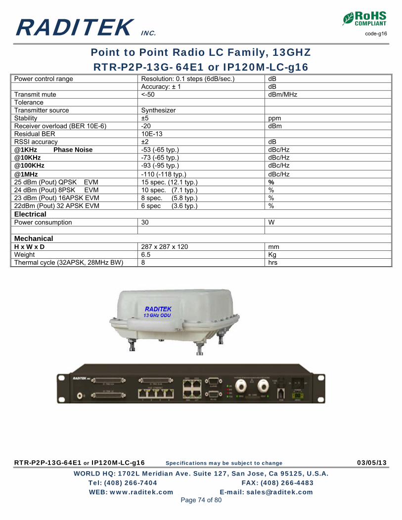
RADITEK INC. code-g16
Point to Point Radio LC Family, 13GHZ RTR-P2P-13G- 64E1 or IP120M-LC-g16
RTR-P2P-13G-64E1 or IP120M-LC-g16 Specifications may be subject to change 03/05/13 WORLD HQ: 1702L Meridian Ave. Suite 127, San Jose, Ca 95125, U.S.A.
Tel: (408) 266-7404 FAX: (408) 266-4483 WEB: www.raditek.com E-mail: [email protected]
Power control range Resolution: 0.1 steps (6dB/sec.) dB Accuracy: ± 1 dB Transmit mute <-50 dBm/MHz Tolerance Transmitter source Synthesizer Stability ±5 ppm Receiver overload (BER 10E-6) -20 dBm Residual BER 10E-13 RSSI accuracy ±2 dB @1KHz Phase Noise -53 (-65 typ.) dBc/Hz @10KHz -73 (-65 typ.) dBc/Hz @100KHz -93 (-95 typ.) dBc/Hz @1MHz -110 (-118 typ.) dBc/Hz 25 dBm (Pout) QPSK EVM 15 spec. (12.1 typ.) % 24 dBm (Pout) 8PSK EVM 10 spec. (7.1 typ.) % 23 dBm (Pout) 16APSK EVM 8 spec. (5.8 typ.) % 22dBm (Pout) 32 APSK EVM 6 spec (3.6 typ.) % Electrical Power consumption 30 W Mechanical H x W x D 287 x 287 x 120 mm Weight 6.5 Kg Thermal cycle (32APSK, 28MHz BW) 8 hrs
Page 74 of 80

RADITEK INC. code-g16
Point to Point Radio LC Family, 13GHZ RTR-P2P-13G- 64E1 or IP120M-LC-g16
RTR-P2P-13G-64E1 or IP120M-LC-g16 Specifications may be subject to change 03/05/13 WORLD HQ: 1702L Meridian Ave. Suite 127, San Jose, Ca 95125, U.S.A.
Tel: (408) 266-7404 FAX: (408) 266-4483 WEB: www.raditek.com E-mail: [email protected]
Antenna Mount
Page 75 of 80

RTR-P2P-23G-160E1 or IP366Mb-LC-g16 Specifications may be subject to change 03/08/13 WORLD HQ: 1702L Meridian Ave. Suite 127, San Jose, Ca 95125, U.S.A.
Tel: (408) 266-7404 FAX: (408) 266-4483 WEB: www.raditek.com E-mail: [email protected]
Features & Benefits
• Licensed Frequency Bands
• Point to Point IP Link
• Very Low Latency Ethernet
• Adaptive Modulation for increased availability
• Internet Ethernet 10/100Base-T
• Low Power Consumption
• Wide Operating Temperature Range
• SNMP (V1,2,3) Management
• Up to 300 Meter separation between IDU and ODU
• Small profile
• Low installed cost
• Carrier class performance
Overview
This is a Full Duplex (FD), 23GHz Point to Point, Low Cost (LC) microwave, radio link.
An IP based Ethernet Radio system, offering Full Duplex (FD) (data rates up to 366 Mbps). The radio supports software configurable capacity selection to 366 Mbps capacity, up to 160 x E1, using 14, 28/30, 40 and 56 MHz channel bandwidths. With QPSK to 256QAM modulation and Advanced, integrated forward Error correction (FEC) provides superior link performance and reliability. This RADIO is ideally suited for: Backhaul networks; including: WiMAX backhaul, ISPs, next generation mobile, and enterprise/campus networks requiring the best solution that exceeds Carrier-Grade Class standards for highest reliability, quality, and environmental compliance at a relatively low price.
• Incorporates digital Channel filtering for the various data bandwidths. • Offers volume capacity and proven performance for applications, worldwide • Represents a new low cost solution of roof/tower installation • Designed to minimize product logistics and overall product life cycle costs. • Connects directly to antennas from many (other) manufacturers. • Optional: Protected (1+1), 2 x (2+0) Capacity, Full Duplex and other configurations
possible with compatible router Standards Compliance
EMC EN 301 489 Operation, ODU ETS 300 019 Class 4.1 Operation , IDU ETS 300 019 Class 3.2 Storage ETS 300 019 Class 1.2 Transportation ETS 300 019 Class 2.3 Safety EN 60950 RF EN 302 217 Water resistance, ODU IEC 60529 (IPX6)
Telecom 23G Point to Point Radio
Up to 366 Mbps, Ethernet, 160E1, Low Cost, Point to Point
Point to Point Radio LC Family, 23 GHz 160E1 / IP 366Mb
Page 76 of 80

RADITEK INC. code-g16
Point to Point Radio Family 23GHZ RTR-P2P-23G-HYBRID-LC-g16
RTR-P2P-23G-160E1 or IP366Mb-LC-g16 Specifications may be subject to change 03/08/13 WORLD HQ: 1702L Meridian Ave. Suite 127, San Jose, Ca 95125, U.S.A.
Tel: (408) 266-7404 FAX: (408) 266-4483 WEB: www.raditek.com E-mail: [email protected]
Key Feature
• Browser based GUI for easy setup and management • Standard IP and Serial Interfaces • Supports NMS & SNMP Benefits
• More cost effective • Quick Deployment • Lowest cost, Licensed bands • Easily Setup and Activated Applications
• Ethernet IP/ to 160E1 • IP Radio Networks • G3/G4 Backhaul • WiMAX /LTE Backhaul Services available
• Technical Support • Installation and Setup • Maintenance • Applications Support • Hardware Support • Extended Warranty
GENERAL Technical Information
RTR-P2P-23G-HYBRID-LC-g16
Operating frequency 23 GHz Range To 20Km Depends on antenna Digital line rate 1000 Mbps (Fast Ethernet) Capacity 3660 Mbps Modulation Options QPSK, 8PSK,16QAM/16APSK,32QAM/32APSK
to 256 QAM Error Correction/coding RS, LDPC
PRODUCT CONFIGURATION:
1+1, HSB, FD, SD
ENVIRONMENTAL: Operating temperature
IDU -5 to 50 ⁰C
ODU, standard
ODU, extended
IDU, Humidity, (ODU) 0 to 95% (100%) Non condensing ( )
Altitude 4500m 15000 feet
Fault and configuration management
Protocol SNMP v1/v2/v3 Interface, electrical Ethernet 10/100 base-T Interface, electrical RJ-45 Local/remote configuration, support Tools WEB LCT Performance monitoring ITU-T REC. G.826 Network management EMS 1000 EOW (Engineering Order Wire) EOW and AUX RS-232
Capacity/Channel Bandwidth
Capacity Modulation Bandwidth (ODU 300) 20-90 Mbps QPSK-256QAM 14MHz 40-180 Mbps QPSK-256QAM 28/30MHz, 60-260 Mbps QPSK-256QAM 40MHz 88-366Mbps QPSK-256QAM 56MHz
Page 77 of 80

RADITEK INC. code-g16
Point to Point Radio Family 23GHZ RTR-P2P-23G-HYBRID-LC-g16
RTR-P2P-23G-160E1 or IP366Mb-LC-g16 Specifications may be subject to change 03/08/13 WORLD HQ: 1702L Meridian Ave. Suite 127, San Jose, Ca 95125, U.S.A.
Tel: (408) 266-7404 FAX: (408) 266-4483 WEB: www.raditek.com E-mail: [email protected]
General. IDU Options LED indicators PWR, IDU, ODU, RAI, LNK Line interface GE IF interface Transmit 350MHz -12 to -8 dBm Receive 140MHz, -8 to -37 dBm IF Cable Connector N Type (f/m) Auxiliary Data Channel interface # 1 Interface RS-232 Line rate, configurable 1.2 to 19.2 Kbps Async Connector type RS-232, 9 PIN D-SUB Alarm I/O External Alarm input 2 x TTL External Alarm output 2 x TTL, 2 x Form C relay Connector 9 pin D-SUB NMS LNA Interface Type 10/100 BaseT Ethernet, RJ45 Electrical Input voltage range -38 to -72 VDC Power consumption <40W, typ. Protective Circuit 6A fuse Mechanical Dimensions 44 x 482 x 300 (1U); 87 x 482 x300 (2U) Weight ~2.8Kg (1U typ.), 5.6Kg/2U typ. Internet E1 Capacity options Configurable to 366Mbps, 10/100/1000baseT Configurable to 160 x E1 (2.048 Mbps) Traffic 4 x GE electrical, 1xGE Optical, 4 RJ45 and 1xSFP SCS168
Connectors 4 x RJ45 Coding type: HDB3; 75Ω unbalanced or 120Ω
balanced. Specifications L2 Switching, VLAN (802.3ac), Flow control (802.3X), QoS (802.1p) Threshold (BER 10E-6) QPSK (28MHz BW) -85 dBm ODU Specifications Frequency 23 GHz Modulation QPSK to 256QAM IF Specification IF frequency, Tx 140 MHz IF frequency, Rx 350 MHz Cable impedance 50 Ω Maximum IF cable length (IDU-ODU) 300 m ODU Interfaces IF cable connectors N type f/m AGC monitor BNC f/m Antenna port EIA rectangular (standard) Refer to ODU system spec. Polarization (field selectable) Vertical (standard), horizontal Antenna mount Direct mount
Power 20 (QPSK)
16 (128QAM) dBm dBm
Power control range Resolution: 0.1 steps (6dB/sec.) dB Accuracy: ± 1 dB Transmit mute <-50 dBm/MHz Transmitter source Synthesizer
Page 78 of 80

RADITEK INC. code-g16
Point to Point Radio Family 23GHZ RTR-P2P-23G-HYBRID-LC-g16
RTR-P2P-23G-160E1 or IP366Mb-LC-g16 Specifications may be subject to change 03/08/13 WORLD HQ: 1702L Meridian Ave. Suite 127, San Jose, Ca 95125, U.S.A.
Tel: (408) 266-7404 FAX: (408) 266-4483 WEB: www.raditek.com E-mail: [email protected]
Stability ±5 ppm Receiver overload (BER 10E-6) -20 dBm Residual BER 10E-13 RSSI accuracy ±2 dB @1KHz Phase Noise -70 dBc/Hz @10KHz -80 dBc/Hz @100KHz -98 dBc/Hz @1MHz -110 dBc/Hz 25 dBm (Pout) QPSK EVM 15 spec. % 24 dBm (Pout) 8PSK EVM 10 spec. % 23 dBm (Pout) 16APSK EVM 8 spec. % 15dBm (Pout) 256 QAM EVM 4 spec. % Electrical Power consumption 35 W Mechanical H x W x D 287 x 287 x 120 mm Weight 6.5 Kg Thermal cycle (32APSK, 28MHz BW) 8 hrs
Page 79 of 80

RADITEK INC. code-g16
Point to Point Radio Family 23GHZ RTR-P2P-23G-HYBRID-LC-g16
RTR-P2P-23G-160E1 or IP366Mb-LC-g16 Specifications may be subject to change 03/08/13 WORLD HQ: 1702L Meridian Ave. Suite 127, San Jose, Ca 95125, U.S.A.
Tel: (408) 266-7404 FAX: (408) 266-4483 WEB: www.raditek.com E-mail: [email protected]
Mounting Detail
Page 80 of 80