Embed Size (px)
Citation preview
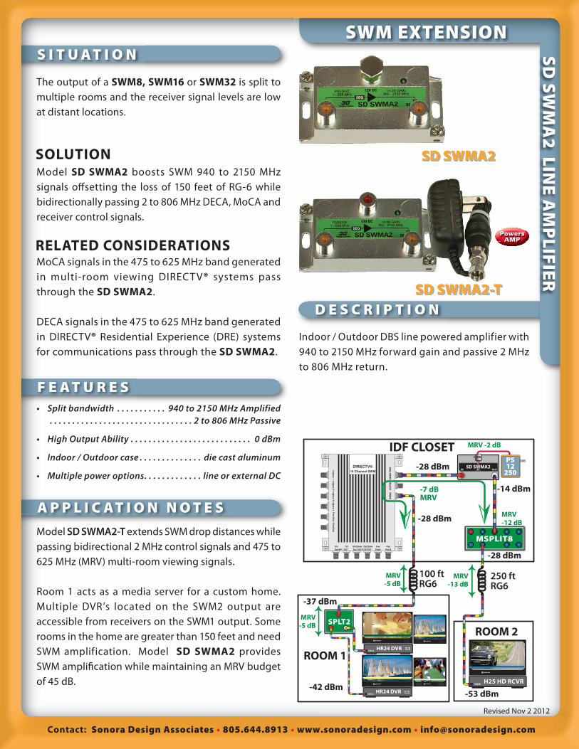
S I T U A T I O N
F E A T U R E S
D E S C R I P T I O N
A P P L I C AT I O N N O T E S
S I T U A T I O N
F E A T U R E S
D E S C R I P T I O N
A P P L I C AT I O N N O T E S
Contact: Sonora Design Associates 805.644.8913 www.sonoradesign.com [email protected]
Revised Nov 2 2012
SOLUTION
RELATED CONSIDERATIONS
The output of a SWM8, SWM16 or SWM32 is split to
multiple rooms and the receiver signal levels are low
at distant locations.
Model SD SWMA2 boosts SWM 940 to 2150 MHz
signals off setting the loss of 150 feet of RG-6 while
bidirectionally passing 2 to 806 MHz DECA, MoCA and
receiver control signals.
MoCA signals in the 475 to 625 MHz band generated
in multi-room viewing DIRECTV® systems pass
through the SD SWMA2.
DECA signals in the 475 to 625 MHz band generated
in DIRECTV® Residential Experience (DRE) systems
for communications pass through the SD SWMA2.
Indoor / Outdoor DBS line powered amplifier with
940 to 2150 MHz forward gain and passive 2 MHz
to 806 MHz return.
• Split bandwidth . . . . . . . . . . . 940 to 2150 MHz Amplified . . . . . . . . . . . . . . . . . . . . . . . . . . . . . . . . 2 to 806 MHz Passive
• High Output Ability . . . . . . . . . . . . . . . . . . . . . . . . . . . 0 dBm
• Indoor / Outdoor case . . . . . . . . . . . . . . die cast aluminum
• Multiple power options . . . . . . . . . . . . . line or external DC
Model SD SWMA2-T extends SWM drop distances while
passing bidirectional 2 MHz control signals and 475 to
625 MHz (MRV) multi-room viewing signals.
Room 1 acts as a media server for a custom home.
Multiple DVR’s located on the SWM2 output are
accessible from receivers on the SWM1 output. Some
rooms in the home are greater than 150 feet and need
SWM amplification. Model SD SWMA2 provides
SWM amplifi cation while maintaining an MRV budget
of 45 dB.
SWM EXTENSIONS
D S
WM
A2
LIN
E A
MP
LIF
IER
SD SWMA2
SD SWMA2-T
Powers AMP
DIRECTV®
16 Channel SWM
SW
M2
Leg
acy 1L
egacy 2
Leg
acy 3L
egacy 4
Flex1O
ut
Flex2O
ut
DC
PW
RS
WM
1PW
R
Sat 99º / 101º18V 13V
Port1Flex
Port2Flex
Sat 103º/110º/119º18V/22kHz 13V/22kHz
MSPLIT8
SPLT2
SWM H25 HD RCVR
100 ft RG6
ROOM 1
250 ft RG6
ROOM 2
SD SWMA2IN OUT
DCPS12
250
MRV-13 dB
MRV-12 dB
MRV -2 dB
MRV-5 dB
MRV-5 dB
IDF CLOSET
DBS2 HR24 DVR
DBS2 HR24 DVR
-28 dBm
-28 dBm
-14 dBm-7 dBMRV
-53 dBm
-37 dBm
-42 dBm
-28 dBm
S P E C I F I C A T I O N SS P E C I F I C A T I O N S
Contact: Sonora Design Associates 805.644.8913 www.sonoradesign.com [email protected]
Revised Nov 2 2012
SWITCH EXTENSIONS
D S
WM
A2
LIN
E A
MP
LIF
IER
Specifi cations ......................... Typical ................... QC Limit
Gain 2 to 806 MHz ............................... -1 dB ................................ -4 dB
940 to 1450 MHz ...........................12 dB .............................. 11 dB
1450 to 2150 MHz ........................15 dB ...............................14 dB
Maximum Output (32 equal transponders) ...............-1 dBm
Maximum Output PowerIM2 with 2 tones @ 0 dBm ..........-54 dBc ................. -52 dBc min.
IM3 with 2 Tones @ 0 dbm .........-56 dBc ................. -54 dBc min.
Pass band Flatness Any 24 MHz band ............................0.1 dB ............................. 0.2 dB
Input Return Loss ...........................12 dB ................................ 9 dB
Output Return Loss ...........................13 dB .............................. 10 dB
Noise Figure ...........................................6 dB ................................ 7 dB
Power Specifi cationsVoltage ...............................................................................10 to 29 VDC
Current .......................................................................98 mA / channel
Model SD SWMA2-T transformer ............................. 12 V 250 mA
Environmental Specifi cationsOperating Environment: ....................................... Indoor/Outdoor
Ambient Temperature .............................................-30º C to +60ºC
Mechanical Specifi cations ..................... ........... SD SWMA2
Dimensions ............................................................. 2.8” x 1.4” x 1.1”
Weight ............................................................................ 4 oz, (0.2 kg)
Master Carton QTY ............................................................ (44 units)
Master Carton Size ......................................................... 11” x 9” x 9”
Master Carton Weight ...................................................21 lb.. (9.5 kg)
Mechanical Specifi cations ..................... ..........SD SWMA2-TWeight ............................................................................ 6 oz, (0.2 kg)
Master Carton QTY ............................................................ (80 units)
Master Carton Size .....................................................12” x 15” x 15”
Master Carton Weight .............................................29.8 lb.. (13.5 kg)
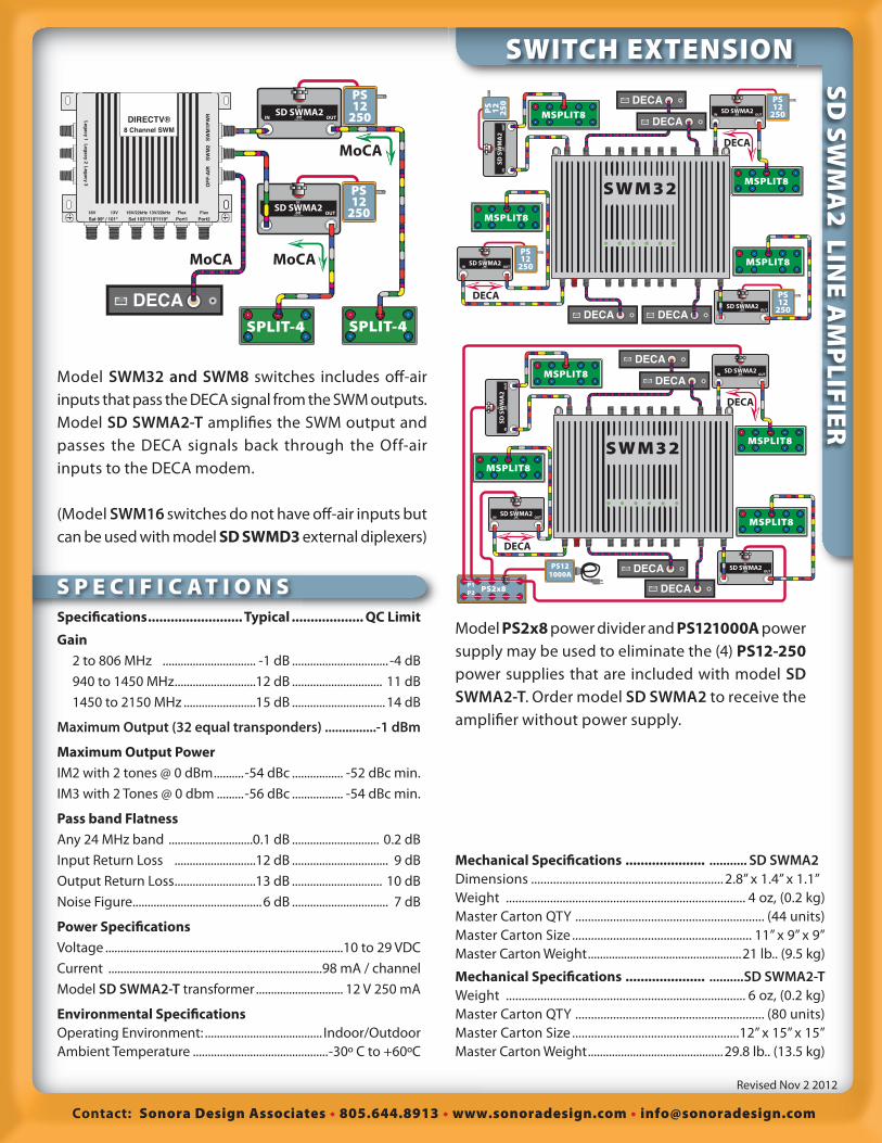
Model SWM32 and SWM8 switches includes off -air
inputs that pass the DECA signal from the SWM outputs.
Model SD SWMA2-T amplifi es the SWM output and
passes the DECA signals back through the Off-air
inputs to the DECA modem.
(Model SWM16 switches do not have off -air inputs but
can be used with model SD SWMD3 external diplexers)
SD S
WM
A2
INO
UT
DC
PS
12
25
0
SD SWMA2IN OUT
DC
PS12
250
SD SWMA2IN OUT
DC
PS12
250
SD SWMA2IN OUT
DC
PS12
250
DECA
MSPLIT8
DECA
MSPLIT8
MSPLIT8
MSPLIT8
DECA
DECA
DECADECA
S W M 3 2SD SWMA2
IN OUT
DC
PS12
250
DECASPLIT-4
MoCA
SPLIT-4
MoCAMoCA
SD SWMA2IN OUT
DC
PS12
250DIRECTV®
8 Channel SWM
OF
F-A
IR
Leg
acy 1L
egacy 2
Leg
acy 3
SW
M2
SW
M1P
WR
Sat 99º / 101º18V 13V
Port1Flex
Port2Flex
Sat 103º/110º/119º18V/22kHz 13V/22kHz
Model PS2x8 power divider and PS121000A power
supply may be used to eliminate the (4) PS12-250power supplies that are included with model SD SWMA2-T. Order model SD SWMA2 to receive the
amplifi er without power supply.
PS2x8P1
P2
PS121000A
SD S
WM
A2
INO
UT
DC
SD SWMA2IN OUT
DC
SD SWMA2IN OUT
DC
SD SWMA2IN OUT
DC
DECA
MSPLIT8
DECA
MSPLIT8
MSPLIT8
MSPLIT8
DECA
DECA
DECA
DECA
S W M 3 2
Contact: Sonora Design Associates 805.644.8913 www.sonoradesign.com [email protected]
Revised Nov 2 2012
3
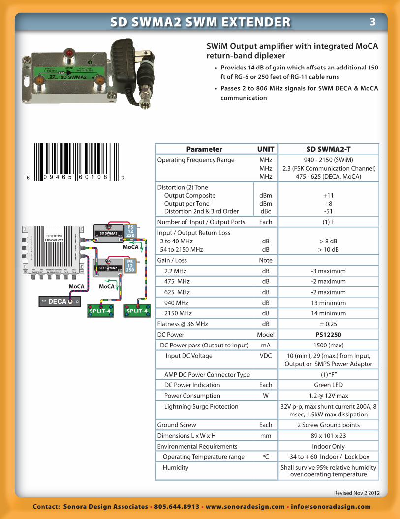
SWiM Output amplifi er with integrated MoCA return-band diplexer • Provides 14 dB of gain which off sets an additional 150
ft of RG-6 or 250 feet of RG-11 cable runs
• Passes 2 to 806 MHz signals for SWM DECA & MoCA communication
Parameter UNIT SD SWMA2-T
Operating Frequency Range MHz
MHz
MHz
940 - 2150 (SWiM)
2.3 (FSK Communication Channel)
475 - 625 (DECA, MoCA)
Distortion (2) Tone
Output Composite
Output per Tone
Distortion 2nd & 3 rd Order
dBm
dBm
dBc
+11
+8
-51
Number of Input / Output Ports Each (1) F
Input / Output Return Loss
2 to 40 MHz
54 to 2150 MHz
dB
dB
> 8 dB
> 10 dB
Gain / Loss Note
2.2 MHz dB -3 maximum
475 MHz dB -2 maximum
625 MHz dB -2 maximum
940 MHz dB 13 minimum
2150 MHz dB 14 minimum
Flatness @ 36 MHz dB ± 0.25
DC Power Model PS12250
DC Power pass (Output to Input) mA 1500 (max)
Input DC Voltage VDC 10 (min.), 29 (max.) from Input,
Output or SMPS Power Adaptor
AMP DC Power Connector Type (1) “F”
DC Power Indication Each Green LED
Power Consumption W 1.2 @ 12V max
Lightning Surge Protection 32V p-p, max shunt current 200A; 8
msec, 1.5kW max dissipation
Ground Screw Each 2 Screw Ground points
Dimensions L x W x H mm 89 x 101 x 23
Environmental Requirements Indoor Only
Operating Temperature range ºC -34 to + 60 Indoor / Lock box
Humidity Shall survive 95% relative humidity over operating temperature
SD SWMA2 SWM EXTENDER
SD SWMA2IN OUT
DC
PS12
250
DECASPLIT-4
MoCA
SPLIT-4
MoCAMoCA
SD SWMA2IN OUT
DC
PS12
250DIRECTV®
8 Channel SWM
OF
F-A
IR
Leg
acy 1L
egacy 2
Leg
acy 3
SW
M2
SW
M1P
WR
Sat 99º / 101º18V 13V
Port1Flex
Port2Flex
Sat 103º/110º/119º18V/22kHz 13V/22kHz
Contact: Sonora Design Associates 805.644.8913 www.sonoradesign.com [email protected]
Revised Nov 2 2012
4SONORA DESIGN POWER SUPPLIES
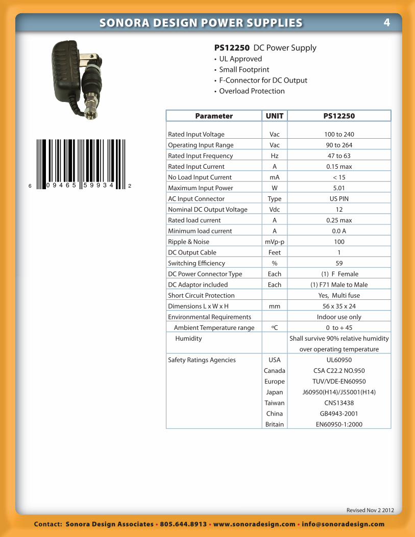
Parameter UNIT PS12250
Rated Input Voltage Vac 100 to 240
Operating Input Range Vac 90 to 264
Rated Input Frequency Hz 47 to 63
Rated Input Current A 0.15 max
No Load Input Current mA < 15
Maximum Input Power W 5.01
AC Input Connector Type US PIN
Nominal DC Output Voltage Vdc 12
Rated load current A 0.25 max
Minimum load current A 0.0 A
Ripple & Noise mVp-p 100
DC Output Cable Feet 1
Switching Effi ciency % 59
DC Power Connector Type Each (1) F Female
DC Adaptor included Each (1) F71 Male to Male
Short Circuit Protection Yes, Multi fuse
Dimensions L x W x H mm 56 x 35 x 24
Environmental Requirements Indoor use only
Ambient Temperature range ºC 0 to + 45
Humidity Shall survive 90% relative humidity
over operating temperature
Safety Ratings Agencies USA
Canada
Europe
Japan
Taiwan
China
Britain
UL60950
CSA C22.2 NO.950
TUV/VDE-EN60950
J60950(H14)/J55001(H14)
CNS13438
GB4943-2001
EN60950-1:2000
PS12250 DC Power Supply
• UL Approved
• Small Footprint
• F-Connector for DC Output
• Overload Protection
Contact: Sonora Design Associates 805.644.8913 www.sonoradesign.com [email protected]
Revised Nov 2 2012
5
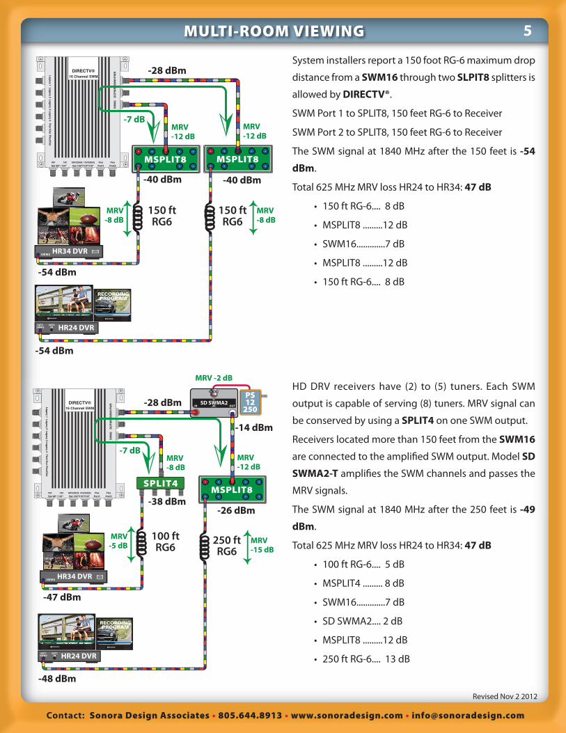
System installers report a 150 foot RG-6 maximum drop
distance from a SWM16 through two SLPIT8 splitters is
allowed by DIRECTV®.
SWM Port 1 to SPLIT8, 150 feet RG-6 to Receiver
SWM Port 2 to SPLIT8, 150 feet RG-6 to Receiver
The SWM signal at 1840 MHz after the 150 feet is -54
dBm.
Total 625 MHz MRV loss HR24 to HR34: 47 dB
• 150 ft RG-6.... 8 dB
• MSPLIT8 .........12 dB
• SWM16.............7 dB
• MSPLIT8 .........12 dB
• 150 ft RG-6.... 8 dB
SWM5 HR34 DVR
RECORDINGPROGRAM
SAT1SWM2
SAT2IN HR24 DVR
MSPLIT8
150 ft RG6
150 ft RG6
MSPLIT8
DIRECTV®
16 Channel SWM
SW
M2
Leg
acy 1L
egacy 2
Leg
acy 3L
egacy 4
Flex1O
ut
Flex2O
ut
DC
PW
RS
WM
1PW
R
Sat 99º / 101º18V 13V
Port1Flex
Port2Flex
Sat 103º/110º/119º18V/22kHz 13V/22kHz
-28 dBm
-40 dBm
-54 dBm
-54 dBm
-40 dBm
-7 dB
MRV-8 dB
MRV-8 dB
MRV-12 dB
MRV-12 dB
SWM5 HR34 DVR
RECORDINGPROGRAM
SAT1SWM2
SAT2IN HR24 DVR
100 ft RG6
250 ft RG6
MSPLIT8
DIRECTV®
16 Channel SWM
SW
M2
Leg
acy 1L
egacy 2
Leg
acy 3L
egacy 4
Flex1O
ut
Flex2O
ut
DC
PW
RS
WM
1PW
R
Sat 99º / 101º18V 13V
Port1Flex
Port2Flex
Sat 103º/110º/119º18V/22kHz 13V/22kHz
SD SWMA2IN OUT
DCPS12
250-28 dBm
-14 dBm
SPLIT4
-38 dBm
-47 dBm
-48 dBm
-26 dBm
-7 dB
MRV-5 dB
MRV-15 dB
MRV-12 dB
MRV-8 dB
MRV -2 dBHD DRV receivers have (2) to (5) tuners. Each SWM
output is capable of serving (8) tuners. MRV signal can
be conserved by using a SPLIT4 on one SWM output.
Receivers located more than 150 feet from the SWM16
are connected to the amplifi ed SWM output. Model SD
SWMA2-T amplifi es the SWM channels and passes the
MRV signals.
The SWM signal at 1840 MHz after the 250 feet is -49
dBm.
Total 625 MHz MRV loss HR24 to HR34: 47 dB
• 100 ft RG-6.... 5 dB
• MSPLIT4 ......... 8 dB
• SWM16.............7 dB
• SD SWMA2.... 2 dB
• MSPLIT8 .........12 dB
• 250 ft RG-6.... 13 dB
MULTI-ROOM VIEWING