Embed Size (px)
Citation preview
Switching Maintenance
1. System Integration Contents 1.1 Introduction to GSM System Elements....................................................................................... 2 1.2. GSM System Element ............................................................................................................... 7 1.3. Subsystem Functions and Integration ..................................................................................... 15
1BCCN2200 © 2007 Bintang CyberFall
Switching Maintenance
1.1. Introduction to GSM System Elements
2BCCN2200 © 2007 Bintang CyberFall
Switching Maintenance
The basis for the standardization of a European cellular system was laid down in the mid 80s. A
team of the CEPT (today ETSI) worked on the standardization of this European cellular system.
The team was led under the name "Group Special Mobile" (GSM). This abbreviation was later
used as standard and changed to "Global System for Mobile Communications". The GSM or DCS
network is operated in a frequency range of 890 to 915 MHz and 835 to 960 MHz or 1710 to 1785
MHz and 1805 to 1880 MHz.
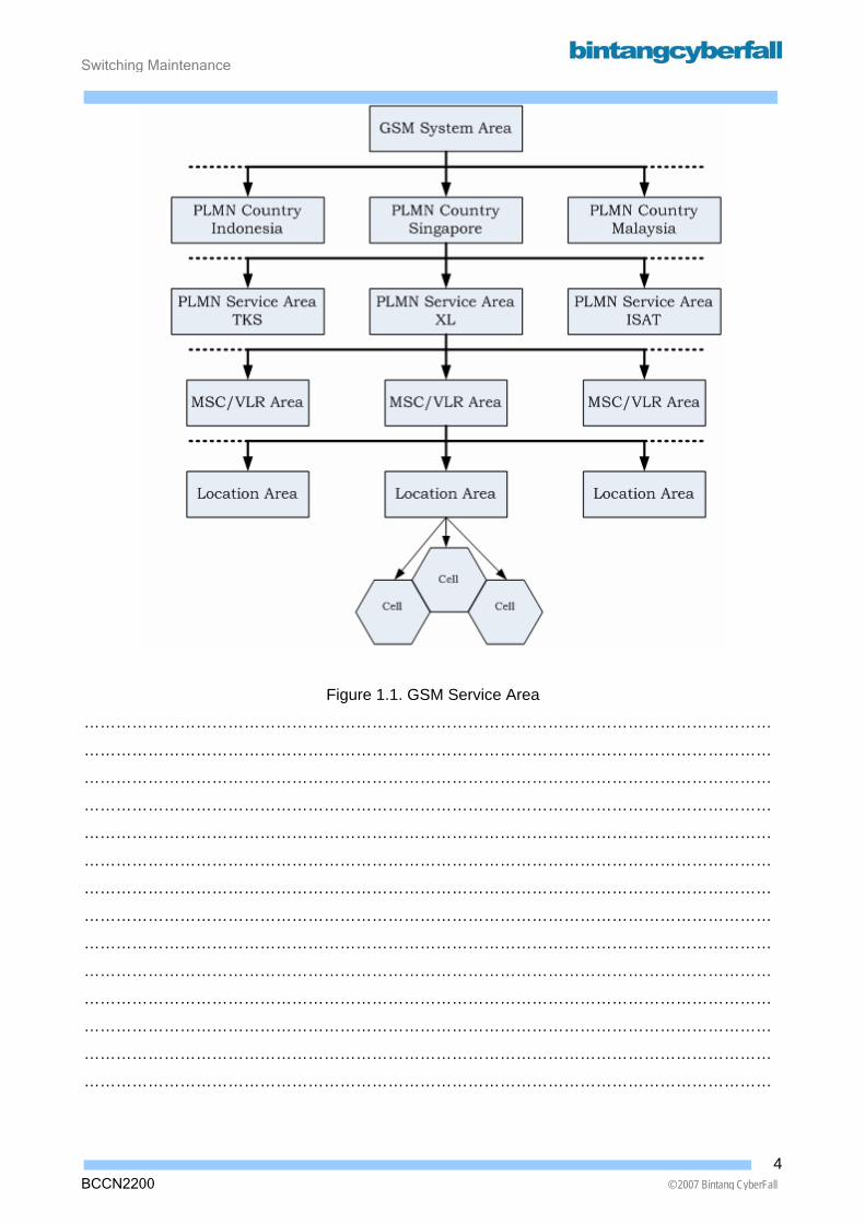
PLMN country (public land mobile network) Several PLMN network operators can appear in a "PLMN country".
A "PLMN country" is unambiguously specified via the selection of a so-called
"country code".
PLMN area A "PLMN area" is as a rule synonymous to PLMN network operator or a PLM network. Several
network operators who organize the "PLMN country" either regionally (e.g. North and South) or
overlapping appear as a rule in a "PLMN country". A PLMN area is unambiguously addressable
via the "network destination code" (NDC) which can be dialed.
MSC area (mobile services switching center) A PLMN normally contains several "MSCareas". An MSC is a "switching center" or switching
equipment for mobile subscribers and has one or several connections to the base station system"
or radio system. An "MSC Area" is unambiguously addressable via dialing information; it cannot
however be dialed by the calling subscriber, as it does not know the location of the subscriber.
Location area A "location area" is an administrative area within an "MSC area" (e.g. an emergency service
number per "location area") and covers several cell broadcast channels (CBCH). A "location area"
is internationally addressable, but it can not be dialed.
Cell A "cell" is the smallest functional area and is covered by a "base station"(BS), i.e. radio station. It
is the physical location of a mobile subscriber. In case of the cell is covered by an omni directional
BS (coverage 360 degrees) the cell contains one frequency pair (one up- and one downlink) and
therefore up to 8 traffic channels.
In case of the cell is subdivided into sectors up 8 X number of sectors traffic channels are possible.
A cell is also internally addressable.
3BCCN2200 © 2007 Bintang CyberFall
Switching Maintenance
Figure 1.1. GSM Service Area
…………………………………………………………………………………………………………………
…………………………………………………………………………………………………………………
…………………………………………………………………………………………………………………
…………………………………………………………………………………………………………………
…………………………………………………………………………………………………………………
…………………………………………………………………………………………………………………
…………………………………………………………………………………………………………………
…………………………………………………………………………………………………………………
…………………………………………………………………………………………………………………
…………………………………………………………………………………………………………………
…………………………………………………………………………………………………………………
…………………………………………………………………………………………………………………
…………………………………………………………………………………………………………………
…………………………………………………………………………………………………………………
4BCCN2200 © 2007 Bintang CyberFall
Switching Maintenance
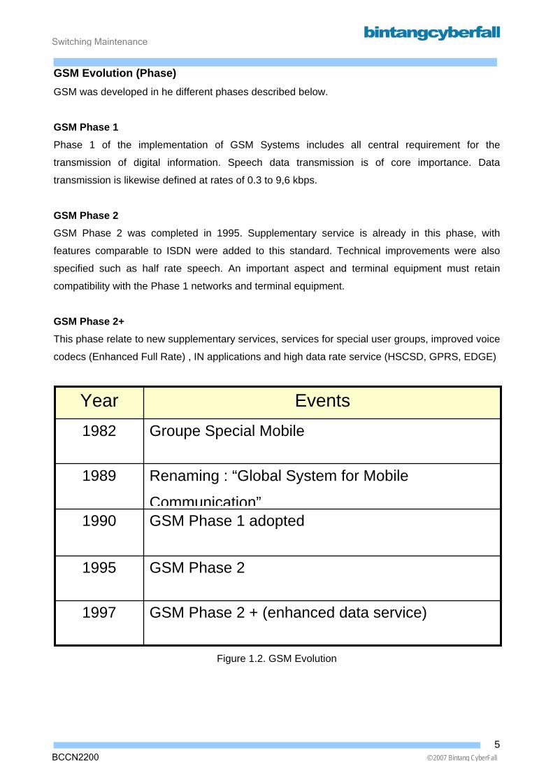
GSM Evolution (Phase) GSM was developed in he different phases described below.
GSM Phase 1 Phase 1 of the implementation of GSM Systems includes all central requirement for the
transmission of digital information. Speech data transmission is of core importance. Data
transmission is likewise defined at rates of 0.3 to 9,6 kbps.
GSM Phase 2 GSM Phase 2 was completed in 1995. Supplementary service is already in this phase, with
features comparable to ISDN were added to this standard. Technical improvements were also
specified such as half rate speech. An important aspect and terminal equipment must retain
compatibility with the Phase 1 networks and terminal equipment.
GSM Phase 2+ This phase relate to new supplementary services, services for special user groups, improved voice
codecs (Enhanced Full Rate) , IN applications and high data rate service (HSCSD, GPRS, EDGE)
GSM Phase 2 + (enhanced data service) 1997
GSM Phase 2 1995
GSM Phase 1 adopted 1990
Renaming : “Global System for Mobile
Communication”
1989
Groupe Special Mobile 1982
Events Year
Figure 1.2. GSM Evolution
5BCCN2200 © 2007 Bintang CyberFall

Switching Maintenance
BCCN2200 © 2007 Bintang CyberFall
Phase Phase Phase
Phase Phase Phase
Service
Figure 1.3. Phase of GSM
…………………………………………………………………………………………………………………
…………………………………………………………………………………………………………………
…………………………………………………………………………………………………………………
…………………………………………………………………………………………………………………
…………………………………………………………………………………………………………………
…………………………………………………………………………………………………………………
…………………………………………………………………………………………………………………
…………………………………………………………………………………………………………………
…………………………………………………………………………………………………………………
…………………………………………………………………………………………………………………
…………………………………………………………………………………………………………………
………………………………………………………………………………………………………………...
Year 1990 1995 1997
Downward-compatible
Speech Connection : - Full Rate (FR)
Data Transfer : (9,6 kbps)
Speech Connection :
- Full Rate (FR)
- Half Rate (HR) Data Transfer : (9,6 kbps)
Supplementary Service
Speech Connection :
- Full Rate (FR)
- Half Rate (HR)
- Enhanced Full Rate (EFR) New Supplementary Service IN Application New Data Transfer :
- HSCSD
- GPRS
- EDGE
6
Switching Maintenance
1.2. GSM System Element
7BCCN2200 © 2007 Bintang CyberFall
Switching Maintenance
BCCN2200 © 2007 Bintang CyberFall
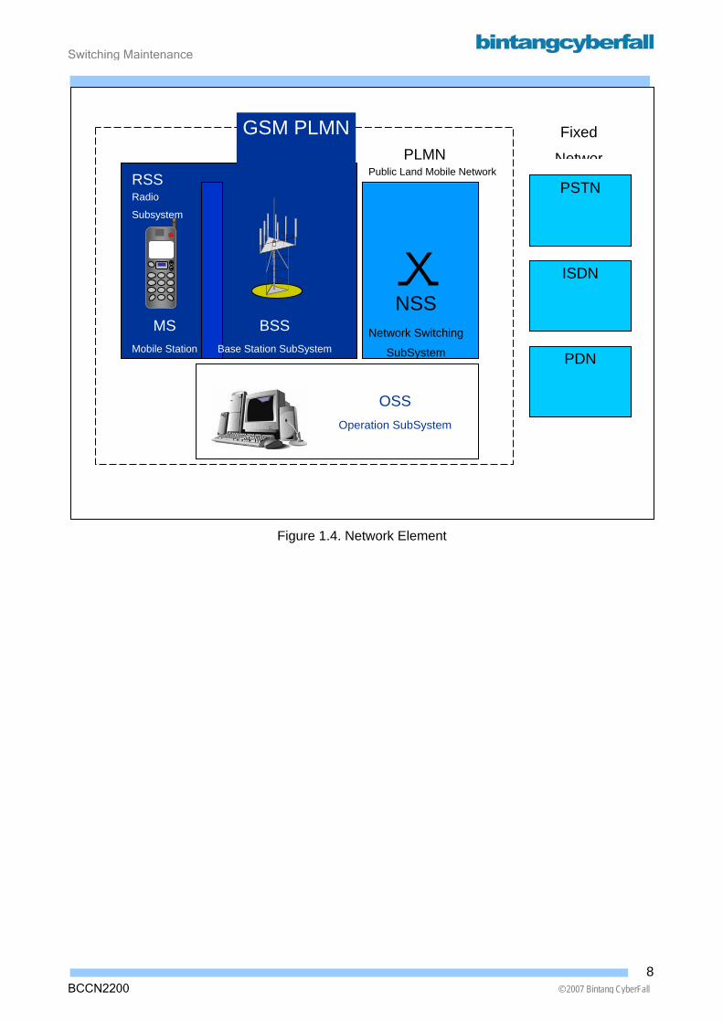
Figure 1.4. Network Element
XNSS
Network Switching
SubSystem
GSM PLMNPLMN
Public Land Mobile Network RSS Radio
Subsystem
MS Mobile Station
PSTN
PDN
ISDN
Fixed
Networ
OSS Operation SubSystem
BSS Base Station SubSystem
8
Switching Maintenance
GSM PLMN
GSM PLMN consists of :
• Network Switching Subsystem (NSS)
• Radio SubSystem (RSS)
• Operation SubSystem (OSS)
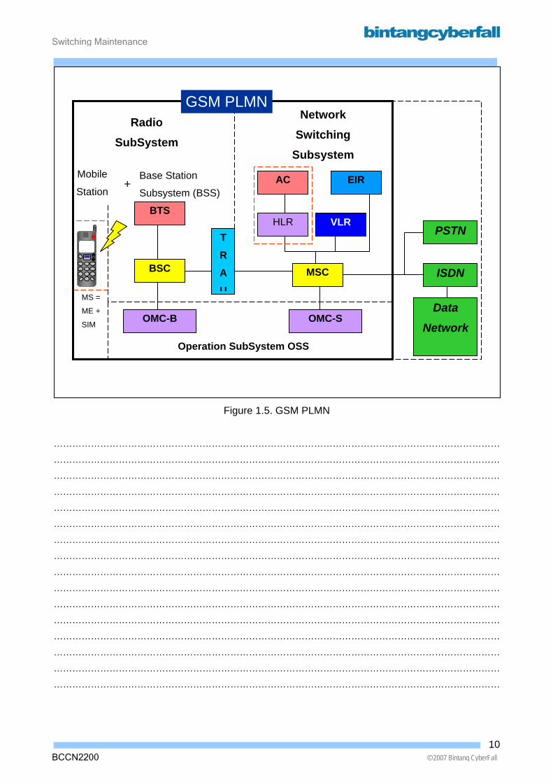
Network Elements The Network Switching Subsystem (NSS) consists of the following functional units :
• Mobile services Switching Center (MSC)
• Visitor Location Register (VLR)
• Home Location Register (HLR)
• Authentication Center (AC)
• Equipment Identity Register (EIR)
The Radio SubSystem (RSS) consists of the Mobile Station (MS) and the Base Station Subsystem
(BSS), which is composed of the following functional units.
• Base Station Controller (BSC)
• Base Transceiver Station (BTS)
• Transcoding and Rate Adaptation Unit (TRAU)
The Operation SubSystem (OSS) consists of :
• Operation & Maintenance Center for BSS
• Operation & Maintenance Center for SSS
9BCCN2200 © 2007 Bintang CyberFall
Switching Maintenance
BCCN2200 © 2007 Bintang CyberFall
Figure 1.5. GSM PLMN
………………………………………………………………………………………………………………………………
………………………………………………………………………………………………………………………………
………………………………………………………………………………………………………………………………
………………………………………………………………………………………………………………………………
………………………………………………………………………………………………………………………………
………………………………………………………………………………………………………………………………
………………………………………………………………………………………………………………………………
………………………………………………………………………………………………………………………………
………………………………………………………………………………………………………………………………
………………………………………………………………………………………………………………………………
………………………………………………………………………………………………………………………………
………………………………………………………………………………………………………………………………
………………………………………………………………………………………………………………………………
………………………………………………………………………………………………………………………………
………………………………………………………………………………………………………………………………
………………………………………………………………………………………………………………………………
BTS
BSC
OMC-B OMC-S
VLR HLR
EIR AC
MSC
T R A U
PSTN
Radio SubSystem
Mobile
Station +
Base Station
Subsystem (BSS)
Operation SubSystem OSS
Network Switching
Subsystem
GSM PLMN
MS =
ME +
SIM
ISDN
Data
Network
10
Switching Maintenance
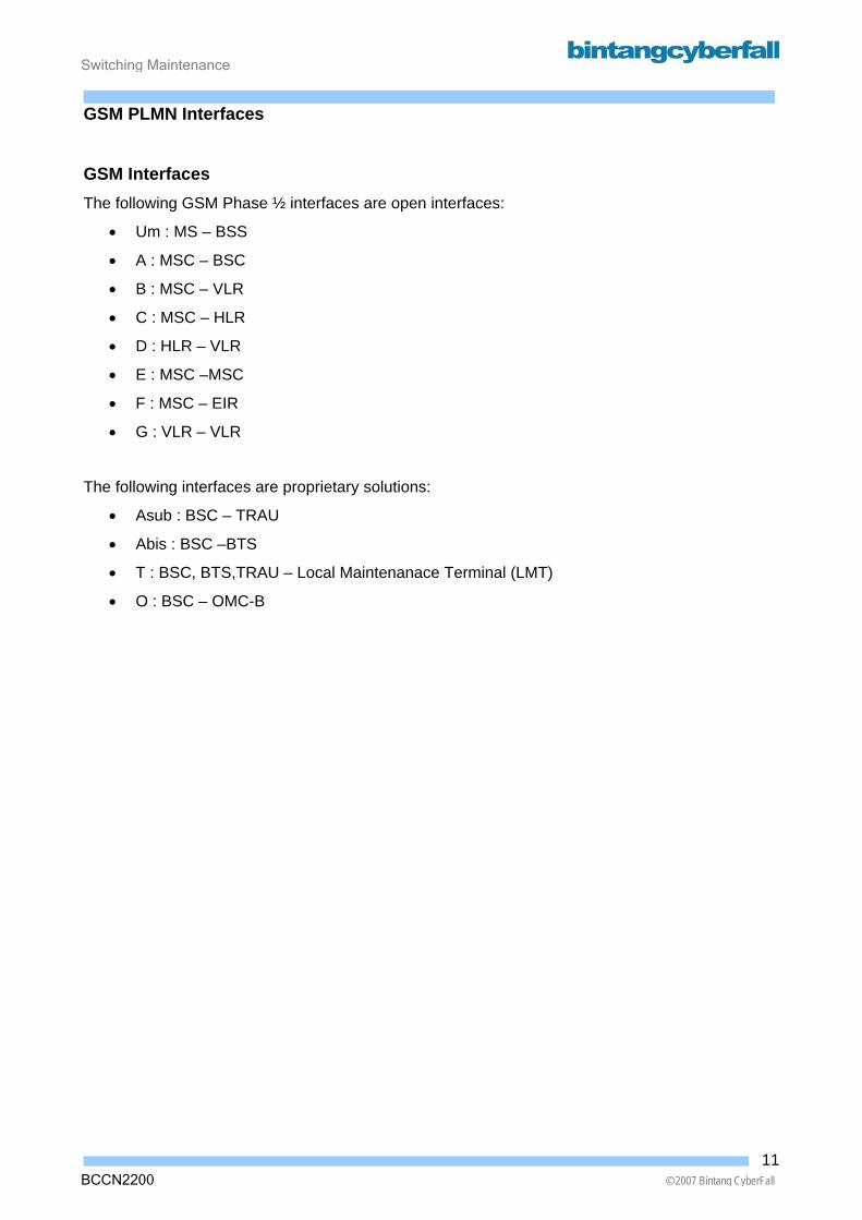
GSM PLMN Interfaces GSM Interfaces The following GSM Phase ½ interfaces are open interfaces:
• Um : MS – BSS
• A : MSC – BSC
• B : MSC – VLR
• C : MSC – HLR
• D : HLR – VLR
• E : MSC –MSC
• F : MSC – EIR
• G : VLR – VLR
The following interfaces are proprietary solutions:
• Asub : BSC – TRAU
• Abis : BSC –BTS
• T : BSC, BTS,TRAU – Local Maintenanace Terminal (LMT)
• O : BSC – OMC-B
11BCCN2200 © 2007 Bintang CyberFall
Switching Maintenance
BCCN2200 © 2007 Bintang CyberFall
GSM PLMN Interface
Figure 1.6. GSM PLMN Interfaces
…………………………………………………………………………………………………………………
…………………………………………………………………………………………………………………
…………………………………………………………………………………………………………………
…………………………………………………………………………………………………………………
…………………………………………………………………………………………………………………
…………………………………………………………………………………………………………………
…………………………………………………………………………………………………………………
…………………………………………………………………………………………………………………
…………………………………………………………………………………………………………………
…………………………………………………………………………………………………………………
…………………………………………………………………………………………………………………
…………………………………………………………………………………………………………………
…………………………………………………………………………………………………………………
…………………………………………………………………………………………………………………
T
MS
BTS BSC TRAU
VLR
• Phase 1/2 • Without GPRS
AC
LM
LM
LM
OMC -
Um Abis Asub
C
B
F
EIR
D T T
O
AHLR MSC
12
Switching Maintenance
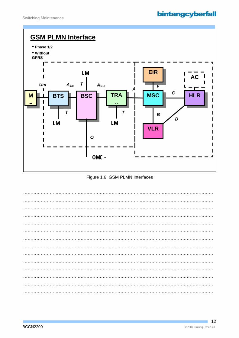
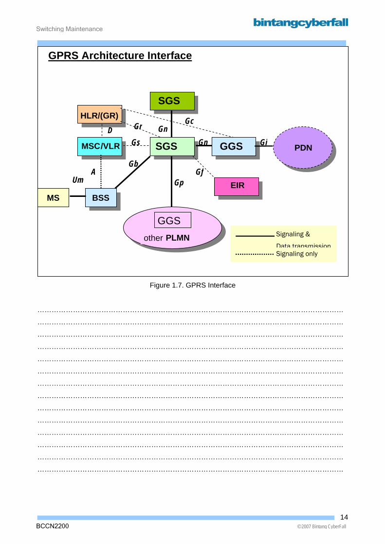
GPRS Interfaces The following GPRS interfaces :
• Gn : SGSN – SGSN
• Gs : SGSN – MSC/VLR
• Gb : SGSN – BSC
• Gc : GGSN – HLR
• Gf : GGSN – EIR
• Gp : SGSN – GGSN (other PLMN)
13BCCN2200 © 2007 Bintang CyberFall
Switching Maintenance
GPRS Architecture Interface
BCCN2200 © 2007 Bintang CyberFall
Figure 1.7. GPRS Interface
…………………………………………………………………………………………………………………
…………………………………………………………………………………………………………………
…………………………………………………………………………………………………………………
…………………………………………………………………………………………………………………
…………………………………………………………………………………………………………………
…………………………………………………………………………………………………………………
…………………………………………………………………………………………………………………
…………………………………………………………………………………………………………………
…………………………………………………………………………………………………………………
…………………………………………………………………………………………………………………
…………………………………………………………………………………………………………………
…………………………………………………………………………………………………………………
…………………………………………………………………………………………………………………
…………………………………………………………………………………………………………………
MS BSS
SGS GGS PDN
GGSother PLMN
MSC /VLR
HLR/(GR)SGS
Gp
Gc
EIR Gf
Gi Gr
Gn
Gb Um
Gs
A
GnD
Signaling &
Signaling only Data transmission
14
Switching Maintenance
1.3. Subsystem Functions and Integration
15BCCN2200 © 2007 Bintang CyberFall
Switching Maintenance
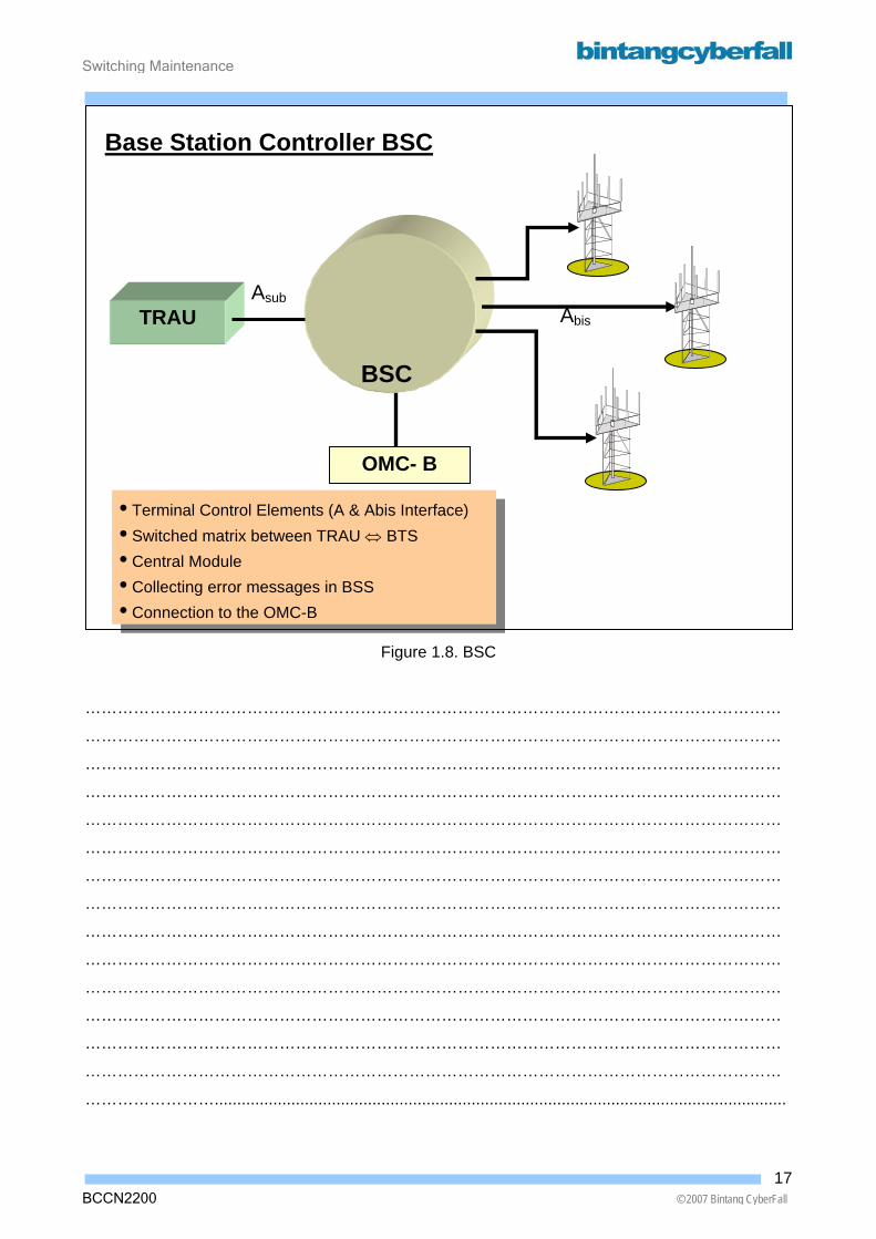
Base Station Subsystem (BSS) The BSS consists of the following network elements :
• BSC : Base Station Controller
• BTS : Base Transceiver Station
• TRAU : Transcoding and Rate Adaptation Rate
Base Station Controller (BSC) The Base Station Controller(BSC) is the controlling element, the heart and center element of the
BSS.
BSC functions :
• Terminal Control Element (A & Abis Interface)
• Switched matrix between TRAU ⇔ BTS
• Central Module
• Collecting error messages in BSS
• Connection to the OMC-B
• Database storage
16BCCN2200 © 2007 Bintang CyberFall
Switching Maintenance
BCCN2200 © 2007 Bintang CyberFall
Figure 1.8. BSC
…………………………………………………………………………………………………………………
…………………………………………………………………………………………………………………
…………………………………………………………………………………………………………………
…………………………………………………………………………………………………………………
…………………………………………………………………………………………………………………
…………………………………………………………………………………………………………………
…………………………………………………………………………………………………………………
…………………………………………………………………………………………………………………
…………………………………………………………………………………………………………………
…………………………………………………………………………………………………………………
…………………………………………………………………………………………………………………
…………………………………………………………………………………………………………………
…………………………………………………………………………………………………………………
…………………………………………………………………………………………………………………
……………………...............................................................................................................................
TRAU
Base Station Controller BSC
• Terminal Control Elements (A & Abis Interface) • Switched matrix between TRAU ⇔ BTS • Central Module • Collecting error messages in BSS • Connection to the OMC-B
OMC- B
AsubAbis
BSC
17
Switching Maintenance
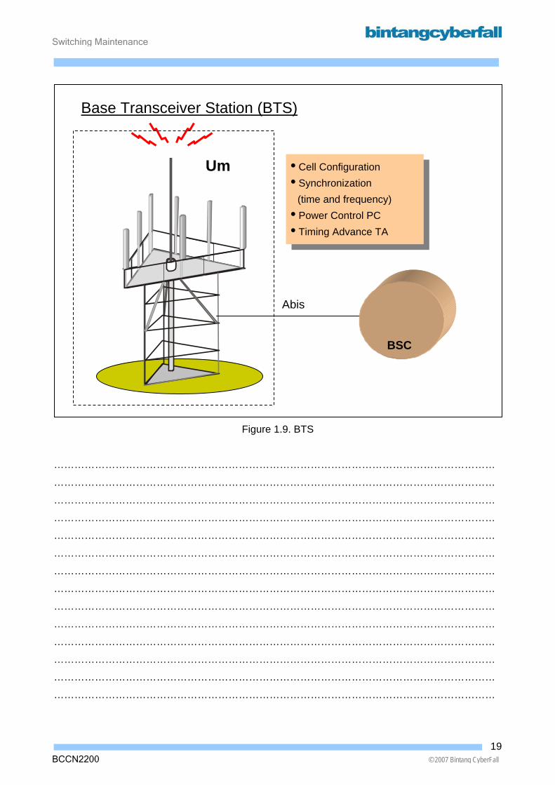
Base Transceiver Station (BTS) The BTS provides the physical connection of an MS to the network in from of the Air Interface. On
the other side, towards the NSS, the BTS is connected to the BSC via the Abis Interface.
Functions:
• Cell Configuration, Standard Cell, Umbrella Cell, Sectorized Cell
• Synchronization: Providing of mobile stations with frequency and time synchronization
information.
• Power Control : Control the power level of BTS and MS
• Timing Advance (TA): Calculation of the distance of the MS from the BTS, The MS are
informed of necessary transmission advance.
18BCCN2200 © 2007 Bintang CyberFall
Switching Maintenance
Um • Cell Configuration • Synchronization (time and frequency) • Power Control PC • Timing Advance TA
Base Transceiver Station (BTS)
BSC
Abis
Figure 1.9. BTS
…………………………………………………………………………………………………………………
…………………………………………………………………………………………………………………
…………………………………………………………………………………………………………………
…………………………………………………………………………………………………………………
…………………………………………………………………………………………………………………
…………………………………………………………………………………………………………………
…………………………………………………………………………………………………………………
…………………………………………………………………………………………………………………
…………………………………………………………………………………………………………………
…………………………………………………………………………………………………………………
…………………………………………………………………………………………………………………
…………………………………………………………………………………………………………………
…………………………………………………………………………………………………………………
…………………………………………………………………………………………………………………
19BCCN2200 © 2007 Bintang CyberFall
Switching Maintenance
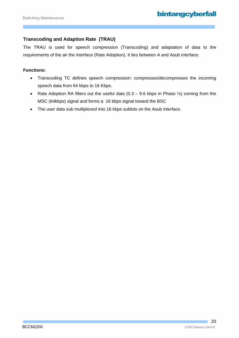
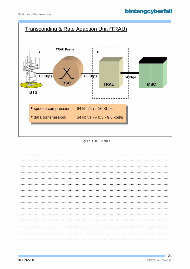
Transcoding and Adaption Rate (TRAU) The TRAU is used for speech compression (Transcoding) and adaptation of data to the
requirements of the air the interface (Rate Adoption). It lies between A and Asub interface.
Functions:
• Transcoding TC defines speech compression: compresses/decompresses the incoming
speech data from 64 kbps to 16 Kbps.
• Rate Adoption RA filters out the useful data (0.3 – 9.6 kbps in Phase ½) coming from the
MSC (64kbps) signal and forms a 16 kbps signal toward the BSC
• The user data sub multiplexed into 16 kbps sublots on the Asub interface.
20BCCN2200 © 2007 Bintang CyberFall
Switching Maintenance
BCCN2200 © 2007 Bintang CyberFall
Figure 1.10. TRAU
…………………………………………………………………………………………………………………
…………………………………………………………………………………………………………………
…………………………………………………………………………………………………………………
…………………………………………………………………………………………………………………
…………………………………………………………………………………………………………………
…………………………………………………………………………………………………………………
…………………………………………………………………………………………………………………
…………………………………………………………………………………………………………………
…………………………………………………………………………………………………………………
…………………………………………………………………………………………………………………
…………………………………………………………………………………………………………………
…………………………………………………………………………………………………………………
…………………………………………………………………………………………………………………
…………………………………………………………………………………………………………………
…………………………………………………………………………………………………………………
• speech compression: 64 kbit/s ↔ 16 Kbps
• data transmission: 64 kbit/s ↔ 0.3 - 9.6 kbit/s
Transconding & Rate Adaption Unit (TRAU)
MSC TRAU BSC
BTS
64 Kbps 16 Kbps16 Kbps
TRAU Frame
21

Switching Maintenance
The Network Switching Subsystem (NSS)
The NSS plays the central part in every mobile network. While the BSS provides the radio access
for the MS, the various network elements within the NSS assume responsibility for the complete
set of control and database functions required to set up call connections using one or more of
these features. (Encryption, Authentication & Roaming)
To satisfy those tasks, the NSS consists of the following :
• Mobile Switching Center (MSC)
• Home Location Register (HLR)
• Visitor Location Register (VLR)
• Equipment Identification Register (EIR)
The Subsystems are interconnected directly or indirectly via the worldwide SS7 network. The
network topology of the NSS is more flexible than the hierarchical structure of BSS. Several MSC
may, for example, use one common VLR, the use of an EIR is optional and the required numbers
of subscribers determines the required number of HLR.
Mobile Switching Center (MSC) The MSC handles connection tasks in the PLMN, i.e. set up of circuit connections to the BSS,
between each other and other networks (PSTN). The MSC visited by a customer is described as a
Visitor MSC (VMSC). A MSC which represents an interface to other networks, is called Gateway
MSC (GMSC).
Functions:
• NSS Center
• Serve Several BSC
• Always associated with VLR
• Set-up & switching of user traffic & signaling
• Gateway MSC: Gateway to external networks
22BCCN2200 © 2007 Bintang CyberFall

Switching Maintenance
BCCN2200 © 2007 Bintang CyberFall
Figure 1.11. MSC
…………………………………………………………………………………………………………………
…………………………………………………………………………………………………………………
…………………………………………………………………………………………………………………
…………………………………………………………………………………………………………………
…………………………………………………………………………………………………………………
…………………………………………………………………………………………………………………
…………………………………………………………………………………………………………………
…………………………………………………………………………………………………………………
…………………………………………………………………………………………………………………
…………………………………………………………………………………………………………………
…………………………………………………………………………………………………………………
…………………………………………………………………………………………………………………
…………………………………………………………………………………………………………………
…………………………………………………………………………………………………………………..
• NSS Center
• Serves Several BSC
• Always associated with VLR
• Set-up & switching of user traffic & signaling
Mobile Switching Center (MSC)
VLR
Visitor Location Register
MSC
GMSC External
Network
23
Switching Maintenance
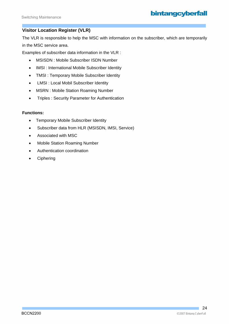
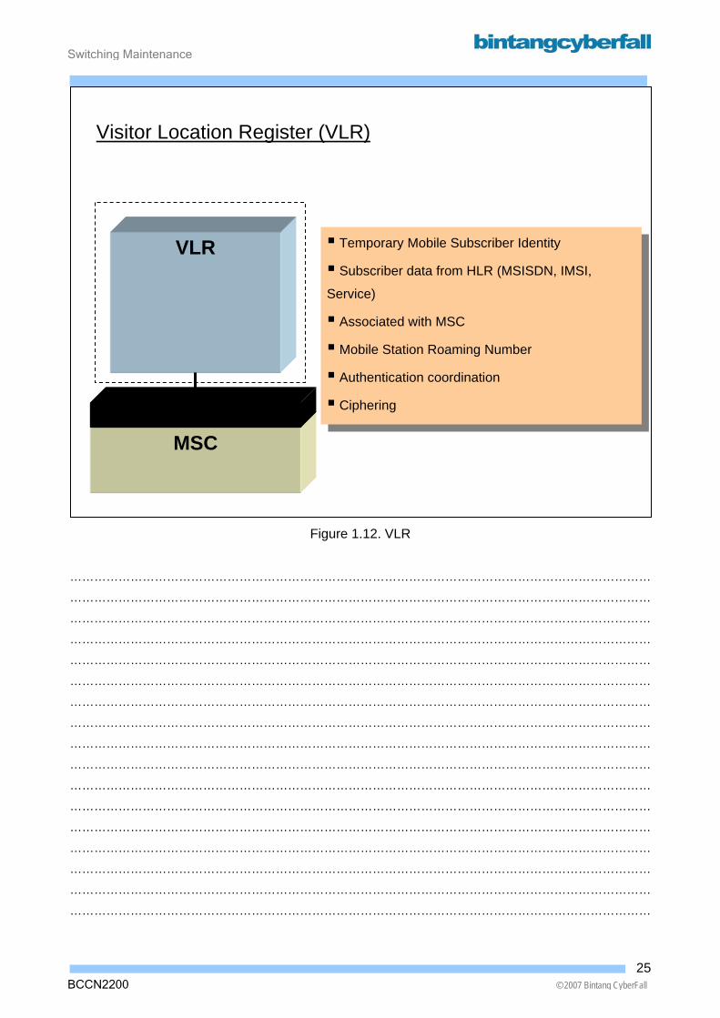
Visitor Location Register (VLR) The VLR is responsible to help the MSC with information on the subscriber, which are temporarily
in the MSC service area.
Examples of subscriber data information in the VLR :
• MSISDN : Mobile Subscriber ISDN Number
• IMSI : International Mobile Subscriber Identity
• TMSI : Temporary Mobile Subscriber Identity
• LMSI : Local Mobil Subscriber Identity
• MSRN : Mobile Station Roaming Number
• Triples : Security Parameter for Authentication
Functions:
• Temporary Mobile Subscriber Identity
• Subscriber data from HLR (MSISDN, IMSI, Service)
• Associated with MSC
• Mobile Station Roaming Number
• Authentication coordination
• Ciphering
24BCCN2200 © 2007 Bintang CyberFall
Switching Maintenance
BCCN2200 © 2007 Bintang CyberFall
Figure 1.12. VLR
………………………………………………………………………………………………………………………………
………………………………………………………………………………………………………………………………
………………………………………………………………………………………………………………………………
………………………………………………………………………………………………………………………………
………………………………………………………………………………………………………………………………
………………………………………………………………………………………………………………………………
………………………………………………………………………………………………………………………………
………………………………………………………………………………………………………………………………
………………………………………………………………………………………………………………………………
………………………………………………………………………………………………………………………………
………………………………………………………………………………………………………………………………
………………………………………………………………………………………………………………………………
………………………………………………………………………………………………………………………………
………………………………………………………………………………………………………………………………
………………………………………………………………………………………………………………………………
………………………………………………………………………………………………………………………………
………………………………………………………………………………………………………………………………
Temporary Mobile Subscriber Identity
Subscriber data from HLR (MSISDN, IMSI,
Service)
Associated with MSC
Mobile Station Roaming Number
Authentication coordination
Ciphering
Visitor Location Register (VLR)
MSC
VLR
25
Switching Maintenance
Home Location Register (HLR) The Home Location Register (HLR) is the main and semi permanent data base of the mobile
subscriber and central storage for data base subscriber.
The HLR is always associated with an Authentication Center (AC).
The HLR performs sends data to the VLR.
Authentication Center (AC) An Authentication Center (AC) contains all necessary means, keys and algorithms for the creation
of security related authorization parameters, the names is Triples.
The Triples are created on VLR request and delivered via HLR to the VLR. An AC is always
associated with HLR.
26BCCN2200 © 2007 Bintang CyberFall

Switching Maintenance
BCCN2200 © 2007 Bintang CyberFall
Figure 1.13. HLR – AC
………………………………………………………………………………………………………………………………
………………………………………………………………………………………………………………………………
………………………………………………………………………………………………………………………………
………………………………………………………………………………………………………………………………
………………………………………………………………………………………………………………………………
………………………………………………………………………………………………………………………………
………………………………………………………………………………………………………………………………
………………………………………………………………………………………………………………………………
………………………………………………………………………………………………………………………………
………………………………………………………………………………………………………………………………
………………………………………………………………………………………………………………………………
………………………………………………………………………………………………………………………………
………………………………………………………………………………………………………………………………
………………………………………………………………………………………………………………………………
………………………………………………………………………………………………………………………………
………………………………………………………………………………………………………………………………
………………………………………………………………………………………………………………………………
Home Location Register
• Central storage of subscriber data
• Send data to VLR (eg. Triples Request)
• Associated with AC
• Semi-permanent data : MSISDN, IMSI, &
Service
Authentication Center
• Generation of triples (VLR request) • Associated with HLR
Authentication Center (AC)
Home Location Register (HLR)
AC
HLR
27

Switching Maintenance
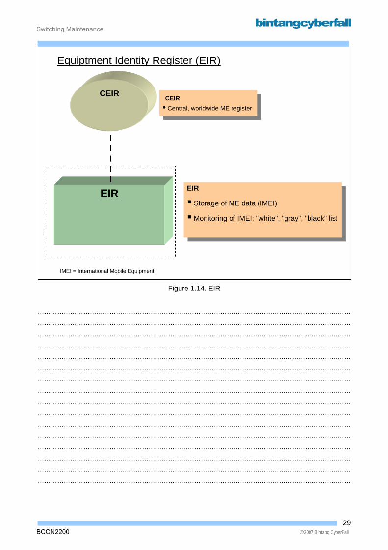
Equipment Identity Register (EIR) The Equipment Identity Register (EIR) contains the mobile equipment identity: International Mobile
Equipment Identity (IMEI). An IMEI clearly identifies a unique Mobile Equipment (ME) and contains
information about the place of manufacture, device type and the serial number of the equipment.
EIR are an optional feature in GSM.
There is having three lists to be observed and to be blocked equipment (WHITE – GRAY –
BLACK).
A Common EIR (CEIR) in Ireland enables the world-wide identification of stolen mobile equipment.
28BCCN2200 © 2007 Bintang CyberFall
Switching Maintenance
BCCN2200 © 2007 Bintang CyberFall
Figure 1.14. EIR
………………………………………………………………………………………………………………………………
………………………………………………………………………………………………………………………………
………………………………………………………………………………………………………………………………
………………………………………………………………………………………………………………………………
………………………………………………………………………………………………………………………………
………………………………………………………………………………………………………………………………
………………………………………………………………………………………………………………………………
………………………………………………………………………………………………………………………………
………………………………………………………………………………………………………………………………
………………………………………………………………………………………………………………………………
………………………………………………………………………………………………………………………………
………………………………………………………………………………………………………………………………
………………………………………………………………………………………………………………………………
………………………………………………………………………………………………………………………………
………………………………………………………………………………………………………………………………
………………………………………………………………………………………………………………………………
EIR
Storage of ME data (IMEI)
Monitoring of IMEI: "white", "gray", "black" list
CEIR • Central, worldwide ME register
EIR
Equiptment Identity Register (EIR)
CEIR
IMEI = International Mobile Equipment
29

Switching Maintenance
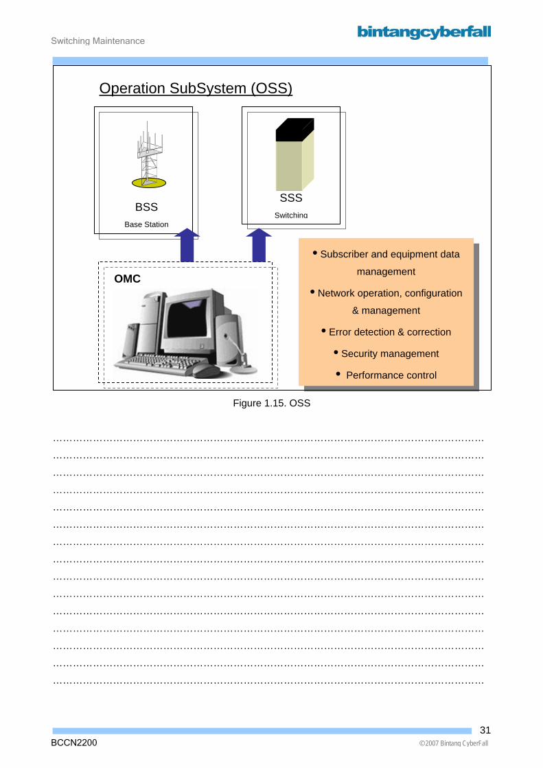
Operation SubSystem (OSS) The functions of the OSS are performed:
• Subscriber and equipment data management
• Network operation, configuration & management
• Error detection & correction
• Security management
• Performance control
30BCCN2200 © 2007 Bintang CyberFall
Switching Maintenance
BCCN2200 © 2007 Bintang CyberFall
Figure 1.15. OSS
…………………………………………………………………………………………………………………
…………………………………………………………………………………………………………………
…………………………………………………………………………………………………………………
…………………………………………………………………………………………………………………
…………………………………………………………………………………………………………………
…………………………………………………………………………………………………………………
…………………………………………………………………………………………………………………
…………………………………………………………………………………………………………………
…………………………………………………………………………………………………………………
…………………………………………………………………………………………………………………
…………………………………………………………………………………………………………………
…………………………………………………………………………………………………………………
…………………………………………………………………………………………………………………
…………………………………………………………………………………………………………………
…………………………………………………………………………………………………………………
• Subscriber and equipment data
management
• Network operation, configuration
& management
• Error detection & correction
• Security management
• Performance control
Operation SubSystem (OSS)
SSS Switchin
BSS Base Station
OMC
g
31
Switching Maintenance
2. Operation, Administration, and Maintenance Concept
Contents 2.1. Alarm Concept ........................................................................................................................... 2
2.1.1. Alarm and Message .......................................................................................................... 10 2.1.2. Alarm Clearance ............................................................................................................... 26 2.1.3. Escalation.......................................................................................................................... 30
2.2. Language and Communication................................................................................................ 32 2.2.1. Communication Interfaces ................................................................................................ 34 2.2.2. Commands and Syntaxes ................................................................................................. 36
2.3. Project Specific Documents..................................................................................................... 48 2.3.1. Tools and Documents ....................................................................................................... 51
1BCCN2200 © 2007 Bintang CyberFall

Switching Maintenance
2.1. Alarm Concept
2BCCN2200 © 2007 Bintang CyberFall

Switching Maintenance
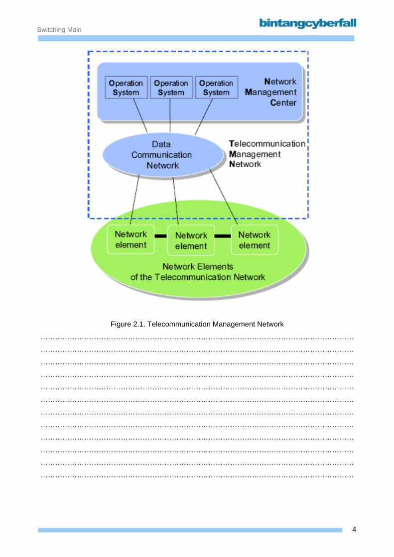
A telecommunication network consists of different transmission and switching equipment and
devices. It offers different services to customers. ITU-T has specified the concept of a
Telecommunication Management Network (TMN) to provide management support for network
operators.
The simplified physical architecture of a TMN has two components:
• The operation systems (OS) provide the man-machine interface for conducting
management functions.
The functions are generally located in the Network Management Center (NMC).
• The Data Communication Network (DCN) connects the operation systems to the individual
network elements (NE) of the telecommunications network.
3BCCN2200 © 2007 Bintang CyberFall
Switching Maintenance
Figure 2.1. Telecommunication Management Network
…………………………………………………………………………………………………………………
…………………………………………………………………………………………………………………
…………………………………………………………………………………………………………………
…………………………………………………………………………………………………………………
…………………………………………………………………………………………………………………
…………………………………………………………………………………………………………………
…………………………………………………………………………………………………………………
…………………………………………………………………………………………………………………
…………………………………………………………………………………………………………………
…………………………………………………………………………………………………………………
…………………………………………………………………………………………………………………
…………………………………………………………………………………………………………………
4BCCN2200 © 2007 Bintang CyberFall
Switching Maintenance
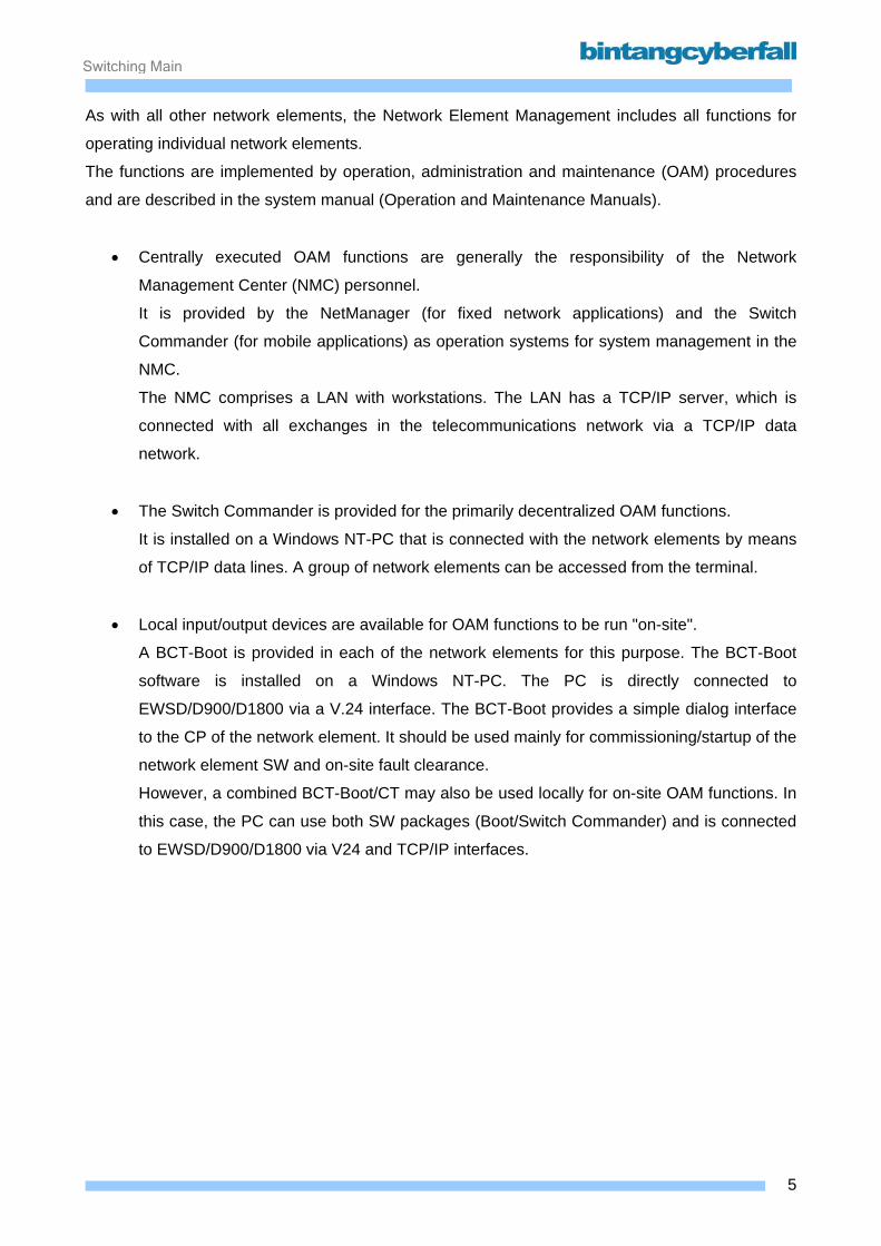
As with all other network elements, the Network Element Management includes all functions for
operating individual network elements.
The functions are implemented by operation, administration and maintenance (OAM) procedures
and are described in the system manual (Operation and Maintenance Manuals).
• Centrally executed OAM functions are generally the responsibility of the Network
Management Center (NMC) personnel.
It is provided by the NetManager (for fixed network applications) and the Switch
Commander (for mobile applications) as operation systems for system management in the
NMC.
The NMC comprises a LAN with workstations. The LAN has a TCP/IP server, which is
connected with all exchanges in the telecommunications network via a TCP/IP data
network.
• The Switch Commander is provided for the primarily decentralized OAM functions.
It is installed on a Windows NT-PC that is connected with the network elements by means
of TCP/IP data lines. A group of network elements can be accessed from the terminal.
• Local input/output devices are available for OAM functions to be run "on-site".
A BCT-Boot is provided in each of the network elements for this purpose. The BCT-Boot
software is installed on a Windows NT-PC. The PC is directly connected to
EWSD/D900/D1800 via a V.24 interface. The BCT-Boot provides a simple dialog interface
to the CP of the network element. It should be used mainly for commissioning/startup of the
network element SW and on-site fault clearance.
However, a combined BCT-Boot/CT may also be used locally for on-site OAM functions. In
this case, the PC can use both SW packages (Boot/Switch Commander) and is connected
to EWSD/D900/D1800 via V24 and TCP/IP interfaces.
5BCCN2200 © 2007 Bintang CyberFall
Switching Maintenance
Figure 2.2. TNM Components
…………………………………………………………………………………………………………………
…………………………………………………………………………………………………………………
…………………………………………………………………………………………………………………
…………………………………………………………………………………………………………………
…………………………………………………………………………………………………………………
…………………………………………………………………………………………………………………
…………………………………………………………………………………………………………………
…………………………………………………………………………………………………………………
…………………………………………………………………………………………………………………
…………………………………………………………………………………………………………………
…………………………………………………………………………………………………………………
………………………………………………………………………………………………………………...
6BCCN2200 © 2007 Bintang CyberFall
Switching Maintenance
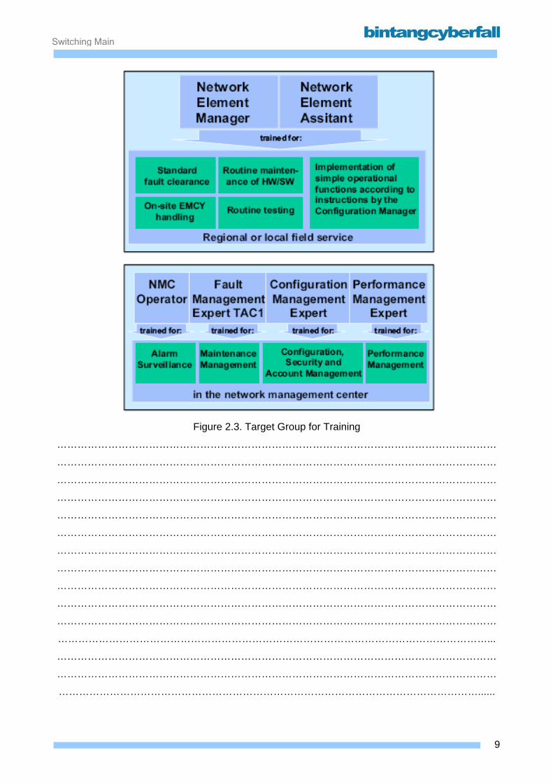
The training program has a modular structure and is oriented toward target groups.
The displayed assignment of the target groups to the NMC and regional OMCs can be modified by
specific solutions for individual network operators.
Centralized personnel in the NMC:
• NMC operator:
Performs alarm surveillance in the NMC and decides what department of the network
operator is to be notified of the alarm.
• Fault Management Expert (FME):
The fault management expert represents the technical assistance center TAC1 of the
network operator in the NMC. The FME is responsible for the central control function for all
maintenance activities in the network elements. He/she supports the field service and
performs special fault clearance if a fault cannot be resolved by the standard field service
fault clearance procedures. Moreover, this person is the single point of contact for the
network operator for support by the technical support center (TSC).
• Configuration Management Expert (CME):
The configuration management expert in the NMC is responsible for all configuration
functions in the network elements. This includes modification of the network element
database based on decisions taken by the planning department/service management as
well as clearance of malfunctions in the network (e.g., signaling problems).
In addition to the actual configuration management, the CME also implements the account
and security management functions.
• Performance Management Expert (PME):
Performs all performance management functions in the NMC.
Field service personnel in regional OMCs/exchanges:
• Network Element Manager (NEM):
Performs all standard functions for HW maintenance, SW safeguarding and routine testing.
Alarms are forwarded to the NEM from the NMC for this purpose. Should the NEM meet
with no success in clearing faults (e.g., major faults in emergency situations), he/she refers
to the fault management expert in the TAC1.
7BCCN2200 © 2007 Bintang CyberFall
Switching Maintenance
Moreover, the NEM can carry out simple database modifications according to instructions
by the CME.
• Network Element Assistant (NEA):
Supports the network element manager (NEM) during fault clearance (e.g., module
replacement) in exchanges.
8BCCN2200 © 2007 Bintang CyberFall
Switching Maintenance
Figure 2.3. Target Group for Training
…………………………………………………………………………………………………………………
…………………………………………………………………………………………………………………
…………………………………………………………………………………………………………………
…………………………………………………………………………………………………………………
…………………………………………………………………………………………………………………
…………………………………………………………………………………………………………………
…………………………………………………………………………………………………………………
…………………………………………………………………………………………………………………
…………………………………………………………………………………………………………………
…………………………………………………………………………………………………………………
…………………………………………………………………………………………………………………
………………………………………………………………………………………………………………...
…………………………………………………………………………………………………………………
…………………………………………………………………………………………………………………
……………………………………………………………………………………………………………......
9BCCN2200 © 2007 Bintang CyberFall

Switching Maintenance
2.1.1. Alarm and Message
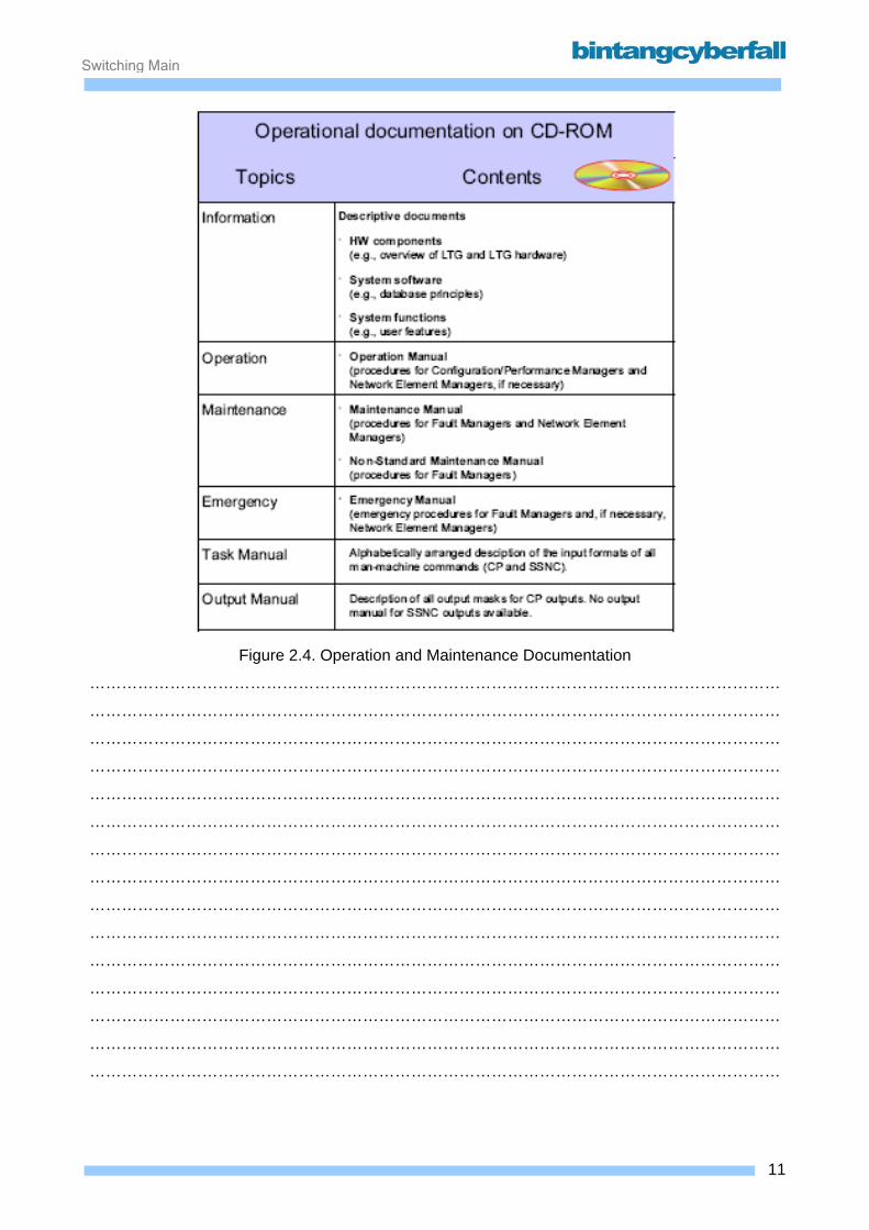
The system documentation is classified according to functions and target groups. It is available to
the network operator's personnel both in paper format as well as electronically (CD-ROM, BCT-
Common, Node Commander/OMC-B).
10BCCN2200 © 2007 Bintang CyberFall
Switching Maintenance
Figure 2.4. Operation and Maintenance Documentation
…………………………………………………………………………………………………………………
…………………………………………………………………………………………………………………
…………………………………………………………………………………………………………………
…………………………………………………………………………………………………………………
…………………………………………………………………………………………………………………
…………………………………………………………………………………………………………………
…………………………………………………………………………………………………………………
…………………………………………………………………………………………………………………
…………………………………………………………………………………………………………………
…………………………………………………………………………………………………………………
…………………………………………………………………………………………………………………
…………………………………………………………………………………………………………………
…………………………………………………………………………………………………………………
…………………………………………………………………………………………………………………
…………………………………………………………………………………………………………………
11BCCN2200 © 2007 Bintang CyberFall
Switching Maintenance
The application used for alarm surveillance at the SC is called AMD (Alarm and Message Display).
List of main features You can use the AMD for the following purposes:
o Displaying of all alarms and messages, which are stored on the Alarm Data Server (ADS)
o Displaying the open alarms and the alarm summary of Network Elements
o Applying filters to the node and alarm list
o Sorting the node and alarm list
o Generating a work order
o Modifying the processing state of an alarm
o Customizing views, filters, columns, sorting, fonts colors and sound
o Supporting online and offline mode
o Displaying a processing state of an alarm
o Exporting of alarms and messages to text files
o Enabling acoustical alarm indications
o Printing of alarm and message lists as well as alarm and message details
o Starting of alarm handling as a display of alarm lists and starting the Interactive Document
Browser for alarm clearance using the corresponding procedure of the maintenance
manual (MMN)
12BCCN2200 © 2007 Bintang CyberFall
Switching Maintenance
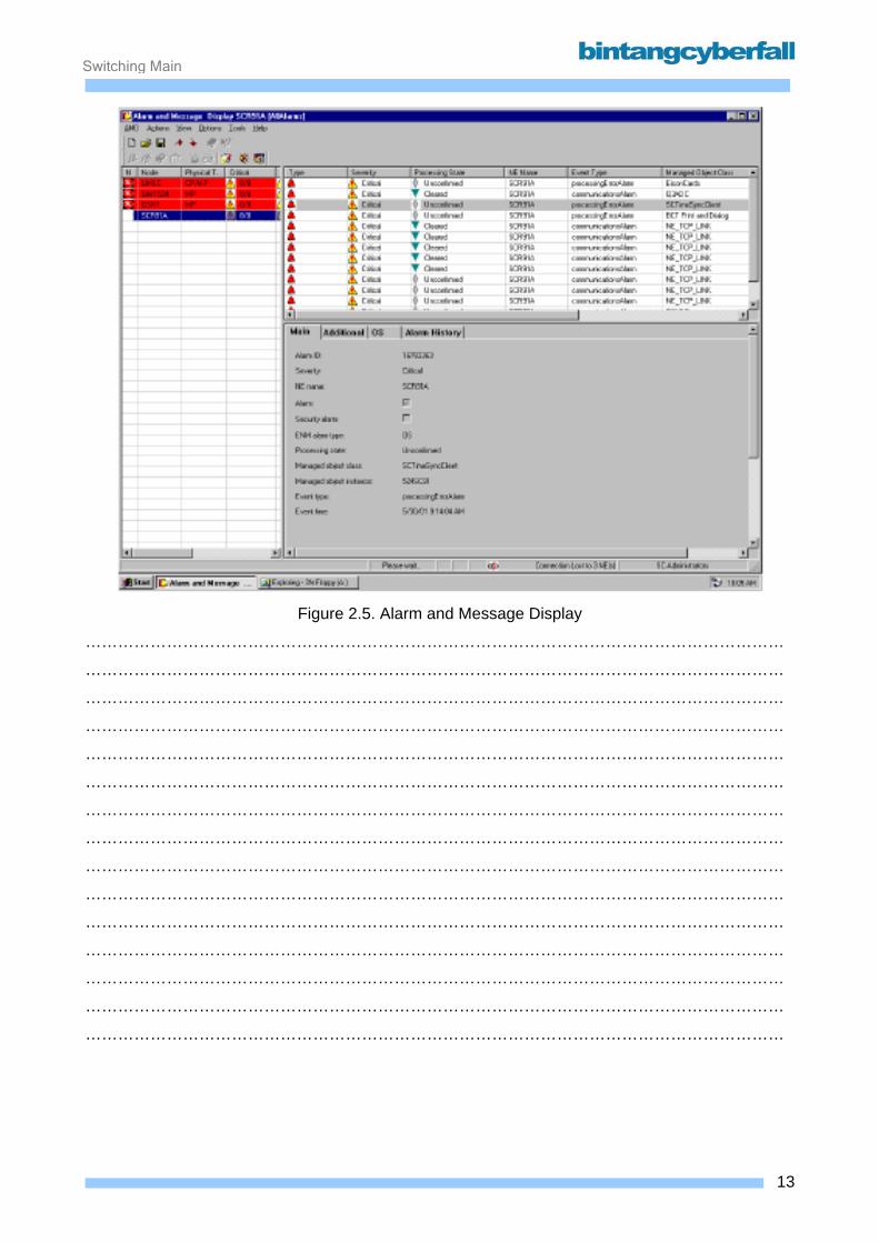
Figure 2.5. Alarm and Message Display
…………………………………………………………………………………………………………………
…………………………………………………………………………………………………………………
…………………………………………………………………………………………………………………
…………………………………………………………………………………………………………………
…………………………………………………………………………………………………………………
…………………………………………………………………………………………………………………
…………………………………………………………………………………………………………………
…………………………………………………………………………………………………………………
…………………………………………………………………………………………………………………
…………………………………………………………………………………………………………………
…………………………………………………………………………………………………………………
…………………………………………………………………………………………………………………
…………………………………………………………………………………………………………………
…………………………………………………………………………………………………………………
…………………………………………………………………………………………………………………
13BCCN2200 © 2007 Bintang CyberFall
Switching Maintenance
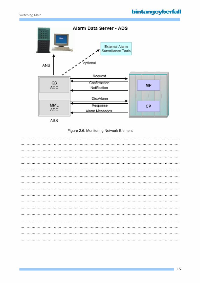
Monitoring network elements There are 4 services responsible for the alarm data handling:
• Q3 ADC - Q3 Alarm Data Collector (for NE's containing an MP)
• MML ADC - MML Alarm Data Collector (for NE's containing a CP)
• ASS - Alarm Store Service
• ANS - Alarm Notification Service
These services together are building the so-called ADS (Alarm Data Server).
The ADC collects the incoming alarms and transfers them to the ASS, which stores them in the
ORACLE database and triggers the ANS to update the view.
The advantage of this concept is the scalability. Each process could run on a different SC and
could be installed in a redundant configuration, which would guarantee more performance and
reliability.
14BCCN2200 © 2007 Bintang CyberFall
Switching Maintenance
Figure 2.6. Monitoring Network Element
…………………………………………………………………………………………………………………
…………………………………………………………………………………………………………………
…………………………………………………………………………………………………………………
…………………………………………………………………………………………………………………
…………………………………………………………………………………………………………………
…………………………………………………………………………………………………………………
…………………………………………………………………………………………………………………
…………………………………………………………………………………………………………………
…………………………………………………………………………………………………………………
…………………………………………………………………………………………………………………
…………………………………………………………………………………………………………………
…………………………………………………………………………………………………………………
…………………………………………………………………………………………………………………
…………………………………………………………………………………………………………………
…………………………………………………………………………………………………………………
…………………………………………………………………………………………………………………
…………………………………………………………………………………………………………………
15BCCN2200 © 2007 Bintang CyberFall
Switching Maintenance
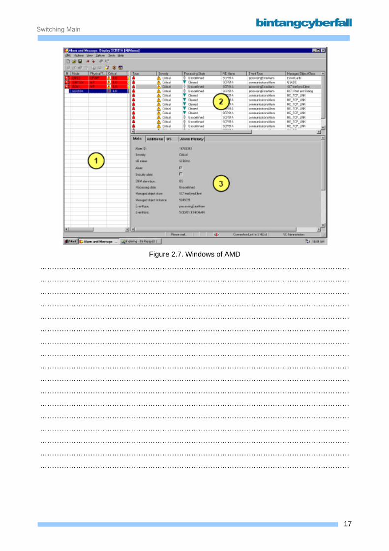
The different window parts of the AMD After the selection of the user group and the individual alarm view you will see the
window in below figure.
The AMD consists of 3 window parts:
1. Node Status window ( left window )
2. Alarm List window ( upper right window )
3. Alarm Details window ( lower right window )
Secondary Windows If you double click on a specific network element, a secondary window comes up which contains
the alarm list window and the alarm details window of this specific network element.
If you do a double click on a specific alarm, a secondary window comes up which contains the
alarm details window of this specific alarm.
You can open as many secondary windows as possible. If you close the main window, all
secondary windows are automatically closed.
The secondary windows contain the same menus and toolbars as the main window.
16BCCN2200 © 2007 Bintang CyberFall
Switching Maintenance
Figure 2.7. Windows of AMD
…………………………………………………………………………………………………………………
…………………………………………………………………………………………………………………
…………………………………………………………………………………………………………………
…………………………………………………………………………………………………………………
…………………………………………………………………………………………………………………
…………………………………………………………………………………………………………………
…………………………………………………………………………………………………………………
…………………………………………………………………………………………………………………
…………………………………………………………………………………………………………………
…………………………………………………………………………………………………………………
…………………………………………………………………………………………………………………
…………………………………………………………………………………………………………………
…………………………………………………………………………………………………………………
…………………………………………………………………………………………………………………
…………………………………………………………………………………………………………………
…………………………………………………………………………………………………………………
…………………………………………………………………………………………………………………
17BCCN2200 © 2007 Bintang CyberFall
Switching Maintenance
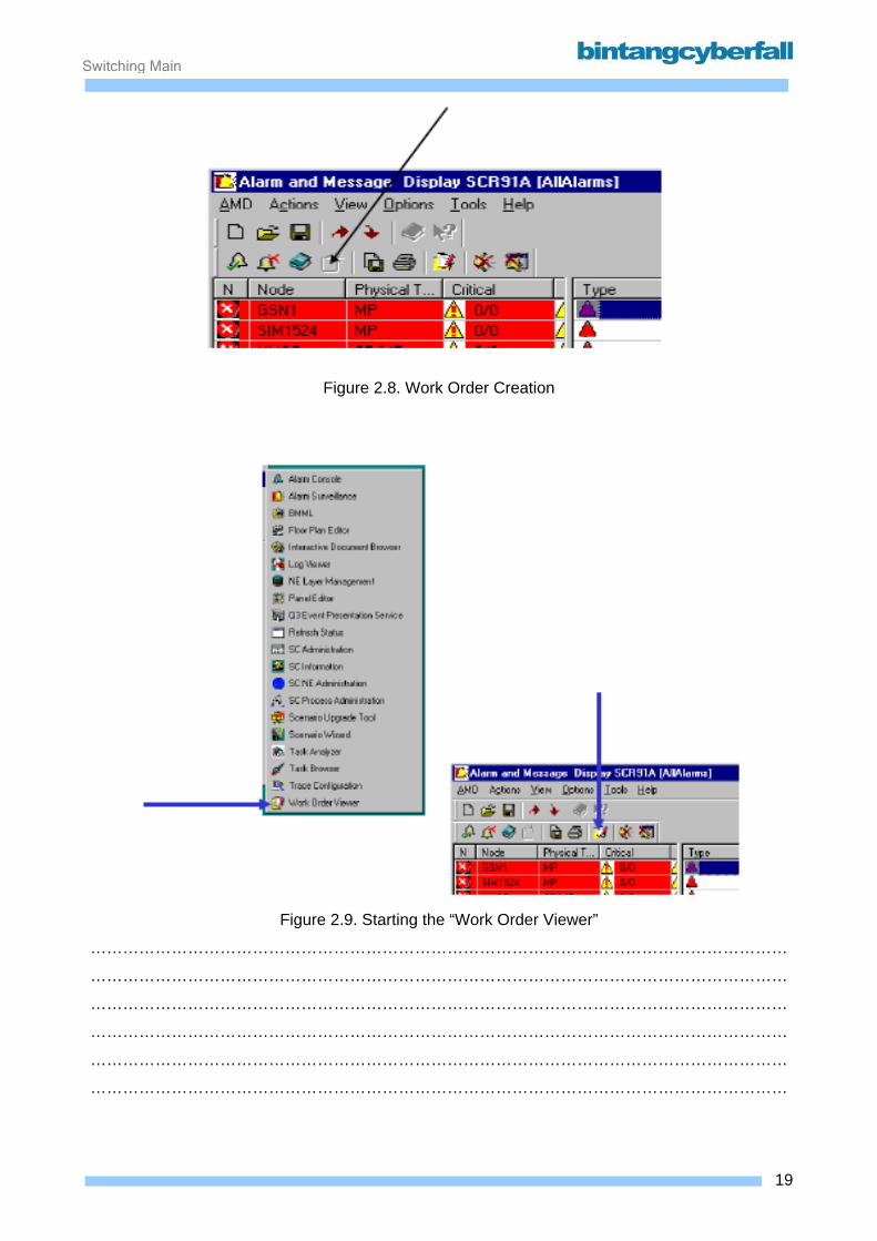
Work order viewer Sometimes it is not possible for an operator to clear a specific alarm directly. (e.g. because a
module has to be replaced and the NE is located at a different place.)
In this case the operator has to inform somebody else to execute the necessary actions. This
information is given by a so-called work order.
A work order is a document containing the information necessary for the repair staff to start fault
clearance at the network element location.
To create a work order, select one or more alarms and click on the Create Work Order Icon of the
Alarm Message Display.
To view, edit and process work orders created for one or more alarms within the AMD application
the, SC application Work Order Viewer is used.
The main features of Work Order Viewer:
• Opening an existing work order document
• Printing a work order document
• Adding remarks to a work order
• Sending a work order document via electronic mail
Starting the Work Order Viewer Work Order Viewer can either be started from the AMD application or separately to edit already
existing work orders.
After starting the Work Order Viewer via the Windows NT Start button you have to open an already
existing work order document.
By starting the Work Order Viewer from the AMD application a work order is created for the
selected alarms and opened in the Work Order Viewer already.
18BCCN2200 © 2007 Bintang CyberFall
Switching Maintenance
Figure 2.8. Work Order Creation
Figure 2.9. Starting the “Work Order Viewer”
…………………………………………………………………………………………………………………
…………………………………………………………………………………………………………………
…………………………………………………………………………………………………………………
…………………………………………………………………………………………………………………
…………………………………………………………………………………………………………………
…………………………………………………………………………………………………………………
19BCCN2200 © 2007 Bintang CyberFall
Switching Maintenance
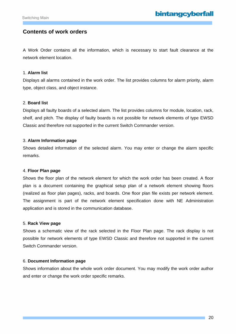
Contents of work orders A Work Order contains all the information, which is necessary to start fault clearance at the
network element location.
1. Alarm list Displays all alarms contained in the work order. The list provides columns for alarm priority, alarm
type, object class, and object instance.
2. Board list Displays all faulty boards of a selected alarm. The list provides columns for module, location, rack,
shelf, and pitch. The display of faulty boards is not possible for network elements of type EWSD
Classic and therefore not supported in the current Switch Commander version.
3. Alarm Information page Shows detailed information of the selected alarm. You may enter or change the alarm specific
remarks.
4. Floor Plan page Shows the floor plan of the network element for which the work order has been created. A floor
plan is a document containing the graphical setup plan of a network element showing floors
(realized as floor plan pages), racks, and boards. One floor plan file exists per network element.
The assignment is part of the network element specification done with NE Administration
application and is stored in the communication database.
5. Rack View page Shows a schematic view of the rack selected in the Floor Plan page. The rack display is not
possible for network elements of type EWSD Classic and therefore not supported in the current
Switch Commander version.
6. Document Information page Shows information about the whole work order document. You may modify the work order author
and enter or change the work order specific remarks.
20BCCN2200 © 2007 Bintang CyberFall
Switching Maintenance
Figure 2.10. Contents of the Work Orders
…………………………………………………………………………………………………………………
…………………………………………………………………………………………………………………
…………………………………………………………………………………………………………………
…………………………………………………………………………………………………………………
…………………………………………………………………………………………………………………
…………………………………………………………………………………………………………………
…………………………………………………………………………………………………………………
…………………………………………………………………………………………………………………
…………………………………………………………………………………………………………………
…………………………………………………………………………………………………………………
…………………………………………………………………………………………………………………
…………………………………………………………………………………………………………………
…………………………………………………………………………………………………………………
…………………………………………………………………………………………………………………
…………………………………………………………………………………………………………………
…………………………………………………………………………………………………………………
…………………………………………………………………………………………………………………
…………………………………………………………………………………………………………………
…………………………………………………………………………………………………………………
21BCCN2200 © 2007 Bintang CyberFall
Switching Maintenance
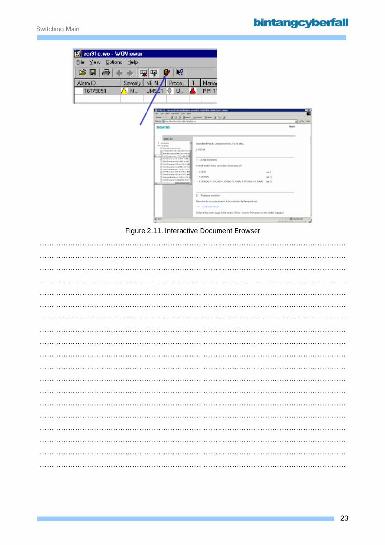
Interactive document browser for alarm clearance You can use the Work Order Viewer – as the Alarm Panel application – to show the detailed alarm
information and start the Interactive Document Browser for displaying the procedure for alarm
clearance in the maintenance manual.
22BCCN2200 © 2007 Bintang CyberFall
Switching Maintenance
Figure 2.11. Interactive Document Browser
…………………………………………………………………………………………………………………
…………………………………………………………………………………………………………………
…………………………………………………………………………………………………………………
…………………………………………………………………………………………………………………
…………………………………………………………………………………………………………………
…………………………………………………………………………………………………………………
…………………………………………………………………………………………………………………
…………………………………………………………………………………………………………………
…………………………………………………………………………………………………………………
…………………………………………………………………………………………………………………
…………………………………………………………………………………………………………………
…………………………………………………………………………………………………………………
…………………………………………………………………………………………………………………
…………………………………………………………………………………………………………………
…………………………………………………………………………………………………………………
…………………………………………………………………………………………………………………
…………………………………………………………………………………………………………………
…………………………………………………………………………………………………………………
…………………………………………………………………………………………………………………
23BCCN2200 © 2007 Bintang CyberFall
Switching Maintenance
Editing a work order
Although Work Order Viewer basically is used to display work orders, you can add or change the
following information before saving or sending the work order as electronic mail:
• Name of the work order author,
• Work order specific, and
• Alarm specific remarks.
Work Orders are stored at a shared directory at the file server.
It can be found e.g. under:
1. Network Neighborhood
2. Fileserver (WIN NT machine name of the Fileserver)
3. SC Base
4. Alarm Surveillance
5. WorkOrderDir
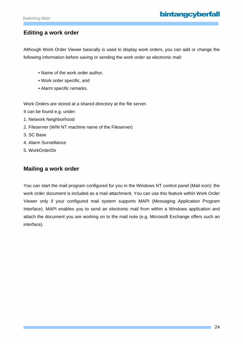
Mailing a work order You can start the mail program configured for you in the Windows NT control panel (Mail icon): the
work order document is included as a mail attachment. You can use this feature within Work Order
Viewer only if your configured mail system supports MAPI (Messaging Application Program
Interface). MAPI enables you to send an electronic mail from within a Windows application and
attach the document you are working on to the mail note (e.g. Microsoft Exchange offers such an
interface).
24BCCN2200 © 2007 Bintang CyberFall
Switching Maintenance
Figure 2.12. Sending Work Order Using Email
…………………………………………………………………………………………………………………
…………………………………………………………………………………………………………………
…………………………………………………………………………………………………………………
…………………………………………………………………………………………………………………
…………………………………………………………………………………………………………………
…………………………………………………………………………………………………………………
…………………………………………………………………………………………………………………
…………………………………………………………………………………………………………………
…………………………………………………………………………………………………………………
…………………………………………………………………………………………………………………
…………………………………………………………………………………………………………………
…………………………………………………………………………………………………………………
…………………………………………………………………………………………………………………
…………………………………………………………………………………………………………………
…………………………………………………………………………………………………………………
…………………………………………………………………………………………………………………
…………………………………………………………………………………………………………………
…………………………………………………………………………………………………………………
…………………………………………………………………………………………………………………
25BCCN2200 © 2007 Bintang CyberFall
Switching Maintenance
2.1.2. Alarm Clearance
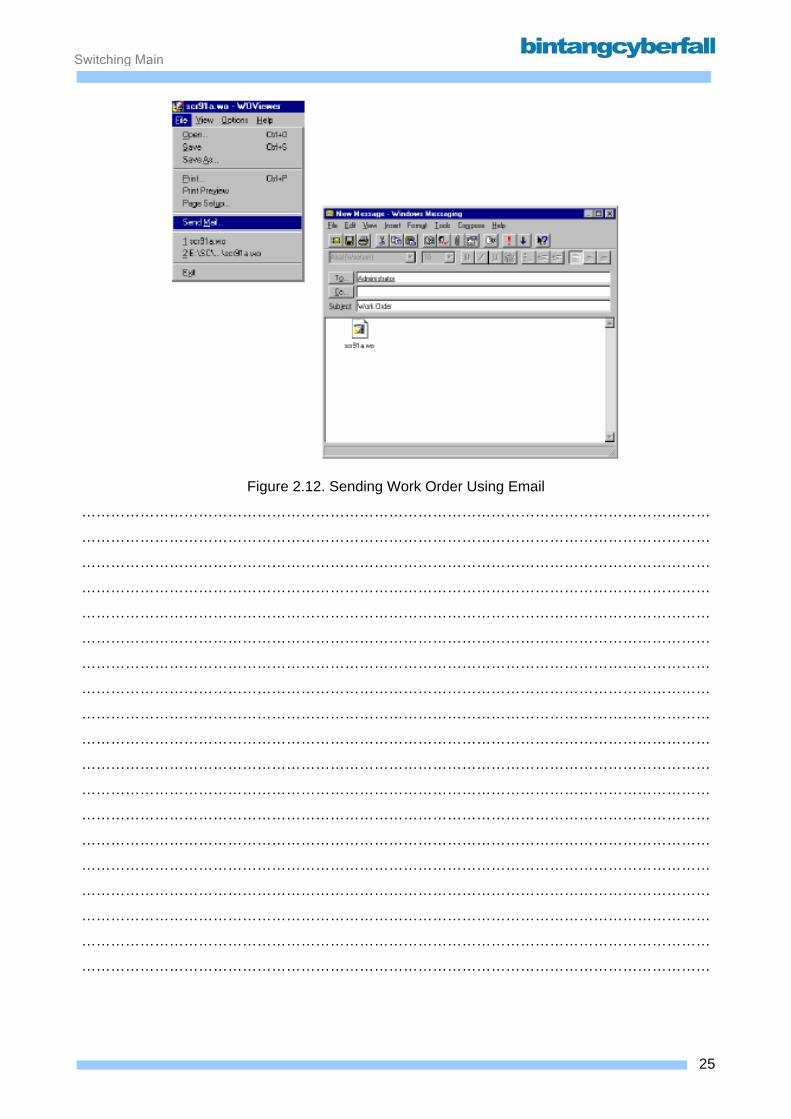
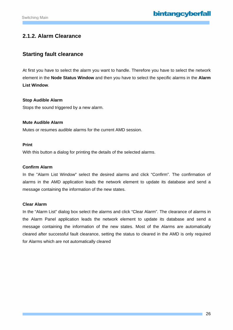
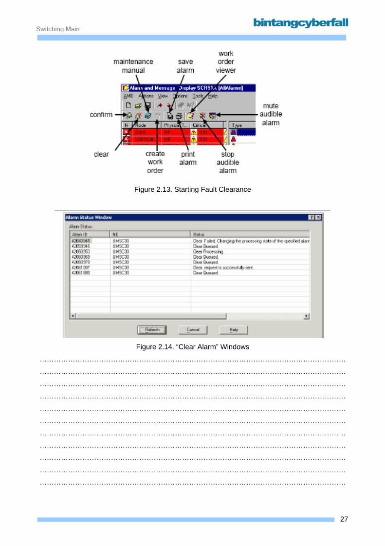
Starting fault clearance At first you have to select the alarm you want to handle. Therefore you have to select the network
element in the Node Status Window and then you have to select the specific alarms in the Alarm List Window.
Stop Audible Alarm Stops the sound triggered by a new alarm.
Mute Audible Alarm Mutes or resumes audible alarms for the current AMD session.
Print With this button a dialog for printing the details of the selected alarms.
Confirm Alarm In the "Alarm List Window" select the desired alarms and click “Confirm”. The confirmation of
alarms in the AMD application leads the network element to update its database and send a
message containing the information of the new states.
Clear Alarm In the “Alarm List” dialog box select the alarms and click “Clear Alarm”. The clearance of alarms in
the Alarm Panel application leads the network element to update its database and send a
message containing the information of the new states. Most of the Alarms are automatically
cleared after successful fault clearance, setting the status to cleared in the AMD is only required
for Alarms which are not automatically cleared
26BCCN2200 © 2007 Bintang CyberFall
Switching Maintenance
Figure 2.13. Starting Fault Clearance
Figure 2.14. “Clear Alarm” Windows
…………………………………………………………………………………………………………………
…………………………………………………………………………………………………………………
…………………………………………………………………………………………………………………
…………………………………………………………………………………………………………………
…………………………………………………………………………………………………………………
…………………………………………………………………………………………………………………
…………………………………………………………………………………………………………………
…………………………………………………………………………………………………………………
…………………………………………………………………………………………………………………
…………………………………………………………………………………………………………………
…………………………………………………………………………………………………………………
27BCCN2200 © 2007 Bintang CyberFall
Switching Maintenance
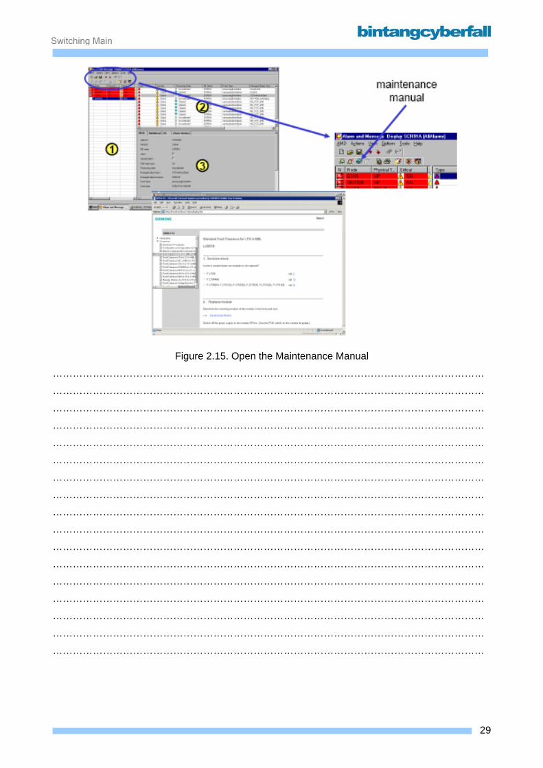
Maintenance Manual The alarm clearance with the help of the Interactive Document Browser is only possible for alarms,
which provide the information about the corresponding maintenance manual (MMN) procedure.
The Alarm Status of some CP Alarm Objects like "RECOV" or "SYOP" must be changed manually
via the Workbench.
To change the status to "in process" (confirmed):
SETALSTAT:MSGNO=<msg no.>,ALSTAT=IP;
To change the status to "cleared"
SETALSTAT:MSGNO=<msg no.>,ALSTAT=C;
28BCCN2200 © 2007 Bintang CyberFall
Switching Maintenance
Figure 2.15. Open the Maintenance Manual
…………………………………………………………………………………………………………………
…………………………………………………………………………………………………………………
…………………………………………………………………………………………………………………
…………………………………………………………………………………………………………………
…………………………………………………………………………………………………………………
…………………………………………………………………………………………………………………
…………………………………………………………………………………………………………………
…………………………………………………………………………………………………………………
…………………………………………………………………………………………………………………
…………………………………………………………………………………………………………………
…………………………………………………………………………………………………………………
…………………………………………………………………………………………………………………
…………………………………………………………………………………………………………………
…………………………………………………………………………………………………………………
…………………………………………………………………………………………………………………
…………………………………………………………………………………………………………………
…………………………………………………………………………………………………………………
29BCCN2200 © 2007 Bintang CyberFall
Switching Maintenance
2.1.3. Escalation
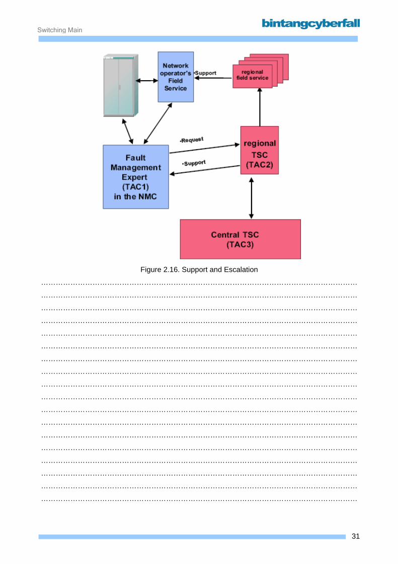
Technical assistance centers TAC2 & TAC3 for network operator support are positioned in the
country-/project-specific and central technical service centers (TSC).
Generally, the fault management expert (also known as TAC1) is the network operator's partner of
the TAC.
The TAC2 personnel in the country-/project-specific TSC analyze queries/fault reports submitted
by the network operator and either respond themselves or transfer them to the TAC3 personnel in
the central TSC in Munich.
This after-sales service concept is named Performance Plus.
Performance Plus includes the following feature packages:
o Emergency Service It is provided a 24-hour hotline service to deal with serious faults in EWSD
systems. This refers principally to clearance of faults classified as so-called EWSD
emergency situations.
o Fault Report Processing All faults are reported by the network operator to the TSC.
If faults are independently cleared by the network operator fault management/field service,
the corresponding fault reports are used by the TSC for statistical purposes only.
In cases in which the network operator can't resolve faults (for example, software errors
requiring correction by patch), the network operator personnel is supported by the TSC .
o Field Service The regional field service provides support to the network operator's field service personnel
(network element manager, network element assistant) for onsite maintenance and fault
clearance if necessary.
o Repair and Replacement Service The network operator dispatches faulty hardware components to the TSC. There they are
repaired/replaced and afterwards returned.
Independent of these actions, network operators generally have their own pools of
replacement modules for fault clearance.
o Software/hardware update The TSC supplies customers with all necessary, up-to-date EWSD components (for
example, EPROM with updated firmware).
30BCCN2200 © 2007 Bintang CyberFall
Switching Maintenance
Figure 2.16. Support and Escalation
…………………………………………………………………………………………………………………
…………………………………………………………………………………………………………………
…………………………………………………………………………………………………………………
…………………………………………………………………………………………………………………
…………………………………………………………………………………………………………………
…………………………………………………………………………………………………………………
…………………………………………………………………………………………………………………
…………………………………………………………………………………………………………………
…………………………………………………………………………………………………………………
…………………………………………………………………………………………………………………
…………………………………………………………………………………………………………………
…………………………………………………………………………………………………………………
…………………………………………………………………………………………………………………
…………………………………………………………………………………………………………………
…………………………………………………………………………………………………………………
…………………………………………………………………………………………………………………
…………………………………………………………………………………………………………………
…………………………………………………………………………………………………………………
31BCCN2200 © 2007 Bintang CyberFall
Switching Maintenance
2.2. Language and Communication
32BCCN2200 © 2007 Bintang CyberFall
Switching Maintenance
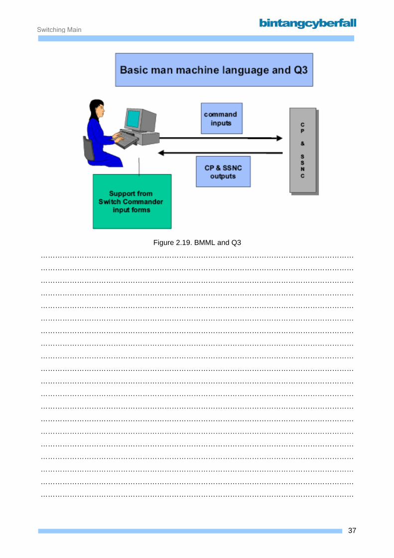
The command language used by the CP is called man-machine-language MML. It can be used for
the CP only and may be entered via switch commander or BCT-boot.
The switch commander also supports Q3 scripts. This is used to communicate with the SSNC.
Communication to the CP is based on MML commands, and communication to the SSNC is based
on Q3 commands. The BCT-Boot software does not support Q3.
o MML-commands => CP
o Q3 tasks => SSNC
Forms organized in a menu tree can be provided in the Switch Commander for the input of MML
and Q3 commands. It allows significantly simplified system command operations due to the menu
and form method used. Also, it allows the use of Q3 scripts for communication with the SSNC.
33BCCN2200 © 2007 Bintang CyberFall
Switching Maintenance
2.2.1. Communication Interfaces
The Craft Terminal is used for operation and maintenance of the exchanges. It replaces the old
text based local OMT with a modern graphical user interface.
Depending on the hardware and software the following terms are used:
BCT Basic Craft Terminal. Only the BCT/BOOT software is installed. Connection to the exchange via
V.24 interface.
CT Craft Terminal. Switch Commander software or/and BCT/COMMON software is installed.
Connection to the exchange via TCP/IP or X.25 interface.
(The X.25 interface can only be used for BCT/COMMON) The BCT/BOOT software can be
simultaneously installed on the same personal computer, again using V.24 interface for
connection.
BCT/BOOT Software for BCT. Only BMML commands can be entered.
BCT/COMMON Software for CT. The BMML and EMML modes are available.
Switch Commander Software for CT. Only the quick select mask input mode is available.
Connection to the exchange Two figures below show the connection methods of the BCT or CT hardware to the coordination
processor and SSNC of the exchange. The BCT/BOOT software is only used for direct
connections to the CP. BCT/COMMON software can be connected to the CP via X.25 software or
through the SSNC via TCP/IP. Switch Commander can be simultaneously connected to the CP
and SSNC of different exchanges via an TCP/IP network.
If a TCP/IP or X.25 connections are used, it is not possible to transfer or execute anything if these
links are not active, e.g. while the exchange is in installation or split operation mode! In this case
only the BCT/BOOT software can be used.
34BCCN2200 © 2007 Bintang CyberFall

Switching Maintenance
Figure 2.17. V.24 Connection of the BCT to Exchange
Figure 2.18. TCP/IP Connection of the CT to Exchange
35BCCN2200 © 2007 Bintang CyberFall
Switching Maintenance
2.2.2. Commands and Syntaxes
Basic MML Basic man machine language (BMML), the structure of which is based on an ITU
recommendation, was created for communication between the operators and the coordination
processor CP.
BMML contains all the rules to carry out standardized information exchange between the user
programs and the operating personnel. BMML is divided into 2 elements:
o BMML commands All possible entries of the operating personnel (Q3 and MML) are documented in
the task manual TML.
o Outputs of the CP All CP output masks are documented in the output manual OML.
36BCCN2200 © 2007 Bintang CyberFall
Switching Maintenance
Figure 2.19. BMML and Q3
…………………………………………………………………………………………………………………
…………………………………………………………………………………………………………………
…………………………………………………………………………………………………………………
…………………………………………………………………………………………………………………
…………………………………………………………………………………………………………………
…………………………………………………………………………………………………………………
…………………………………………………………………………………………………………………
…………………………………………………………………………………………………………………
…………………………………………………………………………………………………………………
…………………………………………………………………………………………………………………
…………………………………………………………………………………………………………………
…………………………………………………………………………………………………………………
…………………………………………………………………………………………………………………
…………………………………………………………………………………………………………………
…………………………………………………………………………………………………………………
…………………………………………………………………………………………………………………
…………………………………………………………………………………………………………………
…………………………………………………………………………………………………………………
…………………………………………………………………………………………………………………
…………………………………………………………………………………………………………………
37BCCN2200 © 2007 Bintang CyberFall

Switching Maintenance
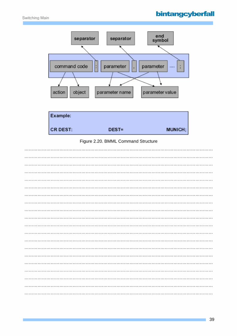
BMML command structure A BMML command contains the following components:
o The command code contains the action and the object.
The action indicates how the following object is handled, for example “display”,
“creation”, “configuration” etc.
The object indicates for which system unit or which call handling data object the
action is to be carried out. E.g. “LTG”, “SN”, “ROUTE”, “SUBscriber” etc.
o A colon, “:”, serves as a separation sign between the command code and the
following parameters.
o The parameters are not only identified by a certain position, but by their codes.
They can therefore be located at any position and are composed of the parameter name
and the parameter value.
o A comma, ”,”, serves as a separation sign between the individual parameters.
o The BMML command status usually ends with a semicolon ”;”.
38BCCN2200 © 2007 Bintang CyberFall
Switching Maintenance
Figure 2.20. BMML Command Structure
…………………………………………………………………………………………………………………
…………………………………………………………………………………………………………………
…………………………………………………………………………………………………………………
…………………………………………………………………………………………………………………
…………………………………………………………………………………………………………………
…………………………………………………………………………………………………………………
…………………………………………………………………………………………………………………
…………………………………………………………………………………………………………………
…………………………………………………………………………………………………………………
…………………………………………………………………………………………………………………
…………………………………………………………………………………………………………………
…………………………………………………………………………………………………………………
…………………………………………………………………………………………………………………
…………………………………………………………………………………………………………………
…………………………………………………………………………………………………………………
…………………………………………………………………………………………………………………
…………………………………………………………………………………………………………………
…………………………………………………………………………………………………………………
…………………………………………………………………………………………………………………
…………………………………………………………………………………………………………………
39BCCN2200 © 2007 Bintang CyberFall
Switching Maintenance
Typical actions of a BMML command The most commonly used MML commands are for creating, deleting, changing and displaying call
processing database objects, and for the configuration, diagnosis and display of the configuration
status of hardware units.
40BCCN2200 © 2007 Bintang CyberFall

Switching Maintenance
Figure 2.21. BMML Command Actions
…………………………………………………………………………………………………………………
…………………………………………………………………………………………………………………
…………………………………………………………………………………………………………………
…………………………………………………………………………………………………………………
…………………………………………………………………………………………………………………
…………………………………………………………………………………………………………………
…………………………………………………………………………………………………………………
…………………………………………………………………………………………………………………
…………………………………………………………………………………………………………………
…………………………………………………………………………………………………………………
…………………………………………………………………………………………………………………
…………………………………………………………………………………………………………………
41BCCN2200 © 2007 Bintang CyberFall
Switching Maintenance
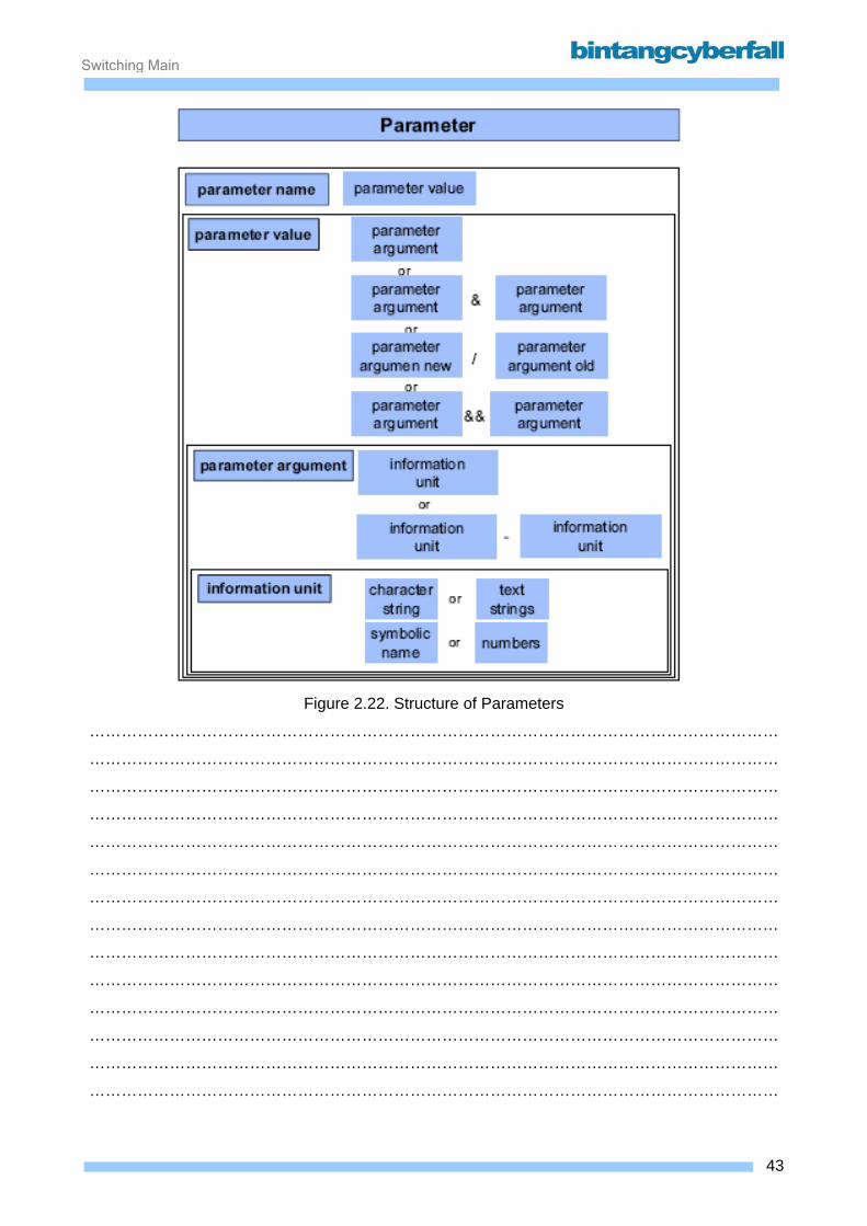
Structure of the parameters of a BMML command As already mentioned, a parameter is divided into a parameter name and a parameter value.
A parameter value consists of one or more parameter arguments.
A parameter argument consists of one or more information units.
The following elements can be used as information units:
o Character string
e.g. for the parameter TGNO (name of a trunk line)
TGNO = JKT1
o Text sequence
e.g. for the parameter PRO (name of a processor)
PRO = “BCT-COMMON“
o Symbolic name
e.g. for the parameter SERV (services of an ISDN subscriber)
SERV = TELKOM2
o Numbers
e.g. for the parameter DN (directory number of a subscriber)
DN = 33301
42BCCN2200 © 2007 Bintang CyberFall
Switching Maintenance
Figure 2.22. Structure of Parameters
…………………………………………………………………………………………………………………
…………………………………………………………………………………………………………………
…………………………………………………………………………………………………………………
…………………………………………………………………………………………………………………
…………………………………………………………………………………………………………………
…………………………………………………………………………………………………………………
…………………………………………………………………………………………………………………
…………………………………………………………………………………………………………………
…………………………………………………………………………………………………………………
…………………………………………………………………………………………………………………
…………………………………………………………………………………………………………………
…………………………………………………………………………………………………………………
…………………………………………………………………………………………………………………
…………………………………………………………………………………………………………………
43BCCN2200 © 2007 Bintang CyberFall

Switching Maintenance
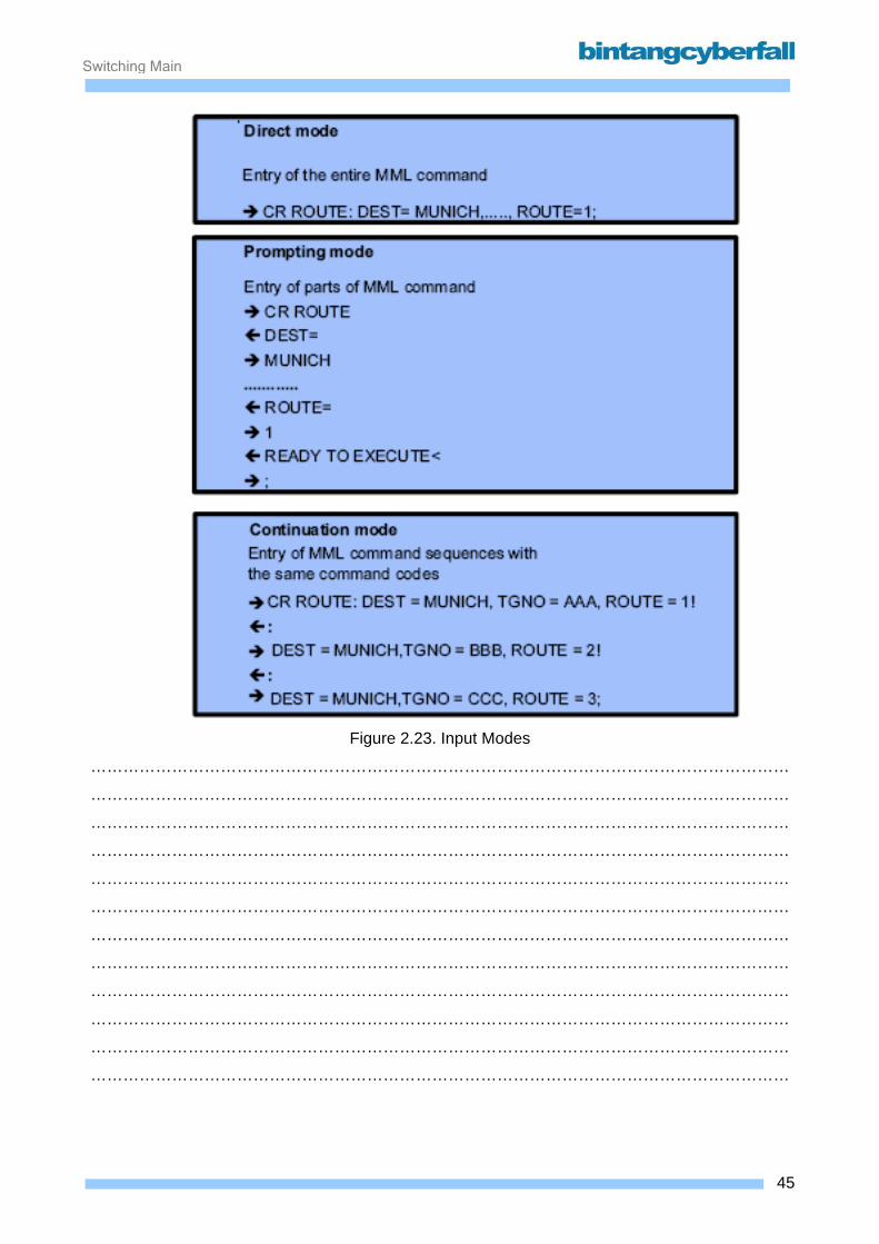
Entry modes for BMML commands Various modes can be used for the input of basic MML commands:
Direct mode The basic MML command is entered and sent in its entirety including the parameter and
the end sign ”;”.
Prompting mode The basic MML command is only partially entered and sent. The entry can be sent after the
command code without “:” and after every parameter without ”,”. The system then switches
to an interactive mode and queries all possible parameters and finally the end sign “;”
individually. This interactive mode can be quit at any time by the user by entering the end
sign ”;”. Parameters which are not queried at this point can also be entered. To do so,
instead of or after entry of the queried parameter, enter the separator ”,” followed by a
parameter name and a parameter value.
Continuation mode Instead of ending a basic MML command with ”;”, it is also possible to fall into the so-called
continuation mode by entering an exclamation point “!”. This is only possible with a
sequence of basic MML commands with the same command codes.
After entering a command in continuation mode, the system expects the next command
beginning with the first parameter name without command code.
However, the last command of the sequence (i.e. before a command code which deviates
from the sequence is to be used) must be ended with ”;”.
Continuation mode is used in command files to improve speed because it is not necessary
to restart the user program when entering commands from the 2nd command to the last
command of a sequence. However, it is also used in MML commands which only fulfill
partial tasks after entry of the particular command and which do not complete the entire
task until after entry of the terminating ”;”.
44BCCN2200 © 2007 Bintang CyberFall
Switching Maintenance
Figure 2.23. Input Modes
…………………………………………………………………………………………………………………
…………………………………………………………………………………………………………………
…………………………………………………………………………………………………………………
…………………………………………………………………………………………………………………
…………………………………………………………………………………………………………………
…………………………………………………………………………………………………………………
…………………………………………………………………………………………………………………
…………………………………………………………………………………………………………………
…………………………………………………………………………………………………………………
…………………………………………………………………………………………………………………
…………………………………………………………………………………………………………………
…………………………………………………………………………………………………………………
45BCCN2200 © 2007 Bintang CyberFall

Switching Maintenance
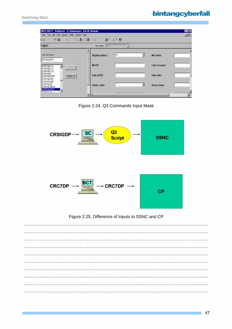
Q3 commands Unlike MML commands, are Q3 commands based on an ITU-T defined interface and are therefore
a standard language. Q3 commands are only used for communication with the SSNC. These
commands (or tasks) are translated to Q3 scripts by the switch commander software. These Q3
scripts are then sent to the SSNC, which provides the output.
The following differences can be identified between MML and Q3 commands.
Q3 is an ITU-T standard language, whereas MML is a specific language.
Q3 commands (or tasks) are translated to Q3 scripts and then sent to the SSNC. MML
commands are sent directly to the CP.
The input of Q3 commands can only be done by means if an input mask and not with an
input line.
Q3 commands do not use abbreviations; all parameters are full written text.
Q3 commands cannot be used in command files.
46BCCN2200 © 2007 Bintang CyberFall
Switching Maintenance
Figure 2.24. Q3 Commands Input Mask
Figure 2.25. Difference of Inputs to SSNC and CP
…………………………………………………………………………………………………………………
…………………………………………………………………………………………………………………
…………………………………………………………………………………………………………………
…………………………………………………………………………………………………………………
…………………………………………………………………………………………………………………
…………………………………………………………………………………………………………………
…………………………………………………………………………………………………………………
…………………………………………………………………………………………………………………
…………………………………………………………………………………………………………………
…………………………………………………………………………………………………………………
47BCCN2200 © 2007 Bintang CyberFall

Switching Maintenance
2.3. Project Specific Documents
48BCCN2200 © 2007 Bintang CyberFall
Switching Maintenance
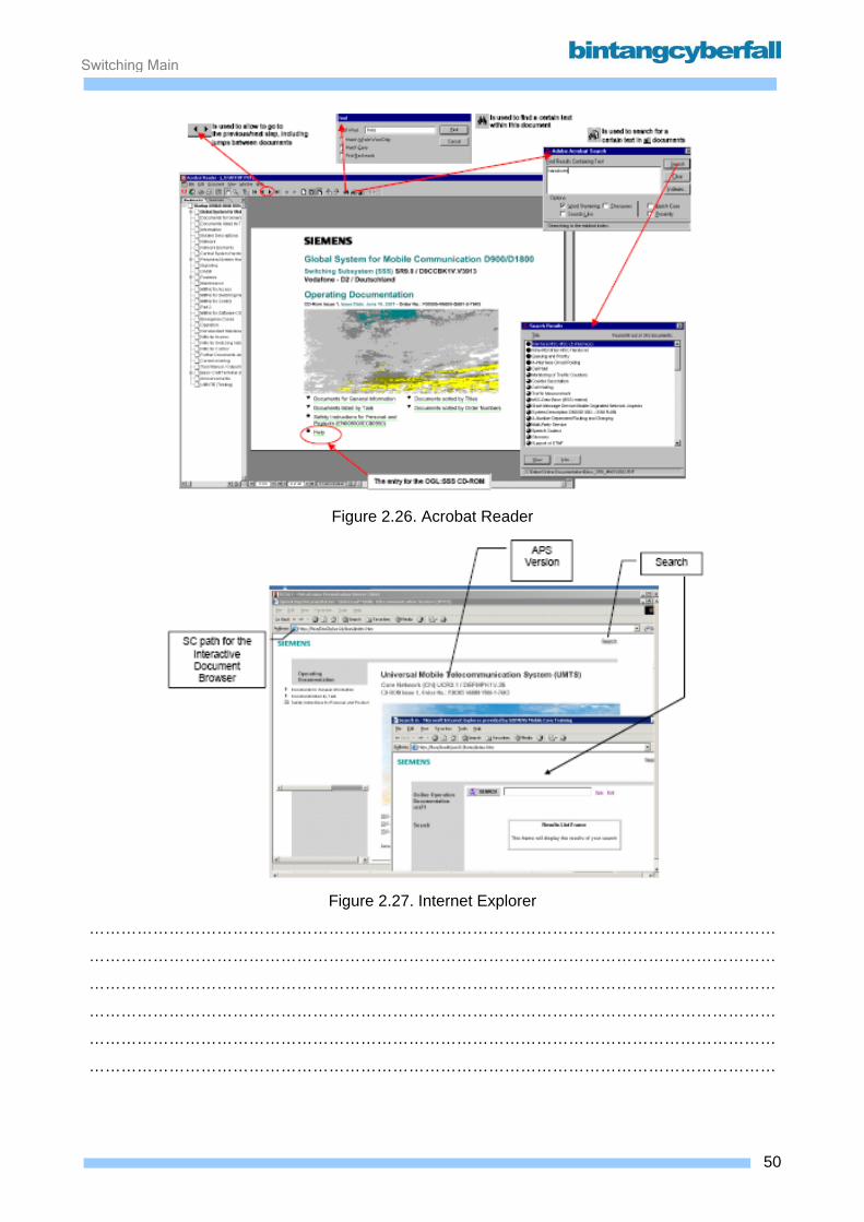
Viewer for online documentation All the documentation required for the operation of a D900/D1800/D1900 network node is
electronically available on CD-ROM. The documentation includes descriptions and manuals
assigned to specific function areas and tasks.
For displaying the different formats of electronic documentation (e.g. CML, MMN, OML,..) the
Interactive Document Browser (Application on SC) can start the Internet Explorer based on HTML
Documents and the Acrobat Reader for documents in Portable Document Format (PDF). Also the
Viewers can be started manually as shown in the next chapters.
49BCCN2200 © 2007 Bintang CyberFall
Switching Maintenance
Figure 2.26. Acrobat Reader
Figure 2.27. Internet Explorer
…………………………………………………………………………………………………………………
…………………………………………………………………………………………………………………
…………………………………………………………………………………………………………………
…………………………………………………………………………………………………………………
…………………………………………………………………………………………………………………
…………………………………………………………………………………………………………………
50BCCN2200 © 2007 Bintang CyberFall
Switching Maintenance
2.3.1. Tools and Documents
Task Manual (TML) The Task Manual is a project-specific documentation package, which contains all tasks needed to
operate the system with the corresponding parameters.
The TML consists of the following components, the reason for the different names are the different
kinds of viewers:
• Introduction section
This contains an explanation on how to the use of the CML. An essential component is the
description of the depiction form of the command syntax in the CMD section.
• TASK or CMD section
The most important section of this manual.
• Cross reference list (called TAB at Acrobat Reader)
The TAB or cross-reference section contains a correlation table of all output masks
belonging to the corresponding MML command. Using these mask numbers (each output
mask has an unique number), one can branch to the “output manual” (OML), where all
layouts of the masks are described in detail.
51BCCN2200 © 2007 Bintang CyberFall

Switching Maintenance
Figure 2.28. TML with Acrobat Reader
…………………………………………………………………………………………………………………
…………………………………………………………………………………………………………………
…………………………………………………………………………………………………………………
…………………………………………………………………………………………………………………
…………………………………………………………………………………………………………………
…………………………………………………………………………………………………………………
…………………………………………………………………………………………………………………
…………………………………………………………………………………………………………………
…………………………………………………………………………………………………………………
…………………………………………………………………………………………………………………
…………………………………………………………………………………………………………………
…………………………………………………………………………………………………………………
…………………………………………………………………………………………………………………
…………………………………………………………………………………………………………………
…………………………………………………………………………………………………………………
…………………………………………………………………………………………………………………
…………………………………………………………………………………………………………………
…………………………………………………………………………………………………………………
…………………………………………………………………………………………………………………
…………………………………………………………………………………………………………………
…………………………………………………………………………………………………………………
…………………………………………………………………………………………………………………
…………………………………………………………………………………………………………………
52BCCN2200 © 2007 Bintang CyberFall

Switching Maintenance
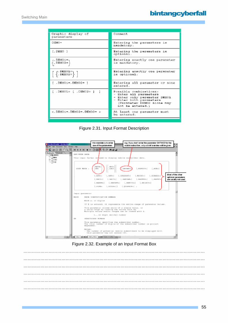
The most frequently used part of the TML is the 'CMD' section with the project specific command
description. It contains all commands sorted alphabetically according to the Object. There one can
branch to all actions which are possible for this object. For every Command Code (Action +
Object), the following information is available (command description):
• general function description of the command
• the input format description of the command (maybe different input formats for one
command e.g. CR MSUB for GSM or GPRS Subscriber)
• description of the individual parameters and values. In case of multiple values the input
format is also described.
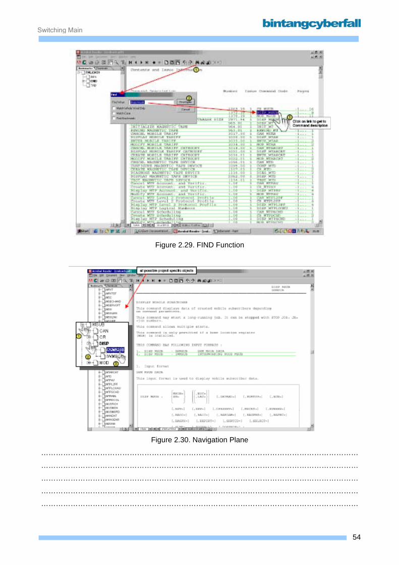
Basically there are two possibilities to find a command description:
1. The quicker variant is the FIND function. The search is done with the entered command
code (action + object). The action and object must be separated with a blank or underscore
(e.g. CONF LTG). Disadvantage: The complete command code must be known.
2. The easier possibility is to use the Navigation Pane (left column). When the desired Object
is found, one can click on the plus sign next to the object to open the branch with the
possible actions for this object. By clicking on one of this actions, the command description
is shown in the main window. Disadvantage: The Object in the Navigation Pane has to be
found manually as there is no search mechanism.
53BCCN2200 © 2007 Bintang CyberFall
Switching Maintenance
Figure 2.29. FIND Function
Figure 2.30. Navigation Plane
…………………………………………………………………………………………………………………
…………………………………………………………………………………………………………………
…………………………………………………………………………………………………………………
…………………………………………………………………………………………………………………
…………………………………………………………………………………………………………………
54BCCN2200 © 2007 Bintang CyberFall
Switching Maintenance
Figure 2.31. Input Format Description
Figure 2.32. Example of an Input Format Box
…………………………………………………………………………………………………………………
…………………………………………………………………………………………………………………
…………………………………………………………………………………………………………………
…………………………………………………………………………………………………………………
…………………………………………………………………………………………………………………
…………………………………………………………………………………………………………………
55BCCN2200 © 2007 Bintang CyberFall

Switching Maintenance
Output Manual (OML) The OML is a project-specific document describing all output layouts. It is available on CD-ROM.
For CP-printouts the mask number in the header of an output is used for entry into the OML.
SSNC (MP) printouts can not be found in the OML.
The OML consists of the following components:
• Contents section (only using Acrobat Reader)
The contents of the OML in the form of all output lists contained in it, including variants and
corrected versions.
• Introduction section
The introduction section corresponds to the one in the CML.
• Mask description section (MSK or Mask)
The OML describes every layout according to lines and columns. I.e. for every information
at a particular line/column position in the output mask, there is a corresponding description
in the OML.
• TAB section
In the TAB (tables) chapter of the OML, one can find the reference from the particular mask
number to the corresponding standard message group. The standard message group is
used if output messages are to be diverted to special output devices, files, etc.
56BCCN2200 © 2007 Bintang CyberFall
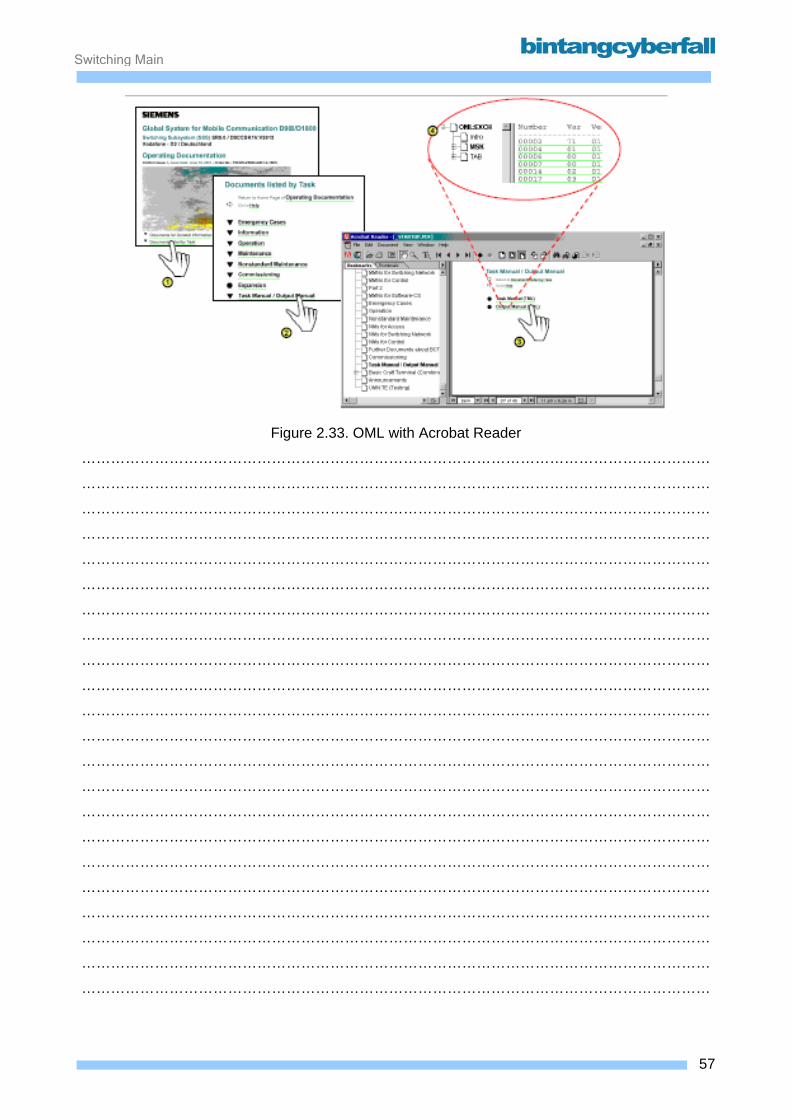
Switching Maintenance
Figure 2.33. OML with Acrobat Reader
…………………………………………………………………………………………………………………
…………………………………………………………………………………………………………………
…………………………………………………………………………………………………………………
…………………………………………………………………………………………………………………
…………………………………………………………………………………………………………………
…………………………………………………………………………………………………………………
…………………………………………………………………………………………………………………
…………………………………………………………………………………………………………………
…………………………………………………………………………………………………………………
…………………………………………………………………………………………………………………
…………………………………………………………………………………………………………………
…………………………………………………………………………………………………………………
…………………………………………………………………………………………………………………
…………………………………………………………………………………………………………………
…………………………………………………………………………………………………………………
…………………………………………………………………………………………………………………
…………………………………………………………………………………………………………………
…………………………………………………………………………………………………………………
…………………………………………………………………………………………………………………
…………………………………………………………………………………………………………………
…………………………………………………………………………………………………………………
…………………………………………………………………………………………………………………
57BCCN2200 © 2007 Bintang CyberFall
Switching Maintenance
OML (mask description) using Acrobat Reader To find the desired mask description for a system output of a Network Element (NE), the Layout or
Message Number is needed.
With the Acrobat Reader, there are two possibilities to find this information:
• The already described ‘FIND’ function can be used to directly enter the number of the
system output.
• The navigation pane on the right. Open the section msk to open the branch with the mask
number ranges. Go through the tree to the matching output number. Use the '+' signs to
open branches.
58BCCN2200 © 2007 Bintang CyberFall
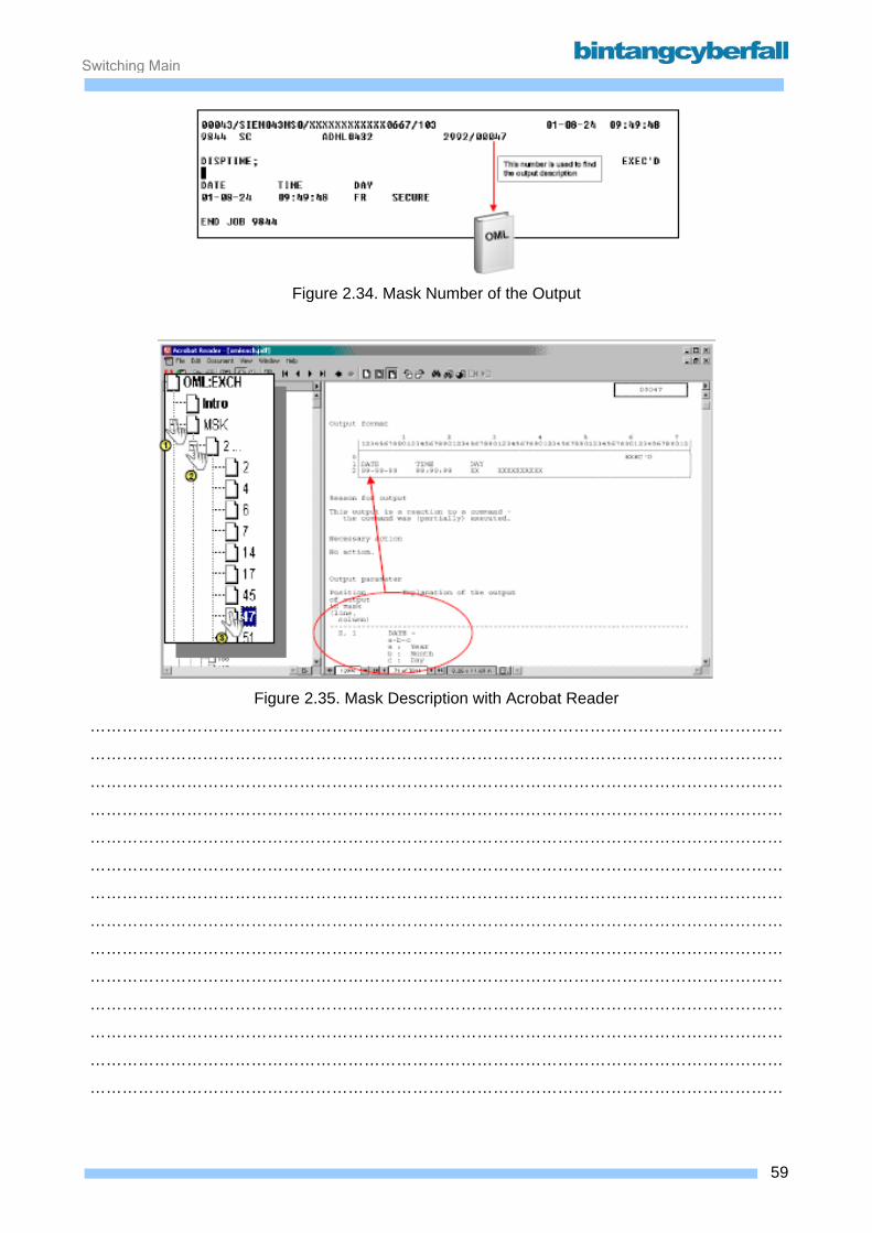
Switching Maintenance
Figure 2.34. Mask Number of the Output
Figure 2.35. Mask Description with Acrobat Reader
…………………………………………………………………………………………………………………
…………………………………………………………………………………………………………………
…………………………………………………………………………………………………………………
…………………………………………………………………………………………………………………
…………………………………………………………………………………………………………………
…………………………………………………………………………………………………………………
…………………………………………………………………………………………………………………
…………………………………………………………………………………………………………………
…………………………………………………………………………………………………………………
…………………………………………………………………………………………………………………
…………………………………………………………………………………………………………………
…………………………………………………………………………………………………………………
…………………………………………………………………………………………………………………
…………………………………………………………………………………………………………………
59BCCN2200 © 2007 Bintang CyberFall
Switching Maintenance
Maintenance Manual (MMN) Standard HW maintenance is initiated on the basis of an alarm on the AMD / Alarm Surveillance or
other alarm displays in the OMC/NMC. The alarm displays branch to the maintenance manuals
which include procedures to control the fault clearance.
The guidelines for electrostatic sensitive devices have to be followed when executing HW
maintenance procedures. Furthermore the Exchange Configuration Documentation has to be used
to localize the faulty module in the exchange room.
60BCCN2200 © 2007 Bintang CyberFall
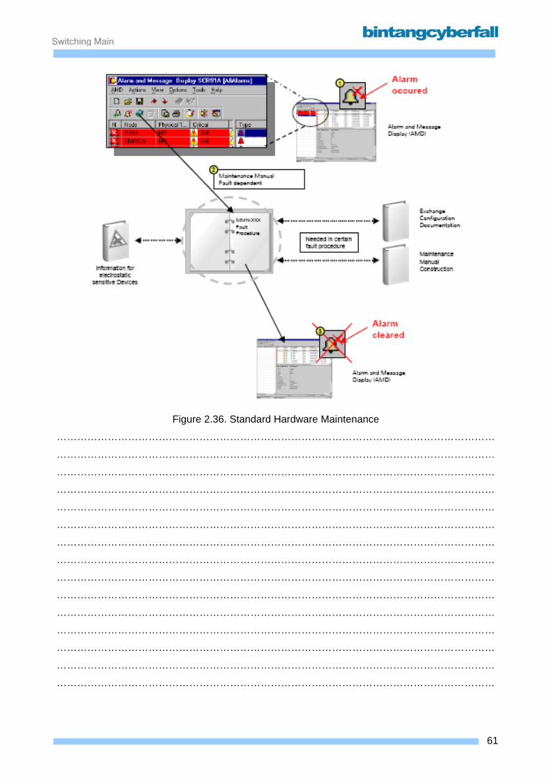
Switching Maintenance
Figure 2.36. Standard Hardware Maintenance
…………………………………………………………………………………………………………………
…………………………………………………………………………………………………………………
…………………………………………………………………………………………………………………
…………………………………………………………………………………………………………………
…………………………………………………………………………………………………………………
…………………………………………………………………………………………………………………
…………………………………………………………………………………………………………………
…………………………………………………………………………………………………………………
…………………………………………………………………………………………………………………
…………………………………………………………………………………………………………………
…………………………………………………………………………………………………………………
…………………………………………………………………………………………………………………
…………………………………………………………………………………………………………………
…………………………………………………………………………………………………………………
…………………………………………………………………………………………………………………
61BCCN2200 © 2007 Bintang CyberFall

Switching Maintenance
The maintenance manuals are intended for use as guides to programmed standard HW
maintenance and for use as a reference. Maintenance manuals are available for all HW system
units for which the standard maintenance procedure applies. A maintenance manual on software
is also available but is not described in this section.
There are two different kinds of manuals used for maintenance applications:
1. Maintenance manuals for the different HW system units The maintenance manuals for the different hardware contains procedures for standard HW fault
clearance. It contains the following sections:
• Introduction
The introduction contains important general information such as how the manual fits into the
maintenance manual concept, how to interpret an alarm report, a description of the elements
which make up a fault clearance procedure and an explanation of symbols used.
• List of Procedures
This section lists the fault clearance procedures. The maintenance technician who branched to
the required maintenance manual on the basis of a system fault message starts the procedure
in the block designated as "1". The technician follows any further instructions in this procedure
which contain command inputs, queries from system responses, branches to other blocks and
module interchange.
• Tables
This section contains important reference information which is also used during a fault
clearance procedure. This section includes a list of suspect modules for fault clearance.
2. Construction manual The Construction Manual describes how the HW is embedded into the system. It contains the
following sections:
• Racks
This section contains information on how to combine frames to racks. Further it shows the
allocation of fuses to modules.
62BCCN2200 © 2007 Bintang CyberFall

Switching Maintenance
• Frames
This section contains all allowed modules for each frame including the mounting locations.
Additionally it shows the back plane and the cabling.
For LTG it comprises tables with LTU-types and LTU-numbers.
• Modules
For all modules which have maintenance relevant HW elements the front layout as
well as switches on the board itself (if any) are documented.
63BCCN2200 © 2007 Bintang CyberFall
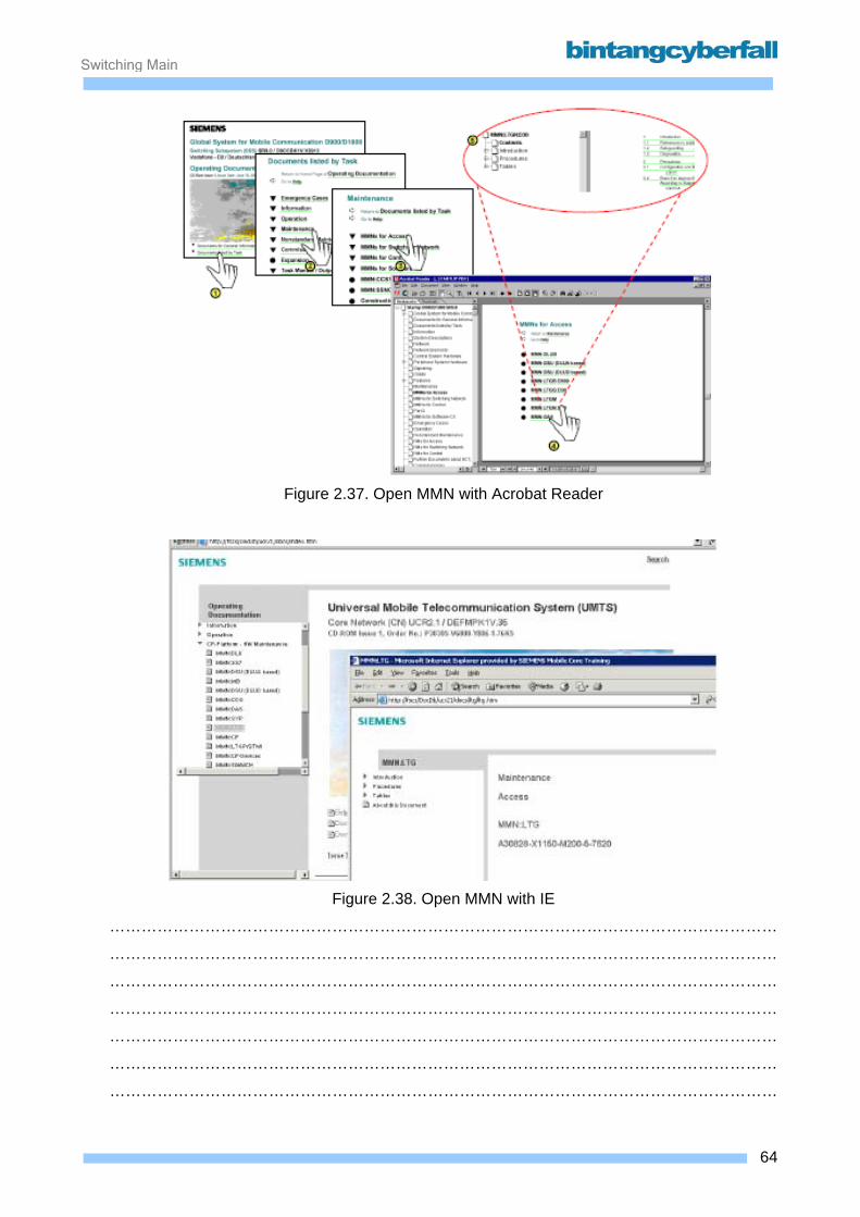
Switching Maintenance
Figure 2.37. Open MMN with Acrobat Reader
Figure 2.38. Open MMN with IE
………………………………………………………………………………………………………………
………………………………………………………………………………………………………………
………………………………………………………………………………………………………………
………………………………………………………………………………………………………………
………………………………………………………………………………………………………………
………………………………………………………………………………………………………………
………………………………………………………………………………………………………………
64BCCN2200 © 2007 Bintang CyberFall
Switching Maintenance
MMN using Acrobat Reader Use the navigation pane on the left to find the right procedure for fault clearance. It can be
accessed directly in the tree by clicking through the branches, or by selecting the 'Procedures'
section, which opens the list of procedures in the main Window. Once the right procedure is found,
follow the instructions given.
Commands which have to be executed are linked to either the workbench of the Switch
Commander (command is loaded and has only to be filled with the right parameter values), or the
Task Manual to get the complete Command description (standard installation). This link
functionality can be changed manually if the right Acrobat Reader version is installed.
65BCCN2200 © 2007 Bintang CyberFall
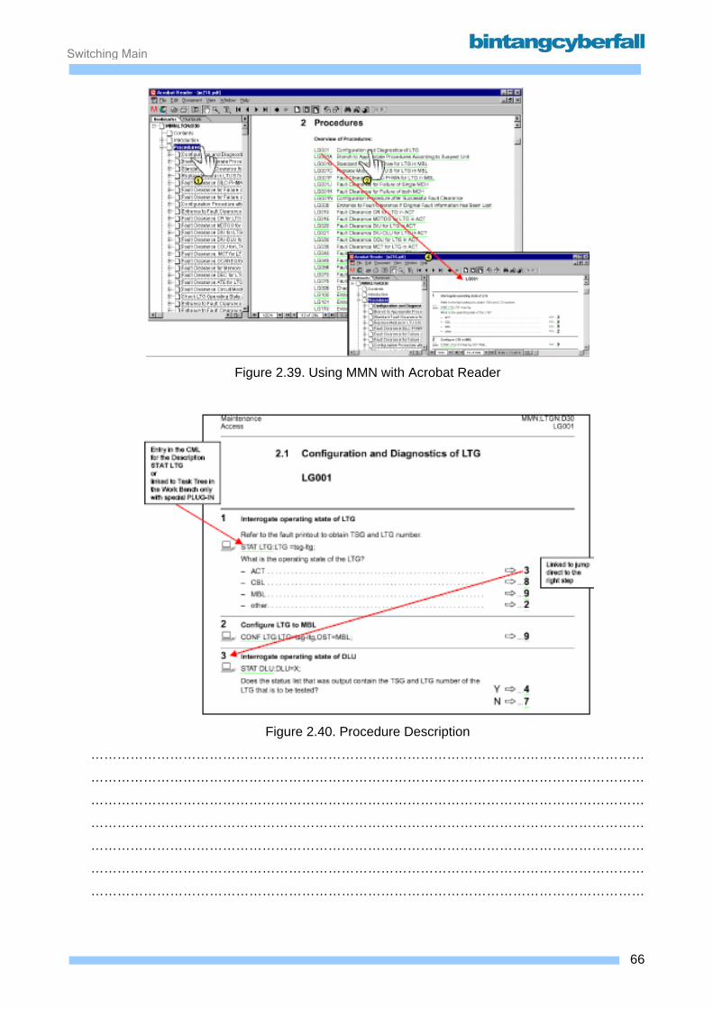
Switching Maintenance
Figure 2.39. Using MMN with Acrobat Reader
Figure 2.40. Procedure Description
………………………………………………………………………………………………………………
………………………………………………………………………………………………………………
………………………………………………………………………………………………………………
………………………………………………………………………………………………………………
………………………………………………………………………………………………………………
………………………………………………………………………………………………………………
………………………………………………………………………………………………………………
66BCCN2200 © 2007 Bintang CyberFall
Switching Maintenance
Mechanical design The Exchange Configuration Documents in contrast to the Electronic Documentation describes the
site specific part of the documentation. Here, the complete hardware configuration, including
Racks, Frames and Modules is listed. Even the cabling and some database relevant information is
given.
Hardware definition The following terms are used for defining the hardware configuration:
• Rack row
It is possible to install one or more network elements of the same or different types in a single
installation room. The individual installation units are installed in rows. Such a row is referred to
as a rack row. Rack rows inside a room are assigned a rack row number to make it possible to
locate individual rows during maintenance.
• Rack
A rack is a single subunit inside a rack row. A rack has two doors on both the front and rear side
which provide access to HW modules or rack cabling. A rack is identified using the rack number.
To find the corresponding rack row and room (more than one room is possible, a special number
is used: The Rack Position Number (ROOM+ROW+RACK). • Frame
Frames are located inside a rack. A frame consists of a metal frame which serves as the
mechanical support, plastic shelves on the front side for holding the hardware modules, and a
multilayer backplane on the back side used for electric connections inside the frame and for
connecting cables to other frames or external equipment. Depending on the size of the
backplane, a frame can hold one or two horizontal rows of modules. A frame is identified by its
so-called "mounting unit" or MUT. The MUT numbers the individual horizontal sections inside a
rack from top to bottom consecutively.
• Module
HW modules are located inside a frame. Module rows inside an MUT are identified by the letter
A or C to facilitate the location of the modules even in frames containing multiple rows. Individual
modules inside a module row can be located using the "module location" or MOLOC number
stamped onto the metal frame supports.
67BCCN2200 © 2007 Bintang CyberFall

Switching Maintenance
To find the module in a rack and frame a special number is used: The Mounting position of Module Number (MUT+MODULE ROW+MOLOC).
68BCCN2200 © 2007 Bintang CyberFall

Switching Maintenance
Figure 2.41. Mechanical Design
………………………………………………………………………………………………………………
………………………………………………………………………………………………………………
………………………………………………………………………………………………………………
………………………………………………………………………………………………………………
………………………………………………………………………………………………………………
………………………………………………………………………………………………………………
………………………………………………………………………………………………………………
………………………………………………………………………………………………………………
………………………………………………………………………………………………………………
………………………………………………………………………………………………………………
………………………………………………………………………………………………………………
………………………………………………………………………………………………………………
………………………………………………………………………………………………………………
………………………………………………………………………………………………………………
………………………………………………………………………………………………………………
………………………………………………………………………………………………………………
………………………………………………………………………………………………………………
………………………………………………………………………………………………………………
………………………………………………………………………………………………………………
69BCCN2200 © 2007 Bintang CyberFall
Switching Maintenance
The different kinds of module frames As mentioned previously, module rows inside a frame are using letters. However the letter
designation used depends on whether the backplane structure is based on SIVAPAC or SIPAC
technology. Numbering of the module location (MOLOC) also depends on the structure of the
backplane.
SIVAPAC single row frame (e.g. LTG G) Module row is generally designated as A Module location is numbered from 1 to 126
SIVAPAC double row frame (e.g. DSU) The upper module row is designated as A and the lower module row as C Module location is
numbered from 1 to 126
SIPAC single row frames only (e.g. CP113C) Module row is always designated as C Module location is numbered from 101 to 349
This numbering makes more sense when looking at the plug positions on the backplane. The
SIVAPAC double row frame e.g. uses plug positions A and B for the upper row, C and D for the
lower row.
70BCCN2200 © 2007 Bintang CyberFall
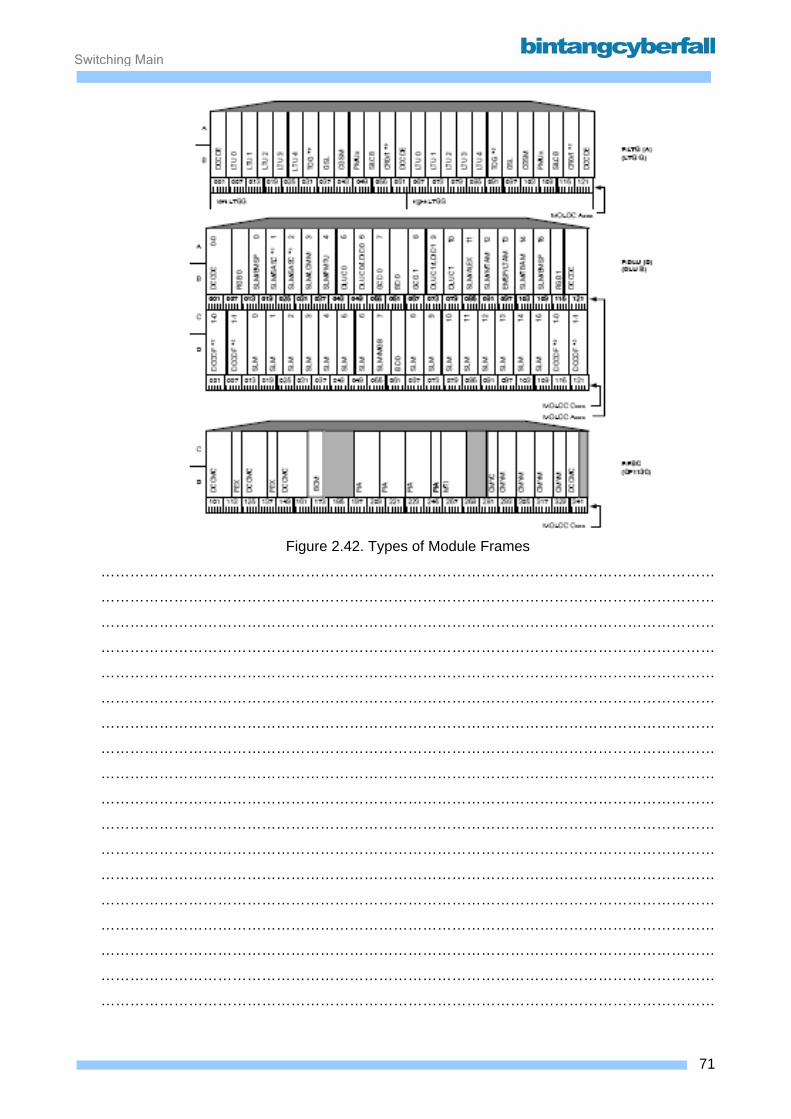
Switching Maintenance
Figure 2.42. Types of Module Frames
………………………………………………………………………………………………………………
………………………………………………………………………………………………………………
………………………………………………………………………………………………………………
………………………………………………………………………………………………………………
………………………………………………………………………………………………………………
………………………………………………………………………………………………………………
………………………………………………………………………………………………………………
………………………………………………………………………………………………………………
………………………………………………………………………………………………………………
………………………………………………………………………………………………………………
………………………………………………………………………………………………………………
………………………………………………………………………………………………………………
………………………………………………………………………………………………………………
………………………………………………………………………………………………………………
………………………………………………………………………………………………………………
………………………………………………………………………………………………………………
………………………………………………………………………………………………………………
………………………………………………………………………………………………………………
71BCCN2200 © 2007 Bintang CyberFall
Switching Maintenance
ECD/ESD for standard HW maintenance The Exchange Configuration Documentation (paper) or the Electronic Site Documentation (HTML)
includes information required for standard HW fault clearance. Always refer to this information
during fault clearance (e.g. to avoid plugging a HW module into the incorrect module slot which
could cause irreparable damage to the module or backplane)
Layout list rack, layout plan and equipment list rack are required for standard fault clearance. Laying List: Rack (LL:Rack)
The rack layout shows the application and numbering of individual racks inside one or more rack
rows of a network element. Refer to the REMARKS column for the system specific numbering of
HW units installed in individual racks. A six digit number has been entered in the RACK POS.NO
column which shows the position of a rack inside the system room and rack row. The RACK
POS.NO consists of the following:
digits 1 - 2 : room number
digits 3 - 4 : rack row number
digits 5 - 6 : rack number
Example: You receive an alarm message containing an error indication from DSU 10 / Module 0-1. You refer to the ECD for the corresponding network node and look for DSU 10 in the LL:Rack.
In the DESIGNATION column you find the designation R:DEVB/DSU/DLU. I.e. this is a combined
rack which contains special CP components (Magnetic Tape Device) and a unit DSU and DLU.
The RACK POS.NO column lists the location of the rack with the faulty DSU: 010101. You use this
location number to find the affected rack in the layout plan and to find the faulty module in the
equipment list rack (EL:R).
If the LL:Rack does not give enough information about e.g. the LTG numbering, the LL:Shelf can
be used additionally. There all the periphery units (LTG/DSU) are listed, sorted according to the
LTG/DSU numbers, with Rack Position Number and Mounting Unit.
72BCCN2200 © 2007 Bintang CyberFall

Switching Maintenance
Figure 2.43. LL: Rack
………………………………………………………………………………………………………………
………………………………………………………………………………………………………………
………………………………………………………………………………………………………………
………………………………………………………………………………………………………………
………………………………………………………………………………………………………………
………………………………………………………………………………………………………………
………………………………………………………………………………………………………………
………………………………………………………………………………………………………………
………………………………………………………………………………………………………………
………………………………………………………………………………………………………………
………………………………………………………………………………………………………………
………………………………………………………………………………………………………………
………………………………………………………………………………………………………………
………………………………………………………………………………………………………………
………………………………………………………………………………………………………………
………………………………………………………………………………………………………………
………………………………………………………………………………………………………………
………………………………………………………………………………………………………………
73BCCN2200 © 2007 Bintang CyberFall
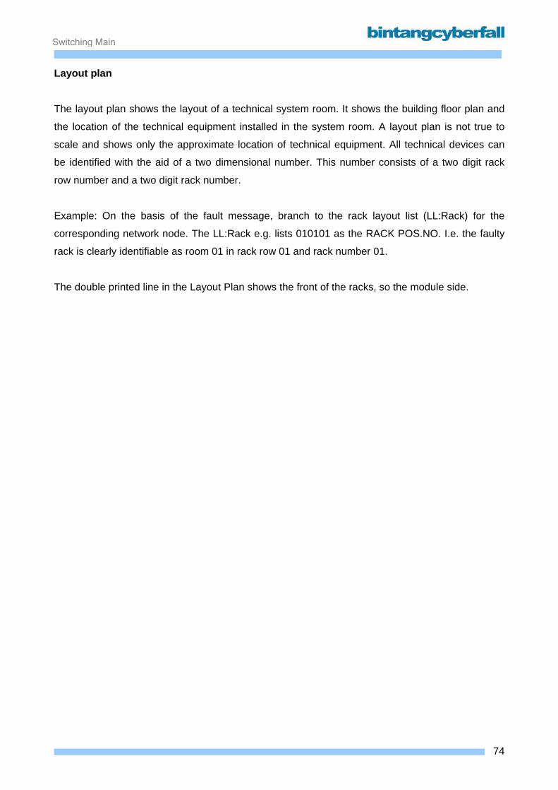
Switching Maintenance
Layout plan The layout plan shows the layout of a technical system room. It shows the building floor plan and
the location of the technical equipment installed in the system room. A layout plan is not true to
scale and shows only the approximate location of technical equipment. All technical devices can
be identified with the aid of a two dimensional number. This number consists of a two digit rack
row number and a two digit rack number.
Example: On the basis of the fault message, branch to the rack layout list (LL:Rack) for the
corresponding network node. The LL:Rack e.g. lists 010101 as the RACK POS.NO. I.e. the faulty
rack is clearly identifiable as room 01 in rack row 01 and rack number 01.
The double printed line in the Layout Plan shows the front of the racks, so the module side.
74BCCN2200 © 2007 Bintang CyberFall
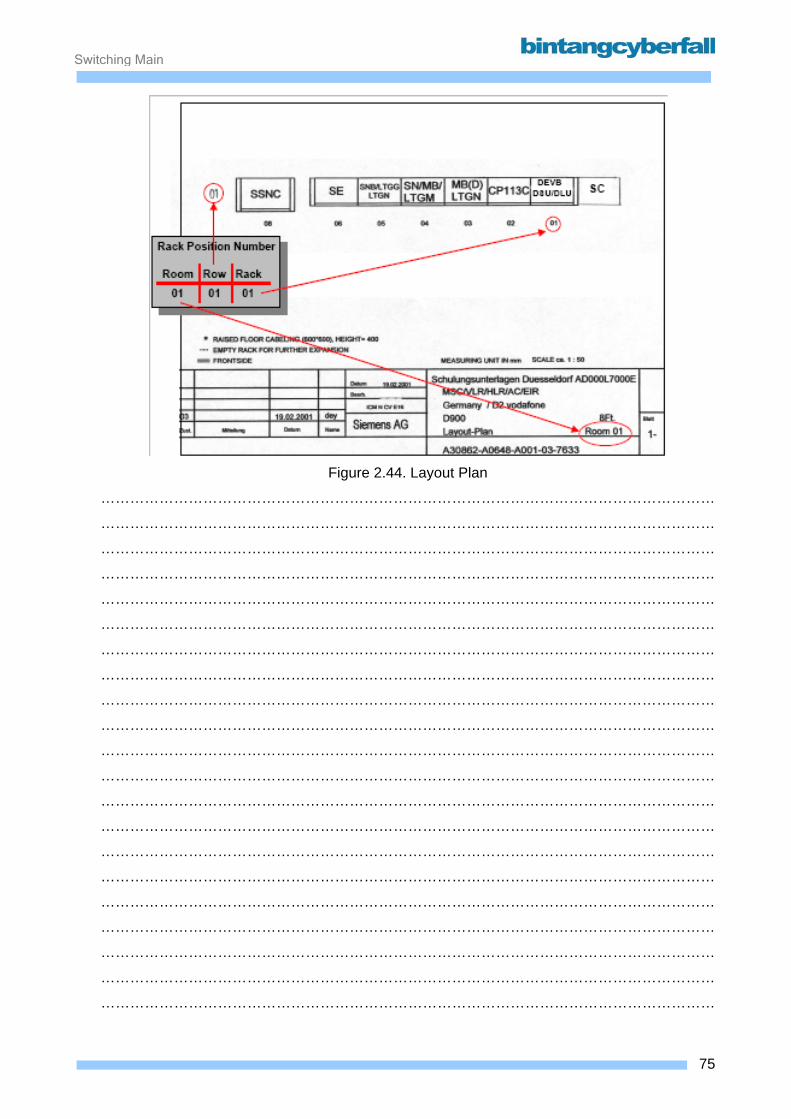
Switching Maintenance
Figure 2.44. Layout Plan
………………………………………………………………………………………………………………
………………………………………………………………………………………………………………
………………………………………………………………………………………………………………
………………………………………………………………………………………………………………
………………………………………………………………………………………………………………
………………………………………………………………………………………………………………
………………………………………………………………………………………………………………
………………………………………………………………………………………………………………
………………………………………………………………………………………………………………
………………………………………………………………………………………………………………
………………………………………………………………………………………………………………
………………………………………………………………………………………………………………
………………………………………………………………………………………………………………
………………………………………………………………………………………………………………
………………………………………………………………………………………………………………
………………………………………………………………………………………………………………
………………………………………………………………………………………………………………
………………………………………………………………………………………………………………
………………………………………………………………………………………………………………
………………………………………………………………………………………………………………
………………………………………………………………………………………………………………
75BCCN2200 © 2007 Bintang CyberFall
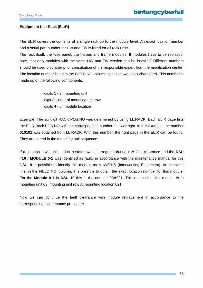
Switching Maintenance
Equipment List Rack (EL:R)
The EL:R covers the contents of a single rack up to the module level. An exact location number
and a serial part number for HW and FW is listed for all rack units.
The rack itself, the fuse panel, the frames and frame modules. If modules have to be replaced,
note, that only modules with the same HW and FW version can be installed. Different numbers
should be used only after prior consultation of the responsible expert from the modification center.
The location number listed in the FIELD NO. column contains two to six characters. This number is
made up of the following components:
digits 1 - 2 : mounting unit
digit 3 : letter of mounting unit row
digits 4 - 6 : module location
Example: The six digit RACK POS.NO was determined by using LL:RACK. Each EL:R page lists
the EL:R Rack POS.NO with the corresponding number at lower right. In this example, the number
010101 was obtained from LL:RACK. With this number, the right page in the EL:R can be found.
They are sorted in the mounting unit sequence.
If a diagnostic was initiated or a status was interrogated during HW fault clearance and the DSU =10 / MODULE 0-1 was identified as faulty in accordance with the maintenance manual for this
DSU, it is possible to identify this module as M:IWE:HS (Interworking Equipment). In the same
line, in the FIELD NO. column, it is possible to obtain the exact location number for this module.
For the Module 0-1 in DSU 10 this is the number 03A021. This means that the module is in
mounting unit 03, mounting unit row A, mounting location 021.
Now we can continue the fault clearance with module replacement in accordance to the
corresponding maintenance procedure.
76BCCN2200 © 2007 Bintang CyberFall
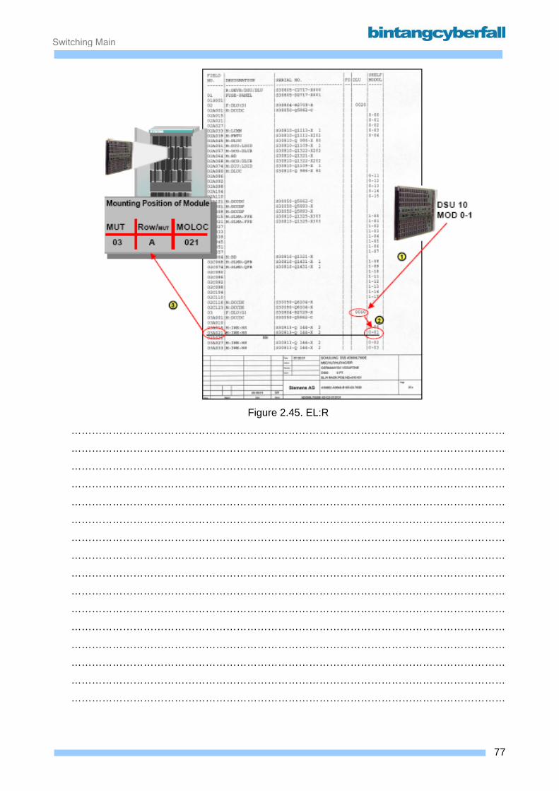
Switching Maintenance
Figure 2.45. EL:R
………………………………………………………………………………………………………………
………………………………………………………………………………………………………………
………………………………………………………………………………………………………………
………………………………………………………………………………………………………………
………………………………………………………………………………………………………………
………………………………………………………………………………………………………………
………………………………………………………………………………………………………………
………………………………………………………………………………………………………………
………………………………………………………………………………………………………………
………………………………………………………………………………………………………………
………………………………………………………………………………………………………………
………………………………………………………………………………………………………………
………………………………………………………………………………………………………………
………………………………………………………………………………………………………………
………………………………………………………………………………………………………………
………………………………………………………………………………………………………………
77BCCN2200 © 2007 Bintang CyberFall

Switching Maintenance
3. Switching Subsystem – Access Function Contents 3.1. Line Trunk Group....................................................................................................................... 2
3.1. 1. Function ............................................................................................................................. 3 3.1.2. Hardware and Location ....................................................................................................... 7
3.2. Data Service Unit..................................................................................................................... 28 3.2.1. Function ............................................................................................................................ 29 3.2.2. Hardware and Location ..................................................................................................... 31
1BCCN2200 © 2007 Bintang CyberFall

Switching Maintenance
3.1. Line Trunk Group
2BCCN2200 © 2007 Bintang CyberFall
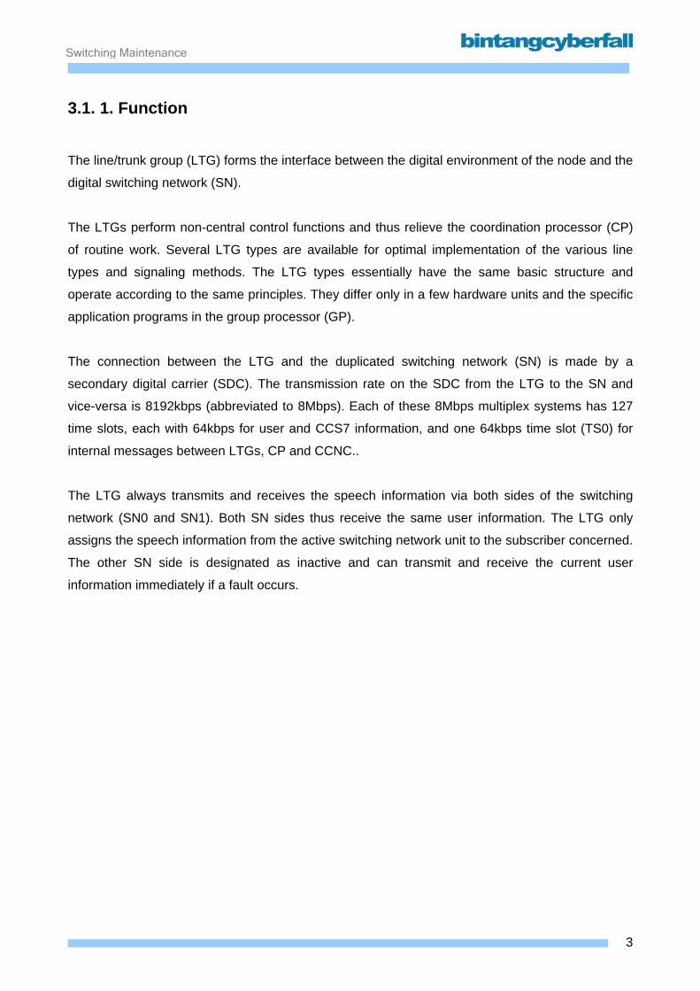
Switching Maintenance
3.1. 1. Function
The line/trunk group (LTG) forms the interface between the digital environment of the node and the
digital switching network (SN).
The LTGs perform non-central control functions and thus relieve the coordination processor (CP)
of routine work. Several LTG types are available for optimal implementation of the various line
types and signaling methods. The LTG types essentially have the same basic structure and
operate according to the same principles. They differ only in a few hardware units and the specific
application programs in the group processor (GP).
The connection between the LTG and the duplicated switching network (SN) is made by a
secondary digital carrier (SDC). The transmission rate on the SDC from the LTG to the SN and
vice-versa is 8192kbps (abbreviated to 8Mbps). Each of these 8Mbps multiplex systems has 127
time slots, each with 64kbps for user and CCS7 information, and one 64kbps time slot (TS0) for
internal messages between LTGs, CP and CCNC..
The LTG always transmits and receives the speech information via both sides of the switching
network (SN0 and SN1). Both SN sides thus receive the same user information. The LTG only
assigns the speech information from the active switching network unit to the subscriber concerned.
The other SN side is designated as inactive and can transmit and receive the current user
information immediately if a fault occurs.
3BCCN2200 © 2007 Bintang CyberFall
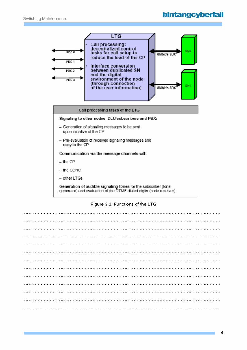
Switching Maintenance
Figure 3.1. Functions of the LTG
…………………………………………………………………………………………………………………
…………………………………………………………………………………………………………………
…………………………………………………………………………………………………………………
…………………………………………………………………………………………………………………
…………………………………………………………………………………………………………………
…………………………………………………………………………………………………………………
…………………………………………………………………………………………………………………
…………………………………………………………………………………………………………………
…………………………………………………………………………………………………………………
…………………………………………………………………………………………………………………
…………………………………………………………………………………………………………………
…………………………………………………………………………………………………………………
…………………………………………………………………………………………………………………
4BCCN2200 © 2007 Bintang CyberFall

Switching Maintenance
LTG types in D900 In the D900 switch all LTG applications belong to the functional type "B".
Depending on the application and age of the LTG the following hardware types may be used in the
D900 system:
• LTGM
• LTGN
• LTGP
5BCCN2200 © 2007 Bintang CyberFall
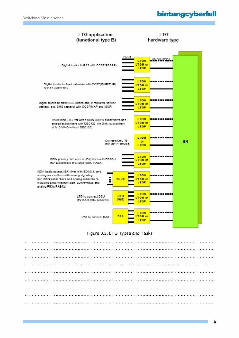
Switching Maintenance
Figure 3.2. LTG Types and Tasks
…………………………………………………………………………………………………………………
…………………………………………………………………………………………………………………
…………………………………………………………………………………………………………………
…………………………………………………………………………………………………………………
…………………………………………………………………………………………………………………
…………………………………………………………………………………………………………………
…………………………………………………………………………………………………………………
…………………………………………………………………………………………………………………
…………………………………………………………………………………………………………………
6BCCN2200 © 2007 Bintang CyberFall

Switching Maintenance
3.1.2. Hardware and Location
The various LTG types basically have the same internal structure and consist of the following
physical or logical units. Depending on the LTG type, these units can be found on different
hardware modules:
Group Processor The group processor (GP) matches the incoming information from the surrounding network node
area to the internal message format of the system and controls all the parts within the LTG.
Link Interface Unit (LIU) The LIU connects the LTG to the duplicated SN (SN0 and SN1). The LIU converts the 8Mbps
multiplex highway arriving from the GS into two parallel 8Mbps SDCs to the SN. Conversely, it
receives the user information from the switching network-half designated as active via two parallel
SDCs and forwards it to the GS. The LIU synchronizes the information arriving over SDCs from
the SN with the LTG-internal clock system and feeds the node clock (8192kHz) to the group clock
generator of the LTG. It extracts the CP commands from the message channel (TS0) and forwards
them to the GP. In the opposite direction, the LIU transfers GP messages to the CP.
After each connection setup, the LIU verifies correct through-connection in the SN with the aid of
the cross-office check (COC). For this purpose, the calling LIU sends a test bit sequence that is
reflected by the LIU of the called side. If the transmitted and reflected bit patterns are identical, the
established connection is switched through to the subscriber.
Group Clock Generator (GCG) The GCG supplies the LTG with the required control clocks. The crystal oscillator in the GCG is
synchronized with a signal derived from the system clock in the LIU via a phase-locked loop.
Signaling Link Control (SILC) part The Signaling Link Control (SILC) part functions as an input/output processor. The SILC is used to
connect a number of signaling channels via which either the protocol for DLU access (DLU
protocol) or the ISDN D-channel protocol for the primary access (PA protocol) can be handled.
The transmission protocols are based on the HDLC procedure.
On the LTG side, the SILC completes the layer-2 functions of signaling protocols (synchronization,
error detection, error handling) and thereby guarantees securemessage exchange between
peripheral units and the GP.
7BCCN2200 © 2007 Bintang CyberFall
Switching Maintenance
Figure 3.3. Internal Structure of LTG
…………………………………………………………………………………………………………………
…………………………………………………………………………………………………………………
…………………………………………………………………………………………………………………
…………………………………………………………………………………………………………………
…………………………………………………………………………………………………………………
…………………………………………………………………………………………………………………
…………………………………………………………………………………………………………………
…………………………………………………………………………………………………………………
…………………………………………………………………………………………………………………
…………………………………………………………………………………………………………………
…………………………………………………………………………………………………………………
…………………………………………………………………………………………………………………
…………………………………………………………………………………………………………………
…………………………………………………………………………………………………………………
…………………………………………………………………………………………………………………
…………………………………………………………………………………………………………………
…………………………………………………………………………………………………………………
8BCCN2200 © 2007 Bintang CyberFall

Switching Maintenance
Signaling Unit (SU) The SU is a logical unit of the LTG. Physically, the following subunits are possible:
• Code Receiver (CR)
The CR receives and detects multifrequency signals (DTMF, MFC-R2, MFC-R1,).
• Tone Generator (TOG)
The TOG generates the audible tones required for all line/trunk units (LTU) and the frequencies
needed for multifrequency dialing (MFC).
• Receiver Module for Continuity Check (RM:CTC)
The RM:CTC is necessary for testing CCS7 trunks.
Line/Trunk Unit (LTU) The LTU is a logical unit of the LTG. It contains different modules for special tasks.
Possible module types are:
• Digital Interface Unit (DIU)
The DIU is used to connect PDC systems like PCM30 or PCM24.
• Local DLU/DSU Interface (LDI) (1)
The LDI is used to connect a local DLU/DSU by a 4 Mbps carrier
• Conference Unit (COUC for LTGM/N)
Multiparty conferences require the conference unit. The COUB module can handle four
conferences with up to eight subscribers each, the new COUC module has 32 ports, which can
be used in any combination (e.g. one conference with 14 subscribers and two with 9 subscribers.
Additionally, the COUC has on board echo compensation.
• Digital Echo Compensator in D900 (DEC)
A DEC is necessary for connections between mobile and fixed networks to compensate the
reflection and delay occurring with these connections.
• Operationally Controlled Announcement Equipment (OCANEQ)
9BCCN2200 © 2007 Bintang CyberFall
Switching Maintenance
The OCANEQ is used for standard and individual announcements. It can be controlled by the
switch or by subscriber inputs (OCANEQ and Code Receivers as part of an User Interactive
Dialog UI LTG).
• Code Receiver
Additionally to the Signal Unit SU the LTU may also contain CR: Different CR types are possible,
e.g. for MFC:R2 or push-button dialing.
• MDTOG
This module is used to deliver the A-party number to analog wired subscribers of the exchange.
The used method is called Frequency Shift Key FSK. A MDTOG can be connected via SN to any
analog DLU port of the EWSD exchange (pool solution).
Group Switch The GS is a non-blocking space-time stage for 512 channels. The GS interconnects the LTU, SU,
LIU and optional the SILC. The speech data can be attenuated for each channel in eight stages.
Up to 64 conferences (three subscribers and audible tones) are possible.
• GS for LTG with functional type B:
Beside the connection to LIU (8 Mbps), to the SU (2x2Mbps to TOG and 2Mbps to CR) and to
the SILC the GS offers 8x32 ports for 8 LTU. How many of the LTU0-7 can be equipped with HW
modules depends on the LTG HW type. The remaining LTUs can be used for specific
applications, which do not require HW.
• GS for LTG with functional type C:
Beside the connection to LIU (8 Mbps) and to the SU (2x2Mbps to TOG and 2Mbps to CR) the
GS offers 4x32 ports for 4 LTU. These LTU0-3 are normally used as DIU.
10BCCN2200 © 2007 Bintang CyberFall
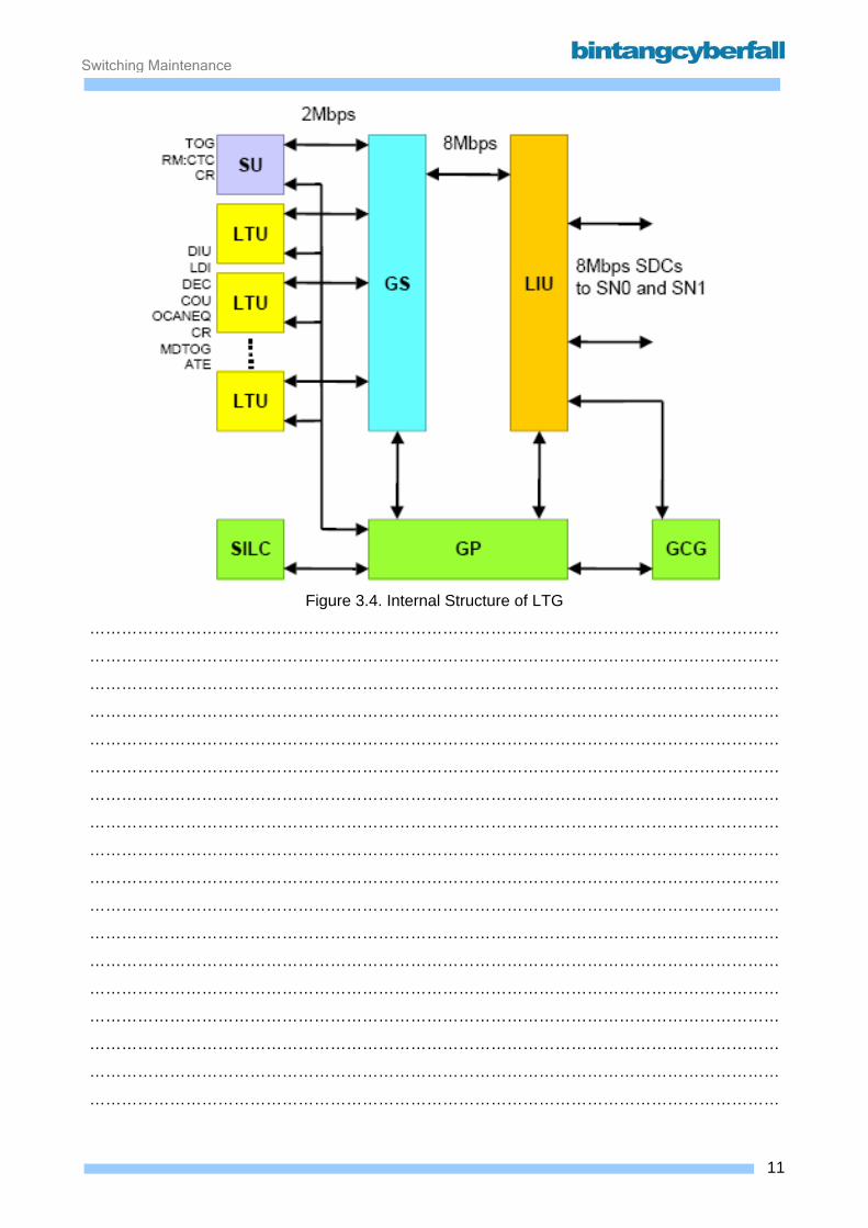
Switching Maintenance
Figure 3.4. Internal Structure of LTG
…………………………………………………………………………………………………………………
…………………………………………………………………………………………………………………
…………………………………………………………………………………………………………………
…………………………………………………………………………………………………………………
…………………………………………………………………………………………………………………
…………………………………………………………………………………………………………………
…………………………………………………………………………………………………………………
…………………………………………………………………………………………………………………
…………………………………………………………………………………………………………………
…………………………………………………………………………………………………………………
…………………………………………………………………………………………………………………
…………………………………………………………………………………………………………………
…………………………………………………………………………………………………………………
…………………………………………………………………………………………………………………
…………………………………………………………………………………………………………………
…………………………………………………………………………………………………………………
…………………………………………………………………………………………………………………
…………………………………………………………………………………………………………………
11BCCN2200 © 2007 Bintang CyberFall

Switching Maintenance
The LTGM The LTGM is one of old standard type for EWSD and D900 systems. It is used for all tasks except
OCANEQ. Only three modules are necessary for a complete LTGM with four PCM systems
connected.
• The 4 PCM are combined together with the current converter on the module DIU120A. Logically,
this module is treated as LTU0 to LTU3 with ordinary DIU30 modules. Optionally, this module
can be replaced by a DIU:LDIM module to connect to a DLU or DSU via a 4Mbps local DLU
interface.
• The GPL module (group processor for LTGM) holds the PMU and, if required, the SILC
functionality. Two different GP modules are used:
GPL, Group processor for LTGM without SILC function
GPLS, Group processor for LTGM with SILC function
• The GSM (group switch for LTGM) is a combination of GSL, TOG, RM:CTC, CR and GCG.
Depending on the available on board components, different GSM modules are used. The last
three digits of the GSMabc modules define the module type:
Additional fourth module in LTGM: the LTU:S of LTGM in B function D900: Additionally, a digital echo compensator (DEC120) or a large conference unit (COUC) can
be installed as LTU:S if the LTG is used for connecting the PSTN.
12BCCN2200 © 2007 Bintang CyberFall
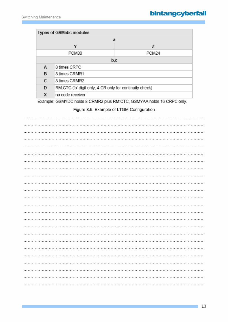
Switching Maintenance
Figure 3.5. Example of LTGM Configuration
…………………………………………………………………………………………………………………
…………………………………………………………………………………………………………………
…………………………………………………………………………………………………………………
…………………………………………………………………………………………………………………
…………………………………………………………………………………………………………………
…………………………………………………………………………………………………………………
…………………………………………………………………………………………………………………
…………………………………………………………………………………………………………………
…………………………………………………………………………………………………………………
…………………………………………………………………………………………………………………
…………………………………………………………………………………………………………………
…………………………………………………………………………………………………………………
…………………………………………………………………………………………………………………
…………………………………………………………………………………………………………………
…………………………………………………………………………………………………………………
…………………………………………………………………………………………………………………
…………………………………………………………………………………………………………………
…………………………………………………………………………………………………………………
…………………………………………………………………………………………………………………
…………………………………………………………………………………………………………………
…………………………………………………………………………………………………………………
…………………………………………………………………………………………………………………
…………………………………………………………………………………………………………………
…………………………………………………………………………………………………………………
13BCCN2200 © 2007 Bintang CyberFall

Switching Maintenance
Figure 3.6. Structure of LTGM
…………………………………………………………………………………………………………………
…………………………………………………………………………………………………………………
…………………………………………………………………………………………………………………
…………………………………………………………………………………………………………………
…………………………………………………………………………………………………………………
…………………………………………………………………………………………………………………
…………………………………………………………………………………………………………………
…………………………………………………………………………………………………………………
…………………………………………………………………………………………………………………
…………………………………………………………………………………………………………………
…………………………………………………………………………………………………………………
…………………………………………………………………………………………………………………
…………………………………………………………………………………………………………………
…………………………………………………………………………………………………………………
…………………………………………………………………………………………………………………
…………………………………………………………………………………………………………………
…………………………………………………………………………………………………………………
…………………………………………………………………………………………………………………
14BCCN2200 © 2007 Bintang CyberFall
Switching Maintenance
The LTGN The LTGN is the a current standard type of the LTG.
Only one module makes up a complete LTGN for the basic tasks. The LTGN hardware combines
almost every possible functional unit and this single module, e.g. different code receivers in logical
LTU and SU positions.
Additional second module in LTGM: the LTU:S of LTGN in B function • D900: Additionally, a digital echo compensator (DEC120) or a COUC (Conference Unit C) can be
installed.
• EWSD:
Additionally, a PHMA can be installed as LTU5 if the LTG is used for connecting an Access
Network AN via V5.2 interface. Additionally, a MDTOG can be installed as LTU5 if the LTG is
used for supporting the feature CLIP for analog subscribers.
Additionally, a COUC can be installed as LTU3 to support large conferences Additional LTU:S
modules, like OCANEQ is available.
15BCCN2200 © 2007 Bintang CyberFall
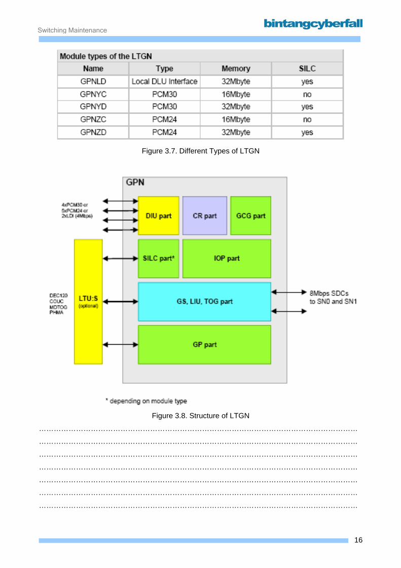
Switching Maintenance
Figure 3.7. Different Types of LTGN
Figure 3.8. Structure of LTGN
…………………………………………………………………………………………………………………
…………………………………………………………………………………………………………………
…………………………………………………………………………………………………………………
…………………………………………………………………………………………………………………
…………………………………………………………………………………………………………………
…………………………………………………………………………………………………………………
…………………………………………………………………………………………………………………
16BCCN2200 © 2007 Bintang CyberFall

Switching Maintenance
The LTGP The successor of the LTGN is the LTGP, which replaces the LTGN for the existing mobile core
applications and supports the same functionality as the LTGN. In the LTGN it was possible to
integrate one LTG functionality on one board. Now, with the LTGP technology, four LTG functions
are concentrated on one board, but nevertheless, they continue to perform like 4 separate LTG's.
It is downwards compatible to older software releases up to and including SR8.
General benefits of LTGP are: • Cost reduction due to high density packaging by use of most modern technology
• Footprint reduction to one quarter by increasing the channel capacity of 1 LTG module by a
factor of 4 (4LTGs on one board)
• Assurance of further deliverability by replacement of older component types.
As default, each LTG operates with its own GP software and handles its own dedicated message
channel via its own SDC connection to the SN. Each LTG has its own set of PCM periphery. This
concept is also implemented in the LTGP, but the hardware realization of the LTGP internal
functions is different. The low access and high process time of the new technology allows firmware
resources to be shared between the four LTGP functions.
The other LTG functions (e.g. GS, DIU, CR, TOG, and SILC) are on the same board and are
controlled by a single IOP processor doing the job for all four LTGP functions.
In some applications, the basic LTG functionality has to be extended with special features, such as
conference unit, echo cancellation, etc. These extra functions for the LTGP are implemented on
the functional unit LTU:S. Since DEC120 and COUC are not released for LTGP, the new DEC480
and the ATCO must be used.
Each LTGP board is provided with only one supplementary board LTU:S. By using the special
feature boards from the LTGN, only one of the four LTGP functions on one board (i.e. LTGP#1)
has access to the feature board that offers the extended functionality. In the other three LTGP
functions only the basic LTG functions can be used. An exception to this rule is the DEC480,
providing echo cancellation for all four LTG functions (480 channels).
It is possible to load different load types in the LTGP functions of one GPP board.
If an LTGN module has a failure, 120 ports are lost. With LTGP, 480 ports are lost.
17BCCN2200 © 2007 Bintang CyberFall
Switching Maintenance
This quantity is still acceptable because with the new technology the MTBF was increased.
The LTGP is prepared to be connected
• electrically via copper lines to the TSG of SN B
• electrically via copper lines to SNMUX A of SN D
• via fiber optics to SNMUX B of SN D (additional backplane-module SNOPT required)
18BCCN2200 © 2007 Bintang CyberFall
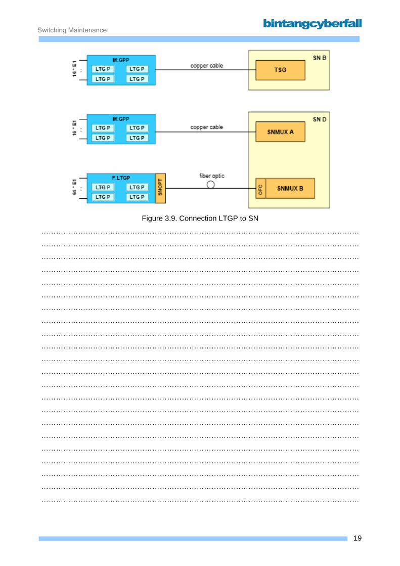
Switching Maintenance
Figure 3.9. Connection LTGP to SN
…………………………………………………………………………………………………………………
…………………………………………………………………………………………………………………
…………………………………………………………………………………………………………………
…………………………………………………………………………………………………………………
…………………………………………………………………………………………………………………
…………………………………………………………………………………………………………………
…………………………………………………………………………………………………………………
…………………………………………………………………………………………………………………
…………………………………………………………………………………………………………………
…………………………………………………………………………………………………………………
…………………………………………………………………………………………………………………
…………………………………………………………………………………………………………………
…………………………………………………………………………………………………………………
…………………………………………………………………………………………………………………
…………………………………………………………………………………………………………………
…………………………………………………………………………………………………………………
…………………………………………………………………………………………………………………
…………………………………………………………………………………………………………………
…………………………………………………………………………………………………………………
…………………………………………………………………………………………………………………
…………………………………………………………………………………………………………………
…………………………………………………………………………………………………………………
19BCCN2200 © 2007 Bintang CyberFall

Switching Maintenance
LTGP hardware - M:GPP The basic LTG functionality of such 4 LTGP functions is implemented on one baseboard named
Group Processor, type P (GPP). There is big impact to the GP-unit, because only one GP-processor is used, which executes the
GP-SW of the four LTG-units during individually assigned time slots.
The realization of this concept is covered by a new ASIC A:GPCP and a modification in special
parts of the GP-FW.
HW architecture: • Concentration of 4 "classic" LTG-function-units (LTGN) into one module GPP (2 new ASIC's )
• LTGP with GPP module covers PCM30- applications (LTGS with GPS module is planned to
cover SDH-applications, STM1 interface)
• Support of electrical (SN B) and optical (SN D) interface to SN
• All basic peripheral functions are controlled by one single microprocessor
• All CR + MDTOG functions are concentrated in two DSPs on board
• All optional functions are implemented on separate modules (i.e. LTU:S)
• The base module and only one optional module form the base LTGP core (LTGP unit)
The following module types are possible, but only M:GPPYG is released for mobile applications:
20BCCN2200 © 2007 Bintang CyberFall
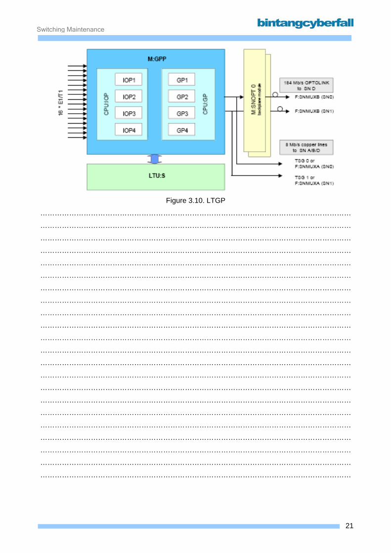
Switching Maintenance
Figure 3.10. LTGP
…………………………………………………………………………………………………………………
…………………………………………………………………………………………………………………
…………………………………………………………………………………………………………………
…………………………………………………………………………………………………………………
…………………………………………………………………………………………………………………
…………………………………………………………………………………………………………………
…………………………………………………………………………………………………………………
…………………………………………………………………………………………………………………
…………………………………………………………………………………………………………………
…………………………………………………………………………………………………………………
…………………………………………………………………………………………………………………
…………………………………………………………………………………………………………………
…………………………………………………………………………………………………………………
…………………………………………………………………………………………………………………
…………………………………………………………………………………………………………………
…………………………………………………………………………………………………………………
…………………………………………………………………………………………………………………
…………………………………………………………………………………………………………………
…………………………………………………………………………………………………………………
…………………………………………………………………………………………………………………
…………………………………………………………………………………………………………………
…………………………………………………………………………………………………………………
21BCCN2200 © 2007 Bintang CyberFall
Switching Maintenance
DEC 480 In SR 10 the LTGN may be replaced by the new LTGP. The GPP-board has four times the number
of traffic channels than the formerly used GPN-board: 480 channels instead of 120.
Since echo compensation is a must in many applications in mobile networks, it is necessary to
have a new DEC module that can serve all 480 channel of one GPP board.
The existing module DEC120 can NOT be plugged into the LTU:S position and work together with
LTGP.
In order to supply all 480 channels of the LTGP with echo cancellers, a new board DEC480 was
developed.
DEC480 may be used in LTGP as echo canceller for 480 channels with a maximum echo delay of
about 63 msec. It may also be used for 120 channels in LTGN or even LTGM.
The DEC480 hard- and firmware is basically the same as for DEC120, implemented four times on
one board. Thus, it behaves exactly as the old DEC120.
No new MML commands were introduced for DEC480.
22BCCN2200 © 2007 Bintang CyberFall
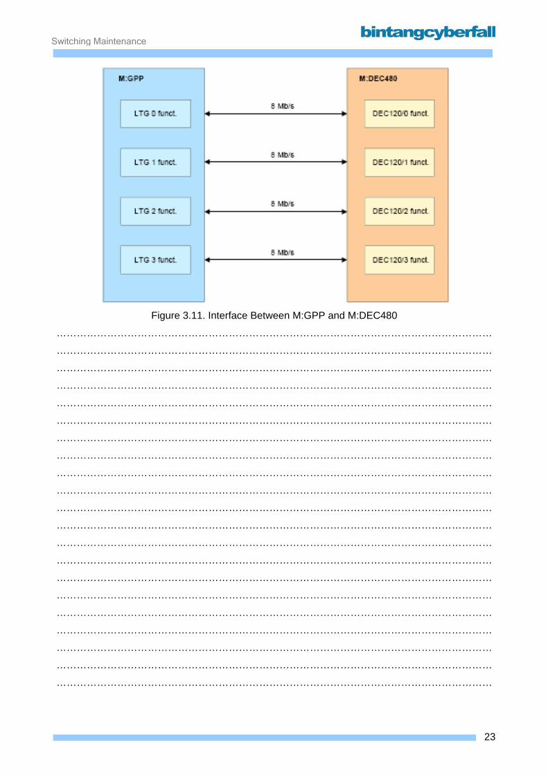
Switching Maintenance
Figure 3.11. Interface Between M:GPP and M:DEC480
…………………………………………………………………………………………………………………
…………………………………………………………………………………………………………………
…………………………………………………………………………………………………………………
…………………………………………………………………………………………………………………
…………………………………………………………………………………………………………………
…………………………………………………………………………………………………………………
…………………………………………………………………………………………………………………
…………………………………………………………………………………………………………………
…………………………………………………………………………………………………………………
…………………………………………………………………………………………………………………
…………………………………………………………………………………………………………………
…………………………………………………………………………………………………………………
…………………………………………………………………………………………………………………
…………………………………………………………………………………………………………………
…………………………………………………………………………………………………………………
…………………………………………………………………………………………………………………
…………………………………………………………………………………………………………………
…………………………………………………………………………………………………………………
…………………………………………………………………………………………………………………
…………………………………………………………………………………………………………………
…………………………………………………………………………………………………………………
23BCCN2200 © 2007 Bintang CyberFall
Switching Maintenance
Frame layouts There are a lot of possible rack types for combining different LTGs with other equipment like the
switching network. Please refer to the maintenance manuals and site-specific documentation for
details.
Frame for LTGM As the LTGM has only three modules (four with the optional LTU:S), five LTGs use one frame
(F:LTGM(A)). Up to 30 LTGM can be installed in one rack. Each LTG has its own current
converter, located on the DIU120A or DIU:LDIM module.
Frame for LTGN There are two different frame types for the LTGN. If the LTU:S function is not needed (ordinary
PCM systems to other network nodes), 16 LTGN can be installed in one frame (F:LTGN(A)). Up to
64 LTGs can be installed in a rack. When the LTU:S is necessary (e.g. DEC or COUC), only eight
LTGs are possible (F:LTGN(B)). Each LTGN has its own on-board current converter.
24BCCN2200 © 2007 Bintang CyberFall

Switching Maintenance
Figure 3.12. Frame for LTGM and LTGN
…………………………………………………………………………………………………………………
…………………………………………………………………………………………………………………
…………………………………………………………………………………………………………………
…………………………………………………………………………………………………………………
…………………………………………………………………………………………………………………
…………………………………………………………………………………………………………………
…………………………………………………………………………………………………………………
…………………………………………………………………………………………………………………
…………………………………………………………………………………………………………………
…………………………………………………………………………………………………………………
…………………………………………………………………………………………………………………
…………………………………………………………………………………………………………………
…………………………………………………………………………………………………………………
25BCCN2200 © 2007 Bintang CyberFall
Switching Maintenance
Frame F:LTGP There are two types of frames for the LTGP namely F:LTGP(A) and F:LTGP(B).
F:LTGP(A) will be used for an 'ordinary' LTG while F:LTGP(B) has the UI-LTG functionality.
The frame F:LTGP(A) houses the modules for 2x 16 LTG functionalities (on 2x 4x M:GPP and
LTU:S). It also provides adaptation systems for external interfaces (power supply, SDC interface,
M:SNOPT).
The backplane of the new F:LTGP(A) is split into 2 separated parts. Each of the two parts takes 4
LTGP units (GPP + LTU:S) and the redundant interface module SNOPT. The modules M:SNOPT
are plugged into SIPAC-HS adaptation systems on the cable side. The advantage is a better
reliability and handling (service, maintenance) in case of a failure in one backplane half.
In this way, the entire frame provides a total of 32 LTG functions. Eight of them provide the
complete functionality range while the remaining 24 are restricted to the basic LTG functions with
exception to the DEC480 that serves for all LTGs on one board.
Due to the high number of cables in a rack only 8-fold PCM cables will be used to the MDF at a
full rack with up to 6x F:LTGP(A). For enlargement of an existing exchange with only a few
F:LTGP a single or double PCM cable may be used too.
Due to the estimated power consumption of the frames a forced cooling is necessary.
26BCCN2200 © 2007 Bintang CyberFall
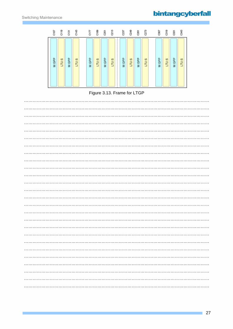
Switching Maintenance
Figure 3.13. Frame for LTGP
…………………………………………………………………………………………………………………
…………………………………………………………………………………………………………………
…………………………………………………………………………………………………………………
…………………………………………………………………………………………………………………
…………………………………………………………………………………………………………………
…………………………………………………………………………………………………………………
…………………………………………………………………………………………………………………
…………………………………………………………………………………………………………………
…………………………………………………………………………………………………………………
…………………………………………………………………………………………………………………
…………………………………………………………………………………………………………………
…………………………………………………………………………………………………………………
…………………………………………………………………………………………………………………
…………………………………………………………………………………………………………………
…………………………………………………………………………………………………………………
…………………………………………………………………………………………………………………
…………………………………………………………………………………………………………………
…………………………………………………………………………………………………………………
…………………………………………………………………………………………………………………
…………………………………………………………………………………………………………………
…………………………………………………………………………………………………………………
…………………………………………………………………………………………………………………
…………………………………………………………………………………………………………………
…………………………………………………………………………………………………………………
…………………………………………………………………………………………………………………
…………………………………………………………………………………………………………………
27BCCN2200 © 2007 Bintang CyberFall

Switching Maintenance
3.2. Data Service Unit
28BCCN2200 © 2007 Bintang CyberFall

Switching Maintenance
3.2.1. Function
The Data Service Unit is needed for data and fax calls to and from mobile subscribers. The DSU
converts the different protocols used to transfer data between personal computers (V.32, V.42,
FAX G3 etc.) to the GSM specific transmission method. The maximum bit rate is 9600bps.
When performing any kind of data call, it is first routed through the DSU and then to the called
subscriber.
For the MSC, the DSU is an external equipment connected to LTGs. For redundancy reasons, a
DSU is usually connected to two LTGs via two PCM cables to each LTG.
29BCCN2200 © 2007 Bintang CyberFall

Switching Maintenance
Figure 3.14. Path Through MSC for Data Call
…………………………………………………………………………………………………………………
…………………………………………………………………………………………………………………
…………………………………………………………………………………………………………………
…………………………………………………………………………………………………………………
…………………………………………………………………………………………………………………
…………………………………………………………………………………………………………………
…………………………………………………………………………………………………………………
…………………………………………………………………………………………………………………
…………………………………………………………………………………………………………………
…………………………………………………………………………………………………………………
…………………………………………………………………………………………………………………
…………………………………………………………………………………………………………………
…………………………………………………………………………………………………………………
…………………………………………………………………………………………………………………
…………………………………………………………………………………………………………………
…………………………………………………………………………………………………………………
…………………………………………………………………………………………………………………
…………………………………………………………………………………………………………………
…………………………………………………………………………………………………………………
30BCCN2200 © 2007 Bintang CyberFall
Switching Maintenance
3.2.2. Hardware and Location
The DSU is divided into the following functional units:
The central functional units are duplicated for redundancy reasons and form the DLU
systems 0 and 1. They consist of:
• Digital Line Unit Controller (DLUC)
The DLUC controls all internal functions of the DSU. A DLUC controls 60 channels on two
PDCs.
• Digital Interface Unit for DLU (DIUD)
The interface between DSU and LTG is the DIUD. Two PDCs can be connected. Instead of the
DIUD, a Digital Interface Unit for local DLU interface, module D (DIU:LDID) can be used. This is
a interface for only one cable using a special 4Mbit/s transmission method, but can only be used
with cables shorter than 120 meters.
• Central Clock Generator
Provides the system clock for the DSU. It is located on the module BDCG.
Signal Distribution Communication between the central and peripheral units takes place with the bus distributors via
the duplicated internal bus systems 0 and 1. The bus distributors include:
• Bus Distributor and Clock Generator (BDCG, only for basic frames)
• Bus Distributor Basic Module (BDB, only for basic frames)
• Bus Distributor Extension Module (BDE, only for extension frames).
Peripheral units The peripheral units comprise:
• Interworking Equipment (IWE)
The IWE consists of a Main module, IWEx, and a Submodule, IWESx, where the "x" is the
module variant (currently A,B,C...F). For each simultaneous call, one pair of these modules is
necessary. FAXG3 calls can be handled without additional equipment (external data modems).
• External Modems for data calls with different protocols.
31BCCN2200 © 2007 Bintang CyberFall

Switching Maintenance
Figure 3.15. Structure of DSU
…………………………………………………………………………………………………………………
…………………………………………………………………………………………………………………
…………………………………………………………………………………………………………………
…………………………………………………………………………………………………………………
…………………………………………………………………………………………………………………
…………………………………………………………………………………………………………………
…………………………………………………………………………………………………………………
…………………………………………………………………………………………………………………
…………………………………………………………………………………………………………………
…………………………………………………………………………………………………………………
…………………………………………………………………………………………………………………
…………………………………………………………………………………………………………………
…………………………………………………………………………………………………………………
…………………………………………………………………………………………………………………
…………………………………………………………………………………………………………………
…………………………………………………………………………………………………………………
…………………………………………………………………………………………………………………
…………………………………………………………………………………………………………………
32BCCN2200 © 2007 Bintang CyberFall
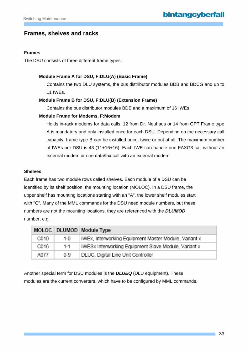
Switching Maintenance
Frames, shelves and racks Frames The DSU consists of three different frame types:
Module Frame A for DSU, F:DLU(A) (Basic Frame) Contains the two DLU systems, the bus distributor modules BDB and BDCG and up to
11 IWEs.
Module Frame B for DSU, F:DLU(B) (Extension Frame) Contains the bus distributor modules BDE and a maximum of 16 IWEs
Module Frame for Modems, F:Modem Holds in-rack modems for data calls. 12 from Dr. Neuhaus or 14 from GPT Frame type
A is mandatory and only installed once for each DSU. Depending on the necessary call
capacity, frame type B can be installed once, twice or not at all. The maximum number
of IWEs per DSU is 43 (11+16+16). Each IWE can handle one FAXG3 call without an
external modem or one data/fax call with an external modem.
Shelves Each frame has two module rows called shelves. Each module of a DSU can be
identified by its shelf position, the mounting location (MOLOC). In a DSU frame, the
upper shelf has mounting locations starting with an "A", the lower shelf modules start
with "C". Many of the MML commands for the DSU need module numbers, but these
numbers are not the mounting locations, they are referenced with the DLUMOD
number, e.g.
Another special term for DSU modules is the DLUEQ (DLU equipment). These
modules are the current converters, which have to be configured by MML commands.
33BCCN2200 © 2007 Bintang CyberFall
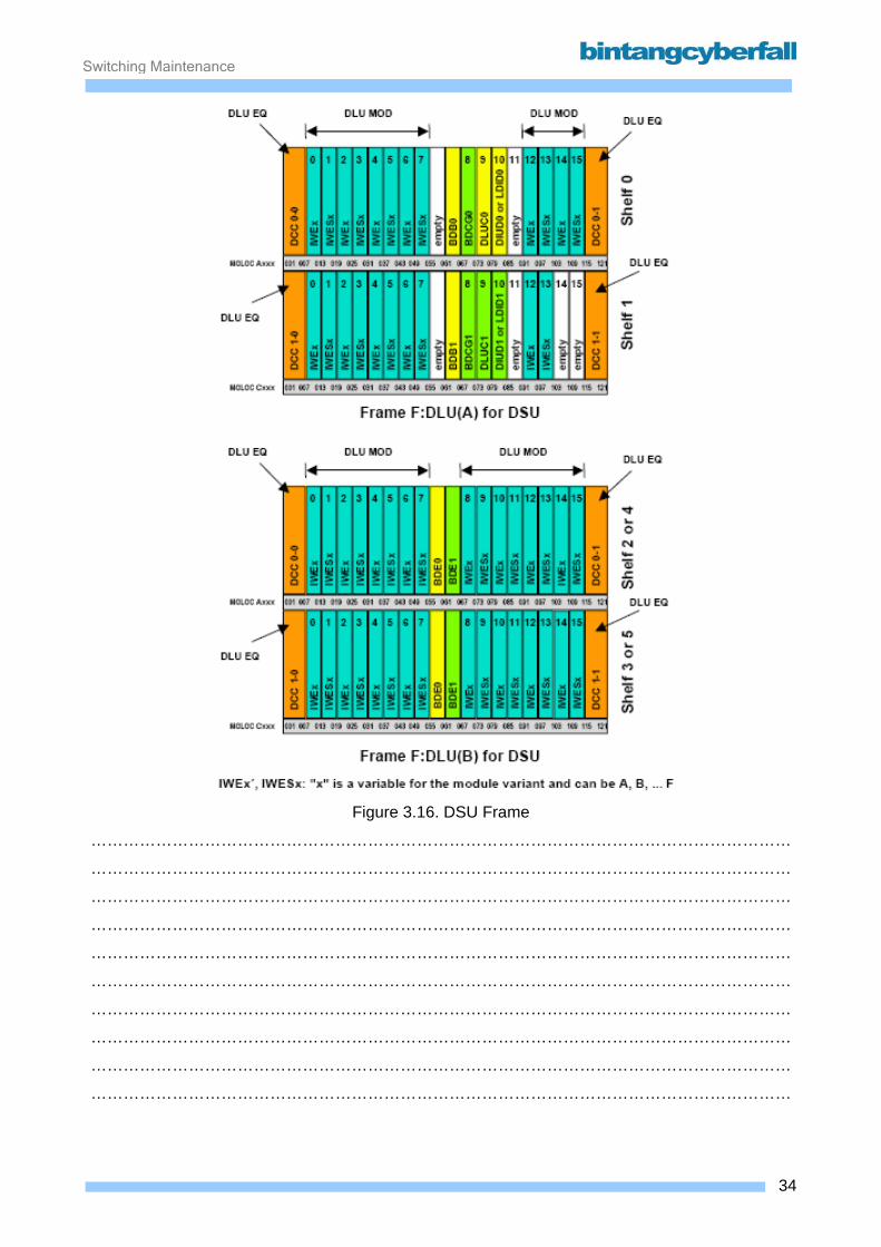
Switching Maintenance
Figure 3.16. DSU Frame
…………………………………………………………………………………………………………………
…………………………………………………………………………………………………………………
…………………………………………………………………………………………………………………
…………………………………………………………………………………………………………………
…………………………………………………………………………………………………………………
…………………………………………………………………………………………………………………
…………………………………………………………………………………………………………………
…………………………………………………………………………………………………………………
…………………………………………………………………………………………………………………
…………………………………………………………………………………………………………………
34BCCN2200 © 2007 Bintang CyberFall
Switching Maintenance
Racks The rack for the DSU (R:DSU) holds one DLU(A) frame and up to two DLU(B) frames.
Additionally, two modem frames can be installed. If necessary, additional modems can be installed
in another rack (R:Modem).
Every frame has a number, the mounting unit (MUT). Located on the top of each rack is the fuse
panel, which has a MUT number, too. The numbers start with 1 for the fuse panel, 2 for the
DLU(A) frame and so on.
There is a gap after the frame in mounting unit 3, the next frame counts as MUT 5! The MUT
numbers are printed on a label on the frame.
35BCCN2200 © 2007 Bintang CyberFall
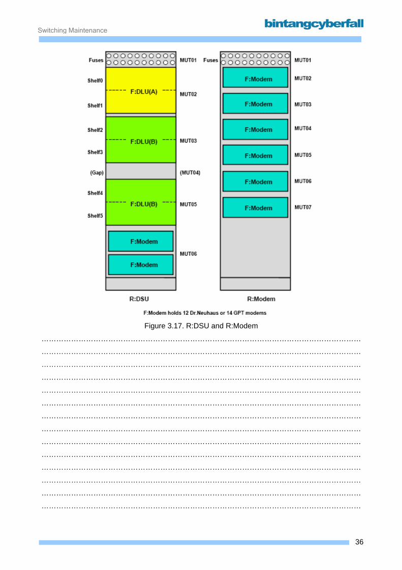
Switching Maintenance
Figure 3.17. R:DSU and R:Modem
…………………………………………………………………………………………………………………
…………………………………………………………………………………………………………………
…………………………………………………………………………………………………………………
…………………………………………………………………………………………………………………
…………………………………………………………………………………………………………………
…………………………………………………………………………………………………………………
…………………………………………………………………………………………………………………
…………………………………………………………………………………………………………………
…………………………………………………………………………………………………………………
…………………………………………………………………………………………………………………
…………………………………………………………………………………………………………………
…………………………………………………………………………………………………………………
…………………………………………………………………………………………………………………
…………………………………………………………………………………………………………………
36BCCN2200 © 2007 Bintang CyberFall
Switching Maintenance
4. Switching Subsystem – Switching Function
Contents 4.1. Switching Network ..................................................................................................................... 2
4.1. 1. Function ............................................................................................................................. 3 4.1.2. Hardware and Location ....................................................................................................... 5
1BCCN2200 © 2007 Bintang CyberFall

Switching Maintenance
4.1. Switching Network
2BCCN2200 © 2007 Bintang CyberFall
Switching Maintenance
4.1. 1. Function
The switching network SN is the link inside a node for:
• traffic connections between LTGs (temporary through connections)
• the D900 internal message exchange between LTG, SSNC and CP control units via fixed
message channels MCH
• CCS7 signaling messages between CCS7 signaling channels in PCM links connected to
the LTG and the SSNC (fixed connections set by command).
The switching network is fully duplicated (SN0 and SN1). For traffic connections, one is the active,
the other one the standby side. All calls are always simultaneously through connected via both SN
sides while the LTG only through connects user channel information received from the active SN
to the PCM links. If the active SN fails the system switches to the standby SN without any loss.
Through connection in the SN occurs in accordance with the "time – space – time" principle
(change of time slot – change of space slot – change of time slot). Each through connection
ensures a transparent bi-directional 64kbit/s path through the SN.
In addition to temporary through connections (transient calls), the following nonswitched
connections also apply:
• nailed-up connections (NUC) set by MML command
• through connection of message channels between LTG control units and the message buffer
(permanently specified by CP software).
Most connections between the SN and other functional units use secondary digital carrier lines
(SDC) with a bit rate of 8192kbps (mostly called 8Mbit system or highways), carrying 128 standard
64kbps time slots (numbers 0-127).
When using the LTG-P, the SDC:LTG of 16 LTGPs each may be realized as fiber optics with a
transmission rate of 184 Mb/s using one module SNOPT to connect the F:LTGP to SNMUXB.
3BCCN2200 © 2007 Bintang CyberFall
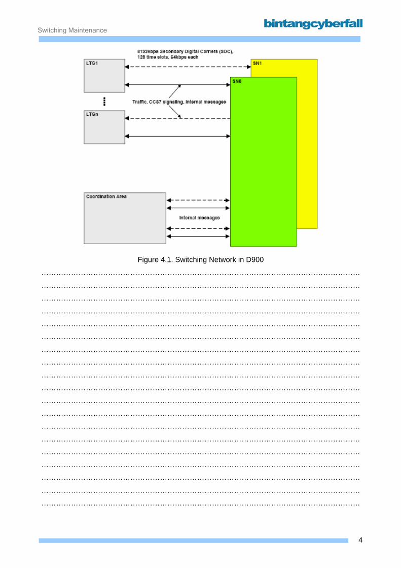
Switching Maintenance
Figure 4.1. Switching Network in D900
…………………………………………………………………………………………………………………
…………………………………………………………………………………………………………………
…………………………………………………………………………………………………………………
…………………………………………………………………………………………………………………
…………………………………………………………………………………………………………………
…………………………………………………………………………………………………………………
…………………………………………………………………………………………………………………
…………………………………………………………………………………………………………………
…………………………………………………………………………………………………………………
…………………………………………………………………………………………………………………
…………………………………………………………………………………………………………………
…………………………………………………………………………………………………………………
…………………………………………………………………………………………………………………
…………………………………………………………………………………………………………………
…………………………………………………………………………………………………………………
…………………………………………………………………………………………………………………
…………………………………………………………………………………………………………………
…………………………………………………………………………………………………………………
…………………………………………………………………………………………………………………
4BCCN2200 © 2007 Bintang CyberFall

Switching Maintenance
4.1.2. Hardware and Location
SN(B) The SN(B) for D900 systems is available in different capacity stages. With the exception of the
small switching network for a maximum of 63 LTGs (combined space-time stages), each SN
consists of the subunits time stage group (TSG) and space stage group (SSG).
Time Stage Group (TSG): Each TSG connects the SDC to/from the LTG and MB. 64 of this SDCs can be connected to each
TSG. An SN is made of a maximum of 8 duplicated TSG. Each TSG contains a switch group
control (SGC) which is connected to the CP via the message buffer (MB) with an own SDC line.
The SGC receives setting instructions for temporary or fixed bi-directional 64kbps through
connections from the CP. The SGC implements through connections by setting the individual time
stage modules (TSM) in a TSG. Inside a TSG each TSM can change the position in time and
space of any time slot arbitrarily for a group of 8 connected SDC.
Space Stage Group (SSG): The SSG through connects a call between TSM inside the same or different TSG. An SN consists
of a maximum of 4 duplicated SSG. Inside the SSG is a switch group control (SGC) connected to
the CP via the message buffer (MB). The SGC receives setting instructions for temporary or fixed
bi-directional 64kbps through connections from the CP. The SGC implements through connections
by setting the individual space stage modules (SSM) in an SSG. Each SSM can change the space
slot of the time slot for connected SDC arbitrarily.
External and internal connections The following types of secondary digital carriers (SDC) with 8Mbps form the internal and external
interfaces of the SN:
• SDC:LTG between TSG and maximum 63 LTG for circuit connections (time slots 1-127)
and for message exchange between the LTG GP control unit and the CP (message
channel to time slot 0). Any TSG port can be used except 0, which is reserved for the
SDC:TSG to the message buffer.
• one SDC:TSG between TSG and MB to transfer the message channel for all LTG in this
TSG to the CP. Always connected to port 0 of every TSG.
5BCCN2200 © 2007 Bintang CyberFall
Switching Maintenance
• one SDC:SGC between the SGC control unit in a TSG/SSG and the MB to transfer the
CP setting instructions to TSG/SSG
• The individual TSG and SSG are connected to each other via SDC:SSG
6BCCN2200 © 2007 Bintang CyberFall
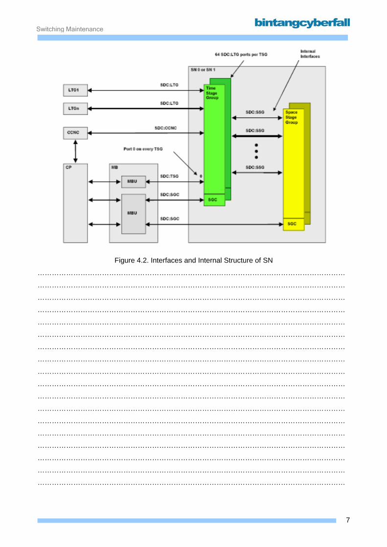
Switching Maintenance
Figure 4.2. Interfaces and Internal Structure of SN
…………………………………………………………………………………………………………………
…………………………………………………………………………………………………………………
…………………………………………………………………………………………………………………
…………………………………………………………………………………………………………………
…………………………………………………………………………………………………………………
…………………………………………………………………………………………………………………
…………………………………………………………………………………………………………………
…………………………………………………………………………………………………………………
…………………………………………………………………………………………………………………
…………………………………………………………………………………………………………………
…………………………………………………………………………………………………………………
…………………………………………………………………………………………………………………
…………………………………………………………………………………………………………………
…………………………………………………………………………………………………………………
…………………………………………………………………………………………………………………
…………………………………………………………………………………………………………………
…………………………………………………………………………………………………………………
…………………………………………………………………………………………………………………
7BCCN2200 © 2007 Bintang CyberFall
Switching Maintenance
Capacity stages As the SN is available in different increments the actual size of the switching network can be
matched to the expected traffic volume in an exchange. The volume of traffic to be through
connected measured in Erlangs is used as the dimensional size.
In addition to the increments listed the special implementation of SN for 31 LTG and for 63 LTG is
also available for small D900.
Capacity / space requirements for SN increments: • If a CCNC is connected, 1 or 2 SDC:CCNC are added depending on the number of CCS7
signaling channels; the number of SDC:LTG is reduced accordingly.
• Space requirements inside a rack:
Each TSG requires only one frame inside a rack. Each SSG requires only a half of a frame
inside a rack. The remaining space inside the rack can be used for LTG.
In a TSG rack it is possible to install a maximum of 4 LTG module frames.
In an SSG rack it is possible to install a maximum of 4 LTG module frames.
In the SN:63LTG rack it is possible to install a maximum of 4 LTG module frames.
The SN:31LTG is stored inside the CP rack.
Mobile systems are not fully equipped with all possible LTGs. Because of the much higher
signaling load in a PLMN, the amount of internal messages would be too high for the message
buffer. Figure below shows the capacity stages of D900 and D900 systems.
8BCCN2200 © 2007 Bintang CyberFall
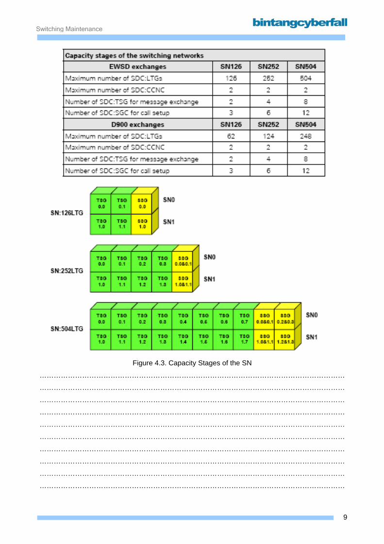
Switching Maintenance
Figure 4.3. Capacity Stages of the SN
…………………………………………………………………………………………………………………
…………………………………………………………………………………………………………………
…………………………………………………………………………………………………………………
…………………………………………………………………………………………………………………
…………………………………………………………………………………………………………………
…………………………………………………………………………………………………………………
…………………………………………………………………………………………………………………
…………………………………………………………………………………………………………………
…………………………………………………………………………………………………………………
…………………………………………………………………………………………………………………
9BCCN2200 © 2007 Bintang CyberFall

Switching Maintenance
SN(B) functional units and modules The SN(B) is divided into the following functional units:
• Time switch circuit (TSC)
A TSC can connect each incoming time slot belonging to one of the 4 connected SDC:LTG to a
random outgoing time slot on any of the 4 connected SN internal SDCs. As each of the SDCs is
always bi-directional a TSC is divided into TSC incoming and TSC outgoing.
• Link interface to LTG (LIL)
The LIL is the interface to the LTG. It is responsible for propagation time equalization of the
SDC:LTG.
• Space switch SS16|16
An SS16|16 can connect any incoming time slot belonging to one of the 16 connected SDC to
the outgoing time slot with the same number belonging to any of these 16 SDC.
• Space Switch SS8|15
An SS8|15 is connected to 8 SDC on one side and 15 SDC on the other side.
Each SS8|15 is divided into two subunits. One unit can connect any incoming time slot belonging
to one of the 8 SDC on one side to the outgoing time slot with the same number belonging to
one of the 15 SDC on the other side. The other subunit can connect any incoming time slot
belonging to one of the 15 SDC on one side to the outgoing time slot with the same number
belonging to one of the 8 SDC on the other side.
• Link interface between TSG and SSG (LIS)
The SDC:SSG (TSG – SSG) are connected to SSG and TSG via the LIS. These act as
interfaces for propagation time equalization of the individual SDC. In addition the LIS specifies
which TSG (SN0 or 1) will interoperate with which SSG (SN0 or 1). In this sense it can be
compared to the LIU function inside the LTG.
• Switch group control (SGC)
Each SGC controls the functional units in its TSG/SSG. To do this it interacts with the CP via its
SDC:SGC.
10BCCN2200 © 2007 Bintang CyberFall

Switching Maintenance
• Link Interface to message buffer (LIM)
The interface function for the SDC:SGC to the message buffer is implemented by means of the
LIM component.
In the SN(B) the individual functional units are assigned to modules as follows:
• 2 TSC including LIL function are implemented in one TSMB module
• in the TSG the LIS function for 16 SDC is implemented in one LISB module
• the LIS function of the SSG is implemented with 2 SS8|15 in one SSM8B module
• 8 SS16|16 are implemented in one SSM16B module
• LIM and SGC functions are implemented in one SGCB
11BCCN2200 © 2007 Bintang CyberFall

Switching Maintenance
Figure 4.4. Internal Structure of TSG and SSG
…………………………………………………………………………………………………………………
…………………………………………………………………………………………………………………
…………………………………………………………………………………………………………………
…………………………………………………………………………………………………………………
…………………………………………………………………………………………………………………
…………………………………………………………………………………………………………………
…………………………………………………………………………………………………………………
…………………………………………………………………………………………………………………
…………………………………………………………………………………………………………………
…………………………………………………………………………………………………………………
…………………………………………………………………………………………………………………
…………………………………………………………………………………………………………………
…………………………………………………………………………………………………………………
…………………………………………………………………………………………………………………
…………………………………………………………………………………………………………………
…………………………………………………………………………………………………………………
…………………………………………………………………………………………………………………
…………………………………………………………………………………………………………………
…………………………………………………………………………………………………………………
…………………………………………………………………………………………………………………
…………………………………………………………………………………………………………………
…………………………………………………………………………………………………………………
12BCCN2200 © 2007 Bintang CyberFall

Switching Maintenance
SN(B) rack and module frames
Each SN rack always contains 2 SN module frames. These can be installed inside
the rack at the top or bottom. The remaining space inside the rack can be used for
LTG and/or MB.
A rack always contains one of the following module frame types for redundant units
from SN0 and SN1:
• TSG(B) frame with one TSG
• SSG(B) frame with one or two SSG belonging to the same SN plane
• TSG(B) frame with one SN:63LTG plane
13BCCN2200 © 2007 Bintang CyberFall

Switching Maintenance
Figure 4.5. Frame for SN(B)
…………………………………………………………………………………………………………………
…………………………………………………………………………………………………………………
…………………………………………………………………………………………………………………
…………………………………………………………………………………………………………………
…………………………………………………………………………………………………………………
…………………………………………………………………………………………………………………
…………………………………………………………………………………………………………………
…………………………………………………………………………………………………………………
…………………………………………………………………………………………………………………
…………………………………………………………………………………………………………………
…………………………………………………………………………………………………………………
…………………………………………………………………………………………………………………
…………………………………………………………………………………………………………………
…………………………………………………………………………………………………………………
…………………………………………………………………………………………………………………
…………………………………………………………………………………………………………………
…………………………………………………………………………………………………………………
14BCCN2200 © 2007 Bintang CyberFall
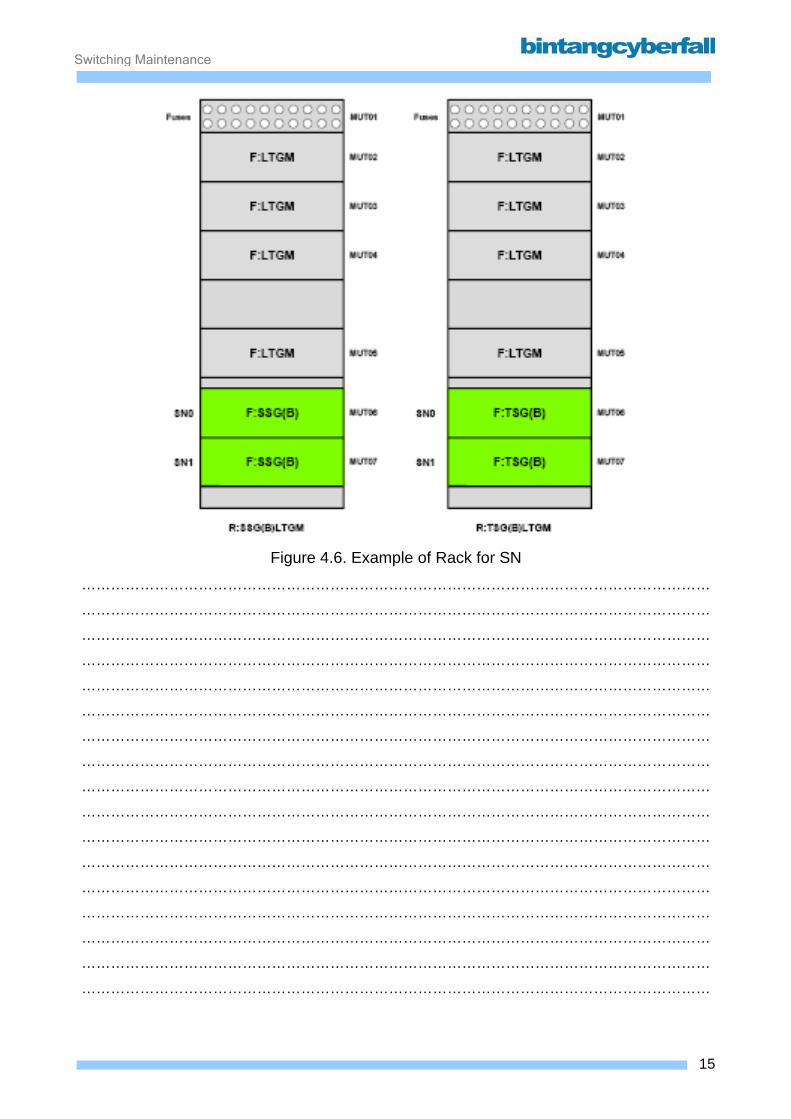
Switching Maintenance
Figure 4.6. Example of Rack for SN
…………………………………………………………………………………………………………………
…………………………………………………………………………………………………………………
…………………………………………………………………………………………………………………
…………………………………………………………………………………………………………………
…………………………………………………………………………………………………………………
…………………………………………………………………………………………………………………
…………………………………………………………………………………………………………………
…………………………………………………………………………………………………………………
…………………………………………………………………………………………………………………
…………………………………………………………………………………………………………………
…………………………………………………………………………………………………………………
…………………………………………………………………………………………………………………
…………………………………………………………………………………………………………………
…………………………………………………………………………………………………………………
…………………………………………………………………………………………………………………
…………………………………………………………………………………………………………………
…………………………………………………………………………………………………………………
15BCCN2200 © 2007 Bintang CyberFall
Switching Maintenance
SND With SND, a new type of switching network is offered for D900/1800/1900. It adopts and expands
upon the functions of the SN B:
• Connection of up to 1008 LTGs (planned for 2016 LTGs, but only 1008 realized in
SR10)
• Non-blocking design (every path can be used at any time independently of the other
paths)
• Compatible to all LTG types
• Permanent supervision of the traffic channel paths via parity bits
• Suitable for use in both small as well as large exchanges with small growth gradation
(16 LTG)
The SND is designed redundantly for security reasons (SND0 and SND1). Each connection is
always switched over both SND sides at the same time. If one SND side fails, the redundant
switching of connections through the two SND sides ensures that no call data are lost and that the
SND retains all of its functionality. The LTGs send to both SN sides but when receiving from the
SN, only the channels arriving from the active SN side are forwarded.
In addition to the transient user channel connections, the following fixed connections can be
switched:
• Long-term connections ("nailed-up connections", NUC) are activated by means of
an MML command,
• Message channels between LTG control units and the message buffer (specified by
the CP software as long-term connections).
All connections between the SN and the directly connected functional units MBD and LTG are
made via secondary digital carriers SDC at a bit rate of 8192 kbps, each with 128 standard time
slots at 64 kbps (numbers 1-127). (The SDC are generally referred to as 8Mbit systems or
"highways")
• The SDC:LTG between the SN D and the LTGs includes user channel connections
/ permanently connected SS7 links (time slots 0-127) as well as the LTG message
channel (MCH in time slot 0)
• An SDC between SN D and MB D is used to forward the communication paths of
65 LTGs each to the MBD.
16BCCN2200 © 2007 Bintang CyberFall
Switching Maintenance
• SDCs of the type MBD-S1 and MBD-S3 are used to transmit the CP setting
commands (via MB D) to the SND.
When using the LTG-P, the SDC:LTG of 16 LTGPs each may be realized as fiber optics with a
transmission rate of 184 Mb/s using one module SNOPT to connect the F:LTGP to SNMUXB.
17BCCN2200 © 2007 Bintang CyberFall
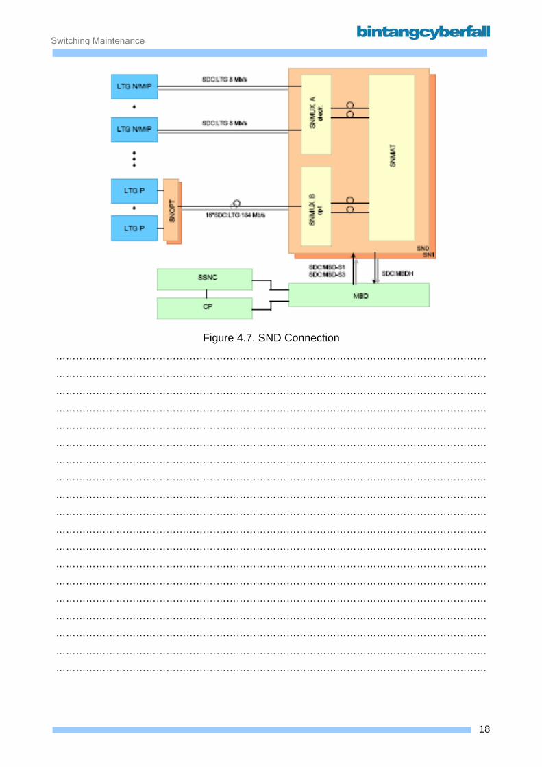
Switching Maintenance
Figure 4.7. SND Connection
…………………………………………………………………………………………………………………
…………………………………………………………………………………………………………………
…………………………………………………………………………………………………………………
…………………………………………………………………………………………………………………
…………………………………………………………………………………………………………………
…………………………………………………………………………………………………………………
…………………………………………………………………………………………………………………
…………………………………………………………………………………………………………………
…………………………………………………………………………………………………………………
…………………………………………………………………………………………………………………
…………………………………………………………………………………………………………………
…………………………………………………………………………………………………………………
…………………………………………………………………………………………………………………
…………………………………………………………………………………………………………………
…………………………………………………………………………………………………………………
…………………………………………………………………………………………………………………
…………………………………………………………………………………………………………………
…………………………………………………………………………………………………………………
…………………………………………………………………………………………………………………
18BCCN2200 © 2007 Bintang CyberFall

Switching Maintenance
Capacity stages Thanks to its modular design, an operational SND can be extended on site beyond the limits of the
originally configured capacity stage if it has to be expanded to accommodate planning changes.
The different capacity stages of the SND are realized by the number of switching network
multiplexers (SNMUX) used.
SND for up to 126 LTG Only one switching network multiplexer is needed for an SND for up to 126 LTGs. In this
configuration, the SNMUX has a switching function.
SND for up to 252 LTG Two switching network multiplexers (SNMUX1 and SNMUX2) are used in the case of an SND for
up to a maximum of 252 LTGs. In this constellation, the SNMUX1 implements the switching
function and the SNMUX2 the multiplexer/demultiplexer function. Both SNMUX are directly
connected with each other by optical waveguides at 920 Mbit/s in this capacity stage.
SND for up to 1008 LTG Additional switching network multiplexers (up to a maximum of 8 SNMUX) and a switching network
matrix (SNMAT) are used in capacity stages for more than 252 LTGs (up to maximum 1008
LTGs). All SNMUX are connected directly with the SNMAT using 920-Mbit/s optical waveguides. In
this case the SNMUX implements the multiplexer function and the SNMAT the switching function.
19BCCN2200 © 2007 Bintang CyberFall
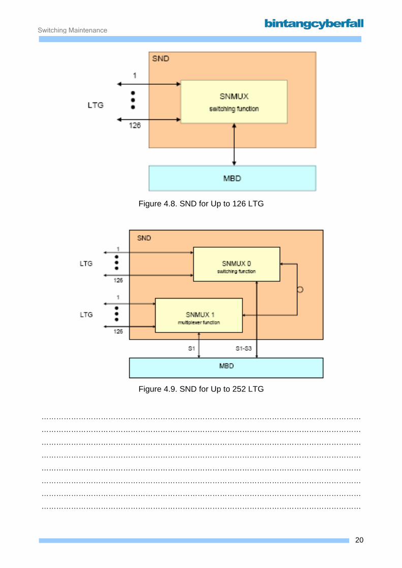
Switching Maintenance
Figure 4.8. SND for Up to 126 LTG
Figure 4.9. SND for Up to 252 LTG
…………………………………………………………………………………………………………………
…………………………………………………………………………………………………………………
…………………………………………………………………………………………………………………
…………………………………………………………………………………………………………………
…………………………………………………………………………………………………………………
…………………………………………………………………………………………………………………
…………………………………………………………………………………………………………………
…………………………………………………………………………………………………………………
20BCCN2200 © 2007 Bintang CyberFall
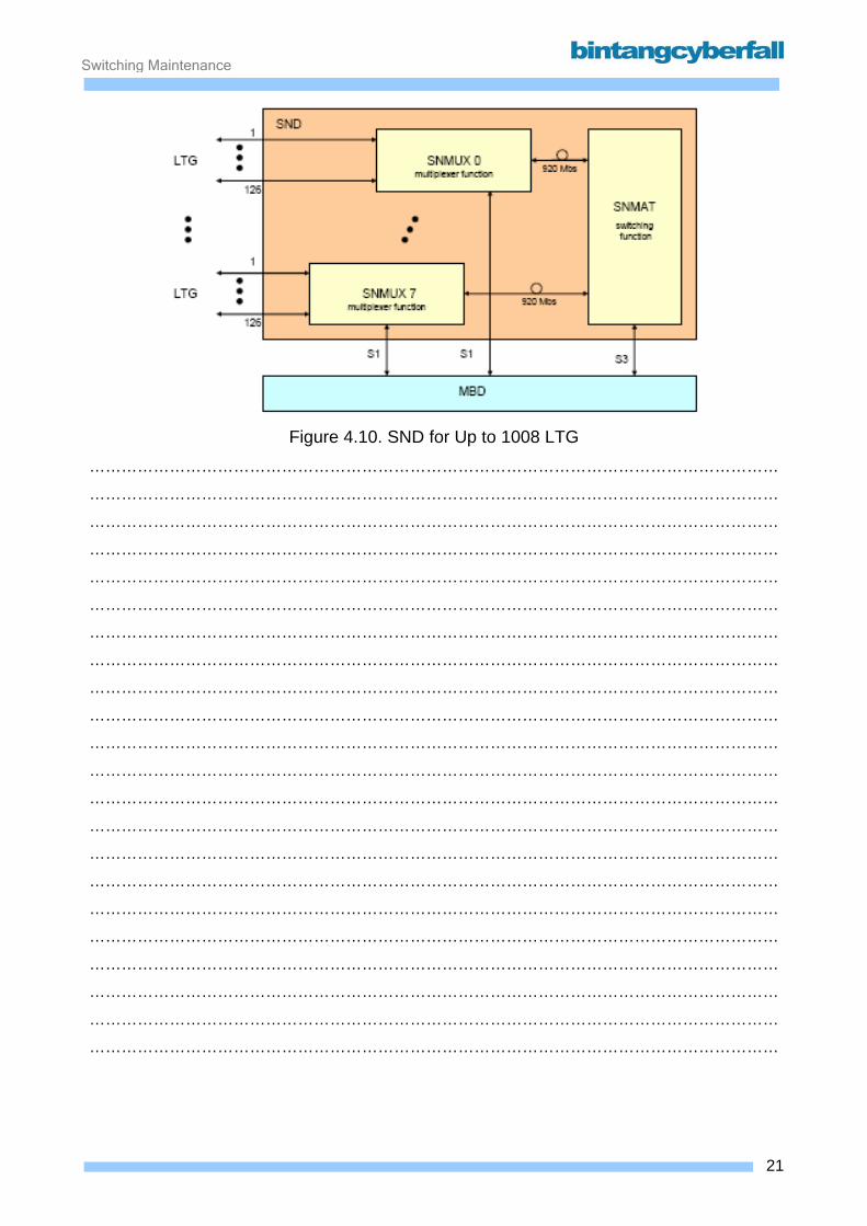
Switching Maintenance
Figure 4.10. SND for Up to 1008 LTG
…………………………………………………………………………………………………………………
…………………………………………………………………………………………………………………
…………………………………………………………………………………………………………………
…………………………………………………………………………………………………………………
…………………………………………………………………………………………………………………
…………………………………………………………………………………………………………………
…………………………………………………………………………………………………………………
…………………………………………………………………………………………………………………
…………………………………………………………………………………………………………………
…………………………………………………………………………………………………………………
…………………………………………………………………………………………………………………
…………………………………………………………………………………………………………………
…………………………………………………………………………………………………………………
…………………………………………………………………………………………………………………
…………………………………………………………………………………………………………………
…………………………………………………………………………………………………………………
…………………………………………………………………………………………………………………
…………………………………………………………………………………………………………………
…………………………………………………………………………………………………………………
…………………………………………………………………………………………………………………
…………………………………………………………………………………………………………………
…………………………………………………………………………………………………………………
21BCCN2200 © 2007 Bintang CyberFall
Switching Maintenance
SND hardware layout The following diagrams illustrate only the major functional units of the SND modules.
The interfaces are greatly simplified and the redundancy of the SND is not shown.
Switching Network Multiplexer (SNMUXA) The switching network multiplexer (SNMUXA) comprises the following:
• interface module type D for LTG, (LILD)
• multiplexer controller module (MUXC)
• transceiver module for optical connections (OML920).
The LILD and MUXC together comprise the multiplexer/demultiplexer for the connection to the
LTGs. Depending on the capacity stage of the SND, the MUXC can also perform switching
functions.
The interfaces to the SNMAT are implemented using OML920 as optical links. Up to 2 OML920s
can be plugged into the rear of the module frame for each SNMUXA. A maximum of 16 OML920s
are possible for a maximum configuration of 8 SNMUXAs. The optical connections are bi-
directional lines. Data are transmitted at 920 Mbit/s in each direction.
Switching Network Multiplexer (SNMUXB) The switching network multiplexer (SNMUXB) comprises the following:
• optical fiber connectors (M:OFC)
• interface module type E for LTG, (LILE)
• multiplexer controller module (MUXC)
• transceiver module for optical connections (OML920).
The OFC form the optical interface to the F:LTGP at 184 Mbit/s. The LILD and MUXC together
comprise the multiplexer/demultiplexer for the connection to the LTGs.
MUXC and OML920 have the same function as in SNMUXA.
Switching Network Matrix (SNMAT) The switching network matrix (SNMAT, Fig. 3.6) comprises the following:
• matrix modules (MATM)
• matrix controller module (MATC)
• transceiver module for optical connections (OML920).
22BCCN2200 © 2007 Bintang CyberFall
Switching Maintenance
Each matrix module (MATM) is assigned four transmit and receive modules (OML920). These
each convert the serial optical data streams fed from the switching network multiplexer (SNMUXA)
into four 184 Mbit/s data signals. Each of these four signals is then split into eight output signals
and routed to each of the eight MATMs.
The blocking-free switching network matrix structure obtained in this way is controlled, supervised
and clocked in the SNMAT by the MATC and MATM.
The SNMAT is connected with the MBD (MBDH) via an 8-Mbit/s HDLC interface (to the MATC
module).
23BCCN2200 © 2007 Bintang CyberFall

Switching Maintenance
Figure 4.11. SND Functional Units
…………………………………………………………………………………………………………………
…………………………………………………………………………………………………………………
…………………………………………………………………………………………………………………
…………………………………………………………………………………………………………………
…………………………………………………………………………………………………………………
…………………………………………………………………………………………………………………
…………………………………………………………………………………………………………………
…………………………………………………………………………………………………………………
…………………………………………………………………………………………………………………
…………………………………………………………………………………………………………………
…………………………………………………………………………………………………………………
…………………………………………………………………………………………………………………
…………………………………………………………………………………………………………………
…………………………………………………………………………………………………………………
…………………………………………………………………………………………………………………
…………………………………………………………………………………………………………………
…………………………………………………………………………………………………………………
…………………………………………………………………………………………………………………
…………………………………………………………………………………………………………………
…………………………………………………………………………………………………………………
24BCCN2200 © 2007 Bintang CyberFall
Switching Maintenance
Frames of SND F:SNMUXA comprises the following modules:
• M:LILD: LTG Switching Interface Module Type D
M:LILD forms the interface to LTG and MBDH (LTG - MCH interface). To do so, 16 8-
Mbit/s SDC inputs from the LTGs are combined into one high-speed ATM connection at
184.32 Mbit/s. To these 16 * 128 user channels (payload) another 256 test and
synchronization channels are added. Within the SND, all 8-bit time slots are monitored by
means of 2 parity bits.
• M:MUXC: Multiplex Control Module
M:MUXC controls the eight M:LILD and the two M:OML920 via 2 Mbit/s HDLC connections.
Depending on the configuration of the SND, the MUXC can be used as a "switch" (SND for
up to 252 LTG) or as a pure "multiplexer" (SND for more than 252 LTGs and thus with
SNMAT).
The M:MUXC receives/sends the 184.32 Mbit/s highway data from/to the M:LILD modules.
In an SND for up to 252 LTG, the MUXC module is additionally connected via M:OML920
to the MUXC of the other SNMUX.
In an SND for more than 252 LTG, each MUXC module is connected via two M:OML920 to
the SNMAT.
• M:OML920: Optical Multiplexer Switching Module for Serial Data Rates of 920 Mbit/s
In SND with more than 126 LTG, the OML920 enables data transmission via fiber optic
cables between the frames. The OML920 is a transceiver module on the rear panel of the
module frame, transparent to the transmitted data.
Four electrical data streams, each at 184.32 Mbit/s are united and sent from one OML920
module to other OML920 modules via fiber optic cables. This bidirectional data connection
can be used over a distance of up to 200 m.
For technical reasons, the bit rate increases by a ratio of 5/4 compared with 4*184Mbps.
25BCCN2200 © 2007 Bintang CyberFall
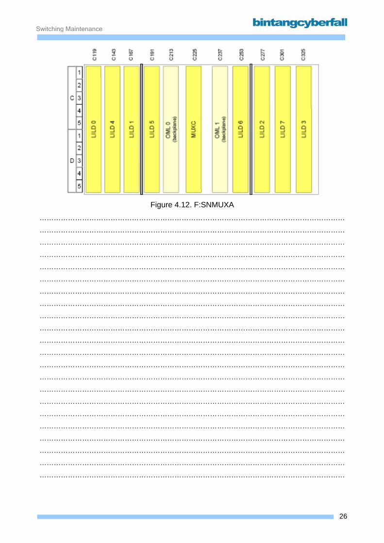
Switching Maintenance
Figure 4.12. F:SNMUXA
…………………………………………………………………………………………………………………
…………………………………………………………………………………………………………………
…………………………………………………………………………………………………………………
…………………………………………………………………………………………………………………
…………………………………………………………………………………………………………………
…………………………………………………………………………………………………………………
…………………………………………………………………………………………………………………
…………………………………………………………………………………………………………………
…………………………………………………………………………………………………………………
…………………………………………………………………………………………………………………
…………………………………………………………………………………………………………………
…………………………………………………………………………………………………………………
…………………………………………………………………………………………………………………
…………………………………………………………………………………………………………………
…………………………………………………………………………………………………………………
…………………………………………………………………………………………………………………
…………………………………………………………………………………………………………………
…………………………………………………………………………………………………………………
…………………………………………………………………………………………………………………
…………………………………………………………………………………………………………………
…………………………………………………………………………………………………………………
…………………………………………………………………………………………………………………
26BCCN2200 © 2007 Bintang CyberFall
Switching Maintenance
F:SNMUXB comprises the following modules:
• M:OFC: Optical Fiber Connector
M:OFC is the counterpart of M:SNOPT and transforms the optical 184 Mbit/s signals from
F:LTGP into electrical 184Mbit/s signals for the M:LILE.
• M:LILE: LTG Switching Interface Module Type E
The M:LILE forms the interface to the new environment LTGP. It receives the data from/to
MBUL0-0, MBUL 0-1, and up to 15 LTGs as electrical 8,192 Mbit/s interfaces. For LTG 1-
15 an optical interface is provided as well but if the electrical interfaces are plugged they
overwrite the optical interfaces. Additionally 8 bidirectional optical interfaces (184.32
Mbit/s), each holding 16x 8,192 Mbit/s SDCs links are provided. It performs an alignment
by equalizing clock and cable length
differences and multiplexes them to the internal 184.32 Mbit/s links. Furthermore 2 parity
bits for each time slot and an additional maintenance overhead is inserted and evaluated.
• M:MUXC: Multiplex Control Module
Depending on the configuration of the SND, the MUXC can be used as a "switch" (SND for
up to 252 LTG) or as a pure "multiplexer" (SND for more than 252 LTGs and thus with
SNMAT). The M:MUXC receives/sends the 184.32 Mbit/s highway data from/to the M:LILD
modules. In an SND for up to 252 LTG, the MUXC module is additionally connected via
M:OML920 to the MUXC of the other SNMUX. In an SND for more than 252 LTG, each
MUXC module is connected via two M:OML920 to the SNMAT.
• M:OML920: Optical Multiplexer Switching Module for Serial Data Rates of 920 Mbit/s
In SND with more than 126 LTG, the OML920 enables data transmission via fiber optic
cables between the frames. The OML920 is a transceiver module on the rear panel of the
module frame, transparent to the transmitted data. Four electrical data streams, each at
184.32 Mbit/s are united and sent from one OML920 module to other OML920 modules
via fiber optic cables. This bi-directional data connection can be used over a distance of up
to 200 m. For technical reasons, the bit rate increases by a ratio of 5/4 compared with
4*184Mbps.
• M:SNOPT: Optical Interface to SN
The module M:SNOPT provides optoelectrical signal conversion and a MUX/DEMUX
to/from the SDC signals to the different M:GGPPs. Although it is located at the backplane
of F:LTGP, it belongs to the SND and is controlled via M:LILE.
27BCCN2200 © 2007 Bintang CyberFall
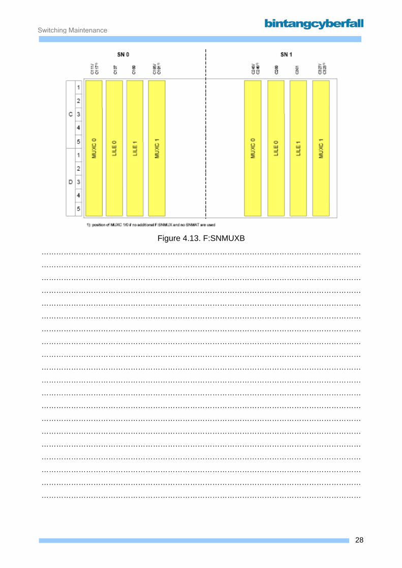
Switching Maintenance
Figure 4.13. F:SNMUXB
…………………………………………………………………………………………………………………
…………………………………………………………………………………………………………………
…………………………………………………………………………………………………………………
………………………………………………………………………………………………………………… …………………………………………………………………………………………………………………
………………………………………………………………………………………………………………… …………………………………………………………………………………………………………………
………………………………………………………………………………………………………………… …………………………………………………………………………………………………………………
………………………………………………………………………………………………………………… …………………………………………………………………………………………………………………
………………………………………………………………………………………………………………… …………………………………………………………………………………………………………………
………………………………………………………………………………………………………………… …………………………………………………………………………………………………………………
………………………………………………………………………………………………………………… …………………………………………………………………………………………………………………
………………………………………………………………………………………………………………… …………………………………………………………………………………………………………………
…………………………………………………………………………………………………………………
28BCCN2200 © 2007 Bintang CyberFall
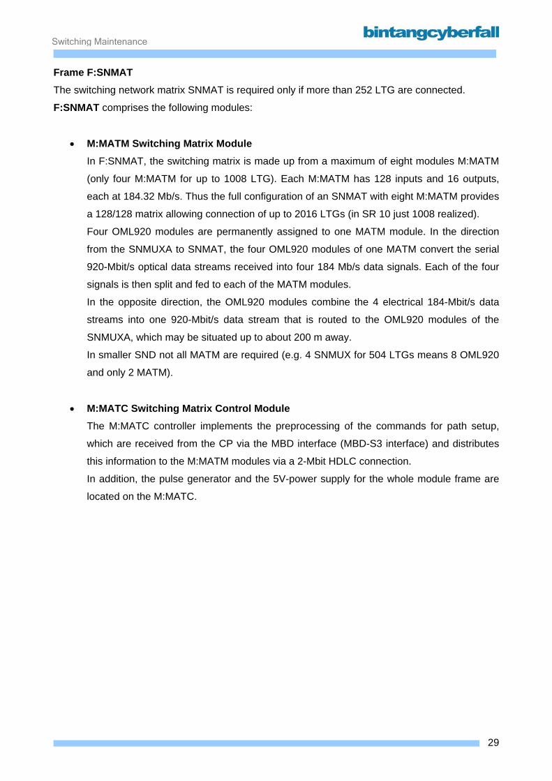
Switching Maintenance
Frame F:SNMAT The switching network matrix SNMAT is required only if more than 252 LTG are connected.
F:SNMAT comprises the following modules:
• M:MATM Switching Matrix Module In F:SNMAT, the switching matrix is made up from a maximum of eight modules M:MATM
(only four M:MATM for up to 1008 LTG). Each M:MATM has 128 inputs and 16 outputs,
each at 184.32 Mb/s. Thus the full configuration of an SNMAT with eight M:MATM provides
a 128/128 matrix allowing connection of up to 2016 LTGs (in SR 10 just 1008 realized).
Four OML920 modules are permanently assigned to one MATM module. In the direction
from the SNMUXA to SNMAT, the four OML920 modules of one MATM convert the serial
920-Mbit/s optical data streams received into four 184 Mb/s data signals. Each of the four
signals is then split and fed to each of the MATM modules.
In the opposite direction, the OML920 modules combine the 4 electrical 184-Mbit/s data
streams into one 920-Mbit/s data stream that is routed to the OML920 modules of the
SNMUXA, which may be situated up to about 200 m away.
In smaller SND not all MATM are required (e.g. 4 SNMUX for 504 LTGs means 8 OML920
and only 2 MATM).
• M:MATC Switching Matrix Control Module The M:MATC controller implements the preprocessing of the commands for path setup,
which are received from the CP via the MBD interface (MBD-S3 interface) and distributes
this information to the M:MATM modules via a 2-Mbit HDLC connection.
In addition, the pulse generator and the 5V-power supply for the whole module frame are
located on the M:MATC.
29BCCN2200 © 2007 Bintang CyberFall
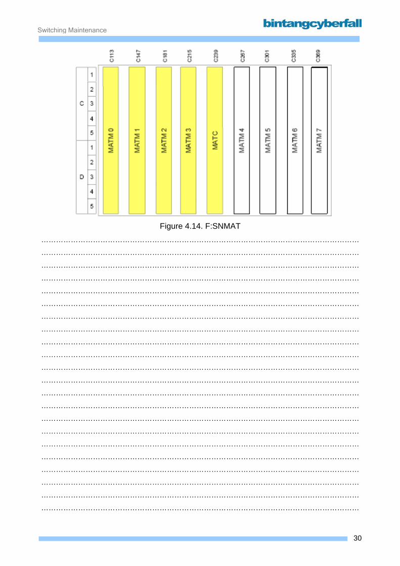
Switching Maintenance
Figure 4.14. F:SNMAT
…………………………………………………………………………………………………………………
…………………………………………………………………………………………………………………
…………………………………………………………………………………………………………………
…………………………………………………………………………………………………………………
…………………………………………………………………………………………………………………
…………………………………………………………………………………………………………………
…………………………………………………………………………………………………………………
…………………………………………………………………………………………………………………
…………………………………………………………………………………………………………………
…………………………………………………………………………………………………………………
…………………………………………………………………………………………………………………
…………………………………………………………………………………………………………………
…………………………………………………………………………………………………………………
…………………………………………………………………………………………………………………
…………………………………………………………………………………………………………………
…………………………………………………………………………………………………………………
…………………………………………………………………………………………………………………
…………………………………………………………………………………………………………………
…………………………………………………………………………………………………………………
…………………………………………………………………………………………………………………
…………………………………………………………………………………………………………………
…………………………………………………………………………………………………………………
30BCCN2200 © 2007 Bintang CyberFall
Switching Maintenance
5. Switching Subsystem – Coordination Function
Contents 5.1. Coordination Processor ............................................................................................................. 2
5.1. 1. Function ............................................................................................................................. 3 5.1.2. Hardware and Location ....................................................................................................... 4
5.2. Message Buffer........................................................................................................................ 33 5.2.1. Function ............................................................................................................................ 34 5.2.2. Hardware and Location ..................................................................................................... 36
5.3. Clock........................................................................................................................................ 45 5.3.1. Function ............................................................................................................................ 46 5.3.2. Hardware and Location ..................................................................................................... 48
5.4. Operation and Maintenance Console ...................................................................................... 54 5.4.1. Configuration and Interfaces ............................................................................................. 55 5.4.2. Function ............................................................................................................................ 58
5.5. Storages .................................................................................................................................. 60 5.5.1. Function ............................................................................................................................ 61 5.5.2. Hardware and Location ..................................................................................................... 62 5.5.3. Procedures........................................................................................................................ 67
1BCCN2200 © 2007 Bintang CyberFall

Switching Maintenance
5.1. Coordination Processor
2BCCN2200 © 2007 Bintang CyberFall
Switching Maintenance
5.1. 1. Function
The Coordination Processor is the heart of a the exchange. It controls all other functional units, does the main call processing tasks and processes MML inputs. The CP is divided into several subunits:
• two base processors (BAP) for maintenance and call processing tasks • two ATM Bridge Processors (AMP) as interface to the SSNC • up to 6 call processors (CAP) for call processing only • up to 4 input/output controllers as interfaces to input/output processors • a duplicated common memory (CMY) • a duplicated bus system (BCMY) between the BAPs, CAPs, IOCs and CMY • several input/output processors for connecting external equipment
The CP performs the following functions in a network node: Call processing
• digit translation • routing • zoning • path selection through the switching network • call charge registration • traffic data administration • network administration
Operation and maintenance
• input and output from/to external memories (EM) • communication with the operation and maintenance terminals (OMT /BCT) • communication with the operation and maintenance center (OMC)
Safeguarding • self-supervision • error detection • error handling
3BCCN2200 © 2007 Bintang CyberFall
Switching Maintenance
5.1.2. Hardware and Location
CP113C/CR The CP113C/CR comprises the following hardware functional units:
• base processors (BAP)
• ATM bridge processors (AMP)
• call processors (CAP)
• input/output controls (IOC)
• bus for common memory (BCMY)
• common memory (CMY)
• input/output processors (IOP):
o IOP:MB (input/output processor for message buffer)
o IOP:TA (input/output processor for time and alarms)
o IOP:LAU (input/output processor for line adaption unit)
o IOP:UNI (input/output processor unified for O&M devices)
o IOP:AUC (input/output processor for authentication center), only for use in mobile
communication network nodes (D900)
There are two BAPs in the CP113, one is called the master, performing all the maintenance tasks
and, if necessary, call processing. The other one is called spare, which does only call processing.
The master/slave status of the BAPs can be changed. Either manually with the MML command
COM BAP; or automatically by the system itself. This automatic change is normally done once a
day. If a BAP fails, his functionality will be replaced by the remaining BAP.
The optional call processors can not replace the functionality of the BAPs.
The basic configuration of the CP113C can be expanded as necessary by adding similar functional
units. This is true for computing and memory capacity, and also for the connection of call
processing plus operation and maintenance peripherals.
The operation and maintenance periphery (O&M periphery) and data communication periphery
can be expanded as required for the CP113C/CR. The following devices can be attached:
o magnetic disk device (MDD)
o magneto-optical disk device (MOD)
o operation and maintenance terminal (OMT or BCT)
4BCCN2200 © 2007 Bintang CyberFall
Switching Maintenance
o data links to data communication devices or to data terminal equipment with V.24, V.35,
V.36 interfaces and with the BX.25/X.25 protocol maintenance panel (used only by TAC
staff for special fault clearance procedures).
5BCCN2200 © 2007 Bintang CyberFall

Switching Maintenance
Figure 5.1. Hardware Structure of the CPCP113C/CR
…………………………………………………………………………………………………………………
…………………………………………………………………………………………………………………
…………………………………………………………………………………………………………………
…………………………………………………………………………………………………………………
…………………………………………………………………………………………………………………
…………………………………………………………………………………………………………………
…………………………………………………………………………………………………………………
…………………………………………………………………………………………………………………
…………………………………………………………………………………………………………………
…………………………………………………………………………………………………………………
…………………………………………………………………………………………………………………
…………………………………………………………………………………………………………………
…………………………………………………………………………………………………………………
…………………………………………………………………………………………………………………
…………………………………………………………………………………………………………………
…………………………………………………………………………………………………………………
…………………………………………………………………………………………………………………
…………………………………………………………………………………………………………………
…………………………………………………………………………………………………………………
…………………………………………………………………………………………………………………
6BCCN2200 © 2007 Bintang CyberFall
Switching Maintenance
BAP,CAP and IOC
The base processors, call processors and input/output controls are built using identical hardware
components and can therefore be described together.
Each processor comprises the following:
o two processing units (PU)
o a local memory (LMY)
o a common interface (CI)
o an interface to the bus system for input/output control (BIOC)
The interface to the BIOC is part of the CI and thus physically present in all processors. However,
it is only activated when used as an IOC.
Processing Unit The processing unit (PU) is duplicated. Mutual checking by the two PUs allows fast error detection
and handling, thus preventing the effects of errors from spreading.
The PU0 is always the master unit in normal operation. During write cycles to the memories, the
data are always sent by the master PU, while in read cycles both Pus receive the data. The core of
the processing unit is a microprocessor. The programs of the system-specific software and
function-oriented user software run on this microprocessor.
Local Memory Dynamically important programs and data only required by a particular processor are stored in the
local memory (LMY) of the processor. This memory can only be addressed by the processor itself
or, in the IOC, also by the IOPs.
In addition to the local memory, a flash EPROM is also available. It includes the firmware for the
hardware recovery, the loader, the diagnosis programs and also the IOC firmware.
Common Interface The processor is connected to both buses of the common memory (BCMY) by means of the
common interface (CI). All accesses to the common memory (CMY) and the inter processor
communication are performed via this interface. It is also possible to connect a maintenance panel
for system checks and special fault clearance to the common interface .
7BCCN2200 © 2007 Bintang CyberFall
Switching Maintenance
Interface to the Bus System for Input/ Output Control The interface to the bus system for input/output control (BIOC) is only active when the processor is
used as an input/output control (IOC). The interface is part of the common interface. The interface
to the BIOC connects the local bus of the IOC with the bus system for input/output control. A
maximum of 12 input/output processors (IOP) can be connected to the BIOC.
8BCCN2200 © 2007 Bintang CyberFall
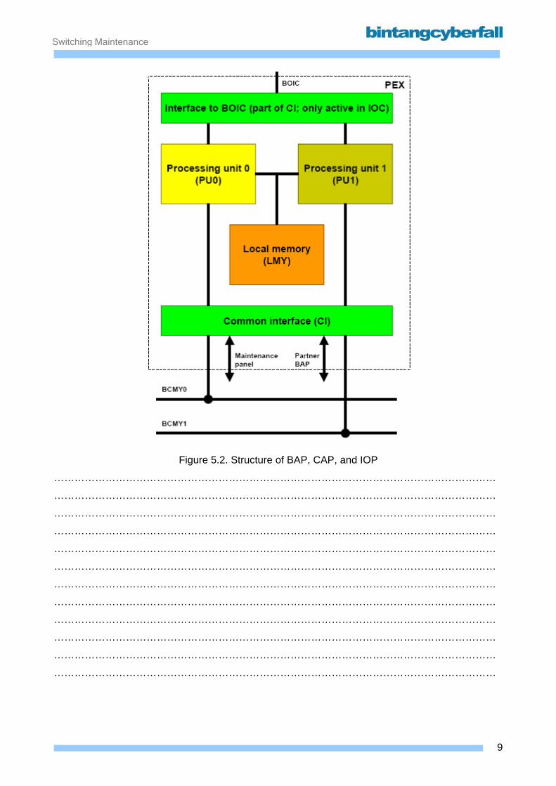
Switching Maintenance
Figure 5.2. Structure of BAP, CAP, and IOP
…………………………………………………………………………………………………………………
…………………………………………………………………………………………………………………
…………………………………………………………………………………………………………………
…………………………………………………………………………………………………………………
…………………………………………………………………………………………………………………
…………………………………………………………………………………………………………………
…………………………………………………………………………………………………………………
…………………………………………………………………………………………………………………
…………………………………………………………………………………………………………………
…………………………………………………………………………………………………………………
…………………………………………………………………………………………………………………
…………………………………………………………………………………………………………………
9BCCN2200 © 2007 Bintang CyberFall
Switching Maintenance
Input/Output Processors (IOP) Different types of input/output processors (IOP) connect the CP113C/CR with the other units in the
network node, the external memories, the operation and maintenance terminal or basic craft
terminal, the operation and maintenance center (OMC, via data lines) and computer centers (also
via data lines).
Input/Output Processor for Message Buffer The input/output processors for the message buffer (IOP:MB) are the CP113C/CR interfaces to
the functional units in the network node. All subsystems and functional units are supplied via two
IOP:MBs for reasons of operational reliability. If one of the two IOP:MBs fails, the remaining
processor takes over the data exchange functions by itself. The following units are connected to
the IOP:MB:
• the message buffer groups (MBG),
• the central clock generators (CCG),
The number of IOP:MBs used depends on the size of the switching network.
Input/Output Processor for Time and Alarms The input/output processor for time and alarms (IOP:TA) contains the hardware clock of the
CP113C/CR and interfaces for accepting external alarms. The duplicated hardware clock of the
IOP:TA is synchronized by a clock supplied by the central clock generator (CCG). The hardware
clock generates the date as well as the time in hours, minutes and seconds. The time is displayed
on the front panel of the module.
Alarms occur in racks of the CP area which cannot be assigned to specific functional units, e.g. fan
alarms. The IOP:TA accepts these alarms and reports them to the safeguarding software in the
BAP. The IOP:TA has alarm interfaces to a maximum of 5 racks.
10BCCN2200 © 2007 Bintang CyberFall

Switching Maintenance
Figure 5.3. Structure of the CP113C/CR input/output system
…………………………………………………………………………………………………………………
…………………………………………………………………………………………………………………
…………………………………………………………………………………………………………………
…………………………………………………………………………………………………………………
…………………………………………………………………………………………………………………
…………………………………………………………………………………………………………………
…………………………………………………………………………………………………………………
…………………………………………………………………………………………………………………
…………………………………………………………………………………………………………………
…………………………………………………………………………………………………………………
…………………………………………………………………………………………………………………
…………………………………………………………………………………………………………………
…………………………………………………………………………………………………………………
…………………………………………………………………………………………………………………
11BCCN2200 © 2007 Bintang CyberFall
Switching Maintenance
Input/Output Processor Unified for O&M Devices The following devices or lines can be connected via the input/output processor unified for O&M
devices (IOP:UNI):
• magnetic tape device (MTD),
• magnetic disk device (MDD),
and optionally:
• one O&M terminal (OMT or BCT) and 2 data lines or
• 3 data lines,
• magneto-optical disk unit (MOD).
The magneto-optical disk unit is used as a storage medium instead of or in addition to the
magnetic disk, to improve the operating activities, particularly to reduce the start up and backup
times. The MOD can be connected on the same SCSI bus as the MTD and MDD. At the interface
to the CP, the MOD is driven like an MTD. The maximum number of MOD/MTDs which can be
connected is 2 per IOP:UNI.
Three connections are provided for OMT/BCTs and data lines. One OMT and 2 data lines, or
alternatively 3 data lines, can be connected to them directly or via a Modem.
Input/Output Processor for Line Adaption Unit The input/output processor for line adaption unit (IOP:LAU) is used for connecting X.25-equipment
to the exchange, such as OMC or craft terminal. It consists of just a single module, the line control
unit module B, LCUB. The line adaption unit module B (module LAUB) is used for connecting the
IOP:LAU to the interface. The LAUB module is controlled by the line control unit. The two modules,
LCUB and LAUB, which are used together, are configured as follows:
• the LCUB module as IOPLAU (e.g. CONF IOP: IOP=IOPLAU-0, OST=ACT; )
• the LAUB module as LAU (e.g.: CONF LAU: LAU=0, OST=ACT; ).
The IOP:LAU is always used in pairs, with the two LCUBs being cross-connected to the two
LAUBs for reasons of operational reliability. A pair of IOP:LAUs is connected on one side to two
different BIOCs, and on the other side has 2 x 2 = 4 serial interfaces with BX.25/X.25 protocol, for
the connection of 4 data lines (X25LINK 0...3) using the LAPB data transmission procedure (Link
Access Procedure Balanced). The maximum data transmission rate is 64 kbit/s.
12BCCN2200 © 2007 Bintang CyberFall

Switching Maintenance
Input/Output Processor for Authentication Center The input/output processor for authentication center (IOP:AUC) is only available when the
CP113C is used in authentication centers (AC) in a mobile communication system. In a mobile
communication system, the authorization rights of the mobile subscriber are checked whenever a
call is set up between a mobile station and the network, with the objectives of protecting
• the mobile network against unauthorized access at user and customer level, and
• the authorized mobile subscriber against impermissible access to the mobile network by
unauthorized persons or by a subscriber attempting to pass off an invalid authorization as valid.
All important security functions are executed by the IOP:AUC in the AC. The IOP:AUC generates
the authentication triple required for the authentication process during call setup. This function is
particularly security-sensitive, and requires corresponding security measures. The IOP:AUC is
therefore also known as the security box.
To administer the subscriber data, the AC communicates with the personalization center for
subscriber identity module (PCS). Files containing the subscriber data are generated in the PCS
and transferred to the AC by means of a data line or magnetic tape. The files are encrypted to
ensure security during transmission. From a smartcard, the encoding parameters are loaded via a
serial interface to one IOP:AUC and are distributed to the other IOP:AUCs in the AC.
13BCCN2200 © 2007 Bintang CyberFall
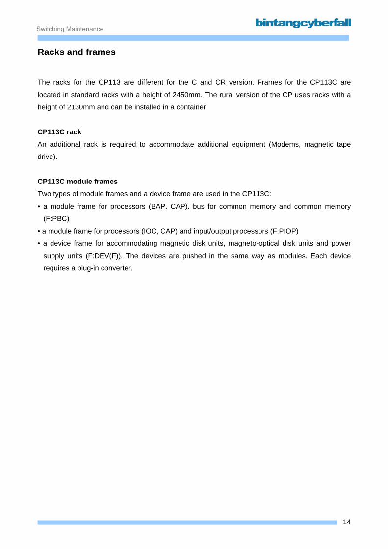
Switching Maintenance
Racks and frames The racks for the CP113 are different for the C and CR version. Frames for the CP113C are
located in standard racks with a height of 2450mm. The rural version of the CP uses racks with a
height of 2130mm and can be installed in a container.
CP113C rack An additional rack is required to accommodate additional equipment (Modems, magnetic tape
drive).
CP113C module frames Two types of module frames and a device frame are used in the CP113C:
• a module frame for processors (BAP, CAP), bus for common memory and common memory
(F:PBC)
• a module frame for processors (IOC, CAP) and input/output processors (F:PIOP)
• a device frame for accommodating magnetic disk units, magneto-optical disk units and power
supply units (F:DEV(F)). The devices are pushed in the same way as modules. Each device
requires a plug-in converter.
14BCCN2200 © 2007 Bintang CyberFall
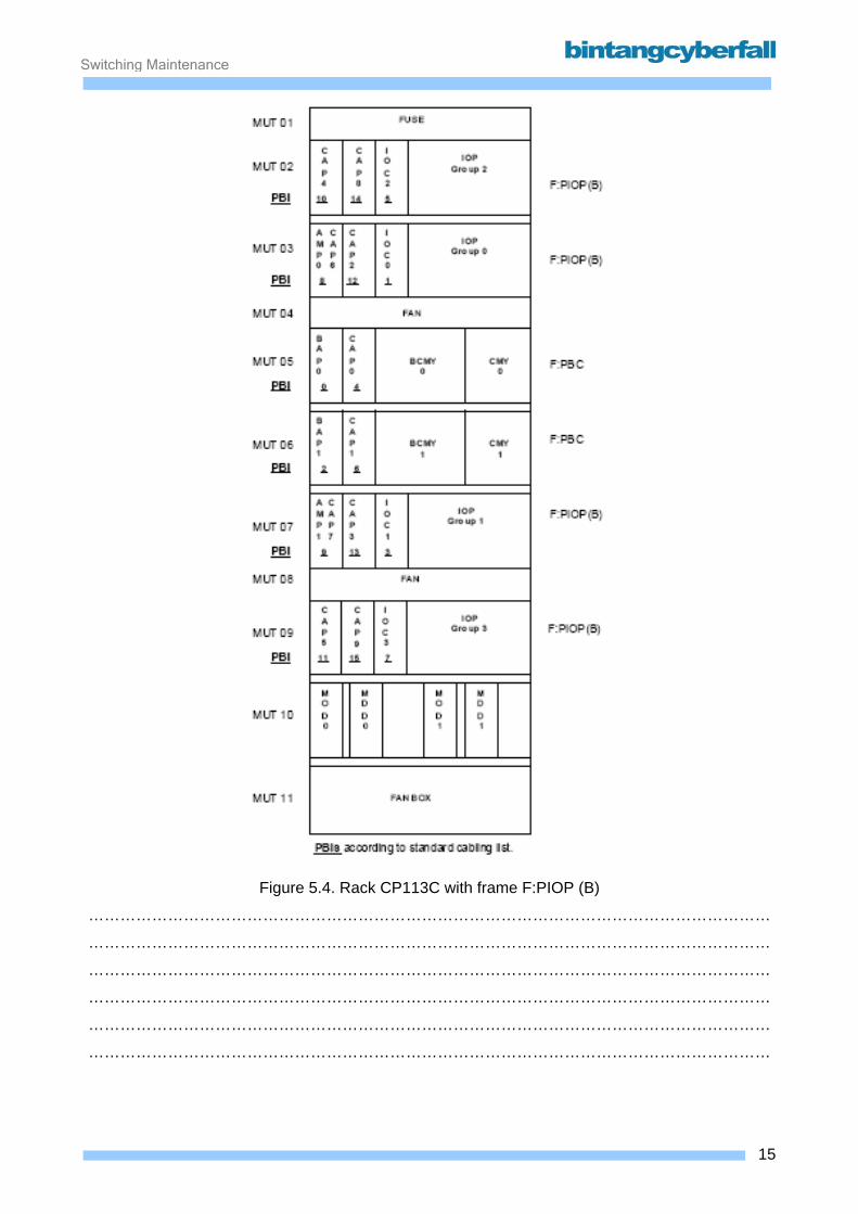
Switching Maintenance
Figure 5.4. Rack CP113C with frame F:PIOP (B)
…………………………………………………………………………………………………………………
…………………………………………………………………………………………………………………
…………………………………………………………………………………………………………………
…………………………………………………………………………………………………………………
…………………………………………………………………………………………………………………
…………………………………………………………………………………………………………………
15BCCN2200 © 2007 Bintang CyberFall
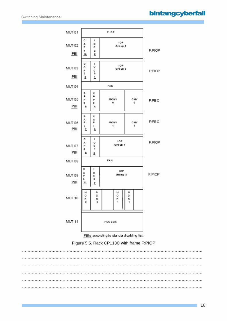
Switching Maintenance
Figure 5.5. Rack CP113C with frame F:PIOP
…………………………………………………………………………………………………………………
…………………………………………………………………………………………………………………
…………………………………………………………………………………………………………………
…………………………………………………………………………………………………………………
…………………………………………………………………………………………………………………
…………………………………………………………………………………………………………………
16BCCN2200 © 2007 Bintang CyberFall
Switching Maintenance
The following table shows the modules in the CP113C/CR and their assignments to the functional
units:
17BCCN2200 © 2007 Bintang CyberFall

Switching Maintenance
Figure 5.6. Module frame F:PBC
DCCx Direct current converter
PEX Program execution part
PIA Processor interface and arbiter
BCM Bus clock generator and maintenance controller
CMYC Common memory control
MTI Memory and tracer interface
CMYM Common memory medium
BAP Base processor
CAP Call processor
BCMY Bus for common memory
CMY Common memory
…………………………………………………………………………………………………………………
…………………………………………………………………………………………………………………
…………………………………………………………………………………………………………………
…………………………………………………………………………………………………………………
…………………………………………………………………………………………………………………
…………………………………………………………………………………………………………………
…………………………………………………………………………………………………………………
…………………………………………………………………………………………………………………
…………………………………………………………………………………………………………………
…………………………………………………………………………………………………………………
…………………………………………………………………………………………………………………
…………………………………………………………………………………………………………………
18BCCN2200 © 2007 Bintang CyberFall
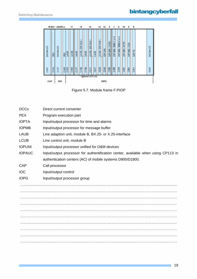
Switching Maintenance
Figure 5.7. Module frame F:PIOP
DCCx Direct current converter
PEX Program execution part
IOPTA Input/output processor for time and alarms
IOPMB Input/output processor for message buffer
LAUB Line adaption unit, module B, BX.25- or X.25-interface
LCUB Line control unit, module B
IOPUNI Input/output processor unified for O&M devices
IOPAUC Input/output processor for authentification center, available when using CP113 in
authentication centers (AC) of mobile systems D900/D1800.
CAP Call processor
IOC Input/output control
IOPG Input/output processor group
…………………………………………………………………………………………………………………
…………………………………………………………………………………………………………………
…………………………………………………………………………………………………………………
…………………………………………………………………………………………………………………
…………………………………………………………………………………………………………………
…………………………………………………………………………………………………………………
…………………………………………………………………………………………………………………
…………………………………………………………………………………………………………………
…………………………………………………………………………………………………………………
…………………………………………………………………………………………………………………
19BCCN2200 © 2007 Bintang CyberFall
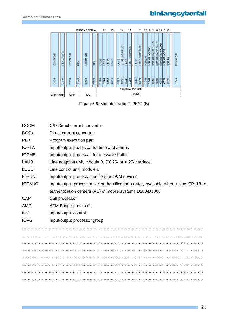
Switching Maintenance
Figure 5.8. Module frame F: PIOP (B)
DCCM C/D Direct current converter
DCCx Direct current converter
PEX Program execution part
IOPTA Input/output processor for time and alarms
IOPMB Input/output processor for message buffer
LAUB Line adaption unit, module B, BX.25- or X.25-interface
LCUB Line control unit, module B
IOPUNI Input/output processor unified for O&M devices
IOPAUC Input/output processor for authentification center, available when using CP113 in
authentication centers (AC) of mobile systems D900/D1800.
CAP Call processor
AMP ATM Bridge processor
IOC Input/output control
IOPG Input/output processor group
…………………………………………………………………………………………………………………
…………………………………………………………………………………………………………………
…………………………………………………………………………………………………………………
…………………………………………………………………………………………………………………
…………………………………………………………………………………………………………………
…………………………………………………………………………………………………………………
…………………………………………………………………………………………………………………
…………………………………………………………………………………………………………………
20BCCN2200 © 2007 Bintang CyberFall
Switching Maintenance
Advantages of new CP113E • call processors (CAP): performance improved by factor 5
• base processors (BAP): performance improved by factor 3,5
• ATM bridge processors (AMP): performance improved by factor 1,5
• input output controllers (IOC): performance improved by factor 2
• traffic handling capacity of more than 16 million busy hour call attempts (BHCA) possible
• no need for B:CMY what was the bottleneck in CP-internal communication
• can be adapted to network nodes of any size
• smaller footprint
• reduced power consumption
• CP113E has no effect on the system functions switching and operating (OAM). The interface to
the call processing SW and maintenance periphery remains unmodified.
• IOPs are directly taken over from the CP113C ; their performance is improved by a faster access
to CMY.
Capacity stages In the basic configuration the CP113E has only two base processors (BAP) and two input/output
controls (IOC). Up to sixteen input/output processors (IOP) can be connected to each IOC. For an
expansion, two more input/output controls (IOC) with additional IOP can be added. In its maximum
configuration the CP113E is equipped with 16 processors: two BAPs, four IOCs and 10 call
processors (CAP). Depending on the system configuration, up to four ATM bridge processors
(AMP) can also be used as an alternative to CAP.
In future configurations it will be possible to expand the CP113E by eight additional CAPs in order
to have a total of 24 processors. Of the eight additional processors, four can also be used as
AMPs.
The CP113E is connected via the input/output processors (IOP) to the message buffer D (MBD)
and to the OA&M equipment of the network node. There is a direct interface to the signaling
system network control (SSNC) via the ATM bridge processor (AMP). The asynchronous transfer
mode (ATM) is used at this interface. It reduces the CP load when distributing messages in the
network node.
21BCCN2200 © 2007 Bintang CyberFall
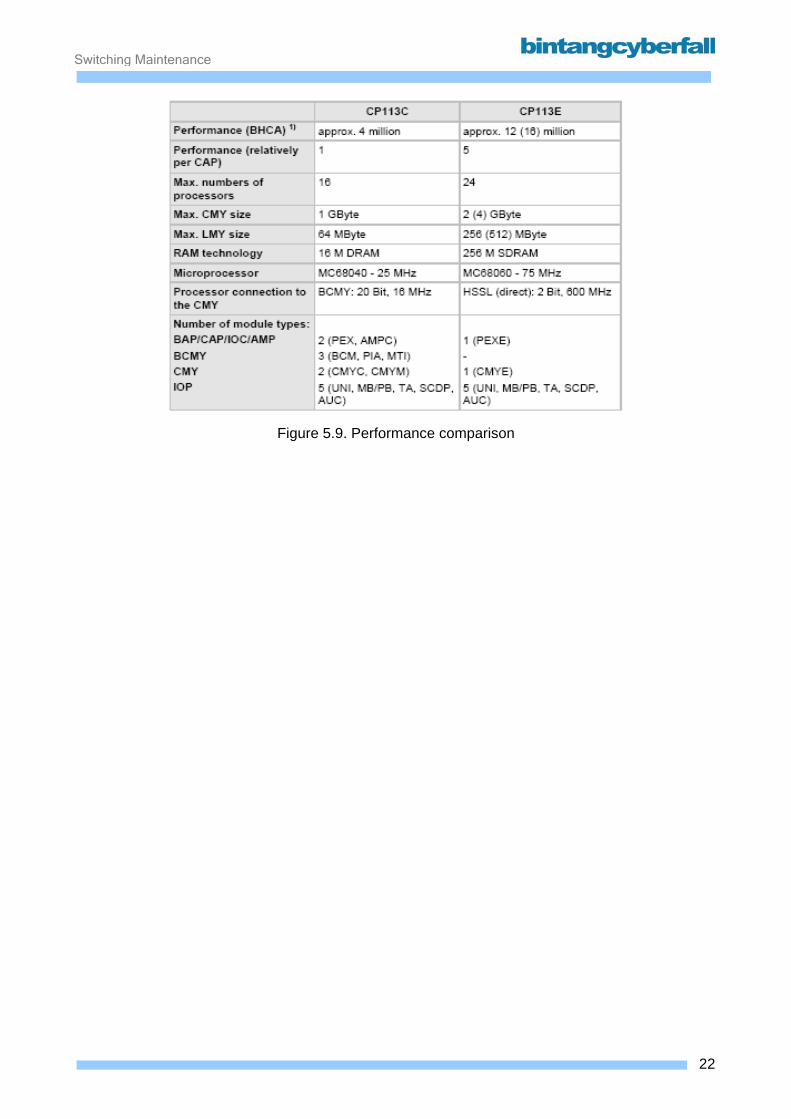
Switching Maintenance
Figure 5.9. Performance comparison
22BCCN2200 © 2007 Bintang CyberFall

Switching Maintenance
Redundancy The following functional units of the CP113E are duplicated:
• Base processor (BAP)
One of the two base processors (BAP) operates as “master” (BAPM), the other as “spare”
(BAPS). the BAPM processes operation and maintenance tasks as well as some of the call-
processing tasks. The BAPS processes call-processing tasks only. The two BAPs operate in
task and load sharing mode. If the BAPM fails, the BAPS takes over the tasks of the BAPM.
• Call processor (CAP)
The call processors (CAP) in CP113E handle call-processing tasks only. They work in load
sharing mode. Together with the BAPS and BAPM, the CAPs form a pool redundancy. As a
result, even if one processor fails (BAP or CAP), the CP113E can continue to handle the full
nominal load (n+1 redundancy).
• Input/output control (IOC)
The input/output controls (IOC) are duplicated. If one IOC fails, the other IOC carries out the
tasks of its partner unit.
• ATM bridge processor (AMP)
The AMPs are always operated in pairs in the CP113E. An AMP pair operates in working/spare
mode, i.e. both AMPs receive the same messages at the same time. However, only the active
AMP sends messages.
• Common memory (CMY)
The CMY is duplicated. Both CMYs (CMY0 and CMY1) can be reached by all processors and
input/output controls (IOC) as well as by the IOPs. In normal operation the two CMYs perform all
read and write cycles synchronously. However, the two CMYs can also be operated separately
(splitting mode). Access to the CMY by the processors is realized via High Speed Serial Links
(HSSL) that can transport data faster than the formerly used BCMY.
• Input/output processor (IOP)
The input/output processors (IOP) are grouped into two IOP groups in order to perform the tasks
of each other if an IOP in one IOPG should fail. The same IOP modules as in CP113C are used.
• Operation, administration and maintenance periphery
23BCCN2200 © 2007 Bintang CyberFall
Switching Maintenance
The redundant OA&M periphery units are always connected to two different IOCs. If one IOC or
the associated input/output processor (IOP) fails, inputs and outputs to/from the redundant
OA&M unit are carried out via the other IOC in the pair.
24BCCN2200 © 2007 Bintang CyberFall
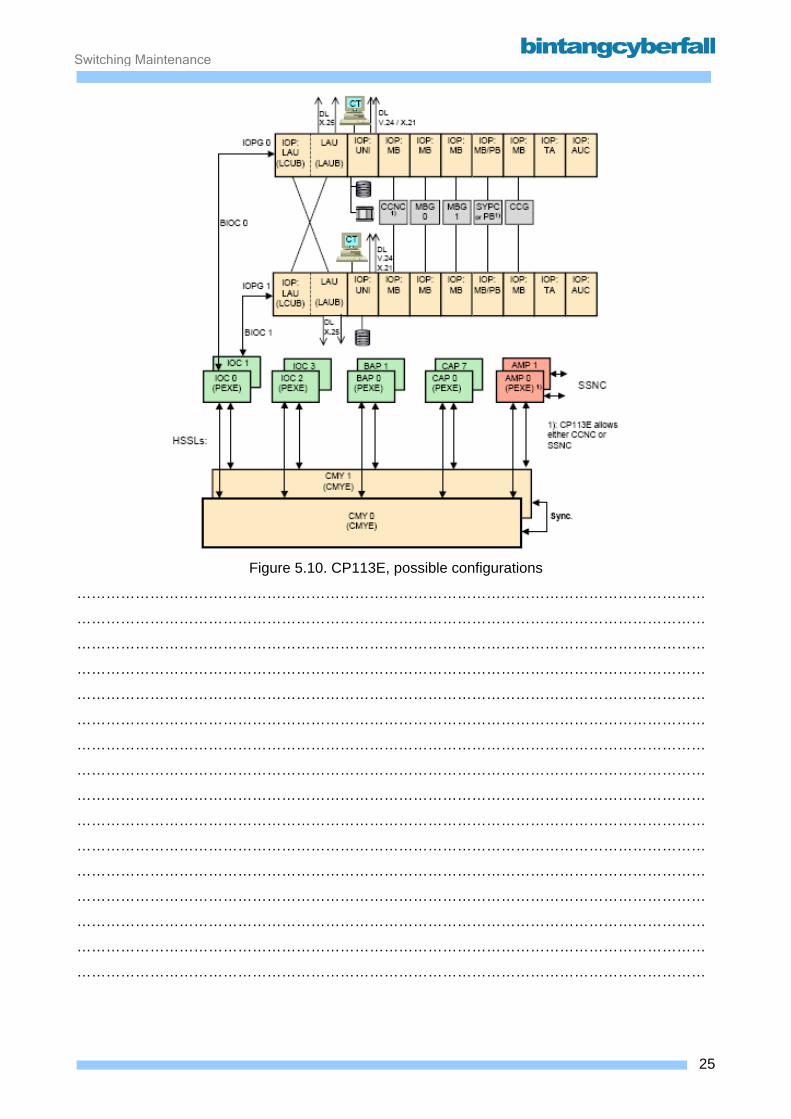
Switching Maintenance
Figure 5.10. CP113E, possible configurations
…………………………………………………………………………………………………………………
…………………………………………………………………………………………………………………
…………………………………………………………………………………………………………………
…………………………………………………………………………………………………………………
…………………………………………………………………………………………………………………
…………………………………………………………………………………………………………………
…………………………………………………………………………………………………………………
…………………………………………………………………………………………………………………
…………………………………………………………………………………………………………………
…………………………………………………………………………………………………………………
…………………………………………………………………………………………………………………
…………………………………………………………………………………………………………………
…………………………………………………………………………………………………………………
…………………………………………………………………………………………………………………
…………………………………………………………………………………………………………………
…………………………………………………………………………………………………………………
25BCCN2200 © 2007 Bintang CyberFall
Switching Maintenance
All the hardware in the CP113E is modularly designed, i.e. the functional units are implemented in
modules. One module corresponds to one hardware functional unit in this respect. In case of the
IOP:SCDP the hardware functional unit includes two modules. As already said, all IOPs are the
same as in CP113C.
Two new module types are introduced:
• Program Execution Board for CP113E (PEXE) for BAP, CAP, IOC, AMP and
• Common Memory for CP113E (CMYE)
26BCCN2200 © 2007 Bintang CyberFall
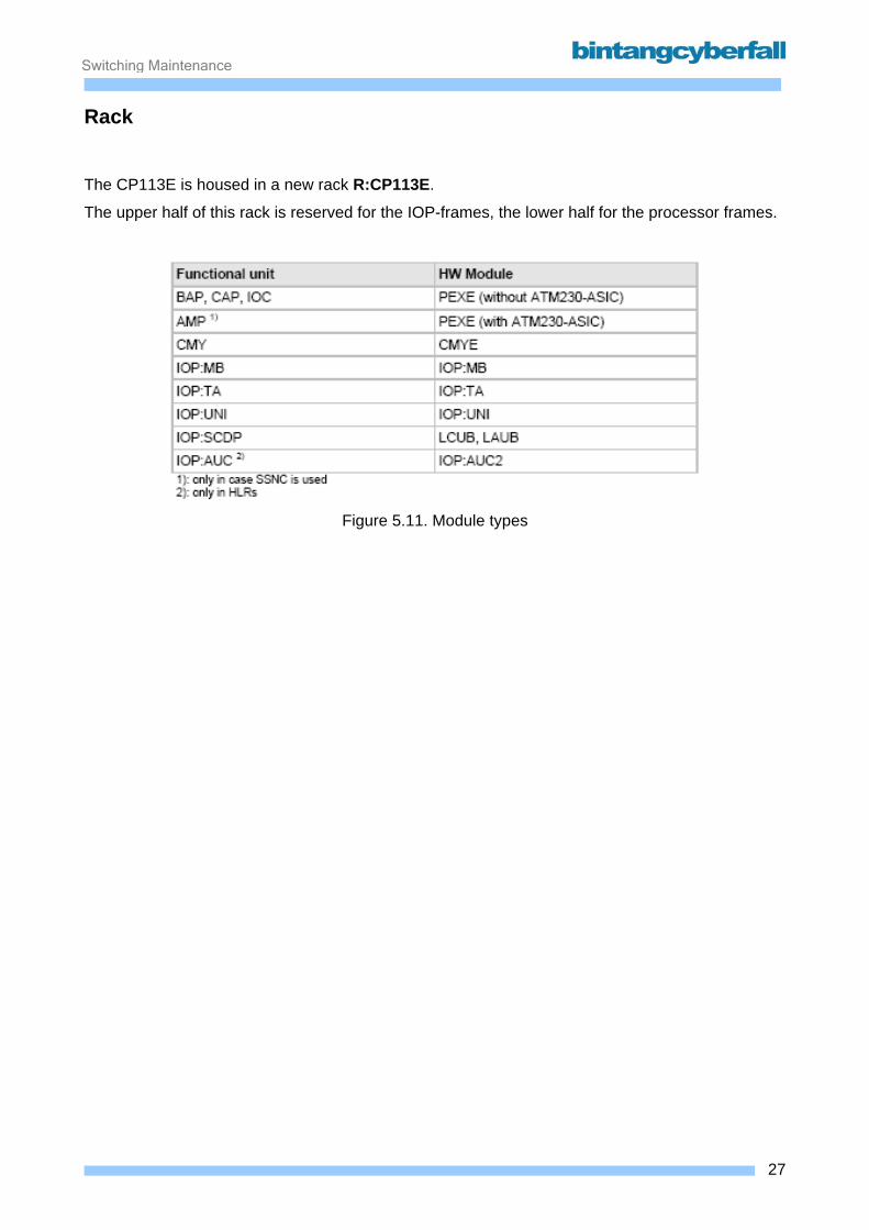
Switching Maintenance
Rack The CP113E is housed in a new rack R:CP113E.
The upper half of this rack is reserved for the IOP-frames, the lower half for the processor frames.
Figure 5.11. Module types
27BCCN2200 © 2007 Bintang CyberFall
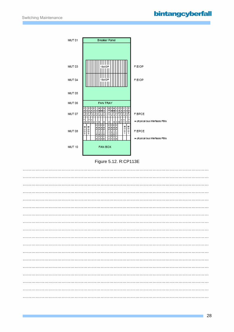
Switching Maintenance
Figure 5.12. R:CP113E
…………………………………………………………………………………………………………………
…………………………………………………………………………………………………………………
…………………………………………………………………………………………………………………
…………………………………………………………………………………………………………………
…………………………………………………………………………………………………………………
…………………………………………………………………………………………………………………
…………………………………………………………………………………………………………………
…………………………………………………………………………………………………………………
…………………………………………………………………………………………………………………
…………………………………………………………………………………………………………………
…………………………………………………………………………………………………………………
…………………………………………………………………………………………………………………
…………………………………………………………………………………………………………………
…………………………………………………………………………………………………………………
…………………………………………………………………………………………………………………
…………………………………………………………………………………………………………………
…………………………………………………………………………………………………………………
…………………………………………………………………………………………………………………
28BCCN2200 © 2007 Bintang CyberFall

Switching Maintenance
Frames Basic processor frame F:BPCE The F:BPCE comprises two backplane halves that are interconnected via a connection element
M:CONE. With SR10, only two AMPs are possible and a maximum of 10
Extension processor frame F:EPCE The F:EPCE houses the MODs, MDDs and (optionally) eight more CAPs or four more AMPs. But
these are not yet needed / possible with SR10.
29BCCN2200 © 2007 Bintang CyberFall
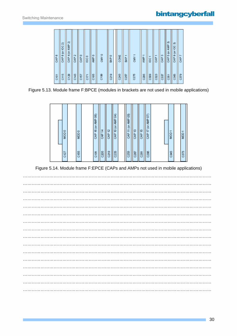
Switching Maintenance
Figure 5.13. Module frame F:BPCE (modules in brackets are not used in mobile applications)
Figure 5.14. Module frame F:EPCE (CAPs and AMPs not used in mobile applications)
…………………………………………………………………………………………………………………
…………………………………………………………………………………………………………………
…………………………………………………………………………………………………………………
…………………………………………………………………………………………………………………
…………………………………………………………………………………………………………………
…………………………………………………………………………………………………………………
…………………………………………………………………………………………………………………
…………………………………………………………………………………………………………………
…………………………………………………………………………………………………………………
…………………………………………………………………………………………………………………
…………………………………………………………………………………………………………………
…………………………………………………………………………………………………………………
…………………………………………………………………………………………………………………
…………………………………………………………………………………………………………………
…………………………………………………………………………………………………………………
…………………………………………………………………………………………………………………
30BCCN2200 © 2007 Bintang CyberFall
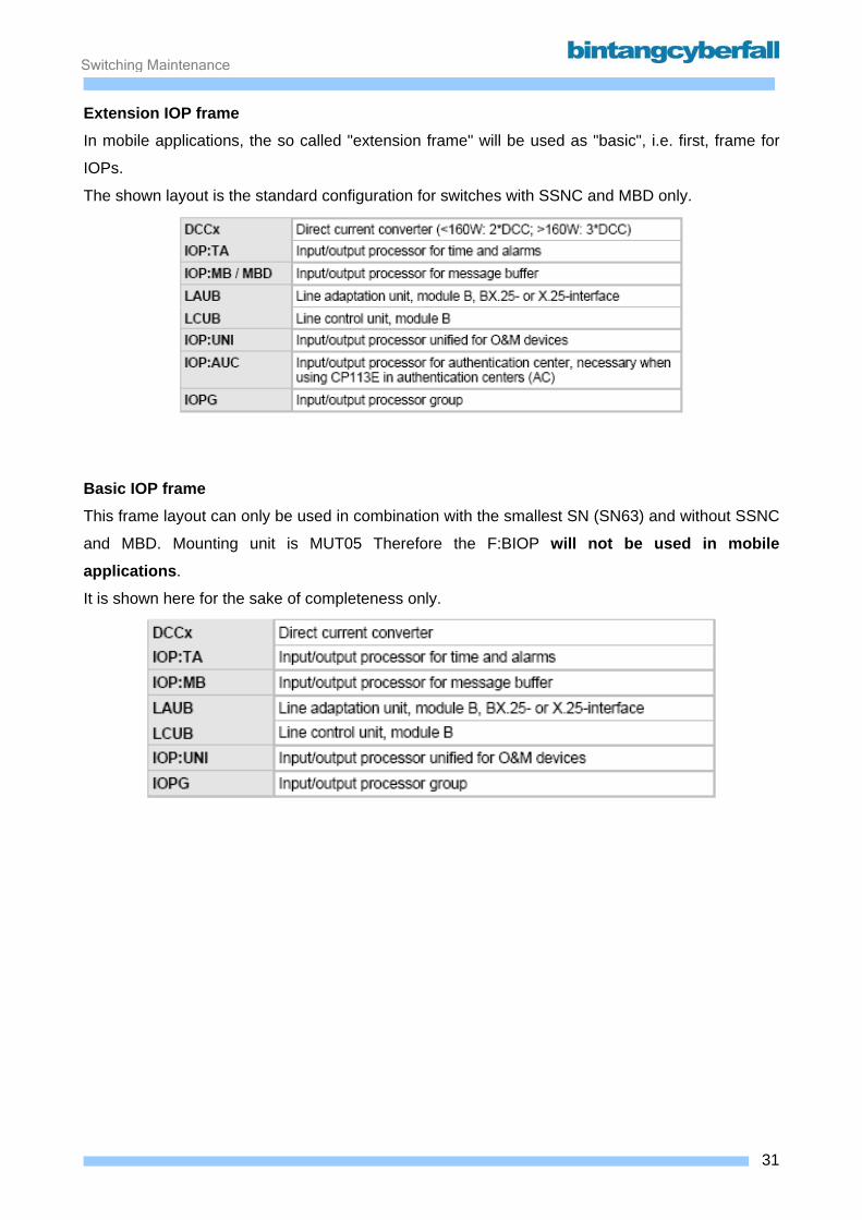
Switching Maintenance
Extension IOP frame In mobile applications, the so called "extension frame" will be used as "basic", i.e. first, frame for
IOPs.
The shown layout is the standard configuration for switches with SSNC and MBD only.
Basic IOP frame This frame layout can only be used in combination with the smallest SN (SN63) and without SSNC
and MBD. Mounting unit is MUT05 Therefore the F:BIOP will not be used in mobile applications.
It is shown here for the sake of completeness only.
31BCCN2200 © 2007 Bintang CyberFall
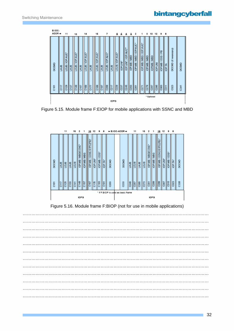
Switching Maintenance
Figure 5.15. Module frame F:EIOP for mobile applications with SSNC and MBD
Figure 5.16. Module frame F:BIOP (not for use in mobile applications)
…………………………………………………………………………………………………………………
…………………………………………………………………………………………………………………
…………………………………………………………………………………………………………………
…………………………………………………………………………………………………………………
…………………………………………………………………………………………………………………
…………………………………………………………………………………………………………………
…………………………………………………………………………………………………………………
…………………………………………………………………………………………………………………
…………………………………………………………………………………………………………………
…………………………………………………………………………………………………………………
…………………………………………………………………………………………………………………
…………………………………………………………………………………………………………………
32BCCN2200 © 2007 Bintang CyberFall

Switching Maintenance
5.2. Message Buffer
33BCCN2200 © 2007 Bintang CyberFall
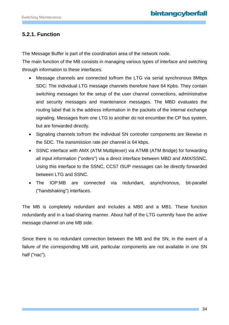
Switching Maintenance
5.2.1. Function
The Message Buffer is part of the coordination area of the network node.
The main function of the MB consists in managing various types of interface and switching
through information to these interfaces:
• Message channels are connected to/from the LTG via serial synchronous 8Mbps
SDC: The individual LTG message channels therefore have 64 Kpbs. They contain
switching messages for the setup of the user channel connections, administrative
and security messages and maintenance messages. The MBD evaluates the
routing label that is the address information in the packets of the internal exchange
signaling. Messages from one LTG to another do not encumber the CP bus system,
but are forwarded directly.
• Signaling channels to/from the individual SN controller components are likewise in
the SDC. The transmission rate per channel is 64 kbps.
• SSNC interface with AMX (ATM Multiplexer) via ATMB (ATM Bridge) for forwarding
all input information ("orders") via a direct interface between MBD and AMX/SSNC.
Using this interface to the SSNC, CCS7 ISUP messages can be directly forwarded
between LTG and SSNC.
• The IOP:MB are connected via redundant, asynchronous, bit-parallel
("handshaking") interfaces.
The MB is completely redundant and includes a MB0 and a MB1. These function
redundantly and in a load-sharing manner. About half of the LTG currently have the active
message channel on one MB side.
Since there is no redundant connection between the MB and the SN, in the event of a
failure of the corresponding MB unit, particular components are not available in one SN
half ("nac").
34BCCN2200 © 2007 Bintang CyberFall
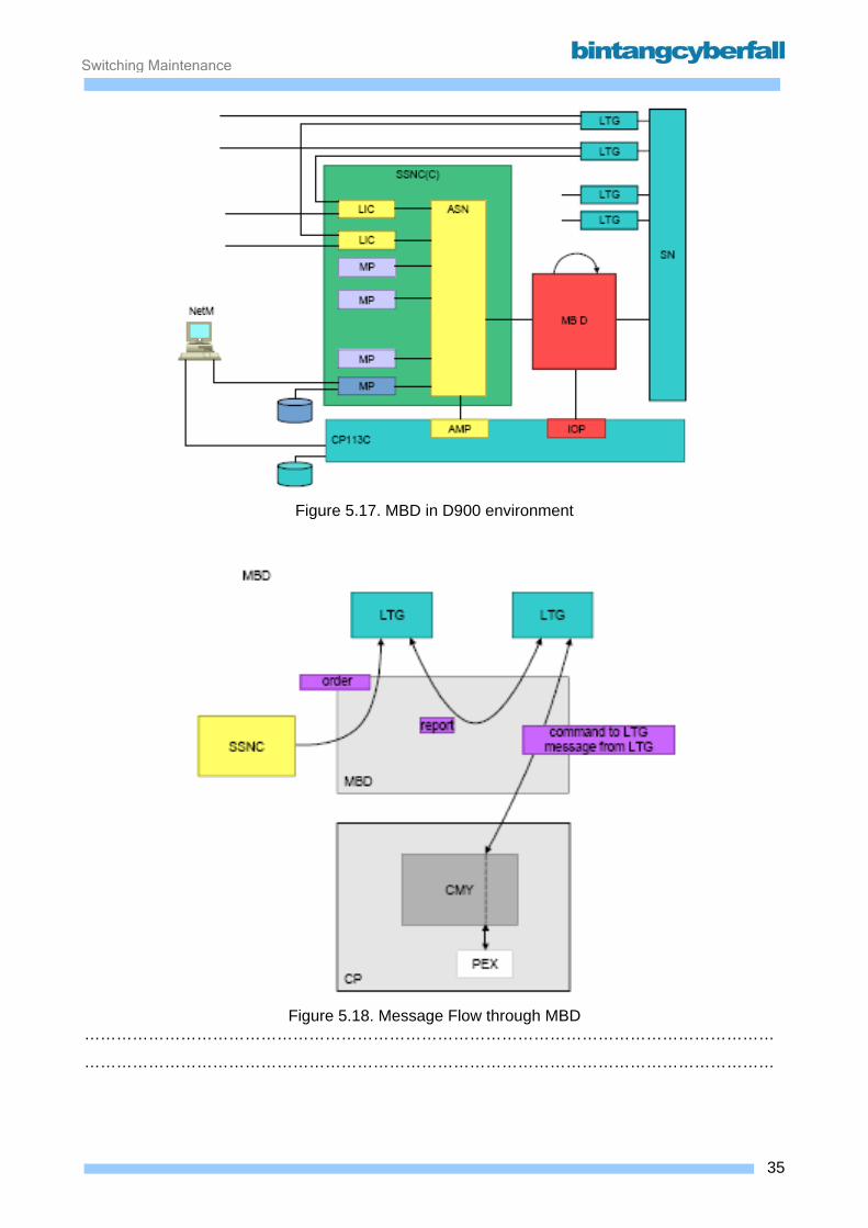
Switching Maintenance
Figure 5.17. MBD in D900 environment
Figure 5.18. Message Flow through MBD
…………………………………………………………………………………………………………………
…………………………………………………………………………………………………………………
35BCCN2200 © 2007 Bintang CyberFall
Switching Maintenance
5.2.2. Hardware and Location
The MBD is set up in the form of two redundant halves, which work independently of each other in
the load-sharing mode.
The MBD comprises four different module types:
The MBDH module takes over the processing of the HDLC interfaces concerning the LTGs and
SN. Each module provides LTG message channels to a maximum of four TSGs and six SGC
interfaces. The maximum number of LTGs that can be connected with an individual MBDH is 252.
The smallest possible MBD configuration with 63 LTGs based on one single MBDH, in which only
one SDC:TSG interface and two SDC:SGC interfaces are used. The MBD expansion stages 252,
504, ... 2016 are achieved in stages of 252 LTGs by connecting additional MBDH modules. The
maximum is 8 MBDH, i.e. a total of 2016 LTGs are therefore possible (SN D).
The MBDA module is connected with the SSNC via two ATM lines, each at a speed of 207 Mbit/s.
Each module can process approximately 24,000 #7 messages (ISUPMSU) per second (including
additional asymmetric load). One MBDA is the intended minimum, five MBDA modules is the
planned maximum.
Both the ATM bridges per MBDA are implemented in the form of fiber optic cables.
Per bridge, there are two FOTX modules on the rear panel of MBD module frame behind the
MBDA slot. They connect the two sides of the SSNC-ATM switching network. The fiber optic cable
transceiver module FOTX implements the electrical/optical conversion (Rx and Tx) of an ATM200
channel on the fiber optic cable connection.
The MBDC module has a maximum of seven interfaces with IOP:MB pairs on the CP113C. In
SR9, a maximum of two IOP:MB interfaces are used. Alongside its task as a CP message
transferor, this module takes over the control of the MBD in the case of a recovery and with regard
to a complete system reset. The MBDC can transfer up to 38,000 messages.
The MBDCG module receives its reference clock from the CCG and distributes these further to the
SN modules. Simultaneously, it also provides the individual MBD modules with the MBD system
clock. With regard to the SND, the MBDCG multiplexes multiple SN signaling channels to a single
8 Mbit/s interface ("S3").
The MBDH modules can be installed into a frame during operation ("hot plug-in").
36BCCN2200 © 2007 Bintang CyberFall

Switching Maintenance
With regard to installation, the continuous ascending sequence (MBDH0, MBDH1, ... MBDH7)
must be observed.
37BCCN2200 © 2007 Bintang CyberFall

Switching Maintenance
Figre 5.19. Hardware of the MBD
…………………………………………………………………………………………………………………
…………………………………………………………………………………………………………………
…………………………………………………………………………………………………………………
…………………………………………………………………………………………………………………
…………………………………………………………………………………………………………………
…………………………………………………………………………………………………………………
…………………………………………………………………………………………………………………
…………………………………………………………………………………………………………………
…………………………………………………………………………………………………………………
…………………………………………………………………………………………………………………
…………………………………………………………………………………………………………………
…………………………………………………………………………………………………………………
…………………………………………………………………………………………………………………
…………………………………………………………………………………………………………………
…………………………………………………………………………………………………………………
…………………………………………………………………………………………………………………
…………………………………………………………………………………………………………………
…………………………………………………………………………………………………………………
…………………………………………………………………………………………………………………
…………………………………………………………………………………………………………………
…………………………………………………………………………………………………………………
…………………………………………………………………………………………………………………
38BCCN2200 © 2007 Bintang CyberFall
Switching Maintenance
All modules are connected to one another via a serial high-speed interface, the so called IBUS (Internal Bus). IBUS takes over the entire communications transfer in the MBD and a module is
also connected with its redundant counterpart in the second MBD half via an IBUS connection. In
this way, the connection of a module with its communications partner can be performed directly, if
they are both located in the same MBD half. If the destination is located in the redundant part of
the MBD, this is carried out via an indirect connection, which can be routed via either of two
different communication paths. It can either first be sent to the partner module of the receiver in
the same MBD half, from where it is forwarded to the receiver on the other MBD side, or the
message is sent to the appropriate partner module of the sender in the other MBD half and
transferred from there to the receiver. As standard, the former method is chosen (after module
reset).
39BCCN2200 © 2007 Bintang CyberFall
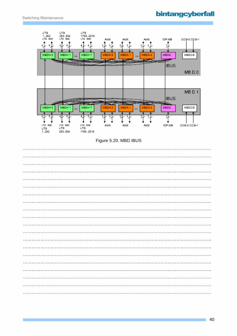
Switching Maintenance
Figure 5.20. MBD IBUS
…………………………………………………………………………………………………………………
…………………………………………………………………………………………………………………
…………………………………………………………………………………………………………………
…………………………………………………………………………………………………………………
…………………………………………………………………………………………………………………
…………………………………………………………………………………………………………………
…………………………………………………………………………………………………………………
…………………………………………………………………………………………………………………
…………………………………………………………………………………………………………………
…………………………………………………………………………………………………………………
…………………………………………………………………………………………………………………
…………………………………………………………………………………………………………………
…………………………………………………………………………………………………………………
…………………………………………………………………………………………………………………
…………………………………………………………………………………………………………………
…………………………………………………………………………………………………………………
…………………………………………………………………………………………………………………
…………………………………………………………………………………………………………………
…………………………………………………………………………………………………………………
…………………………………………………………………………………………………………………
40BCCN2200 © 2007 Bintang CyberFall
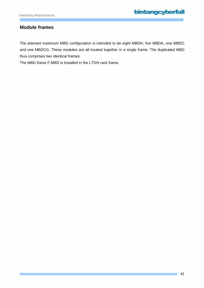
Switching Maintenance
Module frames The planned maximum MBD configuration is intended to be eight MBDH, five MBDA, one MBDC
and one MBDCG. These modules are all located together in a single frame. The duplicated MBD
thus comprises two identical frames.
The MBD frame F:MBD is installed in the LTGN rack frame.
41BCCN2200 © 2007 Bintang CyberFall
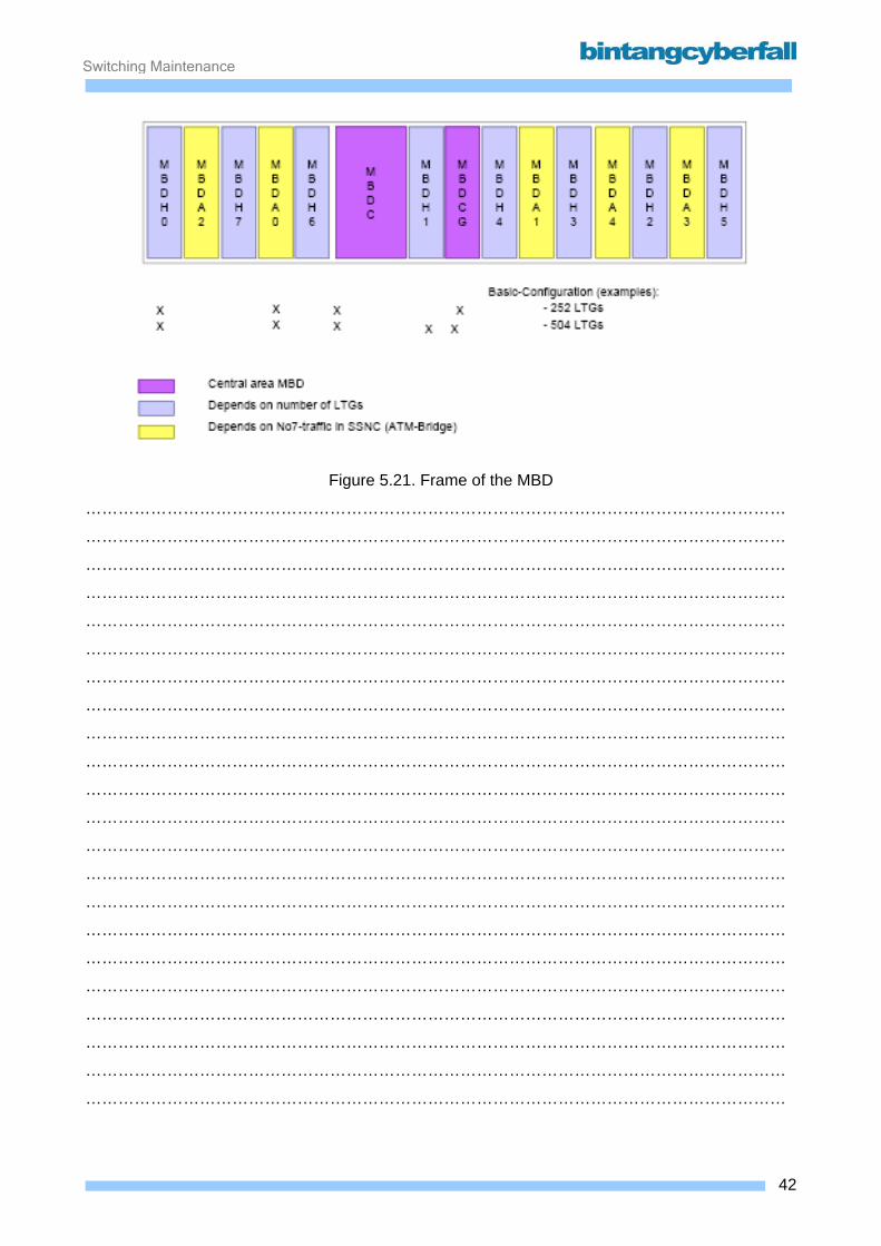
Switching Maintenance
Figure 5.21. Frame of the MBD
…………………………………………………………………………………………………………………
…………………………………………………………………………………………………………………
…………………………………………………………………………………………………………………
…………………………………………………………………………………………………………………
…………………………………………………………………………………………………………………
…………………………………………………………………………………………………………………
…………………………………………………………………………………………………………………
…………………………………………………………………………………………………………………
…………………………………………………………………………………………………………………
…………………………………………………………………………………………………………………
…………………………………………………………………………………………………………………
…………………………………………………………………………………………………………………
…………………………………………………………………………………………………………………
…………………………………………………………………………………………………………………
…………………………………………………………………………………………………………………
…………………………………………………………………………………………………………………
…………………………………………………………………………………………………………………
…………………………………………………………………………………………………………………
…………………………………………………………………………………………………………………
…………………………………………………………………………………………………………………
…………………………………………………………………………………………………………………
…………………………………………………………………………………………………………………
42BCCN2200 © 2007 Bintang CyberFall
Switching Maintenance
Expansion stages The number of required MBDH modules depends on the number of LTS to be connected. All
modules of the redundant MBD frame work according to the load sharing principle.
The number of required MBDA modules depends on the scope of the message (MSUs) being
exchanged between the MBD and the SSNC. For the highest expansion stage of SSNC (F:SCB
and 7xF:SCE), five 5 MBDA modules are required.
Each ATM bridge (2 per MBDA module) is "in service" on one side of a MB and "hot standby" on
the other.
The distribution of the ten ATMB interfaces (five modules with two ATM functions) must be
performed in accordance with the load sharing principle. Details regarding this can be found in the
handbook.
No MBDA module is required without SSNC or for emulation of MBB.
The number of IOP-MB modules required is determined by the traffic volume between the MBD
and CP. The MBDC module supports up to seven IOP:MB interfaces, so that one single MBDC
module suffices for all the expansion stages.
Currently, a maximum of 4 IOP:MB interfaces are used.
With the objective of uniform load sharing, there is an automatic allocation by the IOP:MB to
MBDH. In addition, an IOP:MB transmits the maintenance information flow to the MBDC module.
43BCCN2200 © 2007 Bintang CyberFall
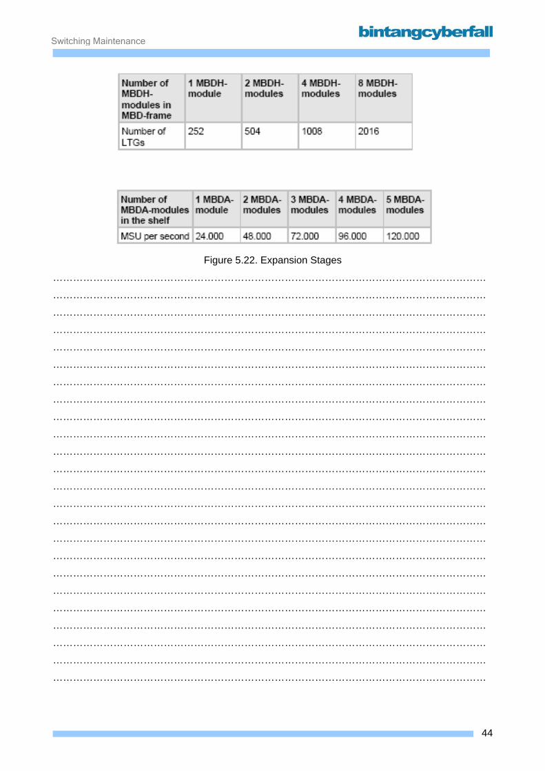
Switching Maintenance
Figure 5.22. Expansion Stages
…………………………………………………………………………………………………………………
…………………………………………………………………………………………………………………
…………………………………………………………………………………………………………………
…………………………………………………………………………………………………………………
…………………………………………………………………………………………………………………
…………………………………………………………………………………………………………………
…………………………………………………………………………………………………………………
…………………………………………………………………………………………………………………
…………………………………………………………………………………………………………………
…………………………………………………………………………………………………………………
…………………………………………………………………………………………………………………
…………………………………………………………………………………………………………………
…………………………………………………………………………………………………………………
…………………………………………………………………………………………………………………
…………………………………………………………………………………………………………………
…………………………………………………………………………………………………………………
…………………………………………………………………………………………………………………
…………………………………………………………………………………………………………………
…………………………………………………………………………………………………………………
…………………………………………………………………………………………………………………
…………………………………………………………………………………………………………………
…………………………………………………………………………………………………………………
…………………………………………………………………………………………………………………
…………………………………………………………………………………………………………………
44BCCN2200 © 2007 Bintang CyberFall

Switching Maintenance
5.3. Clock
45BCCN2200 © 2007 Bintang CyberFall
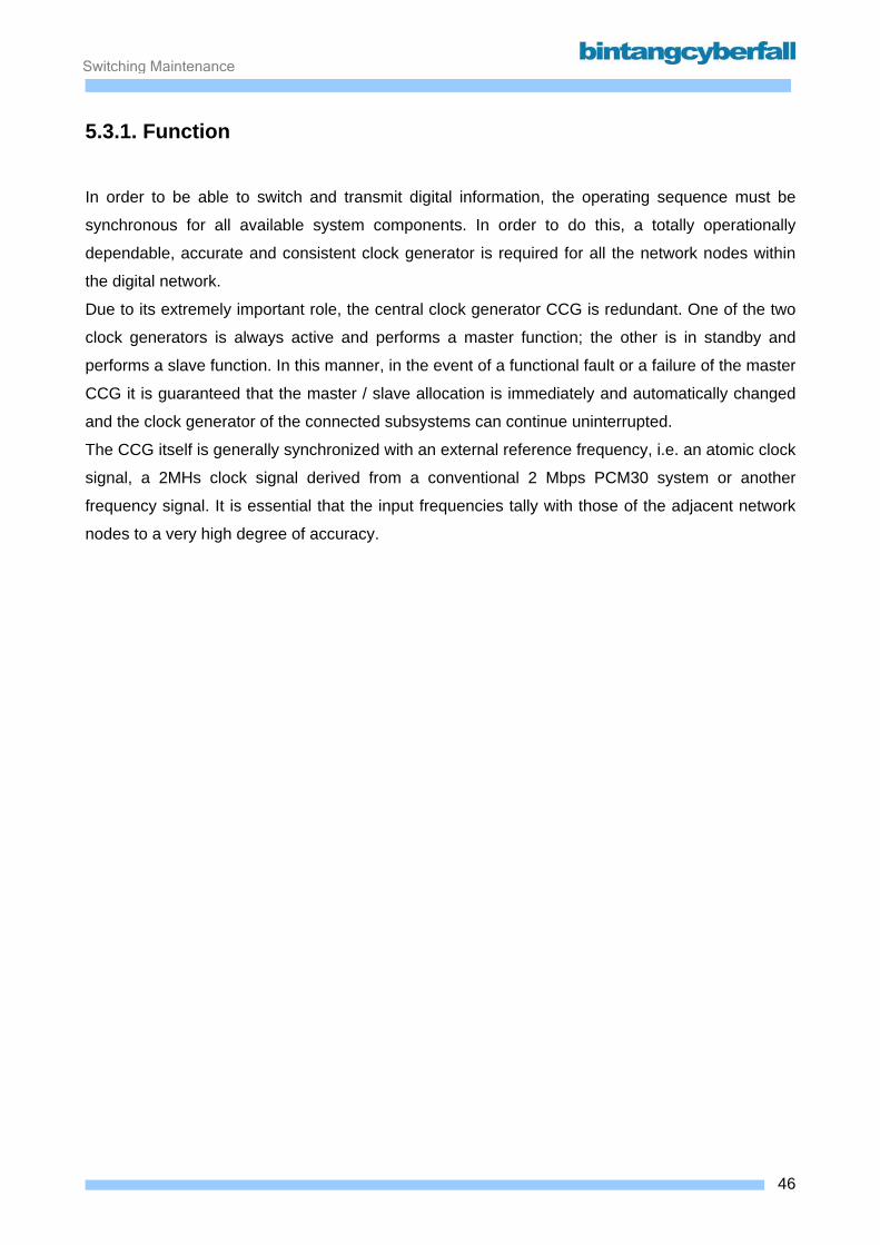
Switching Maintenance
5.3.1. Function
In order to be able to switch and transmit digital information, the operating sequence must be
synchronous for all available system components. In order to do this, a totally operationally
dependable, accurate and consistent clock generator is required for all the network nodes within
the digital network.
Due to its extremely important role, the central clock generator CCG is redundant. One of the two
clock generators is always active and performs a master function; the other is in standby and
performs a slave function. In this manner, in the event of a functional fault or a failure of the master
CCG it is guaranteed that the master / slave allocation is immediately and automatically changed
and the clock generator of the connected subsystems can continue uninterrupted.
The CCG itself is generally synchronized with an external reference frequency, i.e. an atomic clock
signal, a 2MHs clock signal derived from a conventional 2 Mbps PCM30 system or another
frequency signal. It is essential that the input frequencies tally with those of the adjacent network
nodes to a very high degree of accuracy.
46BCCN2200 © 2007 Bintang CyberFall
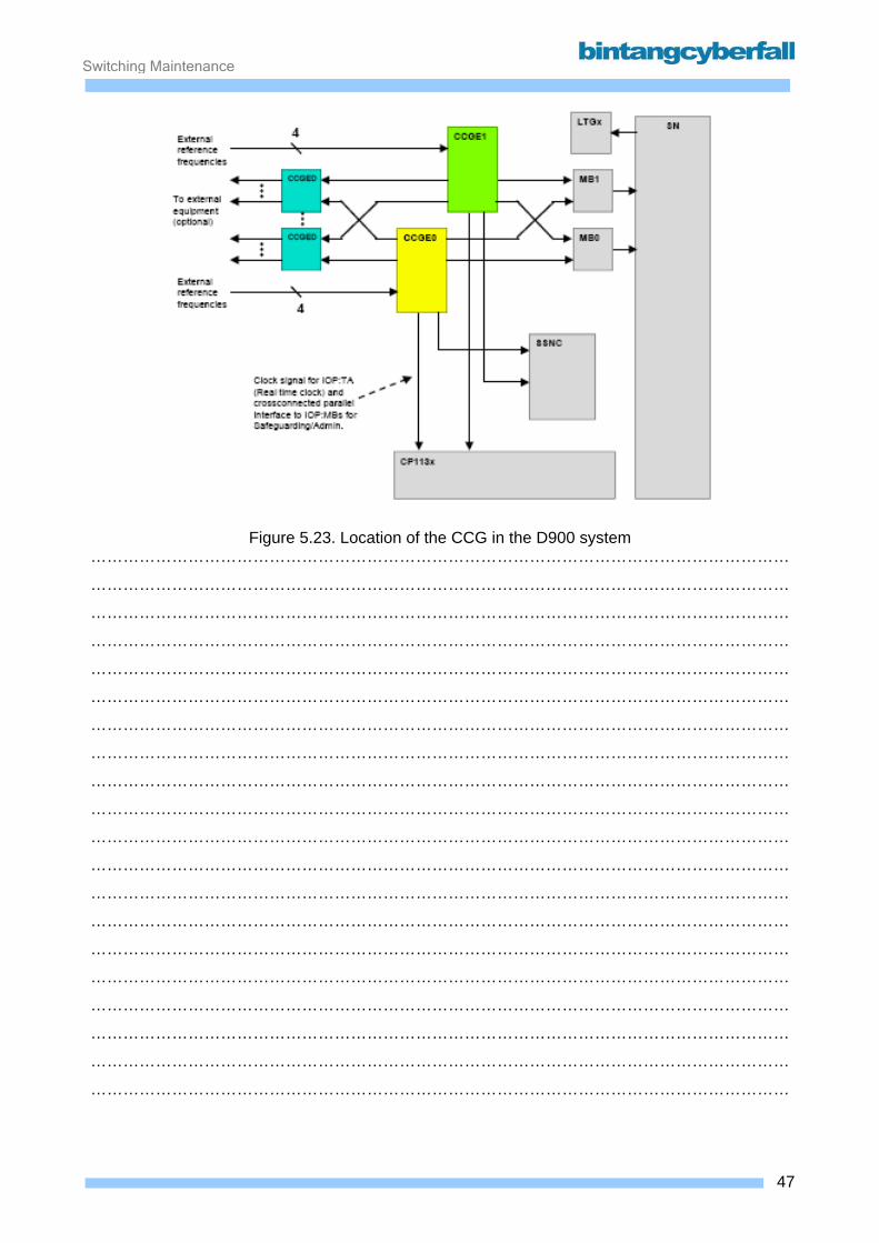
Switching Maintenance
Figure 5.23. Location of the CCG in the D900 system
…………………………………………………………………………………………………………………
…………………………………………………………………………………………………………………
…………………………………………………………………………………………………………………
…………………………………………………………………………………………………………………
…………………………………………………………………………………………………………………
…………………………………………………………………………………………………………………
…………………………………………………………………………………………………………………
…………………………………………………………………………………………………………………
…………………………………………………………………………………………………………………
…………………………………………………………………………………………………………………
…………………………………………………………………………………………………………………
…………………………………………………………………………………………………………………
…………………………………………………………………………………………………………………
…………………………………………………………………………………………………………………
…………………………………………………………………………………………………………………
…………………………………………………………………………………………………………………
…………………………………………………………………………………………………………………
…………………………………………………………………………………………………………………
…………………………………………………………………………………………………………………
…………………………………………………………………………………………………………………
47BCCN2200 © 2007 Bintang CyberFall

Switching Maintenance
5.3.2. Hardware and Location
The central clock generator comprises up to four module types, of which only one is
compulsorily required:
• the CCGES module contains the actual clock generator with oscillator and external master clock
input. The outgoing and monitored frequency signal from this module is used as the input clock
for the MB, IOP:TA, CCGED and, if necessary, the SSNC
• the CCGERB module may be used if no external reference frequencies can/should be used. It
contains a rubidium atom clock • the CCGE:GPS/DCF module is used, if satellite or special radio
frequency signals are to be received as a reference
• up to 4 optional CCGED modules for the distribution of the system clock to external systems, if
required the CCG can function in two operating modes:
• Synchronous operating mode (with at least one external reference signal)
• Plesiochronous operating mode (no external reference frequency "holdover").
Even if a reference frequency from the rubidium module is used, the term plesiochronous is used
because this reference does not come from a synchronization network.
In the synchronous operating mode, the CCG generates the clock using the built-in high-quality
oscillator and synchronizes it with one of the four possible external reference frequencies. The
active (master) CCG transmits the generated system to:
• the redundant message buffer (MB 0 and MB 1)
• the communication processor (time of day generator on the IOP:TA in the CP113x)
• the inactive (slave) CCG for the synchronization of the two CCG
• the external master clock distributor (CCGED), if desired
• the SSNC (ACCGs in the ASN)
The optionally available CCGED modules (external clock distributors) can be used in order to
output a 2048 kHz synchronous system clock to external systems, e.g. SDH transport systems.
Four modules can be installed, each with 32 outputs.
48BCCN2200 © 2007 Bintang CyberFall
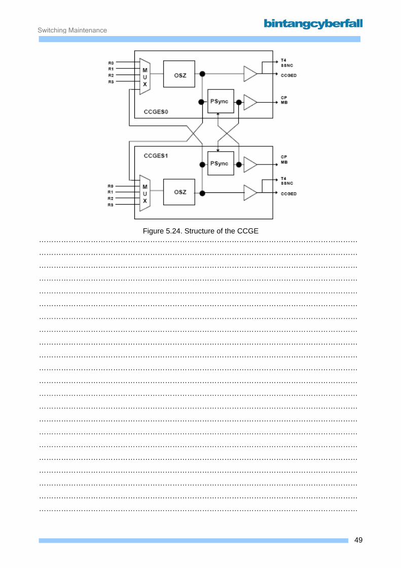
Switching Maintenance
Figure 5.24. Structure of the CCGE
…………………………………………………………………………………………………………………
…………………………………………………………………………………………………………………
…………………………………………………………………………………………………………………
…………………………………………………………………………………………………………………
…………………………………………………………………………………………………………………
…………………………………………………………………………………………………………………
…………………………………………………………………………………………………………………
…………………………………………………………………………………………………………………
…………………………………………………………………………………………………………………
…………………………………………………………………………………………………………………
…………………………………………………………………………………………………………………
…………………………………………………………………………………………………………………
…………………………………………………………………………………………………………………
…………………………………………………………………………………………………………………
…………………………………………………………………………………………………………………
…………………………………………………………………………………………………………………
…………………………………………………………………………………………………………………
…………………………………………………………………………………………………………………
…………………………………………………………………………………………………………………
…………………………………………………………………………………………………………………
…………………………………………………………………………………………………………………
…………………………………………………………………………………………………………………
49BCCN2200 © 2007 Bintang CyberFall
Switching Maintenance
Clock distribution Clock Generation In normal operation, the oscillators of the two redundant units CCGE0 and CCGE1 receive
different references for the clock generation. In the event of the failure of all the external
references, e.g. only on the CCGE0, it is received from the other CCG with an external reference
via an internal crossover (e.g. CCGE1).
The phase of the oscillators is not constant in normal operation when using different reference
signals. In order to simplify the switchover, the CCG standby output signals are synchronized for
the D900 internal clock users independently of the oscillators of the two units. To do this, the
output signal of the active unit is transferred to the standby unit via a further crossover connection.
Every clock receiver within the D900 network node (MB, CP, SSNC, external), which takes a
reference clock from the CCGE, is provided with the clock of the CCG, the respective other CCG
(standby) does not provide a clock.
The clock distribution in the network node is set up hierarchically. The clocks are generated,
synchronized and transmitted in several consecutive stages.
The pieces of hardware have their own clock generators at the respective levels.
These unit-specific oscillators are synchronized using the input clock coming from the
superordinate level. In the event of a failure of the clock signal of the superordinate level, the
subordinate clock generators continue in free-running operation. In this way, the operation of the
system can be continued to a certain extent. In this case, however, the quality of the interoffice
trunks to other network nodes is reduced. In the worst-case scenario, this can result in the failure
of user or signaling channels.
Self-monitoring CCGES self-monitoring detects all hardware faults with great accuracy. The CCGE outputs are not
individually monitored, but such faults must rather be detected by the connected clock receivers.
A control signal is sent from the active CCG to the standby. If this signal from the active redundant
partner unit is not transmitted, a switchover from standby to active is performed for the internal
D900 outputs without involving the CP.
50BCCN2200 © 2007 Bintang CyberFall
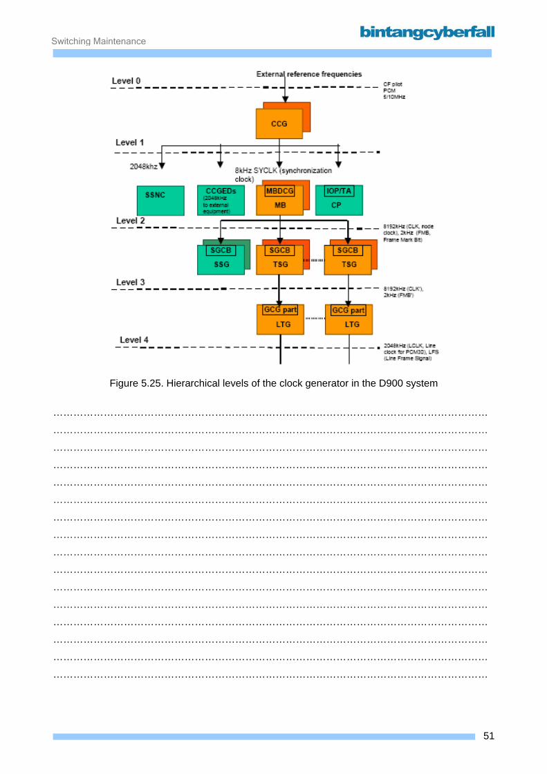
Switching Maintenance
Figure 5.25. Hierarchical levels of the clock generator in the D900 system
…………………………………………………………………………………………………………………
…………………………………………………………………………………………………………………
…………………………………………………………………………………………………………………
…………………………………………………………………………………………………………………
…………………………………………………………………………………………………………………
…………………………………………………………………………………………………………………
…………………………………………………………………………………………………………………
…………………………………………………………………………………………………………………
…………………………………………………………………………………………………………………
…………………………………………………………………………………………………………………
…………………………………………………………………………………………………………………
…………………………………………………………………………………………………………………
…………………………………………………………………………………………………………………
…………………………………………………………………………………………………………………
…………………………………………………………………………………………………………………
…………………………………………………………………………………………………………………
51BCCN2200 © 2007 Bintang CyberFall
Switching Maintenance
CCG module and module frame utilization The clock generators share one module frame, which accordingly consists of two halves with
identical modules.
The CCGED, CCGERB and CCGE:GPS are optional modules.
52BCCN2200 © 2007 Bintang CyberFall
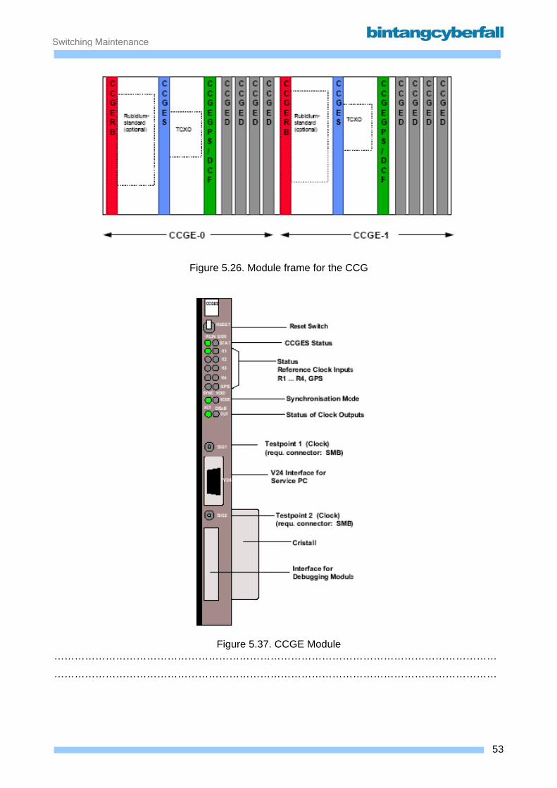
Switching Maintenance
Figure 5.26. Module frame for the CCG
Figure 5.37. CCGE Module
…………………………………………………………………………………………………………………
…………………………………………………………………………………………………………………
53BCCN2200 © 2007 Bintang CyberFall
Switching Maintenance
5.4. Operation and Maintenance Console
54BCCN2200 © 2007 Bintang CyberFall
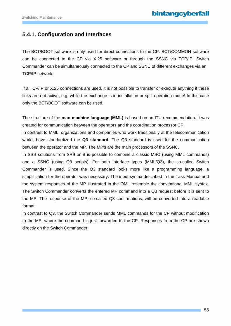
Switching Maintenance
5.4.1. Configuration and Interfaces
The BCT/BOOT software is only used for direct connections to the CP. BCT/COMMON software
can be connected to the CP via X.25 software or through the SSNC via TCP/IP. Switch
Commander can be simultaneously connected to the CP and SSNC of different exchanges via an
TCP/IP network.
If a TCP/IP or X.25 connections are used, it is not possible to transfer or execute anything if these
links are not active, e.g. while the exchange is in installation or split operation mode! In this case
only the BCT/BOOT software can be used.
The structure of the man machine language (MML) is based on an ITU recommendation. It was
created for communication between the operators and the coordination processor CP.
In contrast to MML, organizations and companies who work traditionally at the telecommunication
world, have standardized the Q3 standard. The Q3 standard is used for the communication
between the operator and the MP. The MP's are the main processors of the SSNC.
In SSS solutions from SR9 on it is possible to combine a classic MSC (using MML commands)
and a SSNC (using Q3 scripts). For both interface types (MML/Q3), the so-called Switch
Commander is used. Since the Q3 standard looks more like a programming language, a
simplification for the operator was necessary. The input syntax described in the Task Manual and
the system responses of the MP illustrated in the OML resemble the conventional MML syntax.
The Switch Commander converts the entered MP command into a Q3 request before it is sent to
the MP. The response of the MP, so-called Q3 confirmations, will be converted into a readable
format.
In contrast to Q3, the Switch Commander sends MML commands for the CP without modification
to the MP, where the command is just forwarded to the CP. Responses from the CP are shown
directly on the Switch Commander.
55BCCN2200 © 2007 Bintang CyberFall
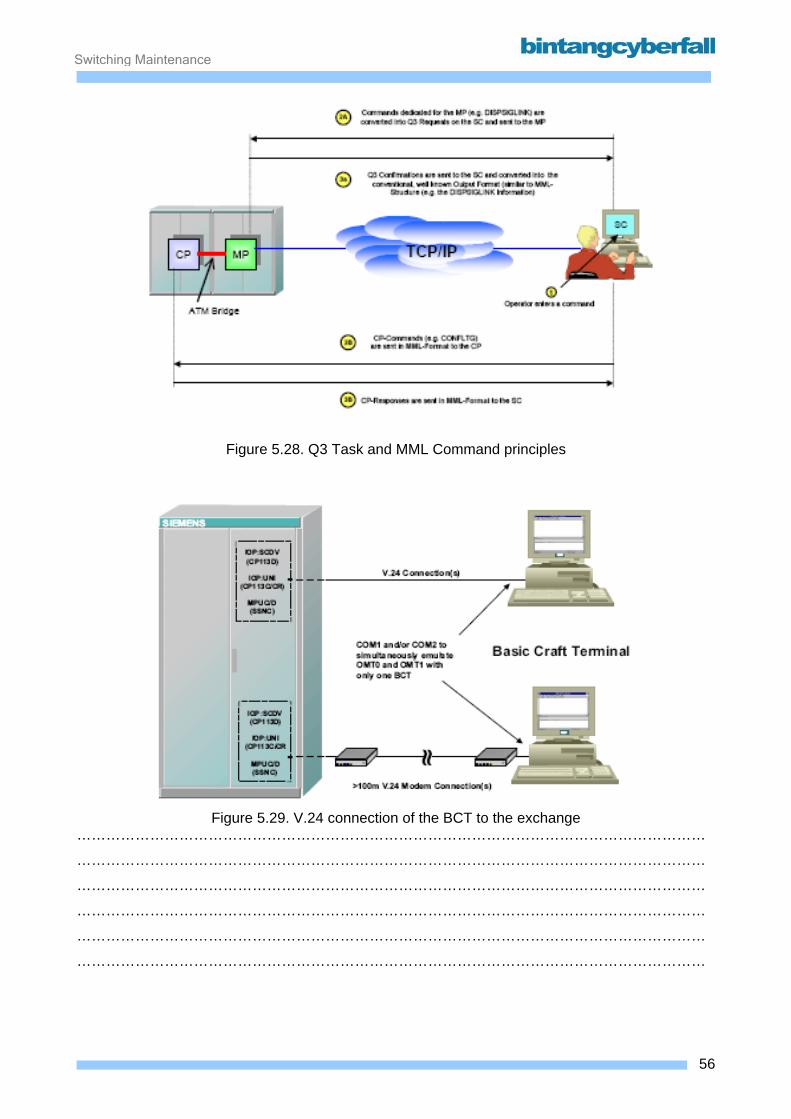
Switching Maintenance
Figure 5.28. Q3 Task and MML Command principles
Figure 5.29. V.24 connection of the BCT to the exchange
…………………………………………………………………………………………………………………
…………………………………………………………………………………………………………………
…………………………………………………………………………………………………………………
…………………………………………………………………………………………………………………
…………………………………………………………………………………………………………………
…………………………………………………………………………………………………………………
56BCCN2200 © 2007 Bintang CyberFall
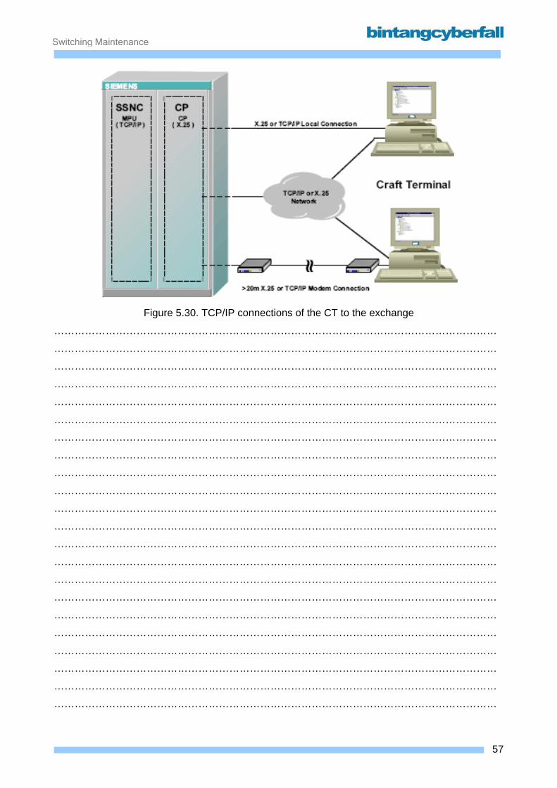
Switching Maintenance
Figure 5.30. TCP/IP connections of the CT to the exchange
…………………………………………………………………………………………………………………
…………………………………………………………………………………………………………………
…………………………………………………………………………………………………………………
…………………………………………………………………………………………………………………
…………………………………………………………………………………………………………………
…………………………………………………………………………………………………………………
…………………………………………………………………………………………………………………
…………………………………………………………………………………………………………………
…………………………………………………………………………………………………………………
…………………………………………………………………………………………………………………
…………………………………………………………………………………………………………………
…………………………………………………………………………………………………………………
…………………………………………………………………………………………………………………
…………………………………………………………………………………………………………………
…………………………………………………………………………………………………………………
…………………………………………………………………………………………………………………
…………………………………………………………………………………………………………………
…………………………………………………………………………………………………………………
…………………………………………………………………………………………………………………
…………………………………………………………………………………………………………………
…………………………………………………………………………………………………………………
…………………………………………………………………………………………………………………
57BCCN2200 © 2007 Bintang CyberFall

Switching Maintenance
5.4.2. Function
Functions of the BMML window Executing commands and login to the exchange Enter any command in the Command Input Line and press the ENTER key or use the execute
function of the Menu or Icon Bar. If there is no existing CP session, a dialogbox appears
requesting the Userid. After that, another dialog box with the password request is displayed.
Response of the system when parameters are missing If the user enters an incomplete command, the Input Request dialog box is used to request
missing parameters. It is possible to ignore a parameter by pressing ENTER.
If the parameter is requested again, it is mandatory. Otherwise the next parameter is prompted. To
finish a command, use the semicolon at any time.
BMML-window contents after command execution After a successful execution the BMML-window areas have the following contents:
Output Area
Output mask responded from the exchange depending on the executed command.
BMML-Command Input Line
The last entered command, again without parameters entered using the Input Request
dialog box.
Command History Area
The last up to 1024 commands in exactly the way they were entered in the BMML-Input
Line, without parameters entered with the aid of the Input Request dialog box!
The logging function The contents of the Output Area are automatically stored in a cyclic logfile on disk.
The size of this file can be changed by an administrator (e.g. 10MByte). When the file is full, older
entries are overwritten. Each of the two possible BMML-Windows has its own logfile. The name of
the logfile is BMMLlogX.txt where X is 1 for COM1 and 2 for COM2. The location on disk depends
on the installation, e.g. D:\bctboot\Logging\BMMLlog1.txt. This logfiles can be opened with a
simple text editor, but only an administrator can change or delete them.
58BCCN2200 © 2007 Bintang CyberFall
Switching Maintenance
Regardless of the size of this cyclic file, the maximum size of the Output Area is 500kByte, but
everything is still stored on disk.
Content of switch commander Switch Commander tree consists of multiple O&M software applications. These are:
• Alarm Console
• BMML
• Floor Plan Editor
• Interactive Document Browser
• Log Viewer
• Network Layer Manager
• Q3 Event Presentation Service
• Q3 Trace
• Refresh Status
• Switch Commander Administration
• Switch Commander Alarm and Message Display
• Switch Commander Information
• Switch Commander NE Administration
• Switch Commander Process Administration
• Scenario Wizard
• Task Analyzer
• Task Browser
• Trace Configuration
• Work Order Viewer
• Work Bench
59BCCN2200 © 2007 Bintang CyberFall

Switching Maintenance
5.5. Storages
60BCCN2200 © 2007 Bintang CyberFall

Switching Maintenance
5.5.1. Function
MDD stores APS for the system. The Applications Program System (APS) comprises the whole
Software (SW) and Firmware (FW), which is necessary for the Operation of the Switching System
EWSD/D900/D1800.
The APS comprises SW and FW as well and is programmed with e.g. CHILL (CCITT High Level
Language), C or Assembler. The APS runs and is stored in different locations. The following
overview shows the most important SW an FW locations.
• The SW in the Coordination Processor comprises data, resident SW and reloadable SW
as well. The resident SW is used for programs, which are more or less time critical (Call
processing, Operating System etc.). The reloadable SW is stored on the magnet disk an
reloaded if necessary. It is used for non time critical applications like Administration,
Configuration etc. The MDD also stores the SW for all other D900 Units except SSNC. The
FW in the Coordination Processor (CP) is used e.g. for the Boot of the System, i.e. the
situation when no SW is loaded yet.
• The Signaling System Network Control and its MDDs contain FW and SW with code and
data only for itself. The data is mainly consisting of the SS7- MTP and - SCCP information
necessary for the routing function and the message distribution to the corresponding user
parts.
• The Switching Network contains FW, which is necessary for e.g. the HW self supervision,
the through connection of the speech path etc.
• The LTG comprises SW and FW as well. The SW is stored on the magnetic disk and
loaded during the LTG Configuration and LTG Recoveries. The SW contains code to run
the LTG and data e.g. the application of ports, LTUs etc.. Similar to the CP the FW is e.g.
necessary to boot the LTG.
• The DLU/DSU contains SW and FW. The SW is used e.g. for the storage of the DLU Port
data. The FW is necessary for the DLU start up and for the Call Processing in the
emergency stand-alone.
61BCCN2200 © 2007 Bintang CyberFall
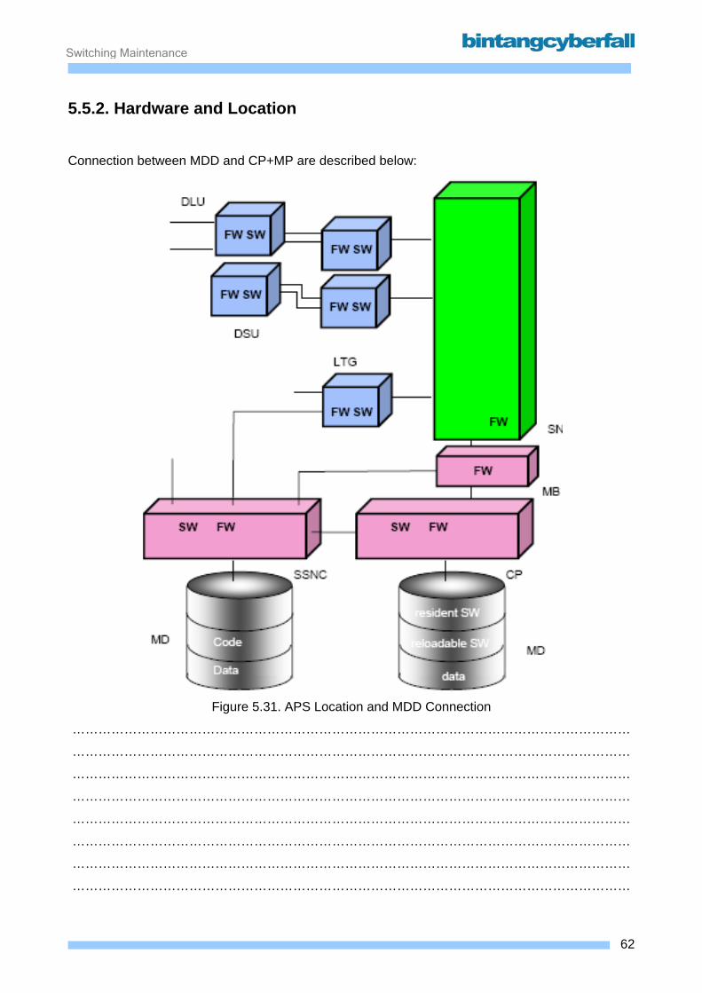
Switching Maintenance
5.5.2. Hardware and Location
Connection between MDD and CP+MP are described below:
Figure 5.31. APS Location and MDD Connection
…………………………………………………………………………………………………………………
…………………………………………………………………………………………………………………
…………………………………………………………………………………………………………………
…………………………………………………………………………………………………………………
…………………………………………………………………………………………………………………
…………………………………………………………………………………………………………………
…………………………………………………………………………………………………………………
…………………………………………………………………………………………………………………
62BCCN2200 © 2007 Bintang CyberFall

Switching Maintenance
Figure 5.32. Module MDDE – CP
…………………………………………………………………………………………………………………
…………………………………………………………………………………………………………………
…………………………………………………………………………………………………………………
…………………………………………………………………………………………………………………
…………………………………………………………………………………………………………………
…………………………………………………………………………………………………………………
…………………………………………………………………………………………………………………
…………………………………………………………………………………………………………………
…………………………………………………………………………………………………………………
…………………………………………………………………………………………………………………
…………………………………………………………………………………………………………………
…………………………………………………………………………………………………………………
…………………………………………………………………………………………………………………
…………………………………………………………………………………………………………………
…………………………………………………………………………………………………………………
…………………………………………………………………………………………………………………
63BCCN2200 © 2007 Bintang CyberFall
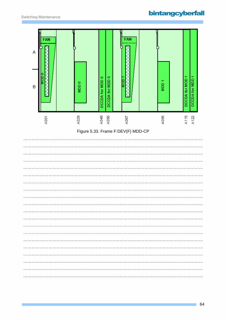
Switching Maintenance
Figure 5.33. Frame F:DEV(F) MDD-CP
…………………………………………………………………………………………………………………
…………………………………………………………………………………………………………………
…………………………………………………………………………………………………………………
…………………………………………………………………………………………………………………
…………………………………………………………………………………………………………………
…………………………………………………………………………………………………………………
…………………………………………………………………………………………………………………
…………………………………………………………………………………………………………………
…………………………………………………………………………………………………………………
…………………………………………………………………………………………………………………
…………………………………………………………………………………………………………………
…………………………………………………………………………………………………………………
…………………………………………………………………………………………………………………
…………………………………………………………………………………………………………………
…………………………………………………………………………………………………………………
…………………………………………………………………………………………………………………
…………………………………………………………………………………………………………………
…………………………………………………………………………………………………………………
…………………………………………………………………………………………………………………
…………………………………………………………………………………………………………………
64BCCN2200 © 2007 Bintang CyberFall
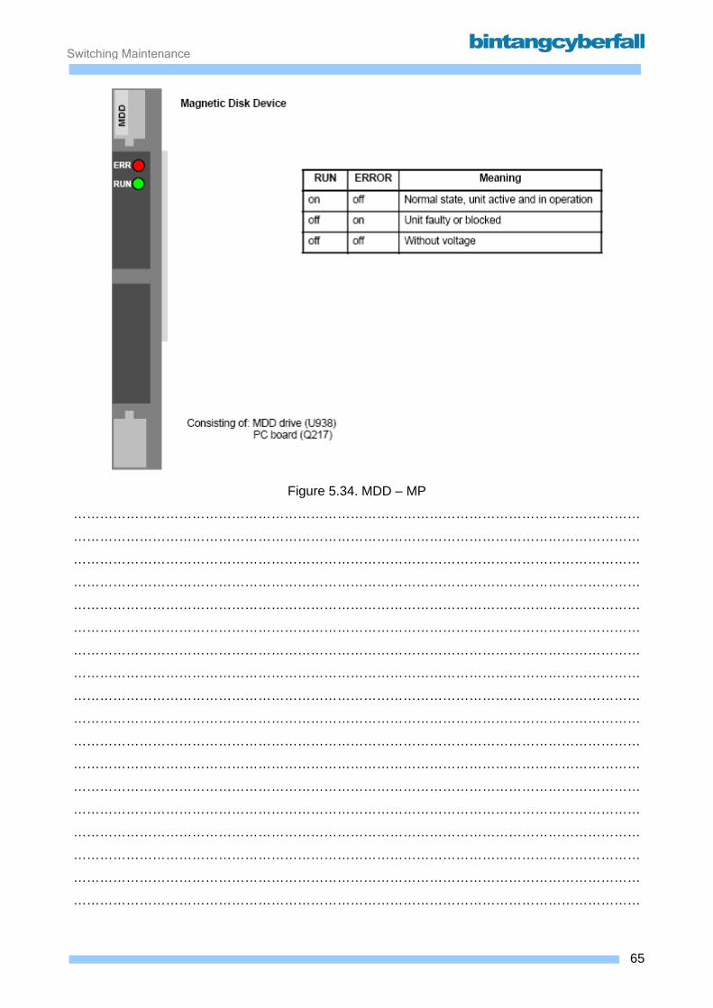
Switching Maintenance
Figure 5.34. MDD – MP
…………………………………………………………………………………………………………………
…………………………………………………………………………………………………………………
…………………………………………………………………………………………………………………
…………………………………………………………………………………………………………………
…………………………………………………………………………………………………………………
…………………………………………………………………………………………………………………
…………………………………………………………………………………………………………………
…………………………………………………………………………………………………………………
…………………………………………………………………………………………………………………
…………………………………………………………………………………………………………………
…………………………………………………………………………………………………………………
…………………………………………………………………………………………………………………
…………………………………………………………………………………………………………………
…………………………………………………………………………………………………………………
…………………………………………………………………………………………………………………
…………………………………………………………………………………………………………………
…………………………………………………………………………………………………………………
…………………………………………………………………………………………………………………
65BCCN2200 © 2007 Bintang CyberFall
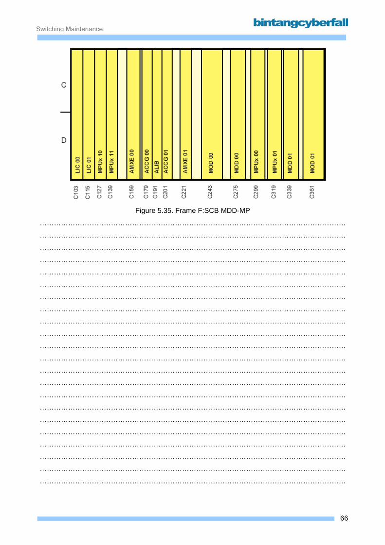
Switching Maintenance
Figure 5.35. Frame F:SCB MDD-MP
…………………………………………………………………………………………………………………
…………………………………………………………………………………………………………………
…………………………………………………………………………………………………………………
…………………………………………………………………………………………………………………
…………………………………………………………………………………………………………………
…………………………………………………………………………………………………………………
…………………………………………………………………………………………………………………
…………………………………………………………………………………………………………………
…………………………………………………………………………………………………………………
…………………………………………………………………………………………………………………
…………………………………………………………………………………………………………………
…………………………………………………………………………………………………………………
…………………………………………………………………………………………………………………
…………………………………………………………………………………………………………………
…………………………………………………………………………………………………………………
…………………………………………………………………………………………………………………
…………………………………………………………………………………………………………………
…………………………………………………………………………………………………………………
…………………………………………………………………………………………………………………
…………………………………………………………………………………………………………………
…………………………………………………………………………………………………………………
…………………………………………………………………………………………………………………
66BCCN2200 © 2007 Bintang CyberFall

Switching Maintenance
5.5.3. Procedures
An APS generation is a set of system files, which are necessary to run a switching system.
One (valid) generation in the CP is belonging to a "partner"-generation in the SSNC and vice
versa. Such a pair is normally created at the same time and linked together by a number called
generation compatibility sign "gcs".
An APS generation can be used as a current generation (the generation files are currently used
for the switching system) or as a fallback generation (the generation is kept on an external
memory: magnetic disk, magneto optical disk or magnetic tape) for a fallback in case of an
emergency situation. The current generations in CP and SSNC always have the same gcs. Also
each valid fallback generation has a partner with the same gcs.
New Generation after Data base extension
In case of the size of certain database tables is not sufficient any more (e.g. no Trunk Groups can
be created any more) or after implementation of a new APS the size of the data tables is to be
expanded with the Office Data Generator (ODAGEN). In this case the corresponding data tables
are expanded in a copy of the current APS. After successful expansion of the APS, the system
starts up with this new APS (ODAGEN Generation). Fallback Generations Routine and quarterly Saving
In some unusual emergency situations the system may not be able to work successfully with the
current APS, it will automatically (or by operator request) fall back to an older APS (fallback-
generation). This happens at the same time in CP and SSNC. Automatic Fallback cannot use
generations on MOD or invalid, locked or disabled generations on MDD.
In other cases it might happen, that there is no more generation on disk, which is able to start-up:
By operator-request, a generation on magneto optical disk will be used to reload the system.
Therefore the current generations of CP and SSNC are copied to MDD and MOD, inclusive the
current database, at least in an interval of two weeks and all three month with an additional start
up test in the CP (Backup Generation and Golden Generation). After APS Change In case of the introduction of a new APS version, a copy of the new APS is saved after run in of
the database. This APS copy can also be used for recoveries with a fall back (Golden Generation)
67BCCN2200 © 2007 Bintang CyberFall
Switching Maintenance
6. Switching Subsystem – Signaling Function
Contents 6.1. CCS7 Introduction ..................................................................................................................... 2
6.1. 1. Protocol Stack.................................................................................................................... 3 6.1.2. Sample of Procedure ........................................................................................................ 12
6.2. Signaling Component .............................................................................................................. 18 6.2.1. Function ............................................................................................................................ 19 6.2.2. Hardware and Location ..................................................................................................... 21
1BCCN2200 © 2007 Bintang CyberFall

Switching Maintenance
6.1. CCS7 Introduction
2BCCN2200 © 2007 Bintang CyberFall
Switching Maintenance
6.1. 1. Protocol Stack
The purpose of signaling system is to transfer control information (signal units) between elements
in telecommunication network. The elements are switches, operations centers, and databases.
Originally, signaling systems were designed to setup connections between telephone offices and
customer premises equipment (CPE) in order to transport only voice traffic through a voice-
oriented, analog network. Today, they are designed to set up connections between service
provider offices and CPE in order to transport not only voice but also video or data signals through
either analog or a digital network.
CCS7 is a successor of Common Channel Signaling number 6. CCS7 serves telecommunication
standards for years, and still can be used for next telecommunication system, e.g: IP based
telecommunication.
In GSM system signaling functions in CCS7 are distributed among the following parts:
• message transfer part (MTP)
• function-specific user parts (UP) The message transfer part represents a user-neutral means of transport for messages between
the users. These parts build lower levels of the signaling that support many kind of user parts. The
term user is applied here for all functional units which use the transport capability of the message
transfer part. Each user part encompasses the functions, protocols and coding for the signaling via
CCS7 for a specific user type (e.g. telephone service, data service, ISDN). In this way, the user
parts control the set-up and release of circuit connections, the processing of facilities as well as
administration and maintenance functions for the circuits. The functions of the message transfer
part and the user parts of CCS7 are divided into 4 levels. Levels 1 to 3 are allotted to the message
transfer part while the user parts form level 4.
Message Transfer Part
The message transfer part (MTP) is used in CCS7 by all user parts as a transport system for
message exchange. Messages to be transferred from one user part to another are given to the
message transfer part (Fig. 10 Functional CCS7 levels). The message transfer part ensures that
the messages reach the addressed user part in the correct order without information loss,
duplication or sequence alteration and without any bit errors.
3BCCN2200 © 2007 Bintang CyberFall
Switching Maintenance
Functional levels of MTP Level 1 (signaling data link) defines the physical, electrical and functional characteristics of a
signaling data link and the access units. Level 1 represents the bearer for a signaling link. In a
digital network, 64-kbit/s channels are generally used as signaling data links.
Level 2 (signaling link) defines the functions and procedures for a correct exchange of user
messages via a signaling link. The following functions must be carried out in level 2:
• delimitation of the signal units by flags and elimination of superfluous flags
• error detection using check bits and error correction by retransmitting signal units
• restoration of fault-free operation, for example, after disruption of the signaling data link
Level 3 (signaling network) defines the interworking of the individual signaling links.
A distinction is made between the two following functional areas:
• message routing, message discrimination and message distribution
• signaling network management
4BCCN2200 © 2007 Bintang CyberFall
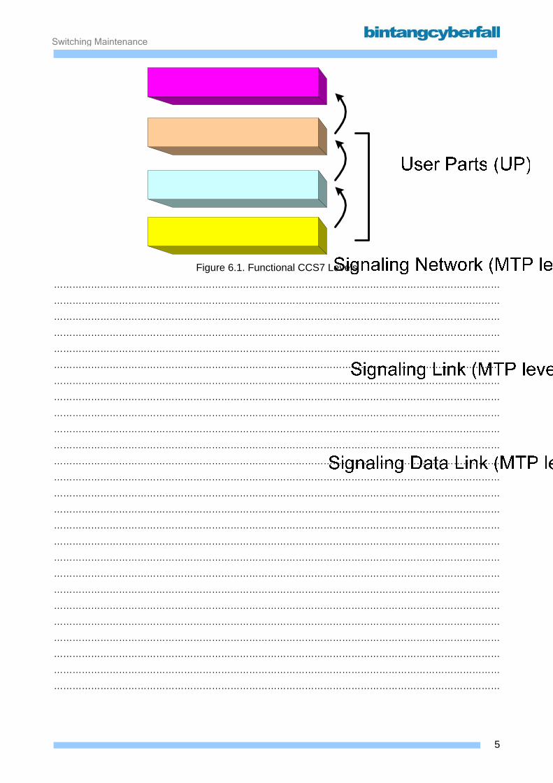
Switching Maintenance
Figure 6.1. Functional CCS7 Levels
………………………………………………………………………………………………………………………………
………………………………………………………………………………………………………………………………
………………………………………………………………………………………………………………………………
………………………………………………………………………………………………………………………………
………………………………………………………………………………………………………………………………
………………………………………………………………………………………………………………………………
………………………………………………………………………………………………………………………………
………………………………………………………………………………………………………………………………
………………………………………………………………………………………………………………………………
………………………………………………………………………………………………………………………………
………………………………………………………………………………………………………………………………
………………………………………………………………………………………………………………………………
………………………………………………………………………………………………………………………………
………………………………………………………………………………………………………………………………
………………………………………………………………………………………………………………………………
………………………………………………………………………………………………………………………………
………………………………………………………………………………………………………………………………
………………………………………………………………………………………………………………………………
………………………………………………………………………………………………………………………………
………………………………………………………………………………………………………………………………
………………………………………………………………………………………………………………………………
………………………………………………………………………………………………………………………………
………………………………………………………………………………………………………………………………
………………………………………………………………………………………………………………………………
………………………………………………………………………………………………………………………………
………………………………………………………………………………………………………………………………
5BCCN2200 © 2007 Bintang CyberFall

Switching Maintenance
Signal Units The message transfer part transports messages in signal units of varying length. A signal unit is
formed by the functions of level 2. In addition to the message it also contains control information
for the message exchange. There are three different types of signal units:
• message signal units (MSU)
• link status signal units (LSSU)
• fill-in signal units (FISU) Using message signal units the message transfer part transfers user messages, i.e. messages
from user parts (level 4) and messages from the signaling network management (level 3). The link
status signal units contain information for the operation of the signaling link (e.g. for the alignment)
and the fill-in signal units are used to maintain the acknowledgment cycle when no user messages
are to be sent in one of the two directions of the signaling link. The figure on the opposite page
illustrates the structure of the signal units.
6BCCN2200 © 2007 Bintang CyberFall

Switching Maintenance
Figure 6.2. Message Signal Unit (MSU)
………………………………………………………………………………………………………………………………
………………………………………………………………………………………………………………………………
………………………………………………………………………………………………………………………………
………………………………………………………………………………………………………………………………
………………………………………………………………………………………………………………………………
………………………………………………………………………………………………………………………………
………………………………………………………………………………………………………………………………
………………………………………………………………………………………………………………………………
Figure 6.3. Link Status Signal Unit (LSSU)
………………………………………………………………………………………………………………………………
………………………………………………………………………………………………………………………………
………………………………………………………………………………………………………………………………
………………………………………………………………………………………………………………………………
………………………………………………………………………………………………………………………………
………………………………………………………………………………………………………………………………
………………………………………………………………………………………………………………………………
………………………………………………………………………………………………………………………………
Figure 6.4. Fill-in Signal Unit (FISU)
………………………………………………………………………………………………………………………………
………………………………………………………………………………………………………………………………
………………………………………………………………………………………………………………………………
………………………………………………………………………………………………………………………………
………………………………………………………………………………………………………………………………
………………………………………………………………………………………………………………………………
………………………………………………………………………………………………………………………………
………………………………………………………………………………………………………………………………
………………………………………………………………………………………………………………………………
………………………………………………………………………………………………………………………………
………………………………………………………………………………………………………………………………
………………………………………………………………………………………………………………………………
………………………………………………………………………………………………………………………………
7BCCN2200 © 2007 Bintang CyberFall
Switching Maintenance
Flag (F) The signal units are of varying length. In order to clearly separate them from one another, each
signal unit begins and ends with a flag. The flag is also used for the purpose of alignment. The bit
pattern of a flag (F) is 01111110.
Backward sequence number (BSN) It contains the forward sequence number of a signal unit in the opposite direction whose reception
is being acknowledged.
Backward indicator bit (BIB) With this bit, faulty signal units are requested to be retransmitted for error correction.
Forward sequence number (FSN) A forward sequence number (FSN) is assigned consecutively to each signal unit to be transmitted.
The numbers 0 to 127 are available as forward sequence number.
Forward indicator bit (FIB) It indicates whether a signal unit is being sent for the first time or whether it is being retransmitted.
Length indicator (LI) The length indicator (LI) is used to differentiate between the three signal units:
• 0 = fill-in signal unit
• 1 or 2 = link status signal unit
• greater than 2 = message signal unit.
Service information octet (SIO) The service information octet (SIO) only exists in message signal units. It contains the service
indicator and the network indicator.
The service indicator is used for addressing the corresponding CCS7 user. This means the level 3
function distributes the message, with help of the service indicator, to the corresponding user parts
(distribution). As a rule, the ISUP (ISDN user part), TUP, TUP + or SCCP user parts are used
here. If link status information is sent, this also is displayed via the service indicator.
The network indicator cites the corresponding network in which the transmitter and receiver of the
message are located. There are four options:
8BCCN2200 © 2007 Bintang CyberFall
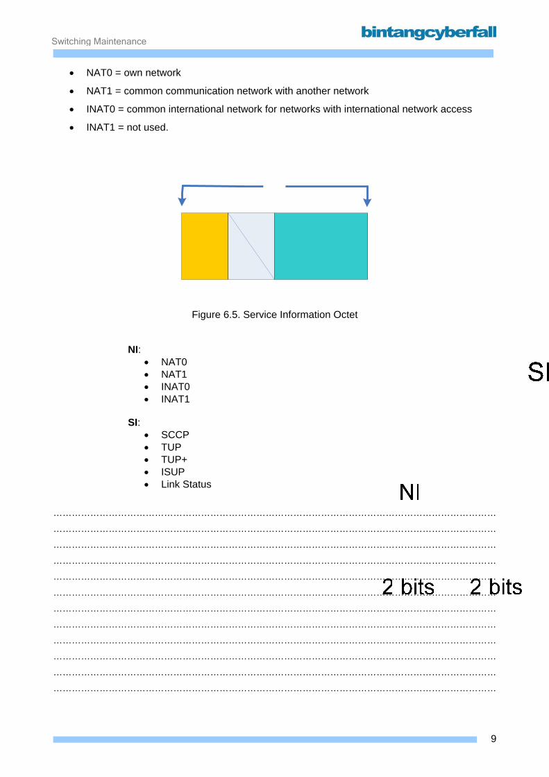
Switching Maintenance
• NAT0 = own network
• NAT1 = common communication network with another network
• INAT0 = common international network for networks with international network access
• INAT1 = not used.
Figure 6.5. Service Information Octet
NI: • NAT0 • NAT1 • INAT0 • INAT1
SI: • SCCP • TUP • TUP+ • ISUP • Link Status
………………………………………………………………………………………………………………………………
………………………………………………………………………………………………………………………………
………………………………………………………………………………………………………………………………
………………………………………………………………………………………………………………………………
………………………………………………………………………………………………………………………………
………………………………………………………………………………………………………………………………
………………………………………………………………………………………………………………………………
………………………………………………………………………………………………………………………………
………………………………………………………………………………………………………………………………
………………………………………………………………………………………………………………………………
………………………………………………………………………………………………………………………………
………………………………………………………………………………………………………………………………
9BCCN2200 © 2007 Bintang CyberFall
Switching Maintenance
Signaling information field (SIF) The signaling information field (SIF) only exists in message signal units. It contains the actual user
message.
Check bits (CK) The check bits (CK) are formed on the transmission side from the contents of the signal unit and
are added to the signal unit as redundancy.
Status field (SF) The status field (SF) only exists in link status signal units. It contains status indications for the
alignment of the transmit and receive directions.
10BCCN2200 © 2007 Bintang CyberFall
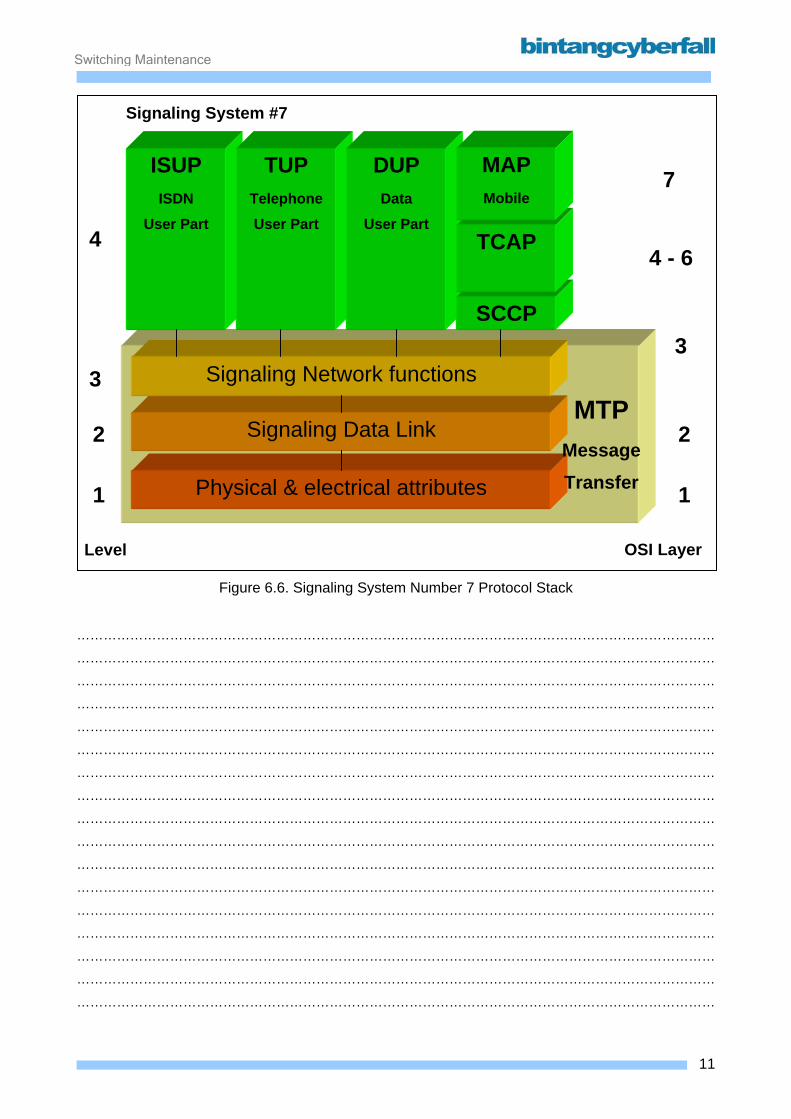
Switching Maintenance
Signaling System #7
Physical & electrical attributes
Signaling Data Link
Signaling Network functions
MTP Message Transfer
ISUP ISDN
User Part
TUP Telephone
User Part
DUP Data
User Part
SCCP
7
4 - 6
3
2
1
3
2
1
4
Level
TCAP
MAP Mobile
OSI Layer
Figure 6.6. Signaling System Number 7 Protocol Stack
………………………………………………………………………………………………………………………………
………………………………………………………………………………………………………………………………
………………………………………………………………………………………………………………………………
………………………………………………………………………………………………………………………………
………………………………………………………………………………………………………………………………
………………………………………………………………………………………………………………………………
………………………………………………………………………………………………………………………………
………………………………………………………………………………………………………………………………
………………………………………………………………………………………………………………………………
………………………………………………………………………………………………………………………………
………………………………………………………………………………………………………………………………
………………………………………………………………………………………………………………………………
………………………………………………………………………………………………………………………………
………………………………………………………………………………………………………………………………
………………………………………………………………………………………………………………………………
………………………………………………………………………………………………………………………………
………………………………………………………………………………………………………………………………
11BCCN2200 © 2007 Bintang CyberFall
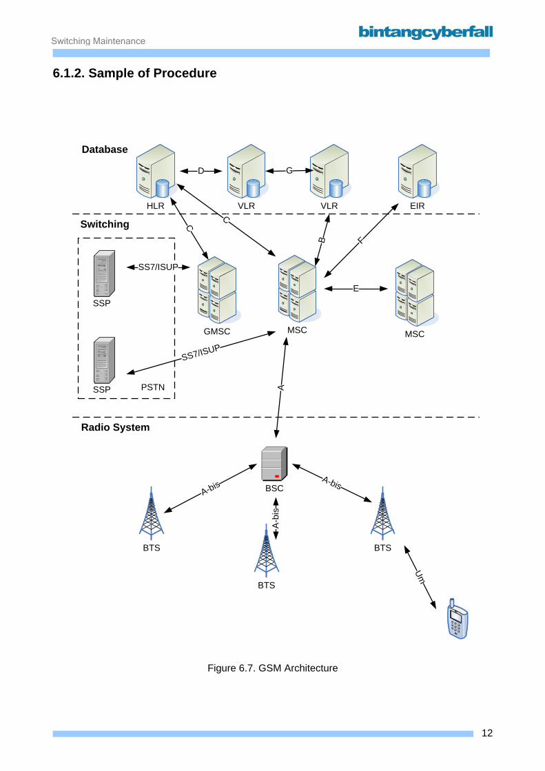
Switching Maintenance
6.1.2. Sample of Procedure
BTS
BSC
BTS
HLR VLR VLR EIR
SSP
SSP
GMSC MSCMSC
PSTN
BTS
A-bis
A-b
is
A-bis
Um
SS7/ISUP
SS7/ISUP
E
D G
C
C
B F
A
Database
Switching
Radio System
Figure 6.7. GSM Architecture
12BCCN2200 © 2007 Bintang CyberFall
Switching Maintenance
Location Registration / Location Update Information of the current location of a mobile subscriber are necessary to built up a connection to
the subscriber, i.e. to start a Mobile Terminating Call MTC. To keep track of the users current
location the Location Registration / Update procedures are used. Always the MS is responsible to
initiate this Location Registration / Update procedures. It informs the network on its current
Location Area. The Location Area information is stored in the currently responsible VLR. The
identity of this VLR is stored in the users HLR.
If a MS is "new" in a PLMN a Location Registration is performed. "New" is defined as the very first
usage of a SIM card or a first access after changing the PLMN.
In case of a Location Registration the network needs the IMSI of the MS, because either no TMSI
has been allocated before to the MS (in case of first SIM usage) or it is impossible to regenerate
the IMSI from the TMSI, because the new VLR is not able to get into contact with the old VLR (e.g.
in case of PLMN changes). After Location Registration, in the following Location Updates are used
to update the location information in the PLMN. In a Location Update only the TMSI is transmitted
via Um.
There are three reasons to perform a Location Update Procedure LUP:
Location Update with "IMSI Attach": If a MS is switched on / off, the network is informed about
the change of the current MS state, i.e. whether to be reachable or not. Therefore, when being
switched on / off, the MS performs an "IMSI Attach" / "IMSI Detach" procedure. The information
whether the MS is Attached / Detached is stored in the VLR. If an "IMSI Attach is performed it is
connected with a LUP.
Normal Location Update: Normally a LUP is performed after the MS has recognized that it has
crossed the boarder between two different Location Areas.
The MS is able to recognize the LA change, because it always listens around to the broadcast
information of all cells in its environment, which include the CGI (and so the LAI). If the LAI of the
strongest cell changes, a LUP is performed.
Periodical Location Update: A periodic LUP is initiated by a MS at regular intervals. If the VLR
does not receive the LUP after a certain time, a "Mobile Station not reachable" flag is set.
The LUP is not performed during the duration of a connection. In this case, the LUP is performed
after call release.
13BCCN2200 © 2007 Bintang CyberFall
Switching Maintenance
Location Update Procedure LUP without change of the MSC area
1. The MS recognizes that the LAI has changed. It requests a LUP, identifying itself with the
TMSI or IMSI. The request and the identity are forwarded to the VLR.
2. The VLR re-identifies the IMSI from the TMSI. If no / no more Triples are available in the
VLR, it requests triples from the AC via the HLR.
3. The AC generates a set of Triples and delivers them via HLR to the VLR.
4. The VLR stores the Triples and initiates the Authentication, then gives the cipher start
command and initiates an IMEI check (optional).
5. If the Authentication, cipher start and IMEI check are successful, the VLR needs for call
setups the subscriber data. In case of a LR, they are have not been stored before in the
VLR and so they have to be requested from the HLR. Together with this request, the VLR
delivers its identity and the information, where this subscriber is stored in the VLR, i.e. the
Local Mobile Subscriber
1. Identity, to the VLR.
6. The HLR stores the VLR identity and LMSI and transmits the requested subscriber data to
the VLR.
7. The VLR stores the subscriber data and assigns a TMSI (LR: mandatory) or a new TMSI
(LUP: only with MSC/VLR change) to the MS. This TMSI is transmitted together with the
VLRs acknowledgement, that the LUP has been successful, to the MS. There, the new
TMSI and LAI are stored on the SIM card.
14BCCN2200 © 2007 Bintang CyberFall
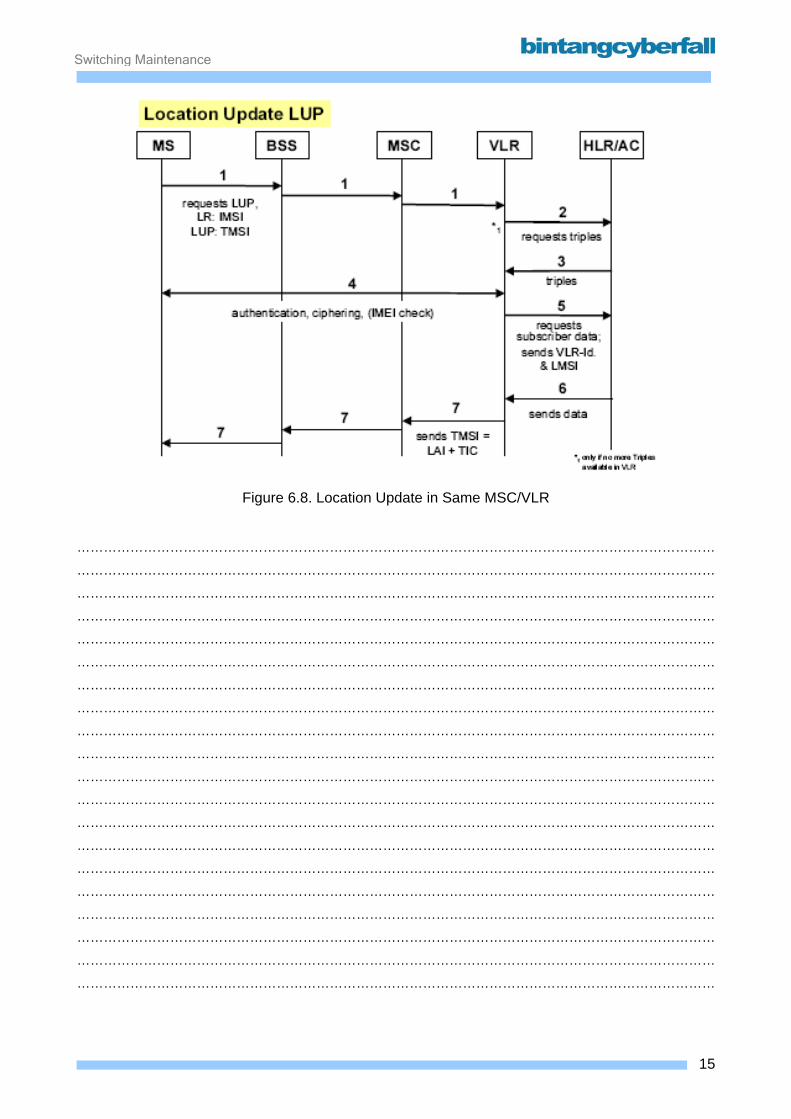
Switching Maintenance
Figure 6.8. Location Update in Same MSC/VLR
………………………………………………………………………………………………………………………………
………………………………………………………………………………………………………………………………
………………………………………………………………………………………………………………………………
………………………………………………………………………………………………………………………………
………………………………………………………………………………………………………………………………
………………………………………………………………………………………………………………………………
………………………………………………………………………………………………………………………………
………………………………………………………………………………………………………………………………
………………………………………………………………………………………………………………………………
………………………………………………………………………………………………………………………………
………………………………………………………………………………………………………………………………
………………………………………………………………………………………………………………………………
………………………………………………………………………………………………………………………………
………………………………………………………………………………………………………………………………
………………………………………………………………………………………………………………………………
………………………………………………………………………………………………………………………………
………………………………………………………………………………………………………………………………
………………………………………………………………………………………………………………………………
………………………………………………………………………………………………………………………………
………………………………………………………………………………………………………………………………
15BCCN2200 © 2007 Bintang CyberFall
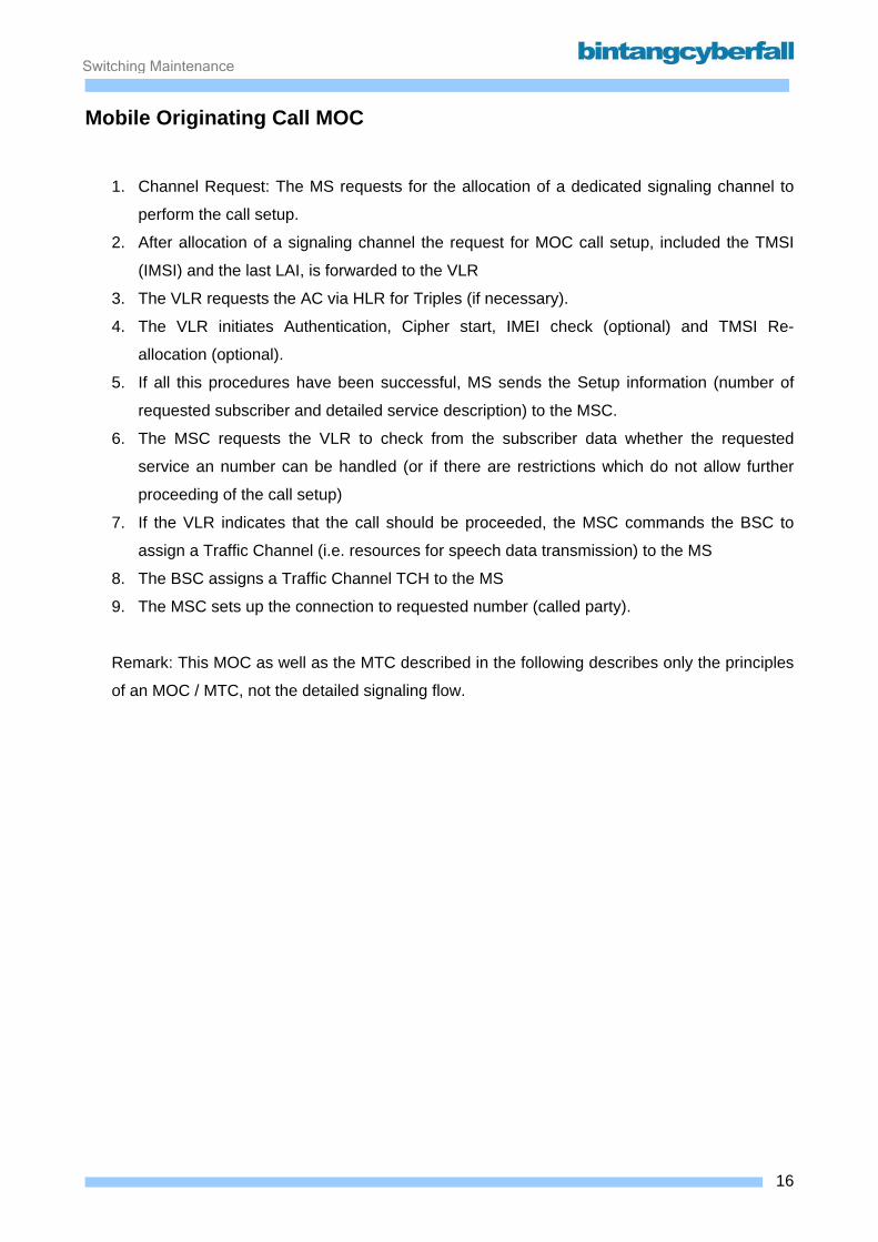
Switching Maintenance
Mobile Originating Call MOC
1. Channel Request: The MS requests for the allocation of a dedicated signaling channel to
perform the call setup.
2. After allocation of a signaling channel the request for MOC call setup, included the TMSI
(IMSI) and the last LAI, is forwarded to the VLR
3. The VLR requests the AC via HLR for Triples (if necessary).
4. The VLR initiates Authentication, Cipher start, IMEI check (optional) and TMSI Re-
allocation (optional).
5. If all this procedures have been successful, MS sends the Setup information (number of
requested subscriber and detailed service description) to the MSC.
6. The MSC requests the VLR to check from the subscriber data whether the requested
service an number can be handled (or if there are restrictions which do not allow further
proceeding of the call setup)
7. If the VLR indicates that the call should be proceeded, the MSC commands the BSC to
assign a Traffic Channel (i.e. resources for speech data transmission) to the MS
8. The BSC assigns a Traffic Channel TCH to the MS
9. The MSC sets up the connection to requested number (called party).
Remark: This MOC as well as the MTC described in the following describes only the principles
of an MOC / MTC, not the detailed signaling flow.
16BCCN2200 © 2007 Bintang CyberFall
Switching Maintenance
Figure 6.9. Mobile Originating Call
………………………………………………………………………………………………………………………………
………………………………………………………………………………………………………………………………
………………………………………………………………………………………………………………………………
………………………………………………………………………………………………………………………………
………………………………………………………………………………………………………………………………
………………………………………………………………………………………………………………………………
………………………………………………………………………………………………………………………………
………………………………………………………………………………………………………………………………
………………………………………………………………………………………………………………………………
………………………………………………………………………………………………………………………………
………………………………………………………………………………………………………………………………
………………………………………………………………………………………………………………………………
………………………………………………………………………………………………………………………………
………………………………………………………………………………………………………………………………
………………………………………………………………………………………………………………………………
………………………………………………………………………………………………………………………………
………………………………………………………………………………………………………………………………
………………………………………………………………………………………………………………………………
………………………………………………………………………………………………………………………………
………………………………………………………………………………………………………………………………
………………………………………………………………………………………………………………………………
………………………………………………………………………………………………………………………………
17BCCN2200 © 2007 Bintang CyberFall

Switching Maintenance
6.2. Signaling Component
18BCCN2200 © 2007 Bintang CyberFall
Switching Maintenance
6.2.1. Function
To control the SS7 signaling system, the Signaling System Network Controller (SSNC) is used in
D900. It provides the protocol functions of the message transfer part (MTP) and parts of the
signaling connection control part (SCCP). The open architecture of the SSNC is based on Solution
O.N.E (optimized network evolution) technology, i.e. message transfer within the SSNC is based
on ATM.
Connection to the CP113 is done via a CP processor, the AMP. The signaling channels are
supplied by means of PCM30/24 via LTGs or directly by the network.
Communication with users in the LTGs is provided directly via high-speed interfaces over the
MBD.
The SSNC has its own OAM platform "Switch Commander". For operation, it is provided with
V24/LAN interfaces for the connection of NM systems.
Thanks to its own OAM platform, the SSNC can also be used as a standalone network element
(i.e. without D900 environment).
This document only describes the functionality of the SSNC as signaling network controller. It does
not describe special signaling interfaces like the signaling on the Iu interface for UMTS or on the
Gb interface for GPRS. These interfaces are discussed in the corresponding UMTS and GPRS
courses.
The SSNC implements the functions of the message transfer part MTP and parts of the SCCP
(SCCP global title translation and SCCP management). This is shown in the following diagram,
using a protocol stack.
Signaling System No.7 is divided into two main parts so that it can be adapted optimally to the
diverse requirements of its various users:
• The message transfer part MTP and the
• User parts UP.
Message Transfer Part The message transfer part (MTP) is used in CCS7 by all user parts as a transport system for
message exchange. Messages to be transferred from one user part to another are given to the
message transfer part which ensures that the messages reach the addressed user part in the
correct order, without information loss, duplication or sequence alteration and without any bit
errors.
19BCCN2200 © 2007 Bintang CyberFall
Switching Maintenance
Functional levels of the MTP Level 1 defines the physical, electrical and functional characteristics of a signaling data link and
the access units. Level 1 represents the bearer for a signaling link. In a digital network, 64-kbit/s
channels are generally used as signaling data links.
Level 2 defines the functions and procedures for a correct exchange of user messages via a
signaling link. The following tasks must be carried out in level 2:
• delimitation of the signal units by flags and elimination of superfluous flags
• error detection using check bits and error correction by retransmitting signal units
• restoration of fault-free operation, e.g. after disruption of the signaling data link.
Level 3 defines the interworking of the individual signaling links. A distinction is made between the
two following functional areas:
• message routing and message distribution
• signaling network management
In the SSNC these functional levels are mapped on the functional units MP:SLT (signaling link
terminal) and MP:SM (signaling manager). The MP:SLT performs MTP-level 1 (message transfer),
MTP-level 2 (error correction) and MTP-level 3 (message handling incl. allocation). These SLT
functions are logically combined and are performed by one or more MPs. Depending on system
usage of the network node, the SSNC can be provided with up to 47 MP:SLT. Per SLT up to 60
signaling channels (64kbit/s) may be connected, but not more than 1500 links in total!
The MP:SM functional unit supports MTP-Level 3 network management and hosts the routing
database for the signaling network. Thus, each MP:SLT has an internal connection to the MP:SM.
User Parts The function, structure, format and coding of the messages as well as the connection sequences
and the procedures for cooperating with other signaling systems (interworking) are stipulated in
the user parts. The user parts therefore control the setup and release of circuit connections, the
handling of service features as well as administration and maintenance functions for the signaling
channels (SCCP management). The ISDN- and telephone user parts (ISUP/TUP) are located in
the LTGs. The SCCP is located in the SSNC and is the only user part in case the SSNC is
operated as Signaling Relay Point (SRP).
20BCCN2200 © 2007 Bintang CyberFall
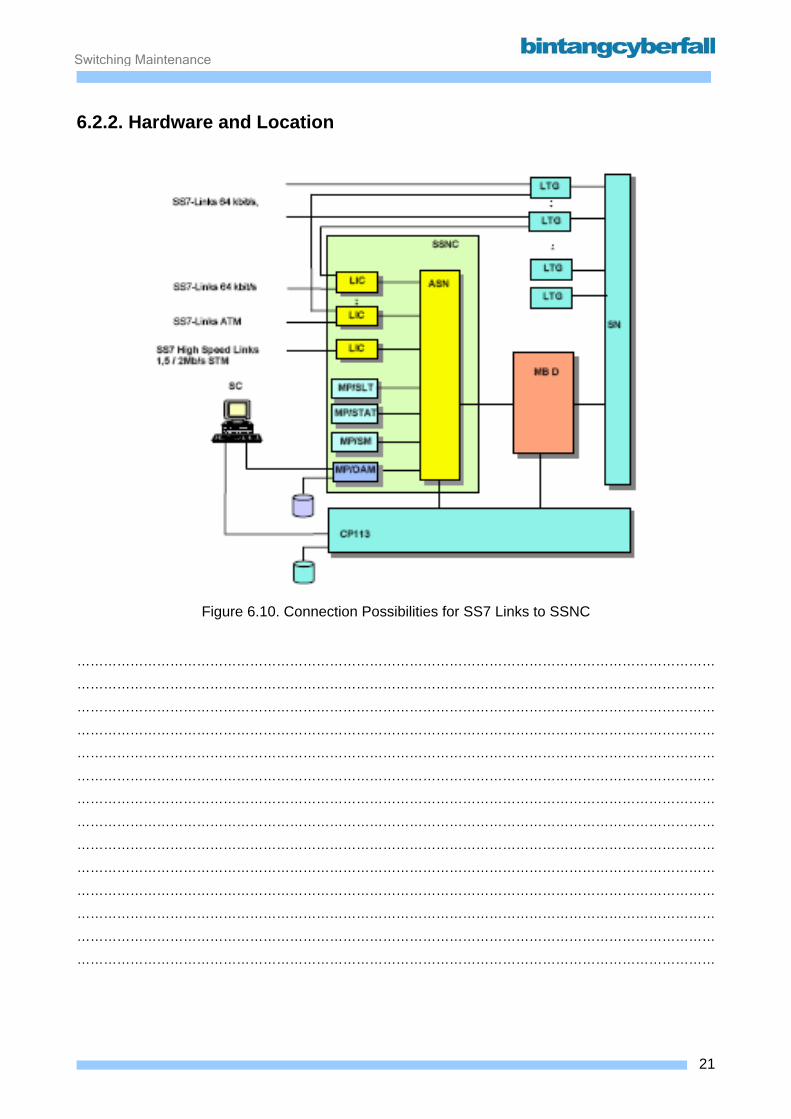
Switching Maintenance
6.2.2. Hardware and Location
Figure 6.10. Connection Possibilities for SS7 Links to SSNC
………………………………………………………………………………………………………………………………
………………………………………………………………………………………………………………………………
………………………………………………………………………………………………………………………………
………………………………………………………………………………………………………………………………
………………………………………………………………………………………………………………………………
………………………………………………………………………………………………………………………………
………………………………………………………………………………………………………………………………
………………………………………………………………………………………………………………………………
………………………………………………………………………………………………………………………………
………………………………………………………………………………………………………………………………
………………………………………………………………………………………………………………………………
………………………………………………………………………………………………………………………………
………………………………………………………………………………………………………………………………
………………………………………………………………………………………………………………………………
21BCCN2200 © 2007 Bintang CyberFall
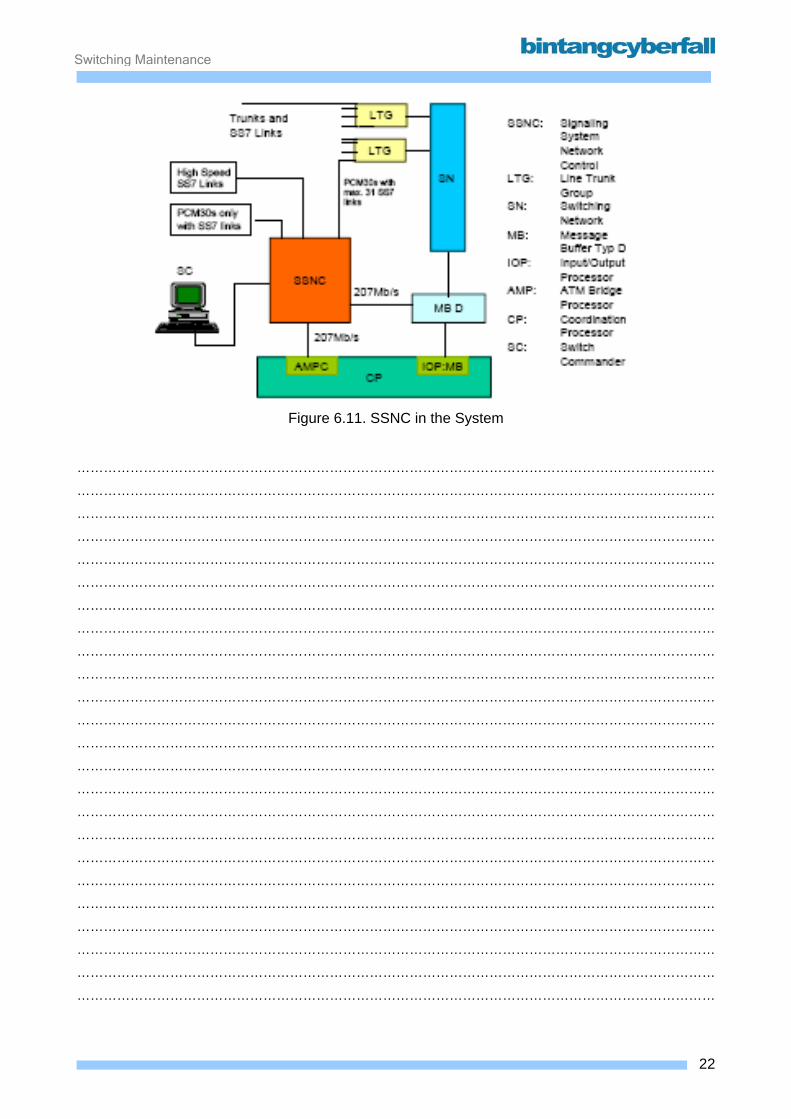
Switching Maintenance
Figure 6.11. SSNC in the System
………………………………………………………………………………………………………………………………
………………………………………………………………………………………………………………………………
………………………………………………………………………………………………………………………………
………………………………………………………………………………………………………………………………
………………………………………………………………………………………………………………………………
………………………………………………………………………………………………………………………………
………………………………………………………………………………………………………………………………
………………………………………………………………………………………………………………………………
………………………………………………………………………………………………………………………………
………………………………………………………………………………………………………………………………
………………………………………………………………………………………………………………………………
………………………………………………………………………………………………………………………………
………………………………………………………………………………………………………………………………
………………………………………………………………………………………………………………………………
………………………………………………………………………………………………………………………………
………………………………………………………………………………………………………………………………
………………………………………………………………………………………………………………………………
………………………………………………………………………………………………………………………………
………………………………………………………………………………………………………………………………
………………………………………………………………………………………………………………………………
………………………………………………………………………………………………………………………………
………………………………………………………………………………………………………………………………
………………………………………………………………………………………………………………………………
………………………………………………………………………………………………………………………………
22BCCN2200 © 2007 Bintang CyberFall
Switching Maintenance
The SSNC consists of a number of main processors (MPs) which perform various functions for
processing signaling messages and other tasks. The MPs are connected by an ATM switching
network (ASN) which can link up to 50 MPs based on the same hardware platform. The interface
to signaling links is provided by Line Interface Cards (LICs) shown in the diagram on the following
page.
The SSNC has standard ATM connections (optical fiber) with the D900 components MB and CP,
and 2Mbit/s PCM30 to the LTGs or to other network nodes.
Main Processor MP: The Main Processor (MP) is the central component of the SSNC.
Each MP-function consists of 2 HW-modules MPUC or MPUD (for redundancy reasons).
In general there are 2 types of MP:
1. MP:SA (main processor with standalone capabilities) used as MP:OAM and MP:OAMD. The
MP:OAM performs safeguarding functions, connects the external memories (MDD and MOD) and
the Ethernet interface to the SC.
The optional MP:OAMD also has an external harddisk (but no MOD) and an Ethernet interface.
This processor is responsible for handling charging data.
The MP:OAM is additionally equipped with an ALIB for stand-alone configurations. The ALIB
makes it possible to display the alarm status or generate audible alarms in the rack and via
operator devices. In the opposite direction, events in the environment (e.g. fire, flooding, and door
contacts) can be detected via contact loops and reported centrally to the operator.
2. MP:AP (main processor used for application SW processing)
In the MP:AP different software functions can be performed. The loaded SW is depending of the
application. The following types are usual (but some mixed versions are also existing):
• One MP:SM for all signaling management functions e.g. link testing, LSSUs
• One MP:STATS for SS7 traffic measurement, if used
• MP:SLTs to process the L2 and L3 tasks (Message Transfer Part). Each pair of
MPUCs can handle up to 60 SS7 signaling links (64kbps) or 2 High-Speed-Links
(2 Mbps). If MPUD is used each pair may connect up to 127 SS7 links or 4 HSL.
• MP:GTTs if Global Title Translation is performed (e.g. VLR,HLR,SRP)
• (MP:NP if the number portability feature of the SSNC is used)
23BCCN2200 © 2007 Bintang CyberFall
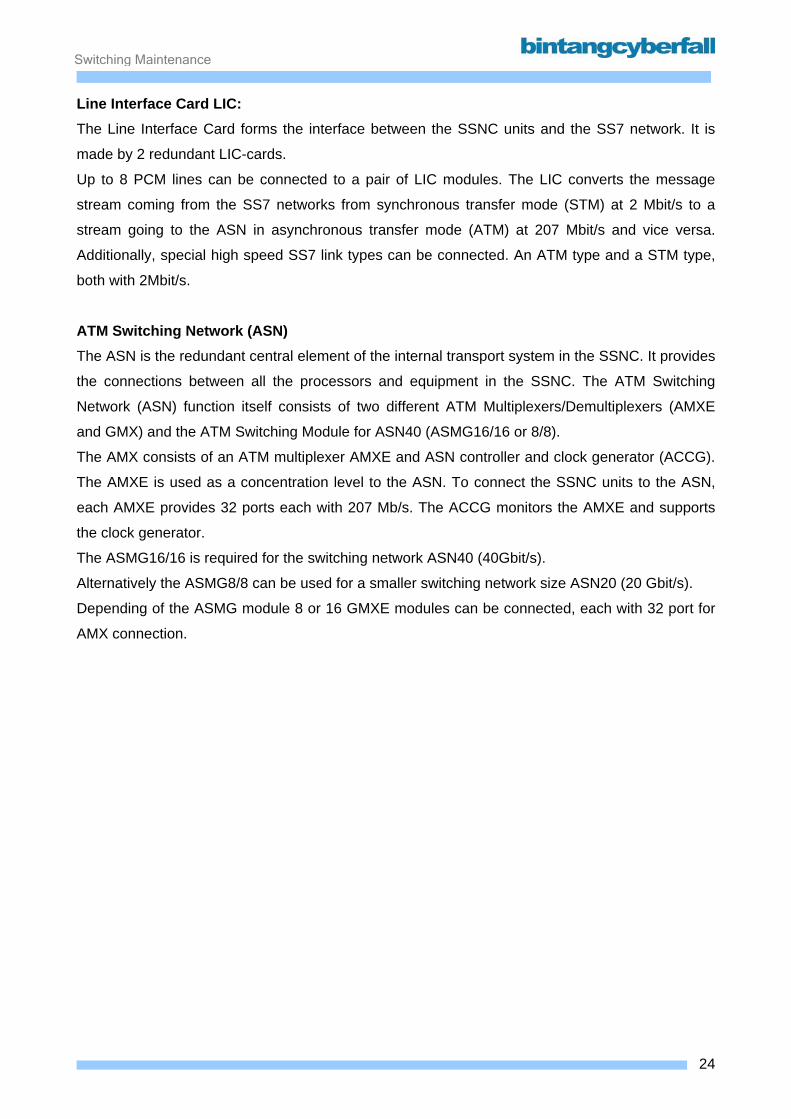
Switching Maintenance
Line Interface Card LIC: The Line Interface Card forms the interface between the SSNC units and the SS7 network. It is
made by 2 redundant LIC-cards.
Up to 8 PCM lines can be connected to a pair of LIC modules. The LIC converts the message
stream coming from the SS7 networks from synchronous transfer mode (STM) at 2 Mbit/s to a
stream going to the ASN in asynchronous transfer mode (ATM) at 207 Mbit/s and vice versa.
Additionally, special high speed SS7 link types can be connected. An ATM type and a STM type,
both with 2Mbit/s.
ATM Switching Network (ASN) The ASN is the redundant central element of the internal transport system in the SSNC. It provides
the connections between all the processors and equipment in the SSNC. The ATM Switching
Network (ASN) function itself consists of two different ATM Multiplexers/Demultiplexers (AMXE
and GMX) and the ATM Switching Module for ASN40 (ASMG16/16 or 8/8).
The AMX consists of an ATM multiplexer AMXE and ASN controller and clock generator (ACCG).
The AMXE is used as a concentration level to the ASN. To connect the SSNC units to the ASN,
each AMXE provides 32 ports each with 207 Mb/s. The ACCG monitors the AMXE and supports
the clock generator.
The ASMG16/16 is required for the switching network ASN40 (40Gbit/s).
Alternatively the ASMG8/8 can be used for a smaller switching network size ASN20 (20 Gbit/s).
Depending of the ASMG module 8 or 16 GMXE modules can be connected, each with 32 port for
AMX connection.
24BCCN2200 © 2007 Bintang CyberFall
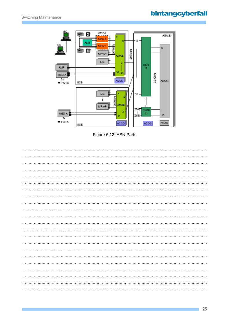
Switching Maintenance
Figure 6.12. ASN Parts
………………………………………………………………………………………………………………………………
………………………………………………………………………………………………………………………………
………………………………………………………………………………………………………………………………
………………………………………………………………………………………………………………………………
………………………………………………………………………………………………………………………………
………………………………………………………………………………………………………………………………
………………………………………………………………………………………………………………………………
………………………………………………………………………………………………………………………………
………………………………………………………………………………………………………………………………
………………………………………………………………………………………………………………………………
………………………………………………………………………………………………………………………………
………………………………………………………………………………………………………………………………
………………………………………………………………………………………………………………………………
………………………………………………………………………………………………………………………………
………………………………………………………………………………………………………………………………
………………………………………………………………………………………………………………………………
………………………………………………………………………………………………………………………………
………………………………………………………………………………………………………………………………
………………………………………………………………………………………………………………………………
………………………………………………………………………………………………………………………………
………………………………………………………………………………………………………………………………
………………………………………………………………………………………………………………………………
25BCCN2200 © 2007 Bintang CyberFall

Switching Maintenance
Frame and rack layout The SSNC has 4 different shelf-types (HW-frames)
1. SCB: Basic Shelf
2. SCE: Extension Shelf
3. ASN: ATM Switching Network or ASN(H)
4. SXCB: For MP:OAMD (Charging Processor)
SCB The Basic Shelf contains the minimum HW needed for SSNC-operation:
The MP: OAM (MP:SA) with SC-connection, the external memories (MDDs, MODs), the MP:SM,
one pair of LICs and the AMXEs/ACCGs for supervision, synchronization and ASN connection
(both sides). With some modifications (e.g. no MOD is used), this shelf type can be used for a
MP:OAMD too.
SCE Up to 7 SCE shelves in max. 3 racks can be used, depending on how many MPs/LICs are used. It
contains a maximum of 8 MP- or LIC-pairs and the AMXEs/ACCGs for supervision,
synchronization and ASN connection (both sides).
ASN Contains the HW-modules for the ATM switching network.
Two different versions are existing:
• ASN 0/1 also called ASN(40) or ASN(E) where the different sides of the ASN are in 2
different shelves or
• ASN(H) also called ASN(20) or "compact ASN" where both ASN-sides are in the same
shelf. Due to this a second SCE is possible in the rack. Another type of ASMG may be
used.
SXCB The F:SXCB can be used for the MP:OAMD for charging purposes only and is located on MUT07
of the basic rack, or on MUT09 of an extension rack. It is not allowed to install the F:SXCB for the
MP-OAMD on any other position.
An Extension Rack is not shown in the following pictures. It is only used for SCE or
SXCB shelf types.
26BCCN2200 © 2007 Bintang CyberFall

Switching Maintenance
Figure 6.13. ASN40 Rack
………………………………………………………………………………………………………………………………
………………………………………………………………………………………………………………………………
………………………………………………………………………………………………………………………………
………………………………………………………………………………………………………………………………
………………………………………………………………………………………………………………………………
………………………………………………………………………………………………………………………………
………………………………………………………………………………………………………………………………
………………………………………………………………………………………………………………………………
………………………………………………………………………………………………………………………………
………………………………………………………………………………………………………………………………
………………………………………………………………………………………………………………………………
………………………………………………………………………………………………………………………………
………………………………………………………………………………………………………………………………
………………………………………………………………………………………………………………………………
………………………………………………………………………………………………………………………………
………………………………………………………………………………………………………………………………
………………………………………………………………………………………………………………………………
………………………………………………………………………………………………………………………………
27BCCN2200 © 2007 Bintang CyberFall
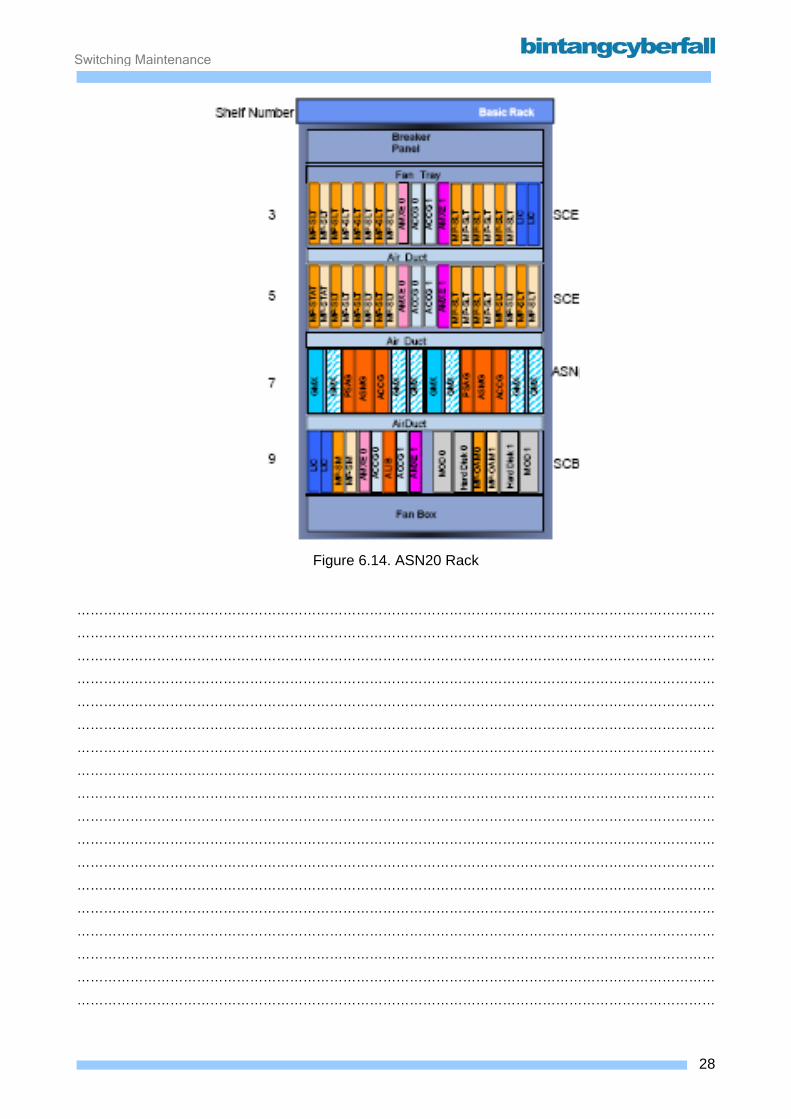
Switching Maintenance
Figure 6.14. ASN20 Rack
………………………………………………………………………………………………………………………………
………………………………………………………………………………………………………………………………
………………………………………………………………………………………………………………………………
………………………………………………………………………………………………………………………………
………………………………………………………………………………………………………………………………
………………………………………………………………………………………………………………………………
………………………………………………………………………………………………………………………………
………………………………………………………………………………………………………………………………
………………………………………………………………………………………………………………………………
………………………………………………………………………………………………………………………………
………………………………………………………………………………………………………………………………
………………………………………………………………………………………………………………………………
………………………………………………………………………………………………………………………………
………………………………………………………………………………………………………………………………
………………………………………………………………………………………………………………………………
………………………………………………………………………………………………………………………………
………………………………………………………………………………………………………………………………
………………………………………………………………………………………………………………………………
28BCCN2200 © 2007 Bintang CyberFall