Embed Size (px)
Citation preview
Switched Storage Architecture Benefits
Computer Measurements Group
November 14th, 2002
Yves Coderre
Evolution of Technology
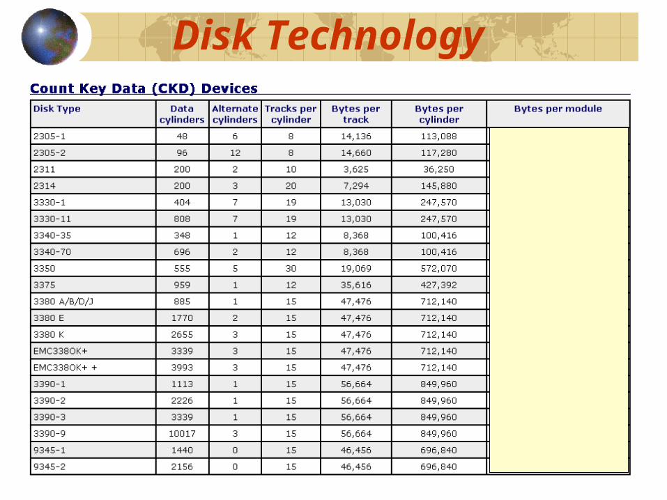
Disk Technology
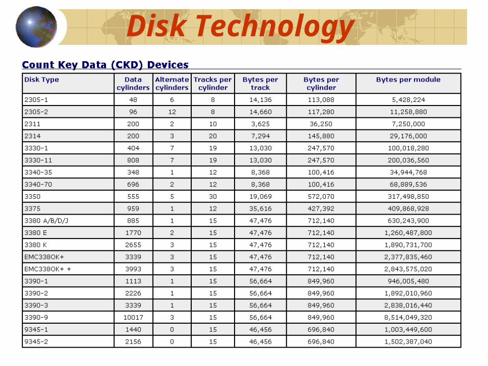
Disk Technology
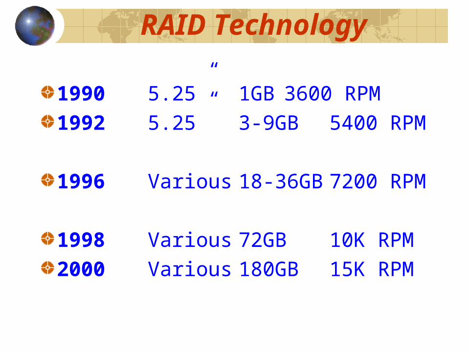
RAID Technology
1990 5.25” 1GB 3600 RPM1992 5.25” 3-9GB 5400 RPM
1996 Various 18-36GB7200 RPM
1998 Various 72GB 10K RPM2000 Various 180GB 15K RPM
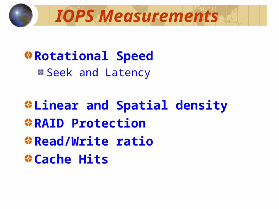
IOPS Measurements
Rotational SpeedSeek and Latency
Linear and Spatial densityRAID ProtectionRead/Write ratioCache Hits
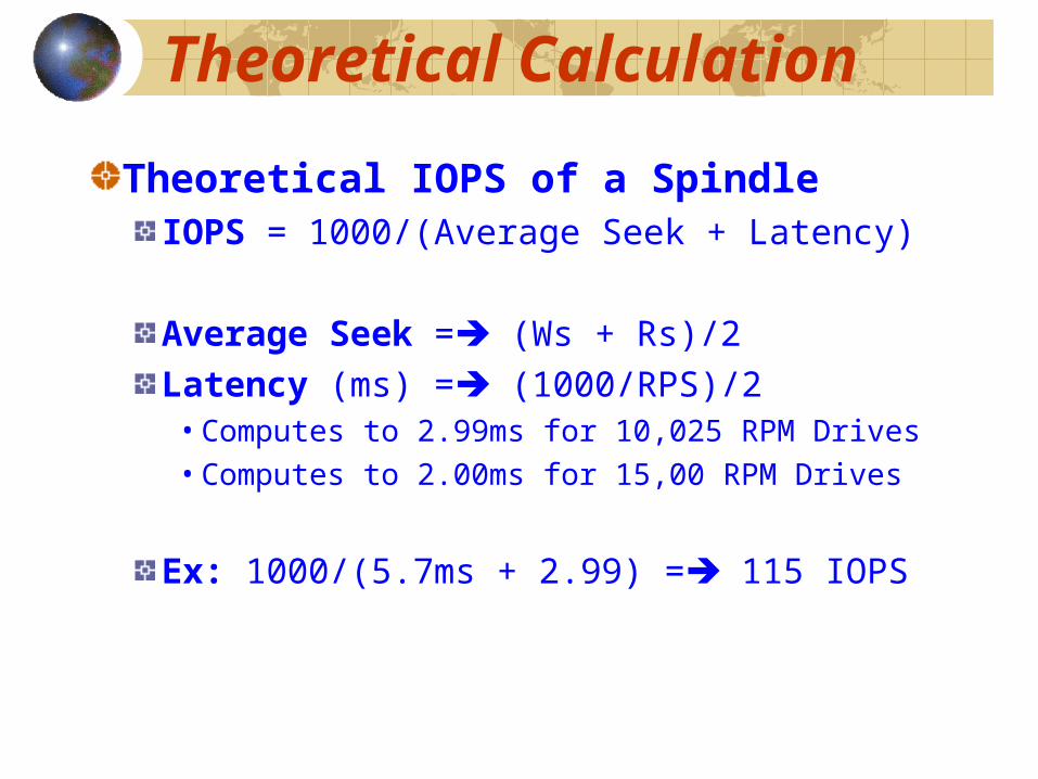
Theoretical Calculation
Theoretical IOPS of a SpindleIOPS = 1000/(Average Seek + Latency)
Average Seek = (Ws + Rs)/2Latency (ms) = (1000/RPS)/2 • Computes to 2.99ms for 10,025 RPM Drives• Computes to 2.00ms for 15,00 RPM Drives
Ex: 1000/(5.7ms + 2.99) = 115 IOPS
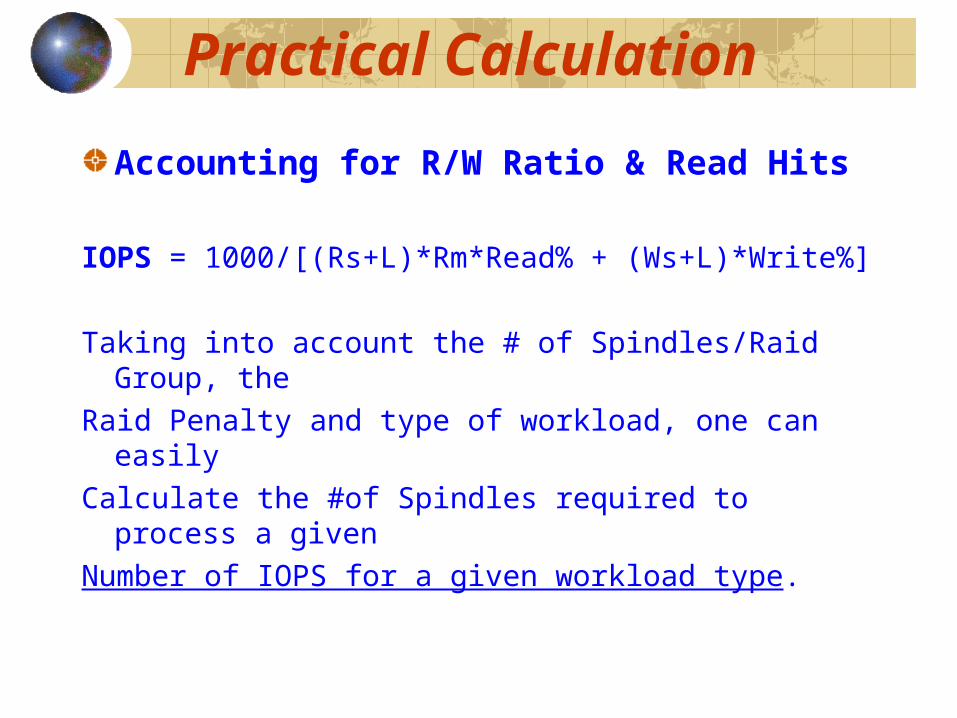
Practical Calculation
Accounting for R/W Ratio & Read Hits
IOPS = 1000/[(Rs+L)*Rm*Read% + (Ws+L)*Write%]
Taking into account the # of Spindles/Raid Group, theRaid Penalty and type of workload, one can easilyCalculate the #of Spindles required to process a givenNumber of IOPS for a given workload type.

Sample Calculation
10,000 IOPS, 3/1 R/W Ratio @ 70% Read Hits,
100% Spindle Busy
10K RPM Drives (Rd Seek 5.2ms, Wr Seek 6.0ms)RAID 5 (3+1): 16 Array Groups (64 Drives)
RAID 1 (2+2): 13 Array Groups (52 Drives)

Sample Calculation
10,000 IOPS, 3/1 R/W Ratio @ 70% Read Hits,
100% Spindle Busy
10K RPM Drives (Rd Seek 5.2ms, Wr Seek 6.0ms)RAID 5 (3+1): 16 Array Groups (64 Drives)
RAID 1 (2+2): 13 Array Groups (52 Drives)
15K RPM Drives (Rd Seek 3.9ms, Wr Seek 4.5ms)RAID 5 (3+1): 11 Array Groups (44 Drives)
RAID 1 (2+2): 10 Array Groups (40 Drives)

Channel Technology
1990 Block Mux 3-4.5 MB/Sec1993 ESCON 17 MB/Sec

Channel Technology
1990 Block Mux 3-4.5 MB/Sec1993 ESCON 17 MB/Sec
1996 Fibre Channel 100 MB/Sec1998 Fibre Channel 200 MB/Sec

Channel Technology
1990 Block Mux 3-4.5 MB/Sec1993 ESCON 17 MB/Sec
1996 Fibre Channel 100 MB/Sec1998 Fibre Channel 200 MB/Sec
2000 FICON 100 MB/Sec2002 FICON 200 MB/Sec

Channel Connectivity
1990 16 BMUX 72 MB/Sec1993 16 ESCON 272 MB/Sec
Channel Connectivity
1990 16 BMUX 72 MB/Sec1993 16 ESCON 272 MB/Sec
1995 32 ESCON 544 MB/Sec1996 32 Fibre 3.2 GB/Sec
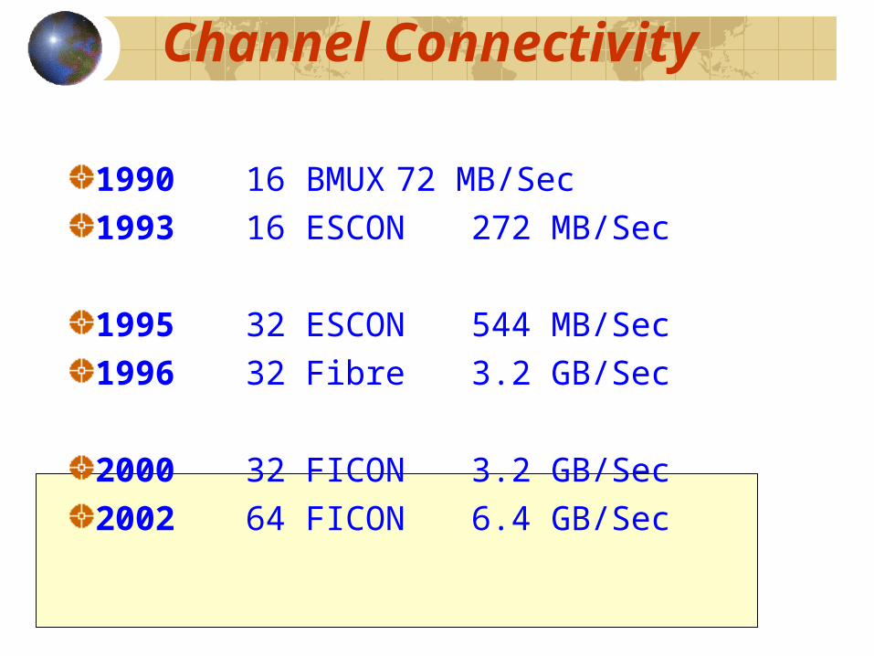
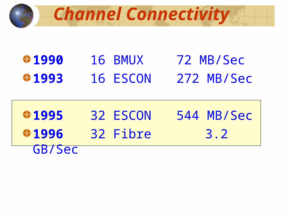
Channel Connectivity
1990 16 BMUX 72 MB/Sec1993 16 ESCON 272 MB/Sec
1995 32 ESCON 544 MB/Sec1996 32 Fibre 3.2 GB/Sec
2000 32 FICON 3.2 GB/Sec2002 64 FICON 6.4 GB/Sec
Disk Subsystems
1990 3880, 3990 with Attached Disk1991 ICDA Technology 4GB-32GB
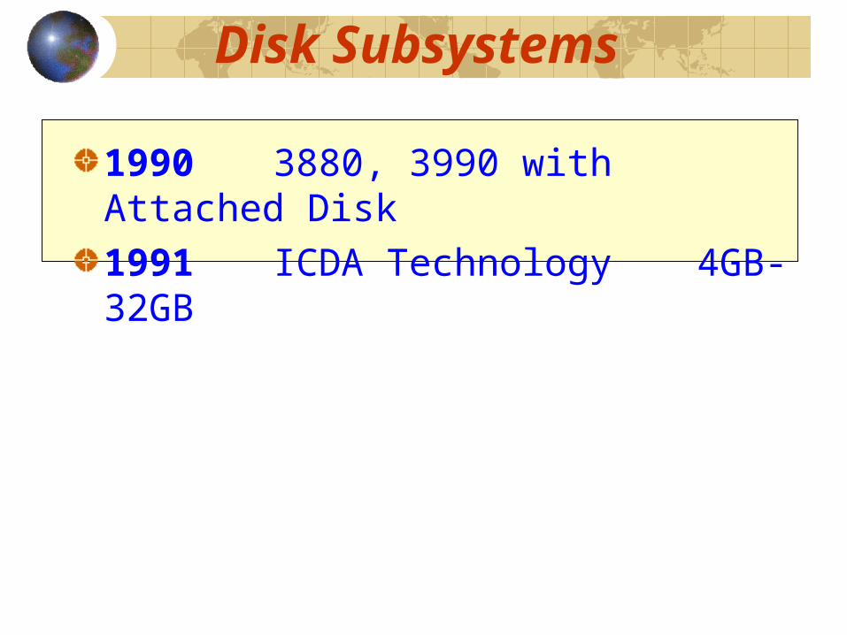
Disk Subsystems
1990 3880, 3990 with Attached Disk1991 ICDA Technology 4GB-32GB
1993 ICDA 512GB1995 ICDA 1TB

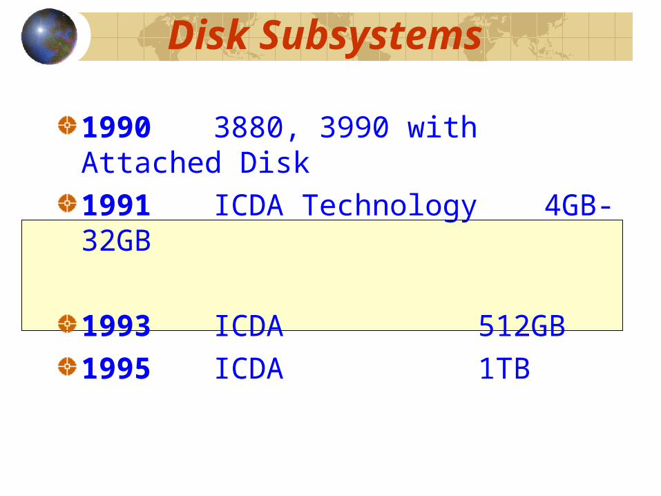
Disk Subsystems
1990 3880, 3990 with Attached Disk1991 ICDA Technology 4GB-32GB
1993 ICDA 512GB1995 ICDA 1TB
1997 RAID Subsystems 5TB2000 RAID Subsystems 75TB
IO Intensity Factors
Disk Technology5 MB to 180 GB Capacity3600 to 15,000 RPM
RAID Technology5.25” to 3.5” to 1” (1GB to 180GB)
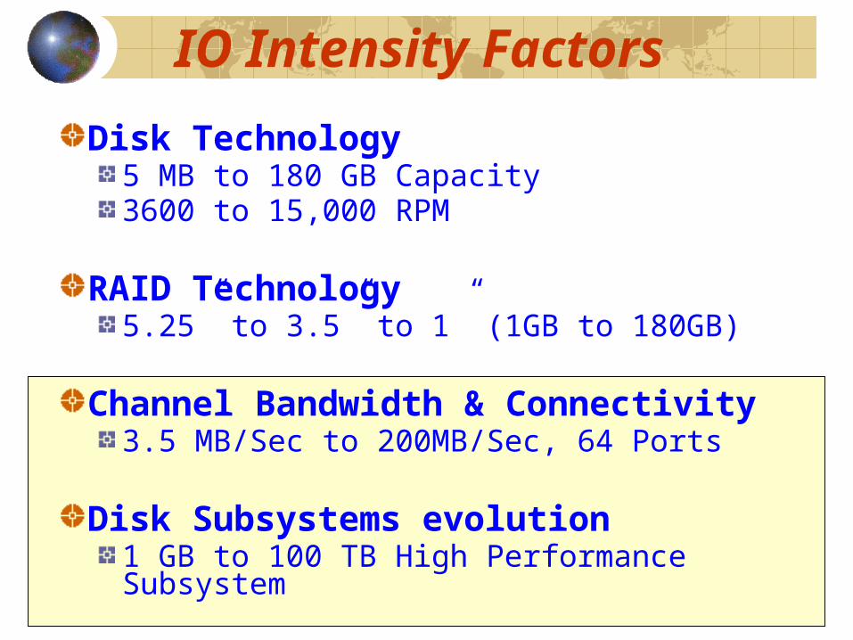
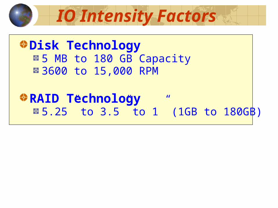
IO Intensity Factors
Disk Technology5 MB to 180 GB Capacity3600 to 15,000 RPM
RAID Technology5.25” to 3.5” to 1” (1GB to 180GB)
Channel Bandwidth & Connectivity3.5 MB/Sec to 200MB/Sec, 64 Ports
Disk Subsystems evolution1 GB to 100 TB High Performance Subsystem
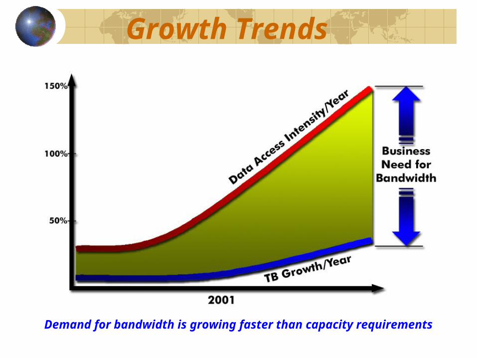
Growth Trends
Demand for bandwidth is growing faster than capacity requirements
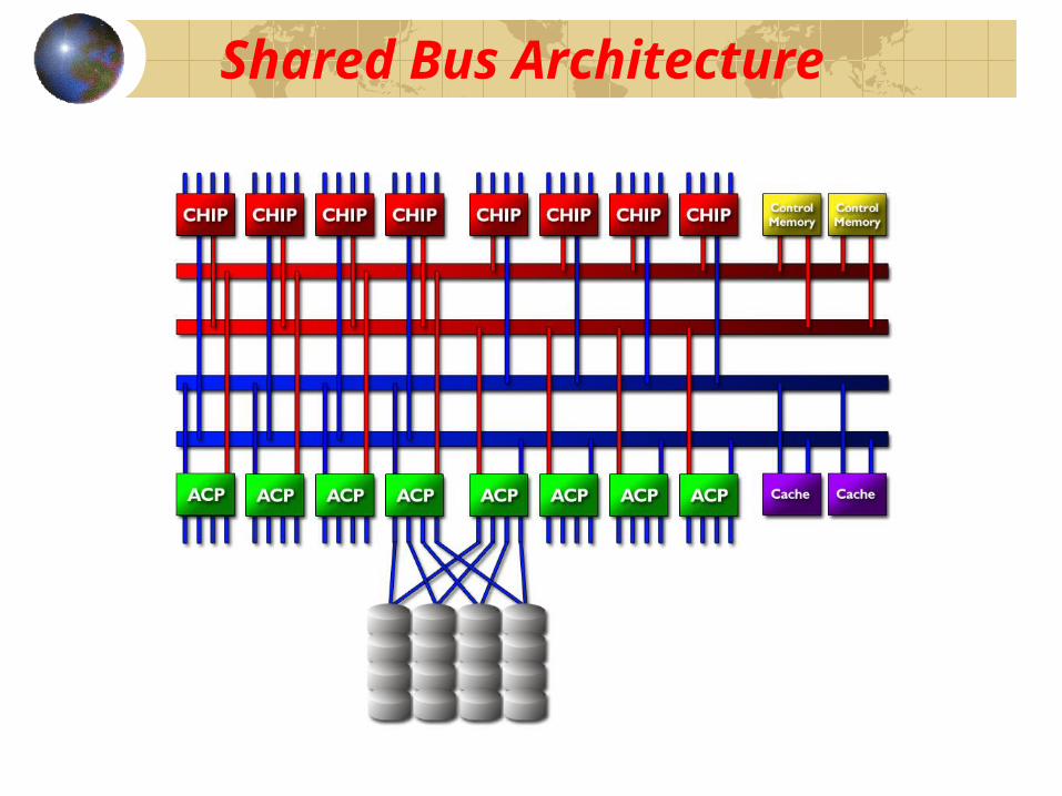
Shared Bus Architecture

Switch Architecture 2000
“(…) the most innovative technology), which built a SAN rather than a backbone bus into its Storage Sub-Systems to deliver exceptional performance and capacity flexibility.”
Bob Zimmerman , Giga Group
“The company’s new Switch Architecture further demonstrated their commitment to technological innovation and business-enabling solutions, and redefines the industry standard, once again.”
Jack Scott, Evaluator Group, Inc.

Switched Fabric Architecture
3.2GB/s
Control
3.2GB/s
Control
3.2GB/s
Data
3.2GB/s
Data
100 Mhz x 2 Bytes = 200MB/Sec
200MB/Sec x 16 Paths = 3.2GB/Sec
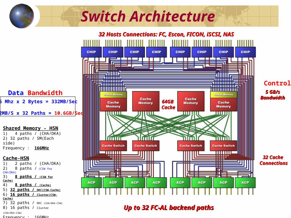
Switch Architecture
64GB 64GB CacheCache
32 Hosts Connections: FC, Escon, FICON, iSCSI, NAS32 Hosts Connections: FC, Escon, FICON, iSCSI, NAS
32 Cache 32 Cache ConnectionsConnections
5 GB/sBandwidth
5 GB/sBandwidth
Shared Memory - HSN1) 4 paths / (CHA/DKA)2) 32 paths / SM(Each side)Frequency : 166MHz
Cache-HSN1) 2 paths / (CHA/DKA)2) 8 paths / (CSW for CHA/DKA)
3) 8 paths / (CSW for Cache)
4) 8 paths / (Cache)
5) 32 paths / DKC(CSW-Cache)
6) 16 paths / Cluster(CSW-Cache)
7) 32 paths / DKC (CHA/DKA-CSW)
8) 16 paths / Cluster (CHA/DKA-CSW) Frequency : 166MHz
Up to 32 FC-AL backend pathsUp to 32 FC-AL backend paths
166 Mhz x 2 Bytes = 332MB/Sec
332MB/S x 32 Paths = 10.6GB/Sec
Data Bandwidth
Control
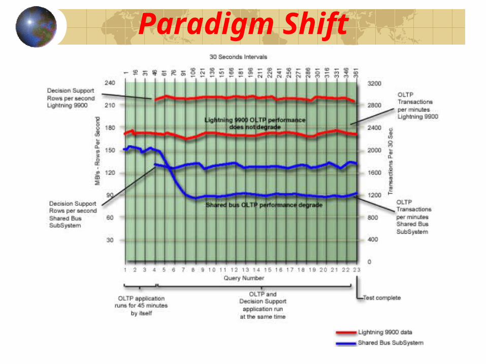
Paradigm Shift
Tangible Benefits
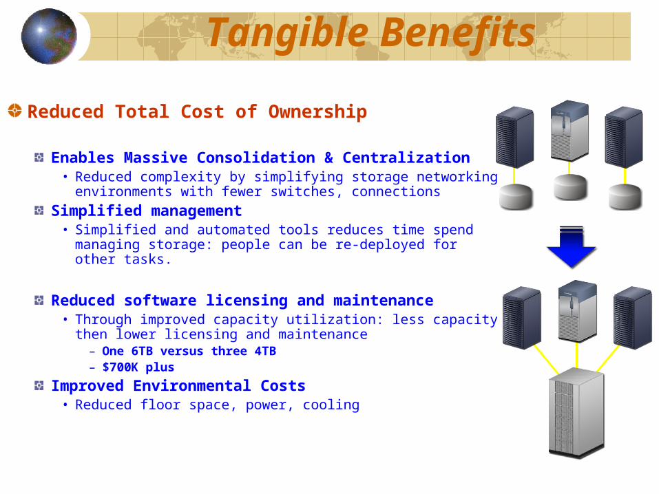
Reduced Total Cost of Ownership
Enables Massive Consolidation & Centralization• Reduced complexity by simplifying storage networking
environments with fewer switches, connectionsSimplified management
• Simplified and automated tools reduces time spend managing storage: people can be re-deployed for other tasks.
Reduced software licensing and maintenance• Through improved capacity utilization: less capacity then
lower licensing and maintenance– One 6TB versus three 4TB– $700K plus
Improved Environmental Costs• Reduced floor space, power, cooling
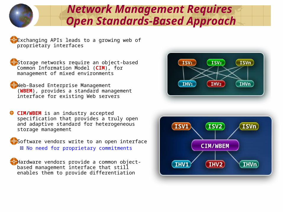
Network Management Requires Open Standards-Based Approach
Exchanging APIs leads to a growing web of proprietary interfaces
Storage networks require an object-based Common Information Model (CIM), for management of mixed environments
Web-Based Enterprise Management(WBEM), provides a standard managementinterface for existing Web servers
CIM/WBEM is an industry accepted specification that provides a truly open and adaptive standard for heterogeneous storage management Software vendors write to an open interface
No need for proprietary commitments
Hardware vendors provide a common object- based management interface that still enables them to provide differentiation
IHV1
ISV1 ISV2 ISVn
IHV2 IHVn
CIM
ISV1 ISV2 ISVn
IHV1 IHV2 IHVn
CIM/WBEM
ISV1 ISV2 ISVn
IHV1 IHV2 IHVn
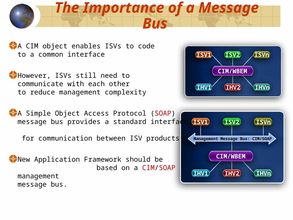
The Importance of a Message Bus
A CIM object enables ISVs to codeto a common interface
However, ISVs still need to communicate with each otherto reduce management complexity
A Simple Object Access Protocol (SOAP) message bus provides a standard interface for communication between ISV products
New Application Framework should be based on a CIM/SOAP management message bus.
CIM/WBEM
ISV1 ISV2 ISVn
IHV1 IHV2 IHVn
CIM/WBEM
ISV1 ISV2 ISVn
IHV1 IHV2 IHVn
Management Message Bus: CIM/SOAP

High Performance, Open Computing
Computer Measurements Group
Thank You
Yves Coderre