Embed Size (px)
Citation preview

SolidWorks
Electrical
2013
Hands-On
Test Drive

Table of Contents
WHAT IS SOLIDWORKS ELECTRICAL? ....................................................................................................... 1
UNDERSTANDING THE WORKFLOW .......................................................................................................... 1
STARTING SOLIDWORKS ELECTRICAL .................................................................................................... 3
THE USER INTERFACE ........................................................................................................................ 3
CREATING AND OPENING PROJECTS ..................................................................................................... 4
CREATING A NEW PROJECT ................................................................................................................ 4
PROJECT OVERVIEW .......................................................................................................................... 4
SINGLE LINE DIAGRAMS ......................................................................................................................... 5
ZOOMING AND SCROLLING ................................................................................................................. 5
MOUSE ZOOM ............................................................................................................................. 5
MOUSE SCROLL ............................................................................................................................ 5
WHERE TO FIND IT ....................................................................................................................... 6
INSERTING SYMBOLS ......................................................................................................................... 6
ADDING CABLES ............................................................................................................................... 8
SOLIDWORKS ELECTRICAL 3D ............................................................................................................... 10
INSERT 3D COMPONENTS ................................................................................................................ 11
ROUTE CABLES IN 3D ...................................................................................................................... 12
POWER AND CONTROL CIRCUITS ........................................................................................................... 13
DRAWING WIRES ............................................................................................................................ 13
OPTIONAL – CUSTOMIZING THE USER INTERFACE ................................................................................. 14
KEYBOARD SHORTCUTS ............................................................................................................... 14
GRAPHICS OPTIONS .................................................................................................................... 15
ADDING SYMBOLS FROM THE PALETTE ............................................................................................... 15
ADDING SYMBOLS FROM EXISTING COMPONENTS ................................................................................ 19
TERMINALS AND TERMINAL STRIPS .................................................................................................... 19
CONTROL DIAGRAMS ...................................................................................................................... 21
OPTIONAL – MACROS ..................................................................................................................... 24
WIRE ORIGIN – DESTINATION ARROWS .............................................................................................. 25
WIRE NUMBERS ............................................................................................................................. 27
OPTIONAL - CREATE A MANUFACTURER PART ..................................................................................... 28
SOLIDWORKS PANEL LAYOUT ............................................................................................................... 28
ROUTE WIRES ................................................................................................................................ 31
REPORTS ........................................................................................................................................... 32
REORGANIZING THE PROJECT ............................................................................................................ 34
OPTIONAL – PUBLISH TO ENTERPRISE PDM ............................................................................................ 34

Pg. 1
SolidWorks Electrical
Hands-On Test Drive
What is SolidWorks Electrical?
SolidWorks Electrical provides a project-based approach to developing electrical designs. All
documentation for an electrical design is contained in the project including single line diagrams, power,
control and PLC schematics, tables and reports, terminal strip drawings and 3D SolidWorks models along
with any additional documentation you wish to attach.
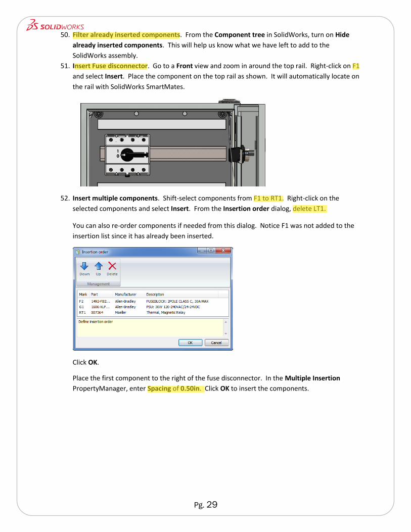
Projects are controlled and stored in a SQL database to allow fast and flexible project access. Multiple
users can work on a single project. While an electrical designer is working out the schematic, another
user can be inserting components in SolidWorks assemblies and routing wires. Projects are updated
real-time with changes for every user to ensure design accuracy.
Components in an electrical design are managed by SolidWorks Electrical so that every symbol and 3D
part is interconnected. The manufacture part reference is associated with each symbol. For example, a
power contactor is represented by several symbols representing the coil and each contact along with a
3D SolidWorks part that will be placed in a cabinet. Every one of these representations of the same
physical part is connected to manufacturer’s part data. If you choose to change the manufacturer’s
part, you change it once and all symbols and representations are updated.
Wires and cables also have built-in intelligence. Wire numbering in SolidWorks Electrical is incredibly
flexible to accommodate a variety of standards and styles. Cables reference a manufacturer’s part just
as any other component with the addition of cores and diameters. When routed in SolidWorks Electrical
3D, they are represented completely and lengths are automatically calculated.
Cross-referencing is automatic in projects. The various symbols for physical components are linked by
mark, by hyperlink and by schematic location so you are sure to never have overused components or
miss-wiring.
SolidWorks Electrical also provides critical design automation for PLCs, reports and terminal strips along
with 3D wire, cable and harness routing so that your project documentation is complete without
additional manual drafting required.
Understanding the Workflow
Single line diagrams provide an excellent project overview along with a quick means to creating basic
cable connections. Symbols are first placed that represent each major electrical component. These
components can be associated to a manufacturer’s part at any time. Cables are then drawn to visually
connect components and optionally connect circuits.
Pg. 2
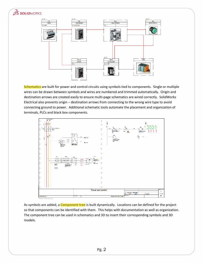
Schematics are built for power and control circuits using symbols tied to components. Single or multiple
wires can be drawn between symbols and wires are numbered and trimmed automatically. Origin and
destination arrows are created easily to ensure multi-page schematics are wired correctly. SolidWorks
Electrical also prevents origin – destination arrows from connecting to the wrong wire type to avoid
connecting ground to power. Additional schematic tools automate the placement and organization of
terminals, PLCs and black box components.
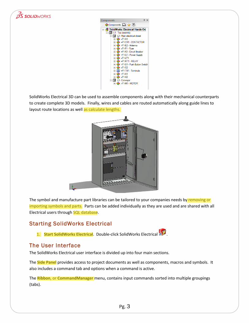
As symbols are added, a Component tree is built dynamically. Locations can be defined for the project
so that components can be identified with them. This helps with documentation as well as organization.
The component tree can be used in schematics and 3D to insert their corresponding symbols and 3D
models.
Pg. 3
SolidWorks Electrical 3D can be used to assemble components along with their mechanical counterparts
to create complete 3D models. Finally, wires and cables are routed automatically along guide lines to
layout route locations as well as calculate lengths.
The symbol and manufacture part libraries can be tailored to your companies needs by removing or
importing symbols and parts. Parts can be added individually as they are used and are shared with all
Electrical users through SQL database.
Starting SolidWorks Electrical
1. Start SolidWorks Electrical. Double-click SolidWorks Electrical .
The User Interface
The SolidWorks Electrical user interface is divided up into four main sections.
The Side Panel provides access to project documents as well as components, macros and symbols. It
also includes a command tab and options when a command is active.
The Ribbon, or CommandManager menu, contains input commands sorted into multiple groupings
(tabs).

Pg. 4
The Graphics Zone is limited to drawing access and editing.
The Status Bar shows the cursor position and allows you to toggle modes like SNAP on and off.
Creating and Opening Projects
A Project is used to store the many different types of files used to create the reports, data and other
files that together fully define the project.
A project contains one or more document books. Each document book can contain many files of
different types including multiple drawings.
Creating a New Project
Creating a new project automatically creates multiple files of several different types. Additional
drawings and other files can be added manually. The structure of a new project is based on a template.
You only need to create an initial project structure and configure its settings once. It can then be saved
as a template to keep all projects consistent and to speed up initial design.
Project Overview
Your goal for this test drive is to complete the electrical documentation and 3D assembly of a three
phase motor control panel that includes a wireless control system.
Ribbon or CommandManager
Side Panel Graphics Zone
Status Bar
Pg. 5
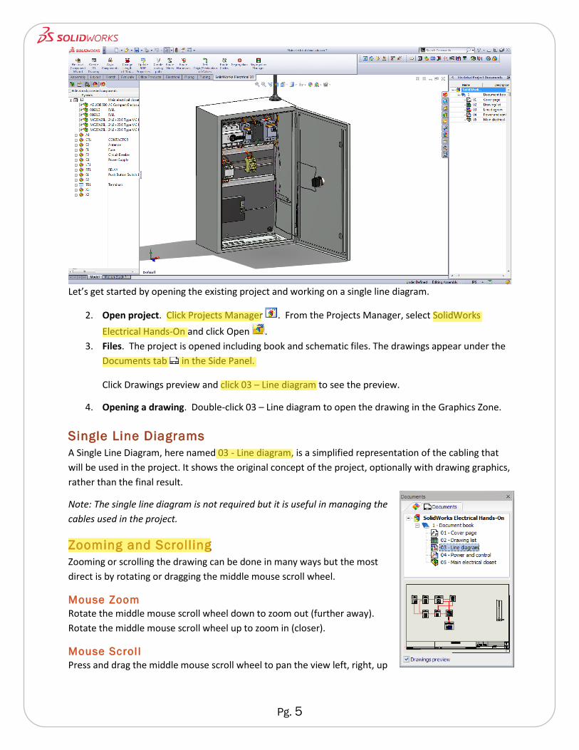
Let’s get started by opening the existing project and working on a single line diagram.
2. Open project. Click Projects Manager . From the Projects Manager, select SolidWorks
Electrical Hands-On and click Open .
3. Files. The project is opened including book and schematic files. The drawings appear under the
Documents tab in the Side Panel.
Click Drawings preview and click 03 – Line diagram to see the preview.
4. Opening a drawing. Double-click 03 – Line diagram to open the drawing in the Graphics Zone.
Single Line Diagrams
A Single Line Diagram, here named 03 - Line diagram, is a simplified representation of the cabling that
will be used in the project. It shows the original concept of the project, optionally with drawing graphics,
rather than the final result.
Note: The single line diagram is not required but it is useful in managing the
cables used in the project.
Zooming and Scrolling
Zooming or scrolling the drawing can be done in many ways but the most
direct is by rotating or dragging the middle mouse scroll wheel.
Mouse Zoom
Rotate the middle mouse scroll wheel down to zoom out (further away).
Rotate the middle mouse scroll wheel up to zoom in (closer).
Mouse Scrol l
Press and drag the middle mouse scroll wheel to pan the view left, right, up

Pg. 6
or down.
Where to Find It
Mouse Button: Rotate or drag with the middle mouse scroll wheel.
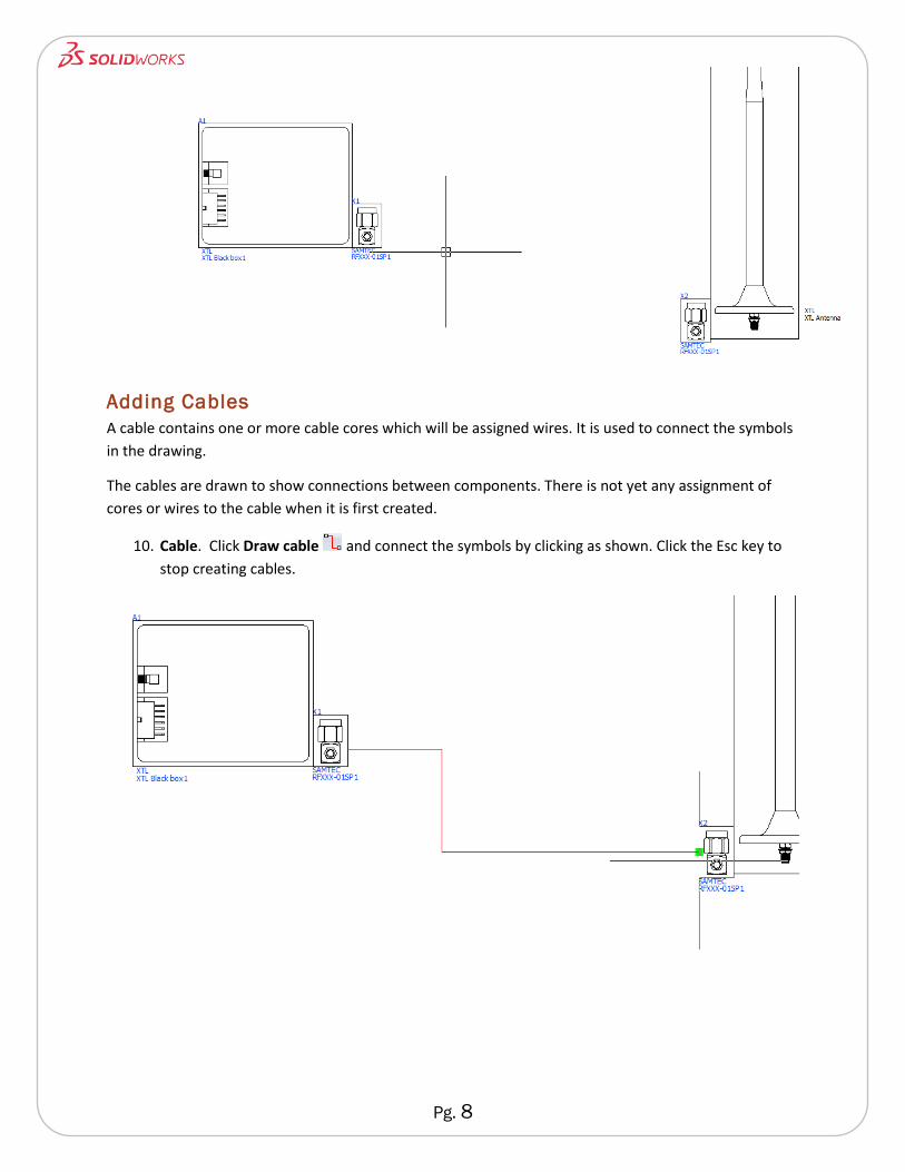
Inserting Symbols
We need to represent the black box and RF connectors on the line diagram and connect them with a
cable. Connectors will be used in this example since they are part of the cable assembly. If the
connectors were part of the component being connected, via screw terminals for example, they would
not need to be included.
5. Select symbol. From the Line diagram tab, click Insert Symbol. If the Symbols selector dialog is
not visible, click the Other symbol button. Select Black boxes from the Classification list, click
Black box1 and click Select.
You can now place the Black box1 symbol on the sheet. Place it to the left of the antenna as
shown.
6. Symbol properties. After placing a symbol, the Symbol properties dialog will be displayed.
Leave the default location and root mark. Select the Manufacturer part and circuits tab and
click Search. Choose XTL as the Manufacturer and click Search. Double-click XTL Black box1
and click Select to associate the manufacturer part data to the symbol. Click OK.
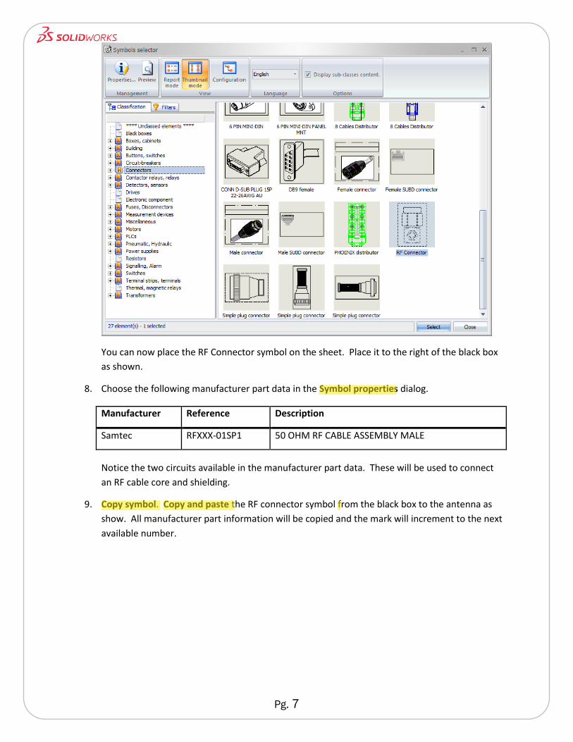
7. Select symbol. From the Line diagram tab, click Insert Symbol. Click the Other symbol button.
Select Connectors from the Classification list and double-click RF Connector.
Pg. 7
You can now place the RF Connector symbol on the sheet. Place it to the right of the black box
as shown.
8. Choose the following manufacturer part data in the Symbol properties dialog.
Manufacturer Reference Description
Samtec RFXXX-01SP1 50 OHM RF CABLE ASSEMBLY MALE
Notice the two circuits available in the manufacturer part data. These will be used to connect
an RF cable core and shielding.
9. Copy symbol. Copy and paste the RF connector symbol from the black box to the antenna as
show. All manufacturer part information will be copied and the mark will increment to the next
available number.
Pg. 8
Adding Cables
A cable contains one or more cable cores which will be assigned wires. It is used to connect the symbols
in the drawing.
The cables are drawn to show connections between components. There is not yet any assignment of
cores or wires to the cable when it is first created.
10. Cable. Click Draw cable and connect the symbols by clicking as shown. Click the Esc key to
stop creating cables.
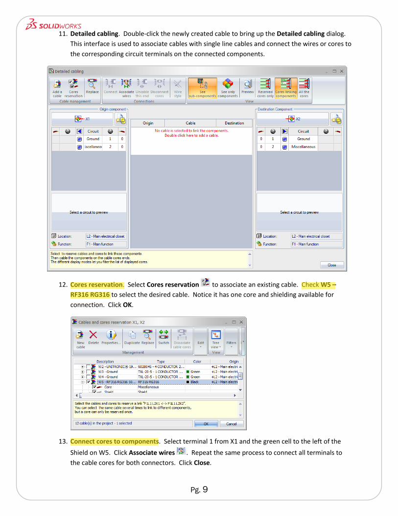
Pg. 9
11. Detailed cabling. Double-click the newly created cable to bring up the Detailed cabling dialog.
This interface is used to associate cables with single line cables and connect the wires or cores to
the corresponding circuit terminals on the connected components.
12. Cores reservation. Select Cores reservation to associate an existing cable. Check W5 –
RF316 RG316 to select the desired cable. Notice it has one core and shielding available for
connection. Click OK.
13. Connect cores to components. Select terminal 1 from X1 and the green cell to the left of the
Shield on W5. Click Associate wires . Repeat the same process to connect all terminals to
the cable cores for both connectors. Click Close.
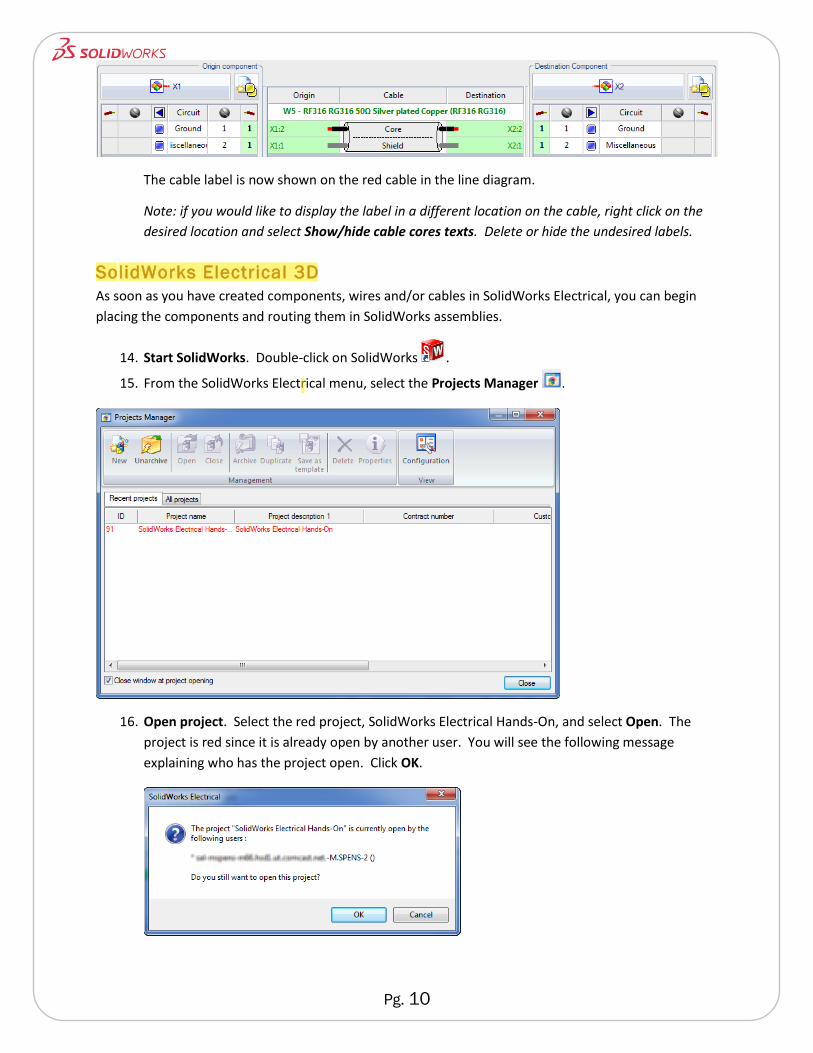
Pg. 10
The cable label is now shown on the red cable in the line diagram.
Note: if you would like to display the label in a different location on the cable, right click on the
desired location and select Show/hide cable cores texts. Delete or hide the undesired labels.
SolidWorks Electrical 3D
As soon as you have created components, wires and/or cables in SolidWorks Electrical, you can begin
placing the components and routing them in SolidWorks assemblies.
14. Start SolidWorks. Double-click on SolidWorks .
15. From the SolidWorks Electrical menu, select the Projects Manager .
16. Open project. Select the red project, SolidWorks Electrical Hands-On, and select Open. The
project is red since it is already open by another user. You will see the following message
explaining who has the project open. Click OK.
Pg. 11
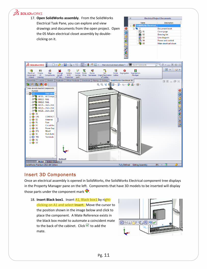
17. Open SolidWorks assembly. From the SolidWorks
Electrical Task Pane, you can explore and view
drawings and documents from the open project. Open
the 05 Main electrical closet assembly by double-
clicking on it.
Insert 3D Components
Once an electrical assembly is opened in SolidWorks, the SolidWorks Electrical component tree displays
in the Property Manager pane on the left. Components that have 3D models to be inserted will display
those parts under the component mark .
18. Insert Black box1. Insert A1, Black box1 by right-
clicking on A1 and select Insert. Move the cursor to
the position shown in the image below and click to
place the component. A Mate Reference exists in
the black box model to automate a coincident mate
to the back of the cabinet. Click to add the
mate.
Pg. 12
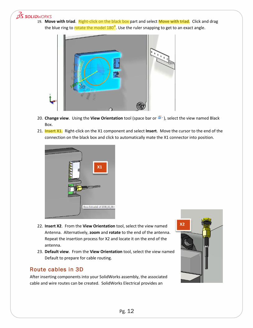
19. Move with triad. Right-click on the black box part and select Move with triad. Click and drag
the blue ring to rotate the model 180°. Use the ruler snapping to get to an exact angle.
20. Change view. Using the View Orientation tool (space bar or ), select the view named Black
Box.
21. Insert X1. Right-click on the X1 component and select Insert. Move the cursor to the end of the
connection on the black box and click to automatically mate the X1 connector into position.
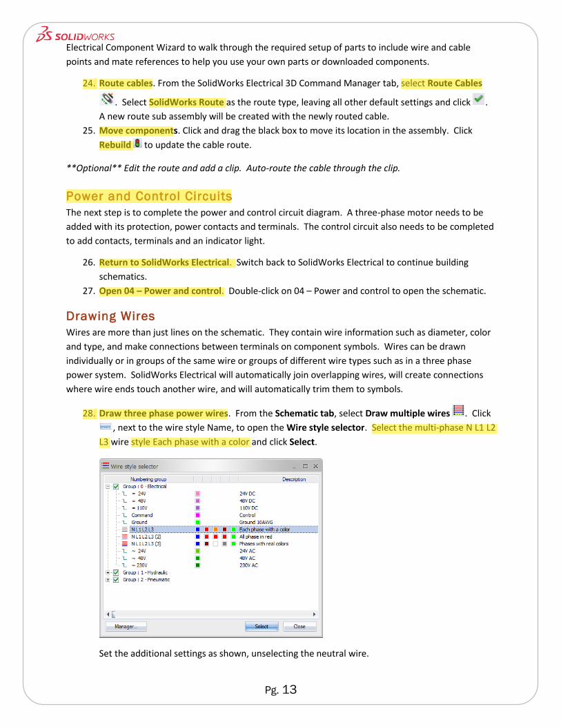
22. Insert X2. From the View Orientation tool, select the view named
Antenna. Alternatively, zoom and rotate to the end of the antenna.
Repeat the insertion process for X2 and locate it on the end of the
antenna.
23. Default view. From the View Orientation tool, select the view named
Default to prepare for cable routing.
Route cables in 3D
After inserting components into your SolidWorks assembly, the associated
cable and wire routes can be created. SolidWorks Electrical provides an
X1
X2
Pg. 13
Electrical Component Wizard to walk through the required setup of parts to include wire and cable
points and mate references to help you use your own parts or downloaded components.
24. Route cables. From the SolidWorks Electrical 3D Command Manager tab, select Route Cables
. Select SolidWorks Route as the route type, leaving all other default settings and click .
A new route sub assembly will be created with the newly routed cable.
25. Move components. Click and drag the black box to move its location in the assembly. Click
Rebuild to update the cable route.
**Optional** Edit the route and add a clip. Auto-route the cable through the clip.
Power and Control Circuits
The next step is to complete the power and control circuit diagram. A three-phase motor needs to be
added with its protection, power contacts and terminals. The control circuit also needs to be completed
to add contacts, terminals and an indicator light.
26. Return to SolidWorks Electrical. Switch back to SolidWorks Electrical to continue building
schematics.
27. Open 04 – Power and control. Double-click on 04 – Power and control to open the schematic.
Drawing Wires
Wires are more than just lines on the schematic. They contain wire information such as diameter, color
and type, and make connections between terminals on component symbols. Wires can be drawn
individually or in groups of the same wire or groups of different wire types such as in a three phase
power system. SolidWorks Electrical will automatically join overlapping wires, will create connections
where wire ends touch another wire, and will automatically trim them to symbols.
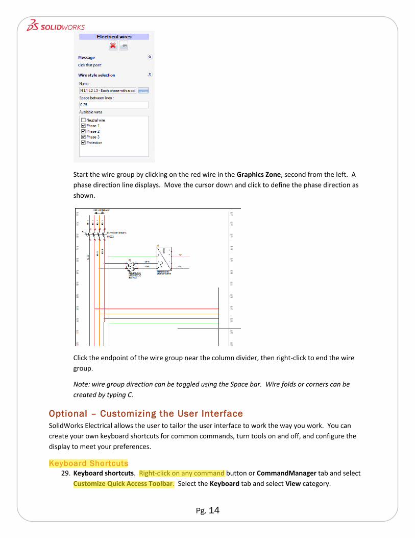
28. Draw three phase power wires. From the Schematic tab, select Draw multiple wires . Click
, next to the wire style Name, to open the Wire style selector. Select the multi-phase N L1 L2
L3 wire style Each phase with a color and click Select.
Set the additional settings as shown, unselecting the neutral wire.
Pg. 14
Start the wire group by clicking on the red wire in the Graphics Zone, second from the left. A
phase direction line displays. Move the cursor down and click to define the phase direction as
shown.
Click the endpoint of the wire group near the column divider, then right-click to end the wire
group.
Note: wire group direction can be toggled using the Space bar. Wire folds or corners can be
created by typing C.
Optional – Customizing the User Interface
SolidWorks Electrical allows the user to tailor the user interface to work the way you work. You can
create your own keyboard shortcuts for common commands, turn tools on and off, and configure the
display to meet your preferences.
Keyboard Shortcuts
29. Keyboard shortcuts. Right-click on any command button or CommandManager tab and select
Customize Quick Access Toolbar. Select the Keyboard tab and select View category.
Pg. 15
Type F into the Press new shortcut key box and click Assign. Typing F on the keyboard will now
zoom the sheet to fit the screen.
Note: keyboard shortcuts are specific to the document type.
Graphics Options
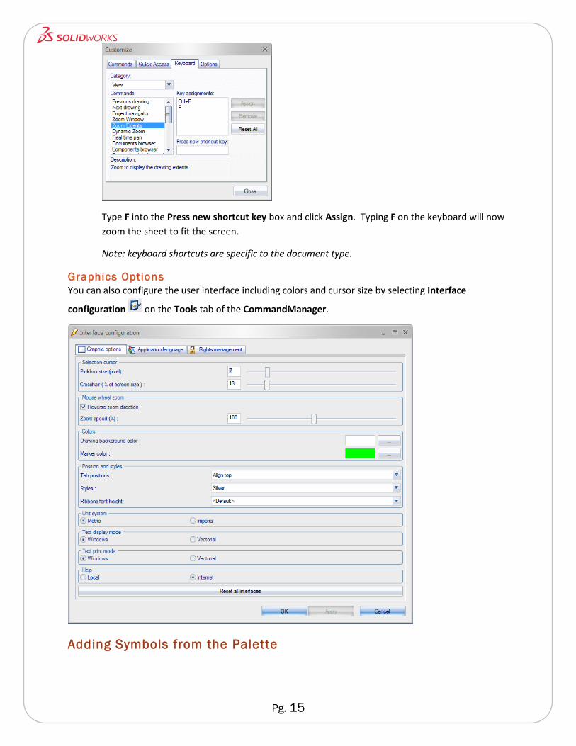
You can also configure the user interface including colors and cursor size by selecting Interface
configuration on the Tools tab of the CommandManager.
Adding Symbols from the Palette
Pg. 16
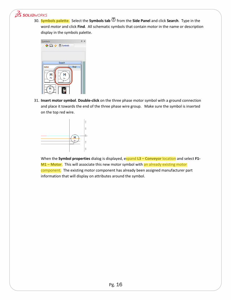
30. Symbols palette. Select the Symbols tab from the Side Panel and click Search. Type in the
word motor and click Find. All schematic symbols that contain motor in the name or description
display in the symbols palette.
31. Insert motor symbol. Double-click on the three phase motor symbol with a ground connection
and place it towards the end of the three phase wire group. Make sure the symbol is inserted
on the top red wire.
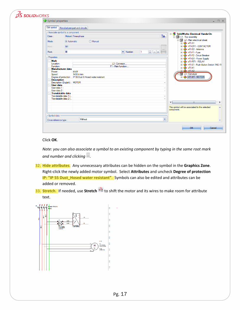
When the Symbol properties dialog is displayed, expand L3 – Conveyor location and select F1-
M1 – Motor. This will associate this new motor symbol with an already existing motor
component. The existing motor component has already been assigned manufacturer part
information that will display on attributes around the symbol.
Pg. 17
Click OK.
Note: you can also associate a symbol to an existing component by typing in the same root mark
and number and clicking .
32. Hide attributes. Any unnecessary attributes can be hidden on the symbol in the Graphics Zone.
Right-click the newly added motor symbol. Select Attributes and uncheck Degree of protection
IP: “IP 55 Dust_Hosed water resistant”. Symbols can also be edited and attributes can be
added or removed.
33. Stretch. If needed, use Stretch to shift the motor and its wires to make room for attribute
text.
Pg. 18
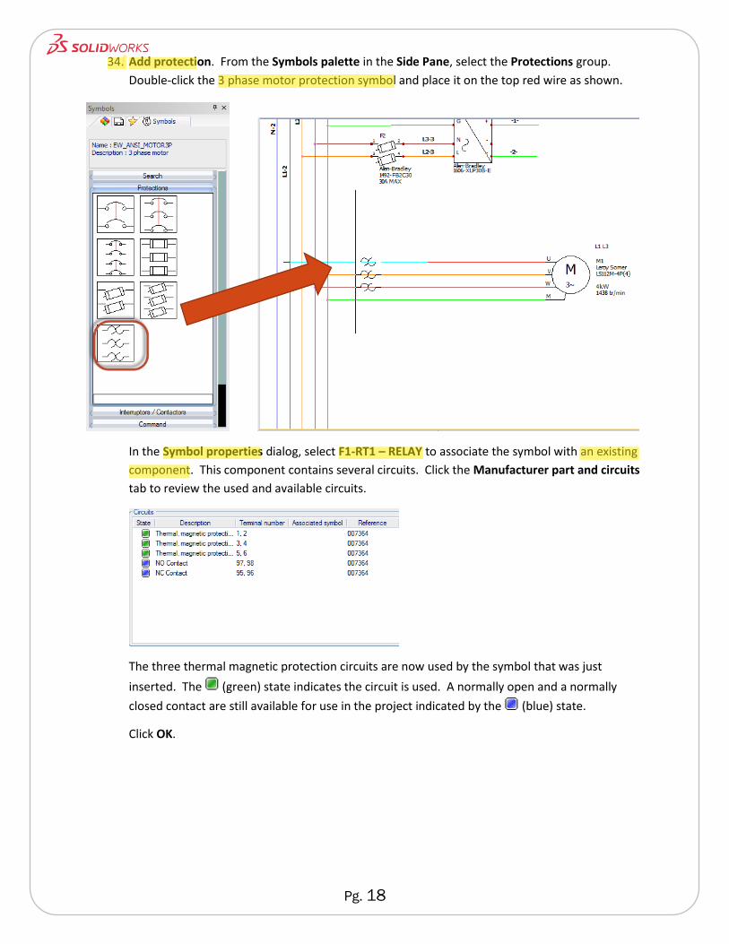
34. Add protection. From the Symbols palette in the Side Pane, select the Protections group.
Double-click the 3 phase motor protection symbol and place it on the top red wire as shown.
In the Symbol properties dialog, select F1-RT1 – RELAY to associate the symbol with an existing
component. This component contains several circuits. Click the Manufacturer part and circuits
tab to review the used and available circuits.
The three thermal magnetic protection circuits are now used by the symbol that was just
inserted. The (green) state indicates the circuit is used. A normally open and a normally
closed contact are still available for use in the project indicated by the (blue) state.
Click OK.
Pg. 19
Note: the cross reference contact symbols added with the relay can be moved or hidden. Click
and drag the cross references to move them. To hide them, go to the Symbol properties of the
newly inserted symbol and set the Cross reference type to Without.
Adding Symbols from Existing Components
You are not limited to dropping in a symbol and then associating it with a manufacturer part or existing
component. You can create components directly in the Components tree or line diagram and then
insert their corresponding symbols from the component itself.
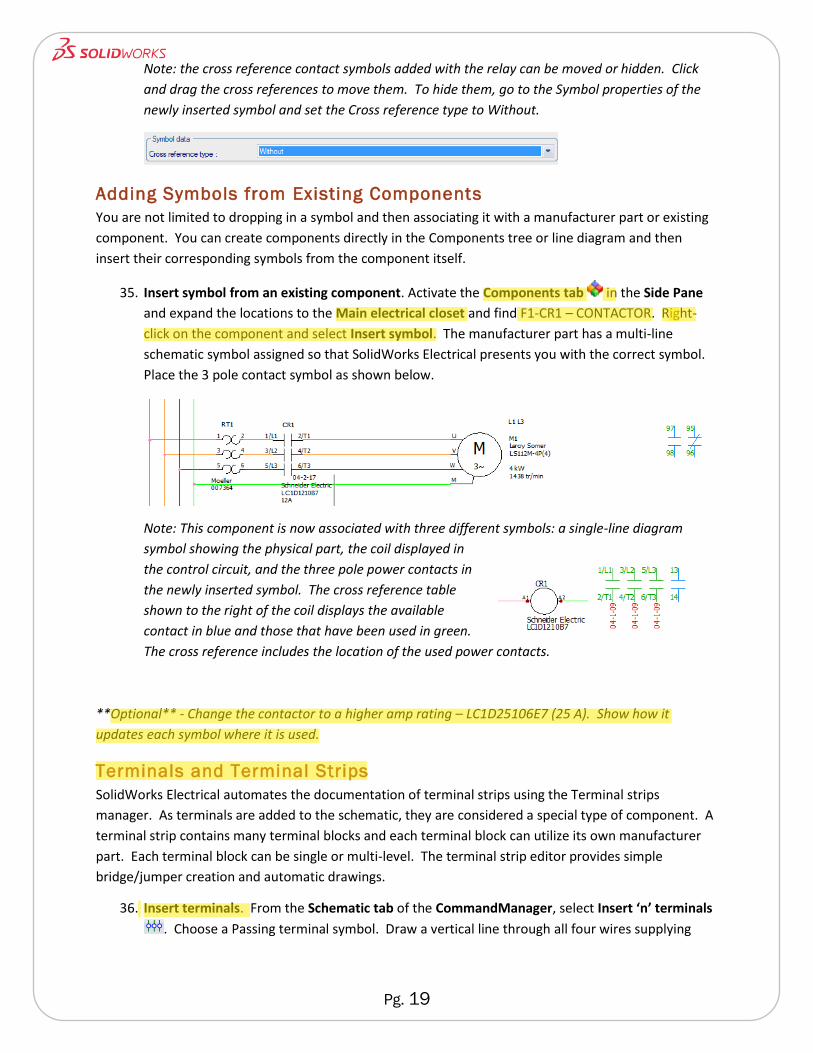
35. Insert symbol from an existing component. Activate the Components tab in the Side Pane
and expand the locations to the Main electrical closet and find F1-CR1 – CONTACTOR. Right-
click on the component and select Insert symbol. The manufacturer part has a multi-line
schematic symbol assigned so that SolidWorks Electrical presents you with the correct symbol.
Place the 3 pole contact symbol as shown below.
Note: This component is now associated with three different symbols: a single-line diagram
symbol showing the physical part, the coil displayed in
the control circuit, and the three pole power contacts in
the newly inserted symbol. The cross reference table
shown to the right of the coil displays the available
contact in blue and those that have been used in green.
The cross reference includes the location of the used power contacts.
**Optional** - Change the contactor to a higher amp rating – LC1D25106E7 (25 A). Show how it
updates each symbol where it is used.
Terminals and Terminal Strips
SolidWorks Electrical automates the documentation of terminal strips using the Terminal strips
manager. As terminals are added to the schematic, they are considered a special type of component. A
terminal strip contains many terminal blocks and each terminal block can utilize its own manufacturer
part. Each terminal block can be single or multi-level. The terminal strip editor provides simple
bridge/jumper creation and automatic drawings.
36. Insert terminals. From the Schematic tab of the CommandManager, select Insert ‘n’ terminals
. Choose a Passing terminal symbol. Draw a vertical line through all four wires supplying
Pg. 20
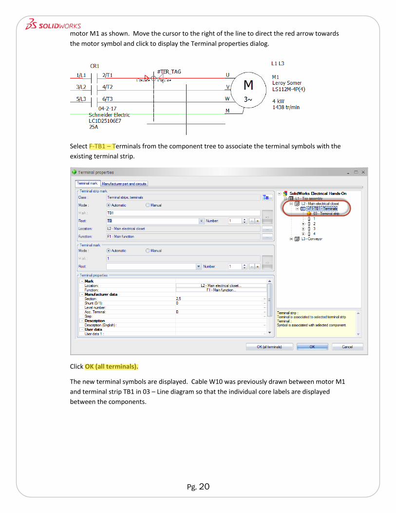
motor M1 as shown. Move the cursor to the right of the line to direct the red arrow towards
the motor symbol and click to display the Terminal properties dialog.
Select F-TB1 – Terminals from the component tree to associate the terminal symbols with the
existing terminal strip.
Click OK (all terminals).
The new terminal symbols are displayed. Cable W10 was previously drawn between motor M1
and terminal strip TB1 in 03 – Line diagram so that the individual core labels are displayed
between the components.
Pg. 21
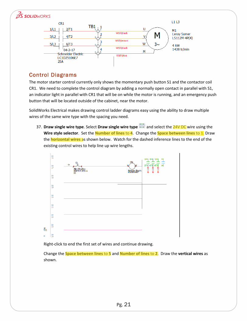
Control Diagrams
The motor starter control currently only shows the momentary push button S1 and the contactor coil
CR1. We need to complete the control diagram by adding a normally open contact in parallel with S1,
an indicator light in parallel with CR1 that will be on while the motor is running, and an emergency push
button that will be located outside of the cabinet, near the motor.
SolidWorks Electrical makes drawing control ladder diagrams easy using the ability to draw multiple
wires of the same wire type with the spacing you need.
37. Draw single wire type. Select Draw single wire type and select the 24V DC wire using the
Wire style selector. Set the Number of lines to 4. Change the Space between lines to 1. Draw
the horizontal wires as shown below. Watch for the dashed inference lines to the end of the
existing control wires to help line up wire lengths.
Right-click to end the first set of wires and continue drawing.
Change the Space between lines to 5 and Number of lines to 2. Draw the vertical wires as
shown.
Pg. 22
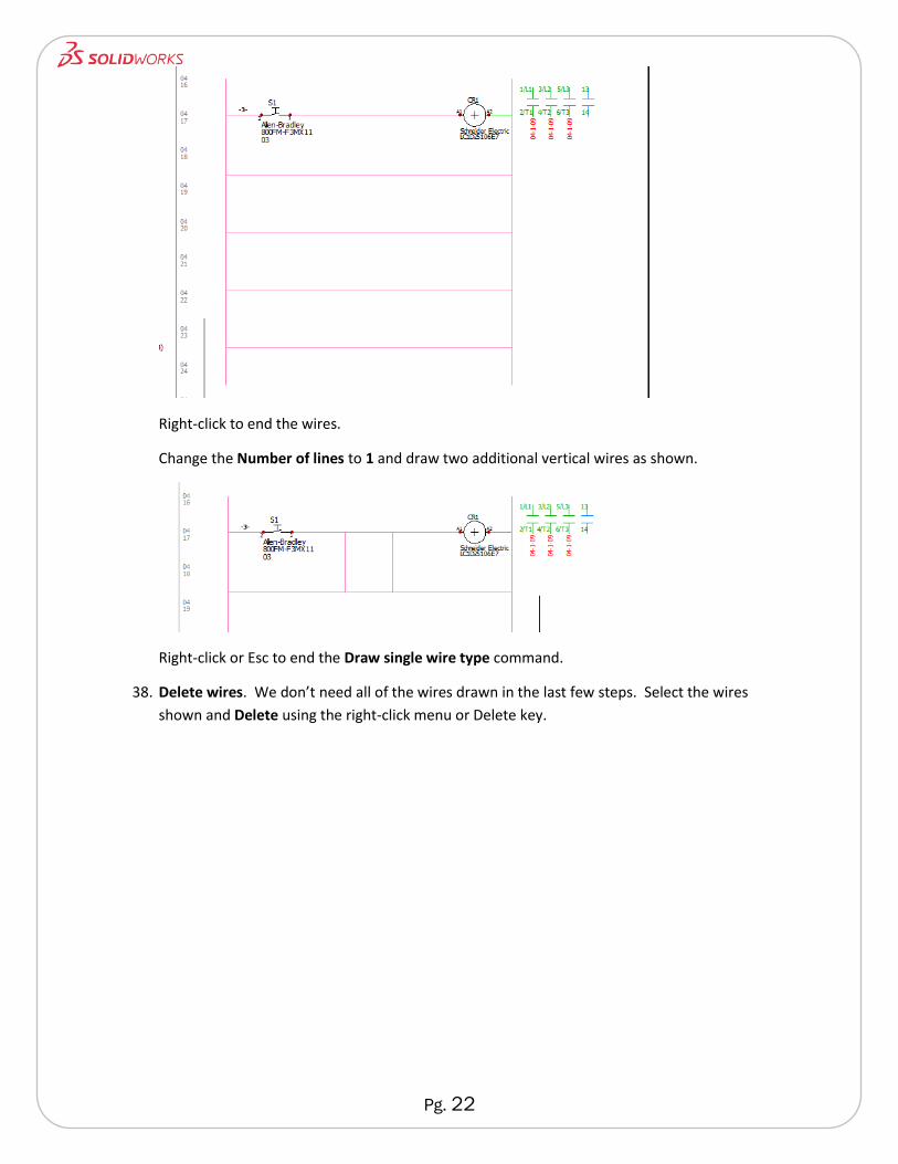
Right-click to end the wires.
Change the Number of lines to 1 and draw two additional vertical wires as shown.
Right-click or Esc to end the Draw single wire type command.
38. Delete wires. We don’t need all of the wires drawn in the last few steps. Select the wires
shown and Delete using the right-click menu or Delete key.
Pg. 23
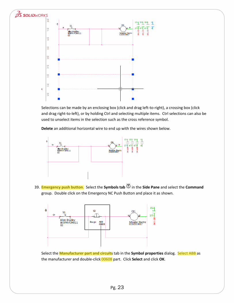
Selections can be made by an enclosing box (click and drag left-to-right), a crossing box (click
and drag right-to-left), or by holding Ctrl and selecting multiple items. Ctrl selections can also be
used to unselect items in the selection such as the cross reference symbol.
Delete an additional horizontal wire to end up with the wires shown below.
39. Emergency push button. Select the Symbols tab in the Side Pane and select the Command
group. Double click on the Emergency NC Push Button and place it as shown.
Select the Manufacturer part and circuits tab in the Symbol properties dialog. Select ABB as
the manufacturer and double-click 00608 part. Click Select and click OK.
Pg. 24
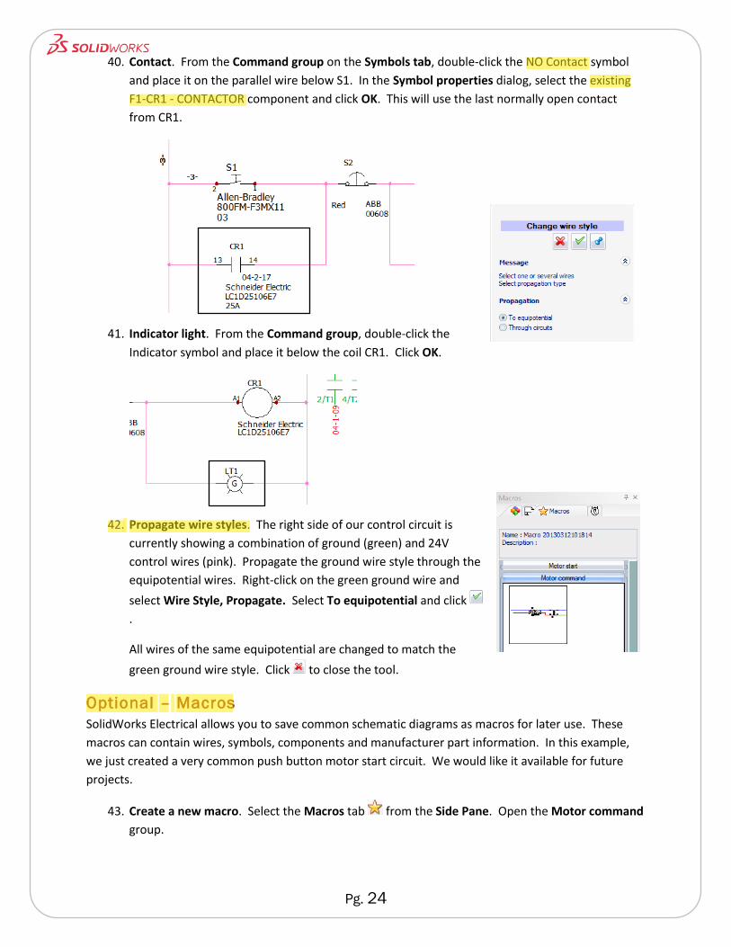
40. Contact. From the Command group on the Symbols tab, double-click the NO Contact symbol
and place it on the parallel wire below S1. In the Symbol properties dialog, select the existing
F1-CR1 - CONTACTOR component and click OK. This will use the last normally open contact
from CR1.
41. Indicator light. From the Command group, double-click the
Indicator symbol and place it below the coil CR1. Click OK.
42. Propagate wire styles. The right side of our control circuit is
currently showing a combination of ground (green) and 24V
control wires (pink). Propagate the ground wire style through the
equipotential wires. Right-click on the green ground wire and
select Wire Style, Propagate. Select To equipotential and click
.
All wires of the same equipotential are changed to match the
green ground wire style. Click to close the tool.
Optional – Macros
SolidWorks Electrical allows you to save common schematic diagrams as macros for later use. These
macros can contain wires, symbols, components and manufacturer part information. In this example,
we just created a very common push button motor start circuit. We would like it available for future
projects.
43. Create a new macro. Select the Macros tab from the Side Pane. Open the Motor command
group.

Pg. 25
Window select the entire motor command circuit with its symbols and wires. Click and drag the
selected contents into the Motor command group. The Macro dialog will appear.
Name the macro Common Motor Command Macro. Click OK.
The new macro can now be dragged and dropped into any project. Manufacturer part
information is already populated and mark numbers will automatically increment if the mark is
already present.
44. Insert macro. Drag and drop the newly created macro just below the existing motor command
diagram. Notice the incrementing of marks the inclusion of manufacturer part information.
There is a new cross reference table added for the new contactor coil. Since its power contacts
are not yet used, they are displayed blue in the table.
Wire Origin – Destination Arrows
SolidWorks Electrical makes it easy to manage wires between schematic diagrams and even from sheet
to sheet. Origin - destination arrows can be created between wires of the same type and provide
hyperlinking between locations.
45. Manage origin – destination arrows. Select Manage origin – destination arrows from the
Schematic tab on the CommandManager.
You can arrange multiple sheets vertically or horizontally as needed. Click Vertical tiles .
Click Single insertion and move your cursor near the end of the pink control wire leaving the
power supply. The green circle indicates a valid starting point for the origin arrow. Click to
place the origin symbol.
Pg. 26
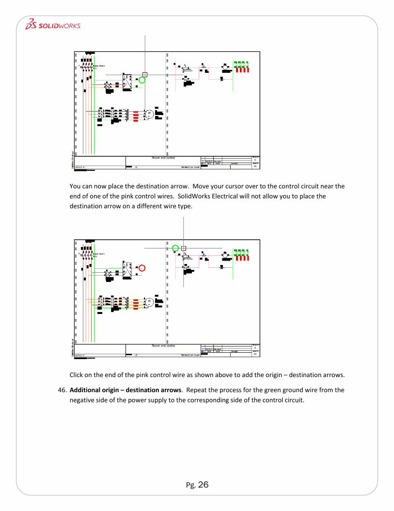
You can now place the destination arrow. Move your cursor over to the control circuit near the
end of one of the pink control wires. SolidWorks Electrical will not allow you to place the
destination arrow on a different wire type.
Click on the end of the pink control wire as shown above to add the origin – destination arrows.
46. Additional origin – destination arrows. Repeat the process for the green ground wire from the
negative side of the power supply to the corresponding side of the control circuit.
Pg. 27
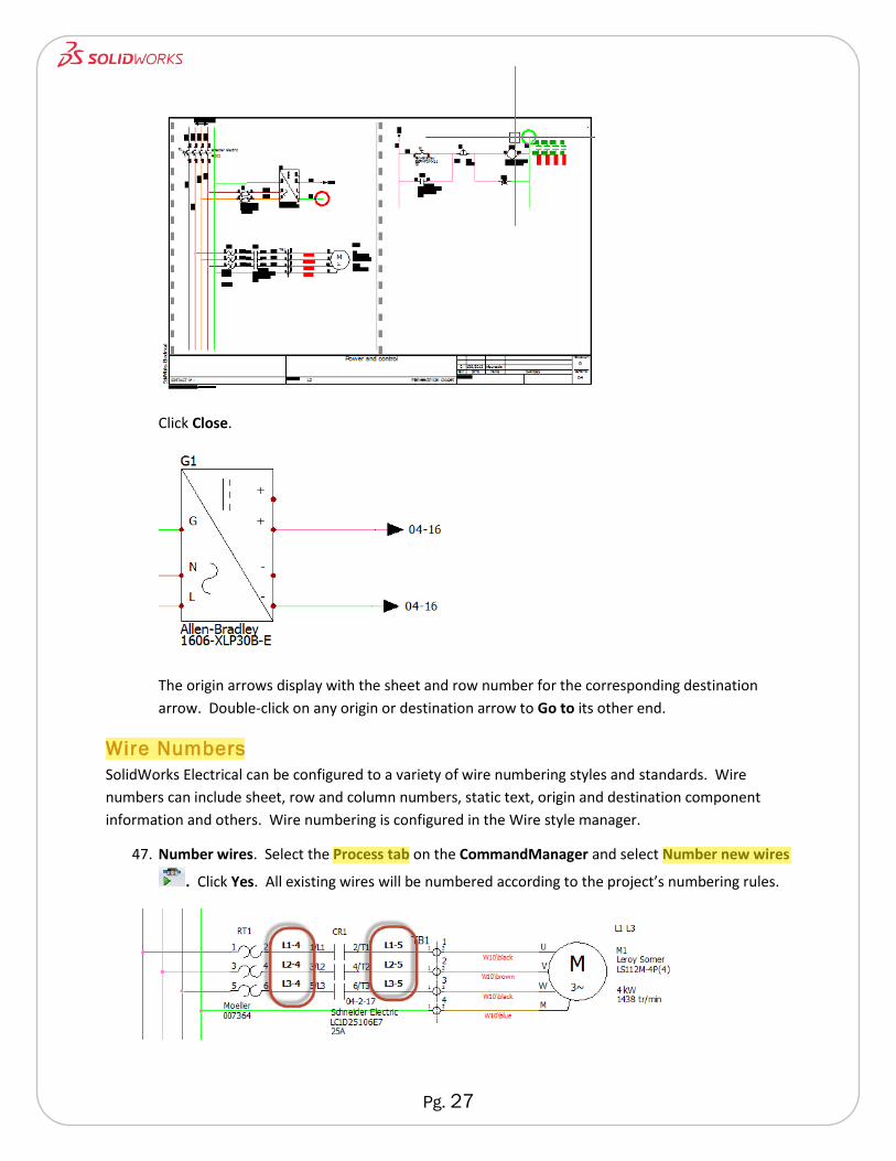
Click Close.
The origin arrows display with the sheet and row number for the corresponding destination
arrow. Double-click on any origin or destination arrow to Go to its other end.
Wire Numbers
SolidWorks Electrical can be configured to a variety of wire numbering styles and standards. Wire
numbers can include sheet, row and column numbers, static text, origin and destination component
information and others. Wire numbering is configured in the Wire style manager.
47. Number wires. Select the Process tab on the CommandManager and select Number new wires
. Click Yes. All existing wires will be numbered according to the project’s numbering rules.
Pg. 28
You can hide and show wire numbers on any wire line by right-clicking and toggling Show/hide wire
marks.
Optional - Create a Manufacturer Part
The SolidWorks Electrical library comes with nearly 500,000 manufacturer parts. That may seem like a
lot, but it is only a small fraction of what can actually be purchased. You may need to add to the library
for parts you use. They can be added individually or in bulk from a spreadsheet.
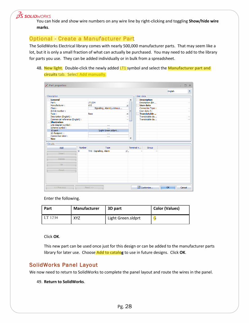
48. New light. Double-click the newly added LT1 symbol and select the Manufacturer part and
circuits tab. Select Add manually.
Enter the following.
Part Manufacturer 3D part Color (Values)
LT 1234 XYZ Light Green.sldprt G
Click OK.
This new part can be used once just for this design or can be added to the manufacturer parts
library for later use. Choose Add to catalog to use in future designs. Click OK.
SolidWorks Panel Layout
We now need to return to SolidWorks to complete the panel layout and route the wires in the panel.
49. Return to SolidWorks.
Pg. 29
50. Filter already inserted components. From the Component tree in SolidWorks, turn on Hide
already inserted components. This will help us know what we have left to add to the
SolidWorks assembly.
51. Insert Fuse disconnector. Go to a Front view and zoom in around the top rail. Right-click on F1
and select Insert. Place the component on the top rail as shown. It will automatically locate on
the rail with SolidWorks SmartMates.
52. Insert multiple components. Shift-select components from F1 to RT1. Right-click on the
selected components and select Insert. From the Insertion order dialog, delete LT1.
You can also re-order components if needed from this dialog. Notice F1 was not added to the
insertion list since it has already been inserted.
Click OK.
Place the first component to the right of the fuse disconnector. In the Multiple Insertion
PropertyManager, enter Spacing of 0.50in. Click OK to insert the components.
Pg. 30
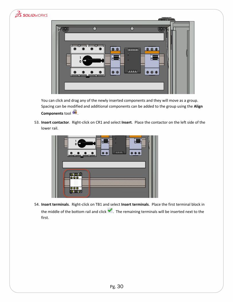
You can click and drag any of the newly inserted components and they will move as a group.
Spacing can be modified and additional components can be added to the group using the Align
Components tool .
53. Insert contactor. Right-click on CR1 and select Insert. Place the contactor on the left side of the
lower rail.
54. Insert terminals. Right-click on TB1 and select Insert terminals. Place the first terminal block in
the middle of the bottom rail and click . The remaining terminals will be inserted next to the
first.
Pg. 31
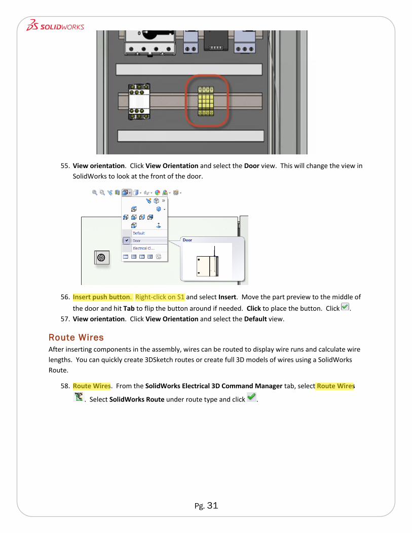
55. View orientation. Click View Orientation and select the Door view. This will change the view in
SolidWorks to look at the front of the door.
56. Insert push button. Right-click on S1 and select Insert. Move the part preview to the middle of
the door and hit Tab to flip the button around if needed. Click to place the button. Click .
57. View orientation. Click View Orientation and select the Default view.
Route Wires
After inserting components in the assembly, wires can be routed to display wire runs and calculate wire
lengths. You can quickly create 3DSketch routes or create full 3D models of wires using a SolidWorks
Route.
58. Route Wires. From the SolidWorks Electrical 3D Command Manager tab, select Route Wires
. Select SolidWorks Route under route type and click .
Pg. 32
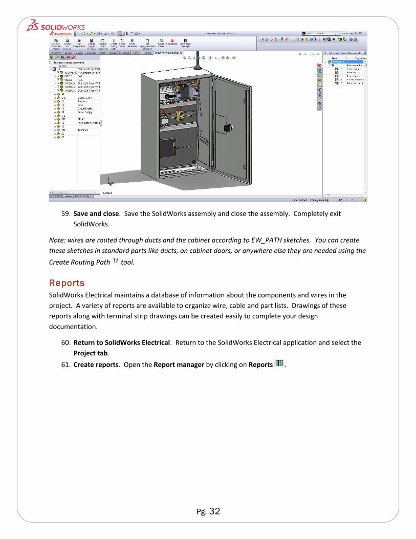
59. Save and close. Save the SolidWorks assembly and close the assembly. Completely exit
SolidWorks.
Note: wires are routed through ducts and the cabinet according to EW_PATH sketches. You can create
these sketches in standard parts like ducts, on cabinet doors, or anywhere else they are needed using the
Create Routing Path tool.
Reports
SolidWorks Electrical maintains a database of information about the components and wires in the
project. A variety of reports are available to organize wire, cable and part lists. Drawings of these
reports along with terminal strip drawings can be created easily to complete your design
documentation.
60. Return to SolidWorks Electrical. Return to the SolidWorks Electrical application and select the
Project tab.
61. Create reports. Open the Report manager by clicking on Reports .
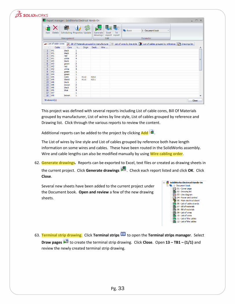
Pg. 33
This project was defined with several reports including List of cable cores, Bill Of Materials
grouped by manufacturer, List of wires by line style, List of cables grouped by reference and
Drawing list. Click through the various reports to review the content.
Additional reports can be added to the project by clicking Add .
The List of wires by line style and List of cables grouped by reference both have length
information on some wires and cables. These have been routed in the SolidWorks assembly.
Wire and cable lengths can also be modified manually by using Wire cabling order.
62. Generate drawings. Reports can be exported to Excel, text files or created as drawing sheets in
the current project. Click Generate drawings . Check each report listed and click OK. Click
Close.
Several new sheets have been added to the current project under
the Document book. Open and review a few of the new drawing
sheets.
63. Terminal strip drawing. Click Terminal strips to open the Terminal strips manager. Select
Draw pages to create the terminal strip drawing. Click Close. Open 13 – TB1 – (1/1) and
review the newly created terminal strip drawing.
Pg. 34
Reorganizing the Project
Reorganizing sheets and cross references is easy using SolidWorks Electrical. Sheets can be re-ordered
by drag and drop. Sheets can be renumbered. All cross references indicating sheet information will be
updated with any reorganization.
64. Move a drawing sheet. From the Documents tab in the Side Pane, drag 13 – TB1 – (1/1) to a
position above 04 – Power and control.
65. Renumber drawing sheets. Right-click on 1 – Document book and select Renumber drawings.
Click OK.
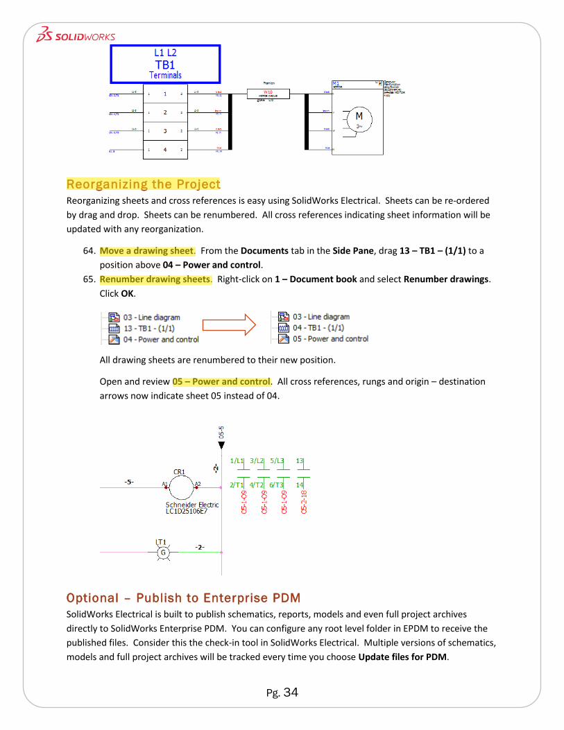
All drawing sheets are renumbered to their new position.
Open and review 05 – Power and control. All cross references, rungs and origin – destination
arrows now indicate sheet 05 instead of 04.
Optional – Publish to Enterprise PDM
SolidWorks Electrical is built to publish schematics, reports, models and even full project archives
directly to SolidWorks Enterprise PDM. You can configure any root level folder in EPDM to receive the
published files. Consider this the check-in tool in SolidWorks Electrical. Multiple versions of schematics,
models and full project archives will be tracked every time you choose Update files for PDM.
Pg. 35
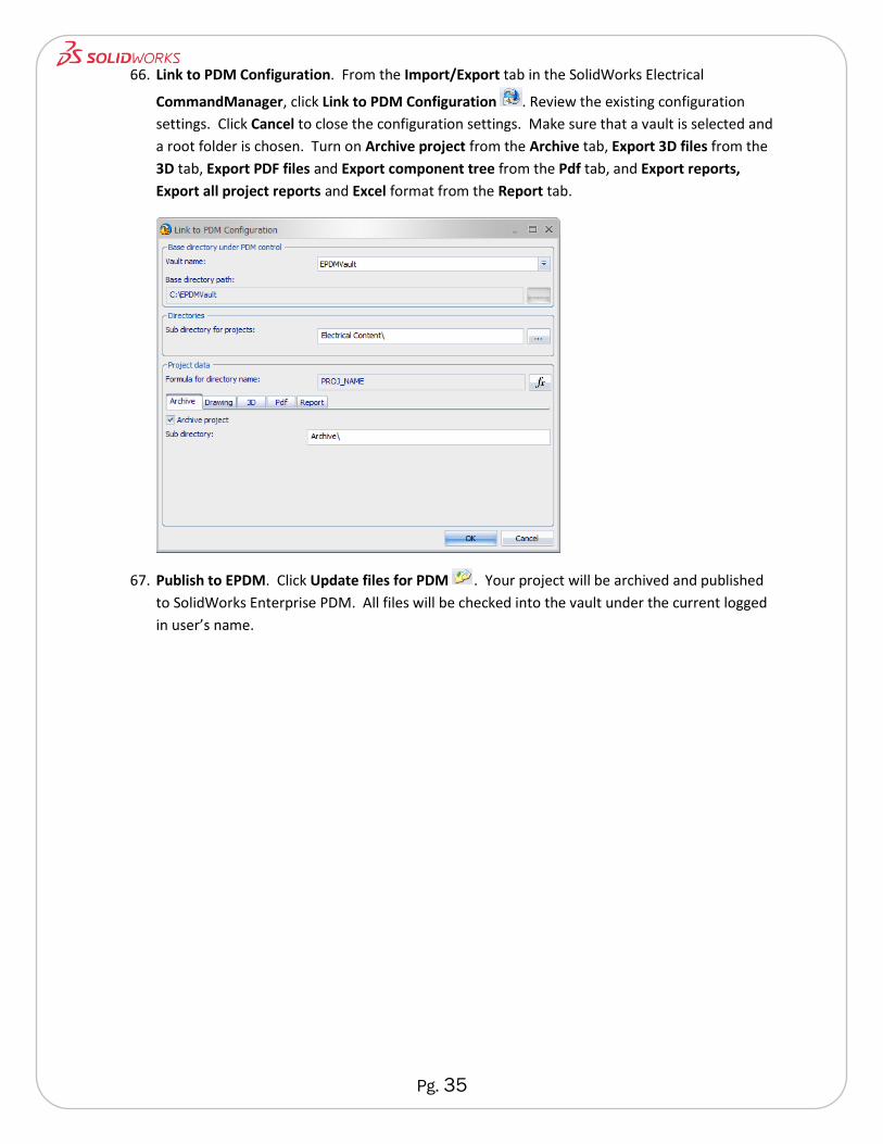
66. Link to PDM Configuration. From the Import/Export tab in the SolidWorks Electrical
CommandManager, click Link to PDM Configuration . Review the existing configuration
settings. Click Cancel to close the configuration settings. Make sure that a vault is selected and
a root folder is chosen. Turn on Archive project from the Archive tab, Export 3D files from the
3D tab, Export PDF files and Export component tree from the Pdf tab, and Export reports,
Export all project reports and Excel format from the Report tab.
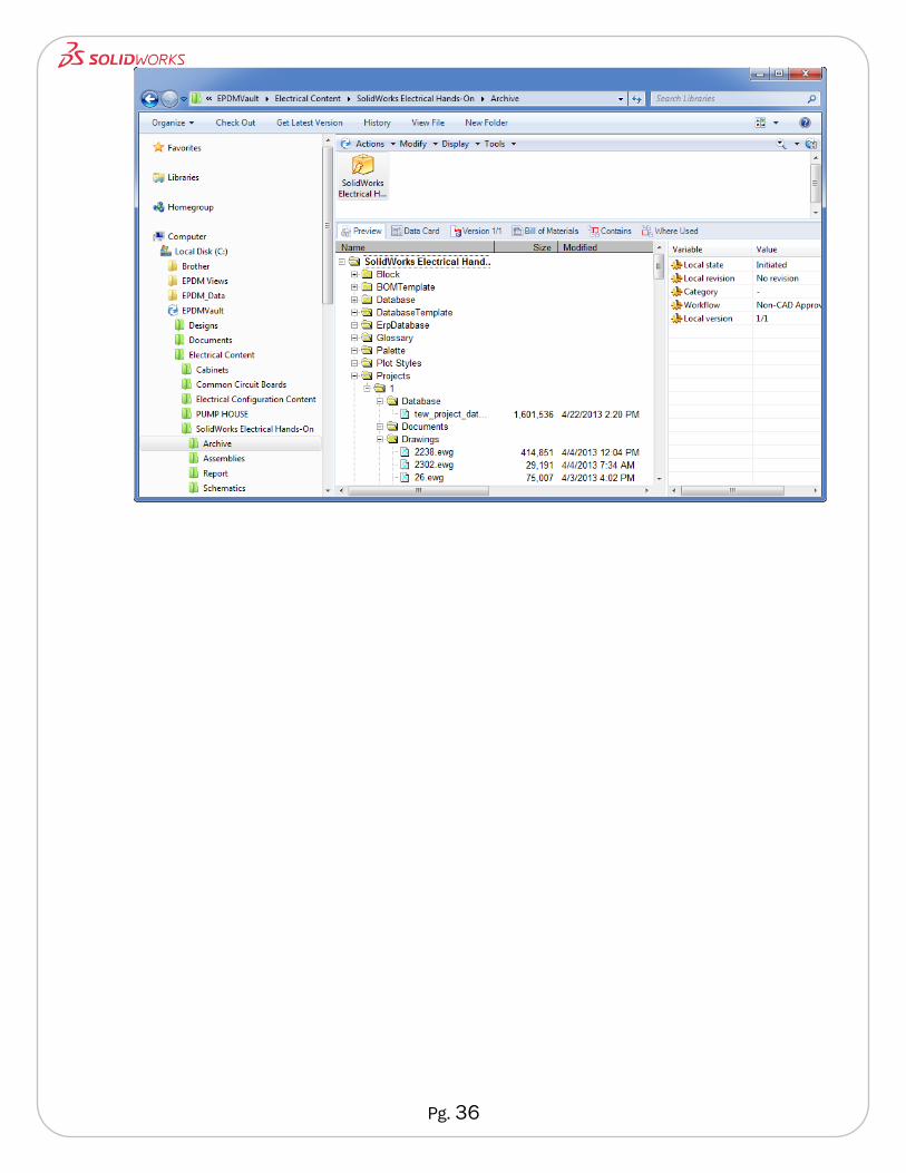
67. Publish to EPDM. Click Update files for PDM . Your project will be archived and published
to SolidWorks Enterprise PDM. All files will be checked into the vault under the current logged
in user’s name.
Pg. 36