Embed Size (px)
Citation preview
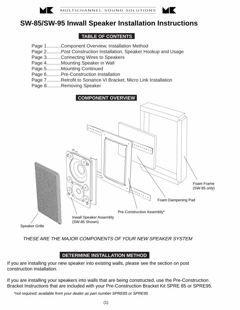
SW-85/SW-95 Inwall Speaker Installation Instructions
COMPONENT OVERVIEW
Speaker Grille
Inwall Speaker Assembly(SW-85 Shown)
Pre-Construction Assembly*
THESE ARE THE MAJOR COMPONENTS OF YOUR NEW SPEAKER SYSTEM
If you are installing your new speaker into existing walls, please see the section on postconstruction installation.
If you are installing your speakers into walls that are being constructed, use the Pre-ConstructionBracket Instructions that are included with your Pre-Construction Bracket Kit SPRE 85 or SPRE95.
DETERMINE INSTALLATION METHOD
*not required; available from your dealer as part number SPRE85 or SPRE95
(1)
Foam Dampening Pad
Foam Frame(SW-95 only)
TABLE OF CONTENTS
Page 1...........Component Overview, Installation MethodPage 2...........Post Construction Installation, Speaker Hookup and UsagePage 3...........Connecting Wires to SpeakersPage 4...........Mounting Speaker in WallPage 5...........Mounting ContinuedPage 6...........Pre-Construction InstallationPage 7...........Retrofit to Sonance VI Bracket, Micro Link InstallationPage 8...........Removing Speaker
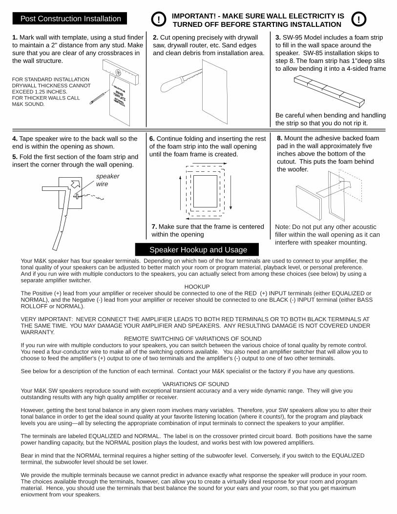
Post Construction Installation ! !IMPORTANT! - MAKE SURE WALL ELECTRICITY ISTURNED OFF BEFORE STARTING INSTALLATION
1. Mark wall with template, using a stud finderto maintain a 2" distance from any stud. Makesure that you are clear of any crossbraces inthe wall structure.
4. Tape speaker wire to the back wall so the end is within the opening as shown.
5. Fold the first section of the foam strip andinsert the corner through the wall opening.
6. Continue folding and inserting the rest of the foam strip into the wall opening until the foam frame is created.
2. Cut opening precisely with drywall saw, drywall router, etc. Sand edges and clean debris from installation area.
3. SW-95 Model includes a foam stripto fill in the wall space around the speaker. SW-85 installation skips tostep 8. The foam strip has 1"deep slits to allow bending it into a 4-sided frame
Be careful when bending and handlingthe strip so that you do not rip it.
8. Mount the adhesive backed foampad in the wall approximately fiveinches above the bottom of thecutout. This puts the foam behindthe woofer.
Speaker Hookup and UsageYour M&K speaker has four speaker terminals. Depending on which two of the four terminals are used to connect to your amplifier, the tonal quality of your speakers can be adjusted to better match your room or program material, playback level, or personal preference. And if you run wire with multiple conductors to the speakers, you can actually select from among these choices (see below) by using a separate amplifier switcher.
HOOKUPThe Positive (+) lead from your amplifier or receiver should be connected to one of the RED (+) INPUT terminals (either EQUALIZED or NORMAL), and the Negative (-) lead from your amplifier or receiver should be connected to one BLACK (-) INPUT terminal (either BASS ROLLOFF or NORMAL).
VERY IMPORTANT: NEVER CONNECT THE AMPLIFIER LEADS TO BOTH RED TERMINALS OR TO BOTH BLACK TERMINALS AT THE SAME TIME. YOU MAY DAMAGE YOUR AMPLIFIER AND SPEAKERS. ANY RESULTING DAMAGE IS NOT COVERED UNDER WARRANTY.
REMOTE SWITCHING OF VARIATIONS OF SOUNDIf you run wire with multiple conductors to your speakers, you can switch between the various choice of tonal quality by remote control. You need a four-conductor wire to make all of the switching options available. You also need an amplifier switcher that will allow you to choose to feed the amplifier's (+) output to one of two terminals and the amplifier's (-) output to one of two other terminals.
See below for a description of the function of each terminal. Contact your M&K specialist or the factory if you have any questions.
VARIATIONS OF SOUNDYour M&K SW speakers reproduce sound with exceptional transient accuracy and a very wide dynamic range. They will give you outstanding results with any high quality amplifier or receiver.
However, getting the best tonal balance in any given room involves many variables. Therefore, your SW speakers allow you to alter their tonal balance in order to get the ideal sound quality at your favorite listening location (where it counts!), for the program and playback levels you are using—all by selecting the appropriate combination of input terminals to connect the speakers to your amplifier.
The terminals are labeled EQUALIZED and NORMAL. The label is on the crossover printed circuit board. Both positions have the same power handling capacity, but the NORMAL position plays the loudest, and works best with low powered amplifiers. Bear in mind that the NORMAL terminal requires a higher setting of the subwoofer level. Conversely, if you switch to the EQUALIZED terminal, the subwoofer level should be set lower.
We provide the multiple terminals because we cannot predict in advance exactly what response the speaker will produce in your room. The choices available through the terminals, however, can allow you to create a virtually ideal response for your room and program material. Hence, you should use the terminals that best balance the sound for your ears and your room, so that you get maximumenjoyment from your speakers.
speakerwire
Note: Do not put any other acoustic filler within the wall opening as it can interfere with speaker mounting.
7. Make sure that the frame is centeredwithin the opening
FOR STANDARD INSTALLATIONDRYWALL THICKNESS CANNOT EXCEED 1.25 INCHES.FOR THICKER WALLS CALLM&K SOUND.
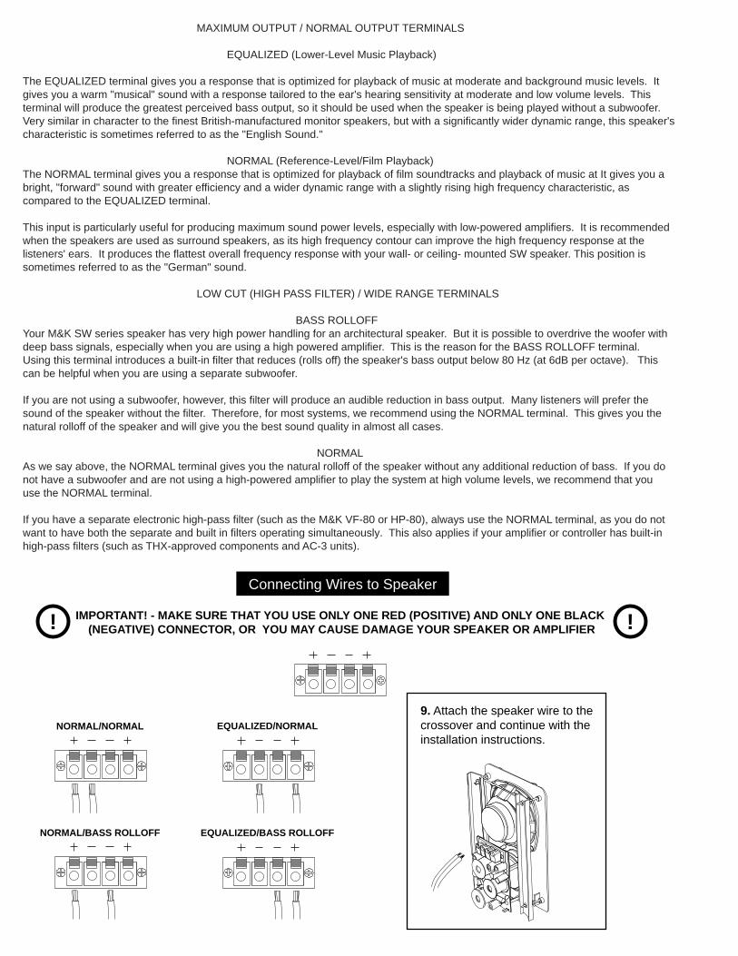
NORMAL/NORMAL
NORMAL/BASS ROLLOFF
EQUALIZED/NORMAL
EQUALIZED/BASS ROLLOFF
9. Attach the speaker wire to the crossover and continue with theinstallation instructions.
Connecting Wires to Speaker
! !IMPORTANT! - MAKE SURE THAT YOU USE ONLY ONE RED (POSITIVE) AND ONLY ONE BLACK (NEGATIVE) CONNECTOR, OR YOU MAY CAUSE DAMAGE YOUR SPEAKER OR AMPLIFIER
MAXIMUM OUTPUT / NORMAL OUTPUT TERMINALS
EQUALIZED (Lower-Level Music Playback)
The EQUALIZED terminal gives you a response that is optimized for playback of music at moderate and background music levels. It gives you a warm "musical" sound with a response tailored to the ear's hearing sensitivity at moderate and low volume levels. This terminal will produce the greatest perceived bass output, so it should be used when the speaker is being played without a subwoofer. Very similar in character to the finest British-manufactured monitor speakers, but with a significantly wider dynamic range, this speaker's characteristic is sometimes referred to as the "English Sound."
NORMAL (Reference-Level/Film Playback)The NORMAL terminal gives you a response that is optimized for playback of film soundtracks and playback of music at It gives you a bright, "forward" sound with greater efficiency and a wider dynamic range with a slightly rising high frequency characteristic, as compared to the EQUALIZED terminal.
This input is particularly useful for producing maximum sound power levels, especially with low-powered amplifiers. It is recommended when the speakers are used as surround speakers, as its high frequency contour can improve the high frequency response at the listeners' ears. It produces the flattest overall frequency response with your wall- or ceiling- mounted SW speaker. This position is sometimes referred to as the "German" sound.
LOW CUT (HIGH PASS FILTER) / WIDE RANGE TERMINALS
BASS ROLLOFFYour M&K SW series speaker has very high power handling for an architectural speaker. But it is possible to overdrive the woofer with deep bass signals, especially when you are using a high powered amplifier. This is the reason for the BASS ROLLOFF terminal. Using this terminal introduces a built-in filter that reduces (rolls off) the speaker's bass output below 80 Hz (at 6dB per octave). This can be helpful when you are using a separate subwoofer.
If you are not using a subwoofer, however, this filter will produce an audible reduction in bass output. Many listeners will prefer the sound of the speaker without the filter. Therefore, for most systems, we recommend using the NORMAL terminal. This gives you the natural rolloff of the speaker and will give you the best sound quality in almost all cases.
NORMALAs we say above, the NORMAL terminal gives you the natural rolloff of the speaker without any additional reduction of bass. If you do not have a subwoofer and are not using a high-powered amplifier to play the system at high volume levels, we recommend that you use the NORMAL terminal.
If you have a separate electronic high-pass filter (such as the M&K VF-80 or HP-80), always use the NORMAL terminal, as you do not want to have both the separate and built in filters operating simultaneously. This also applies if your amplifier or controller has built-in high-pass filters (such as THX-approved components and AC-3 units).

10. Remove packing material and grille from speaker. Do not remove the elastic cord! Make sure that the mounting screws are flush with the front baffle as shown.
11. Angle the speaker toward the wall and slip the bottom portion of the mounting arms into the wall opening.
12. Tip the unit vertically and pass the top edge of the mounting arms through the wall opening, allowing the unit to rest onthe bottom mounting screws.
MAKE SURE THE TWEETER IS TOWARDTHE BOTTOM!
mounting screws(4 total)
elastic cord
mounting arms
13. Raise the unit and press it toward the wall until it rests on the metal flanges and is flush with the wall.
Mounting Your New Speaker in the Wall
(4)
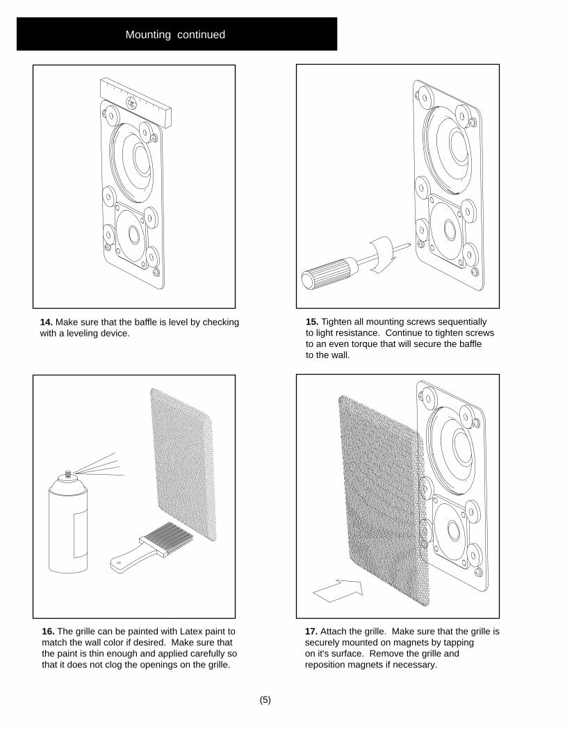
15. Tighten all mounting screws sequentiallyto light resistance. Continue to tighten screws to an even torque that will secure the baffleto the wall.
17. Attach the grille. Make sure that the grille issecurely mounted on magnets by tappingon it's surface. Remove the grille andreposition magnets if necessary.
16. The grille can be painted with Latex paint tomatch the wall color if desired. Make sure that the paint is thin enough and applied carefully so that it does not clog the openings on the grille.
(5)
14. Make sure that the baffle is level by checkingwith a leveling device.
Mounting continued
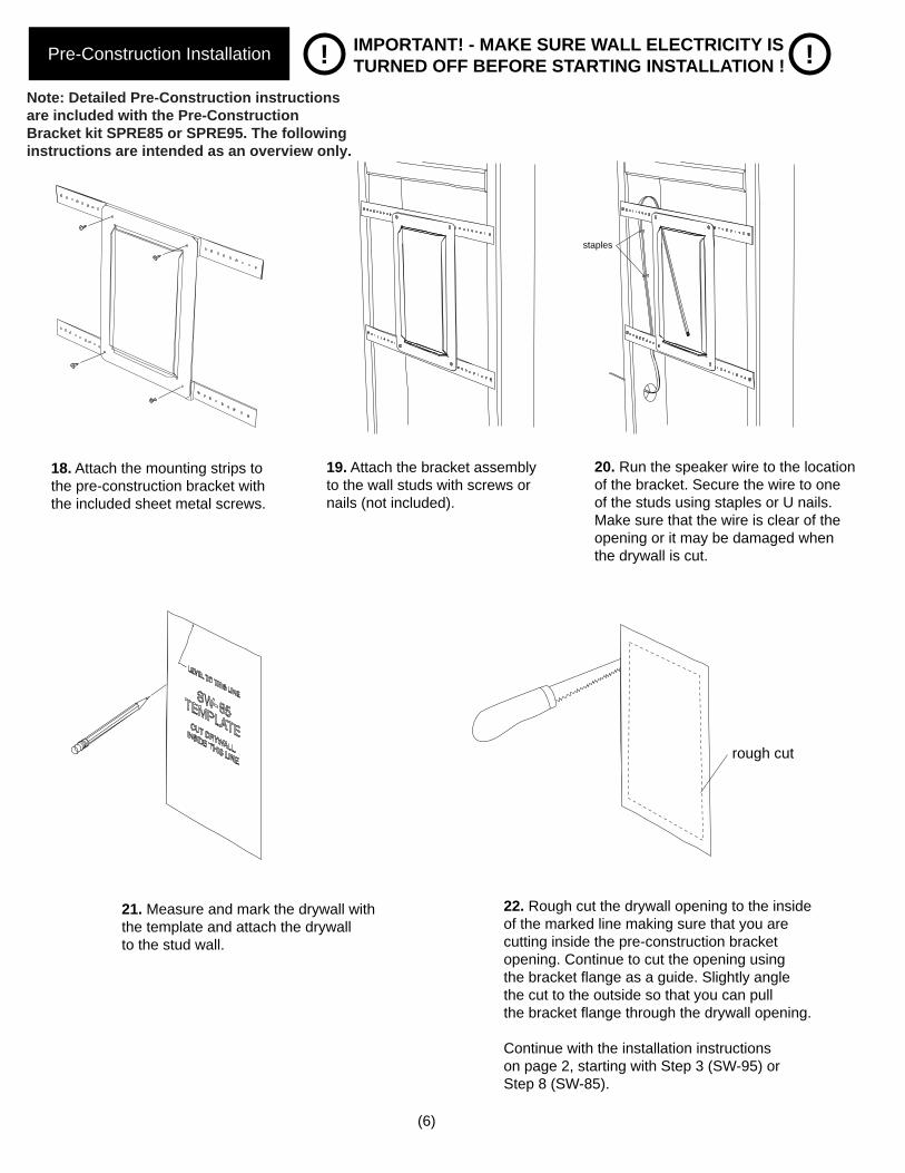
Pre-Construction Installation ! !IMPORTANT! - MAKE SURE WALL ELECTRICITY ISTURNED OFF BEFORE STARTING INSTALLATION !
18. Attach the mounting strips to the pre-construction bracket with the included sheet metal screws.
19. Attach the bracket assembly to the wall studs with screws or nails (not included).
21. Measure and mark the drywall with the template and attach the drywallto the stud wall.
22. Rough cut the drywall opening to the insideof the marked line making sure that you arecutting inside the pre-construction bracketopening. Continue to cut the opening usingthe bracket flange as a guide. Slightly anglethe cut to the outside so that you can pullthe bracket flange through the drywall opening.
Continue with the installation instructionson page 2, starting with Step 3 (SW-95) orStep 8 (SW-85).
(6)
rough cut
20. Run the speaker wire to the locationof the bracket. Secure the wire to oneof the studs using staples or U nails. Make sure that the wire is clear of theopening or it may be damaged whenthe drywall is cut.
staples
Note: Detailed Pre-Construction instructionsare included with the Pre-Construction Bracket kit SPRE85 or SPRE95. The following instructions are intended as an overview only.
(7)
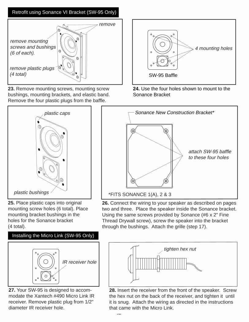
Sonance New Construction Bracket*
attach SW-95 baffleto these four holes
23. Remove mounting screws, mounting screw bushings, mounting brackets, and elastic band. Remove the four plastic plugs from the baffle.
remove
remove mountingscrews and bushings(6 of each).
remove plastic plugs(4 total)
25. Place plastic caps into original mounting screw holes (6 total). Placemounting bracket bushings in the holes for the Sonance bracket (4 total).
26. Connect the wiring to your speaker as described on pages two and three. Place the speaker inside the Sonance bracket. Using the same screws provided by Sonance (#6 x 2" Fine Thread Drywall screw), screw the speaker into the bracket through the bushings. Attach the grille (step 17).
Retrofit using Sonance VI Bracket (SW-95 Only)
plastic caps
plastic bushings
SW-95 Baffle
*FITS SONANCE 1(A), 2 & 3
Installing the Micro Link (SW-95 Only)
27. Your SW-95 is designed to accom-modate the Xantech #490 Micro Link IR receiver. Remove plastic plug from 1/2" diameter IR receiver hole.
28. Insert the receiver from the front of the speaker. Screwthe hex nut on the back of the receiver, and tighten it untilit is snug. Attach the wiring as directed in the instructions that came with the Micro Link.
IR receiver hole
tighten hex nut
24. Use the four holes shown to mount to the Sonance Bracket
4 mounting holes
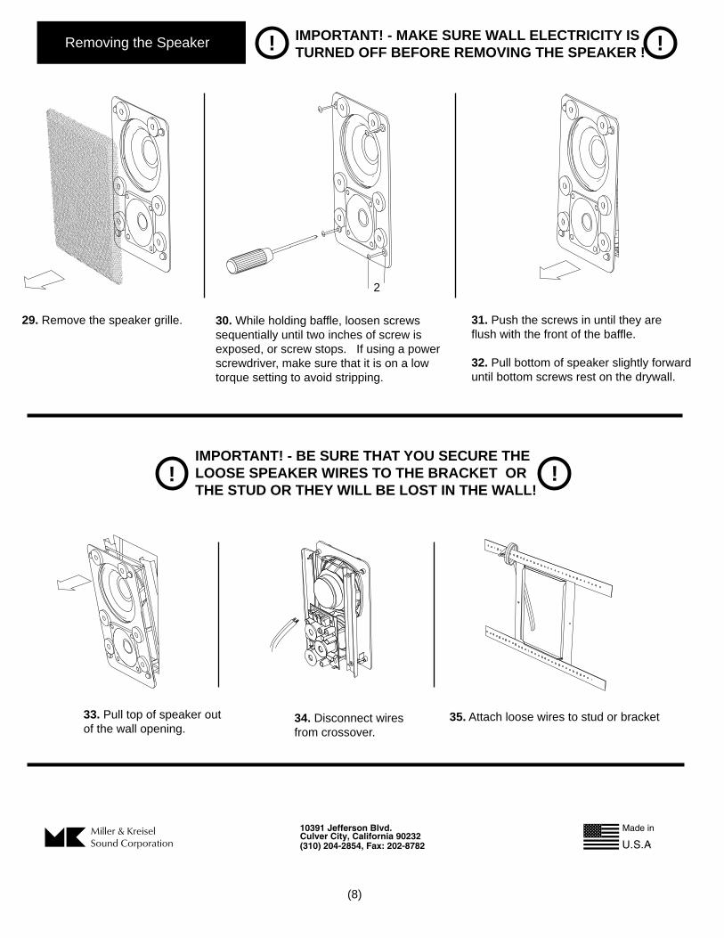
Removing the Speaker ! !IMPORTANT! - MAKE SURE WALL ELECTRICITY ISTURNED OFF BEFORE REMOVING THE SPEAKER !
! !IMPORTANT! - BE SURE THAT YOU SECURE THE LOOSE SPEAKER WIRES TO THE BRACKET ORTHE STUD OR THEY WILL BE LOST IN THE WALL!
29. Remove the speaker grille. 30. While holding baffle, loosen screws sequentially until two inches of screw is exposed, or screw stops. If using a powerscrewdriver, make sure that it is on a low torque setting to avoid stripping.
2
31. Push the screws in until they are flush with the front of the baffle.
32. Pull bottom of speaker slightly forward until bottom screws rest on the drywall.
33. Pull top of speaker outof the wall opening.
34. Disconnect wiresfrom crossover.
35. Attach loose wires to stud or bracket
(8)