Embed Size (px)
Citation preview
Suzuki V-Strom DL1000 Clutch Basket
Removal and Re-fitting
Original pictures by Daniel M. O'Brien, 2003
Converted to PowerPoint by Janice Clanfield, 2008,
Updated and further pictures added by John Sykes
Sharealike or svman on the forums 2012.
Also suitable for use with the
Suzuki SV1000 – very similar.
Downloaded from

Introduction
Some of the following slides were first put together by Daniel M. O'Brien and later
converted to PowerPoint by Janice Clanfield. I would like to thank them and hope they are
happy with the changes.
Since their launch in 2002 right up to 2009, owners have found the clutch baskets in the
Suzuki V-Strom DL1000 to cause a harsh engine vibration while riding. It became known as
the “chudder” – part shudder and part chatter. There was also some unpleasant noise at
idle. It was thought the only cure was a new clutch basket or to fit the later Suzuki SV1000
basket. By 2009 there was evidence that neither of these was a reliable cure as the
vibrations all too often returned.
Since 2009 many owners have been removing and re-fitting their bikes original clutch
basket after they had been re-engineered. Over the years some of these owners either
asked for clarification or gave feedback after following the original slides. I began to revise
and included new slides as required responding to the feedback. Now in late 2012, the fully
revised slides have been available for six months, so I am looking to make them available
to all for download. Hope they prove as helpful in taking owners through the job as the
originals. Always glad of feedback to improve them further.
Thank you to all who contributed.
Sharealike aka Svman. John Sykes [email protected]
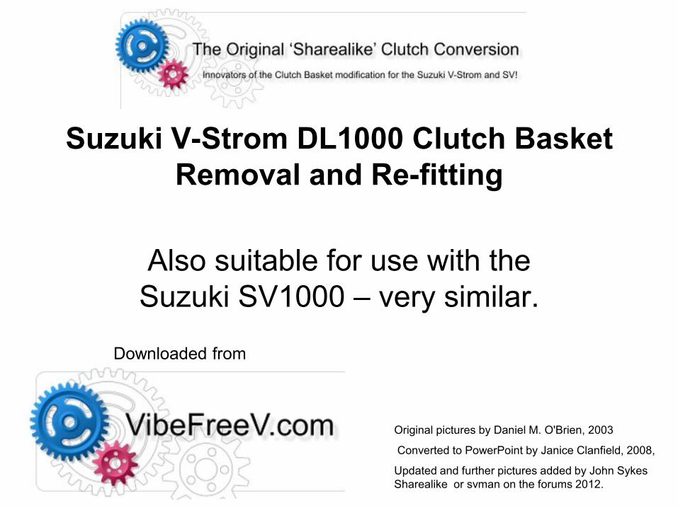
The centre stand or a paddock/race stand is good. Straight up position is best for draining fluids.
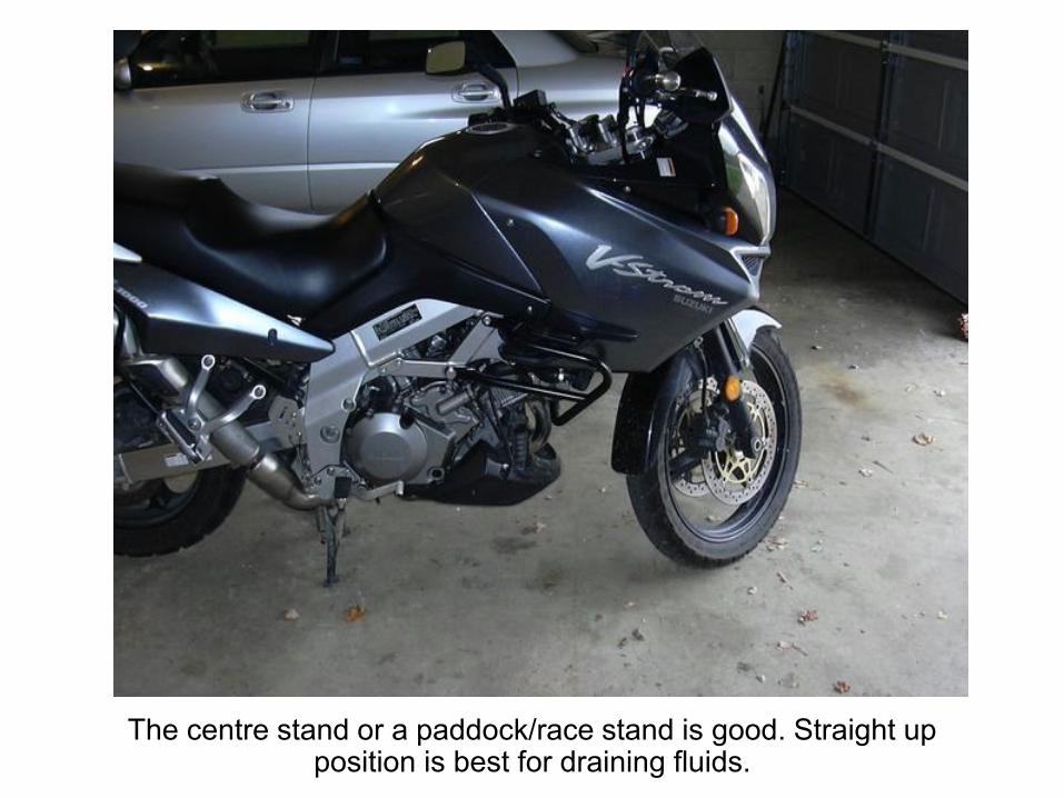
This is the clutch side of the engine case, where the sight glass is.
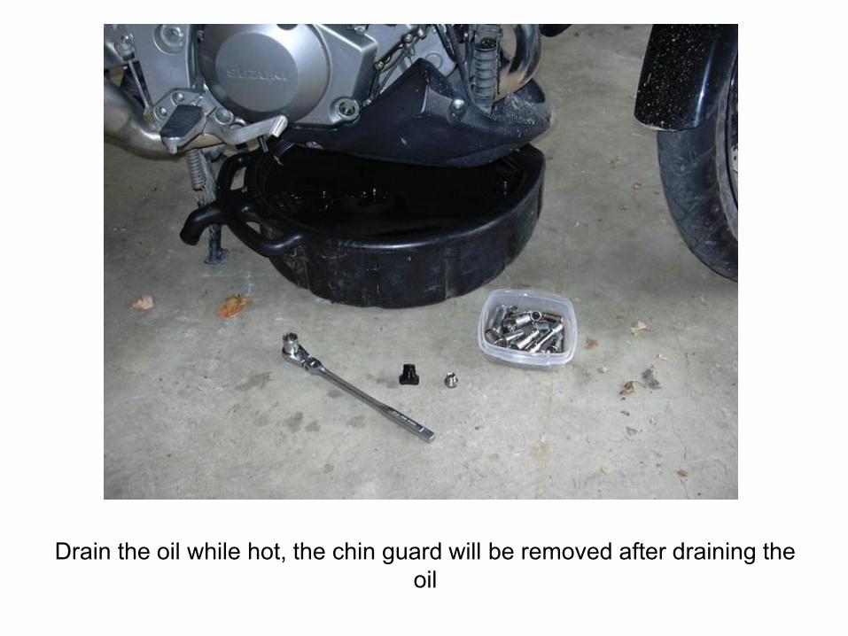
Drain the oil while hot, the chin guard will be removed after draining the
oil

Remove the nose piece, and right side fairing, the engine guards keep
the fairing from coming off easily, so best remove the black piece from
the fairing first. Not required for SV.
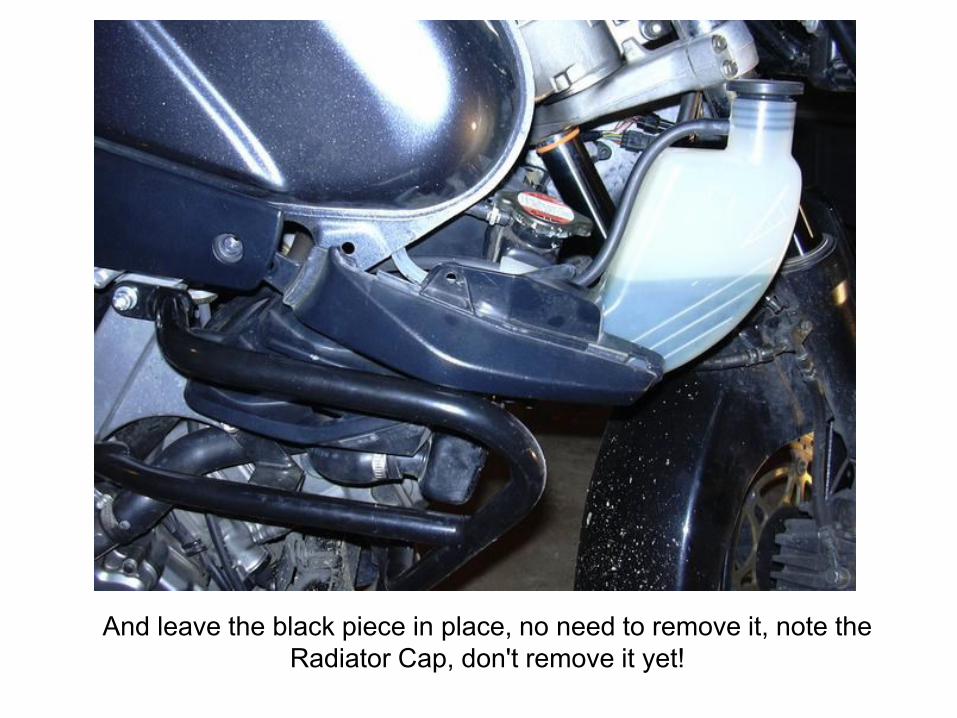
And leave the black piece in place, no need to remove it, note the
Radiator Cap, don't remove it yet!
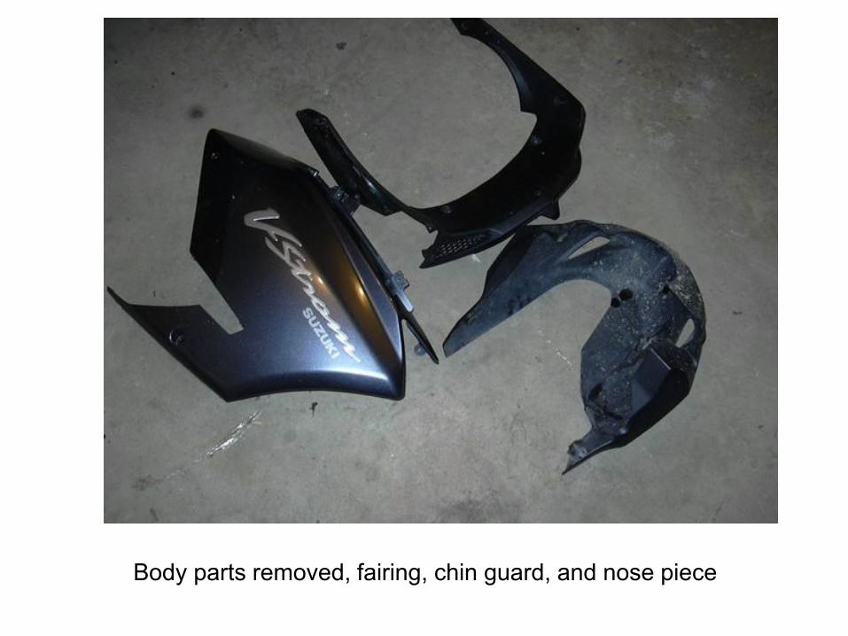
Body parts removed, fairing, chin guard, and nose piece
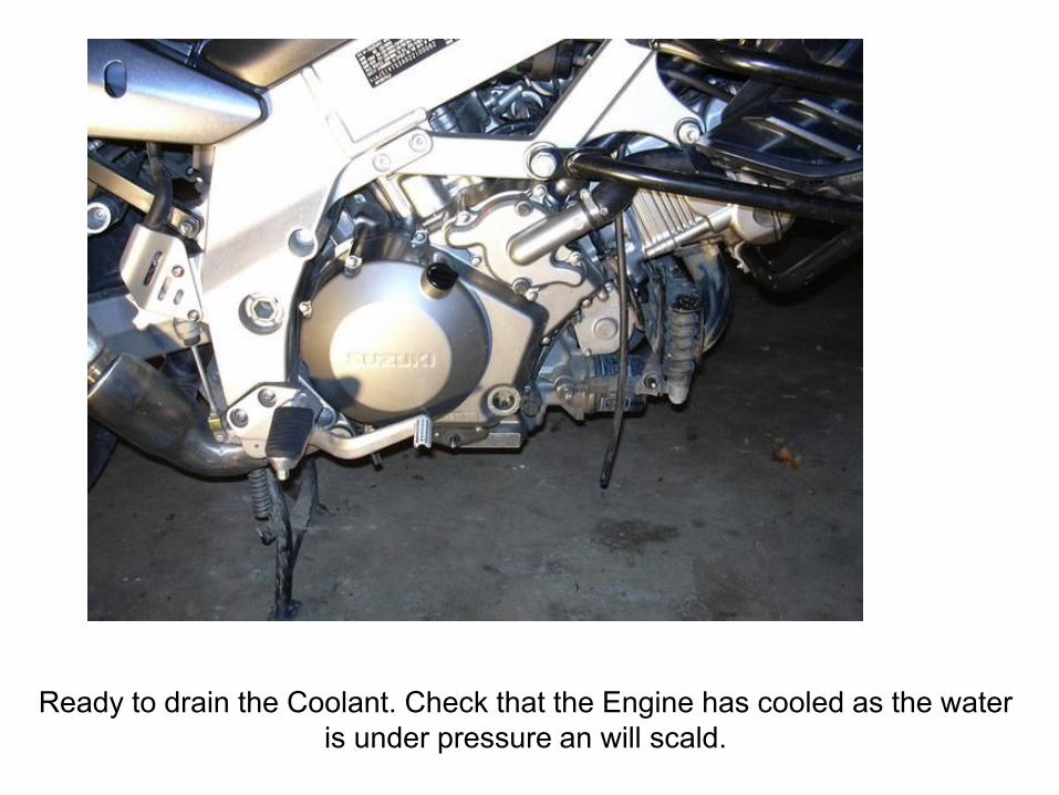
Ready to drain the Coolant. Check that the Engine has cooled as the water
is under pressure an will scald.
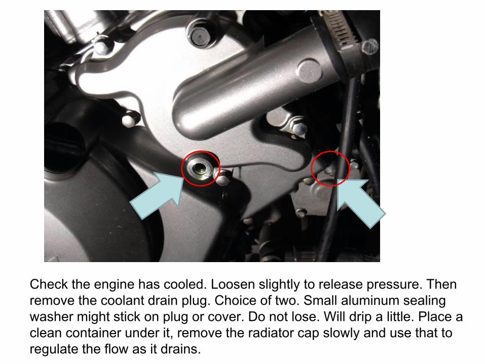
Check the engine has cooled. Loosen slightly to release pressure. Then
remove the coolant drain plug. Choice of two. Small aluminum sealing
washer might stick on plug or cover. Do not lose. Will drip a little. Place a
clean container under it, remove the radiator cap slowly and use that to
regulate the flow as it drains.
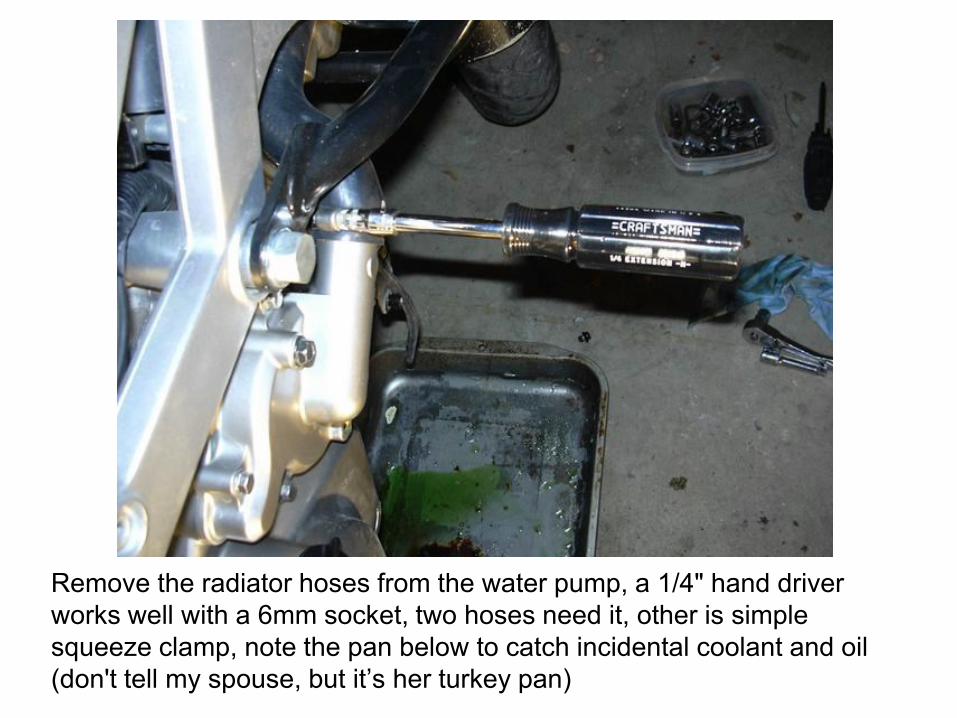
Remove the radiator hoses from the water pump, a 1/4" hand driver
works well with a 6mm socket, two hoses need it, other is simple
squeeze clamp, note the pan below to catch incidental coolant and oil
(don't tell my spouse, but it’s her turkey pan)
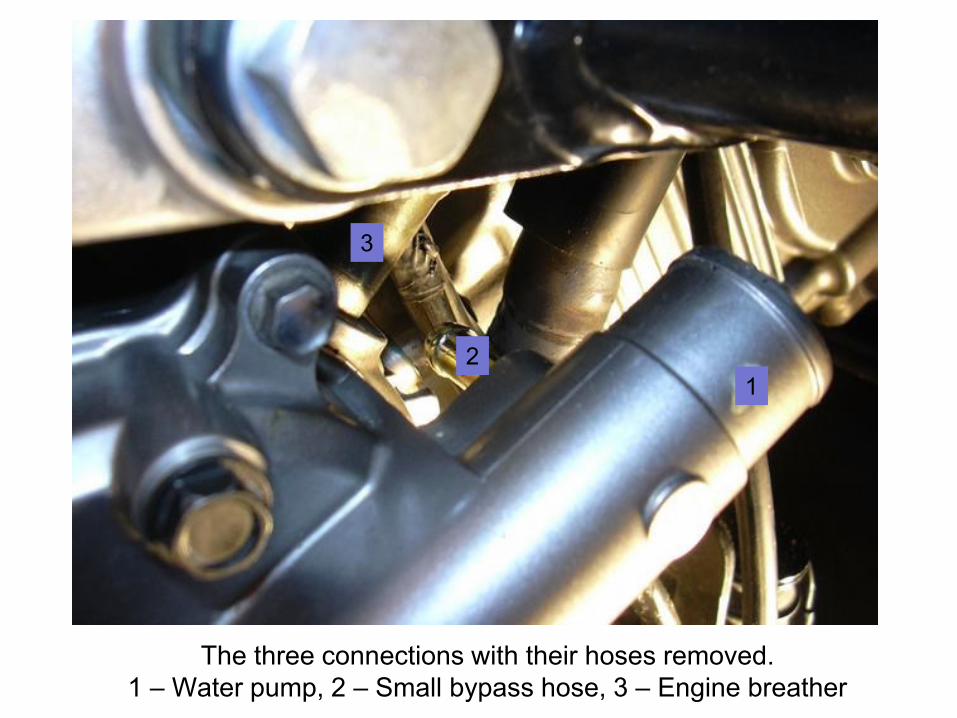
The three connections with their hoses removed.
1 – Water pump, 2 – Small bypass hose, 3 – Engine breather
1
2
3
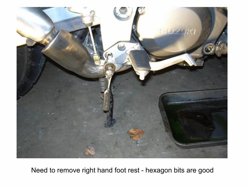
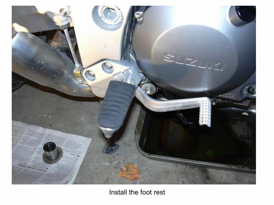
Need to remove right hand foot rest - hexagon bits are good
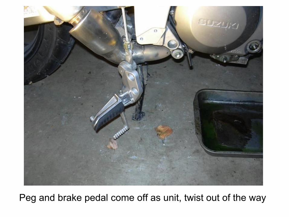
Peg and brake pedal come off as unit, twist out of the way
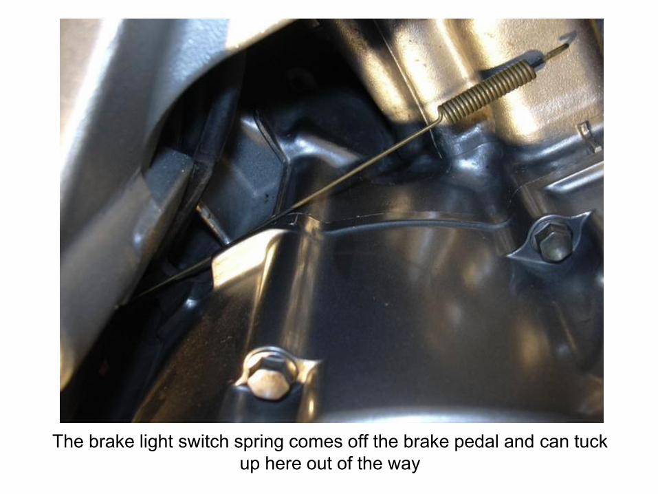
The brake light switch spring comes off the brake pedal and can tuck
up here out of the way
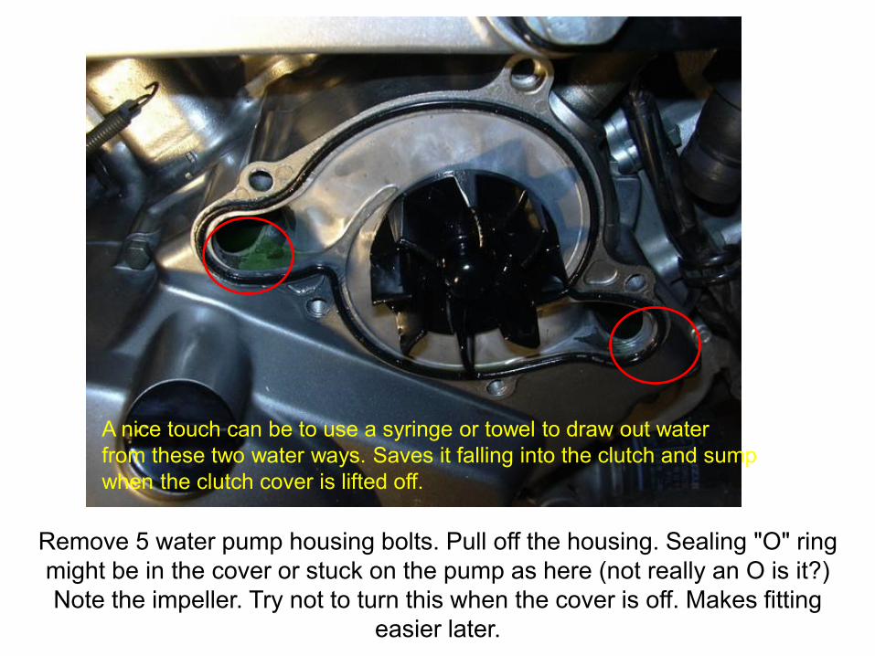
Remove 5 water pump housing bolts. Pull off the housing. Sealing "O" ring
might be in the cover or stuck on the pump as here (not really an O is it?)
Note the impeller. Try not to turn this when the cover is off. Makes fitting
easier later.
A nice touch can be to use a syringe or towel to draw out water
from these two water ways. Saves it falling into the clutch and sump
when the clutch cover is lifted off.
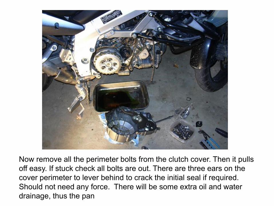
Now remove all the perimeter bolts from the clutch cover. Then it pulls
off easy. If stuck check all bolts are out. There are three ears on the
cover perimeter to lever behind to crack the initial seal if required.
Should not need any force. There will be some extra oil and water
drainage, thus the pan
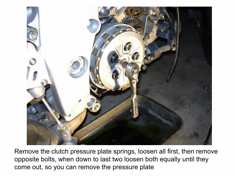
Remove the clutch pressure plate springs, loosen all first, then remove
opposite bolts, when down to last two loosen both equally until they
come out, so you can remove the pressure plate
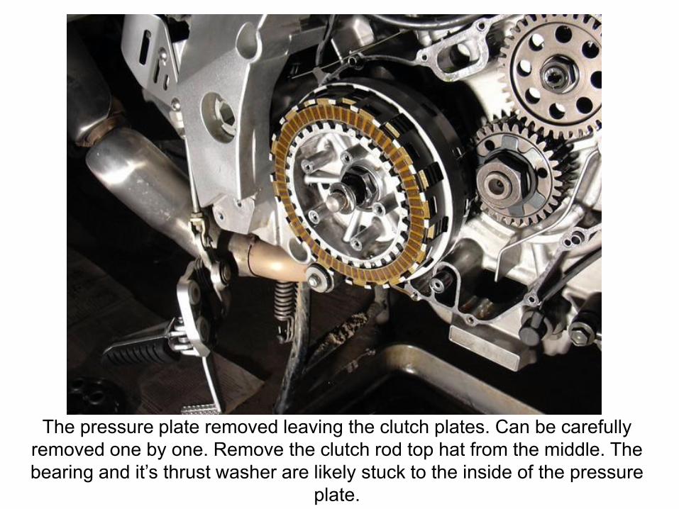
The pressure plate removed leaving the clutch plates. Can be carefully
removed one by one. Remove the clutch rod top hat from the middle. The
bearing and it’s thrust washer are likely stuck to the inside of the pressure
plate.
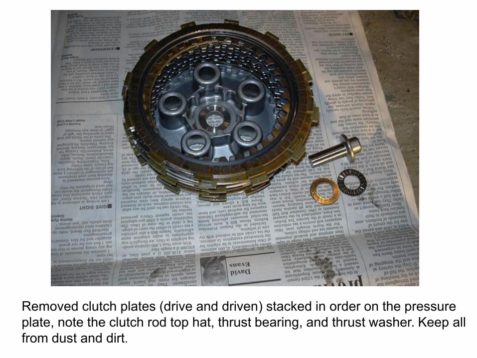
Removed clutch plates (drive and driven) stacked in order on the pressure
plate, note the clutch rod top hat, thrust bearing, and thrust washer. Keep all
from dust and dirt.
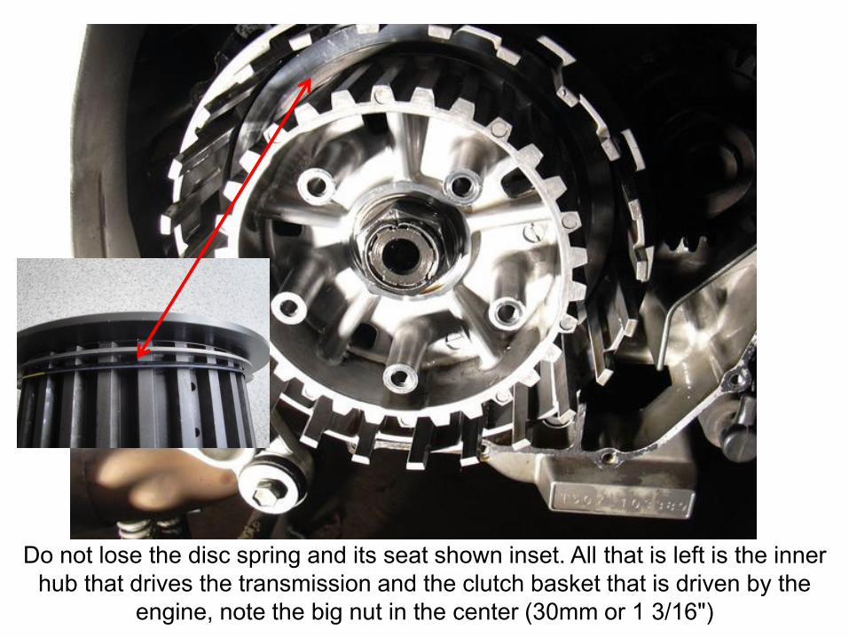
Do not lose the disc spring and its seat shown inset. All that is left is the inner
hub that drives the transmission and the clutch basket that is driven by the
engine, note the big nut in the center (30mm or 1 3/16")
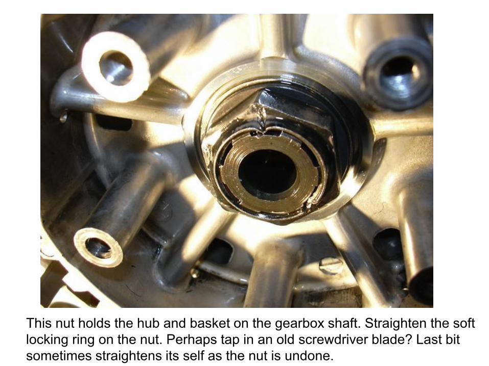
This nut holds the hub and basket on the gearbox shaft. Straighten the soft
locking ring on the nut. Perhaps tap in an old screwdriver blade? Last bit
sometimes straightens its self as the nut is undone.
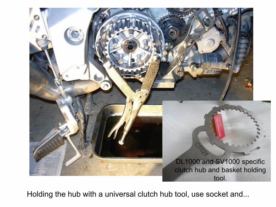
Holding the hub with a universal clutch hub tool, use socket and...
DL1000 and SV1000 specific
clutch hub and basket holding
tool.
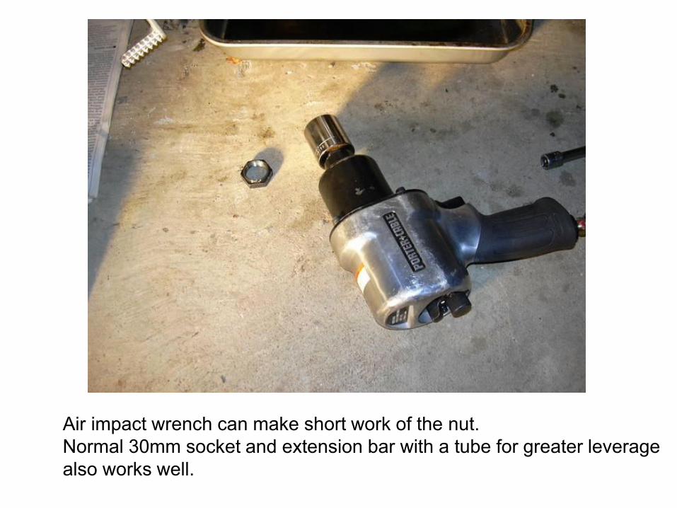
Air impact wrench can make short work of the nut.
Normal 30mm socket and extension bar with a tube for greater leverage
also works well.
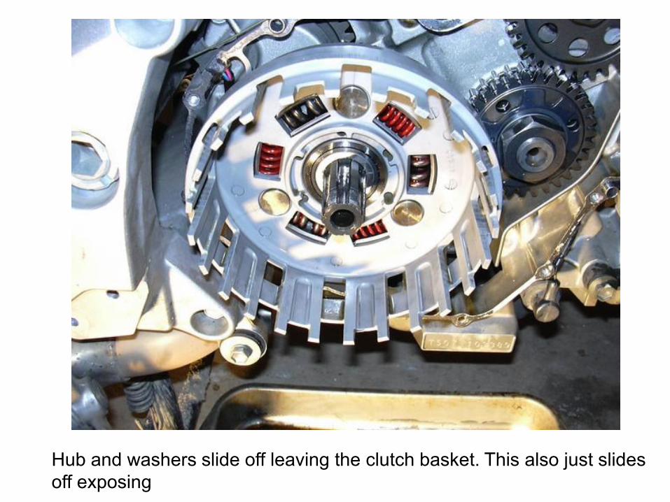
Hub and washers slide off leaving the clutch basket. This also just slides
off exposing
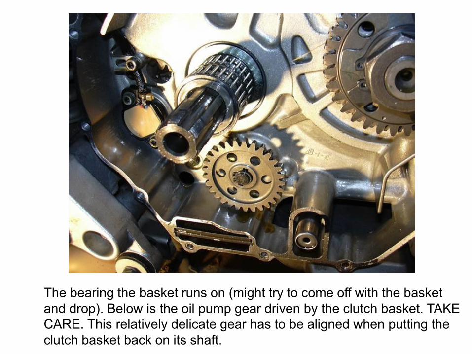
The bearing the basket runs on (might try to come off with the basket
and drop). Below is the oil pump gear driven by the clutch basket. TAKE
CARE. This relatively delicate gear has to be aligned when putting the
clutch basket back on its shaft.
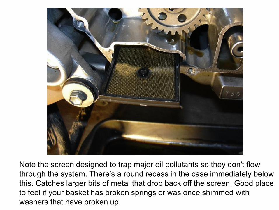
Note the screen designed to trap major oil pollutants so they don't flow
through the system. There’s a round recess in the case immediately below
this. Catches larger bits of metal that drop back off the screen. Good place
to feel if your basket has broken springs or was once shimmed with
washers that have broken up.
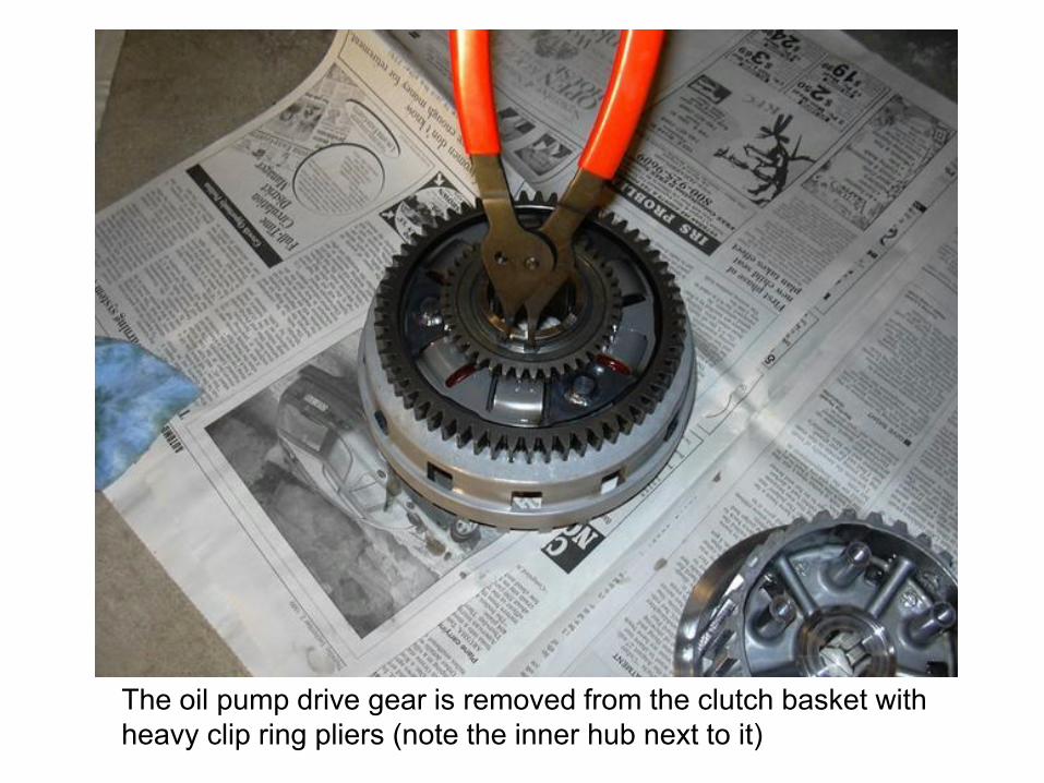
The oil pump drive gear is removed from the clutch basket with
heavy clip ring pliers (note the inner hub next to it)
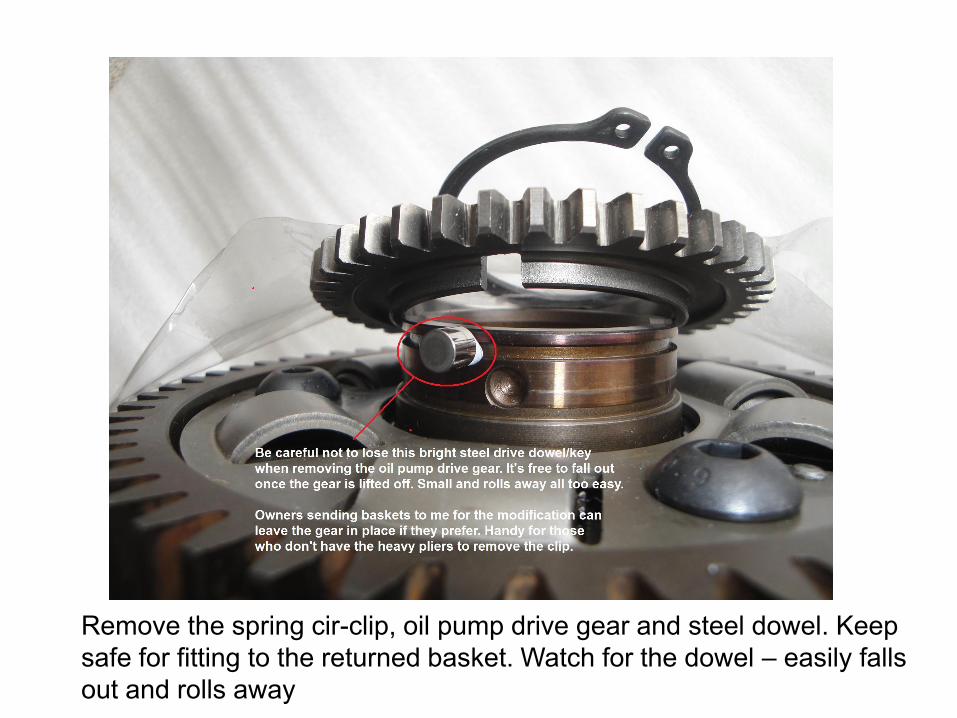
Remove the spring cir-clip, oil pump drive gear and steel dowel. Keep
safe for fitting to the returned basket. Watch for the dowel – easily falls
out and rolls away
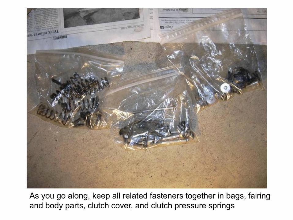
As you go along, keep all related fasteners together in bags, fairing
and body parts, clutch cover, and clutch pressure springs
For the installation it can help to use the Service Manual. Particularly if
the original order the clutch plates came out in has been lost.
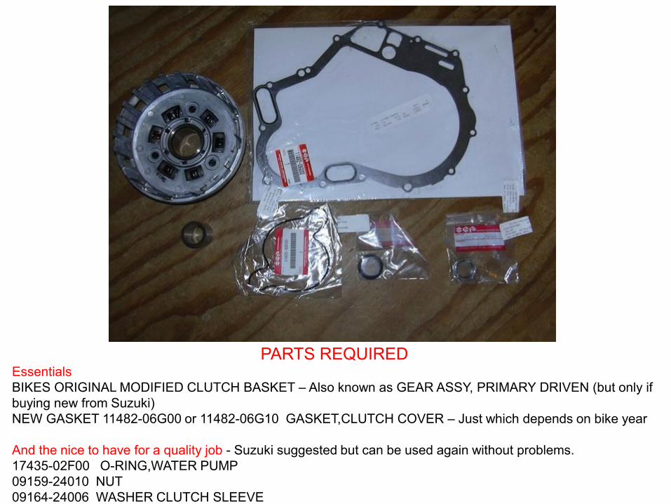
PARTS REQUIRED Essentials
BIKES ORIGINAL MODIFIED CLUTCH BASKET – Also known as GEAR ASSY, PRIMARY DRIVEN (but only if
buying new from Suzuki)
NEW GASKET 11482-06G00 or 11482-06G10 GASKET,CLUTCH COVER – Just which depends on bike year
And the nice to have for a quality job - Suzuki suggested but can be used again without problems.
17435-02F00 O-RING,WATER PUMP
09159-24010 NUT
09164-24006 WASHER CLUTCH SLEEVE
1
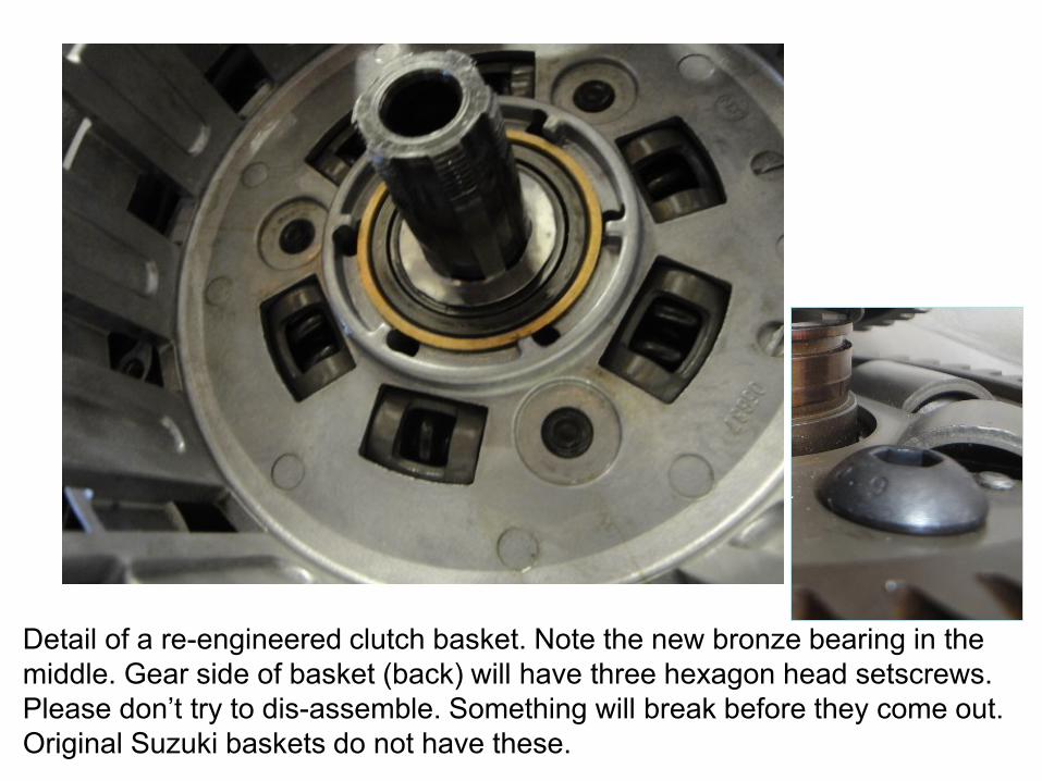
Detail of a re-engineered clutch basket. Note the new bronze bearing in the
middle. Gear side of basket (back) will have three hexagon head setscrews.
Please don’t try to dis-assemble. Something will break before they come out.
Original Suzuki baskets do not have these.
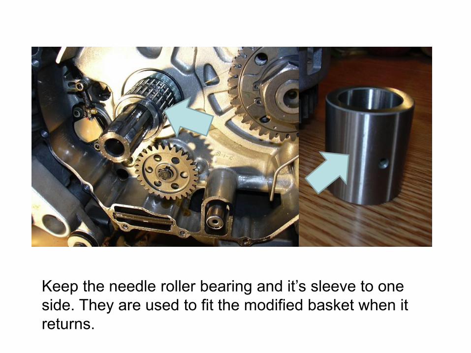
Keep the needle roller bearing and it’s sleeve to one
side. They are used to fit the modified basket when it
returns.
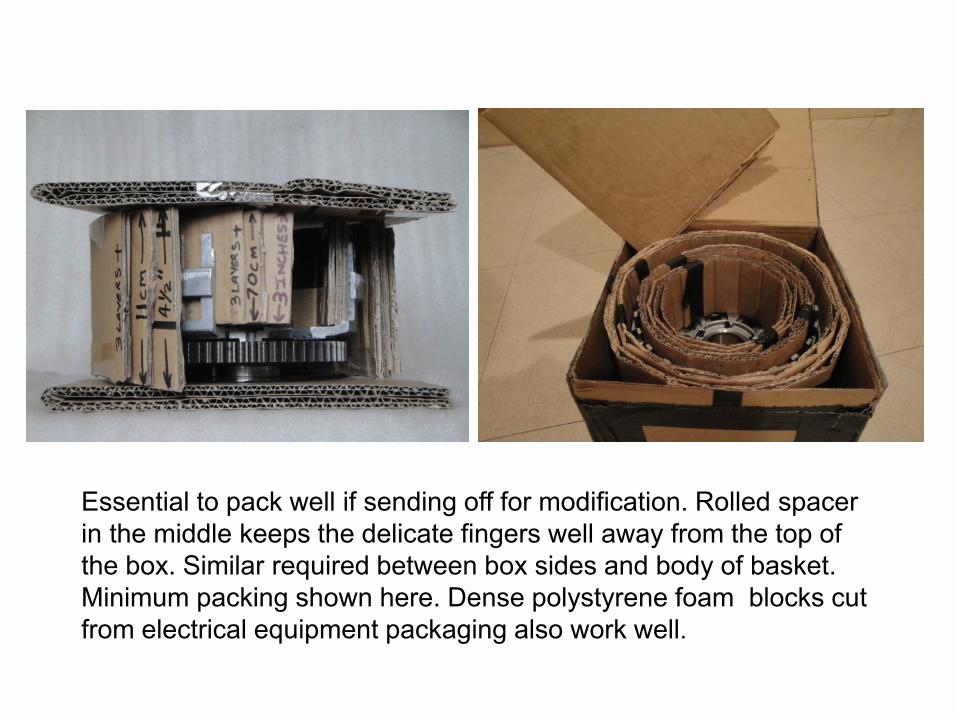
Essential to pack well if sending off for modification. Rolled spacer
in the middle keeps the delicate fingers well away from the top of
the box. Similar required between box sides and body of basket.
Minimum packing shown here. Dense polystyrene foam blocks cut
from electrical equipment packaging also work well.
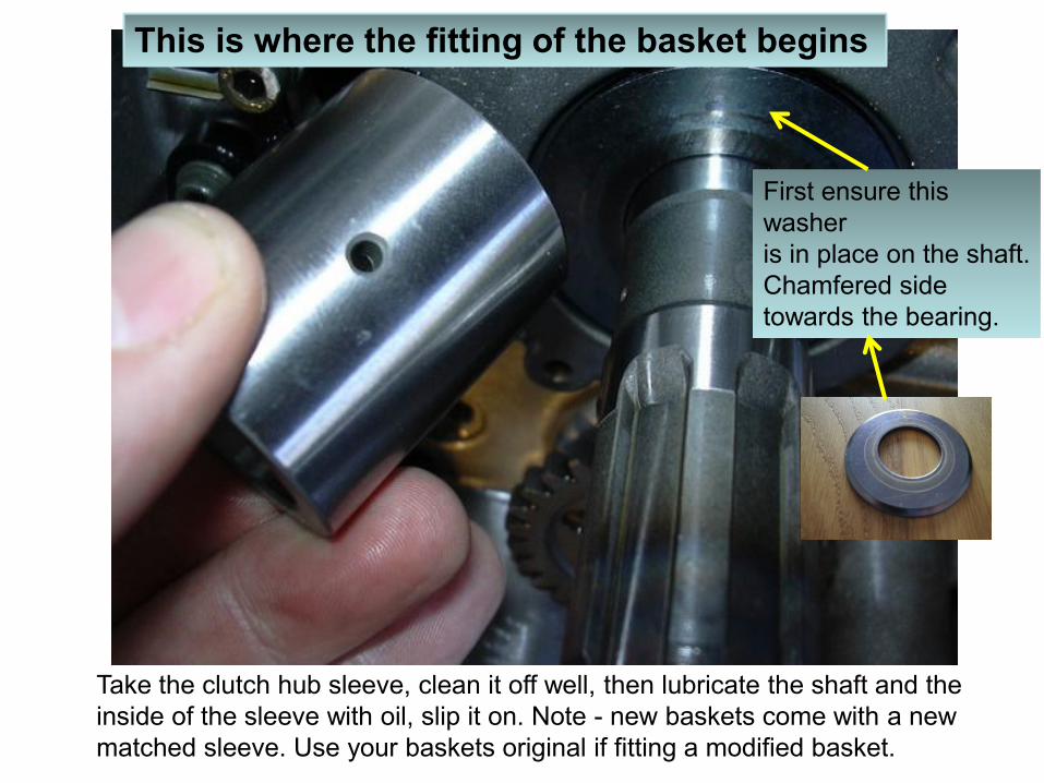
Take the clutch hub sleeve, clean it off well, then lubricate the shaft and the
inside of the sleeve with oil, slip it on. Note - new baskets come with a new
matched sleeve. Use your baskets original if fitting a modified basket.
This is where the fitting of the basket begins
First ensure this
washer
is in place on the shaft.
Chamfered side
towards the bearing.
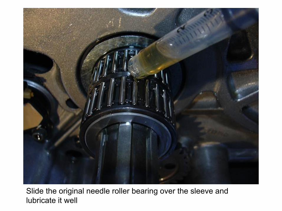
Slide the original needle roller bearing over the sleeve and
lubricate it well
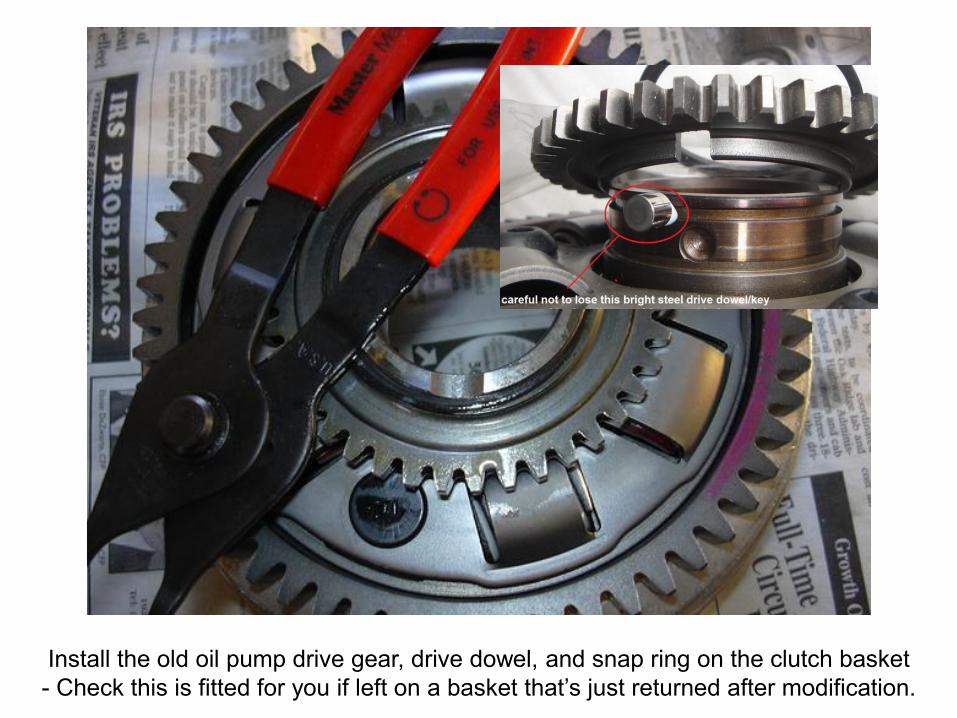
Install the old oil pump drive gear, drive dowel, and snap ring on the clutch basket
- Check this is fitted for you if left on a basket that’s just returned after modification.
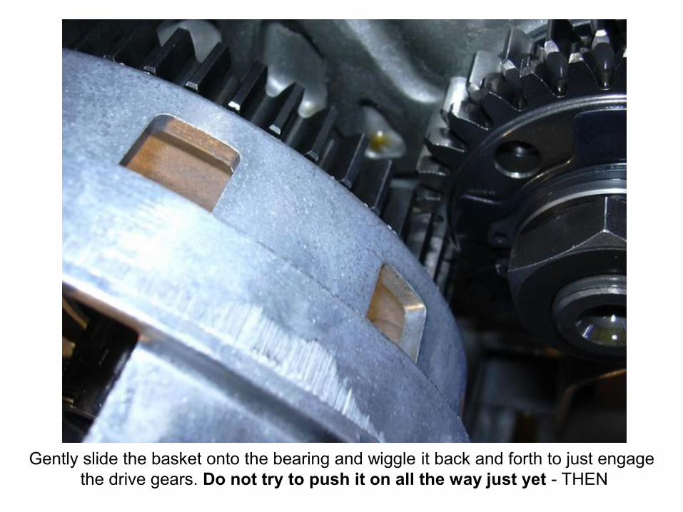
Gently slide the basket onto the bearing and wiggle it back and forth to just engage
the drive gears. Do not try to push it on all the way just yet - THEN
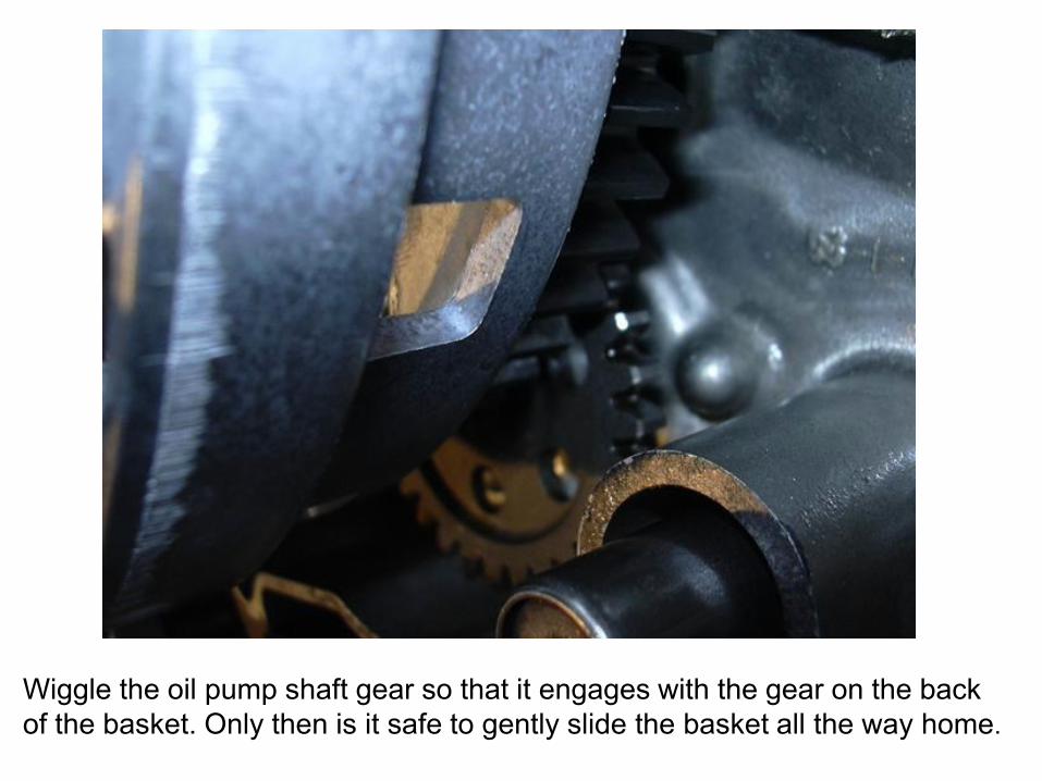
Wiggle the oil pump shaft gear so that it engages with the gear on the back
of the basket. Only then is it safe to gently slide the basket all the way home.
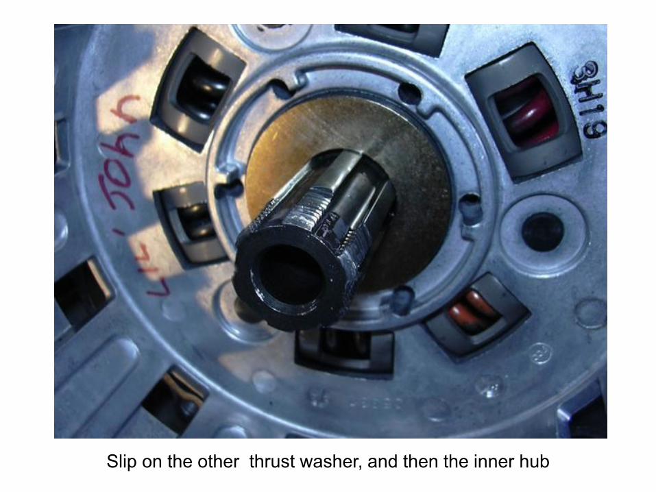
Slip on the other thrust washer, and then the inner hub
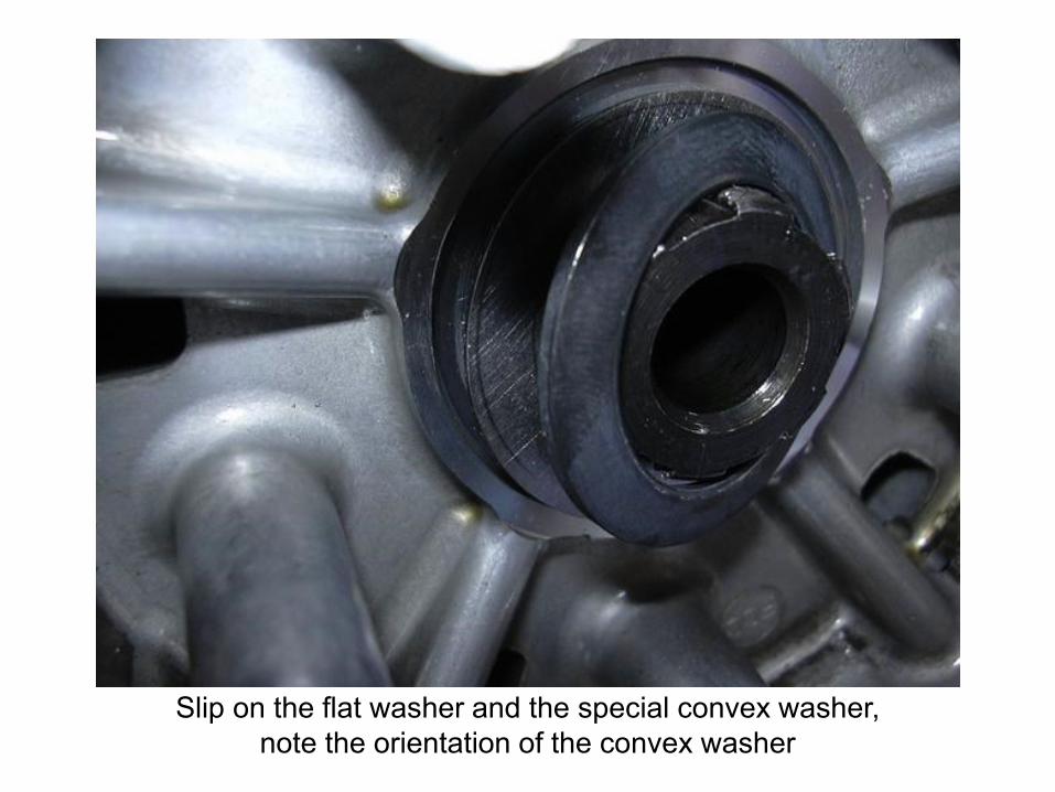
Slip on the flat washer and the special convex washer,
note the orientation of the convex washer
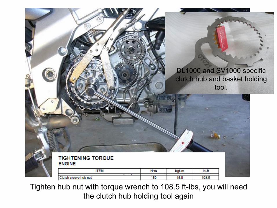
Tighten hub nut with torque wrench to 108.5 ft-lbs, you will need
the clutch hub holding tool again
DL1000 and SV1000 specific
clutch hub and basket holding
tool.
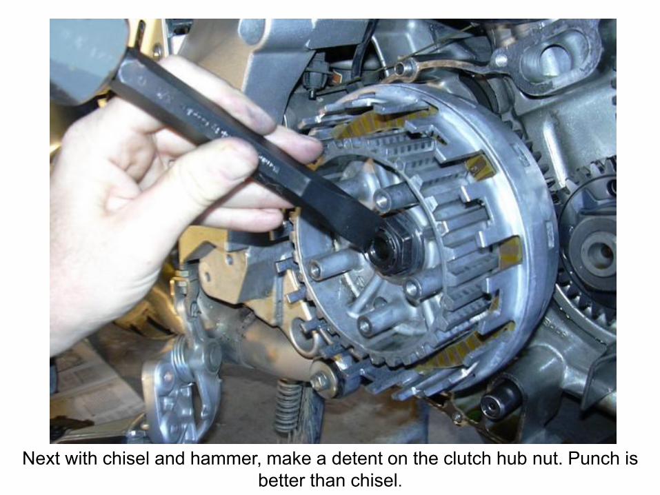
Next with chisel and hammer, make a detent on the clutch hub nut. Punch is
better than chisel.
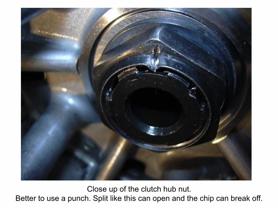
Close up of the clutch hub nut.
Better to use a punch. Split like this can open and the chip can break off.
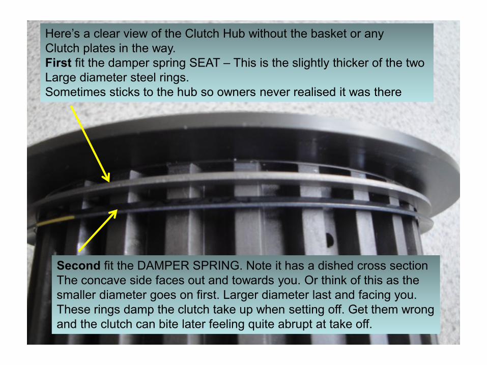
Here’s a clear view of the Clutch Hub without the basket or any
Clutch plates in the way.
First fit the damper spring SEAT – This is the slightly thicker of the two
Large diameter steel rings.
Sometimes sticks to the hub so owners never realised it was there
Second fit the DAMPER SPRING. Note it has a dished cross section
The concave side faces out and towards you. Or think of this as the
smaller diameter goes on first. Larger diameter last and facing you.
These rings damp the clutch take up when setting off. Get them wrong
and the clutch can bite later feeling quite abrupt at take off.
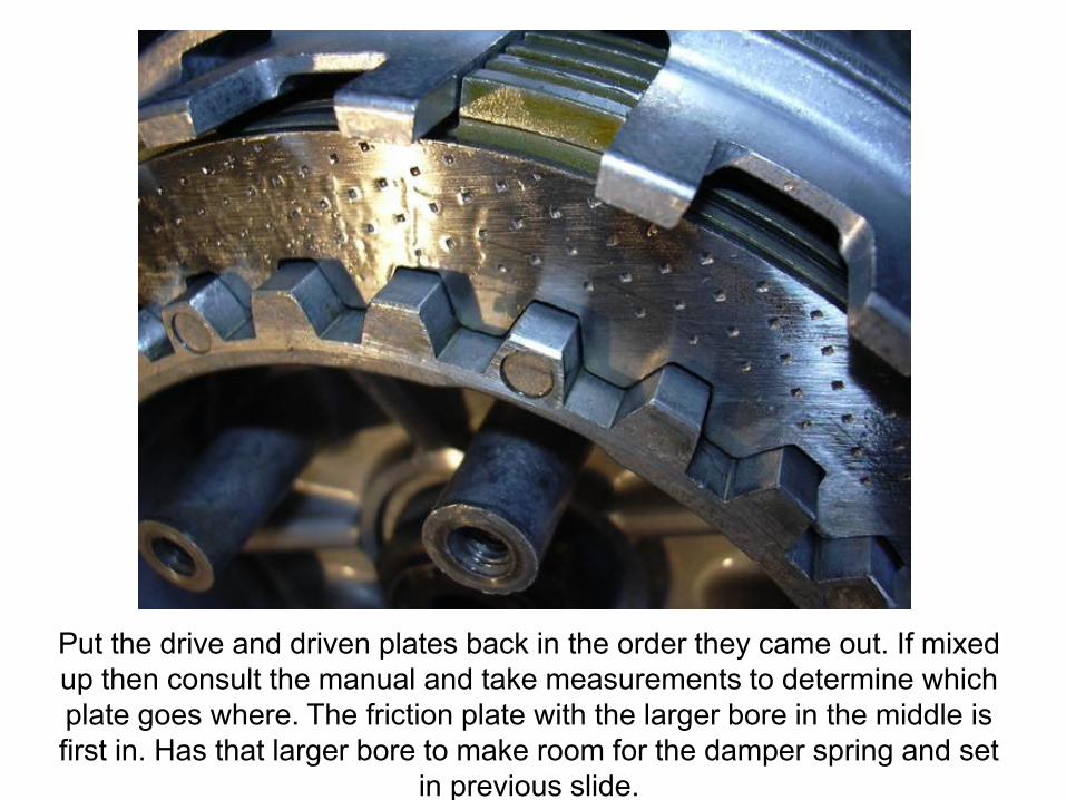
Put the drive and driven plates back in the order they came out. If mixed
up then consult the manual and take measurements to determine which
plate goes where. The friction plate with the larger bore in the middle is
first in. Has that larger bore to make room for the damper spring and set
in previous slide.
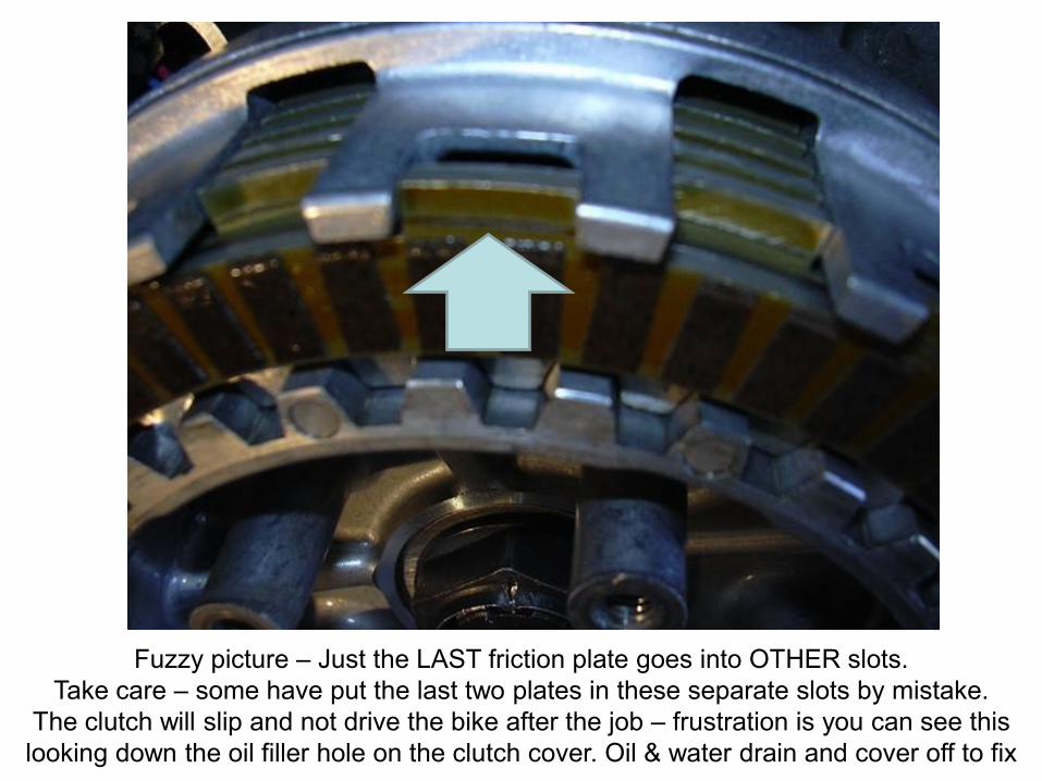
Fuzzy picture – Just the LAST friction plate goes into OTHER slots.
Take care – some have put the last two plates in these separate slots by mistake.
The clutch will slip and not drive the bike after the job – frustration is you can see this
looking down the oil filler hole on the clutch cover. Oil & water drain and cover off to fix
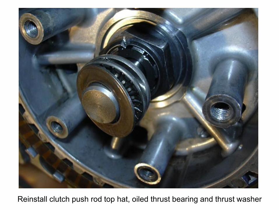
Reinstall clutch push rod top hat, oiled thrust bearing and thrust washer
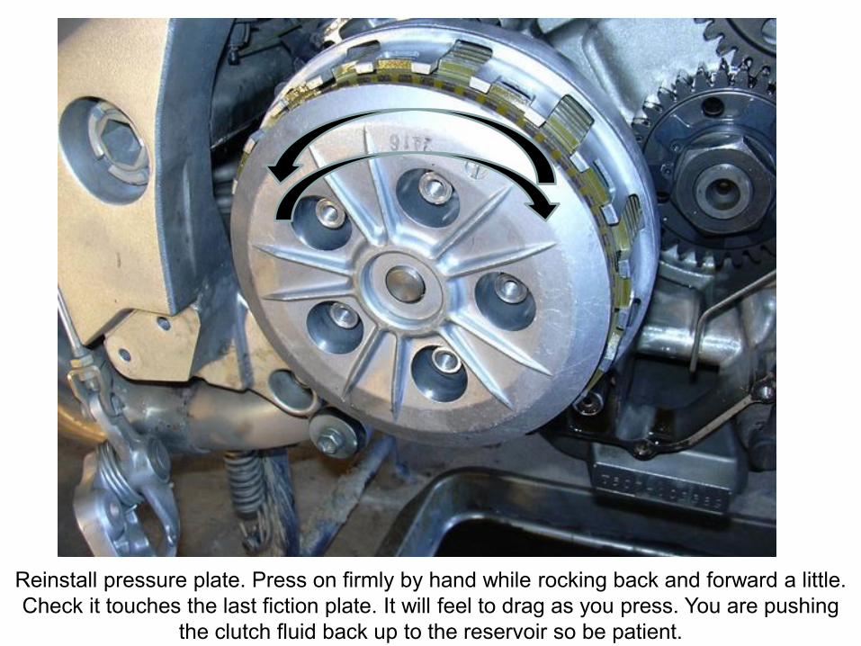
Reinstall pressure plate. Press on firmly by hand while rocking back and forward a little.
Check it touches the last fiction plate. It will feel to drag as you press. You are pushing
the clutch fluid back up to the reservoir so be patient.
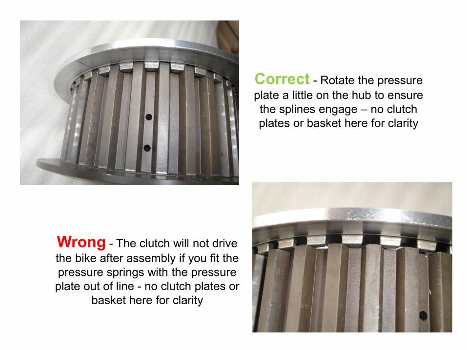
Correct - Rotate the pressure
plate a little on the hub to ensure
the splines engage – no clutch
plates or basket here for clarity
Wrong - The clutch will not drive
the bike after assembly if you fit the
pressure springs with the pressure
plate out of line - no clutch plates or
basket here for clarity
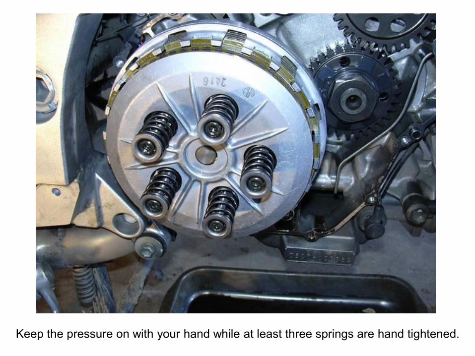
Keep the pressure on with your hand while at least three springs are hand tightened.
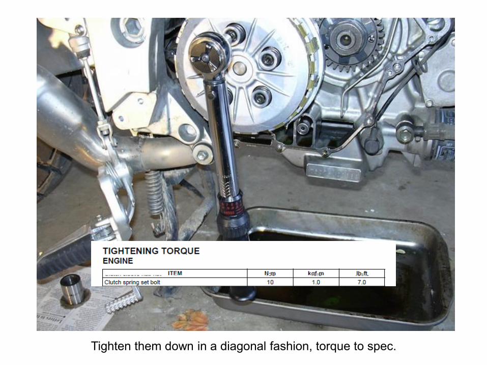
Tighten them down in a diagonal fashion, torque to spec.
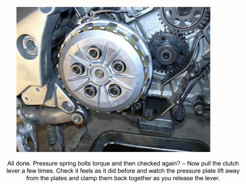
All done. Pressure spring bolts torque and then checked again? – Now pull the clutch
lever a few times. Check it feels as it did before and watch the pressure plate lift away
from the plates and clamp them back together as you release the lever.
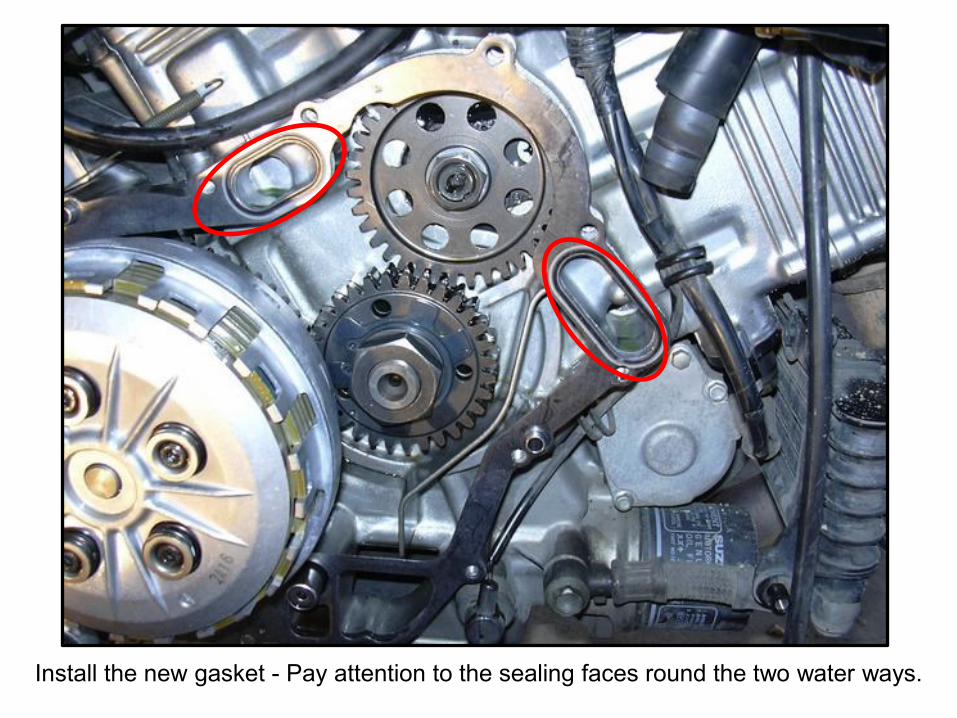
Install the new gasket - Pay attention to the sealing faces round the two water ways.
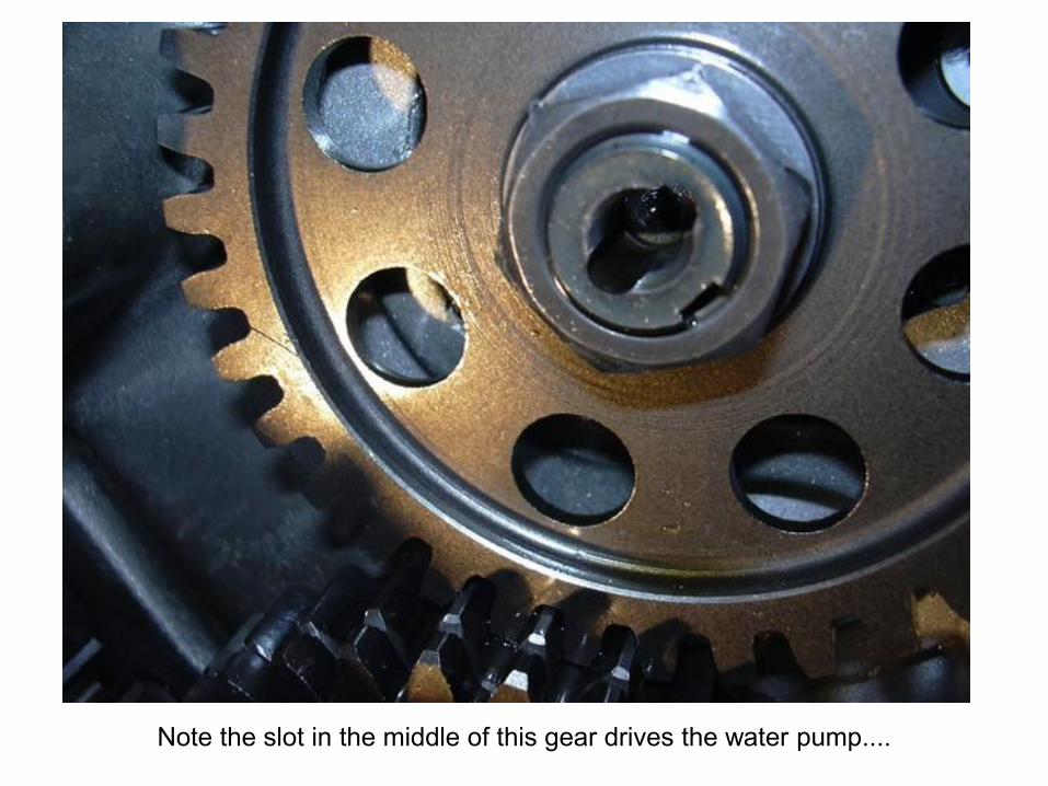
Note the slot in the middle of this gear drives the water pump....
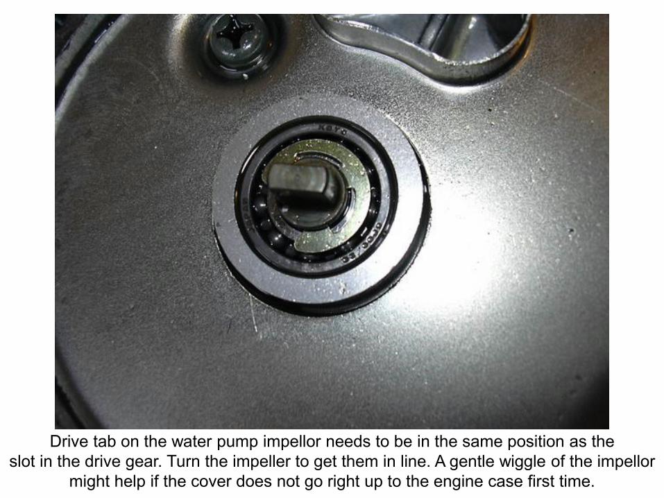
Drive tab on the water pump impellor needs to be in the same position as the
slot in the drive gear. Turn the impeller to get them in line. A gentle wiggle of the impellor
might help if the cover does not go right up to the engine case first time.
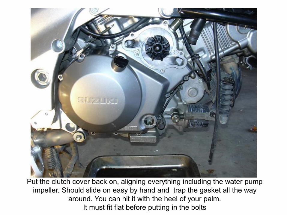
Put the clutch cover back on, aligning everything including the water pump
impeller. Should slide on easy by hand and trap the gasket all the way
around. You can hit it with the heel of your palm.
It must fit flat before putting in the bolts
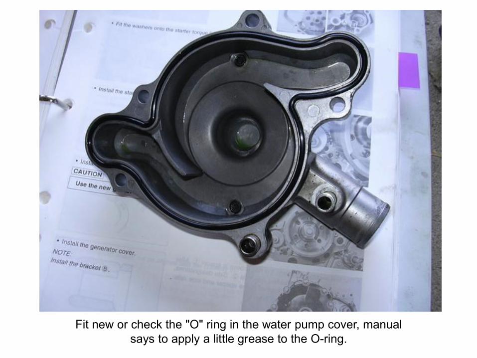
Fit new or check the "O" ring in the water pump cover, manual
says to apply a little grease to the O-ring.
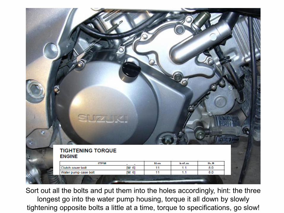
Sort out all the bolts and put them into the holes accordingly, hint: the three
longest go into the water pump housing, torque it all down by slowly
tightening opposite bolts a little at a time, torque to specifications, go slow!
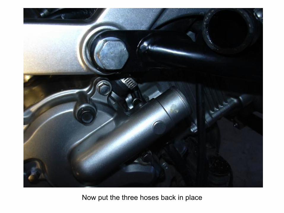
Now put the three hoses back in place
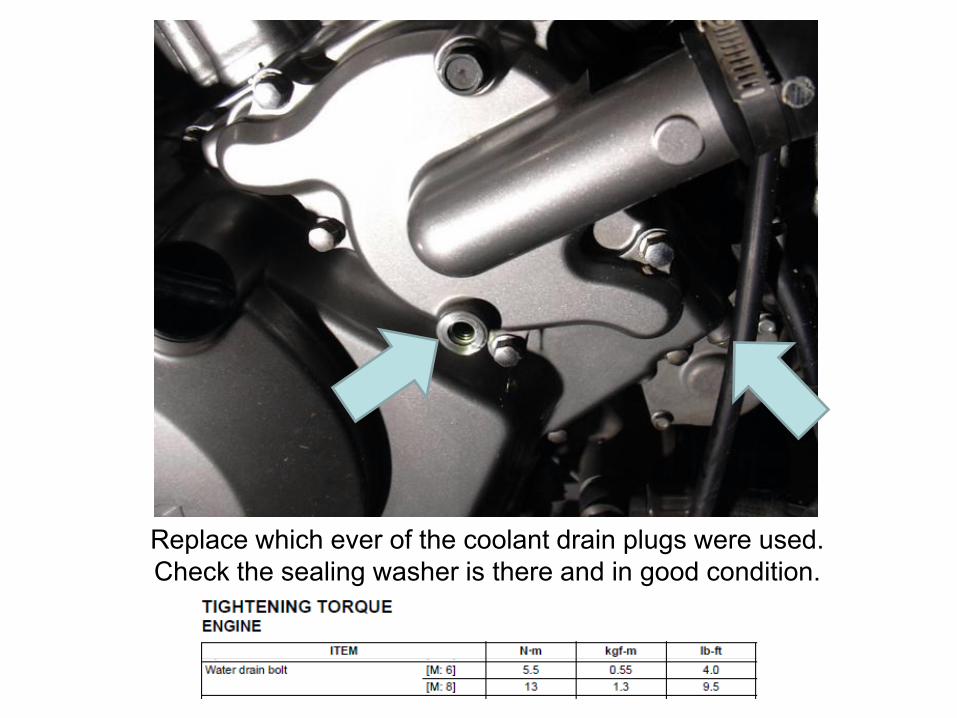
Replace which ever of the coolant drain plugs were used.
Check the sealing washer is there and in good condition.
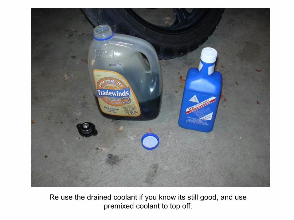
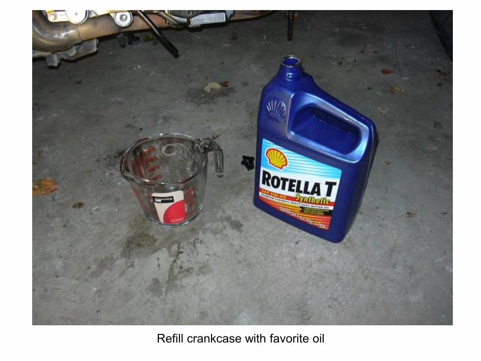
Re use the drained coolant if you know its still good, and use
premixed coolant to top off.
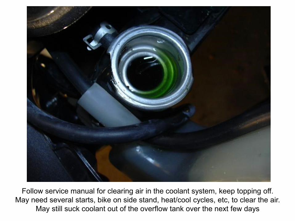
Follow service manual for clearing air in the coolant system, keep topping off.
May need several starts, bike on side stand, heat/cool cycles, etc, to clear the air.
May still suck coolant out of the overflow tank over the next few days
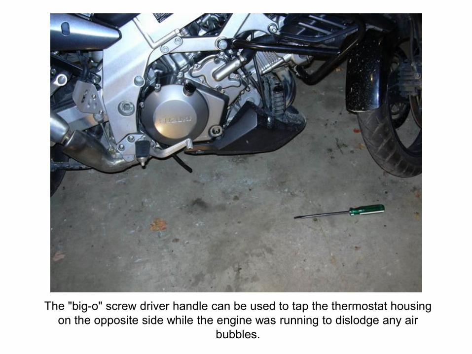
The "big-o" screw driver handle can be used to tap the thermostat housing
on the opposite side while the engine was running to dislodge any air
bubbles.
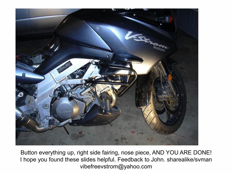
Button everything up, right side fairing, nose piece, AND YOU ARE DONE!
I hope you found these slides helpful. Feedback to John. sharealike/svman
Downloaded from