Embed Size (px)
Citation preview

N GPUR MUNICIP L CORPOR TION
PREPARATION OF MASTER PLAN / PERSPECTIVE
PLAN FOR DRAINAGE SYSTEM AND
REJUVENATION OF LAKES AND RIVERS OF
NAGPUR CITY FOR THE YEAR 2041
Shah Technical Consultants Pvt. Ltd.407, Raheja Centre, Nariman Point, Mumbai 40 0021, India
DRAFT DETAILED PROJECT REPORT OF
STORMWATER DRAINAGE SYSTEM
VOLUME - 1 NORTH ZONE
Dinesh Rathi & Associates6 Tatya Tope Nagar, West High Court Road, Nagpur – 440 015, India
With
FEBRUARY 2009
Submitted to:
EXECUTIVE ENGINEER (CONSTRUCTION)First Floor, Main Building
Nagpur Municipal Corporation
Mahanagarpalika Marg, Civil Lines
NAGPUR – 440001 (MS) INDIA
Draft Detailed Project Report Client: Nagpur Municipal Corporation
Project: Stormwater Drainage System
ST
Shah Technical Consultants Private Limited Page-1
With
Dinesh Rathi & Associates
EXECUTIVE SUMMARY
1.0 General
The report provides the Draft Detailed Project Report for the stormwater
drainage system for Nagpur Municipal Corporation. The consultancy work
for the master plan / perspective plan for stormwater drainage system for
Nagpur City for the year 2041 has been awarded by the Nagpur Municipal
Corporation to M/s Shah Technical Consultants (P) Ltd., Mumbai.
The Inception Report and the Master Plan Report for the consultancy work
was submitted to Nagpur Municipal Corporation. As part of the project
requirements a Draft Detailed Project Report (DPR) containing detailed
design, cost estimate and implementation for the stormwater drainage system
is now being submitted. The DPR is organized into the following Volumes-
Volume I : Main Report
Volume II : Hydraulic Statements of Stormwater Drainage System
Volume III : Drawings
Aim of Consultancy
The aim of the present consultancy assignment is to make readily available
document for the implementation of technically sound and viable schemes
forming integral parts of a comprehensive stormwater drainage system for
Nagpur City. The assignment includes preparation of Master Plan for a
stormwater drainage system, feasibility studies and preparation of Draft
Detailed Project Report for the master plan components, contract procurement
and provision of technical support during construction.
2.0 Existing Stormwater Drainage System
Nagpur City has an area of 217.56 sq.km. The present (Year 2007) population
is 25.49 Lakh. The projected population for the year 2041 is 62.75 Lakhs.
The annual rainfall is 1000 mm.
Existing stormwater drainage system in Nagpur City covers 3 major storm
water carrying streams i.e. the Pioli river, Nag river and Pora river which falls
outside NMC boundary.
The Pioli river starts from the gate of Gorewada tank at the northwest end of
the city runs through the north to the eastern end of the city. Final disposal of
stormwater from part of west Nagpur and north Nagpur is into this river
through minor and major nallahs.

Draft Detailed Project Report Client: Nagpur Municipal Corporation
Project: Stormwater Drainage System
ST
Shah Technical Consultants Private Limited Page-2
With
Dinesh Rathi & Associates
The Nag river starts from Ambazari lake’s overflow weir at the western end ofthe city and runs through the middle of the city towards the east. The final
disposal of stormwater from part of west Nagpur, south Nagpur, central
Nagpur and east Nagpur is into this river through minor and major nallahs.
Pora river starts from Sonegaon area. Stormwater from southern part of Nagpur city drains to this river through minor and major nallahs.
At present, 40% area inside the ring road is covered with stormwater drainagenetwork.
Observations on existing stormwater drainage (SWD) network and need forcomprehensive stormwater drainage system:
• Almost all stormwater drains get flooded during monsoon
• In many places, final disposal of sewage is in the stormwater drain and
stormwater drainage gets flooded
• Nallahs, rivers, drains and chambers are heavily silted and need cleaning
• Many places, sewers discharge directly into the rivers and major nallahs,due to which the ground water and surface water is getting polluted
To overcome the above situation the sewerage and stormwater disposal system
should be implemented, failing which problems will be posed to the
environment of the city affecting public health and the commercial activities.The pollution loads to Pioli river and Nag river and other natural nallahs
should be intercepted and should be conveyed to sewage treatment plant to
improve the hygienic conditions.
To sustain the high rate of growth in the city, the infrastructure in general has
to keep up and the stormwater drainage system is one of the importantcomponents of the infrastructure that needs to be developed on priority. To
avoid flooding in the project area proper stormwater drainage system is
necessary.
Local ponds in low lying area - The adverse topography and manmade hurdles
obstruct the free disposal of the normal stormwater within the city. Ponds leadto unhygienic conditions in the surroundings. Improper inlets to the existing
stormwater drains cause pool of water at few locations. To rectify the
situation proper measures are necessary.
River and nallahs – The flood protection measures are necessary on the banks
of Nag and Pioli rivers and nallahs at various locations.

Draft Detailed Project Report Client: Nagpur Municipal Corporation
Project: Stormwater Drainage System
ST
Shah Technical Consultants Private Limited Page-3
With
Dinesh Rathi & Associates
3.0 Data Collection, Topographical Survey
As a part of planning and location studies, collection of all available
information pertaining to the project is vital for bringing out a proper design of
the project and for its successful completion. Basic data required for
formulation of the project such as project area map, Nagpur city development
plan showing existing and proposed landuse, existing drainage system details,
rainfall data from year 1969-2000, physical characteristics of drainage basin,
flood data etc. information have been collected and analysed.
Topographical Survey Contour Map, Soil Investigations
A topographic survey has been carried out for the un-sewered area of the city.
Total length of road survey carried out is 800 Kms and a contour map has
been prepared for the NMC area taking into account the new street levels as
well as street levels available for the areas sewered. All new roads have been
incorporated into the city map.
Survey of nallahs and river basins have been carried out. L-Sections and
Cross-Sections have been prepared. Total surveyed length of nallahs in the
north zone is 76 kms and total surveyed length of Pioli river, Nag river and
Pora river is 47.9 kms. Soil investigation has been carried out. Generally the
ground water levels ranged from 0.2 m to 9.12 m in the area.
4.0 Hydrologic Analysis of Drainage Facility Design
The rational method is adopted for the conversion of precipitation into runoff.
The following equation is used for the calculation of peak runoff.
Q = 10 CiA ………… Equation (1)
where
Q = peak runoff in m3/hr
i = rainfall intensity in mm/hr
C = runoff coefficient
A = the catchment area in ha

Draft Detailed Project Report Client: Nagpur Municipal Corporation
Project: Stormwater Drainage System
ST
Shah Technical Consultants Private Limited Page-4
With
Dinesh Rathi & Associates
4.1 Frequency of Storm
As mentioned in CPHEEO manual storm frequency is adopted depending on
the importance of the area to be drained.
a) Residential
i) Peripheral area twice a year
ii) Central and comparatively high priced area once a year
b) Commercial and high priced area once in two years
For nallahs the storm frequency considered is once in 2 years and for river
channel once in 25 years.
4.2 Storm Duration
Storm duration is selected on the basis the time of concentration of the
drainage basin. As per CPHEEO manual, the time of concentration (tc) is
calculated as sum of (i) Inlet time (ti) & (ii) time of flow in storm drain to the
outlet (tf).
Time of inlet is worked out using Kirpich equation. Time of inlet adopted is-
River - 60 Min.
Nallah - 22 to 75 Min
Road side drain - 30 Min
4.3 Rainfall Intensity
The available data acquired from Pune Meteorological Department includes
24 hr. rainfall data from year 1969-2000 for the Nagpur City. These data sets
are used to carryout frequency analysis to determine the magnitude of peak
flows of known return period to achieve an optimized design.
The intensities for different return periods and durations are formulated using
IDF curves using empirical equations and theories of probability.
Adopted intensity of storm for various return period and duration is provided
in the tabular form.
Table No.I shows Intensity of Storm for Various Return Period and Duration
Gumbels Extreme Value (type I) distribution

Draft Detailed Project Report Client: Nagpur Municipal Corporation
Project: Stormwater Drainage System
ST
Shah Technical Consultants Private Limited Page-5
With
Dinesh Rathi & Associates
Table No.I: Intensity of Storm for Various Return Period and Duration
Gumbels Extreme Value (type I) distribution
Rainfall Intensity, mm/hr
Return Period , YearsTime in
minutes 0.50 1.00 2.00 5.00 10.00 25.00 100.00
5.00 158.46 181.83 208.65 250.28 287.19 344.48 453.60
10.00 99.59 114.28 131.14 157.30 180.50 216.51 285.09
15.00 75.90 87.10 99.94 119.88 137.56 165.00 217.27
20.00 62.59 71.83 82.42 98.86 113.45 136.08 179.18
25.00 53.90 61.85 70.98 85.14 97.69 117.18 154.30
30.00 47.70 54.74 62.82 75.35 86.46 103.71 136.56
35.00 43.02 49.37 56.65 67.95 77.98 93.53 123.16
40.00 39.34 45.14 51.80 62.14 71.30 85.53 112.62
45.00 36.36 41.72 47.87 57.42 65.89 79.04 104.07
50.00 33.88 38.88 44.61 53.51 61.40 73.65 96.98
55.00 31.78 36.47 41.85 50.20 57.60 69.09 90.98
60.00 29.98 34.41 39.48 47.36 54.34 65.18 85.83
70.00 27.04 31.03 35.61 42.71 49.01 58.78 77.40
80.00 24.73 28.37 32.56 39.05 44.81 53.75 70.78
90.00 22.85 26.22 30.09 36.09 41.41 49.67 65.41
100.00 21.29 24.43 28.04 33.63 38.59 46.29 60.95
110.00 19.98 22.92 26.30 31.55 36.20 43.43 57.18
120.00 18.84 21.62 24.81 29.76 34.15 40.97 53.94
IDF CURVES
0.00
25.00
50.00
75.00
100.00
125.00
150.00
175.00
200.00
225.00
250.00
275.00
300.00
0 15 30 45 60 75 90 105 120 135 150
Duration in Minutes
I n t e n s i t y i n m m /
0.5 Year
1 Year
2 Year
5 Year
25 Year
100 Year
`
Figure I: Intensity- Frequency-Duration Curves by Gumbel’s Extreme
Value (type 1) distribution

Draft Detailed Project Report Client: Nagpur Municipal Corporation
Project: Stormwater Drainage System
ST
Shah Technical Consultants Private Limited Page-6
With
Dinesh Rathi & Associates
4.4 Coefficient of Runoff (C)
The co-efficient of runoff (C) is the portion of precipitation that makes its way
to the drain. Co-efficient of runoff for various surfaces has been adopted from
the Handbook and composite ‘C’ value have been calculated for different land
uses contributing to a single catchments.
4.5 Catchment Area
Based on topography, catchment areas contributing to proposed drain is
calculated in hectares.
4.6 Calculation of Peak Runoff (Stormwater Flow)
From the rainfall intensity (I) catchments area (A) and composite value of ‘C’
peak flow (Q) in the drain have been calculated using Equation-1.
5.0 Concept, Methodologies and Procedures
Using detailed base map of the project area the project area shall be divided
into catchments and sub-catchments based on topography.
Surface runoff from property and roads will discharge to minor or major
nallahs through road side drains and further disposal will be mainly throughmajor nallahs to river.
i) Hydrologic and hydraulic analysis shall be carried out for nallahs and
river sections.
ii) For preliminary design the single section method shall be used and for
detailed engineering the step backwater method shall be used for
nallah sections.
iii) Hydraulic analysis for nallah section be carried out for two alternatives
as follows:
• Alternative 1 – Concrete lining for side walls and bottom without
treatment i.e. natural channel
• Alternative 2 – Concrete lining for side walls as well as bottom of
nallah
iv) For river channelisation hydraulic analysis shall be carried out for
concrete lining on side walls and bottom without treatment.
STORMCAD latest version software shall be used for design.

Draft Detailed Project Report Client: Nagpur Municipal Corporation
Project: Stormwater Drainage System
ST
Shah Technical Consultants Private Limited Page-7
With
Dinesh Rathi & Associates
STORMCAD-V8XM edition and StormCAD Version 4.1 Software
shall be used for design of stormwater drainage system.
v) Rectangular sections shall be proposed for river channel sections and
trapezoidal sections for nallah channel section.
vi) R.C.C. structures shall be proposed for nallah and river section.
vii) Road side drains shall be proposed on both side of roads except in
some part of slum area.
viii) Drains shall be planned taking into consideration the ground levels,
slope of the ground, valley and ridges and also the land use planned.
ix) Drains shall be planned to get good longitudinal slope, considering the
nature of soil and subsoil water level. Large areas shall be subdivided
into small grids to avoid a long main drain.
x) Efficiency in maintenance of drainage system shall be given an
important consideration in selecting the size, shape and the location.
xi) An attempt shall be made in the design to provide higher starting and
higher outfall bed levels in drains. A free outfall shall be attempted as
far as possible.
xii) Design of main drain shall be so made as to allow use of the normal
methods for desilting operations.
xiii) Existing drain system shall be checked for its adequacy and
replacement shall be proposed for the drains which are not adequate in
capacity.
6.0 Design Criteria
i) The design criteria adopted for the project proposals are based on:
a) Manual on sewerage and sewage treatment by CPHEEO
b) Stormwater collection system design handbook by Larry W
Mays
c) ICR-SP-50- Guidelines on Urban Drainage, New Delhi 1999
ii) Capacity of drains shall be designed by using manning’s formula:
2/3 1/ 21 Q AR S
n= ………… Equation (2)

Draft Detailed Project Report Client: Nagpur Municipal Corporation
Project: Stormwater Drainage System
ST
Shah Technical Consultants Private Limited Page-8
With
Dinesh Rathi & Associates
Whereas
Q = discharge in cum/sec
n = manning’s coefficient of roughness
R = hydraulic radius in m
S = Channel Slopes
A = area of cross section in m2
Manning’s co-efficient of roughness for various types of surfaces
Type of surface Value of ‘n’
Concrete pipe - 0.013
Natural stream / Nallah - 0.022
iii) Type of drain
a) Closed Conduit
The pipe size of conduit shall be determined using peak
discharge for each proposed pipe and the manning’s formula
assuming full pipe flow condition. All conduits are proposed to
be designed to flow 0.8 full at peak flow.
b) Minimum Conduit Size
Minimum diameter of the pipe shall be 300 mm.
c) Open Channel
The rectangular and trapezoidal sections are easy to construct
and are considered most suitable.
d) Economical Sections
As far as possible for obtaining economical sections for lined
drains the bed width and depth shall be proposed as follows.
Rectangular drain
b = 2d
Trapezoidal drain

Draft Detailed Project Report Client: Nagpur Municipal Corporation
Project: Stormwater Drainage System
ST
Shah Technical Consultants Private Limited Page-9
With
Dinesh Rathi & Associates
b = 0.8 2d (1:1 side slope)
b = 1.24 d (½:1 side slope)
e) Minimum section of drain
It is recommended that minimum width of a drain should not be
less than 300 mm.
iv) Minimum and Maximum Velocities
Type of Drain Minimum Velocity
(m/sec)
Maximum Velocity
(m/sec)
Pipe drain 0.8 3.0
Internal drain (R.C.C.) 0.45 3.0
Min drain (R.C.C.) 0.75 3.0
Maximum spacing of inlet would depend upon various conditions of
road, size and type of inlet and rainfall.
Stormwater inlets – A maximum spacing of 30 m shall be provided.
Location of inlet for channel
Rectangular Type drain -Both side of road below footpath
For each inlet covered inlet chamber shall be provided for maintenance
purpose.
7.0 Proposed Stormwater Drainage System
7.1 The primary goal of storm drain design is to minimize water logging and limit
the amount of water flowing on the travel way or ponding at sag points in the
roadway grade to quantities that will not interfere with the passage of traffic
for the design frequency storm.
7.2 Drainage Basin in Project Area
Project area is divided in three river valleys. 1st in north zone i.e. Pioli river
basin, 2nd
in central zone i.e. Nag river basin and 3rd
in south zone i.e. Pora
river basin.

Draft Detailed Project Report Client: Nagpur Municipal Corporation
Project: Stormwater Drainage System
ST
Shah Technical Consultants Private Limited Page-10
With
Dinesh Rathi & Associates
7.3 Pioli River Basin
Pioli river basin (North Zone) consists of roadside drain, minor and major
nallahs. There are 25 minor nallahs and 14 major nallahs.
Component 1: (Roadside Drains) includes Hydrologic and Hydraulic
Analyse of Existing and Proposed Roadside Drain
7.4 Roadside Drains – Sizing of Drains
i) Rational method is used for determination of discharge in each reach.
ii) The manning’s formula is used for determination of capacity of drains.
iii) STORMCAD-V8XM edition and STORMCAD version 4.1 Software
have been used for the design of stormwater drainage system.
Table II provides proposed size drain, total length and type of drain in each
nallah basin in the north zone and Table III provides proposed drain size , total
length and type of drain in cluster.
Table II: Proposed drain size, Total Length and Type of drain in nallah
basin
S. No. Section Size Length (m) Type
Shanthi Nagar Nallah Basin
1 300x150 42289
2 300x200 11000
3 400x200 7107
4 400x250 9538
5 400x300 281
6 500x250 5987
7 500x300 8107
8 600x300 3276
9 600x350 4328
10 600x400 313
11 700x300 1167
12 700x350 1462
13 700x400 4530
14 800x400 314
15 800x450 1444
16 900x400 12
17 900x450 1421
18 900x500 1198
19 900x550 104
20 1000x500 239
21 1000x550 38
22 1100x550 633
Rectangular Channel with
cover

Draft Detailed Project Report Client: Nagpur Municipal Corporation
Project: Stormwater Drainage System
ST
Shah Technical Consultants Private Limited Page-11
With
Dinesh Rathi & Associates
S. No. Section Size Length (m) Type
23 1100x600 497
24 1100x650 433
25 1200x600 215
26 1200x650 144
27 1300x650 128
28 1300x700 78
29 1400x700 936
30 1400x750 7
31 1500x750 121
32 1500x800 60
33 1600x800 148
34 1600x850 560
35 1700x900 158
36 1800x900 87
Chamar Nallah Basin
37 300x150 154575
38 300x200 49837
39 400x200 28066
40 400x250 28126
41 400x300 742
42 500x250 13605
43 500x300 18460
44 600x300 8014
45 600x350 8163
46 600x400 353
47 700x300 1724
48 700x350 3896
49 700x400 11735
50 700x450 216
51 800x400 3130
52 800x450 3402
53 800x500 150
54 900x450 1647
55 900x500 3079
56 900x550 471
57 1000x500 709
58 1000x550 1766
59 1000X900 68
60 1100x550 621
61 1100x600 1266
62 1100x650 431
63 1200x600 326
64 1200x650 837
65 1300x650 145
66 1300x700 1606
67 1400x700 79
68 1400x750 168
69 1500x800 1881
Rectangular Channel with
cover

Draft Detailed Project Report Client: Nagpur Municipal Corporation
Project: Stormwater Drainage System
ST
Shah Technical Consultants Private Limited Page-12
With
Dinesh Rathi & Associates
S. No. Section Size Length (m) Type
Bor Nallah Basin
70 300x150 26696
71 300x200 6567
72 400x200 2287
73 400x250 8598
74 400x300 382
75 500x250 1022
76 500x300 3874
77 600x300 1034
78 600x350 460
79 600x400 103
80 700x300 12
81 700x350 629
82 700x400 717
83 800x400 445
84 800x450 731
85 800x500 55
86 900x500 55
87 1000x550 213
88 1000x600 102
89 1100x550 12
90 1100x600 102
91 1200x600 74
Rectangular Channel with
cover
Pioli River Basin
92 300x150 55893
93 300x200 14984
94 400x200 14087
95 400x250 7430
96 400x300 4540
97 500x250 4253
98 500x300 6943
99 600x300 4368
100 600x350 1218
101 600X400 30
102 700x300 2520
103 700x350 2300
104 700x400 2855
105 700x450 760
106 800x300 47
107 800x400 3214
108 800x450 3768
109 800x500 365
110 900x450 1121
111 900x500 2261
112 900x550 848
113 1000x500 410
114 1000x550 468
115 1000x600 271
Rectangular Channel with
cover

Draft Detailed Project Report Client: Nagpur Municipal Corporation
Project: Stormwater Drainage System
ST
Shah Technical Consultants Private Limited Page-13
With
Dinesh Rathi & Associates
S. No. Section Size Length (m) Type
116 1100x550 219
117 1100x600 59
118 1200x600 528
119 1200x650 841
120 1200x700 9
121 1400x700 320
122 1400x800 1178
123 1600x800 282
124 1800x900 617
* Total Length includes drains on both side of road
Table III: Proposed Drain Size, Total Length and Type of Drain
(Cluster)Section Size (m) Length (m) Section Size (m) Length (m)
300x150 349220 900x500 12531
300x200 123978 900x550 35
350x200 183 900x600 6095
400x200 78274 900x700 56
400x250 76294 1000x500 2298
400x300 43 1000x550 6685
500x250 34268 1000x600 36
500x300 45484 1000x700 278
500x900 7 1000x800 102
600x300 16052 1100x550 2168
600x350 16082 1100x600 5788
660x750 5920 1100x650 1537
600x400 1700 1200x600 1873
700x300 2722 1200x650 2855
700x350 6801 1300x650 1427
700x400 38289 1300x700 5082
700x450 0 1400x700 2013
750x450 163 1400x750 1337
800x300 0 1400x800 298
800x400 7497 1500x750 1207
800x450 16350 1500x800 4167
850x700 106 1600x800 2039
800x500 0 1700x850 10
900x400 0 1800x900 0
900x450 8251
7.5 Roadside Drains in Slum Area
In slum area roadside drains are proposed on both side of road on broader
roads. Storm from narrow roads will be directly picked upto these drains.

Draft Detailed Project Report Client: Nagpur Municipal Corporation
Project: Stormwater Drainage System
ST
Shah Technical Consultants Private Limited Page-14
With
Dinesh Rathi & Associates
7.6 Existing Drainage System Hydraulic Analysis
Adequacy of existing drain size have been checked using STORMCAD
Software for inadequate drains replacement is proposed.
Component 2: (Major Drainage Channels) includes Hydrologic and
Hydraulic Analysis of Major Drainage Channels i.e. Major & Minor
Nallahs
7.7 Hydrologic and Hydraulic Analysis have been carried out for each nallah and
river. Hydrologic analysis refer to the development of water flows off of the
land surface. Hydrologic analysis determines how much and how fast water
runoff, of the land into the system’s hydraulic elements such as nallahs,
culverts and the river. Hydraulic analysis determines the sections for the
calculated hydraulic flow.
Table IV provides proposed Nallah/Channel section, length, type and slope of
each nallah.
7.8 Catchment area and time of inlet intensity rainfall of 1st reach of each nallah
basin in North zone area (2 years return period) is provided in Table V.
7.9 Hydraulic analysis have been carried out for each nallah and river considering
concrete lined walls and natural bottom and using STORMCAD Software.
Trapezoidal sections have been proposed nallah for channalisation and
rectangular section for river channalisation.
Table IV: Proposed Nallah/Channel Section, Length , Type and Slope of each Nallah
ChainageSection Size Proposed
(m)S.
No. Name of Nallah
From ToTop
WidthBottomWidth
WaterDepth
SectionType
Slope(m/km)
Coeffecientof Runoff,Composite
C
Coeffiecientof
Roughness,Composite
n
1 L1 2702 1890 15.0 14.0 0.8 Trapezoidal 4.18 0.55 - 0.57 0.021
1890 1170 19.0 17.8 0.9 " 4.34 0.021
1170 0 22.0 20.7 0.9 " 3.66 0.021
2L2 (Ved Nagar)
3210 2130 6.0 5.1 0.7 " 4.98 0.41 - 0.53 0.021
2130 1080 7.0 6.0 0.8 " 3.85 0.021

Draft Detailed Project Report Client: Nagpur Municipal Corporation
Project: Stormwater Drainage System
ST
Shah Technical Consultants Private Limited Page-15
With
Dinesh Rathi & Associates
ChainageSection Size Proposed
(m)S.
No. Name of Nallah
From ToTop
Width
Bottom
Width
Water
Depth
SectionType
Slope(m/km)
Coeffecient
of Runoff,
Composite
C
Coeffiecientof
Roughness,
Compositen
1080 838 10.0 8.7 0.8 Trapezoidal 2.94 0.021
838 0 10.0 8.7 0.9 " 3.15 0.021
2.1 L2R1 2580 1710 8.1 7.3 0.6 " 9.01 0.40 - 0.53 0.021
1710 900 9.0 8.2 0.7 " 4.67 0.021
900 0 9.0 8.2 0.6 " 3.48 0.021
3 L3 (Nara) 3545 3000 12.0 11.0 0.8 " 2.42 0.36 - 0.51 0.021
3000 2178 12.0 11.0 0.9 " 2.45 0.021
2178 1286 13.0 12.0 0.9 " 2.52 0.021
1286 810 15.0 13.9 0.9 " 3.63 0.021
810 0 15.0 13.9 0.8 " 3.62 0.021
3.1 L3L1 1445 750 5.0 4.1 0.7 " 10.00 0.53 - 0.55 0.021
750 0 8.0 7.0 0.7 " 7.97 0.021
3.2 L3L2 720 0 6.2 5.2 0.9 " 2.34 0.6 0.021
4 L4 10160 8730 10.2 9.1 0.9 " 3.18 0.50 - 0.55 0.021
8730 6390 12.0 10.8 1.1 " 2.36 0.021
6390 3600 12.1 10.7 1.2 " 1.96 0.021
3600 1070 16.0 14.4 1.4 " 1.61 0.021

Draft Detailed Project Report Client: Nagpur Municipal Corporation
Project: Stormwater Drainage System
ST
Shah Technical Consultants Private Limited Page-16
With
Dinesh Rathi & Associates
ChainageSection Size Proposed
(m)S.
No.
Name of
Nallah
From ToTop
Width
Bottom
Width
Water
Depth
Section
Type
Slope
(m/km)
Coeffecient
of Runoff,
Composite
C
Coeffiecient
of
Roughness,
Composite
n
1070 0 16.0 14.4 1.2 Trapezoidal 1.18 0.021
4.1 L4R1 1465 690 7.0 6.4 0.5 " 4.70 0.52 - 0.6 0.021
690 0 8.0 7.4 0.5 " 3.83 0.021
5 R1 500 0 6.0 5.1 0.6 " 253.00 0.509 0.021
6 R2 (Bor) 6225 5883 6.0 5.4 0.5 " 30.57 0.50 - 0.56 0.021
5883 5721 6.1 5.4 0.5 " 17.78 0.021
5721 5439 6.1 5.4 0.6 " 13.48 0.021
5439 5400 6.3 5.4 0.7 " 10.00 0.021
5400 4514 12.0 11.1 0.9 " 8.70 0.021
4514 4410 12.1 11.1 0.9 " 6.67 0.021
4410 4133 14.0 13.0 1.0 " 5.56 0.021
4133 3600 14.0 13.0 1.0 " 5.18 0.021
3600 3564 18.0 16.8 1.0 " 5.00 0.021
3564 2827 18.0 16.8 1.1 " 4.80 0.021
2827 2340 18.0 16.8 1.1 " 4.01 0.021
2340 2110 18.1 16.8 1.2 " 4.00 0.021
2110 1980 18.1 16.8 1.2 " 4.00 0.021

Draft Detailed Project Report Client: Nagpur Municipal Corporation
Project: Stormwater Drainage System
ST
Shah Technical Consultants Private Limited Page-17
With
Dinesh Rathi & Associates
ChainageSection Size Proposed
(m)S.
No. Name of Nallah
From ToTop
Width
Bottom
Width
Water
Depth
SectionType
Slope(m/km)
Coeffecient
of Runoff,
Composite
C
Coeffiecientof
Roughness,
Compositen
1980 1752 22.2 20.7 1.3 Trapezoidal 3.33 0.021
1752 810 22.2 20.7 1.4 " 3.33 0.021
810 715 25.0 23.5 1.4 " 2.51 0.021
715 0 25.0 23.5 1.2 " 2.18 0.021
6.1 R2 L1 1520 1000 3.2 2.5 0.4 " 16.17 0.40 - 0.66 0.021
1000 450 4.7 3.9 0.6 " 9.31 0.021
450 0 5.1 4.3 0.7 " 7.98 0.021
6.2 R2 L2 1580 1260 3.3 2.5 0.6 " 60.60 0.54 - 0.61 0.021
1260 540 5.2 4.3 0.7 " 14.51 0.021
540 0 6.6 5.6 0.9 " 6.13 0.021
6.3 R2 L3 1890 1260 5.1 4.4 0.6 " 23.67 0.55 - 0.62 0.021
1260 630 6.1 5.3 0.7 " 8.65 0.021
630 0 7.2 6.2 0.7 " 5.41 0.021
6.4 R2 L4 980 630 3.2 2.6 0.4 " 56.66 0.57 - 0.61 0.021
630 240 4.1 3.5 0.5 " 19.24 0.021
240 0 6.0 5.4 0.6 " 11.05 0.021
6.5 R2 L5 450 0 4.1 3.5 0.3 " 48.33 0.65 0.021

Draft Detailed Project Report Client: Nagpur Municipal Corporation
Project: Stormwater Drainage System
ST
Shah Technical Consultants Private Limited Page-18
With
Dinesh Rathi & Associates
ChainageSection Size Proposed
(m)S.
No.
Name of
Nallah
From ToTop
Width
Bottom
Width
Water
Depth
Section
Type
Slope
(m/km)
Coeffecient
of Runoff,
Composite
C
Coeffiecient
of
Roughness,
Composite
n
6.6 R2 R1 1050 540 4.1 3.4 0.4 Trapezoidal 23.08 0.48 - 0.51 0.021
540 0 6.1 5.3 0.7 " 6.45 0.021
6.7 R2 R2 580 0 5.1 4.5 0.3 " 23.77 0.65 0.021
7 R3 (Chamar) 5610 5546 8.0 0.8 Rectangular 3.33 0.52 - 0.62 0.021
5546 5481 8.0 0.8 " 3.34 0.021
5481 5420 11.0 0.6 " 2.23 0.021
5420 5318 11.0 0.6 " 3.33 0.021
5318 5115 11.0 0.6 " 3.33 0.021
5115 4717 13.0 0.8 " 2.92 0.021
4717 4325 13.0 0.8 " 2.77 0.021
4325 3960 13.0 1.2 " 1.67 0.021
3960 3600 14.0 1.2 " 1.5 0.021
3600 3193 14.0 1.2 " 1.31 0.021
3193 2700 16.0 1.3 " 1.33 0.021
2700 2280 20.0 1.2 " 1.18 0.021
2280 1770 20.0 1.3 " 1.2 0.021
1770 1350 22.0 1.4 " 1.02 0.021

Draft Detailed Project Report Client: Nagpur Municipal Corporation
Project: Stormwater Drainage System
ST
Shah Technical Consultants Private Limited Page-19
With
Dinesh Rathi & Associates
ChainageSection Size Proposed
(m)S.
No.
Name of
Nallah
From ToTop
Width
Bottom
Width
Water
Depth
Section
Type
Slope
(m/km)
Coeffecient
of Runoff,
Composite
C
Coeffiecient
of
Roughness,
Composite
n
1350 780 22.0 1.4 Rectangular 1.1 0.021
780 360 26.0 1.6 " 1.05 0.021
360 0 26.0 1.4 " 1.05 0.021
7.1 R3 L1 1440 1037 6.0 0.8 " 9.33 0.61 - 0.62 0.021
1037 720 6.0 0.8 " 9.72 0.021
720 439 10.0 0.9 " 5.00 0.021
439 0 10.0 0.8 " 6.13 0.021
7.2 R3 L2 810 390 4.5 0.7 " 4.47 0.64 0.021
390 0 4.5 0.7 " 4.51 0.021
7.3 R3 R1 4375 4140 8.0 0.9 " 2.84 0.55 - 0.59 0.021
4140 3890 8.0 0.9 " 2.67 0.021
3890 3600 8.0 0.8 " 2.99 0.021
3600 2880 8.0 0.8 " 2.36 0.021
2880 2100 10.0 1.4 " 1.43 0.021
2100 1440 10.0 1.3 " 1.52 0.021
1440 710 11.0 1.4 " 1.31 0.021
710 0 11.0 1.3 " 1.45 0.021

Draft Detailed Project Report Client: Nagpur Municipal Corporation
Project: Stormwater Drainage System
ST
Shah Technical Consultants Private Limited Page-20
With
Dinesh Rathi & Associates
ChainageSection Size Proposed
(m)S.
No.
Name of
Nallah
From ToTop
Width
Bottom
Width
Water
Depth
Section
Type
Slope
(m/km)
Coeffecient
of Runoff,
Composite
C
Coeffiecient
of
Roughness,
Composite
n
7.4 R3 R2 1775 1380 6.5 0.8 Rectangular 12.12 0.51 - 0.52 0.021
1380 900 7.0 0.8 " 10.00 0.021
900 360 9.0 0.8 " 8.78 0.021
360 0 9.0 0.8 " 6.06 0.021
7.5 R3 R3 1430 870 3.0 0.5 " 8.03 0.54 - 0.61 0.021
870 450 5.5 0.7 " 4.29 0.021
450 0 7.0 0.8 " 3.33 0.021
7.6 R3 R4 330 0 3.0 0.3 " 7.22 0.65 0.021
8 R4 3080 2070 8.0 7 0.8 Trapezoidal 11.76 0.52 - 0.63 0.021
2070 990 10.0 8.8 0.9 " 6.41 0.021
990 0 11.0 9.7 0.9 " 5.65 0.021
9 R5 180 0 5.6 4.8 0.5 " 17.04 0.65 0.021
10 R6 710 0 3.0 2.4 0.4 " 11.33 0.604 0.021
11 R7 2270 1484 3.0 2.2 0.6 " 12.60 0.60 - 0.63 0.021
1484 720 3.5 2.6 0.6 " 7.62 0.021
720 0 4.0 3.1 0.6 " 6.49 0.021
12 R8 570 0 4.0 3.4 0.4 " 8.97 0.65 0.021

Draft Detailed Project Report Client: Nagpur Municipal Corporation
Project: Stormwater Drainage System
ST
Shah Technical Consultants Private Limited Page-21
With
Dinesh Rathi & Associates
ChainageSection Size Proposed
(m)S.
No.
Name of
Nallah
From ToTop
Width
Bottom
Width
Water
Depth
Section
Type
Slope
(m/km)
Coeffecient
of Runoff,
Composite
C
Coeffiecient
of
Roughness,
Composite
n
13 R9 1830 930 12.1 11.2 0.5 Trapezoidal 2.52 0.58 - 0.60 0.021
930 0 14.0 12.9 0.6 " 1.13 0.021
14R10
(Shantinagar)7110 6385 8.0 0.7 Rectangular 3.81 0.54 - 0.61 0.021
6385 6274 8.0 0.7 " 2.86 0.021
6274 5670 8.0 0.7 " 2.86 0.021
5670 5333 11.0 1.0 " 2.20 0.021
5333 5250 13.0 1.0 " 1.93 0.021
5250 4742 13.0 1.0 " 2.00 0.021
4742 4590 13.0 1.0 " 2.00 0.021
4590 4060 16.5 1.2 " 1.65 0.021
4060 3210 16.5 1.1 " 1.69 0.021
3210 2255 17.5 1.4 " 1.66 0.021
2255 0 17.5 1.4 " 1.00 0.021
14.1 R10 L1 230 0 2.0 0.4 " 4.60 0.65 0.021
14.2 R10 L2 580 0 1.8 0.5 " 5.22 0.65 0.021
14.3 R10 L3 1190 0 11.0 0.4 " 5.37 0.65 0.021
14.4 R10 L4 230 0 2.1 0.4 " 3.53 0.65 0.021

Draft Detailed Project Report Client: Nagpur Municipal Corporation
Project: Stormwater Drainage System
ST
Shah Technical Consultants Private Limited Page-22
With
Dinesh Rathi & Associates
ChainageSection Size Proposed
(m)S.
No. Name of Nallah
From ToTop
Width
Bottom
Width
Water
Depth
SectionType
Slope(m/km)
Coeffecientof Runoff,Composite
C
Coeffiecient
ofRoughness,
Compositen
14.5 R10 R1 380 0 2.5 0.4 Rectangular 6.95 0.65 0.021
14.6 R10 R2 50 0 2.0 0.2 " 6.60 0.65 0.021

Draft Detailed Project Report Client: Nagpur Municipal Corporation
Project: Stormwater Drainage System
ST
Shah Technical Consultants Private Limited Page-23
With
Dinesh Rathi & Associates
Table V: Catchment Area and Time of Concentration of Nallah Basins (2 yrs Return Period)
S.
No. Name of Nallah
Catchment
Area (ha)
Highest G.L
(m)
Lowest G.L
(m)
Longest
Length
(m)
Slope
Time of
Concentration
Tc (min)
Intensity
(mm/hr)
1 L1 973.38 320.00 308.97 2237 0.0049 57.13 40.80
3 L2 (Ved Nagar Nallah) 375.12 308.00 294.56 1060 0.0127 22.34 76.52
4 L3 (Nara Nallah) 754.96 312.00 303.26 1950 0.0045 53.31 42.74
6 L4 1105.11 302.50 297.80 800 0.0059 24.19 72.56
7 R1 98.30 310.00 307.30 640 0.0042 23.14 74.74
2 R2 (Bor Nallah) 1362.21 367.50 341.33 1460 0.0179 25.02 70.94
5 R3 (Chamar Nallah) 1737.20 322.50 300.45 1270 0.0174 22.75 75.60
8 R4 317.49 326.50 318.25 950 0.0087 23.76 73.44
9 R5 59.23 301.50 296.80 750 0.0063 22.45 76.27
10 R6 21.88 303.00 301.20 545 0.0033 22.47 76.23
11 R7 (Taj Nagar Nallah) 59.70 314.50 311.70 645 0.0043 23.03 74.99
12 R8 (Vishwas Nagar Nallah) 27.13 299.50 297.60 555 0.0034 22.48 76.22
13 R9 137.33 287.50 285.40 640 0.0033 25.49 70.05
14 R10 (Shantinagar Nallah) 794.59 307.00 299.70 950 0.0077 24.90 71.16

Draft Detailed Project Report Client: Nagpur Municipal Corporation
Project: Stormwater Drainage System
ST
Shah Technical Consultants Private Limited Page-24
With
Dinesh Rathi & Associates
Component 3: (Disposal) includes Hydrologic and Hydraulic Analysis of
River
7.10 Pioli river return period is proposed as 25 years and with 60 minute duration.
(Time of inlet) rainfall intensity is 65 mm/hr from IDF curves.
Catchment area and peak flow in various reaches of Pioli river segment is
provided in Table VI below.
Table VI: Catchment area and peak flow in various reaches of Pioli river
segment
From To
1 0 470 205 73.24
2 470 2062 205 73.24
3 2062 2342 585 98.82
4 2342 4322 1344 221.21
5 4322 6355 533 233.16
6 6355 6953 793 266.24
7 6953 8330 933 308.60
8 8330 12225 451 319.26
9 12225 14863 1695 380.37
10 14863 17635 1850 416.06
11 17635 17815 849 424.12
Details of Pioli River Basin
ChainageSr No
Catchment
Area (ha)
Peak Flow
(m3 /s)
Table VII below provides proposed hydraulic sections of Pioli river for a flood
frequency of 25 years.
Table VII: Hydraulic Sections of Pioli River for a flood Frequency of 25
Years
WidthChainage Depth
25 Years
0 - 470 River front development
470 - 2062 1.50 45.0
2062 - 2342 2.00 45.0
2342 - 4322 2.50 50.0
4322 - 6355 2.50 52.0
6355 - 6953 2.70 54.0
6953 - 8330 2.70 62.0
8330 - 12225 2.80 62.0
12225 - 14863 3.00 68.0
14863 - 17635 3.30 68.0
17635 - 17815 3.50 68.0

Draft Detailed Project Report Client: Nagpur Municipal Corporation
Project: Stormwater Drainage System
ST
Shah Technical Consultants Private Limited Page-25
With
Dinesh Rathi & Associates
7.11 Energy Dissipater
To control the velocity of flow, energy dissipaters i.e. check dams; vertical
drop structures are proposed in nallah and river sections.
7.12 Flood Protection System
R.C.C. flood walls are proposed to protect public safety and property and for
economic benefit. Flood walls shall prevent flood waters from inundating
valuable agricultural land, residential and business property as well as
infrastructure.
7.13 River Front Beautification
Flood walls are not proposed at the various locations of Pioli river where river
front beautification is proposed. Table VIII below provide the proposed
location of river front beautification.
Table VIII: Proposed Location of River front Beautification
Piolli River Chainage (m) Description
Node 1 CH1794 toCH 2022 Stretch behind Vincate Pallote
School
Node2 CH 2352 to CH2952 Bhor nallah junction
to down side Ayappa Nagar
Node 3(a) & 3(b) CH 3567 to CH 4496 Ganga Nagar to railway bridge
Node 4 CH 4896 to 4996 After railway crossing
Node 5 CH6075 to 6425 Eco park Naragaon
Nallah
Node 6 10118 to 10648 Strech at Kausalya
Nagar
Node 7 11478 to 11868 Yogi Arvind Nagar
8.0 Rainwater Harvesting, Treatment and Resue
8.1 Rainwater harvesting is the capture, diversion and storage of rainwater for a
number of different purposes including landscape irrigation, drinking and
domestic use, aquifer recharge.

Draft Detailed Project Report Client: Nagpur Municipal Corporation
Project: Stormwater Drainage System
ST
Shah Technical Consultants Private Limited Page-26
With
Dinesh Rathi & Associates
8.2 Legislation on Rainwater Harvesting
• The state government has made rainwater harvesting mandatory for all
buildings that are being constructed on plots that are more than 1000 sq.m
in size
• NMC has made it mandatory for the buildings having land area more than
350 S.qm. This is made applicable to all new buildings
8.3 Techniques of Rainwater Harvesting
There are two main techniques of rainwater harvesting and are i) storage of
rainwater on surface for future use ii) Recharge of groundwater.
In the project area total annual rainfall occurs only during three to four months
of monsoon. water collected during monsoon has to be stored throughout the
year which means huge volumes of storage containers are required. We have
proposed the rainwater harvesting system in the building as partly for storage
and partly for recharge of ground water.
8.4 Rainwater harvesting system shall be as per IS 15797-2008 and Artificial
recharge to ground water shall be as per IS 15792-2008.
9.0 Environmental and Social Impact Assessment Report and Environmental
Mitigation Plan
A preliminary environmental and social assessment report and environmental
mitigation plan has been prepared for the project area. The project will have
significant positive impacts leading to overall improvement in the quality of
life of the people with the improved drainage system and rainwater harvesting
system, the acquifier yield will increase. Water logging will be considerably
reduced and the quality of water will improve due to properly constructed
drains. Erosion in the land will reduce due to construction of drains. There
will be overall improvement in the ecology.
Resettlement and rehabilitations of project affected people can have a negative
social impact and the same can be solved by proper planning and providing
the acceptable packages.
10.0 Operation & Maintenance
10.1 The drainage system is at its best when it is maintained as properly as
designed. For this purpose, it is necessary that the drains keep this shape and
slope in the designed manner during their life time. It is also necessary to
ensure that the drains retain their full cross section particularly for the
monsoon. Maintenance can be classified into the 3 categories (a) Continuous

Draft Detailed Project Report Client: Nagpur Municipal Corporation
Project: Stormwater Drainage System
ST
Shah Technical Consultants Private Limited Page-27
With
Dinesh Rathi & Associates
regular maintenance (b) Periodical maintenance and (c) Special maintenance /
repairs of improvements.
The SWD system do not require any specific operation. However, periodic
cleaning of water entrants are required in the monsoon period. Desilting of
nallahs before and after monsoon is necessary.
10.2 Operation and Maintenance Cost includes (i) Establishment (ii) Maintenance
of machinery (iii) Maintenance cost of drains, nallah and river. O&M cost
works out Rs.10 Crore. These expenses / cost are estimated to increase every
year depending on various factors and mainly as price Escalation.
11.0 Project Financing
The funding pattern for the capital works / capital expenditure as suggested as
follows:
Funding Agency Source % of Total Investment
GOI Grant JNNURM 50%
GOM Grant JNNURM 20%
Local Bodies NMC 30%
It is assumed that all the future works under this proposal shall be funded
mainly through the 70% grants available and the balance 30% arranged by
NMC through its own savings, deposits and further deficit by loans.
12.0 Organisation Setup / Institutional Management
It is desirable to have a separate operation and maintenance setup for
stormwater drainage management. It is proposed to have a centralized unit for
each drainage zone with support staff at ward level to address the day to day
maintenance.
The maintenance work such as desilting of river, nallah and drain can be
outsourced. The O&M of machinery also can be given on contract basis to
reduce the burden in employees in NMC.
13.0 Project Implementation
It is proposed that the execution of project will be completed within a period
of 3 years and planned accordingly. The priority or phasing of works can be
as follows-

Draft Detailed Project Report Client: Nagpur Municipal Corporation
Project: Stormwater Drainage System
ST
Shah Technical Consultants Private Limited Page-28
With
Dinesh Rathi & Associates
1st Phase - Rejuvenation of rivers and improvement of culverts
and bridges
2nd
Phase - Improvement of nallah
3rd
Phase - Development of roadside drains
If need arises works shall progress from the downstream side of the river and
outfall of nallahs as per the feasibility.
The roadside drains can be developed along with the development of roads.
14.0 Project Cost
i) Total estimated capital cost (North Zone) Rs.1258 Crore
ii) Total O & M Cost (North Zone) Rs.10 Crore

Draft Detailed Project Report Client: Nagpur Municipal Corporation
Project: Stormwater Drainage System
ST
Shah Technical Consultants Private Limited
With i
Dinesh Rathi & Associates
TABLE OF CONTENTS
Chapters Description Page No
EXECUTIVE SUMMARY 1-28
CHAPTER 1.0 – SECTOR BACKGROUND CONTEXT AND BROAD
PROJECT RATIONALE
29-74
1.1 Existing Status of the physical infrastructure 30
1.2 Baseline Information of user coverage and access 64
1.3 List of various Projects Proposed for the Sector in the City
Development Plan (CDP) by NMC and confirmation of how
this project is aligned with stated CDP priorities
68
1.4 List of other capital expenditure project supported by otherschemes for the sector
70
1.5 Existing Tariff & Cost recovery 73
1.6 Existing areas of Private Sector / Community Participation in the
Sector74
1.7 Any other qualitative information 74
CHAPTER 2.0 – PROJECT DEFINITION, CONCEPT AND SCOPE 75-183
2.1 Land 75
2.2 Physical Infrastructure Components 76
2.3 Environment Compliance / protection measures / improvement
measures157
2.4 Rehabilitation and Resettlement 164
2.5 Specialized procured services for design, independent
supervision, and quality assurance164
2.6 Other information 164
CHAPTER 3.0 – PROJECT COST 184-259
3.1 Land Acquisition / Site Development 184
3.2 Physical Infrastructure Component-wise Cost 184
3.3 Environmental Compliance Cost 184
3.4 Rehabilitation and Resettlement Cost 184
3.5 Cost of Survey and Geotechnical Investigation 184
3.6 Cost of Shifting Utilities 185
Draft Detailed Project Report Client: Nagpur Municipal Corporation
Project: Stormwater Drainage System
ST
Shah Technical Consultants Private Limited
With ii
Dinesh Rathi & Associates
Chapters Description Page No
3.7 Cost of Consultancy Services 185
3.8 Other Statutory Compliance Cost if Applicable 185
3.9 Finance / Interest Cost during Construction 185
3.10 Contingency 185
3.11 Any Other 185
CHAPTER 4.0 – PROJECT INSTITUTION FRAMEWORK (FOR
CONSTRUCTION)
260-262
4.1 Roles of different Institutions involved in the construction phase
of the project260
4.2 Manner of undertaking Construction Works 261
4.3 Involvement of the construction entity in the subsequent O & M
activities261
4.4 Areas of Involvement of the Private Sector in the Construction
Phase261
4.5 Construction “Packages” for works construction 262
CHAPTER 5.0 – PROJECT FINANCING STRUCTURING 263-264
5.1 Overall Financial Structuring of the Project 263
5.2 Review of options for Institutional Debt and Private Sector
Participation264
CHAPTER 6.0 – PROJECTPHASING 265-267
6.1 Schedule for Tendering / Selection for Procurement of Service 265
6.2 Schedule for brining in state level and ULB level contributions
to the project265
6.3 Schedule for obtaining all clearances (alongwith list of major
clearness)265
6.4 Schedule for shifting utilities 265
6.5 Project infrastructure component-wise implementation 266
6.6 Pert & CPM diagram – Project Management Tools 266
CHAPTER 7.0 – PROJECT O&M PLANNING 268-278
7.1 Institution Framework (Organization & Operations) Strategy 269
7.2 Tariff and User Cost Recovery 277
CHAPTER 8.0 – PROJECT FINANAICAL VIABILITY AND
SUSTAINBILITY
279
8.1 Overall project perspectives 279
Draft Detailed Project Report Client: Nagpur Municipal Corporation
Project: Stormwater Drainage System
ST
Shah Technical Consultants Private Limited
With iii
Dinesh Rathi & Associates
Chapters Description Page No
8.2 ULB level perspectives and financial situation assessment 279
CHAPTER 9.0 – PROJECT BENEFIT ASSESSMENT (SOCIAL COST
BENEFITS ASSESSMENT)
280-283
9.1 Benefits from the Societal Perspective 280
9.2 List of Negative Externalities (i.e. adverse impact) 282
9.3 Economic Internal Rate of Return (EIRR) 283
LIST OF TABLES
1.1 Planning Units and Area 35
1.2 Existing and Proposed Land Use Pattern 36
1.3 Components of MIHAN and Present Status 38
1.4 Estimated Employment from MIHAN 39
1.5 Total Employment in NMC as per Census 40
1.6 Current and Future Employment in NMC Area 41
1.7 Population and Employment Forecast NMC & Rest of NMC 42
1.8 Summary of Existing Stormwater Drainage System – North
Zone
45
1.9 Area Coverage of Existing Stormwater Drainage System in
North Zone
47
1.10 Drainage area where SWD is joined to sewerage System and
Proposed remedial Measure
50
1.11 Flood affected Area in the North Zone and Proposed Remedial
Measure
52
1.12 Salient Features of Major Nallahs in North Zone 56
1.13 Salient Features of Minor Nallahs in North Zone 59
1.14 Salient Features of Pioli River 62
1.15 Distribution of Density of Population 64
1.16 Population Growth trend of Nagpur City over the Years 65
1.17 Population Projections for the year 2001 by various Methods 67
1.18 Population Projections by Various Methods 67
1.19 Population Projections for Nagpur City considering Higher
Growth Rate
68
2.1 Inventory Data / Information 76
2.2(a) Surveyed Length of Major Nallah in North Zone 77
2.2 (b) Surveyed Length of Minor Nallah in North Zone 78
2.2 (c) Surveyed Length of River 78

Draft Detailed Project Report Client: Nagpur Municipal Corporation
Project: Stormwater Drainage System
ST
Shah Technical Consultants Private Limited
With iv
Dinesh Rathi & Associates
2.3 Analysis Results for Samples from City Nallah 80
2.4 Ward Number, Ward Name and Return Storm Frequency 84
2.5 Maximum Daily Rainfall Recorded During 1969-2000 86
2.6 Maximum Precipitation Depth for 1hr , 2hr….12 hrs Using IMD
Reduction Formula92
2.7 Evaluation of Precipitation Depth 95
2.8 Evaluation of Rainfall Intensity 95
2.9 Intensity of Storm for Various Return Period and Duration
Gumbel’s Extreme Value (type 1) distribution96
2.10 Intensity of Storm for Various Return Period and Duration by
USWB98
2.11 Records of Intense Rainfalls, Number of Storms of Intensity(mm/hr) or more
98
2.12 Intensity duration Values 99
2.13 Evaluated coefficient from Log Duration Vs Log Intensity for
Step method99
2.14 Intensity of Storm for Various Return Period and Duration
(Frequency of Intense Storm/ Step method)100
2.15 Intensity of Storm for Various Return Period and Duration
(Based on Published Literature)102
2.16 Proposed Intensity-Duration-Frequency for Roadside Drain
Minor and Major Nallah103
2.17 Proposed Intensity Duration Frequency for River Channel 103
2.18 Coefficient of Runoff for Various Surfaces 103
2.19 Manning’s Coefficient of Roughness for Various Types of
Surface106
2.20 Minimum and Maximum Velocities for various Types of Drain 108
2.21 Minimum Free Board for various Bed Width of Drain 108
2.22 Proposed Size, Total Length and Type of Drain 113
2.23 Proposed Size, Total Length and Type of Drain (cluster) 116
2.24 Details of Replacement of Existing Drains 117
2.25 Catchment Area and Time of Concentration of Nallah Basins (2yrs Return Period)
130
2.26 Proposed Nallah/Channel Section, Length and Type 131
2.27 Dimensions of Vertical Drop Structure 141
2.28 Dimensions of Check Dam of Nallah 142
2.29 Hydraulic Section of Pioli River for a Flood of 25 Years Frequency 151
2.30 Dimensions of Check Dam of River 153
2.31 Proposed Location of Rainwater Structure / Artificial Recharge
System154
2.32 Summary of Impacts (Air, Water and Land) 162

Draft Detailed Project Report Client: Nagpur Municipal Corporation
Project: Stormwater Drainage System
ST
Shah Technical Consultants Private Limited
With v
Dinesh Rathi & Associates
2.33 Summary of Impacts (Ecology) 163
4.1 Areas of Involvement of the Private Sector 262
5.1 Funding Pattern for the Proposed Project 263
9.1 Societal Benefits 280
9.2 Negative Externalities and Impacts 282
FIGURES
1.1 Districts of Maharashtra 32
1.2 Zonal Plan of Nagpur City 33
1.3 City Map of Nagpur 34
1.4 Proposed Landuse as per Nagpur Development Plan (1986-
2011)37
1.5 Typical Flow Chart of Construction Wing 63
2.1 Total Yearly Rainfall in mm during the period 1969-2000 85
2.2 Log Duration Vs Log Intensity for Gumbel’s Extreme Value
(type 1) Distribution91
2.3 Return Period Vs Coefficient of A by Gumbel’s Extreme Value
(type 1) distribution96
2.4 Intensity- Frequency-Duration Curves by Gumbel’s Extreme
Value (type 1) distribution97
2.5 Log duration Vs Log Intensity for Step Method 99
2.6 Return Period Vs coefficient of a for Step Method 100
2.7 Intensity- Frequency-Duration Curves by Step Method 101
2.8 Upper Course of Pioli River 143
2.9 Middle Course of Pioli River 144
2.10 Lower Course of Piolli River 145
2.11 Index Map of Pioli River and Nallah Joining to Pioli River 166
2.12 Typical Plan and L-Section 167
2.13 Plan showing Peak Flow of Pioli River 168
2.14 Catchment Area of L1 Nallah 169
2.15 Catchment Area of L2 Nallah 170
2.16 Catchment Area of L3 Nallah 171
2.17 Catchment Area of L4 Nallah 172
2.18 Catchment Area of R1 Nallah 173
2.19 Catchment Area of Bor Nallah (R2) 174
2.20 Catchment Area of Chamar Nallah 175

Draft Detailed Project Report Client: Nagpur Municipal Corporation
Project: Stormwater Drainage System
ST
Shah Technical Consultants Private Limited
With vi
Dinesh Rathi & Associates
2.21 Catchment Area of R4 Nallah 176
2.22 Catchment Area of R5 Nallah 177
2.23 Catchment Area of R6 Nallah 178
2.24 Catchment Area of R7 Nallah 179
2.25 Catchment Area of R8 Nallah 180
2.26 Catchment Area of New Nallah (R9) 181
2.27 Catchment Area of Shanti Nagar Nallah (R10) 182
2.28 Proposed Typical Inlets 183
7.1 Suction cum Jetting Machine 276
7.2 Amphibious Dredger 276
7.3 High Vacuum Suction Machine 276
7.4 Mahabali Machine 277
BIBLIOGRAPHY
ANNEXURES
1 Sector Specific Infrastructure Components
1.5 Drainage
2 Project Implementation Planning: Package-wise Contracting
Relationship
3 Schedule for Financial Contribution and Sources
4 Project Cash-flow Template
4A Project Cash-flow for JNNURM
4B Details of Capital Expenditure
4C Details of Operation & Maintenance Charges
5 ULB Cash-flow Template
6 Loan Schedules and Loan Ageing
6A Long Term Debit Situation of ULB / Parastatal
6B Long Debit Situation of ULB / Parastatal

Draft Detailed Project Report Client: Nagpur Municipal Corporation
Project: Stormwater Drainage System
ST
Shah Technical Consultants Private Limited
With vii
Dinesh Rathi & Associates
LIST OF DRAWINGS
NMC/SWD/MPNZ/01 Nagpur City Base Map
NMC/SWD/MPNZ/02 Map Showing Existing and Proposed Landuse Pattern
NMC/SWD/MPNZ/03 Map Showing Catchment Areas Major Nallahs, Minor
Nallahs and Culverts
NMC/SWD/MPNZ/04 Map Showing Runoffs in North Zone
NMC/SWD/MPNZ/05 Map Showing Storm Frequency Adopted as Various
NMC/SWD/MPNZ/06 Plan Showing Existing Storm Water Drainage System –
North Zone
NMC/SWD/MPNZ/07 Plan Showing Proposed Storm Water Drainage System – North Zone
NMC/SWD/MPNZ/08 Plan Showing Lakes and Water Bodies in the Project Area
NMC/SWD/MPNZ/09 Map Showing Flooding Areas and Low Lying Areas
NMC/SWD/MPNZ/10/1/4 Plan Showing Network Joined to Sewerage System
Location at Each Zone
NMC/SWD/MPNZ/10/2/4 Plan Showing Network Joined to Sewerage SystemLocation at Each Zone
NMC/SWD/MPNZ/10/3/4 Plan Showing Network Joined to Sewerage System
Location at Each Zone
NMC/SWD/MPNZ/10/4/4 Plan Showing Network Joined to Sewerage SystemLocation at Each Zone
NMC/MP/SWD/NZ/11 Plan Showing Slum Pockets in the Project Area
NMC/SWD/MPNZ/12 Typical Cross Section of River
NMC/SWD/MPNZ/13 Typical Cross Section of Roads Showing the Utility
NMC/SWD/MPNZ/14 Typical Alignments Proposed for Road Side Drains

Draft Detailed Project Report Client: Nagpur Municipal Corporation
Project: Stormwater Drainage System
ST
Shah Technical Consultants Private Limited
With
Dinesh Rathi & Associates
LIST OF ABBREVIATIONS
ACA : Additional Central Assistance
BOD : Biological Oxygen Demand
BOT : Classic Build Operate Transfer (Concession Project)
COD : Chemical Oxygen Demand
CPHEEO : Central Public Health and Environmental EngineeringOrganization
CICR : Central Institute of Cotton Research Institute
CSMC : Central Sanctioning and Monitoring Committee
CDP : City Development Plan
DPR : Detailed Project Report
EIA : Environmental Impact Assessment
FOP : Financial Operating Plans
GIS : Geographic Information System
GOI : Government of India
GOM : Government of Maharashtra
HUDCO : Housing and Urban Development Corporation
IDF : Intensity Duration Frequency
IMD : Indian Metrological Department
IEE : Initial Environmental Examination
IRR : Internal Rate of Return
JNNURM : Jawaharlal Nehru National Urban Renewal Mission
MIHAN : Multimodal International Hub Airport at Nagpur
MSRTC : Maharashtra State Road Transport Corporation
MoUD : Ministry of Urban Development
NRCD : National River Conservation Directorate
NGO : Non Governmental Organization
NMC : Nagpur Municipal Corporation
NEERI : National Environment Engineering Research Institute
NIT : Nagpur Improvement Trust
NPV : Net Present Value
pH : Potential of Hydrogen Ion Concentration

Draft Detailed Project Report Client: Nagpur Municipal Corporation
Project: Stormwater Drainage System
ST
Shah Technical Consultants Private Limited
With
Dinesh Rathi & Associates
PSP : Progressive Speed Protocols
PWD : Public Works Department
PMES : Project Monitoring and Evaluation System
RRHS : Roof Top Rainwater Harvesting System
SEZ : Special Economic Zone
SWD : Storm Water Drainage
SPV : Special Purpose Vehicle
SLNA : State Level Nodal Agency
TOR : Terms of Reference
TSS : Total Suspend Solids
TDS : Total Dissolved Solids
USWB : United States Weather Bureau
ULB : Urban Local Bodies
WHO : World Health Organization

Draft Detailed Project Report Client: Nagpur Municipal Corporation
Project: Stormwater Drainage System
ST
Shah Technical Consultants Private Limited Page-29
With
Dinesh Rathi & Associates
CHAPTER-1.0
SECTOR BACKGROUND CONTEXT AND BROAD PROJECT RATIONALE
Introduction
General
The Nagpur Municipal Corporation (NMC) invited bids for selection and
appointment of consultant for preparation of a master plan / perspective plan
for drainage system and rejuvenation of lakes and rivers of Nagpur City for
year 2031 (since amended to year 2041). The NMC awarded the consultancy
work to M/s Shah Technical Consultants (P) Ltd. with M/s Dinesh Rathi &
Associates vide Letter No.NMC/EE/STORM/31/2007 dated 2nd
July 2007.
Objective of the Study
The main objective of the study is to prepare a comprehensive proposal, which
will be technically and financially viable for the implementation of storm
water drainage system and rejuvenation of lakes and rivers in Nagpur City.
The Draft Detailed Project Report (DPR) will help to obtain necessary
approval and funding from JNNURM.
Scope of Work
Preparation of Master Plan for Drainage System, Rejuvenation of Lakes
and Rivers
To prepare master plan for the drainage system, rejuvenation of lakes and
rivers considering the base year as 2011 and the ultimate design year as 2041.
In the preparation of master plan various components like land use pattern
(existing and proposed), design criteria and parameters to be implemented,
preliminary designs and plans of the project, block cost estimate, identification
and prioritization of components shall be addressed. The project phasing will
be proposed based on the prioritization and fund flow.
Feasibility Study
To carryout feasibility study for all the packages to ascertain both technical
and utilization viability in the immediate tasks and to prepare a priority list of
the packages for implementation. The feasibility study shall look into
Technical, Social, Economical and Practical construction feasibility of the
project components. It shall also look into Environmental impact assessments,
staffing, institutional and organizational, economic and financial aspects.
Based on the economical, environmental and financial criteria, the various
options shall be ranked and the recommendation made for the preferred

Draft Detailed Project Report Client: Nagpur Municipal Corporation
Project: Stormwater Drainage System
ST
Shah Technical Consultants Private Limited Page-30
With
Dinesh Rathi & Associates
options. Financial analysis, tariff structure and policy for operation and
maintenance for Stormwater drainage system and Rejuvenation of lakes andrivers shall also be reviewed and suggested.
DPR Preparation
Preparation of the DPR for the proposed package, considering priority in the
feasibility study shall be taken up and shall include detailed engineering
analysis and designs, specifications of works, drawings and cost estimates.These shall also include detailed implementation plans, progressive speed
protocols (PSP) and management and monitoring procedures to be used during
implementation.
Contract Document
Preparation of tender documents, tendering process, pre-bid and bid
evaluation.
Technical Advisory Support during Execution of Work
It includes checking of survey details, review of working design, drawings,
estimates, correction in design, drawing plans, clarification etc. during
execution till completion of the work.
1.1 Existing Status of the physical infrastructure
1.1.1 Location of Nagpur
Nagpur is situated in the middle of India at 21° 06' N latitude and 79º 03' Elongitude and a mean altitude of 310 meters above sea level. Nagpur is
named after the Nag river which originates from Ambazari Lake located at the
west part of Nagpur city and drains into Kanhan River in south east and the
length of river in city boundary is 17 kms and this river basin is named as
Central Zone.
Another river originates from Gorewada lake at north west and flows from
west to east in the northern part of Nagpur called Pioli River having a length
of 17 km also joins Nag river and drains to Kanhan River and this river basin
is named as North Zone.
There is one more river named Pora River originates from Sonegaon, western
part of the city and flows from west to south east outside the southern part of
the city and draining into Kanhan River and this river basin is named as South
Zone.
There are many major Nallahs and minor Nallahs discharging stormwater into
these rivers.

Draft Detailed Project Report Client: Nagpur Municipal Corporation
Project: Stormwater Drainage System
ST
Shah Technical Consultants Private Limited Page-31
With
Dinesh Rathi & Associates
Oranges are grown extensively in and around Nagpur and there is also an
Orange market (Sandra Mandi) in Nagpur and therefore city is also known as
Orange city.
The highest and lowest temperature varies between 48.6º C and 3º C. The
average rainfall is 1242 mm.
Nagpur Municipal Corporation (NMC) is spread over an area of 217.65 sq.km.
It has completed 300 years of establishment in 2002. Nagpur is second capital
of Maharashtra and the winter session of the legislative assembly is held here.
The corporation is divided into 129 wards. The population of the city is 20.5
lakhs (as per 2001 census) with an average density of 95 persons per hectare,
which is quite low compared to other comparable cities of India. The present
population is estimated to be around 23 lakhs and projected population is 32
lakhs by 2021. It is estimated that one-third of the city's population lives in
slums. There are about 427 slum pockets jn the city spread over an area of
about 17 sq. km out of the 427 slums, 292 slums are notified slums housing
80% of the slum population.
The population trends of Nagpur City show a declining growth rate over the
decades: it has decreased from 48.3% in 1921-31 to 32.6% in 1991-2001.
Based on the linear projection method, the growth rate may decline to 22.2%
in the next four decades (2011-41). The attractiveness of the city for migrants
has also been decreasing. In the last decade (1991-2001), about 46% of the
population growth was due to in-migration; in the last four years, the figure
has declined to 24%. But, considering the development projects and
investments in the pipeline, Nagpur's growth rate will revive and the
population may double at a faster pace. Nagpur shows favourable
demographic characteristics. The sex ratio in Nagpur is quite healthy at 936,
which nearly equals the all-India figure of 933.
About 84% of Nagpur’s population is literate as per Census 2001. 66% of the
city’s population is under the age of 40; the 10-25 year age forms the largest
proportion of the total population. This offers a valuable resource for
economic development of the city.
But, at the same time, if not given optimum opportunities, the tendency to
migrate will probably be the highest in this age bracket.
There are about 4.6 lakhs vehicles registered in Nagpur including two
wheelers, three wheelers and four wheelers. Two wheelers constitute around
84% of the vehicle population.
As per the TOR the study area is Nagpur Municipal Corporation comprising of
217.65 sq.km. Consultants have carried out detailed studies within NMC
limits (as envisaged in TOR) and the area outside NMC limits have been
studied taking into account storm drain requirements.

Draft Detailed Project Report Client: Nagpur Municipal Corporation
Project: Stormwater Drainage System
ST
Shah Technical Consultants Private Limited Page-32
With
Dinesh Rathi & Associates
Figure 1.1: Districts of Maharashtra

Draft Detailed Project Report Client: Nagpur Municipal Corporation
Project: Stormwater Drainage System
ST
Shah Technical Consultants Private Limited Page-33
With
Dinesh Rathi & Associates
Figure 1.2: Zonal Plan of Nagpur City

Draft Detailed Project Report Client: Nagpur Municipal Corporation
Project: Stormwater Drainage System
ST
Shah Technical Consultants Private Limited Page-34
With
Dinesh Rathi & Associates
Figure 1.3: City Map of Nagpur

Draft Detailed Project Report Client: Nagpur Municipal Corporation
Project: Stormwater Drainage System
ST
Shah Technical Consultants Private Limited Page-35
With
Dinesh Rathi & Associates
1.1.2 Land Use of NMC
Revised Development Plan of Nagpur City 1986-2011 is reviewed in the
context of forecast of planning variables. The master plan for 2011-
2021/2031/now revised to 2041 is under preparation. Total area of Development
plan is 235.21 sq.km. It contains area of Nagpur Municipal Corporation, which
admeasures 217.56 sq.km and area outside of Nagpur Municipal Corporation
(NMC) which is included in drainage and sewage disposal scheme, which
admeasures 17.65 sq.km. For planning purpose the entire area of 235.21 sq.km
is divided into 7 planning units and the details are presented in Table 1.1.
Table 1.1: Planning Units and Area
S. No. Planning Units Planning Area in sq.
km
NMC Area in sq.
km
1 Central 8.29 8.29
2 North 43.49 43.49
3 East 51.39 33.74
4 South 28.14 28.14
5 South -West 29.23 29.23
6 West 32.10 32.10
7 North - East 42.57 42.57
Total Area 235.21 217.56
1.1.2.1 Land Use Pattern
The existing land use pattern is divided into two major categories one under
developable land and the other as non-developable land. Revised Development
plan by Nagpur Improvement Trust (NIT) has indicated that the developable
land is 60% of the total area of 217.56 sq.km. As the city is subjected to high
urbanization trend, the agricultural land only transform into residential land.
Part of the non-developable land under agriculture is proposed to be converted
into developable land. Therefore, the proposed land use percentages for the
year 2021, 2031 and 2041 are arrived based on the proposed land use
percentage for the year 2011 obtained from NIT. Table 1.2 shows the Details of
the existing and proposed land use pattern.
Draft Detailed Project Report Client: Nagpur Municipal Corporation
Project: Stormwater Drainage System
ST
Shah Technical Consultants Private Limited Page-36
With
Dinesh Rathi & Associates
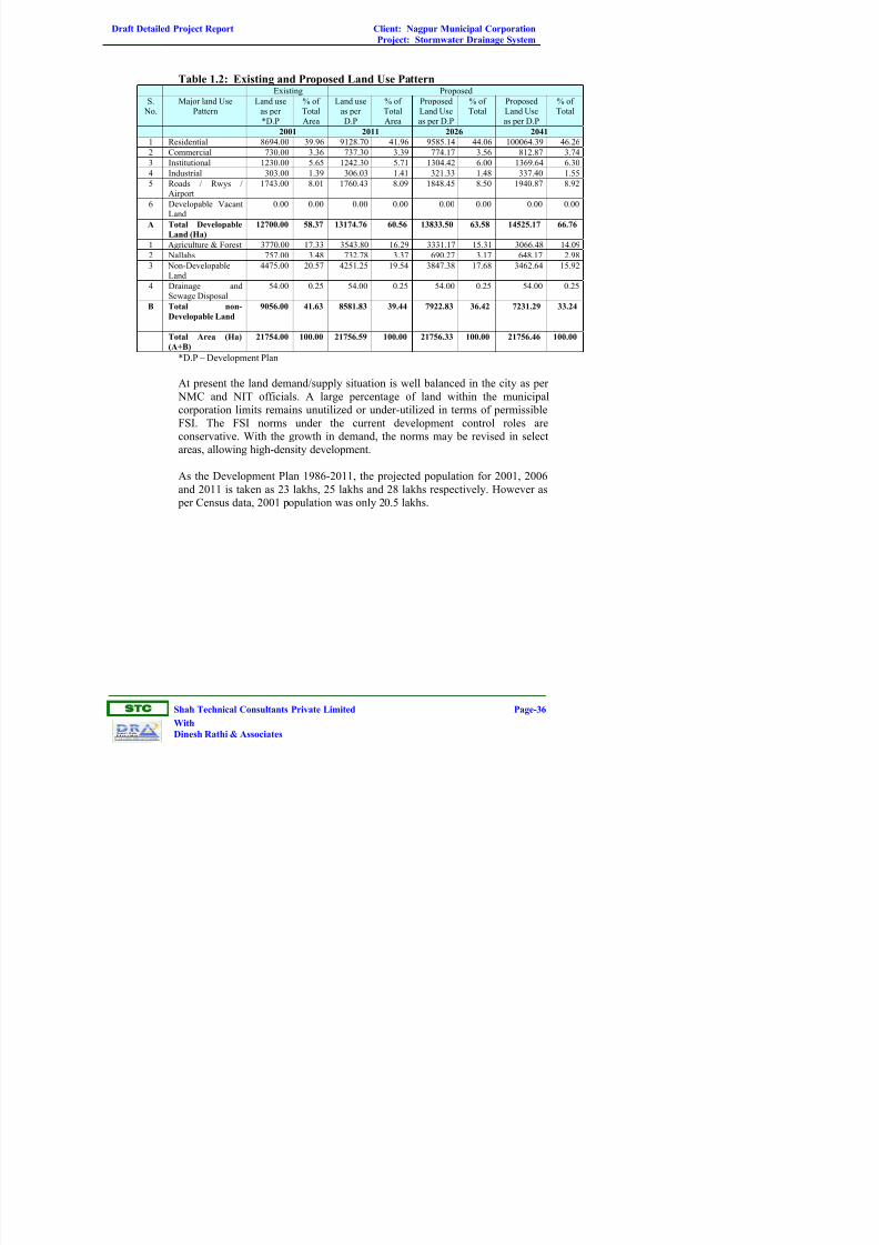
Table 1.2: Existing and Proposed Land Use PatternExisting Proposed
S. No.
Major land UsePattern
Land useas per*D.P
% ofTotalArea
Land useas perD.P
% ofTotalArea
ProposedLand Useas per D.P
% ofTotal
ProposedLand Useas per D.P
% ofTotal
2001 2011 2026 2041
1 Residential 8694.00 39.96 9128.70 41.96 9585.14 44.06 100064.39 46.26
2 Commercial 730.00 3.36 737.30 3.39 774.17 3.56 812.87 3.74
3 Institutional 1230.00 5.65 1242.30 5.71 1304.42 6.00 1369.64 6.30
4 Industrial 303.00 1.39 306.03 1.41 321.33 1.48 337.40 1.55
5 Roads / Rwys /Airport
1743.00 8.01 1760.43 8.09 1848.45 8.50 1940.87 8.92
6 Developable VacantLand
0.00 0.00 0.00 0.00 0.00 0.00 0.00 0.00
A Total Developable
Land (Ha)
12700.00 58.37 13174.76 60.56 13833.50 63.58 14525.17 66.76
1 Agriculture & Forest 3770.00 17.33 3543.80 16.29 3331.17 15.31 3066.48 14.09
2 Nallahs 757.00 3.48 732.78 3.37 690.27 3.17 648.17 2.98
3 Non-DevelopableLand
4475.00 20.57 4251.25 19.54 3847.38 17.68 3462.64 15.92
4 Drainage andSewage Disposal
54.00 0.25 54.00 0.25 54.00 0.25 54.00 0.25
B Total non-
Developable Land
9056.00 41.63 8581.83 39.44 7922.83 36.42 7231.29 33.24
Total Area (Ha)
(A+B)
21754.00 100.00 21756.59 100.00 21756.33 100.00 21756.46 100.00
*D.P – Development Plan
At present the land demand/supply situation is well balanced in the city as per
NMC and NIT officials. A large percentage of land within the municipal
corporation limits remains unutilized or under-utilized in terms of permissible
FSI. The FSI norms under the current development control roles are
conservative. With the growth in demand, the norms may be revised in select
areas, allowing high-density development.
As the Development Plan 1986-2011, the projected population for 2001, 2006
and 2011 is taken as 23 lakhs, 25 lakhs and 28 lakhs respectively. However as
per Census data, 2001 population was only 20.5 lakhs.

Draft Detailed Project Report Client: Nagpur Municipal Corporation
Project: Stormwater Drainage System
ST
Shah Technical Consultants Private Limited Page-37
With
Dinesh Rathi & Associates
8%
24%
1%
15%3%3%
46%
Residental
Commerical
Industrial
public purpose
Public Utility
Itransporation
Recreational
Figure 1.4: Proposed Landuse as per Nagpur Development Plan (1986-
2011)
1.1.2.2 Landuse of Nagpur Metro Region (Phase-I) Land Use plan
The land use plan of Phase-I of Nagpur Metropolitan Region Development
Authority (NMRDA) is prepared by Nagpur Improvement Trust (NIT). The area
of NMR would be 3,780 sq. km. excluding the area under Nagpur Municipal
Corporation (NMC) limits. The total area of Nagpur district is 9,810 sq. km. At
Present NIT has prepared the land use plan for the first phase that covers around
1,520 sq. km. The Metropolitan region is envisaged by government for catering
to Nagpur region population by 2031. At present concentration is on the
southern part because of the MIHAN. Land use plan has earmarked land for
wholesale markets, warehouse, international airport, educational institutes and
Information Technology (IT) parks in these areas.
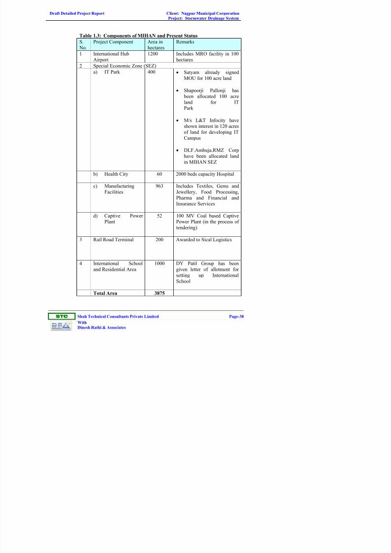
1.1.2.3 Development Area (MIHAN)
The total proposed area of Multi-Modal Hub Airport in Nagpur (MIHAN) is
4025 hectares, out of which 1475 hectares will be used for SEZ. So far 1652
hectares of land is acquired. The acquisition of remaining land is being done on
fast track basis. The components of MIHAN area along with present status is
presented in Table 1.3.
Draft Detailed Project Report Client: Nagpur Municipal Corporation
Project: Stormwater Drainage System
ST
Shah Technical Consultants Private Limited Page-38
With
Dinesh Rathi & Associates
Table 1.3: Components of MIHAN and Present Status
S.
No.
Project Component Area in
hectares
Remarks
1 International Hub
Airport
1200 Includes MRO facility in 100
hectares
2 Special Economic Zone (SEZ)
a) IT Park 400 • Satyam already signed
MOU for 100 acre land
• Shapoorji Pallonji has
been allocated 100 acre
land for IT
Park
• M/s L&T Infocity have
shown interest in 120 acres
of land for developing IT
Campus
• DLF.Ambuja.RMZ Corp
have been allocated land
in MIHAN SEZ
b) Health City 60 2000 beds capacity Hospital
c) Manufacturing
Facilities
963 Includes Textiles, Gems and
Jewellery, Food Processing,
Pharma and Financial and
Insurance Services
d) Captive Power
Plant
52 100 MV Coal based Captive
Power Plant (in the process of
tendering)
3 Rail Road Terminal 200 Awarded to Sical Logistics
4 International School
and Residential Area
1000 DY Patil Group has been
given letter of allotment for
setting up International
School
Total Area 3875

Draft Detailed Project Report Client: Nagpur Municipal Corporation
Project: Stormwater Drainage System
ST
Shah Technical Consultants Private Limited Page-39
With
Dinesh Rathi & Associates
The entire Master Plan is proposed in phases, each generally covering a ten-year
period: 2005-15; 2015-25 and 2025-35. However due to lag in starting the
project, initial phase such as corportisation of airport, awarding the project to
the developer, planning and construction activities could not take place. This
may be due to the land acquisition problems and other issues. However some of
the components of the MIHAN project such as rail and road terminal were
awarded.
There is a sea change in the scenario now as compared to 6 years back with
privatisation of Delhi and Mumbai Airports, which added additional capacities in
terms of passenger and cargo traffic. In addition to that, proposed development
of Greater Noida and Navi Mumbai Airport near Delhi and Mumbai respectively
can absorb future air traffic demand. The commissioning of international
Airports in Hyderabad and Bangalore in early 2008 may also affect the phasing
of the MIHAN project. Hyderabad International Airport, which is only 490 km
from Nagpur is likely to compete directly with MIHAN in attracting both
passenger and cargo traffic. Therefore taking into account above aspects, it is
assumed, MIHAN will be operational by 2015.
Employment Generation due to MIHAN
MIHAN, which comprises of Hub Airport, SEZ and Residential Areas over the
area of 4025 hectares, will generate huge employment. Employment Generated
from MIHAN is estimated taking into account latest proposals of MADC and
Consultants estimates. Table 1.4 shows the Estimates employment from
MIHAN.
Table 1.4: Estimated Employment from MIHAN
Year Airport Centric
Employment
SEZ and Other
Employment
Total
2015 22383 198123 220505
2021 37375 265503 302879
2031 86942 393010 479952 Note: Forecast is based on the premise that MIHAN is operational by 2015.
It can be observed that 1000 hectares of land is allocated for residential purpose
in MIHAN area. This area can house maximum of 6-lakh population taking
residential density of 600 persons/hectare. However significant proportion of
people will still live in Nagpur City and commute on daily basis especially low-
end jobs. This is due to the fact that land in MIHAN area is premium and only
Executives may afford. It is therefore assumed that around 60% the employees
live in MIHAN area and rest of the employees will live in Nagpur City and
commute daily for work.

Draft Detailed Project Report Client: Nagpur Municipal Corporation
Project: Stormwater Drainage System
ST
Shah Technical Consultants Private Limited Page-40
With
Dinesh Rathi & Associates
1.1.2.4 Outer Ring Road
The Public Works Department (PWD) has begun the construction of a part of
Outer Ring Road. The total length of the Outer Ring Road is 84 km. PWD had
acquired 177 hectares land for this road. The total land required for the 84-km
road is 552 hectares.
At present, the 22-km highway is being constructed from Gondhkhairi on
Amaravati Road to Gavsi Manapur on Wardha Road. The alignment of the road
will pass through Gavsi Manapur, Sondapar, Jamtha, Kotewada, Sumthana,
Shiv Madka, Kirimati, Khadka, Sukli, Hingna, Raipur, Wanadongri, Sangam,
Sawargota, Pendhri and Gondkhairi villages. When the Outer Ring Road is
complete it will connect Kalmeshwar, Hingna and Butibori MIDCs. In the first
phase, only two-lane road is being constructed. PWD will spend Rs 41.46 crore
on the project. A 30-km stretch of road - Gavsi Manapur to Kamptee-Kanhan
bypass proposed to be constructed under National Highway Authority of India's
North-South Corridor. Gondhkhairi-Gavsi Manapur stretch will be widened to a
four-lane road under Jawaharlal Nehru National Urban Renewal Mission
(JNNURM). Remaining outer ring road will be constructed by the PWD. The
Outer Ring Road will have ROBs at Tarodi (SEC Railway -Kolkata line),
Jamtha (Central Railway - Bombay line) and Bharatwada (Central Railway -
Delhi line). Department has sent a proposal to the Railway Ministry for
clearance. Railway department is laying 600-mm diameter pipeline for electric
cables.
1.1.3 Occupational Pattern
The employment in the city for future decades are projected based on the
development plan, work force participation ratio in the projected population and
regional plan proposals. The projection of employment for MIHAN is also
considered in estimating the employment in different zones for future years. The
formal employment outside the city includes the employment in Butibori,
Kamptee, Hingna, and MIHAN. Table 1.5 shows the total Employment as per
1991 and 2001 census.
Table 1.5: Total Employment in NMC as per Census
Year Total
Employment
Population Worker
Participation
Ratio
Decadal
Growth %
1991 4,54,953 16,24,752 28.0% -
2001 6,27,481 20,51,320 30.6% 37.9%
Based on trends in other metropolitan cities the worker participation ratio will
increase in future decades. The Worker participation ratio for 2011,2021 and
2031 is likely to be 33%, 35% and 36% respectively. The employment thus
worked out to be 8.5 lakhs, 12.4 lakhs and 16.8 lakhs respectively.

Draft Detailed Project Report Client: Nagpur Municipal Corporation
Project: Stormwater Drainage System
ST
Shah Technical Consultants Private Limited Page-41
With
Dinesh Rathi & Associates
The share of formal employment will decrease as the city grows. The share of
estimated formal employment in 1991 and 2001 is 77% and 75% respectively.
The future share of formal employment for 2011, 2021 and 2031 is assumed as
74%, 70% and 65% respectively. Table 1.6 shows the current and future
employment in NMC area.
Table 1.6: Current and Future Employment in NMC Area
Year Total Employment Formal Employment
1991 454953 350314
2001 627481 472023
2007 743794 551984
2011 855679 614102
2021 141140 869835
2031 1681781 1074975
1.1.3.1 Ward-wise Employment Distribution
The total number of employees working in different zones within the study area
and other locations within the region is an important input for the Travel
Demand Modelling process. Compiled data in this regard was not available
from a single source and hence consultants have to depend on the data from
various sources to arrive at a reasonable estimation of employment distribution.
Consultants have obtained data from Dept. of Industries and MIDC for
industrial employment, NMC for data on shops and establishments and various
other agencies for the respective employment.
The past trend in the employment pattern of the city has been studied from the
data collected from previous studies. The employment projection for the future
decades has been done on the basis of data collected from the Regional Plan,
Dept of industries, MIDC, NMC and Department of Statistics.
The zone wise distribution of employment has been made under 3 categories i.e.
Industrial, Trade and Commerce and Services. The formal employment in areas
outside the city has also been calculated from the details of location of
industries and establishments in the region from regional plans and other
proposed developments. In distributing the employment within the city, it was
assumed that the growth of employment opportunities in the zones along the
proposed Public Transport corridors (BRTS/MRTS) would be higher than other
zones due to higher accessibility to these zones.

Draft Detailed Project Report Client: Nagpur Municipal Corporation
Project: Stormwater Drainage System
ST
Shah Technical Consultants Private Limited Page-42
With
Dinesh Rathi & Associates
1.1.3.2 Schools and Colleges
The list of educational institutions for the base year was collected from various
sources. The zonewise distribution of these institutions was estimated by
assigning the institutions to different zones based on the locations.
For projecting the number educational institution for the horizon years, standards
for different categories were finalised based on the Development Plan, UDPFI
guidelines and existing standards. The additional institutions required for the
future years were distributed on the basis of the set standards so that all zones
meet the criteria for requirement of educational institutions.
The standards adopted for the projection of number of schools and colleges for
the horizon years are as follows:
• Primary School - For every 400 students (for every 2700 population)
• Higher Secondary schools - For every 750 Students (for every 9500
population)
• Junior Colleges and Higher education institutions - for every 12500
population
Based on above discussion employment within NMC and Rest of NMC is
summarised in Table 1.7.
Table 1.7: Population and Employment Forecast NMC & Rest of NMC
NMC Rest of NMC TotalYear
POP EMP POP EMP POP EMP
2001 2052066 472023 539411 188878 2591477 660901
2007 2399337 551984 629260 220263 3028597 772248
2011 2593811 614102 689159 248123 3282971 862225
2021 3548334 869835 1055572 390601 4603906 1260437
2031 4673156 1074975 1447922 535786 6121078 1610760
Note 1: Rest of NMC implies the area between inner ring road and outer ring road
Note 2: Employment figures presented above reefers to only Formal Employment
1.1.4 Ward-wise Details of Drains
Proposed drainage system details are presented in Vol-IIA (Hydraulic
Statement).Details of existing stormwater drainage system is described in the
following paras.

Draft Detailed Project Report Client: Nagpur Municipal Corporation
Project: Stormwater Drainage System
ST
Shah Technical Consultants Private Limited Page-43
With
Dinesh Rathi & Associates
1.1.5 Existing Stormwater Drainage System
1.1.5.1 Major Storm Water Carrying Streams
In Nagpur City, there are 2 major stormwater carrying streams i.e. the Pioli
river, Nag river and Pora river falls outside NMC boundary.
The Pioli river starts from the gate of Gorewada Tank at the northwest end of
the city runs through the north to the eastern end of the city. Final disposal of
stormwater from part of west Nagpur and north Nagpur is into this river through
minor and major Nallahs.
The Nag river starts from Ambazari lake’s overflow weir at the western end of
the city and runs overflow through the middle of the city towards the east. The
final disposal of stormwater from part of west Nagpur, South Nagpur, Central
Nagpur and east Nagpur is into this river through minor and major Nallahs.
Pora river starts from Sonegaon area. Stormwater from southern part of Nagpur
city drains to this river through minor and major Nallahs.
1.1.5.2 Road Side Drains
At present 40% area inside the ring road is covered with stormwater drainage
network. During year 2002 to 2004, stormwater drainage (SWD) network is
developed along the major road constructed under Integrated RoadDevelopment Project (IRDP) in the city. The other developing authority in
Nagpur, Nagpur Improvement Trust is also developed the stormwater drainage
network in various layouts sanctioned in periphery of the existing ring road.
As part of the Master Plan study, an assessment of the existing SWD system has
been made by
• Visual Inspection
• Discussion with NMC Officials
1.1.6 Observations on Existing SWD
• Almost all stormwater drains get flooded during monsoon
• In many places, final disposal of sewage is in the stormwater drain andSWD gets surcharged due to carrying both stormwater and sewage
• Nallahs, rivers, drains and chambers are heavily silted and need cleaning
• Many places, sewers discharge directly into the Pioli river and Nallahs

Draft Detailed Project Report Client: Nagpur Municipal Corporation
Project: Stormwater Drainage System
ST
Shah Technical Consultants Private Limited Page-44
With
Dinesh Rathi & Associates
Table 1.8 shows the Summary of existing stormwater drainage system in north
zone. Table 1.9 shows Area coverage and final disposal point of existing SWD
in north zone .Table 1.10 shows the drainage areas where SWD is joined to
sewerage system and the proposed remedial measure.
Table 1.11 gives the details of flood affected areas in the North Zone and
Proposed remedial measures. Table 1.12 gives the Salient features of Major
Nallah. Table 1.13 gives the Salient features of Minor Nallah. Table 1.14
provides Salient features of Pioli River.

Draft Detailed Project Report Client: Nagpur Municipal Corporation
Project: Stormwater Drainage System
ST
Shah Technical Consultants Private Limited Page-45
With
Dinesh Rathi & Associates
Table 1.8: Summary of Existing Stormwater Drainage System – North Zone
Drain Size (Range)
WardArea
covered (%)Drain material
Channel Size (m)Pipe Dia.
(mm)
Chamber
material
Chamber size (Range)
(m)
Total no of
Chambers
Chambers
in goodcondition
Disposal Point
1 10 RCC/ Unlined 0.6x0.75-0.9x2.2 225-300 BC 0.7 x 0.8- 1.20 x 0.9 288 1261 Pioli/Nallah/Open
2 30RCC
0.25x0.25-1.2x1.2 225-750BC 0.75 x 0.75
-1.80 x 1.20114 93 Pioli/Nallah/Open
3 10 RCC 0.15x0.15-1x1.8 300-450 BC 0.9x0.6-1.50 x 1.20 47 32 Pioli/Nallah/Open
4 25 RCC 0.4x0.3-1x1.1 300 BC 0.75x0.75-1.20 x 1.80 163 137 Nallah/Open/SWMH*
5 10 RCC/Stone 0.3x0.2-0.85x0.65 150-1200 BC 0.75 x 0.75-1.70 x 1.70 136 128 Nallah/Open/SWMH
6/P 10 RCC 0.5x0.3-0.8x0.65 300-1200 BC 0.5 x 0.90-1.70 x 1.70 122 112 Nallah/Open
17 5 RCC/Unlined 0.3x0.3-1x1 300-600 BC 0.6x0.7-1.2x0.9 236 214 Nallah/Open/SWMH
18 15 RCC 0.3x0.3-0.9x1.1 150-450 BC 0.9x0.75-1.2x0.9 232 224 Nallah/Open/SWMH
19 15 RCC 0.3x0.3-1x0.9 BC 1.2x0.9 43 40 Nallah/Open/SWMH
20 35 RCC 0.2x0.3-1.2x1.0 150-300 BC 0.5 x 0.9-1.5 x 1.20 353 311 Nallah/Few Open
21 40 RCC/Unlined 0.2x0.1-1.2x1.1 100-600 BC 0.75 x 0.6-1.20 x 0.9 20 16 Nallah/SWMH
22 50 RCC 0.5x0.4-1.1x0.8 300-450 BC 0.5 x 0.9-1.50 x 1.20 60 47 Nallah/SWMH
23 20 RCC 0.2x0.2-1.2x1.0 150-500 BC 0.5 x 0.9-1.50 x 1.20 39 36 Nallah
24 10 RCC 0.45x0.45-1.2x1.0 300 BC 0.75 x 0.75-1.50 x 1.20 119 115 Nallah /SWMH/Open
25 15 RCC 1.0x0.6-1.0x0.9 225-330 BC 0.9 x 0.75-1.50 x 1.20 77 72 Nallah /SWMH
26 15 RCC 0.3x0.4-1.1x0.9 - BC 1.20 x 1.20 5 4 Nallah /Out fall
27 5 RCC 0.3x0.2-1.0x0.9 - BC 1.20 x 1.50 7 5 Nallah/Pond/SWMH/Open
28 40 RCC 1.0x0.8-1.1x0.9 225-450 BC 0.75 x 0.75-1.50 x 1.20 55 42 Nallah /SWMH
29 40 RCC 0.25x0.25-0.3x0.2 - BC 0.9 x 0.75-1.20 x 0.9 290 230 Nallah
30 5 RCC 0.3x0.2-1.0x1.5 225-300 - - - - Nallah /Open
31 15 RCC 0.75X0.6-1.0X0.7 - BC 1.2X1.2 2 2 Nallah /Open
55/P 5 RCC/Unlined 0.2x0.3-1.0x0.6 - - - - - Nallah
56 10 RCC 0.2x0.3-1.0x0.6 225-300 BC 1.20 x 0.9 8 6 Nallah /Open
57 15 RCC 0.2x0.3-1.0x0.9 - BC 0.9x0.75-1.20x1.20 14 10 Nallah /SWMH
58 10 RCC 0.2x0.15-1.2x0.9 BC 1.20x0.8-1.20x1.20 33 27 Nallah /Out fall

Draft Detailed Project Report Client: Nagpur Municipal Corporation
Project: Stormwater Drainage System
ST
Shah Technical Consultants Private Limited Page-46
With
Dinesh Rathi & Associates
Drain Size (Range)
WardArea
covered (%)Drain material
Channel Size (m)Pipe Dia.
(mm)
Chamber
material
Chamber size (Range)
(m)
Total no of
Chambers
Chambers
in good
condition
Disposal Point
59 40 RCC 0.3x0.3-1.2x1.1 225-600 BC 1.00 x 0.9-1.50 x 1.40 10 8 Nallah /Open Out fall
60 35 RCC 0.15x0.15-1.2x1.0 225-300 BC 0.75 x 0.75-1.50 x 1.20 25 18 Nallah
61 50 RCC 0.2x0.3-2.1x1.1 225-300 BC 0.75 x 0.75-1.10 x 1.00 16 10 Nallah
62 5 RCC 0.7x0.2-1.2x1.1 150-225 BC 0.75 x 0.7-1.50 x 1.20 5 5 Nallah /Open
63 15 RCC 0.25x0.3-1.2x1.0 - BC 0.75 x 0.7-1.50 x 1.20 4 4 Nallah /SWMH
64 35 RCC 0.5x0.4-1.1x0.9 225-450 BC 0.5 x 0.50-1.50 x 1.20 130 256 Nallah /SWMH/Out fall
65 50 RCC 0.5x0.4-1.1x0.9 225-900 BC 0.9 x 0.75-1.50 x 1.20 109 97 Nallah /SWMH
66 - - - - - - - - -
67 10 RCC 0.4x0.5-0.9x0.7 225-600 BC 0.9 x 0.9-1.50 x 1.20 27 25 Nallah /SWMH
68 70 RCC 0.4x0.45-0.9x0.7 225-500 BC 0.75 x 0.75-1.50 x 1.20 118 98 Nallah /SWMH/Out fall
69 55 RCC 0.25x0.25-1.0x0.8 225-300 BC 0.5 x 0.90-1.50 x 1.20 184 167 Nallah
70 - RCC - - - - - - -
86/P 50 RCC 0.7x0.5-1.0x0.9 - - - - - Nallah
87/P 20 RCC 0.15x0.15-1.0x1.1 - BC 1.20x1.20 15 13 Nallah/Open
88 50 RCC 0.15x0.15-1.4.0x0.5 - - - - - Nallah
89 30 RCC 1.0x0.75-1.2x0.9 300 BC 0.75 x 0.75-1.10 x 1.10 134 113
90 40 RCC 0.25x0.25-1.2x0.9 - - - - - Nallah /SWMH/Open
91 20 RCC 0.5x0.4-1.0x0.9 150-300 BC 0.5 x 0.90-1.50 x1.20 47 43 Nallah /SWMH
92 5 RCC 0.3x0.30 - - - - - SWMH
93 10 RCC 0.3x0.3-1.25x0.75 150-300 BC 0.75 x 0.75-1.20 x 1.20 17 14 Talav/SWMH
94/P 10 RCC 0.45x0.6-1.0x0.6 - BC 0.9 x 0.10-1.50 x 1.20 4 2 Nallah /SWMH
109 25 RCC 0.15x0.15-0.9x1.0 - - - - - Nallah
110 2 RCC 0.3x0.2-0.9x1.0 - - - - - Nallah
111 5 RCC - BC 0.9 x 0.9 10 8 SWMH
112 30 RCC 0.25x0.3-0.4x0.6 BC 0.5 x 0.90-1.50 x 1.20 4 3 SWMH
113 20 RCC 0.6x0.4-0.9x1.0 BC 0.5 x 0.90-1.50 x 1.20 12 10 SWMH/Nallah/Out fall
114/P 15 RCC 0.7x0.5-1x0.6 300 BC 1.20 x 0.9-1.20 x 1.20 5 4 Nallah/Out fall
124 - - - - - - - - -
125 30 RCC 0.9x1.0-0.7x0.4 - BC 0.5 x 0.90-1.20 x 1.20 11 10 Nallah

Draft Detailed Project Report Client: Nagpur Municipal Corporation
Project: Stormwater Drainage System
ST
Shah Technical Consultants Private Limited Page-47
With
Dinesh Rathi & Associates
Table 1.9: Area Coverage of Existing Stormwater Drainage System in North Zone
Ward No Area covered by existing system Final disposal
1 Jhingabaitekly Nagar, Goregowda village
2 Kalpana nagar, Kabir nagar, sugath nagar, Hudco colony, Viswas nagar, Krushi
nagar
Partially open area disposal, nallah disposal
and sewage manhole disposal
3 Santhos nagar, Vinobha nagar, Nageswar nagar, Kamkar nagar, Kapil nagar,
Ramay nagar, Samrat nagar, Naribasti slum area, Wanjri, Ambetkar nagar, Pioli
village
Nallah disposal and Open area disposal
4 Yadav nagar, Prakash nagar, Sangam Nagar, Sangeevan nagar, Yahoda nagar,
Vinijri village, Shiva shankti nagar, Sangharh nagar, NIT quatres, Aravind nagar,
Pawan nagar, ramana nagar
Nallah disposal, Open area disposal and few
lines are connected to sewage manhole
5 Kalmana village Nallah disposal and few open area disposal
6 Surya nagar, Netaji nagar, Gujarat colony, Jalaram nagar Major pipelines disposal to nallah and few
lines to open area disposal
17 Thekkadi, Sariputra nagar layout, New jagruti colony, Jagruti colony, Dabha
village, New hazari pahad nagar, friends colony, kolbaswamy nagar, Veenvan
colony, Akbar layout, Jagdish nagar, Makardhokda, Kpileswar nagar
Partially open area disposal, nallah disposal
and few sewage manhole disposal
18 Patel nagar, Manasa sarowar colony, Amant nagar, Swagat nagar, Kapileswar
nagar
Nallah disposal and Open area disposal
19 Shilpa nagar, Gittikadan basti, Pension nagar, police lines, samdhan nagar,
Kamgar nagar
Open area disposal and few manhole, Nallah
disposal
20 Rajnagar Nallah disposal few open area disposal and
few sewage manhole disposal
21 Byramji town (Rec.area), Manav nagar, Chawoni chowk Open area disposal and few sewage manhole,
Nallah disposal
22 Gvind nagar, bank colony, Jaripatka, satyanand nagar, Arun nagar Nallah disposal few open area disposal and
few sewage manhole disposal
23 Republican nagar, Bada Indor missal layout, Amarjyoti nagar, Ahhuja nagar,
nagasen nagar, mishal layout
Nallah disposal

Draft Detailed Project Report Client: Nagpur Municipal Corporation
Project: Stormwater Drainage System
ST
Shah Technical Consultants Private Limited Page-48
With
Dinesh Rathi & Associates
Ward No Area covered by existing system Final disposal
24 Siddarth nagar, Shinde nagar, manav nagar, Angtimala, satyog nagar, Prabhat
colony, Taware nagar (colony)
Partially open and partially nallah disposal
25 Mahendra nagar, babu buddaji nagar, Habeeb nagar Partially open and partially nallah disposal
26 Indiramata nagar, Panchavati nagar, Dharmadeep nagar, sanjay gandthi nagar,
Anand nagar
Partially open and partially nallah disposal
27 Binaki mangalwari village, Kundala gupa nagar, Brindavan nagar, Jamdthar
wadi
Nallah disposal
28 Premnagar Nallah disposal
29 Shanti nagar Nallah disposal
30 Surya nagar, Dipti signal
31 Minimata nagar Open area disposal
55 Ravi nagar Nallah disposal
56 CPWD quarters, Rajiv colony, Govind gorkhade layouts, Surendra gate Nallah Disposal and few Sewage manhole
disposal
57 CPWD quarters, Gowlipura, Kadhan, Gondpurinagar, Bijji nagar, P&T colony Nallah Disposal and few Sewage manhole
disposal
58 Gawali pura, Sardar village Open area and Nallah disposal (mostly)
59 Newbasti
60 Cristian colony, lumbini nagar, Ambetkar nagar, Bensiion bagh nagar
61 Indora Nallah disposal
62 Chocks colony, Audenagar, maya nagar, Indora village, Republican nagar Nallah Disposal and few Sewage manhole
disposal
63 Ashok nagar, Buddha nagar Nallah Disposal and few Sewage manhole
disposal
64 Milind nagar basti, Baba budda nagar, Taj nagar Open area and Nallah disposal (mostly)
65 Vishali nagar, Jhipura, Bholinagar, panchasheel nagar Open area disposal
66 Bangladesh nayak wadi, Nayak talav
67 Khairipura Nallah Disposal and few Sewage manhole

Draft Detailed Project Report Client: Nagpur Municipal Corporation
Project: Stormwater Drainage System
ST
Shah Technical Consultants Private Limited Page-49
With
Dinesh Rathi & Associates
Ward No Area covered by existing system Final disposal
disposal, open disposal
68 Bastarwari Nallah Disposal and few Sewage manhole
disposal
69 Netaji Subash Chandra pose ward Nallah disposal and few open area disposal
88 laskanbagh
89 Kamal chowk, gurunanak pura, Nvanaksa, Motibagh road, Gurunanak nagar Nallah disposal
90 Kurkatkarpeth, Ambetkar nagar, Buslewadi Nallah disposal and few line open area
disposal
91 Sweeper colony, Balbahu peth Nallah disposal
92 Adar winker colony, thanda pet Partially nallah and partially open area
disposal
93 Lendi Thalao (overflow) Nallah disposal

Draft Detailed Project Report Client: Nagpur Municipal Corporation
Project: Stormwater Drainage System
ST
Shah Technical Consultants Private Limited Page-50
With
Dinesh Rathi & Associates
Table 1.10: Drainage area where SWD is joined to sewerage System and
Proposed remedial Measure
S.
No.
Ward
No
Area Drain Size Remedial Measure
1 2 Kalpana Nagar 300 Alternate drain proposed
2 4 Gareeb Nawaz Nagar 300 Connect to nearby Nallah
3 Sugath Nagar 225 Alternate drain proposed
4 5 Chikl Nagar 225 Alternate drain proposed
5 6 Sevasreenagar 800x600 Connect to nearby Nallah
6 Bharat Nagar 800x600 Connect to nearby Nallah
7 17 Friends Colony 300 Connect to Proposed Network
8 Makardhokada 300x300 Connect to Proposed Network
9 18 Gandhi Layout 150 Alternate drain proposed
10 19 Lekha Apartment 300X300 Connect to nearby Nallah
11 21 Vijay Nagar 600 Connect to Proposed Network
12 Chaaoni 450 Connect to Proposed Network
13 22 Juna Jaripatka 225 Alternate drain proposed
14 Sri Basavansha Chowk 500X400 Connect to nearby Nallah
15 24 Sathyog Nagar 300 Connect to nearby Nallah
16 Sathiyog Nagar 300 Connect to nearby Nallah
17 Sathyog Nagar 300 Connect to nearby Nallah
18 25 Takanagar Basti 225 Alternate drain proposed
19 Shorakati Shanthi Nagar 300 Connect to nearby Nallah
20 Shorakati Shanthi Nagar 1000x900 Connect to nearby Nallah
21 Shorakati Shanthi Nagar 1000x900 Connect to nearby Nallah
22 Shorakati Shanthi Nagar 1000x900 Connect to nearby Nallah
23 Mahendra Nagar 900X800 Connect to nearby Nallah
24 26 Panchavadi Nagar 1000X900 Connect to nearby Nallah
25 27 Indra Gandhi Colony 1000x900 Connect to nearby Nallah
26 Binaki Mangalwari
Village
700X600 Connect to nearby Nallah
27 Rani Durgawati Nagar 1100 Connect to nearby Nallah
28 28 Gondpura Balster Wadi 300 Alternate drain proposed
29 Prem Nagar Chowk 300 Alternate drain proposed
30 Prem Nagar Chowk 300 Alternate drain proposed
31 57 C.P.W.D Quarters 300x400 Alternate drain proposed
32 Seminary Hills 300x300 Alternate drain proposed
33 Gondpuri Nagar 150X150 Alternate drain proposed
34 Gondpuri Nagar 150X150 Alternate drain proposed
35 Bijli Nagar 225 Alternate drain proposed
36 63 Ashoka Nagar 225X225 Connect to nearby Nallah
37 64 Vaishali nagar 1100X900 Connect to nearby Nallah
38 65 Juna Jaripatka 900X600 Connect to nearby Nallah
39 67 Khairipura 900x700 Connect to nearby Nallah
40 Gondpura 600 Connect to nearby Nallah

Draft Detailed Project Report Client: Nagpur Municipal Corporation
Project: Stormwater Drainage System
ST
Shah Technical Consultants Private Limited Page-51
With
Dinesh Rathi & Associates
S.
No.
Ward
No
Area Drain Size Remedial Measure
41 68 Lal Kanjku Jri Chowk 500 Connect to Proposed Network
42 Gondpura Balster Wadi 500 Alternate drain proposed
43 90 Kururkar Peth Slums 300X200 Alternate drain proposed
44 91 Sweeper Colony 150 Alternate drain proposed
45 92 Thanda Pet 300X300 Alternate drain proposed
46 94 Bank Of Maharashra 600x700 Connect to Proposed Network
47 111 Timki Slums 225 Alternate drain proposed
48 112 Base Nagar 600X400 Connect to Proposed Network
49 Base Nagar 300X300 Connect to Proposed Network
50 Shobha Keth Nagar 300X300 Connect to Proposed Network
51 Base nagar 350x300 Connect to Proposed Network
52 Shabha keth Nagar 250X300 Connect to Proposed Network
53 113 Dewkar Pura 600X500 Connect to Proposed Network

Draft Detailed Project Report Client: Nagpur Municipal Corporation
Project: Stormwater Drainage System
ST
Shah Technical Consultants Private Limited Page-52
With
Dinesh Rathi & Associates
Table 1.11: Flood affected Area in the North Zone and Proposed Remedial Measure
S.
No.
Pt.
No.
Location of the submergence Ward
No.
Name of the disposal
point
Reasons for stagnation of
water or Flooding
Remedial Measures
1 2 3 4 5 6 7
1 P 1 Jajadish nagar near Khadan 17 Bor Nallah Pond flooding Deepening and Widening of
Nallah
2 P 2 Bor Nallah Slum 17 Bor Nallah Low lying area Adequate drainage system
proposed
3 P 3 Krishna Nagar / Azad Nagar 57 Bor Nallah Pond flooding Deepening and Widening of
Nallah
4 P 4 Sheela Nagar Katol road 19 Bor Nallah Low lying area Adequate drainage system
proposed
5 P 5 Dasharath Nagar Gorewada road 19 Bor Nallah Pond flooding Deepening and Widening of
Nallah
6 P 6 Dhore layout , Mankapur 20 Pioli River Nallah flooding Deepening and Widening of
Nallah
7 P 7 Mankapur basti near Pioli River 20 Pioli River River flooding River Bed deepening /
widening
8 P 8 Zingabai Takli near Pioli River 1 Pioli River River flooding River Bed deepening /
widening
9 P 9 Bajarang Nagar, Zingabai Takli 1 L2 Nallah Low lying area
10 P 10 Indira Nagar (Newly identified
slum)
2 Pioli River Low lying area, Drainage
system does not exist
Drainage system proposed
11 P 11 Kushi Nagar 2 Pioli River Low lying area,
insufficient drainage
system
Adequate drainage system
proposed
12 P 12 Bhadant Anand kausalyan Nagar
(Notified slu22m)
3 Pioli River Low lying area, Drainage
system does not exist
Drainage system proposed,
River Bed Widening

Draft Detailed Project Report Client: Nagpur Municipal Corporation
Project: Stormwater Drainage System
ST
Shah Technical Consultants Private Limited Page-53
With
Dinesh Rathi & Associates
S.
No.
Pt.
No.
Location of the submergence Ward
No.
Name of the disposal
point
Reasons for stagnation of
water or Flooding
Remedial Measures
1 2 3 4 5 6 7
13 P 13 Bezonbagh behind Mahatma
Gandhi School
61 Chamar nallah Insufficient drainage
system
Adequate drainage system
proposed
14 P 14 Wadpakhad (baba Indora slum) 22 Chamar nallah Low lying area, raising of
cement road surface, short
nallah width
Adequate drainage system
proposed, Widening and
Deepening of Nallah
15 P 15 Jagrut Nagar 2 & 24 Chamar nallah Low lying area, Adequate drainage system
proposed
16 P 16 Ramai nagar (Notified slum) 3 Chamar nallah Low lying area, raising
the level of Ring of road
Adequate drainage system
proposed
17 P 17 Gulshan Nagar 5 Pioli River Flooding of Pioli River River Bed Widening
18 P 18 Basti Adjoining Bridge over Pioli
River near Kalumna
5 Pioli River Flooding of Pioli River River Bed Widening
19 C1 Goa Colony behind Govt.
Polytechnic
59 Chamar Nallah Low lying area Adequate drainage system
proposed
20 C2 Pardesi Mohalla Gaddigodam 59 Chamar Nallah Low lying area Adequate drainage system
proposed
21 C3 Kamptee road near Nagpur bar 59 Chamar Nallah Low lying area Adequate drainage system
proposed
22 C4 Dobi Nagar 109 &
110
Chamar Nallah Low lying area and cattle
waste thrown in nallah
Adequate drainage system
proposed
23 C5 Khadan Adiwasi Nagar 21 Chamar Nallah Low lying area Adequate drainage system
proposed
Draft Detailed Project Report Client: Nagpur Municipal Corporation
Project: Stormwater Drainage System
ST
Shah Technical Consultants Private Limited Page-54
With
Dinesh Rathi & Associates
S.
No.
Pt.
No.
Location of the submergence Ward
No.
Name of the disposal
point
Reasons for stagnation of
water or Flooding
Remedial Measures
1 2 3 4 5 6 7
24 C6 Christian Colony Lumbini Nagar 60 Chamar Nallah Low lying area Adequate drainage system
proposed
25 C7 Indira Mata Nagar 26 Chamar Nallah Inadequate Section Adequate drainage system
proposed
26 C8 Dhamma Deep Nagar near H/o
Shri Gajbhiye
26 Chamar Nallah Inadequate section Adequate drainage system
proposed
27 C9 Near Zunka Bhakar Kendra,
Mehandibagh road on ring road
27 Chamar Nallah Inadequate drainage Adequate drainage system
proposed
28 C10 Kundanlal Gupta nagar near ring
road
27 Chamar Nallah Low lying area and
inadequate stormwater
drain
Adequate drainage system
proposed
29 C11 Near Mangalwari Talao 27 Chamar Nallah Low lying area, and
inadequate stormwater
drain
Adequate drainage system
proposed
30 SH1 Lendi Talao, Musalmanpura,
Tumdipura
94 Shanti Nagar Nallah Low lying area and
encroachment of
hutments in talao
catchment
Adequate drainage system and
Removal of encroachment
proposed
31 SH2 Near Pratibha School Khairipura 67 Shanti Nagar Nallah Low lying area and
insufficient stormwater
drain
Adequate drainage system
proposed

Draft Detailed Project Report Client: Nagpur Municipal Corporation
Project: Stormwater Drainage System
ST
Shah Technical Consultants Private Limited Page-55
With
Dinesh Rathi & Associates
S.
No.
Pt.
No.
Location of the submergence Ward
No.
Name of the disposal
point
Reasons for stagnation of
water or Flooding
Remedial Measures
1 2 3 4 5 6 7
32 SH3 Near 40 Laterines 29 Shanti Nagar Nallah Low lying area Adequate drainage system
proposed
33 SH4 Near MSEB Office 29 Shanti Nagar Nallah Low lying area Adequate drainage system
proposed
34 SH5 Shanti Nagar Hsg. Board Colony
on old Kamptee road near
Kuttewala Baba Ashram
28 Shanti Nagar Nallah Insufficient capacity of
nallah
Widening and Deepening of
Nallah proposed
35 SH6 Ghat Chowk to Kawrapeth
Railway line
29 Shanti Nagar Nallah Insufficient capacity of
nallah
Widening and Deepening of
Nallah proposed

Draft Detailed Project Report Client: Nagpur Municipal Corporation
Project: Stormwater Drainage System
ST
Shah Technical Consultants Private Limited Page-56
With
Dinesh Rathi & Associates
Table 1.12: Salient Features of Major Nallahs in North Zone
S.No. Nomenclature /
Name of NallahCoverage Area
Length
of
Nallah
(m)
Existing
Width of
Nallah
(m)
Existing
Depth of
Nallah (m)
Catchment
area (ha)
Minor
Nallahs
Joining
Outfall
Orignates at: Gorewada
Passes through: Madhav Ashram1 L1
Joins Pioli River at: Chainage 2062m
2702 3.0 - 44.0 0.26 - 2.19 973 -
Orignates at: Shri Krishna Nagar
Passes through: Sadbhavna Nagar, Geeta
Nagar:Tirupati Nagar, Veda Nagar2
L2
(VED NAGAR
NALLAH)Joins Pioli River at: Aradhana Colony
3210 2.1 - 16.0 0.72 - 3.6 375 1
Orignates at: Pokara village
Passes through: Nara village3L3
(NARA NALLAH)Joins Pioli River at: Chainage 6953m
3545 5.4 - 26.0 0.46 - 2.44 755 2
Orignates at: Cultivated land
Passes through: Fathima Nagar, Uppal
Wadi4 L4
Joins Pioli River at: Kalmana Village
10160 6.0 - 20.0 0.25 - 3.55 1105 1
Orignates at: Marshy land
Passes through: NMC Water Treatment
Plant5 R1
Joins Pioli River at: Chainage 490m
500 4.0 - 14.0 1.29 - 1.75 98 -
Orignates at: Gowtham Nagar
Passes through: Hajari Pahad, Aakar
nagar, Kolba Swamy Nagar, Defence
Land, Prashant Layout
6R2
(BOR NALLAH)
Joins Pioli River at: Ayappa Nagar
6225 3.1 - 25.0 0.3 - 3.3 1362 9
Pioli River

Draft Detailed Project Report Client: Nagpur Municipal Corporation
Project: Stormwater Drainage System
ST
Shah Technical Consultants Private Limited Page-57
With
Dinesh Rathi & Associates
S.No. Nomenclature /
Name of NallahCoverage Area
Length
of
Nallah
(m)
Existing
Width of
Nallah
(m)
Existing
Depth of
Nallah (m)
Catchment
area (ha)
Minor
Nallahs
Joining
Outfall
Orignates at: Timki nagar
Passes through: Lashkari Bagh, Jyothi
nagar, Boudha Nagar, Sanjay Gandhi
Nagar, Dharma Deep Nagar, Panchsheel
Nagar
7R3
(Chamar Nallah)
Joins Pioli River at: Sangam Nagar
5610 4.0 - 42.0 0.15 - 5.8 1737 6
Orignates at: P & T Colony
Passes through: Police Lines, Awasthi
Nagar, Prasanth Nagar8 R4
Joins Pioli River at: Ambuth Colony
3080 1.6 - 17.0 0.84 - 4.75 317 -
Orignates at: Gyaneshwar Nagar9 R5
Joins Pioli River at: Chainage 4550m180 4.5 - 6.5 0.6 - 1.49 59 -
Orignates at: Manakapura
Passes through: Gyaneshwar Nagar10 R6
Joins Pioli River at: Chainage 4816m
710 1.8 - 7.0 0.58 - 1.74 22 -
Orignates at: Juna Jaripatka
Passes through: Bhim Nagar, Saint Martin
Nagar, Kasturba Nagar, Jaripatka Nagar,
Taj Nagar
11
R7
(TAJ NAGAR
NALLAH)
Joins Pioli River at: Chainage 5676m
2270 1.2 - 8.25 0.5 - 3.28 60 -
Orignates at: Sai Julelal Marg:12 R8
(VISHWAS NAGAR Passes through: Viswas Nagar Nagar
570 2.5 - 3.8 1 - 4.5 27 -
Pioli River

Draft Detailed Project Report Client: Nagpur Municipal Corporation
Project: Stormwater Drainage System
ST
Shah Technical Consultants Private Limited Page-58
With
Dinesh Rathi & Associates
S.No. Nomenclature /
Name of NallahCoverage Area
Length
of
Nallah
(m)
Existing
Width of
Nallah
(m)
Existing
Depth of
Nallah (m)
Catchment
area (ha)
Minor
Nallahs
Joining
Outfall
NALLAH) Joins Pioli River at: Viswas Nagar
Orignates at: Santosh Nagar
Passes through: Nagsenwan Nagar,
Vaishnu Devi Nagar, Gulshan Nagar13 R9
Joins Pioli River at: Kalamana
1830 12 - 18.5 1.01 - 2.65 137 -
Orignates at: Netaji Subhash Chandra
Bose ward
Passes through: Prem Nagar, Shanti
Nagar, Dipti Signal, Pardi14
R10
(SHANTINAGAR
NALLAH)
Joins Pioli River at: Chainage 17635m
7710 5.0 - 17.0 1 - 2.79 795 6 Pioli River

Draft Detailed Project Report Client: Nagpur Municipal Corporation
Project: Stormwater Drainage System
ST
Shah Technical Consultants Private Limited Page-59
With
Dinesh Rathi & Associates
Table 1.13: Salient Features of Minor Nallahs in North Zone
S.
No.
Nomenclature /
Name of NallahCoverage Area
Length of
Nallah (m)
Existing
Width of
Nallah (m)
Existing
Depth of
Nallah (m)
Outfall
Orignates at: Prasanth Nahar
Passes through: Manodha Nagar, Prem Nagar, Swami Vrijananda
Nagar1 L2/R1
Joins L2 at: Nara Colony
2580 4.0 - 15.0 0.4 - 1.9 L2
Orignates at: Open Area
Passes through: cultivated Land2 L3/L1
Joins L3 at: Nara Village
1445 2.1 - 6 0.8 - 1.4 L3
Orignates at:Pokara village3 L3/L2
Joins L3 at: Chainage 545m720 2.0 - 4.0 0.9 - 1.5 L3
Orignates at: Tiwari Nagar
Passes through: Cultivated Land4 L4/R1
Joins L4 at: Chainage 4593m
1465 4.0 - 9.0 0.5 - 1.6 L4
Orignates at: Police Line Takli
Passes through: Pension nagar, ahbab Nagar, Netaji Nagar, Anand
Nagar5 R2/L1
Joins R2 (Bor Nallah) at: Swagath Nagar
1520 1.2 - 5.5 0.4 - 2.3 R2
Orignates at: Vishwas Nagar
Passes through: Kadhan, Slum Area, Military Area, Anant Nagar,
Patil Nagar, Boregaon Slums6 R2/L2
Joins R2 (Bor Nallah) at: Prashant Layout
1580 1.7 - 9.5 0.5 - 2.8 R2
Orignates at: Surendra Nagar
Passes through: Surendra Ghat, Slum Area, Hajaripahad7 R2/L3
Joins R2 (Bor Nallah) at: Defence Land (Restricted Area)
1930 1.8 - 9.6 0.4 - 2.0 R2
8 R2/L4 Orignates Near: Veterinary College 980 2.2 - 10.0 0.4 - 2.4 R2
Draft Detailed Project Report Client: Nagpur Municipal Corporation
Project: Stormwater Drainage System
ST
Shah Technical Consultants Private Limited Page-60
With
Dinesh Rathi & Associates
S.
No.
Nomenclature /
Name of NallahCoverage Area
Length of
Nallah (m)
Existing
Width of
Nallah (m)
Existing
Depth of
Nallah (m)
Outfall
Passes through: Manavslva Nagar
Joins R2 (Bor Nallah) at: Akar Nagar
Orignates Near: Haed Qtrs of India Airforce Maintenance Command
Passes through: New hajari Pahad Nagar9 R2/L5
Joins R2 (Bor Nallah) at: Chainage 1711m
450 2.4 - 4.8 0.5 - 1.3 R2
Orignates at: Open Area10 R2/L7
Joins R2 (Bor Nallah) at: Chainage 342m125 2.2 - 3.2 0.2 - 1.2 R2
Orignates at: Jagadish Nagar
Passes through: Makar Dhokada11 R2/R1
Joins R2 (Bor Nallah) at: Chainage 3388m
1050 3 - 6.2 0.6 - 2.4 R2
Orignates at: Open Area
Passes through: Ganga Nagar12 R2/R2
Joins R2 (Bor Nallah) at: Chainage 1092m
580 2.6 - 7.2 0.6 - 1.8 R2
Orignates at: Open Area13 R2/R3
Joins R2 (Bor Nallah) at: Chainage 504m380 1.2 - 2.5 0.5 - 0.8 R2
Orignates at: Kumbhar Pura
Passes through: Slums, Tandapeth, Milind Nagar Basthi, Ashoka
Nagar14 R3/L1
Joins R3 (Chamar Nallah) at: Mahendra Nagar
1440 2.4 - 10.2 1.1 - 4.0 R3
Orignates at: Lashkaribagh
Passes through: Moti Bagh, Nawa Nakasha15 R3/L2
Joins R3 (Chamar Nallah) at: Gurunanak Pura
810 1.0 - 3.0 0.7 - 4.2 R3
Orignates at: Shahid Hemu Chowk16 R3/R1
Passes through: Slums, Nagasen Nagar, Siddarth Nagar, Kamgar
Nagar, Sangharsh Nagar, Ramna Nagar (Slums), Shiv Shakti Nagar
4375 3.4 - 9.0 0.4 - 2.9 R3

Draft Detailed Project Report Client: Nagpur Municipal Corporation
Project: Stormwater Drainage System
ST
Shah Technical Consultants Private Limited Page-61
With
Dinesh Rathi & Associates
S.
No.
Nomenclature /
Name of NallahCoverage Area
Length of
Nallah (m)
Existing
Width of Nallah (m)
Existing
Depth of Nallah (m)
Outfall
Joins R3 (Chamar Nallah) at: Yasodhara Nagar
Orignates at: Chhaoni
Passes through: Mecosa Bagh, Bezonbagh, Nayee Basti17 R3/R2
Joins R3 (Chamar Nallah) at: 10 No. Puliya Chowk
1775 1.6 - 18 0.6 - 2.9 R3
Orignates at: Nayee Basti
Passes through: Punjabi Nagar, Bezonbagh18 R3/R3
Joins R3 (Chamar Nallah) at: Moti Bagh
1430 1.1 - 9.0 0.6 - 4.5 R3
Orignates at: Moti Bagh19 R3/R4
Joins R3 (Chamar Nallah) at: Chainage 2382m330 3.4 - 4.5 1.0 - 1.3 R3
Orignates at: Shivaji Chowk
Passes through: Sanjay Nagar20 R10/L1
Joins R10 (Shantinagar Nallah) at: Chainage 2350m
230 1.8 - 2.1 0.8 - 1.1 R10
Orignates at: Vairagade Badi
Passes through: Sanjay Nagar, Dipti Signal21 R10/L2
Joins R10 (Shantinagar Nallah) at: Chainage 3860m
580 1 - 1.3 0.5 - 1.8 R10
Orignates at: Netaji Subhash Nagar Bose ward
Passes through: Vairagade Badi22 R10/L3
Joins R10 (Shantinagar Nallah) at: Shanti Nagar
1190 6 - 16.5 0.8 - 2.5 R10
Orignates at: Jai Bhim Chowk23 R10/L4
Joins R10 (Shantinagar Nallah) at: Chainage 818m230 1.4 - 3.0 0.6 - 0.98 R10
Orignates at: Open Scrub24 R10/R1
Joins R10 (Shantinagar Nallah) at: Chainage 3050m380 2.7 - 3.0 0.78 - 1.0 R10
Orignates at: Prem Nagar25 R10/R2
Joins R10 (Shantinagar Nallah) at: Chainage 707m50 1.8 - 3.1 1.0 - 1.1 R10

Draft Detailed Project Report Client: Nagpur Municipal Corporation
Project: Stormwater Drainage System
ST
Shah Technical Consultants Private Limited Page-62
With
Dinesh Rathi & Associates
Table 1.14: Salient Features of Pioli River
S.
No.Chainage & coverage area
Length of
River (m)
ExistingWidth of
River (m)
ExistingDepth of
River (m)
Bed Slope
(m/m)
Catchment
area (ha)
Major Nallah
JoiningRemark
Chainage: 0 - 470m1
Passes through: Gorewada (1)470 45 - 54 2.01 - 4.67
54.55- -
Very Steep
Gradient
Chainage: 470 - 2062m2
Passes through: Gorewada (1)1592 52 - 56 1.1 - 2.3 307.34 205 R1
Wide section
with shallow
depth
Chainage: 2062 - 2342m3
Passes through: Gorewada (1)280 47 - 48 2.32 - 2.37 265.40 585 L1 -
Chainage: 2342 - 4322m4
Passes through: Gorewada (1), Anant Nagar (18)1980 42 - 60 1.43 - 3.3 508.99 1344 Bor Nallah Flooding
Chainage: 4322 - 6355m
5Passes through: Nara (2)
2033 40 - 58 2.44 - 5.06 639.31 633
Taj Nagar,
Vishvas Nagar,
Ved Nagar
Nallah
Flooding
Chainage: 6355 - 6953m6
Passes through: Nara (2)598 57 - 60 2.48 - 4.52 586.27 793 - -
Chainage: 6953 - 8330m7
Passes through: Nara (2), Nari (3)1377 50 - 88 1.62 - 3.68 930.41 933 Nara Nallah Flooding
Chainage: 8330 - 12225m8
Passes through: Nari (3), Yashodhara Nagar (4)3895 46 - 105 2.34 - 6.44 629.24 451 -
Wide section
with shallow
depth
Chainage: 12225 - 14863m9
Passes through: Nari (3), Kalamna (5)2638 41 - 75 2.22 - 5.3 984.33 1695 Chamar Nallah Flooding
Chainage: 14863 - 17635m10
Passes through: Kalamna (5), Pardi (6)2772 30 - 71 1.85 - 5.76 1062.07 1850 L4 Flooding
Chainage: 17635 - 17815m11
Passes through: Pardi (6)180 40 - 45 3.49 - 4.48 947.37 849
Shanti Nagar
Nallah
Meet Nag
River

Draft Detailed Project Report Client: Nagpur Municipal Corporation
Project: Stormwater Drainage System
ST
Shah Technical Consultants Private Limited Page-63
With
Dinesh Rathi & Associates
1.1.7 Organization Structure
1.1.7.1 Administrative Wing
The Nagpur Corporation has a Mayor and councilors. Mayor is head of
council. The commissioner is the administrative head and is responsible for
providing day to day basic civic amenities and maintaining them. The
commissioner is assisted by the following, operating departments such as
Engineering, Public Health, Accounts etc.
At zonal level the administrative is decentralized with one additional
commissioner for each zone and there are seven zones. The project
construction department, structure is as given below:
1.1.7.2 Political Wing
Mayor is head of council.
1.1.7.3 Construction Wing
Flow Chart of Construction Wing.
Figure 1.5: Typical Flow Chart of Construction Wing
Municipal Commissioner
Additional Municipal
Commissioner
Deputy Municipal
Commissioner
Additional Deputy
Municipal Commissioner
Executive Engineer
(Construction)
Additional Deputy
Municipal Commissioner
Additional Deputy
Municipal Commissioner
Assistant Executive
Engineer

Draft Detailed Project Report Client: Nagpur Municipal Corporation
Project: Stormwater Drainage System
ST
Shah Technical Consultants Private Limited Page-64
With
Dinesh Rathi & Associates
1.1.7.4 O & M Wing
At present there is no proper set up for a separate O & M wing. The O & M
work is attended at ward level and zonal level. A separate organizational,
structural set up is necessary for the proper operation and maintenance of
stormwater drainage system.
1.2 Baseline Information of user coverage and access
1.2.1 Demographic Trends
1.2.1.1 Population
Nagpur has a population of 20.5 lakhs as per the 2001 census with a decadal
growth rate of 26.4%; the decadal growth during 1991-2001 was low
compared to that of the past decades. It is observed that the decadal growth
rate of population during 1971-1981 was 40%, which has dropped to 26% in
the decade 1991-2001.The current population of the city is 23.3 lakhs
1.2.1.2 Population Density
It can be observed that average density in NMC is 102 persons / hectare.
Frequency distribution of wards by area is presented in Table 1.15. It can be
observed that density is less than or equal 350 persons/hectare for 86 wardsout of 129 wards. Only 17 wards are having density more than 500.
Table 1.15: Distribution of Density of Population
S. No Density in
persons/ha
No. of
Wards
in each
range
%
Wards
%
Cumulative
1 0-50 13 10 10
2 51-100 10 8 18
3 101-150 16 12 30
4 151-200 12 9 40
5 201-250 13 10 50
6 251-300 12 9 59
7 301-350 10 10 67
8 351-400 12 9 76
9 401-450 6 8 81
10 451-500 7 9 86
11 501-550 4 5 89
12 551-600 2 5 91
13 601-600 2 3 92
14 650-700 4 2 95
15 701-750 2 2 97
16 750-800 0 0 97
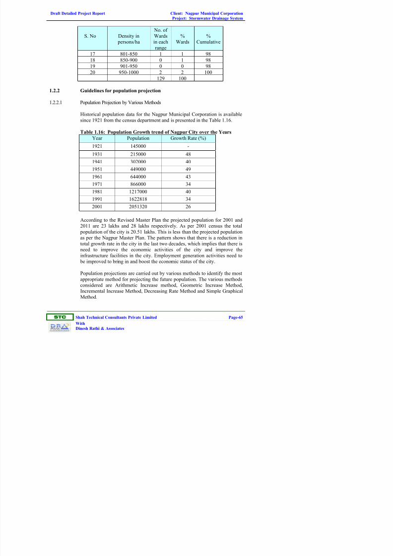
Draft Detailed Project Report Client: Nagpur Municipal Corporation
Project: Stormwater Drainage System
ST
Shah Technical Consultants Private Limited Page-65
With
Dinesh Rathi & Associates
S. No Density in
persons/ha
No. of
Wards
in each
range
%
Wards
%
Cumulative
17 801-850 1 1 98
18 850-900 0 1 98
19 901-950 0 0 98
20 950-1000 2 2 100
129 100
1.2.2 Guidelines for population projection
1.2.2.1 Population Projection by Various Methods
Historical population data for the Nagpur Municipal Corporation is available
since 1921 from the census department and is presented in the Table 1.16.
Table 1.16: Population Growth trend of Nagpur City over the Years
Year Population Growth Rate (%)
1921 145000 -
1931 215000 48
1941 302000 40
1951 449000 49
1961 644000 43
1971 866000 34
1981 1217000 40
1991 1622818 34
2001 2051320 26
According to the Revised Master Plan the projected population for 2001 and
2011 are 23 lakhs and 28 lakhs respectively. As per 2001 census the total
population of the city is 20.51 lakhs. This is less than the projected population
as per the Nagpur Master Plan. The pattern shows that there is a reduction in
total growth rate in the city in the last two decades, which implies that there is
need to improve the economic activities of the city and improve the
infrastructure facilities in the city. Employment generation activities need to
be improved to bring in and boost the economic status of the city.
Population projections are carried out by various methods to identify the most
appropriate method for projecting the future population. The various methods
considered are Arithmetic Increase method, Geometric Increase Method,
Incremental Increase Method, Decreasing Rate Method and Simple Graphical
Method.

Draft Detailed Project Report Client: Nagpur Municipal Corporation
Project: Stormwater Drainage System
ST
Shah Technical Consultants Private Limited Page-66
With
Dinesh Rathi & Associates
1.2.2.2 Arithmetic Increase method
This method is based upon the assumption that the population is increasing at
a constant rate, i.e. the rate of change of population with time is constant.
From the population data for the last 4 to 5 decades, the average increase per
decade is calculated which is then used as the design rate of increase for
calculating the design population. This method is of limited value and may be
useful for smaller design periods for old and very large cities with no
industries and which have practically reached their maximum development.
For developing areas, which develop faster than the past, this method is likely
to give low results.
1.2.2.3 Geometric Increase Method
In this method, it is assumed that the percentage increase in population from
decade remains constant. Therefore, the average value of the percentage
increase is calculated and the future populations are calculated at this rate. For
a young city, which at present is expanding at fasted rate, this method may
give very high results and is useful for old developed cities.
1.2.2.4 Incremental Increase Method
In this method the average increase per decade is found out. The average
incremental increase for each decade is also found out. The future population
is calculated from the average increase and average incremental increase of
population. This method is a combination of the above two methods and
therefore gives the advantages of both and hence gives satisfactory results.
1.2.2.5 Decreasing Rate Method
Rate of increase in population goes on reducing as the cities reach towards
saturation. A method which makes use of the decrease in the percentage
increase is many a times used and gives quite rational increase, which is then
subtracted from the latest percentage increase for each successive decades.
1.2.2.6 Simple Graphical Method
In this method a graph is plotted from the available data, between time and
population. The curve is then smoothly extended up to the desired year. This
method however gives approximate results as the extension of the curve is
done only by the intelligence of the designer.
The population has been forecasted using census data from 1921 to 1991.
Table 1.17 shows the projected population figures by using various methods
for the year 2001. The projected population for the year 2001 is compared
with the actual population. It is noted from the table that the simple graphical
method gives the least percentage of error.

Draft Detailed Project Report Client: Nagpur Municipal Corporation
Project: Stormwater Drainage System
ST
Shah Technical Consultants Private Limited Page-67
With
Dinesh Rathi & Associates
Table 1.17: Population Projections for the year 2001 by various Methods
S.
No.
Method Projected Actual Error
1 Arithmetic Increase Method 1833935 2051320 11%
2 Geometric Increase Method 2293263 2051320 -12%
3 Incremental Increase Method 1889905 2051320 8%
4 Decreasing Rate Method 2252881 2051320 -10%
5 Simple Graphical Method 2038209 2051320 1%
The population is projected for the year 2011, 2021 and 2031 by using all the
methods. Table 1.18 shows the population projected by various methods.
Table 1.18: Population Projections by Various Methods
S.
No.
Method 2011 2021 2031
1 Arithmetic Increase Method 2289610 2527900 2766190
2 Geometric Increase Method 2860566 3989060 5562745
3 Incremental Increase Method 2340825 2630329 2919834
4 Decreasing Rate Method 2796474 3812309 5197153
5 Simple Graphical Method 2531428 3082239 3690642
Simple Graphical method, though gives least error does not take into
consideration major employment generation activities such as MIHAN which
is expected to start functioning in full swing by 2015 (see section 2-1-5). Also
in the last few years there has been a concentrated effort to improve the basic
infrastructure facilities in Nagpur City and in this connection major road
network has been widened and other basic infrastructure facilities have been
improved. The development of MIHAN in turn will lead to development of
allied economic activities in the city. With these developments it is assumed
that the population growth rate will take an upward trend after 2011. The
growth rate of the latest decade has been assumed (same growth rate between
1991 and 2001) for 2001-2011. This is based on the assumption that the
growth rate will stabilise in this decade due to the proposed development
schemes in and around the city, many of which will be in implementation stage
or in operation, towards end of the decade.
Due to induced developments like MIHAN, Boeing MRO facility, Improved
Public Transport System and industrial developments at Butibori, Kamptee
and Hingna in the region outside the city, it is expected that the city would
experience a higher growth rate in population after 2011. To arrive at a
realistic projection of population, consultants have studied the earlier growth
trends of the city and the trends in other Indian cities of comparable sizes and
characteristics, like Pune, Hyderabad and Bangalore, which had experienced
high population growth rates due to induced developments. Based on the
above analysis, Consultants have estimated a growth rate of 36.8% for the
decade 2011-2021.

Draft Detailed Project Report Client: Nagpur Municipal Corporation
Project: Stormwater Drainage System
ST
Shah Technical Consultants Private Limited Page-68
With
Dinesh Rathi & Associates
Most of these development projects will be either complete or in the advanced
stages of completion by the year 2021. Therefore, for the decade 2021-2031, agrowth rate of 31.7% has been projected with the assumption that the
population growth would stabilize in the later decades once the development
activities are completed. The total population has been calculated using these
growth rates. Table 1.19 gives the Population projections for the Nagpur city
Considering Higher Growth Rate.
Table 1.19: Population Projections for Nagpur City considering Higher
Growth Rate
Project PopulationS.
No.
Method of Projection
2011 2026 2041
1 Arithmetical Increase Method 2377563 2749658 3121752
2 Incremental Increase Method 2440063 3023095 3746752
3 Geometrical Progression Method 2915711 4671376 7484197
4 Exponential Method 2830000 5000000 8200000
5 Geometrical Method based on
Annual growth rate based on past
growth trend as adopted in Water
supply project and Master plan /
CDP
2830000 4225780 6275531
The distribution of population among the zones were made taking following
parameters into account. Due weightage is given to each parameter for
arriving the distribution.
• Density of population
• Landuse
• Accessibility
• Special reasons (such as topography, availability of infrastructure etc.)
1.3 List of various Projects Proposed for the Sector in the City Development
Plan (CDP) by NMC and confirmation of how this project is aligned with
stated CDP priorities
S.
No.
Sector Cost
(in Rs. Cr.)
1. Water Supply
Pench IV 422
Leak detection 3
Energy and water audit reports 50
Strengthening of water supply system 115
Sub Total 590.31
2. Sewerage & Sanitation
North Zone 130
Central Zone 239
South Zone 147

Draft Detailed Project Report Client: Nagpur Municipal Corporation
Project: Stormwater Drainage System
ST
Shah Technical Consultants Private Limited Page-69
With
Dinesh Rathi & Associates
S.
No.
Sector Cost
(in Rs. Cr.)
Water recycling and reuse 250
Sub Total 515.00
3. Roads
Outer ring road 6 lane highway 650
Seven ROB’s within the city 128
Ten flyovers 100
Road widening and improvement works 200
Bridges over rivers 8
Sub Total 1085.60
4. Drains
Drainage along roads 45
Nallah canalization 56
Strengthening existing nallahs 45
Rejuvenation of rivers 50
Lake rejuvenation 50
Sub total 245.50
5. Solid Waster Management
Sanitary landfill 25
Bin free city 25
Sub Total 50
6. Urban Poor and Slums
NIT (EWS/LIG Housing) 125
MHADA 42
SRA 1350
Urban poor amenities 75
Sub Total 1550.00
7. Public Transport and Traffic Management
Traffic management 50
Maharashtra Roadways Transport Services 1500
Sub Total 1550
8. Others
Destitute homes 1
Marriage halls 5
Night shelters 4
Public toilets 5
Sub Total 15
Grand total 5894
City Investment – Rs.5894 Crore
1.4 List of other capital expenditure project supported by other schemes for
the sector
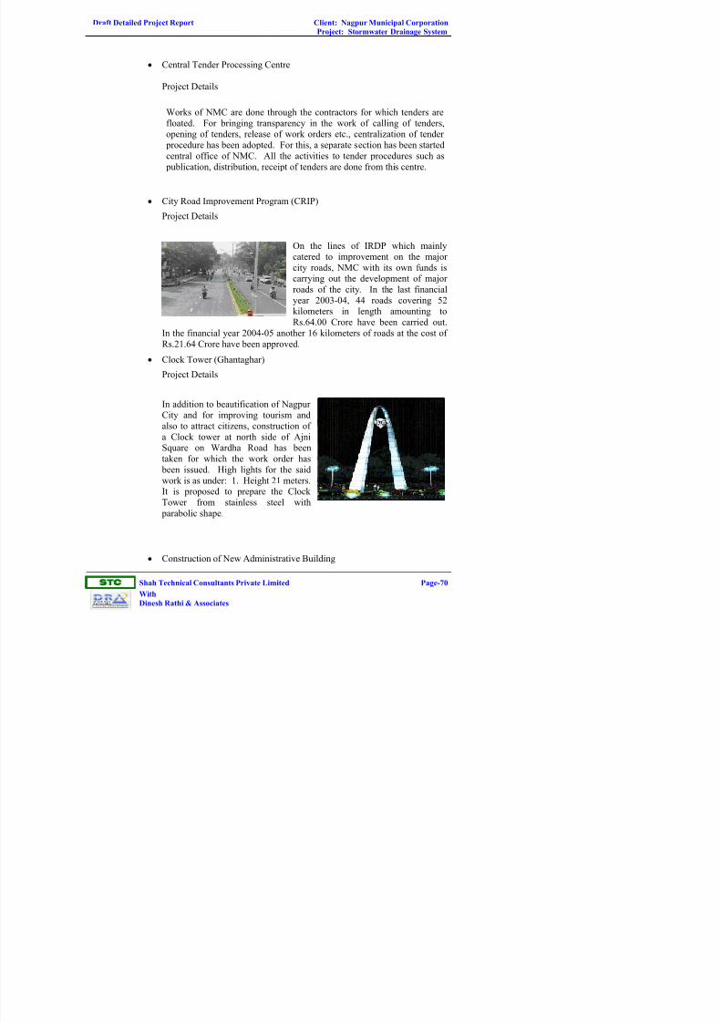
Draft Detailed Project Report Client: Nagpur Municipal Corporation
Project: Stormwater Drainage System
ST
Shah Technical Consultants Private Limited Page-70
With
Dinesh Rathi & Associates
• Central Tender Processing Centre
Project Details
Works of NMC are done through the contractors for which tenders are
floated. For bringing transparency in the work of calling of tenders,
opening of tenders, release of work orders etc., centralization of tender
procedure has been adopted. For this, a separate section has been started
central office of NMC. All the activities to tender procedures such as
publication, distribution, receipt of tenders are done from this centre.
• City Road Improvement Program (CRIP)
Project Details
On the lines of IRDP which mainly
catered to improvement on the major
city roads, NMC with its own funds is
carrying out the development of major
roads of the city. In the last financial
year 2003-04, 44 roads covering 52
kilometers in length amounting to
Rs.64.00 Crore have been carried out.
In the financial year 2004-05 another 16 kilometers of roads at the cost of
Rs.21.64 Crore have been approved.
• Clock Tower (Ghantaghar)
Project Details
In addition to beautification of Nagpur
City and for improving tourism and
also to attract citizens, construction of
a Clock tower at north side of Ajni
Square on Wardha Road has been
taken for which the work order has
been issued. High lights for the said
work is as under: 1. Height 21 meters.
It is proposed to prepare the Clock
Tower from stainless steel with
parabolic shape.
• Construction of New Administrative Building

Draft Detailed Project Report Client: Nagpur Municipal Corporation
Project: Stormwater Drainage System
ST
Shah Technical Consultants Private Limited Page-71
With
Dinesh Rathi & Associates
Project Details
NMC came into existence in
the year 1951 and considering
the city’s expansion and
growing needs, staff of the
NMC have also been
increased but NMC’s
administrative work is still
being carried on in the
existing building which are
located in the different parts
of the city. Various important departments of NMC are situated in
different localities causing inconvenience to the citizens. To solve this
problem, NMC has started the work of construction of new Administrative
Building.
• Development of Octroi Check Posts
Project Details
With the help of 32 octroi check posts, the Octroi Department of NMC is
doing the work of octroi collection and prevention of octroi evasion. i)
In order to modernize the Octroi Nakas, the NMC has passed the
resolution to spend Rs.1.5 Crore each on Hingna Road Naka, Amravati
Road Naka and Wardha Road Naka. ii) Sanction has been granted for
the development plan of these octroi check posts and further process is in
progress.
• Flyover in front of Railway Station
Project Details
As an addition to the city development, a project of construction of
Flyover with shopping complex as pass anger facility centre is
undertaken. For this project an expenditure of Rs.16.23 crores is
estimated. Main characteristics of Flyover
• Improvement of Burning Ghats
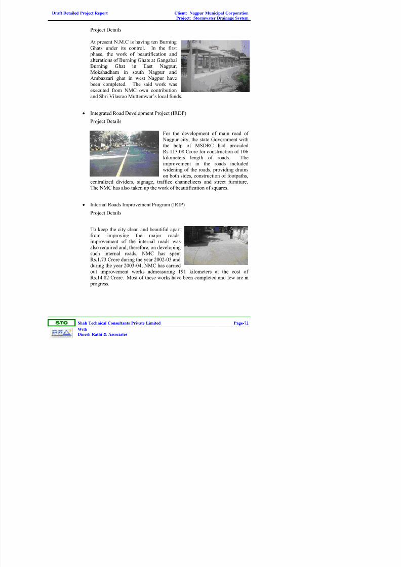
Draft Detailed Project Report Client: Nagpur Municipal Corporation
Project: Stormwater Drainage System
ST
Shah Technical Consultants Private Limited Page-72
With
Dinesh Rathi & Associates
Project Details
At present N.M.C is having ten Burning
Ghats under its control. In the first
phase, the work of beautification and
alterations of Burning Ghats at Gangabai
Burning Ghat in East Nagpur,
Mokshadham in south Nagpur and
Ambazzari ghat in west Nagpur have
been completed. The said work was
executed from NMC own contribution
and Shri Vilasrao Muttemwar’s local funds.
• Integrated Road Development Project (IRDP)
Project Details
For the development of main road of
Nagpur city, the state Government with
the help of MSDRC had provided
Rs.113.08 Crore for construction of 106
kilometers length of roads. The
improvement in the roads included
widening of the roads, providing drains
on both sides, construction of footpaths,
centralized dividers, signage, traffice channelizers and street furniture.
The NMC has also taken up the work of beautification of squares.
• Internal Roads Improvement Program (IRIP)
Project Details
To keep the city clean and beautiful apart
from improving the major roads,
improvement of the internal roads was
also required and, therefore, on developing
such internal roads, NMC has spent
Rs.1.73 Crore during the year 2002-03 and
during the year 2003-04, NMC has carried
out improvement works admeasuring 191 kilometers at the cost of
Rs.14.82 Crore. Most of these works have been completed and few are in
progress.

Draft Detailed Project Report Client: Nagpur Municipal Corporation
Project: Stormwater Drainage System
ST
Shah Technical Consultants Private Limited Page-73
With
Dinesh Rathi & Associates
• Mahatma Fuley Vegetable Market Complex
Project Details
At Mahatma Fuley Vegetable Market sanction has accorded for
construction of vegetable market with Business Complex. In this scheme
preference will be given to license holders vegetable vendors. The
allotment will be on first cum first serve basis by taking advance deposit
for a period of thirty years lease.
• New Centers of Fire Brigade Department
Project Details
NMC is trying its best to provide sufficient Fire Bridage Stations in Nagpur City considering its population. At present six Fire Bridage
Stations are working as follows: 1. Central Fire Bridage Station : West
Nagpur, 2. Panchpaoli Fire Bridage Station : North Nagpur, 3.
Lakadganj Fire Bridage Station : East Nagpur, 4. Sakkardara Fire
Bridage Station : East Nagpur, 5. Ganjipeth Fire Bridage Station :
Central Nagpur, Fire Bridage Station : South Nagpur.
• Scientific efforts to be taken for disposal solid waste (Construction of
Sanitary Land Fill Site)
Project Details
Since last so many years cities
sold waste is being dumped at
Bhandewadi dumping yard and
that too without following the
scientific method causing
ground water and air pollution.
The following measures are
proposed to be undertaken to
change the existing scenario.
1.5 Existing Tariff & Cost Recovery
As far as SWD is concerned and it is not possible to levy separate charges for
this and the expenses to be incurred from general capital works grant and
revenue grant. In case of new developments, development charges can be
levied from the developer or alternatively the developer can be asked to
develop the drains in their development area alongwith roads as the care may
be and handed over to corporator for future maintenance.

Draft Detailed Project Report Client: Nagpur Municipal Corporation
Project: Stormwater Drainage System
ST
Shah Technical Consultants Private Limited Page-74
With
Dinesh Rathi & Associates
1.6 Existing areas of Private Sector / Community Participation in the Sector
Design, construction and project management are carried out through private
sector participation. O & M services can be arranged through departmental,
Private Sectors / Community Participation as per needs and areas of activity.
1.7 Any other qualitative information
Public Awareness and Public Participation
The programme for improvement of SWD system can succeed only if there is
public awareness and participation. The public at large should know about the
project and also the benefits they are going to derive from the project. They
shall be also aware about the cost implication and there should be
preparedness from there side. If the communities are effectively involved in
all stages of the project cycle from conceptualation, to preparation, to
finalization, to implementation and finally O&M, issues involved in the
conservation of water body need to be identified and the programme will need
to focus on them. The objectives of the awareness plan will be determined by
the issues identified. Special campaigns and publicity shall be made to make
the people aware of the consequences of the littering of drains with plastic.
The general public shall be prevented from using the open drains as public
toilets. These programmes can be undertaken or entrusted to NGO’s and socialactivists in the field.
This progrmames will also help to minimize the negative social impacts.
These programmes will also educate the public from the adverse effects of
stormwater pollution / river pollution, and encourage them to practice to abete
the pollution.

Draft Detailed Project Report Client: Nagpur Municipal Corporation
Project: Stormwater Drainage System
ST
Shah Technical Consultants Private Limited Page-75
With
Dinesh Rathi & Associates
CHAPTER-2.0
PROJECT DEFINITION, CONCEPT AND SCOPE
Key issue – Objective of the study
The main objective of the study is to prepare a comprehensive proposal, which
will be technically and financially viable for the implementation of stormwater
drainage system and rejuvenation of lakes and rivers in Nagpur City.
Description of Project Area
Nagpur is situated in the middle of India at 21° 06' N latitude and 79º 03' E
longitude and a mean altitude of 310 meters above sea level. Nagpur is
named after the Nag river which originates from Ambazari Lake located at the
west part of Nagpur city and drains into Kanhan River in south east and the
length of river in city boundary is 17 kms.
Another river originates from Gorewada lake at north west and flows from
west to east in the northern part of Nagpur called Pioli River having a length
of 17 km also joins to Nag river and drains to Kanhan River.
There is one more river named Pora River originates from Sonegaon, western
part of the city and flows from west to south east outside the southern part of
the city and draining into Kanhan River.
There are many major Nallahs and minor Nallahs discharging stormwater into
these rivers. Oranges are grown extensively in and around Nagpur and there is
also an Orange market (Santra Mandi) in Nagpur and therefore city is also
known as Orange city.
2.1 Land
Additional land requirement is minimum for the nallahs and rivers as they are
existing and only improvements are required. It may be possible that some of
the areas of natural waters can be included and removal of encroachment may
be necessary from the existing map. It is not possible to identify the exact area
of land to be acquired from the private owners unless otherwise a detailed
survey of the area alongwith the revenue land record staff is carried out.
Major portion of the land required is under the possession of the ULB as the
drain to be constructed is on the road side.

Draft Detailed Project Report Client: Nagpur Municipal Corporation
Project: Stormwater Drainage System
ST
Shah Technical Consultants Private Limited Page-76
With
Dinesh Rathi & Associates
2.2 Physical Infrastructure Components
2.2.1 Data Collection
As part of planning and location studies, collection of all available information
pertaining to the project is vital for bringing out a proper design of the project
and for its successful completion. Several categories of data have been
obtained and evaluated including;
• Physical characteristics of drainage basin
• Maps and topographic data including Nallah survey, river basin survey and
cross sections
• Runoff quantity data (hydrologic and precipitation data)
• Channel and floodplain delineations and related studies
• Flood history and problem inventory
• Existing stormwater drainage system details
• Development of alternative plan concepts
• Hydrologic and hydraulic analysis of alternative concepts
The data that have been collected for the present project are given in Table
No. 2.1 below.
Table 2.1: Inventory Data / Information
S. No. Data Description Source
1. Plan showing the project area NMC
2. Toposheets Survey of India
3. Plan showing ward boundaries NMC
4. Plan showing roads NMC
5. Nagpur city development plan
showing existing and proposed land
use
NMC
6. Existing drainage system details NMC, Field survey
7. Layout maps/ cluster maps of layout
regularized by NIT under
GUNTHEWARI VIKAS ACT 2001
(Regularization, upgradation and
development)
NIT
8. Rainfall data from year 1969-2000
(Hydrologic data)
Pune Meteorological Deptt.
9. Flood data Interviews with residents,
local officials, past flood
records
10. High water information (High flood
levels)
Interviews with residents

Draft Detailed Project Report Client: Nagpur Municipal Corporation
Project: Stormwater Drainage System
ST
Shah Technical Consultants Private Limited Page-77
With
Dinesh Rathi & Associates
2.2.2 Topographical Survey, Nallah and River Basin Survey, Geo-Technical
Investigations
Stormwater drainage system is affected by gravity and therefore accurate
topographic survey of the project area based on street levels is of prime
importance to the design of the system and its subsequent efficient
performance. A topographic survey has been carried out for the unsewered
area of the city and a contour map has been prepared for the NMC area taking
into account the new street levels as well as street levels available for the areas
sewered. All new roads have been incorporated into the city map.
2.2.3 Nallah and River Survey
Since final disposal of storm will be in river basins through minor and major
Nallahs, levels of all disposal points, chainages are very important, hence
survey of Nallahs and river basins have been carried out, L-Sections and cross
sections have been prepared. Surveyed length of major nallahs, minor nallahs
in North Zone and surveyed length of Pioli and Nag river is given in Table
2.2(a), 2.2(b) and 2.2(c) respectively.
Table 2.2 (a): Surveyed Length of Major Nallah in North Zone
S. No Nomenclature / Name of
Nallah
Length of Nallah (m)
1 L1 2702
2 L2 (Ved Nagar Nallah) 3210
3 L3 (Nara Nallah) 3545
4 L4 10160
5 R1 500
6 R2 (Bor Nallah) 6225
7 R3 (Chamar Nallah) 5610
8 R4 3080
9 R5 180
10 R6 710
11 R7 (Taj Nagar Nallah) 2270
12 R8 (Vishwas Nagar Nallah) 570
13 R9 1830
14 R10 (Shantinagar Nallah) 7710

Draft Detailed Project Report Client: Nagpur Municipal Corporation
Project: Stormwater Drainage System
ST
Shah Technical Consultants Private Limited Page-78
With
Dinesh Rathi & Associates
Table 2.2 (b): Surveyed Length of Minor Nallah in North Zone
S. No Nomenclature /
Name of Nallah
Length of Nallah (m)
1 L2/R1 2580
2 L3/L1 1445
3 L3/L2 720
4 L4/R1 1465
5 R2/L1 1520
6 R2/L2 1580
7 R2/L3 1930
8 R2/L4 980
9 R2/L5 450
10 R2/L7 125
11 R2/R1 1050
12 R2/R2 580
13 R2/R3 380
14 R3/L1 1440
15 R3/L2 810
16 R3/R1 4375
17 R3/R2 1775
18 R3/R3 1430
19 R3/R4 330
20 R10/L1 230
21 R10/L2 580
22 R10/L3 1190
23 R10/L4 230
24 R10/R1 380
25 R10/R2 50
Table 2.2 (c): Surveyed Length of River
S. No Name of River Length of River (m)
1 Pioli River 17815
2 Nag River 16732
3 Pora River 13383
Total length of road survey carried out is 800 kms.

Draft Detailed Project Report Client: Nagpur Municipal Corporation
Project: Stormwater Drainage System
ST
Shah Technical Consultants Private Limited Page-79
With
Dinesh Rathi & Associates
2.2.4 Wastewater Sampling and Analysis
Quality Analysis of household sewage discharging into the street sewers and
of the receiving water bodies at major wastewater outfalls has been carried
out. Samples were collected from the Nallahs and other natural streams
running through NMC. Two important water courses in the NMC are the Nag
river and the Pioli river. Samples were collected from these streams before
and after the entry of polluting discharges. Samples from six Nallahs were
also collected and analysed. The samples were tested for pH, BOD, COD,
TSS, TDS, N, P, K etc. to assess level of contamination. Analysis results for
samples from street sewers, lakes, receiving streams within NMC has been
given in detail in the Draft Master Plan Report for sewerage system submitted
to NMC in January, 2008.
Analysis result from samples from receiving streams is reproduced in this
report in Table 2.3.
Result shows that the streams are highly polluted because of the discharge of
sewage into it.

Draft Detailed Project Report Client: Nagpur Municipal Corporation
Project: Stormwater Drainage System
ST
Shah Technical Consultants Private Limited Page-80
With
Dinesh Rathi & Associates
Table 2.3: Analysis Results for Samples from City Nallah
Nag River Pioli RiverS.
No.Parameters
Start Middle End Start Middle End
Trimurt
hi Nagar
Nallah
Wardha
Road
Nallah
Nallah
near
Besa
Village
Nallah
near
Maharaj
Bagh
Nallah
near
Narenha
Nagar
Nallah
near
Manesoada
Chowk
1. Date of
Sampling
21.8.07 21.8.07 21.8.07 17.8.07 17.8.07 17.8.07 21.8.7 21.8.07 21.8.07 21.8.07 21.8.07 21.8.07
2. Sampling
Location
At
bridge
near
Waste
Weir
Near
Yashwant
Stadium
Near
Pardi
Near
Gorewada
Tank
c/s of
Nagpur
Sonoor
Road
Kamptee
Road
Old.
O.F.
Rly.
Bridge
Road
Bridge
NH-7
Karvey
Nagar
- - - -
3. PH 7.9 7.3 7.7 7.8 7.3 7.4 7.6 7.4 7.3 7.4 7.4 7.5
4. SS, mg/L 10 35 10 26 46 58 20 83 100 52 190 170
5. BOD
mg/L
1.5 30.0 22.0 2.0 2.0 34.0 1.5 38.0 34.0 25.0 40.0 44
6. COD
mg/L
6.0 128.0 90.0 7.0 7.0 128.0 8.0 170.0 160.0 140.0 170.0 188.0
7. TDS,
mg/L
236 293 400 240 364 442 786 400 430 353 410 640

Draft Detailed Project Report Client: Nagpur Municipal Corporation
Project: Stormwater Drainage System
ST
Shah Technical Consultants Private Limited Page-81
With
Dinesh Rathi & Associates
2.2.5 Geo-Technical Investigation
The geo-technical studies have been conducted in the location between
Sonegoan and Kamptee.
The work of Engineering Survey and Soil Investigation was carried out by
subsurface exploration investigations with 12 drill holes have been done to
ascertain geo-technical status. All the holes were drilled using double core
barrel Nx size, ranging in depth 7 m to 20 m.
The area of Nagpur city is occupied by the following rock types viz.
Archaeans, Gondwana, Lametas, Deccan traps and alluvium of recent age. The
crystalline rocks are encountered in the eastern part of the city, which are
gneisses, schists and granites. The Gondwana formations are represented by
Sandstones and shales and coal bearing horizons and are exposed on the
Northern part of the city in a limited area. The lametas occur as narrow fringe
from north to central part and further southwest to southeast of Nagpur city
area consisting of sand stone variegated clays and cherty lime stones. Deccan
trap basalt flows are met with in the western and southern parts separated by
layer of “Red Bole” beds and identified sequence of different Lava flows in
the major part of the Nagpur city. The alluvium of recent age comprises of
sand, silt clay kankar and its admixture in small patches near Pioli river.
2.2.6 Hydrologic and Climate Status
The ground water regime has undergone changes in the urban hydrology. The
ground water occurs under both pheratic and semi confing to confing
conditions. The ground water level during the summer months (pre-monsoon)
varies 4.00 m to 16.25 m below ground level.
Deeper water levels more than 9 m have been recorded in the Northern, North-
eastern and Eastern part of the city. In the central and southern parts of the
city water level is less than 9 m below ground level. Post monsoons period
depth of water levels ranged between 0.55 m and 14.85 m below ground
levels. Generally the water levels ranged from 0.2 m to 9.12 m in the area.
2.2.7 Hydrologic analysis for drainage facility design
The analysis of the peak runoff, volume of runoff and the time distribution of
flow is fundamental to the design of drainage facility. Many hydrologic
methods are available for conversion of precipitation into runoff. The widely
used method is rational method. We have adopted the same method for
determining the peak runoff for a specified storm return period. The equation
used is:

Draft Detailed Project Report Client: Nagpur Municipal Corporation
Project: Stormwater Drainage System
ST
Shah Technical Consultants Private Limited Page-82
With
Dinesh Rathi & Associates
Q = 10 CiA . . . . . . . . . . . . . . (1)
Where Q = Peak runoff in m3/hr
C = Runoff coefficient
i = rainfall intensity in mm/hr
A = the Catchment area in ha
2.2.8 Steps followed for the Determination of Storm Runoff for the Project
Area
• Gather background information such as topographic mapping, land use
data, precipitation information etc.
• Decide on the appropriate return period, storm frequency and
concentration time
• Find the maximum rainfall intensity for those condition (i, mm/hr) using
IDF curves
• Estimate the runoff coefficient for the catchments(C) by delineating
drainage area to determine the varies land characteristics
• Calculate the catchment area served by that drain (A in ha)
• From i, A and C, calculate the peak flow i.e. maximum quantity of
stormwater to be drained per hour
This details are discussed as follows.
2.2.9 Return Period and Storm Frequency
The return period and frequency are statistical descriptions of the severity of a
storm event. The return period is the expected length of time between two
rainfall events that exceed a specific magnitude. Frequency is the inverse of
the return period.
As mentioned in CPHEEO manual ( page 41, para 3.3.1.2 ) the return period
is adopted as 0.5,1 and 2 years depending on the importance of the area to be
drained. Table 2.4 shows ward number, ward name and return period (storm
frequency) proposed to be adopted for the design purpose.
For open channel/ nallahs, the storm frequency considered is once in 2 years
and for river channel once in 25 years.

Draft Detailed Project Report Client: Nagpur Municipal Corporation
Project: Stormwater Drainage System
ST
Shah Technical Consultants Private Limited Page-83
With
Dinesh Rathi & Associates
2.2.10 Time of Concentration (tc)
The time of concentration tc is the time required for water to flow from the
hydraulically most remote point of the drainage area to the point of discharge.
With the rational method, the duration of a rainfall event is set equal to the
time of concentration and it is used to estimate the average rainfall intensity[from the intensity-duration-frequency curves (IDF)] for a selected return
period.
The time of concentration to any point in a storm drainage system is the sum
of the inlet time and the time of flow t f in the upstream drain connected to the
catchment, that is
tc = ti + tf
Where the flow time is
tf = L/V
Where; L = Length of drain in m.
V = Avg. velocity in m/s. in the drain.
Inlet time concentration is worked out using kirpich equation for Nallah basin
which is as follows
0.77 0.3850.01947ct L S −= ………. (2)
Where tc = time of concentration, minutes
L=maximum length of travel of water in basin, meter
S= slope of catchment

Draft Detailed Project Report Client: Nagpur Municipal Corporation
Project: Stormwater Drainage System
ST
Shah Technical Consultants Private Limited Page-84
With
Dinesh Rathi & Associates
Table 2.4: Ward Number, Ward Name and Return Storm Frequency
Reference: - Manual on Sewerage and Sewage Treatment, CPHEEO (Page
No. 41. Para 3.3.1.2)
Ward No. Ward NameStorm
Frequency
Rainfall areas
7, 8, 9, 10, 11, 12,
13, 14, 15, 16, 17,
51
Bhandewadi,Wathoda,Dighori,Mhalgi
Ngr,Manewada, Gogi Ngr, Narendra Ngr,
Sonegaon, Jaitala, Ambazari,
Vishvashvaraiya, Telenkhedi
Twice a
year
Peripheral
Area
1, 2, 3, 4, 5, 6, 18,
19, 20, 21,22, 23,
24, 25, 26, 27, 28,
29, 30, 32, 33, 34,
35, 36, 37, 38, 39,
40, 41, 42, 43, 45,
46, 47, 48, 49, 50,
52, 54, 55, 56,57,
59, 60, 61, 62, 66,
67, 68, 69, 71, 73,
74, 75, 76, 77, 78,
79, 81, 84, 86, 90,
91, 92, 93, 94, 95,
96, 97,98, 99, 100,
101, 106, 111,
112, 113, 114,
116, 117, 120,
122, 124, 125.
Gorewada,Nara,Nari,YashodhraNgr,
Kalamna, Pardi, Borgaon, Police Line
Takali, Mankapur, Chhawani, Jaripatka,
Nagsen Ngr, Sidhartha Ngr, Mahendra
Ngr, Rani Durgawati Ngr, Navi
Mangalwari, Prem Ngr, Shanti Ngr, Dipti
Signal, Vardhaman Ngr, Hiwari, Kumbhar
Toli, Darshan Colony, Nandanvan, Harpur,
Sakkardara, Bidipeth, New Subhedar,
Ayodhya Ngr , Gyaneshwar Ngr, Parvati
Ngr, Chunabhati, Sai Mandir, Khamla,
Swavalambi Ngr, Subhash Ngr, Gopal Ngr,
Hill Top, Surendra Ngr, Ravi Ngr, Hajari
Pahad, Seminary Hills, Nai Basti, Mekosa
Bagh, Indora, Choukse colony, Naik Talao,
Khairipura, Bastarwari, Subash
Chandrabose, Lakhadganj, Shiv Ngr, Om
Ngr, Raghugi Ngr, Vishvakarma Ngr,
Chandramani Ngr, Kausalya Ngr, T. B.
Ward, Pratap Ngr, Shivaji Ngr, Civil Lines,
Lakshari Bagh, Balabha Peth, Tanda Peth,
Lendi Talao, Bhagwan Mahavir,
Chinteswar Ngr, Juni Mangalwari,
Nawabpura, Juni shukarwari, Reshimbagh,
Somwar Peth, Sangam,Bhan Keda, Barase
Nagar, Jaganath Nagar, Maskasath,
Ayachit Nagar, Killa, Chandan Ngr,
Ganeshpeth, Momin Pura, Timki
Once a year
Central and
comparatively
high priced
areas
31, 44, 53, 58, 63,
64, 65, 70, 72, 80,
82, 83, 85, 87, 88,
89, 102, 103, 104,
105, 107, 108,
109, 110, 115,
118, 119, 121,
123, 126, 127,
128, 129
Minimata Ngr, Ajni, Ram Ngr, Sadar,
Gurunanak, Vaishalinagar, Panchasilnagar,
Harihar Mandir, Bagadganj, Jail Ward,
Diksha Bhumi, Ramdaspeth, Dharampeth,
Gaddigodam, Moti Bagh, Nawa Naksha,
Medical College, Rambagh, Shaniwari,
Dhantoli, Sitabudi, Khalashi Line,
Boriapura, Saifi Nagar, Mahathma Gandhi,
Nagar Bhawan, Siraspeth, Model Mill,
Bajeria, Gandhi Bagh, Mahal, Ganji Peth,
Hansa Puri
Once in 2
years
Commercial
and high
priced areas

Draft Detailed Project Report Client: Nagpur Municipal Corporation
Project: Stormwater Drainage System
ST
Shah Technical Consultants Private Limited Page-85
With
Dinesh Rathi & Associates
2.2.11 Rainfall Intensity : Detailed Study and Analysis of Rainfall data of
the Project Area
The available data acquired from Pune Meteorological department includes
24-hour Rainfall data basis from 1969-2000 for the Nagpur city. These data
sets are used to carryout frequency analyses to determine the magnitude of
peak flows of known return periods to achieve an optimized design. The total
Yearly rainfall is plotted in the Figure 2.1.
0
200
400
600
800
1000
1200
1400
1600
1 9 6 8
1 9 7 0
1 9 7 2
1 9 7 4
1 9 7 6
1 9 7 8
1 9 8 0
1 9 8 2
1 9 8 4
1 9 8 6
1 9 8 8
1 9 9 0
1 9 9 2
1 9 9 4
1 9 9 6
1 9 9 8
2 0 0 0
Years
T o
t a l P r e c
i p i t a t i o n
( m m
)
Figure 2.1: Total Yearly Rainfall in mm during the period 1969-2000
The maximum daily rainfall data is evaluated from the available data. As the
rainfall data for years 1992 and 1997 was missing, these were synthesized
from the mean of preceding and subsequent year’s rainfall data of the
respective years to complete the data set. Subsequently, the intensities for
different return periods and durations are formulated using IDF Curves using
empirical equations and theories of probability. The maximum daily rainfall
during the period 1969-2000 is shown in Table 2.5.

Draft Detailed Project Report Client: Nagpur Municipal Corporation
Project: Stormwater Drainage System
ST
Shah Technical Consultants Private Limited Page-86
With
Dinesh Rathi & Associates
Table 2.5: Maximum Daily Rainfall Recorded During 1969-2000
S. No. YearMax. Daily Rainfall during
year in 'mm'
1 1969 60.5
2 1970 129.2
3 1971 142.1
4 1972 55.6
5 1973 168.9
6 1974 69.8
7 1975 89.1
8 1976 116.5
9 1977 63.3
10 1978 94.4
11 1979 145.4
12 1980 98.2
13 1981 115
14 1982 72.2
15 1983 100.3
16 1984 83.7
17 1985 125.7
18 1986 124.8
19 1987 61.2
20 1988 96.6
21 1989 83.6
22 1990 86.5
23 1991 148.3
24 1992 120.05
25 1993 91.8
26 1994 270.1
27 1995 122.2
28 1996 58.1
29 1997 57.35
30 1998 56.6
31 1999 96.2
32 2000 137
The objective of hydrologic frequency analysis is to interpret a past record of
hydrologic events in terms of future probabilities of occurrence. The
procedure involves selecting a sample in the form of an available data series,

Draft Detailed Project Report Client: Nagpur Municipal Corporation
Project: Stormwater Drainage System
ST
Shah Technical Consultants Private Limited Page-87
With
Dinesh Rathi & Associates
fitting a theoretical probability distribution to the sample, and then making
inferences.
The rainfall Intensity-Duration-Frequency (IDF) relationship is one of the
most commonly used tools in for various engineering projects against floods.
The establishment was done as early as in 1932 (Bernard). Since then, many
sets of relationships have been constructed for several parts of the globe.
There has considerable attention and research on the IDF relationship:
Hershfiled (1961) developed various rainfall contour maps to provide the
design rain depths for various return periods and durations. Bell(1969)
proposed a generalized IDF formula using the one hour, 10 years rainfall
depths; P1 10
, as an index. Chen (1983) further developed a generalized IDF
formula for nay location in the united States using three base rainfall depths:
P1 10
P24 10
P1 100
which describe the geographical variation of rainfall.
Kouthyari and Garde (1992) presented a relationship between rainfall intensity
and P24 2 for India.
Koutsoyiannis et al.(1998) cited that IDF relationship is a mathematical
relationship between the rainfall intensity ‘i,’ the duration ‘d’ and the return
period ‘T’ (or equivalently, the annual frequency of exceedance, typically
referred to as ‘frequency’ only).
Empirical IDF Formulas: The IDF formulas are the empirical equations
representing a relationship among maximum rainfall intensity (as dependant
variable) and other parameters of interest such as rainfall duration and
frequency (as independent variables). There are several commonly used
functions found in the literature of hydrology applications (Chowetal., 1988),
four basic forms of equations used to describe the rainfall intensity duration
relationship are summarized as follows:
Talbot Equationbd
ai
+=
Bernard Equationn
ai
d =
Kimijima Equation n
ai
d b=
+
Sherman Equation( )
n
ai
d b
=+

Draft Detailed Project Report Client: Nagpur Municipal Corporation
Project: Stormwater Drainage System
ST
Shah Technical Consultants Private Limited Page-88
With
Dinesh Rathi & Associates
Where ‘i’ is the rainfall intensity (mm/hour); d is the duration (minutes); a, b
and n are the constant parameters related to the metrological conditions.
These empirical equations show rainfall intensity decreases with increase in
rainfall duration for a given return period. All functions have been widely used
for hydrology practical applications. The least-square method is applied to
determine the parameters of the empirical IDF equations that are used to
represent intensity-duration relationships. The value of parameters in the
rainfall IDF equations were chosen on minimum of Root Mean Square Error
(RMSE) between the IDF relationships produced by the frequency analysis
and simulated by the IDF equation.
From daily maximum rainfall ,corresponding values of 1-hr,2-hr,3-hr,6-hr and
12-hr rainfall values can be obtained using Indian Meteorological
Department(IMD) empirical reduction formula(Ramaseshan,1996),given
below:
( )1
3
2 4 2 4t t P P = ………. (3)
Where Pt is required precipitation depth for the duration t-hour in mm, P24 is
daily precipitation in mm and t is the time duration in hours for which
precipitation depth is required in hours.
Generalized IDF formula using evaluated precipitation depth, and based on
return period is used for formulating the intensities.
a) Alternative-I
As per IDF generalized formula
n
ai
d = ………. (4)
ma C T = ………. (5)
Where i – Intensity in mm/hr
T- Return period in Years
C, m, n are regional coefficients
d- Duration in Hours

Draft Detailed Project Report Client: Nagpur Municipal Corporation
Project: Stormwater Drainage System
ST
Shah Technical Consultants Private Limited Page-89
With
Dinesh Rathi & Associates
Methodology
The available data acquired from Pune Meteorological department includes
24-hour Rainfall data basis from 1969-2000 for the Nagpur city. The entire
rainfall data is used to carryout frequency analyses to determine the maximum
intensities for known return periods and various durations.
1. From the available data, the maximum daily rainfall recorded for each
of the year during the period 1969-2000 is tabulated.
2. The hourly maximum rainfall (i.e. 1 hr, 2 hr …. 12 hr) is evaluated
using the IMD (Indian Meteorological Department) reduction formula
as given in equation (3) and presented in Table 2.6.
3. From the evaluated maximum hourly rainfall data, the mean and
standard deviation are evaluated.
Standard Deviation is carried out using the ‘Predefined Function in MS
Excel’ or can be calculated using the formula mentioned below.
( )2
1
1
N
i
i
X
s N
=
−
=−
∑ ………. (6)
Where N = Number of Sample Years
Xi = Maximum Precipitation Depth, mm
= Mean of Maximum Precipitation Depths for N samples
4. The hourly Precipitation depth analysis is carried out for various return
periods using the Probability Distribution Function for EV-1 is given
by equation (7).
d m r P P K s= + ………. (7)
Where, Pm = Mean Precipitation, mm
Pd = Precipitation Depth, mm
K r = frequency factor

Draft Detailed Project Report Client: Nagpur Municipal Corporation
Project: Stormwater Drainage System
ST
Shah Technical Consultants Private Limited Page-90
With
Dinesh Rathi & Associates
And s = Standard Deviation
‘K r ’, the frequency factor is evaluated by using formula mentioned
below as per Gumbel’s Extreme Value (type 1) distribution.
( ( ) )6 {0.5772 ln ln 1 1 }r K T π = − + − − …. (8)
Where T is Return Period in years. The values are tabulated in Table
2.7.
5. Maximum precipitate depths (1 hr, 2 hr …. 12 hr) are converted into
hourly intensities and tabulated in Table 2.8.
6. A graph (Figure 2.2) is plotted using the values of hourly intensities
and duration for different return periods in MS Excel. The values of ‘a’
and ‘n’ (specified in equation 4) for each return period are found out.
7. The values of “a’ obtained from the above equations for various return
periods are plotted against the return periods to evaluate the regional
coefficients ‘c’ and ‘m’ in equation (5). From the Figure 2.3 the value
of C and m are obtained as 34.405 and 0.1985
8. The generalized Intensity-Duration-Frequency equation (4) is
developed by substituting the coefficients evaluated (Figure 2.4)
9. Maximum intensities for various durations and return periods are
evaluated using the above equation (4).
The regional coefficients c,m,n are substituted in equation (4) to obtain
the generalised equation for Nagpur City .
( )
0 .1985
0 .673 4 . 4 0 5
T i
d = ………. (9)
T- Return period in years
d- Duration in hours
i - mm/hr

Draft Detailed Project Report Client: Nagpur Municipal Corporation
Project: Stormwater Drainage System
ST
Shah Technical Consultants Private Limited Page-91
With
Dinesh Rathi & Associates
Using the equation (9) the intensities for various return periods and
durations are evaluated. Intensities are plotted for various return
periods and durations as shown in Figure 2.4.The estimated intensities
(mm/hr) are tabulated in Table 2.9.
Intensity - Duration
y = 38.664x-0.6667
y = 47.034x-0.6667
y = 55.854x-0.6667
y = 66.998x-0.6667
y = 83.472x-0.6667
1.00
10.00
100.00
1 10
Log Duration in Hrs
L o g I n t e n s i t y ( m m / h r )
2-Year
5-year
10-Year
25-Year
100-Year
Figure 2.2: Log Duration Vs Log Intensity for Gumbel’s Extreme
Value (type 1) Distribution

Draft Detailed Project Report Client: Nagpur Municipal Corporation
Project: Stormwater Drainage System
ST
Shah Technical Consultants Private Limited Page-92
With
Dinesh Rathi & Associates
Table 2.6: Maximum Precipitation Depth for 1hr , 2hr….12 hrs Using IMD Reduction Formula
Precipitation Depth , mm
Duration , hoursS.No. Year
Max. DailyRainfall in
'mm'1.00 2.00 3.00 4.00 5.00 6.00 7.00 8.00 9.00 10.00 11.00 12.00
1 1969 60.5 20.97 26.43 30.25 33.29 35.87 38.11 40.12 41.95 43.63 45.19 46.65 48.02
2 1970 129.2 44.79 56.43 64.60 71.10 76.59 81.39 85.68 89.58 93.17 96.50 99.61 102.55
3 1971 142.1 49.26 62.07 71.05 78.20 84.24 89.52 94.24 98.53 102.47 106.13 109.56 112.78
4 1972 55.6 19.28 24.29 27.80 30.60 32.96 35.03 36.87 38.55 40.09 41.53 42.87 44.13
5 1973 168.9 58.55 73.77 84.45 92.95 100.13 106.40 112.01 117.11 121.80 126.15 130.22 134.06
6 1974 69.8 24.20 30.49 34.90 38.41 41.38 43.97 46.29 48.40 50.33 52.13 53.82 55.40
7 1975 89.1 30.89 38.92 44.55 49.03 52.82 56.13 59.09 61.78 64.25 66.55 68.70 70.72
8 1976 116.5 40.39 50.89 58.25 64.11 69.06 73.39 77.26 80.78 84.01 87.01 89.82 92.47
9 1977 63.3 21.94 27.65 31.65 34.84 37.53 39.88 41.98 43.89 45.65 47.28 48.80 50.24
10 1978 94.4 32.73 41.23 47.20 51.95 55.96 59.47 62.60 65.45 68.07 70.51 72.78 74.93
11 1979 145.4 50.41 63.51 72.70 80.02 86.20 91.60 96.43 100.81 104.85 108.60 112.10 115.40
12 1980 98.2 34.04 42.89 49.10 54.04 58.21 61.86 65.12 68.09 70.81 73.35 75.71 77.94
13 1981 115 39.87 50.23 57.50 63.29 68.17 72.45 76.27 79.74 82.93 85.89 88.67 91.28
14 1982 72.2 25.03 31.54 36.10 39.73 42.80 45.48 47.88 50.06 52.07 53.93 55.67 57.31
15 1983 100.3 34.77 43.81 50.15 55.20 59.46 63.19 66.52 69.54 72.33 74.91 77.33 79.61

Draft Detailed Project Report Client: Nagpur Municipal Corporation
Project: Stormwater Drainage System
ST
Shah Technical Consultants Private Limited Page-93
With
Dinesh Rathi & Associates
Precipitation Depth , mm
Duration , hoursS.No. Year
Max. Daily
Rainfall in
'mm'1.00 2.00 3.00 4.00 5.00 6.00 7.00 8.00 9.00 10.00 11.00 12.00
16 1984 83.7 29.02 36.56 41.85 46.06 49.62 52.73 55.51 58.03 60.36 62.52 64.53 66.43
17 1985 125.7 43.58 54.90 62.85 69.18 74.52 79.19 83.36 87.16 90.65 93.89 96.92 99.77
18 1986 124.8 43.27 54.51 62.40 68.68 73.98 78.62 82.76 86.53 90.00 93.21 96.22 99.05
19 1987 61.2 21.22 26.73 30.60 33.68 36.28 38.55 40.59 42.43 44.13 45.71 47.19 48.57
20 1988 96.6 33.49 42.19 48.30 53.16 57.27 60.85 64.06 66.98 69.66 72.15 74.48 76.67
21 1989 83.6 28.98 36.52 41.80 46.01 49.56 52.66 55.44 57.97 60.29 62.44 64.46 66.35
22 1990 86.5 29.99 37.78 43.25 47.60 51.28 54.49 57.36 59.98 62.38 64.61 66.69 68.66
23 1991 148.3 51.41 64.78 74.15 81.61 87.91 93.42 98.35 102.83 106.94 110.77 114.34 117.71
24 1992 120.05 41.62 52.44 60.03 66.07 71.17 75.63 79.61 83.24 86.57 89.67 92.56 95.28
25 1993 91.8 31.83 40.10 45.90 50.52 54.42 57.83 60.88 63.65 66.20 68.57 70.78 72.86
26 1994 270.1 93.64 117.98 135.05 148.64 160.12 170.15 179.12 187.28 194.78 201.74 208.25 214.38
27 1995 122.2 42.36 53.38 61.10 67.25 72.44 76.98 81.04 84.73 88.12 91.27 94.22 96.99
28 1996 58.1 20.14 25.38 29.05 31.97 34.44 36.60 38.53 40.28 41.90 43.39 44.80 46.11
29 1997 57.35 19.88 25.05 28.68 31.56 34.00 36.13 38.03 39.76 41.36 42.83 44.22 45.52
30 1998 56.6 19.62 24.72 28.30 31.15 33.55 35.66 37.54 39.24 40.82 42.27 43.64 44.92
31 1999 96.2 33.35 42.02 48.10 52.94 57.03 60.60 63.80 66.70 69.37 71.85 74.17 76.35

Draft Detailed Project Report Client: Nagpur Municipal Corporation
Project: Stormwater Drainage System
ST
Shah Technical Consultants Private Limited Page-94
With
Dinesh Rathi & Associates
Precipitation Depth , mm
Duration , hoursS.No. Year
Max. Daily
Rainfall in
'mm'1.00 2.00 3.00 4.00 5.00 6.00 7.00 8.00 9.00 10.00 11.00 12.00
32 2000 137 47.50 59.84 68.50 75.39 81.22 86.30 90.86 94.99 98.79 102.33 105.63 108.74
MEAN 36.19 45.59 52.19 57.44 61.88 65.76 69.23 72.38 75.27 77.96 80.48 82.85
STANDARD DEVIATION 15.07 18.99 21.74 23.93 25.78 27.39 28.84 30.15 31.36 32.48 33.53 34.51

Draft Detailed Project Report Client: Nagpur Municipal Corporation
Project: Stormwater Drainage System
ST
Shah Technical Consultants Private Limited Page-95
With
Dinesh Rathi & Associates
Table 2.7: Evaluation of Precipitation Depth
Note: EV –Extreme Value (Type 1 distribution) Frequency Factor
Table 2.8: Evaluation of Rainfall Intensity
Rainfall Intensity , mm/hr
Duration , HoursReturn Period
in Years
1 2 3 4 5 6 7 8 9 10 11 12
2.00 38.66 24.36 18.59 15.34 13.22 11.71 10.57 9.67 8.94 8.33 7.82 7.38
5.00 47.03 29.63 22.61 18.67 16.09 14.24 12.85 11.76 10.87 10.13 9.51 8.97
10.00 55.85 35.19 26.85 22.17 19.10 16.92 15.26 13.96 12.91 12.03 11.29 10.66
25.00 67.00 42.21 32.21 26.59 22.91 20.29 18.31 16.75 15.48 14.43 13.55 12.78
100.00 83.47 52.58 40.13 33.13 28.55 25.28 22.81 20.87 19.29 17.98 16.88 15.93
Precipitation depth , 'mm'
Duration , Hours
ReturnPeriod
in Years
Frequencyfactor forEV(Type1
distribution)
ReturnPeriod
1 2 3 4 5 6 7 8 9 10 11 12
2.00 0.16 2.00 38.66 48.71 55.76 61.38 66.12 70.26 73.96 77.33 80.43 83.30 85.99 88.52
5.00 0.72 5.00 47.03 59.26 67.83 74.66 80.43 85.47 89.97 94.07 97.83 101.33 104.60 107.68
10.00 1.30 10.00 55.85 70.37 80.55 88.66 95.51 101.49 106.84 111.71 116.18 120.33 124.22 127.87
25.00 2.04 25.00 67.00 84.41 96.63 106.35 114.57 121.74 128.16 134.00 139.36 144.34 149.00 153.39
100.00 3.14 100.00 83.47 105.17 120.39 132.50 142.74 151.68 159.68 166.94 173.63 179.84 185.64 191.10

Draft Detailed Project Report Client: Nagpur Municipal Corporation
Project: Stormwater Drainage System
ST
Shah Technical Consultants Private Limited Page-96
With
Dinesh Rathi & Associates
Return Period Vs Coefficient of A
y = 34.405x0.1985
R2 = 0.9923
1.00
10.00
100.00
1.00 10.00 100.00
Return Period
C o e f f i c i e n t o f
Figure 2.3: Return Period Vs Coefficient of A by Gumbel’s Extreme Value
(type 1) distribution.
Table 2.9: Intensity of Storm for Various Return Period and Duration
Gumbel’s Extreme Value (type 1) distribution.
Rainfall Intensity , mm/hr
Return Period , YearsTime in
minutes 0.50 1.00 2.00 5.00 10.00 25.00 100.00
5.00 158.46 181.83 208.65 250.28 287.19 344.48 453.60
10.00 99.59 114.28 131.14 157.30 180.50 216.51 285.09
15.00 75.90 87.10 99.94 119.88 137.56 165.00 217.27
20.00 62.59 71.83 82.42 98.86 113.45 136.08 179.18
25.00 53.90 61.85 70.98 85.14 97.69 117.18 154.30
30.00 47.70 54.74 62.82 75.35 86.46 103.71 136.56
35.00 43.02 49.37 56.65 67.95 77.98 93.53 123.16
40.00 39.34 45.14 51.80 62.14 71.30 85.53 112.62
45.00 36.36 41.72 47.87 57.42 65.89 79.04 104.07
50.00 33.88 38.88 44.61 53.51 61.40 73.65 96.98
55.00 31.78 36.47 41.85 50.20 57.60 69.09 90.98
60.00 29.98 34.41 39.48 47.36 54.34 65.18 85.83
70.00 27.04 31.03 35.61 42.71 49.01 58.78 77.40
80.00 24.73 28.37 32.56 39.05 44.81 53.75 70.78
90.00 22.85 26.22 30.09 36.09 41.41 49.67 65.41
100.00 21.29 24.43 28.04 33.63 38.59 46.29 60.95
110.00 19.98 22.92 26.30 31.55 36.20 43.43 57.18
120.00 18.84 21.62 24.81 29.76 34.15 40.97 53.94

Draft Detailed Project Report Client: Nagpur Municipal Corporation
Project: Stormwater Drainage System
ST
Shah Technical Consultants Private Limited Page-97
With
Dinesh Rathi & Associates
Figure 2.4: Intensity- Frequency-Duration Curves by Gumbel’s
Extreme Value (type 1) distribution
b) Alternative-II
The United states Weather Bureau (USWB) recommends an empirical
relationship entirely from short duration data (Hershfield and kohler,
1960),which shows that the t minute rainfall has a consistent ratio to the 1-hr
rainfall of the same return period. These ratios are 0.29, 0.45, 0.57 and 0.79 for
5,10,15 and 30 minutes rainfall respectively. These ratios are applicable
throughout the world (Reich’s 1963).
Intensities are evaluated using T-minute rainfall ratios and given in Table 2.10
below.
IDF CURVES
0.00
25.00
50.00
75.00
100.00
125.00
150.00
175.00
200.00
225.00
250.00
275.00
300.00
0 15 30 45 60 75 90 105 120 135 150
Duration in Minutes
I n t e n s i t y
i n m m
/0.5 Year
1 Year
2 Year
5 Year
25 Year
100 Year
`

Draft Detailed Project Report Client: Nagpur Municipal Corporation
Project: Stormwater Drainage System
ST
Shah Technical Consultants Private Limited Page-98
With
Dinesh Rathi & Associates
Table 2.10: Intensity of Storm for Various Return Period and Duration by
USWB
Rainfall Intensity , mm/hr
Return Period , YearsTime inminutes
2 5 10 25 100
5 117.90 171.02 206.19 250.63 316.32
10 91.47 132.69 159.97 194.45 245.42
15 77.24 112.05 135.09 164.20 207.24
30 53.53 77.65 93.61 113.79 143.62
120 21.17 30.71 37.03 45.01 56.81
c) Alternative-III (Frequency of Intense Storm/ Step method)
Greater the intensity of storms, rarer is there occurrence smaller their frequency.That means, highest intensity of specified duration recorded in station record of
n year, called the n years storm has a frequency once in n year. Next highest
value has a frequency has twice in n year, or a accordance intervals n/2 year andis called the n/2 year storm. However this does not allow chance variation in
observer magnitude; nor does it make rational plotting or good identification of
the recurrence interval of intense storm.
Storm rainfall can be analysed many different way. However all procedure start
from a summary of experience such as shown in Table 2.11, Table 2.12, Figure2.5, Table 2.13, Figure 2.6, Table 2.14 and Figure 2.7 and Table 2.15.
Table 2.11: Records of Intense Rainfalls, Number of Storms of Intensity
(mm/hr) or more
Intensity, mm/hrDuration,
Hrs 10 15 20 25 30 35 40 45 50 55 60
1 497 293 203 124 86 34 18 16 5 4 4
2 305 177 117 51 21 16 7 4 2 1 1
3 161 104 73 21 12 8 2 2 1
4 99 62 38 14 5 4 3 1
5 78 50 16 12 2 2 1
6 45 21 11 4 2 1
7 23 14 4 2
8 7 2

Draft Detailed Project Report Client: Nagpur Municipal Corporation
Project: Stormwater Drainage System
ST
Shah Technical Consultants Private Limited Page-99
With
Dinesh Rathi & Associates
Table 2.12: Intensity duration Values
1 Year Return
Period
2 Year Return
Period
5 Year Return
Period
Intensity
mm/hr
Duratio
n in hr
Intensity
mm/hr
Duratio
n in hr
Intensity
mm/hr
Duration
in hr
35 1.22 45 1.1 45 1.72
30 1.85 40 1.2 40 2.30
25 2.67 35 1.9 35 3.20
20 4.17 30 2.6 30 3.90
15 5.86 25 3.7 25 5.78
10 6.64 20 5.0 20 6.76
15 6.8 15 7.75
Intensity - Duration
y = 47.821x-0.669
y = 60.500x-0.6675
y = 42.322x-0.6635
1
10
100
1.0 10.0Log Duration in Hrs
L o g
I n t e n s
i t y ( m m
/ h r )
Figure 2.5: Log duration Vs Log Intensity for Step Method
Table 2.13: Evaluated coefficient from Log Duration Vs Log Intensity for
Step method
Return period n a
1 0.65 42.322
2 0.65 50.332
5 0.65 59.358

Draft Detailed Project Report Client: Nagpur Municipal Corporation
Project: Stormwater Drainage System
ST
Shah Technical Consultants Private Limited Page-100
With
Dinesh Rathi & Associates
y = 41.818x0.2238
1
10
100
1 10Return Period
c o e
f f i c i e n
t o
f a
Figure 2.6: Return Period Vs coefficient of a for Step Method
Table 2.14: Intensity of Storm for Various Return Period and Duration
(Frequency of Intense Storm/ Step method)
Return Period in years / Rainfall Intensity in mm/hrDuration in
minutes 0.50 1.00 2 5 10 25 100
5.00 135.39 158.02 184.44 226.25 264.07 308.84 357.63
10.00 98.27 114.70 133.87 164.22 191.67 228.22 279.28
15.00 79.28 92.53 108.00 132.48 154.62 185.62 233.39
20.00 67.44 78.71 91.86 112.69 131.53 158.63 202.71
25.00 59.22 69.12 80.68 98.97 115.51 139.73 180.49
30.00 53.14 62.02 72.39 88.80 103.64 125.64 163.53
35.00 48.41 56.51 65.95 80.90 94.43 114.64 150.08
40.00 44.62 52.08 60.79 74.57 87.03 105.79 139.10
45.00 41.50 48.43 56.53 69.34 80.94 98.47 129.95
50.00 38.87 45.37 52.95 64.95 75.81 92.31 122.17
55.00 36.62 42.75 49.89 61.20 71.43 87.03 115.46
60.00 34.68 40.48 47.24 57.95 67.64 82.45 109.61
70.00 31.47 36.73 42.86 52.58 61.37 74.88 99.87
80.00 28.91 33.74 39.38 48.31 56.39 68.84 92.04
90.00 26.82 31.30 36.53 44.82 52.31 63.89 85.60
120.00 22.30 26.03 30.38 37.26 43.49 53.18 71.53

Draft Detailed Project Report Client: Nagpur Municipal Corporation
Project: Stormwater Drainage System
ST
Shah Technical Consultants Private Limited Page-101
With
Dinesh Rathi & Associates
IDF Curves
0
50
100
150
200
250
300
350
400
450
0 15 30 45 60 75 90 105 120 135 150
Duration in minutes
I n d e n s i t y i n m m / h r
0.5 Year
1 year
2 year
5 year
25 year
100
Figure 2.7: Intensity- Frequency-Duration Curves by Step Method
d) Alternative-IV (Based on Published Literature)
Intensity –Duration-Frequency curves are developed for Amaravati region and a
generalised equation (10) for Intensity –Duration-Frequency is obtained in the
following form.
( )
0 . 2 1 8
0 . 1 8 5 4
3 0 . 0
5 2
T i
t =
− ………. (10)
Where ‘T‘ is the return period in years and ‘t ‘is the duration in minutes.
The drawback of this alternative is that the intensities are evaluated for duration
=> 60 minutes.

Draft Detailed Project Report Client: Nagpur Municipal Corporation
Project: Stormwater Drainage System
ST
Shah Technical Consultants Private Limited Page-102
With
Dinesh Rathi & Associates
Table 2.15: Intensity of Storm for Various Return Period and Duration
(Based on Published Literature)
Rainfall Intensity , mm/hr
Return Period , YearsTime
in minutes
0.5 1 2 5 10 25 100
60.00 30.15 35.07 40.79 49.81 57.94 70.75 95.71
70.00 25.94 30.18 35.10 42.86 49.85 60.87 82.35
80.00 23.90 27.80 32.34 39.49 45.93 56.08 75.87
90.00 22.59 26.27 30.56 37.31 43.40 53.00 71.70
100.00 21.63 25.16 29.26 35.73 41.56 50.75 68.66
110.00 20.88 24.29 28.25 34.50 40.13 49.00 66.29
120.00 20.28 23.58 27.43 33.50 38.96 47.58 64.36
2.2.12 Conclusions
• The intensities (mm/hr) evaluated by various alternatives are comparable.
Alternative II gives a lower value and III a higher and alternative I and IV
gives similar values. The average value between II and III is similar to I and
IV. Therefore Alternative I is selected for design purpose
• Rainfall Intensities evaluated based on Alternative I [as per IMD empirical
reduction formula and as per Gumbel’s Extreme Value (type I) distribution]
is proposed for the design of stormwater drainage system for the project
area. Proposed Intensity, duration and frequency are given in Table 2.16 and
Table 2.17 for roadside drains minor, major nallah and for river channel
respectively

Draft Detailed Project Report Client: Nagpur Municipal Corporation
Project: Stormwater Drainage System
ST
Shah Technical Consultants Private Limited Page-103
With
Dinesh Rathi & Associates
Table 2.16: Proposed Intensity-Duration-Frequency for Roadside Drain
Minor and Major Nallah
Intensity mm/hr
Return Period in years
Time of
Concentration
(tc) in minutes
0.5 1.0 2.0
Road Side
Drain30 50 55 63
Minor Nallah
&
Major Nallah30 - - 63
Table 2.17: Proposed Intensity Duration Frequency for River Channel
Time of Concentration (Min.) Intensity (mm/hr) Return period (yrs)
60 65 25
2.2.13 Coefficient of Runoff (C)
The coefficient of runoff (C) is the portion of precipitation that makes its way to
the drain. Its value depends on a large number of factors such as permeability of
the surface, type of ground cover, shape and size of the catchment area, the
topography, the geology initial state of wetness and duration of storm. Table
2.18 gives the coefficient of runoff for various surfaces commonly adopted in
the rational formula.
Table 2.18: Coefficient of Runoff for Various Surfaces
Land use C
Commercial
Central area 0.70-0.95
Neighbourhood area 0.50-0.70
Residential
Apartment dwelling areas 0.50-0.70
Sub urban 0.25-0.40
Sub urban areas with few buildings 0.10-0.25
Industrial
Light areas 0.50-0.80
Heavy areas 0.50-0.90

Draft Detailed Project Report Client: Nagpur Municipal Corporation
Project: Stormwater Drainage System
ST
Shah Technical Consultants Private Limited Page-104
With
Dinesh Rathi & Associates
Land use C
Park, Cemeteries 0.10-0.25
Play grounds 0.20-0.35
Rail road yard areas 0.10-0.30
Forest and Jungle 0.01-0.20
Streets
Asphaltic 0.70-0.95
Concrete 0.80-0.95
Lawns 0.10-0.15
Agricultural land
Sandy soil with crop 0.10-0.25
Heavy soil with crop 0.20-0.50
Composite ‘C’ value shall be calculated for different land uses contributing to a
single catchment.
Note: Lesser values for larger areas and higher values for steep slopes shall be
adopted.
2.2.14 Catchment Area (A)
Based on topography, catchment area contributing to proposed drain shall be
calculated in hectares.
2.2.15 Calculation of Peak Runoff / Stromwater Flow
From the rainfall intensity (I), catchment area (A) and composite value of ‘C’
peak flow (Q) in the drain shall be calculated using the equation (1).
2.2.16 Planning and Designing of Stormwater Drainage System
• The planning & designing of stormwater drainage system for Nagpur
Municipal Corporation has been prepared taking into consideration &
strict Compliance of the design criteria & guidelines stipulated in
- Manual on Sewerage and sewage treatment by CPHEEO.
- ICR –SP-50 Guidelines on urban Drainage New Delhi 1999
- Water storm Collection System Design Hand book.

Draft Detailed Project Report Client: Nagpur Municipal Corporation
Project: Stormwater Drainage System
ST
Shah Technical Consultants Private Limited Page-105
With
Dinesh Rathi & Associates
2.2.17 Design Criteria
The rain water from the right of way of the road is ultimately required to be
transported away before it can cause nuisance or damage. Depending on the
road width, land use the following system shall be proposed
i) Over the surface
ii) In open channels
iii) In covered drains or pipes
i) Drainage over the Surface
The drains are located along the drain through gulleys or bell mouths.
Minor roads in residential areas are narrow, will be difficult to provide
separate space for drains. In such cases water will be allowed to flow in
the kerb channel which can be led into the main road.
Besides saving in the cost of drain, the water is kept at higher level
which may help in reducing the depth of drain at downstream or provide
a better gradient and reduce silting and other maintenance problems.
Another advantage is that the water takes longer time / length to enter
the drain and reduces the peak flow.
ii) Drainage through Open Channel
The open drains along the road side definitely have to be away from the
shoulders or the berm and require additional space. They are easier to
maintain and allow removal of silt and other solids easily. Also, for a
given cross section open drains can carry much larger discharge
particularly in flood conditions when the drain is surcharged, however
open drains have their inherent disadvantage of being used as a litter bin.
iii) Covered Drains or Pipes
Covered drains i.e, rectangular drains with cover slabs are free from
garbage dumping problems. Also, they can be located below the
footpath or in extreme cases below the carriage way where space is
restricted. Pipe drains also have the above advantages but cleaning of
such drains is not possible by ordinary method and they need special
equipments. Also due to minimum size requirements and cushion
requirements, pipe drains tend to become deep and increase the depth of
drain at the downstream end.

Draft Detailed Project Report Client: Nagpur Municipal Corporation
Project: Stormwater Drainage System
ST
Shah Technical Consultants Private Limited Page-106
With
Dinesh Rathi & Associates
While selecting the type of drain, cost shall not be the only consideration but
also the area requirement and the cost of maintaining the system shall be
considered.
2.2.17.1 Capacity
Capacity of the drain shall be designed by using Manning’s formula.
2
1
3
21
S ARn
Q
=
2
1
3
21
S Rn
V
=
Where
arg / secQ disch e in cum=
/secV velocity in m=
'n Manning s coefficient of roughness=
, R hydraulic mean radius in m=
( )secarea of flow cross tion divided by wetted perimeter −
S gradient =
2sec A Area of flow cross tion in m= −
2.2.17.2 Manning’s Coefficient of Roughness
Table 2.19: Manning’s Coefficient of Roughness for Various Types of
Surface
Type of Surface Value of “n”
Concrete Pipe 0.013
Plastered brick surface with neat cement finish 0.013
Dry rubble masonary 0.033
Dry stone Pitching 0.020
Natural stream/ Nallah 0.022

Draft Detailed Project Report Client: Nagpur Municipal Corporation
Project: Stormwater Drainage System
ST
Shah Technical Consultants Private Limited Page-107
With
Dinesh Rathi & Associates
2.2.17.3 Type of Drain
Closed Conduit
The pipe size shall be determined using peak discharge for each pipe and the
Manning’s formula assuming full pipe flow condition. All conduits will be
designed to flow 0.8 full at peak flow.
Minimum Conduit Size
Minimum Diameter of the pipe shall be 300 mm.
Open Channel
The usual channel shapes are
a) Parabolic
b) Trapezoidal
c) Rectangular
d) Triangular or V-shaped
The parabolic profile is considered best for hydraulic flow but its actual
construction and maintenance is difficult hence not considered. The V-shaped
drain is not very popular as its desilting is difficult. The trapezoidal and
rectangular sections are easy to construct and are considered most suitable.
Economical Section
As far as possible for obtaining economical sections for lined drains the bed
width and depth shall be proposed as follows
Rectangular drain
d b 2=
Trapezoidal drain
( )0.82 1:1b d side slope=
11.24 :1
2b d side slope
=
For main and trunk drains the side slopes shall be 1:1 or ½: 1 depending upon
the nature of the soil and availability of land.

Draft Detailed Project Report Client: Nagpur Municipal Corporation
Project: Stormwater Drainage System
ST
Shah Technical Consultants Private Limited Page-108
With
Dinesh Rathi & Associates
Weep holes shall be provided in the bed of all main drains where the height of
water table is expected to be above the bed level of the drain.
2.2.17.4 Silt Pit
A silt pit shall be provided for water entrants, with gratings at all the inlet points
of every covered drain and also provided with vertical grating for the flow fromwater table in order to avert entry of floating material into the drain.
2.2.17.5 Minimum and Maximum Velocities
Table 2.20: Minimum and Maximum Velocities for various Types of Drain
Type of DrainMinimum
Velocity ,m/sec
Maximum
Velocity ,m/sec
Pipe drain 0.8 3.0
Internal drain (RCC) 0.45 3.0
Intercepting and Main drains (RCC) 0.75 3.0
2.2.17.6 Minimum Freeboard
Table 2.21: Minimum Free Board for various Bed Width of Drain
Drain Size Free Board
Up to 300 mm bed Width 10 cm
Beyond 300 mm Bed Width and up to 900 mm Bed
Width15 cm
Beyond 900 mm Bed Width and up to 1500 mm Bed
Width30 cm
2.2.17.7 Minimum Section of Drain
It should be possible to clean the drain periodically using a spade. Accordingly
it is recommended that minimum width of a drain should not be less than 300
mm.
2.2.17.8 Minimum Slope
Closed Conduit - 1%
Open Channel - 0.1%

Draft Detailed Project Report Client: Nagpur Municipal Corporation
Project: Stormwater Drainage System
ST
Shah Technical Consultants Private Limited Page-109
With
Dinesh Rathi & Associates
2.2.17.9 Minimum Cover (Pipe Cover)
Minimum cover depth of 1.0 m shall be proposed for storm sewer and for inlet
leads 0.6m
2.2.18 Manholes
To facilitate cleaning and maintenance manholes shall be provided. Manholes
shall be provided at every change of alignment, gradient or diameter, at the head
of all storm sewers and branches, at every junction of two or more storm sewers
and at the storm inlet where it connects to a sewer that is less than 600 mm in
diameter.
Manholes shall be provided at intervals of 120-150m for pipes of more than
600mm in diameter.
2.2.19 Stormwater Inlets (General)
Maximum spacing of inlet would depend upon various conditions of road
surface, size and type of inlet and rainfall. A maximum spacing of 30 m shall be
provided. The connecting pipe from the street inlet to the main street sewer shall
not be less than 200mm in dia.
The minimum slope shall be 2%.
Location of storm sewer (closed conduit)
Vertical alignment - 1 m from top of road
Horizontal alignment - 1.5 m from right side of kerb
On road with divider - on both side of road
Location of storm sewer (channel)- Both side of road below foot path
2.2.20 Approach and Methodology
Component 1 (Roadside Drains) includes Hydrologic and Hydraulic analysis of
existing and proposed roadside drains
Component 2 (Major Drainage Channels) includes Hydrologic and Hydraulic
analysis of major drainage channels i.e. major and minor nallahs
Component 3 (Disposal) includes Hydrologic and Hydraulic analysis of river

Draft Detailed Project Report Client: Nagpur Municipal Corporation
Project: Stormwater Drainage System
ST
Shah Technical Consultants Private Limited Page-110
With
Dinesh Rathi & Associates
2.2.21 Concept, Methodologies and Procedures
Using detailed base map of the project area the project area shall be divided into
catchments and sub-catchments based on topography.
Surface runoff from property and roads will discharge to minor or major nallahs
through road side drains and further disposal will be through major nallahs to
river.
i) Hydrologic and hydraulic analysis shall be carried out for nallahs and
river sections.
ii) For preliminary design the single section method shall be used and for
detailed engineering the step backwater method shall be used for nallahs
section.
iii) Hydraulic analysis for nallah section shall be carried out for two
alternatives as follows:
• Alternative 1 – Concrete lining for side walls and bottom without
treatment i.e. natural channel
• Alternative 2 – Concrete lining for side walls as well as bottom ofnallah
iv) For river channelisation hydraulic analysis shall be carried out for
concrete lining for side walls and bottom without treatment.
STORMCAD latest version software shall be used for design.
v) Rectangular sections shall be proposed for river channel section and
trapezoidal sections for nallah channel section.
vi) R.C.C. structures shall be proposed for nallah and river section.
vii) Road side drains shall be proposed on both side of roads except in some
part of slum area.
viii) Drains shall be planned taking into consideration with ground levels,
slope of the ground, valley and ridges and also the land use planned.
ix) Drains shall be planned to get good longitudinal slope, considering the
nature of soil and subsoil water level large areas shall be subdivided
into small grids to avoid a long main drain.
x) Efficiency in maintenance of drainage system shall be given an
important consideration in selecting the size shape and the location.

Draft Detailed Project Report Client: Nagpur Municipal Corporation
Project: Stormwater Drainage System
ST
Shah Technical Consultants Private Limited Page-111
With
Dinesh Rathi & Associates
xi) At attempt shall be made in the design to provide higher starting and
higher outfall bed levels in drains. A free outfall shall be attempted as
far as possible.
xii) Design of main drain shall be so made as to allow use of the normal
methods for desilting operations.
xiii) Hydraulic analysis of road side drains shall be carried out with
STORMCAD Software.
xiv) Existing drain system shall be checked for its adequacy and
replacement shall be proposed for the drains which are not adequate in
capacity.
2.2.22 Component 1: Roadside Drains
2.2.22.1 Introduction to Design Approach
The primary goal of storm drain design is to minimize water logging and limit
the amount of water flowing on the travel way or ponding at sag points in the
roadway grade to quantities that will not interfere with the passage of traffic for
the design frequency storm. This is accomplished by
• Making connection of all property drains to road side drains
• Placing inlets at such points and at such intervals to intercept flows and
control spread
• Providing adequately sized storm drain to convey flow from the inlets to a
suitable outfall location
• Providing outfall conditions that do not cause excessive backwater
throughout the storm drain system.
2.2.22.2 System Planning
System planning is critical prior to commencing the design of a storm drainage
system. This involves the accumulation of basic data familiarity with the
project size, a basic understanding of hydrologic and hydraulic principles and
the applicable drainage policies and design criteria.
2.2.22.3 Design Approach
The typical steps of the design process for a stormwater drainage system are
listed below;
• Data collection
• Coordination with other agencies

Draft Detailed Project Report Client: Nagpur Municipal Corporation
Project: Stormwater Drainage System
ST
Shah Technical Consultants Private Limited Page-112
With
Dinesh Rathi & Associates
• Preliminary layout of project with respect to surrounding area
• Plan layout of storm drain system
Locate main outfall(s)
Determine direction of flow
Determine contributing drainage area
Determine inlet type spacing and capacity
Determine location of existing utilities
Determine location of existing storm drain systems
• Size the drain
• Perform hydraulic grade line analysis
• Prepare the plan
• Documentation of design
2.2.22.4 General Considerations followed in the Design of Storm water Drain
• Drains are planned taking into consideration the ground levels, slope of the
ground, valley and ridges and also the land uses planned
• Drains are planned to get good longitudinal slope, considering the nature ofsoil and subsoil water level. Large areas are subdivided into small grids to
avoid a long main drain
• Efficiency in maintenance of drainage system is given an importantconsideration in selecting the size, shape and the location
• An attempt have been made in the design to provide higher starting andhigher outfall bed levels in drains. A free outfall is attempted as far as
possible
• Design of the main drain is so made as to allow use of the normal methodsfor desilting operations
2.2.22.5 Preliminary Layout of Proposed Roadside Drains
Preliminary layout featuring the basic components of the intended design are
valuable in the design development. After design completion, the layout
facilitates documentation of the overall plan. The following items are included
in the preliminary layout.
• General roadway layout
• Basic hydrologic data (water bodies)
• Land use
• Outfall locations and characteristics
• Surface features (topography)

Draft Detailed Project Report Client: Nagpur Municipal Corporation
Project: Stormwater Drainage System
ST
Shah Technical Consultants Private Limited Page-113
With
Dinesh Rathi & Associates
• Flow direction
• Inlet
2.2.22.6 Roadside Drains in Slum Area
In slum areas roadside drains are proposed on both side of road on broader
roads. Storm from narrow roads will be directly picked up to these drains.
2.2.22.7 Stormwater Drainage in Proposed Clusters
A tentative design considering the contours, discharge points and levels of DP
road is prepared. The formation levels of clusters shall be adjusted to suit the
design of storm water drainage system. A separate block cost estimate is
prepared and presented for information which will not form the part of proposed
drainage system. This cost shall be met from the cost of development of
clusters.
Table 2.22 below gives proposed size, total length and type of drain.
Table 2.22: Proposed Size, Total Length and Type of Drain
S. No. Section Size Length (m) Type
Shanthi Nagar Nallah Basin
1 300x150 42289
2 300x200 11000
3 400x200 7107
4 400x250 9538
5 400x300 281
6 500x250 5987
7 500x300 8107
8 600x300 3276
9 600x350 4328
10 600x400 313
11 700x300 1167
12 700x350 1462
13 700x400 4530
14 800x400 314
15 800x450 1444
16 900x400 12
17 900x450 1421
18 900x500 1198
19 900x550 104
20 1000x500 239
21 1000x550 38
22 1100x550 633
23 1100x600 497
24 1100x650 433
25 1200x600 215
Rectangular Channel with
cover

Draft Detailed Project Report Client: Nagpur Municipal Corporation
Project: Stormwater Drainage System
ST
Shah Technical Consultants Private Limited Page-114
With
Dinesh Rathi & Associates
S. No. Section Size Length (m) Type
26 1200x650 144
27 1300x650 128
28 1300x700 78
29 1400x700 936
30 1400x750 7
31 1500x750 121
32 1500x800 60
33 1600x800 148
34 1600x850 560
35 1700x900 158
36 1800x900 87
Chamar Nallah Basin
37 300x150 154575
38 300x200 49837
39 400x200 28066
40 400x250 28126
41 400x300 742
42 500x250 13605
43 500x300 18460
44 600x300 8014
45 600x350 8163
46 600x400 353
47 700x300 1724
48 700x350 3896
49 700x400 11735
50 700x450 216
51 800x400 3130
52 800x450 3402
53 800x500 150
54 900x450 1647
55 900x500 3079
56 900x550 471
57 1000x500 709
58 1000x550 1766
59 1000X900 68
60 1100x550 621
61 1100x600 1266
62 1100x650 431
63 1200x600 326
64 1200x650 837
65 1300x650 145
66 1300x700 1606
67 1400x700 79
68 1400x750 168
69 1500x800 1881
Rectangular Channel with
cover
Bor Nallah Basin
70 300x150 26696
71 300x200 6567
Rectangular Channel with
cover
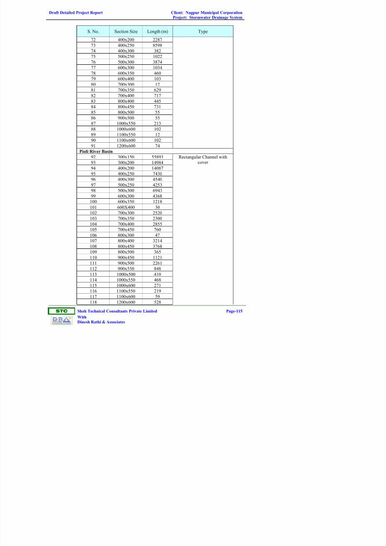
Draft Detailed Project Report Client: Nagpur Municipal Corporation
Project: Stormwater Drainage System
ST
Shah Technical Consultants Private Limited Page-115
With
Dinesh Rathi & Associates
S. No. Section Size Length (m) Type
72 400x200 2287
73 400x250 8598
74 400x300 382
75 500x250 1022
76 500x300 3874
77 600x300 1034
78 600x350 460
79 600x400 103
80 700x300 12
81 700x350 629
82 700x400 717
83 800x400 445
84 800x450 731
85 800x500 55
86 900x500 55
87 1000x550 213
88 1000x600 102
89 1100x550 12
90 1100x600 102
91 1200x600 74
Pioli River Basin
92 300x150 55893
93 300x200 14984
94 400x200 14087
95 400x250 7430
96 400x300 4540
97 500x250 4253
98 500x300 6943
99 600x300 4368
100 600x350 1218
101 600X400 30
102 700x300 2520
103 700x350 2300
104 700x400 2855
105 700x450 760
106 800x300 47
107 800x400 3214
108 800x450 3768
109 800x500 365
110 900x450 1121
111 900x500 2261
112 900x550 848
113 1000x500 410
114 1000x550 468
115 1000x600 271
116 1100x550 219
117 1100x600 59
118 1200x600 528
Rectangular Channel with
cover

Draft Detailed Project Report Client: Nagpur Municipal Corporation
Project: Stormwater Drainage System
ST
Shah Technical Consultants Private Limited Page-116
With
Dinesh Rathi & Associates
S. No. Section Size Length (m) Type
119 1200x650 841
120 1200x700 9
121 1400x700 320
122 1400x800 1178
123 1600x800 282
124 1800x900 617
Table 2.23: Proposed Size, Total Length and Type of Drain (cluster)Section Size (m) Length (m) Section Size (m) Length (m)
300x150 349220 900x500 12531
300x200 123978 900x550 35
350x200 183 900x600 6095
400x200 78274 900x700 56
400x250 76294 1000x500 2298
400x300 43 1000x550 6685
500x250 34268 1000x600 36
500x300 45484 1000x700 278
500x900 7 1000x800 102
600x300 16052 1100x550 2168
600x350 16082 1100x600 5788
660x750 5920 1100x650 1537
600x400 1700 1200x600 1873
700x300 2722 1200x650 2855
700x350 6801 1300x650 1427
700x400 38289 1300x700 5082
700x450 0 1400x700 2013
750x450 163 1400x750 1337
800x300 0 1400x800 298
800x400 7497 1500x750 1207
800x450 16350 1500x800 4167
850x700 106 1600x800 2039
800x500 0 1700x850 10
900x400 0 1800x900 0
900x450 8251
2.2.23 Hydraulic Analysis of the Existing Stormwater Drainage System
For analysis, all the data of the existing network is entered into the stormCAD
Software to make a computer model of the existing stormwater drainage system.
Each drain is further divided into segments, each segment acting as a
concentrated node of the drain receives drainage from a definite area of a sub-
catchment. After running the simulated model the software output has provided
systematic results of the adequacy / inadequacy of each existing storm drain.
Augmentation of Existing System

Draft Detailed Project Report Client: Nagpur Municipal Corporation
Project: Stormwater Drainage System
ST
Shah Technical Consultants Private Limited Page-117
With
Dinesh Rathi & Associates
Whenever the analysis of the existing system shows inadequacy, drains of
higher size have been proposed to increase the system capacity to accommodate
the design storm flow. The Table 2.24 provides details of replacement of
existing drains.
Table 2.24: Details of Replacement of Existing Drains
Survey
Sheet No.
Upstream
Node
Downstream
Node
Size of
Existing
Drain (mm)
Length
(m)
Size of
Proposed
Drain (mm)
5118 60 62 225Ø 65 300x150
5118 61 62 225Ø 205 500x250
5118 62 63 225Ø 115 500x250
5119 37 54 300Ø 52 700x350
5119 47 48 300Ø 50 400x250
5119 48 49 300Ø 40 900x450
5119 53 54 450Ø 65 800x450
5119 54 56 300Ø 25 900x500
5119 56 57 300Ø 55 900x500
5119 78 79 150Ø 45 300x150
5120 1 6 150Ø 125 600x300
5120 4 6 300Ø 65 400x250
5120 6 7 300Ø 45 600x300
5120 10 11 225Ø 175 300x150
5120 12 13 225Ø 115 600x350
5120 27 28 150Ø 30 300x150
5120 85 87 150Ø 90 300x200
5120 86 87 150Ø 100 300x200
5120 87 89 250Ø 50 700x300
5120 89 91 250Ø 10 700x300
5120 91 92 225Ø 225 700x300
5121 1 2 300Ø 738 1300x700
5121 3 4 300Ø 750 1300x700
5121 5 7 300Ø 20 500x300
5121 7 8 225Ø 250 700x300
5121 33 40 300Ø 120 600x300
5121 39 40 300Ø 35 400x250
5121 40 40/A 300Ø 120 600x300
5121 41 43/A 300Ø 48 700x350
5121 59 60 300Ø 240 600x300
5121 39/A 39 300Ø 60 400x200
5121 40/A 41 300Ø 8 600x300
5121 43/A 43 300Ø 15 700x350
5317 43 44 450X400 200 1300X700
5317 56 57 300x300 75 800x450

Draft Detailed Project Report Client: Nagpur Municipal Corporation
Project: Stormwater Drainage System
ST
Shah Technical Consultants Private Limited Page-118
With
Dinesh Rathi & Associates
SurveySheet No.
Upstream Node
Downstream Node
Size ofExisting
Drain (mm)
Length(m)
Size ofProposed
Drain (mm)
5317 58 60 200x200 98 300x150
5317 60 66 200x200 20 300x150
5317 61 63 200x300 108 700x400
5317 62 63 200x300 20 300x150
5317 63 64 200x300 53 700x400
5317 89 90 300x400 55 700x400
5317 90 91 300x400 30 700x400
5317 94 92 150x150 155 700x400
5317 194 195 900x1000 35 1100x650
5317 196 197 900x1000 1060 1100x650
5317 199 200 225Ø 212 700X350
5318 84 85 300Ø 97 300x200
5318 103 104 225Ø 85 500x250
5319 50 51 225Ø 110 300x200
5319 54 57 300Ø 72 300x200
5319 76 77 300Ø 280 300x200
5319 81 99 300Ø 114 300x150
5319 82 100 300Ø 175 300x150
5319 98 99 300Ø 165 700x300
5319 99 100 300Ø 88 300x150
5319 100 101 300Ø 201 300x150
5319 154 158/A 225Ø 114 400x250
5319 163 164 225Ø 459 600x350
5319 165 167 225Ø 142 300x150
5319 166 167 150Ø 112 300x150
5319 167 168 225Ø 80 500x300
5319 206 207 300Ø 190 300x150
5319 215 220 200x100 28 1000x550
5319 43/1 44 300Ø 245 400x200
5320 47 49 450x600 78 700x300
5320 49 50 450x600 95 700x300
5320 52 54 300Ø 78 300x200
5320 53 54 300Ø 115 700x350
5320 54 60/b 450Ø 133 700x450
5320 55 57 225Ø 40 300x150
5320 56 57 225Ø 53 300x150
5320 57 59 300Ø 45 300x150
5320 63 64 300Ø 191 900x450
5320 68 70 300Ø 50 500x300
5320 69 70 300Ø 235 600x300
5320 73 73/1 300Ø 145 900X450
5320 76 73 450Ø 505 600x300
5320 86 88 300Ø 34 300x150

Draft Detailed Project Report Client: Nagpur Municipal Corporation
Project: Stormwater Drainage System
ST
Shah Technical Consultants Private Limited Page-119
With
Dinesh Rathi & Associates
SurveySheet No.
Upstream Node
Downstream Node
Size ofExisting
Drain (mm)
Length(m)
Size ofProposed
Drain (mm)
5320 88 90/A 300Ø 72 400x250
5320 90 90/A 300Ø 482 700x300
5320 100 112 300Ø 425 300x150
5320 101 102/A 300Ø 5 300x200
5320 102 102/A 350Ø 20 300x150
5320 103 110 350Ø 108 400x250
5320 104 105 350Ø 90 500x300
5320 105 103 300Ø 50 300x150
5320 105 107 300Ø 122 400x300
5320 106 107 300Ø 308 300x200
5320 107 109 300Ø 30 300x150
5320 108 109 300Ø 45 700x400
5320 109 110 300Ø 15 300x150
5320 110 112 350Ø 54 700x350
5320 116 121 225Ø 420 400x200
5320 121 117/5 225Ø 95 1000x600
5320 153 154 300Ø 216 400x200
5320 102/A 103 350Ø 90 400x250
5320 117/5 117 450Ø 205 1000x600
5320 60B 60 450Ø 175 300x150
5321 22 23 450Ø 160 1800x900
5321 24 24/1 450Ø 178 400X200
5321 24 24/1 450Ø 271 400x200
5321 24/1 25 450Ø 127 600x300
5322 1 2 225Ø 300 400x200
5322 11 12 250x250 130 300x150
5517 43 44 450x400 200 1300x700
5517 108 109 900x700 145 1000x500
5517 138 140 450Ø 78 300x200
5517 139 152 450Ø 78 500x200
5517 220 222 225Ø 120 1600x800
5517 230 231 300Ø 170 400X300
5517 230 231 300Ø 170 300x200
5517 232 233 500Ø 93 500x250
5517 264 265 600X700 100 400X250
5517 265 264 600x700 337 400x250
5517 267 268 400x500 341 500x300
5517 270 274 300Ø 20 300x150
5517 270 273 300Ø 30 500x200
5517 271 274 300Ø 68 300x150
5517 272 273 225Ø 30 400x250
5517 272 273 225Ø 30 400x250
5517 274 276 500Ø 73 300x150

Draft Detailed Project Report Client: Nagpur Municipal Corporation
Project: Stormwater Drainage System
ST
Shah Technical Consultants Private Limited Page-120
With
Dinesh Rathi & Associates
SurveySheet No.
Upstream Node
Downstream Node
Size ofExisting
Drain (mm)
Length(m)
Size ofProposed
Drain (mm)
5517 274 276 500Ø 73 300x150
5517 276 278 600Ø 63 400x200
5518 8 11 300Ø 42 900x500
5518 9 10 300Ø 268 800x400
5518 13 14 300Ø 135 1500x800
5518 24 27 300Ø 384 800x600
5518 26 31 300Ø 380 600x300
5518 41 46 300Ø 61 700X400
5518 41 43 300Ø 61 700x400
5518 41 46 300Ø 140 700X450
5518 43 45 300Ø 43 700x450
5518 45 46 300Ø 82 700x450
5518 47 52 300Ø 137 700X400
5518 49 51 300Ø 113 500x300
5518 51 52 300Ø 109 500x300
5518 62 68 225Ø 76 300x150
5518 62 66 225Ø 76 300x150
5518 67 72 225Ø 16 300x150
5518 72 74 300Ø 58 300x150
5518 99 100 500x500 56 500x300
5518 113 115 400Ø 50 700x400
5518 114 115 400Ø 75 700X400
5518 115 116 400Ø 40 300x150
5518 143 144 500x500 54 600x300
5518 157 159 900x600 124 1000x500
5518 158 159 900x600 145 1000x500
5518 174 175 225Ø 84 300x150
5518 176 177 225Ø 75 300x150
5518 12/2 10 300Ø 42 1500x800
5518 73/1 83 300Ø 104 700X350
5519 33 35 375Ø 110 700x400
5519 35 37 450Ø 42 700x400
5519 37 39 450Ø 38 700x400
5519 38 39 300Ø 157 300x150
5519 39 47 450Ø 35 700x400
5519 47 56 600Ø 135 700x400
5519 55 56 300Ø 33 300x150
5519 56 60 600Ø 148 700x400
5519 58 157 300Ø 63 400x250
5519 69 71 225Ø 205 500x250
5519 78 79 450Ø 187 1300x700
5519 86 87 300Ø 140 300x200
5519 104 105 300Ø 36 300X150
5519 105 107 300Ø 36 300X150

Draft Detailed Project Report Client: Nagpur Municipal Corporation
Project: Stormwater Drainage System
ST
Shah Technical Consultants Private Limited Page-121
With
Dinesh Rathi & Associates
SurveySheet No.
Upstream Node
Downstream Node
Size ofExisting
Drain (mm)
Length(m)
Size ofProposed
Drain (mm)
5519 107 109 300Ø 39 300X200
5519 109 110 300Ø 39 300X200
5519 135 136 300Ø 370 300x150
5519 137 138 300Ø 323 600x300
5519 139 140 300Ø 172 700x450
5519 149 151 300Ø 113 300x200
5519 150 151 300Ø 181 300x150
5519 151 152 300Ø 65 400x250
5522 1 2 300x400 114 900x500
5522 3 4 300x400 95 900x500
5717 1 3 225Ø 10 400x250
5717 3 4 225Ø 10 600x350
5717 13 14 300Ø 48 400x300
5717 14 15 300Ø 10 700x400
5717 15 16/1 300Ø 60 800x450
5717 15 16 225Ø 91 300x150
5717 17 19 150Ø 17 300x150
5717 21 22 300Ø 140 500 x 300
5717 22 10/A 300Ø 60 700 x 300
5717 25 26 300Ø 92 300 x 150
5717 37 39 225Ø 12 300x 150
5717 37 38 225Ø 12 300x150
5717 37 39 225Ø 12 300x150
5717 38 39 225Ø 12 300x 150
5717 39 41 225Ø 14 300x150
5717 40 41 225Ø 14 300x150
5717 41 43 225Ø 105 300x 150
5717 42 43 225Ø 105 300x 150
5717 43 57 225Ø 52 300x200
5717 45 47 225Ø 60 300x 150
5717 52 54 225Ø 20 300x150
5717 54 56 225Ø 72 400x250
5717 55 56 225Ø 72 300x150
5717 56 57 225Ø 52 400x250
5717 66 68 300Ø 34 300 x 150
5717 70 71 300Ø 17 900x500
5717 71 76 300Ø 65 300 x 150
5717 76 77 300Ø 25 400 x 250
5717 77 78 300Ø 48 700x 300
5717 79 79/B 225Ø 34 300x150
5717 82 85 225Ø 35 500 x 300
5717 84 84/A 225Ø 91 300x 150
5717 84 85 225Ø 34 300x150
5717 85 89 225Ø 11 500 x 300

Draft Detailed Project Report Client: Nagpur Municipal Corporation
Project: Stormwater Drainage System
ST
Shah Technical Consultants Private Limited Page-122
With
Dinesh Rathi & Associates
SurveySheet No.
Upstream Node
Downstream Node
Size ofExisting
Drain (mm)
Length(m)
Size ofProposed
Drain (mm)
5717 88 87 225Ø 80 300x150
5717 89 90 225Ø 24 700x400
5717 89 90 225Ø 10 500x300
5717 93 94 300Ø 232 500x300
5717 96 97 300Ø 38 500x250
5717 97 94 300Ø 232 300x200
5717 99 101 300Ø 35 300x150
5717 100 101 300Ø 70 500X300
5717 101 102 300Ø 70 300x150
5717 102 103 225Ø 70 700x350
5717 115 116 225Ø 67 300x150
5717 117 118 225Ø 10 300x150
5717 117 118 225Ø 63 300x150
5717 119 120 225Ø 223 300x200
5717 121 122 225Ø 142 400x200
5717 143 145 450Ø 237 400x250
5717 144 145 300Ø 237 400x250
5717 145 147 450Ø 120 900x500
5717 147 148 450Ø 55 1100x600
5717 152 153 450X600 160 1100X650
5717 153 154 450X600 124 1100X650
5717 10/A 9/B 300Ø 20 700x 300
5717 131/1 132 300X400 900 900X500
5717 150/A 152 450X600 125 700 X400
5717 84/A 85 225Ø 35 300x 150
5717 9/A 9/B 300Ø 164 700x300
5718 10 12 1000X900 60 1500X800
5718 13 14 1000X900 270 1500X800
5718 21 32 225Ø 75 800x450
5718 27 28 225Ø 76 400x200
5718 30 32 225Ø 41 800x450
5718 31 32 225Ø 90 400X200
5718 34 36 300Ø 42 300x150
5718 36 37 300Ø 27 400x250
5718 38 39 300Ø 8 500X300
5718 40 42 300Ø 12 400x250
5718 41 42 300Ø 73 600X350
5718 42 44 300Ø 25 800x450
5718 43 44 300Ø 74 300x150
5718 44 45 300Ø 10 500x250
5718 48 50 300Ø 27 300x150
5718 50 52/1 300Ø 228 300X200
5718 52 52/1 300Ø 103 400X200
5718 52 53 300Ø 19 500X300
5718 158/1 158 900x600 86 1000x500

Draft Detailed Project Report Client: Nagpur Municipal Corporation
Project: Stormwater Drainage System
ST
Shah Technical Consultants Private Limited Page-123
With
Dinesh Rathi & Associates
SurveySheet No.
Upstream Node
Downstream Node
Size ofExisting
Drain (mm)
Length(m)
Size ofProposed
Drain (mm)
5719 5 6 300Ø 214 1000x550
5719 7 8 300Ø 246 300x150
5719 9 10 300Ø 209 500x300
5719 13 14 300Ø 137 700x400
5719 16 17 1000x900 71 1500X800
5719 18 18/1 1000x900 227 1500X800
5719 19 18/1 1000x900 140 1500X800
5719 21 23 300Ø 50 400x250
5719 22 23 300Ø 58 300x150
5719 23 25 300Ø 30 500X300
5719 24 25 300Ø 64 800x450
5719 25 27 300Ø 30 500X300
5719 25 26 300Ø 60 800x450
5719 27 29 300Ø 13 500X300
5719 28 29 300Ø 54 500x250
5719 29 31 300Ø 12 400x250
5719 30 31 300Ø 124 300x150
5719 31 33 300Ø 20 400x250
5719 33 34 300Ø 68 400x250
5719 48 49 300Ø 98 600x350
5719 50 53 300Ø 294 400x200
5719 51 52 300Ø 48 1000x500
5719 56 57 300Ø 273 300x200
5719 58 59 300Ø 243 300x150
5719 58 58/1 300Ø 50 400X250
5719 60 62 300Ø 188 300x150
5719 61 62 300Ø 55 300x150
5719 63 64 300Ø 30 300x150
5719 66 64 300Ø 36 500x250
5719 67 68 300Ø 74 300x150
5719 88 40 225Ø 39 300X150
5719 94 95 300Ø 157 300x150
5719 106 107 300Ø 75 300x150
5719 108 109 300Ø 80 300x150
5720 17 19 150x200 74 300x150
5720 19 21 150x200 65 300x150
5720 21 22 150x200 139 300x200
5720 23 25 300Ø 239 300x150
5720 24 25 300Ø 67 800x450
5720 25 26 300Ø 108 800X450
5720 27 28 300Ø 328 500X300
5720 29 31 300Ø 178 300x150
5720 30 31 300Ø 126 500x250
5720 31 32 300Ø 155 1100x550

Draft Detailed Project Report Client: Nagpur Municipal Corporation
Project: Stormwater Drainage System
ST
Shah Technical Consultants Private Limited Page-124
With
Dinesh Rathi & Associates
SurveySheet No.
Upstream Node
Downstream Node
Size ofExisting
Drain (mm)
Length(m)
Size ofProposed
Drain (mm)
4517 7 13 225Ø 115 500X250
4517 9 10 225Ø 120 900x450
4517 10 12 225Ø 100 900x450
4517 11 13 225Ø 145 500x250
4517 13 15 300Ø 230 900x500
4517 14 15 300Ø 121 400x250
4517 15 16 300Ø 143 1300x700
4718 15 16 500x400 100 700x350
4718 17 16 500x400 51 300x150
4718 70 71 450Ø 60 1200X600
4918 5 6 300Ø 178 300x150
4919 4 5 300Ø 71 400x600
4919 24 22 300Ø 65 400x250
4919 25 26 300Ø 43 300x200
4919 26 28 300Ø 55 300x200
4919 27 28 300Ø 37 300x150
4919 28 30 300Ø 16 700x300
4919 31 33 300Ø 50 400x250
4919 32 33 300Ø 50 400x250
4919 34 35 300Ø 239 300x150
4919 35 37 300Ø 40 400x250
4919 36 37 300Ø 40 300x200
4919 37 38 300Ø 110 600x300
4919 38 39 300Ø 55 800x400
4919 81 84 300x300 43 400x200
4919 131 132 300Ø 120 400x200
4919 132 124 150Ø 120 300x150
4919 147 151 300Ø 100 300x150
4919 149 151 300Ø 97 300x150
4919 150 151 300Ø 38 300x150
4919 151 152 300Ø 170 300x150
4919 185 186 300x300 89 400x200
4919 191 195 300Ø 193 300X200
4919 192 194 300Ø 75 300x150
4919 193 194 300Ø 71 300x150
4919 194 194/2 300Ø 142 300x150
4919 201 203 300Ø 50 500x250
4919 202 203 300Ø 50 400x200
4919 203 206 300Ø 120 600x300
4919 24/1 24 300Ø 53 300x150
4919 33/2 35 300Ø 226 500x250

Draft Detailed Project Report Client: Nagpur Municipal Corporation
Project: Stormwater Drainage System
ST
Shah Technical Consultants Private Limited Page-125
With
Dinesh Rathi & Associates
2.2.24 Component 2: (Major Drainage Channels) includes Hydrologic and
Hydraulic Analysis of Major Drain Channels i.e. Major and Minor Nallahs
In north zone, there are 25 minor nallahs and 14 major nallahs discharging to
Pioli river.
2.2.24.1 Methodology for Sizing of Nallah Sections
The following methodology have been followed for sizing of nallah section
Step 1 – Assemble site data
A) Data collection
• Topographic, site and location map
• Nallah bed survey
• Historic flood data and local knowledge
B) Environmental constraints
• Floodplain encroachment
• Floodway designation
C) Design criteria
Step 2 - Hydraulic Analysis
Type of hydraulic analysis
- Step backwater analysis
- Survey information needed
- Stream bed profile
- Location of cross section
- Elevation of flood-prone property
- Details of existing structures
- Properties of bed and bank materials

Draft Detailed Project Report Client: Nagpur Municipal Corporation
Project: Stormwater Drainage System
ST
Shah Technical Consultants Private Limited Page-126
With
Dinesh Rathi & Associates
Step 3 – Evaluate Hydrologic Variables
• Compute discharges for selected frequencies
Step 4 – Perform Hydraulic Analysis
• Step backwater Analysis
Step 5 – Calibrate with known high water
• Perform stability analysis
- Hydraulic factors
- Location factors
- Design factors
Step 6 – Design countermeasures
A) Criteria for selection
• Erosion mechanism
• Cost
B) Type of countermeasures
• Bank stabilization
• Channel braiding countermeasures
Step 7 – Documentation
• Prepare report and file with background information
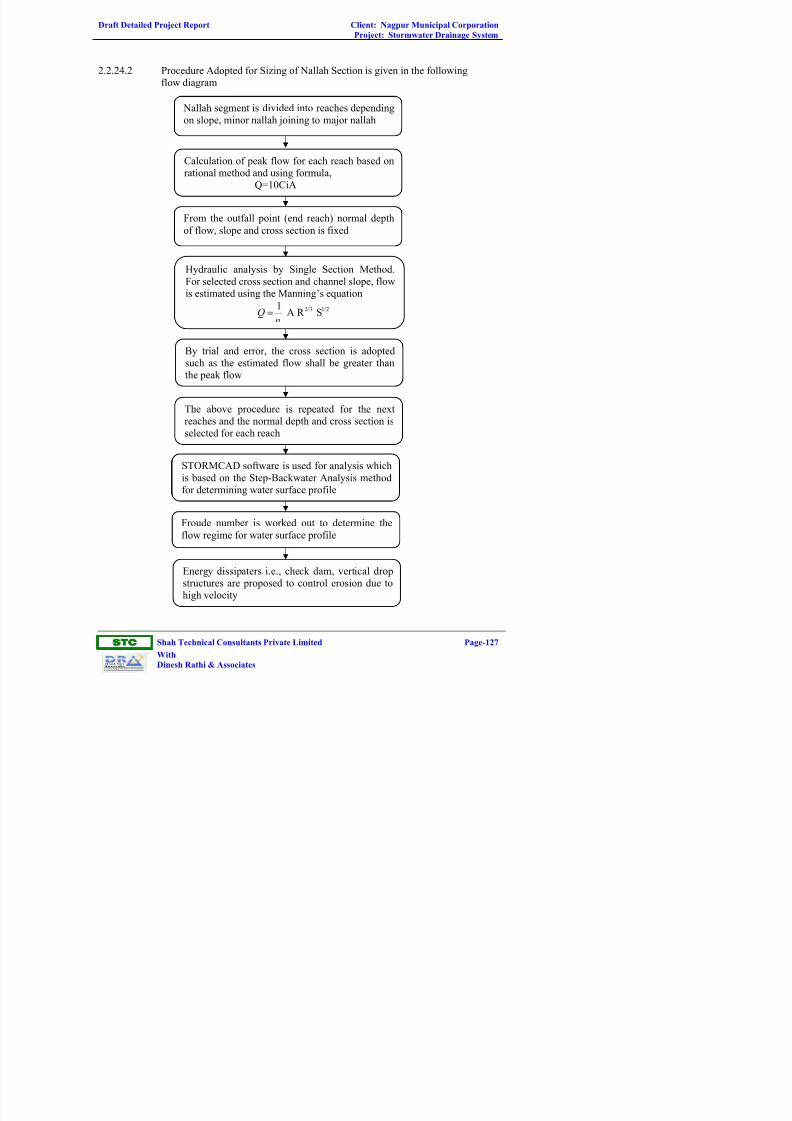
Draft Detailed Project Report Client: Nagpur Municipal Corporation
Project: Stormwater Drainage System
ST
Shah Technical Consultants Private Limited Page-127
With
Dinesh Rathi & Associates
2.2.24.2 Procedure Adopted for Sizing of Nallah Section is given in the following
flow diagram
Nallah segment is divided into reaches depending
on slope, minor nallah joining to major nallah
Calculation of peak flow for each reach based on
rational method and using formula,
Q=10CiA
From the outfall point (end reach) normal depth
of flow, slope and cross section is fixed
Hydraulic analysis by Single Section Method.
For selected cross section and channel slope, flow
is estimated using the Manning’s equation
2/3 1/21A R SQ =
By trial and error, the cross section is adopted
such as the estimated flow shall be greater than
the peak flow
The above procedure is repeated for the next
reaches and the normal depth and cross section is
selected for each reach
STORMCAD software is used for analysis which
is based on the Step-Backwater Analysis method
for determining water surface profile
Froude number is worked out to determine the
flow regime for water surface profile
Energy dissipaters i.e., check dam, vertical drop
structures are proposed to control erosion due to
high velocity

Draft Detailed Project Report Client: Nagpur Municipal Corporation
Project: Stormwater Drainage System
ST
Shah Technical Consultants Private Limited Page-128
With
Dinesh Rathi & Associates
2.2.24.3 Brief Description of 3 Major Nallahs
a) Bor Nallah
This nallah originates from Goutam Nagar, passes through Hajari Pahad
Aakar Nagar, Kolba Swamy Nagar, Defence land and prashant layout
and joins Pioli river at Ayappa Nagar. Length of Bor nallah is 6225 m
and catchment area is nearly 1360 ha. 9 minor nallahs are joining to this
nallah. Based on topography stormwater through road side drainage
network will drain to this nallah through minor nallah and few places
directly to this nallah.
b) Chamar Nallah
This nallah orginates from Timki Nagar passes through Laskhari Bagh,
Jyothi Nagar, Boodha Nagar, Sanjay Gandhi Nagar, Dharmadeep Nagar,
Panchsheel Nagar and joins Pioli river at Sangam Nagar. Length of
nallah is 5610 m and catchment area is nearly 1740 ha. 6 minor nallahs
are joining to this nallah. During monsoon areas such as Dhamma Deep
Nagar, Indira Mata Nagar, Christian Colony, Lumbini Nagar, Mehandi
Bagh road near ring road gets flooded. On both side of nallah wall is
constructed. Based on topography road side drainage network will drain
to this nallah through minor nallahs or directly to this nallah.
Widening and deepening of nallah is proposed.
c) Shanti Nagar Basin
This nallah originates from Netaji Subhash Chandra Bose ward and
passes through Prem Nagar, Shanti Nagar area and finally joint to Pioli
river at Ch.17635 m. Length of nallah is 7710 m and catchment area is
nearly 795 ha. 6 minor nallahs are joining to this nallah. On both side
of nallah wall is constructed upto 4000 m in length. Water logged area
exist between chainage 4950 m to 5400 m. Area along the initial stretch
of nallah gets flooded during monsoon. Based on topography road side
drainage network is draining to this nallah through minor nallahs and
few places directly to this nallah.
Widening of nallah is proposed. The water logged area shall be retained
and developed as shallow wetland.
2.2.24.4 Material of Construction
R.C.C., P.C.C. and stone masonry structure have been studied for nallah
sections.

Draft Detailed Project Report Client: Nagpur Municipal Corporation
Project: Stormwater Drainage System
ST
Shah Technical Consultants Private Limited Page-129
With
Dinesh Rathi & Associates
2.2.24.5 Advantage of R.C.C. Structures over Masonry Structure for Nallah
Section
• The value of ‘n’ will be higher, thereby more discharge in the same section
• Construction is easier and quicker as the machine will be used for mixing
and laying the concrete
• Less width of stem wall, so less space required
• Excavation of foundation will be less
• Discharge in drain can be released after 24 hours against 15 days in case of
Masonry
• Workmanship is easier and the concrete can be compacted by vibrator within
the form work whereas availability of skilled mason for laterite masonry is
difficult
• It is difficult to get huge quantity of good quality laterite stone whereas good
quality of hard granite chips are pleantly available
• R.C.C. is durable and stronger than masonry
• Removal of slush by mechanical means is easier with least damage
• Cost of maintenance is cheaper
Considering the various factors, it is proposed to construct the drains with RCC
structure.
Table 2.25 gives time of concentration of each Nallah and intensity of rainfall.
Table 2.26 provides proposed Nallah / Channel Section, Length & Type. Table
2.27 provides proposed Dimensions of Vertical Drop Structures. Table 2.28
provides Details of proposed Check Dams.
Figure 2.14 to 2.27 shows catchment area of North Zone Nallah.
Figure 2.28 shows proposed typical inlets.

Draft Detailed Project Report Client: Nagpur Municipal Corporation
Project: Stormwater Drainage System
ST
Shah Technical Consultants Private Limited Page-130
With
Dinesh Rathi & Associates
Table 2.25: Catchment Area and Time of Concentration of Nallah Basins (2 yrs Return Period)
S.
No. Name of Nallah
Catchment
Area (ha)
Highest G.L
(m)
Lowest G.L
(m)
Longest
Length
(m)
Slope
Time of
Concentration
Tc (min)
Intensity
(mm/hr)
1 L1 973.38 320.00 308.97 2237 0.0049 57.13 40.80
3 L2 (Ved Nagar Nallah) 375.12 308.00 294.56 1060 0.0127 22.34 76.52
4 L3 (Nara Nallah) 754.96 312.00 303.26 1950 0.0045 53.31 42.74
6 L4 1105.11 302.50 297.80 800 0.0059 24.19 72.56
7 R1 98.30 310.00 307.30 640 0.0042 23.14 74.74
2 R2 (Bor Nallah) 1362.21 367.50 341.33 1460 0.0179 25.02 70.94
5 R3 (ChambarNallah) 1737.20 322.50 300.45 1270 0.0174 22.75 75.60
8 R4 317.49 326.50 318.25 950 0.0087 23.76 73.44
9 R5 59.23 301.50 296.80 750 0.0063 22.45 76.27
10 R6 21.88 303.00 301.20 545 0.0033 22.47 76.23
11 R7 (Taj Nagar Nallah) 59.70 314.50 311.70 645 0.0043 23.03 74.99
12 R8 (Vishwas Nagar Nallah) 27.13 299.50 297.60 555 0.0034 22.48 76.22
13 R9 137.33 287.50 285.40 640 0.0033 25.49 70.05
14 R10 (Shantinagar Nallah) 794.59 307.00 299.70 950 0.0077 24.90 71.16

Draft Detailed Project Report Client: Nagpur Municipal Corporation
Project: Stormwater Drainage System
ST
Shah Technical Consultants Private Limited Page-131
With
Dinesh Rathi & Associates
Table 2.26: Proposed Nallah/Channel Section, Length and Type
ChainageSection Size Proposed
(m)S.
No. Name of Nallah
From ToTop
WidthBottomWidth
WaterDepth
SectionType
Slope(m/km)
Coeffecientof Runoff,Composite
C
Coeffiecientof
Roughness,Composite
n
1 L1 2702 1890 15.0 14.0 0.8 Trapezoidal 4.18 0.55 - 0.57 0.021
1890 1170 19.0 17.8 0.9 " 4.34 0.021
1170 0 22.0 20.7 0.9 " 3.66 0.021
2L2 (Ved Nagar)
3210 2130 6.0 5.1 0.7 " 4.98 0.41 - 0.53 0.021
2130 1080 7.0 6.0 0.8 " 3.85 0.021
1080 838 10.0 8.7 0.8 Trapezoidal 2.94 0.021
838 0 10.0 8.7 0.9 " 3.15 0.021
2.1 L2R1 2580 1710 8.1 7.3 0.6 " 9.01 0.40 - 0.53 0.021
1710 900 9.0 8.2 0.7 " 4.67 0.021
900 0 9.0 8.2 0.6 " 3.48 0.021
3 L3 (Nara) 3545 3000 12.0 11.0 0.8 " 2.42 0.36 - 0.51 0.021
3000 2178 12.0 11.0 0.9 " 2.45 0.021
2178 1286 13.0 12.0 0.9 " 2.52 0.021
1286 810 15.0 13.9 0.9 " 3.63 0.021
810 0 15.0 13.9 0.8 " 3.62 0.021
3.1 L3L1 1445 750 5.0 4.1 0.7 " 10.00 0.53 - 0.55 0.021

Draft Detailed Project Report Client: Nagpur Municipal Corporation
Project: Stormwater Drainage System
ST
Shah Technical Consultants Private Limited Page-132
With
Dinesh Rathi & Associates
ChainageSection Size Proposed
(m)S.
No.
Name of
Nallah
From ToTop
Width
Bottom
Width
Water
Depth
Section
Type
Slope
(m/km)
Coeffecient
of Runoff,
Composite
C
Coeffiecient
of
Roughness,
Composite
n
750 0 8.0 7.0 0.7 " 7.97 0.021
3.2 L3L2 720 0 6.2 5.2 0.9 " 2.34 0.6 0.021
4 L4 10160 8730 10.2 9.1 0.9 " 3.18 0.50 - 0.55 0.021
8730 6390 12.0 10.8 1.1 " 2.36 0.021
6390 3600 12.1 10.7 1.2 " 1.96 0.021
3600 1070 16.0 14.4 1.4 " 1.61 0.021
1070 0 16.0 14.4 1.2 Trapezoidal 1.18 0.021
4.1 L4R1 1465 690 7.0 6.4 0.5 " 4.70 0.52 - 0.6 0.021
690 0 8.0 7.4 0.5 " 3.83 0.021
5 R1 500 0 6.0 5.1 0.6 " 253.00 0.509 0.021
6 R2 (Bor) 6225 5883 6.0 5.4 0.5 " 30.57 0.50 - 0.56 0.021
5883 5721 6.1 5.4 0.5 " 17.78 0.021
5721 5439 6.1 5.4 0.6 " 13.48 0.021
5439 5400 6.3 5.4 0.7 " 10.00 0.021
5400 4514 12.0 11.1 0.9 " 8.70 0.021
4514 4410 12.1 11.1 0.9 " 6.67 0.021
4410 4133 14.0 13.0 1.0 " 5.56 0.021

Draft Detailed Project Report Client: Nagpur Municipal Corporation
Project: Stormwater Drainage System
ST
Shah Technical Consultants Private Limited Page-133
With
Dinesh Rathi & Associates
ChainageSection Size Proposed
(m)S.
No.
Name of
Nallah
From ToTop
Width
Bottom
Width
Water
Depth
Section
Type
Slope
(m/km)
Coeffecient
of Runoff,
Composite
C
Coeffiecient
of
Roughness,
Composite
n
4133 3600 14.0 13.0 1.0 " 5.18 0.021
3600 3564 18.0 16.8 1.0 " 5.00 0.021
3564 2827 18.0 16.8 1.1 " 4.80 0.021
2827 2340 18.0 16.8 1.1 " 4.01 0.021
2340 2110 18.1 16.8 1.2 " 4.00 0.021
2110 1980 18.1 16.8 1.2 " 4.00 0.021
1980 1752 22.2 20.7 1.3 Trapezoidal 3.33 0.021
1752 810 22.2 20.7 1.4 " 3.33 0.021
810 715 25.0 23.5 1.4 " 2.51 0.021
715 0 25.0 23.5 1.2 " 2.18 0.021
6.1 R2 L1 1520 1000 3.2 2.5 0.4 " 16.17 0.40 - 0.66 0.021
1000 450 4.7 3.9 0.6 " 9.31 0.021
450 0 5.1 4.3 0.7 " 7.98 0.021
6.2 R2 L2 1580 1260 3.3 2.5 0.6 " 60.60 0.54 - 0.61 0.021
1260 540 5.2 4.3 0.7 " 14.51 0.021
540 0 6.6 5.6 0.9 " 6.13 0.021
6.3 R2 L3 1890 1260 5.1 4.4 0.6 " 23.67 0.55 - 0.62 0.021

Draft Detailed Project Report Client: Nagpur Municipal Corporation
Project: Stormwater Drainage System
ST
Shah Technical Consultants Private Limited Page-134
With
Dinesh Rathi & Associates
ChainageSection Size Proposed
(m)S.
No.
Name of
Nallah
From ToTop
Width
Bottom
Width
Water
Depth
Section
Type
Slope
(m/km)
Coeffecient
of Runoff,
Composite
C
Coeffiecient
of
Roughness,
Composite
n
1260 630 6.1 5.3 0.7 " 8.65 0.021
630 0 7.2 6.2 0.7 " 5.41 0.021
6.4 R2 L4 980 630 3.2 2.6 0.4 " 56.66 0.57 - 0.61 0.021
630 240 4.1 3.5 0.5 " 19.24 0.021
240 0 6.0 5.4 0.6 " 11.05 0.021
6.5 R2 L5 450 0 4.1 3.5 0.3 " 48.33 0.65 0.021
6.6 R2 R1 1050 540 4.1 3.4 0.4 Trapezoidal 23.08 0.48 - 0.51 0.021
540 0 6.1 5.3 0.7 " 6.45 0.021
6.7 R2 R2 580 0 5.1 4.5 0.3 " 23.77 0.65 0.021
7 R3 (Chamar) 5610 5546 8.0 0.8 Rectangular 3.33 0.52 - 0.62 0.021
5546 5481 8.0 0.8 " 3.34 0.021
5481 5420 11.0 0.6 " 2.23 0.021
5420 5318 11.0 0.6 " 3.33 0.021
5318 5115 11.0 0.6 " 3.33 0.021
5115 4717 13.0 0.8 " 2.92 0.021
4717 4325 13.0 0.8 " 2.77 0.021
4325 3960 13.0 1.2 " 1.67 0.021
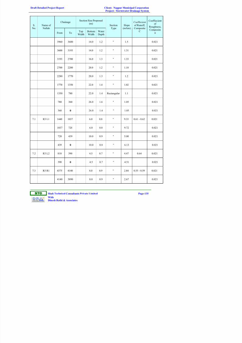
Draft Detailed Project Report Client: Nagpur Municipal Corporation
Project: Stormwater Drainage System
ST
Shah Technical Consultants Private Limited Page-135
With
Dinesh Rathi & Associates
ChainageSection Size Proposed
(m)S.
No.
Name of
Nallah
From ToTop
Width
Bottom
Width
Water
Depth
Section
Type
Slope
(m/km)
Coeffecient
of Runoff,
Composite
C
Coeffiecient
of
Roughness,
Composite
n
3960 3600 14.0 1.2 " 1.5 0.021
3600 3193 14.0 1.2 " 1.31 0.021
3193 2700 16.0 1.3 " 1.33 0.021
2700 2280 20.0 1.2 " 1.18 0.021
2280 1770 20.0 1.3 " 1.2 0.021
1770 1350 22.0 1.4 " 1.02 0.021
1350 780 22.0 1.4 Rectangular 1.1 0.021
780 360 26.0 1.6 " 1.05 0.021
360 0 26.0 1.4 " 1.05 0.021
7.1 R3 L1 1440 1037 6.0 0.8 " 9.33 0.61 - 0.62 0.021
1037 720 6.0 0.8 " 9.72 0.021
720 439 10.0 0.9 " 5.00 0.021
439 0 10.0 0.8 " 6.13 0.021
7.2 R3 L2 810 390 4.5 0.7 " 4.47 0.64 0.021
390 0 4.5 0.7 " 4.51 0.021
7.3 R3 R1 4375 4140 8.0 0.9 " 2.84 0.55 - 0.59 0.021
4140 3890 8.0 0.9 " 2.67 0.021

Draft Detailed Project Report Client: Nagpur Municipal Corporation
Project: Stormwater Drainage System
ST
Shah Technical Consultants Private Limited Page-136
With
Dinesh Rathi & Associates
ChainageSection Size Proposed
(m)S.
No. Name of Nallah
From ToTop
Width
Bottom
Width
Water
Depth
SectionType
Slope(m/km)
Coeffecient
of Runoff,
Composite
C
Coeffiecientof
Roughness,
Compositen
3890 3600 8.0 0.8 " 2.99 0.021
3600 2880 8.0 0.8 " 2.36 0.021
2880 2100 10.0 1.4 " 1.43 0.021
2100 1440 10.0 1.3 " 1.52 0.021
1440 710 11.0 1.4 " 1.31 0.021
710 0 11.0 1.3 " 1.45 0.021
7.4 R3 R2 1775 1380 6.5 0.8 Rectangular 12.12 0.51 - 0.52 0.021
1380 900 7.0 0.8 " 10.00 0.021
900 360 9.0 0.8 " 8.78 0.021
360 0 9.0 0.8 " 6.06 0.021
7.5 R3 R3 1430 870 3.0 0.5 " 8.03 0.54 - 0.61 0.021
870 450 5.5 0.7 " 4.29 0.021
450 0 7.0 0.8 " 3.33 0.021
7.6 R3 R4 330 0 3.0 0.3 " 7.22 0.65 0.021
8 R4 3080 2070 8.0 7 0.8 Trapezoidal 11.76 0.52 - 0.63 0.021
2070 990 10.0 8.8 0.9 " 6.41 0.021
990 0 11.0 9.7 0.9 " 5.65 0.021

Draft Detailed Project Report Client: Nagpur Municipal Corporation
Project: Stormwater Drainage System
ST
Shah Technical Consultants Private Limited Page-137
With
Dinesh Rathi & Associates
ChainageSection Size Proposed
(m)S.
No.
Name of
Nallah
From ToTop
Width
Bottom
Width
Water
Depth
Section
Type
Slope
(m/km)
Coeffecient
of Runoff,
Composite
C
Coeffiecient
of
Roughness,
Composite
n
9 R5 180 0 5.6 4.8 0.5 " 17.04 0.65 0.021
10 R6 710 0 3.0 2.4 0.4 " 11.33 0.604 0.021
11 R7 2270 1484 3.0 2.2 0.6 " 12.60 0.60 - 0.63 0.021
1484 720 3.5 2.6 0.6 " 7.62 0.021
720 0 4.0 3.1 0.6 " 6.49 0.021
12 R8 570 0 4.0 3.4 0.4 " 8.97 0.65 0.021
13 R9 1830 930 12.1 11.2 0.5 Trapezoidal 2.52 0.58 - 0.60 0.021
930 0 14.0 12.9 0.6 " 1.13 0.021
14R10
(Shantinagar)7110 6385 8.0 0.7 Rectangular 3.81 0.54 - 0.61 0.021
6385 6274 8.0 0.7 " 2.86 0.021
6274 5670 8.0 0.7 " 2.86 0.021
5670 5333 11.0 1.0 " 2.20 0.021
5333 5250 13.0 1.0 " 1.93 0.021
5250 4742 13.0 1.0 " 2.00 0.021
4742 4590 13.0 1.0 " 2.00 0.021
4590 4060 16.5 1.2 " 1.65 0.021
4060 3210 16.5 1.1 " 1.69 0.021

Draft Detailed Project Report Client: Nagpur Municipal Corporation
Project: Stormwater Drainage System
ST
Shah Technical Consultants Private Limited Page-138
With
Dinesh Rathi & Associates
ChainageSection Size Proposed
(m)S.
No.
Name of
Nallah
From ToTop
Width
Bottom
Width
Water
Depth
Section
Type
Slope
(m/km)
Coeffecient
of Runoff,
Composite
C
Coeffiecient
of
Roughness,
Composite
n
3210 2255 17.5 1.4 " 1.66 0.021
2255 0 17.5 1.4 " 1.00 0.021
14.1 R10 L1 230 0 2.0 0.4 " 4.60 0.65 0.021
14.2 R10 L2 580 0 1.8 0.5 " 5.22 0.65 0.021
14.3 R10 L3 1190 0 11.0 0.4 " 5.37 0.65 0.021
14.4 R10 L4 230 0 2.1 0.4 " 3.53 0.65 0.021
14.5 R10 R1 380 0 2.5 0.4 Rectangular 6.95 0.65 0.021
14.6 R10 R2 50 0 2.0 0.2 " 6.60 0.65 0.021
2.2.25 Stormwater Inlets (Design)
The hydraulic capacity of a storm drain inlet depends upon its geometry as
well as the characteristics of the gutter flow. Inlet capacity governs both the
rate of water removal from the gutter and the amount of water that can enter
the storm drainage system. Inadequate inlet capacity or poor inlet location
may cause flooding on the roadway resulting in a hazard to the traveling
public.
2.2.25.1 Inlet Types
Storm drain inlets are used to collect runoff and discharge it into storm
drainage system. Inlets are typically located in gutter sections, paved medians.
Inlets used for the drainage of surfaces can be divided into the following four
classes;
1. Grate inlets
2. Curb-opening inlets

Draft Detailed Project Report Client: Nagpur Municipal Corporation
Project: Stormwater Drainage System
ST
Shah Technical Consultants Private Limited Page-139
With
Dinesh Rathi & Associates
3. Slotted inlets
4. Combination inlets
Grate inlets consist of an opening in the gutter or ditch covered by a grate.
Curb-opening inlets are vertical openings in the curb covered by a top slab.
Slotted inlets consist of a pipe cut along the longitudinal axis with bars
perpendicular to the opening to maintain the slotted opening. Combination
inlets consist of both a curb-opening inlet and a grate inlet placed in a side-by-
side configuration, but the curb opening may be located in part upstream of the
grate. Slotted drains may also be used with grates and each type of inlet may
be installed with or without a depression of the gutter.
2.2.25.2 Characteristics and Uses of Inlets
Grate Inlets, perform satisfactorily over a wide range of gutter grades. Grate
inlets generally lose capacity with increase in grade, but to a lesser degree than
curb opening inlets. The principal advantage of grate inlets is that they are
installed along the roadway where the water is flowing. Their principal
disadvantage is that they may be clogged by floating trash or debris. For safety
reasons, preference shall be given to grate inlets where out-of-control vehicles
might be involved.
Curb-opening inlets are most effective on flatter slopes, in sags, and with
flows which typically carry significant amounts of floating debris. The
interception capacity of curb-opening inlets decreases as the gutter grade
steepens. Consequently, the use of curb-opening inlets is recommended in sags
and on grades less than 3%.
Combination inlets provide the advantages of both curb opening and grate
inlets. This combination results in a high capacity inlet which offers the
advantages of both grate and curb opening inlets.
Slotted drain inlets can be used in areas where it is desirable to intercept sheet
flow before it crosses into a section of roadway. Their principal advantage is
their ability to intercept flow over a wide section. However, slotted inlets are
very susceptible to clogging from sediments and debris, and are not
recommended for use in environments where significant sediment or debris
loads may be present. Slotted inlets on a longitudinal grade do have the same
hydraulic capacity as curb openings when debris is not a factor.

Draft Detailed Project Report Client: Nagpur Municipal Corporation
Project: Stormwater Drainage System
ST
Shah Technical Consultants Private Limited Page-140
With
Dinesh Rathi & Associates
2.2.25.3 Inlet Lead Size, Slope and Location
The minimum pipe diameter for all inlet leads is 200 mm. The minimum slope
is 2%. Inlet leads shall be designed without vertical or horizontal bends
whenever possible. If bends are needed, keep to minimum of 22.5o bends.
Each inlet lead must connect directly to a storm sewer, culvert or to an
approved discharge point. When connected to a sewer or culvert less than 600
mm in diameter, the connection must be made at a manhole.
Leads will normally be placed at 90o to a connecting sewer to minimize
conflict during excavation with other underground utilities. Where this is not
practical, such as at intersections, inlets leads shall be placed on the straightest
and most direct practical alignment.
In general gutter inlets are more suitable for use on slopes and curb/ gutter
inlets for use in sags. Gutter inlets have a greater tendency to clog and curb
inlets are inefficient for high velocity flows. Large or high velocity flows may
require multiple inlets or a special inlet design.
2.2.26 Methodology for Sizing of Drains
After the preliminary locations of inlets, connecting pipes and outfalls are
determined, the next step followed is the computation of the rate of discharge
to be carried by each reach of the storm drain and the determination of the size
and slope of drain required to convey this discharge. This is done by starting
at the upstream reach, to the point where the storm drain connects with other
drains or outfall. Rational method is used for determination of discharge in
each reach.
The manning formula is used for determination of capacity of drains. Design
frequencies for storm drain have been followed as per CPHEEO manual.
“STORMCAD-V8 XM edition and STORMCAD version 4.1” software have
been used for the design of stormwater drainage system.

Draft Detailed Project Report Client: Nagpur Municipal Corporation
Project: Stormwater Drainage System
ST
Shah Technical Consultants Private Limited Page-141
With
Dinesh Rathi & Associates
Table 2.27: Dimensions of Vertical Drop Structure
Name of NallahChainage
m
VeryicalDrop,H
(m)
Length, L(m)
Height of
end sill, ∆y(m)
5721 0.7 7.81 0.45Bor Nallah
(Trapezoidal
Section) 5883 0.5 6.99 0.42
360 0.3 8.42 0
780 0.6 10.56 0
1350 0.8 11.88 0.06
1770 0.6 9.89 0
2280 0.8 11.06 0.11
2700 0.7 10.87 0.10
3193 1.0 11.40 0.00
3600 0.9 11.29 0.15
3960 0.9 11.28 0.17
4325 0.9 8.90 0
4717 0.7 8.58 0.33
5115 1.0 8.28 0.19
5318 0.8 7.50 0.30
5420 0.8 7.56 0.33
Chamar
Nallah
(Rectangular
Section)
5550 0.8 8.84 0.36
2255 0.4 8.51 0
3210 1.2 12.09 0.13
4060 1.19 12.26 0.29
4590 1 10.41 0.01
4742 0.58 8.81 0.18
5250 0.75 9.54 0.16
5333 0.65 9.25 0.24
5670 0.7 7.73 0
6274 0.5 6.70 0.14
Shantinagar
Nallah
(Rectangular
Section)
6385 0.8 8.29 0.34