Embed Size (px)
Citation preview
DL1000
GROUP INDEX
GENERAL INFORMATION 1
PERIODIC MAINTENANCE 2
ENGINE 3
FI SYSTEM 4
COOLING AND LUBRICATION SYSTEM 5
CHASSIS 6
ELECTRICAL SYSTEM 7
SERVICING INFORMATION 8
EMISSION CONTROL INFORMATION 9
WIRING DIAGRAM 10
© COPYRIGHT SUZUKI MOTOR CORPORATION 2002
FOREWORDThis manual contains an introductory description onthe SUZUKI DL1000 and procedures for its inspec-tion/service and overhaul of its main components.Other information considered as generally known isnot included.Read the GENERAL INFORMATION section tofamiliarize yourself with the motorcycle and its main-tenance. Use this section as well as other sectionsto use as a guide for proper inspection and service.This manual will help you know the motorcycle bet-ter so that you can assure your customers of fastand reliable service.
!
* This manual has been prepared on the basisof the latest specifications at the time of publi-cation. If modifications have been made sincethen, differences may exist between the con-tent of this manual and the actual motorcycle.
* Illustrations in this manual are used to showthe basic principles of operation and workprocedures. They may not represent theactual motorcycle exactly in detail.
* This manual is written for persons who haveenough knowledge, skills and tools, includingspecial tools, for servicing SUZUKI motorcy-cles. If you do not have the proper knowledgeand tools, ask your authorized SUZUKImotorcycle dealer to help you.
Inexperienced mechanics or mechanicswithout the proper tools and equipmentmay not be able to properly perform theservices described in this manual.Improper repair may result in injury to themechanic and may render the motorcycleunsafe for the rider and passenger.
HOW TO USE THIS MANUALTO LOCATE WHAT YOU ARE LOOKING FOR:1. The text of this manual is divided into sections.2. The section titles are listed in the GROUP INDEX.3. Holding the manual as shown at the right will allow you to find
the first page of the section easily.4. The contents are listed on the first page of each section to
help you find the item and page you need.
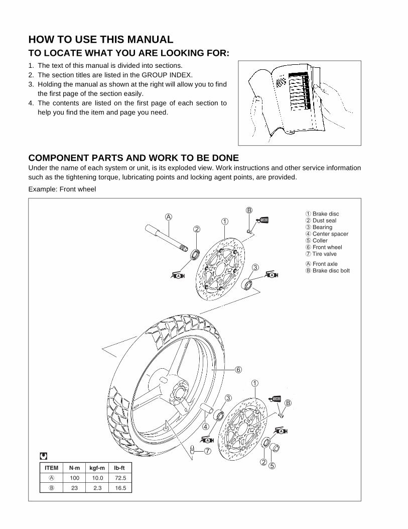
COMPONENT PARTS AND WORK TO BE DONEUnder the name of each system or unit, is its exploded view. Work instructions and other service informationsuch as the tightening torque, lubricating points and locking agent points, are provided.
Example: Front wheel
ITEM N·m kgf-m lb-ft
A 100 10.0 72.5
B 23 2.3 16.5
@
1 Brake disc2 Dust seal3 Bearing4 Center spacer5 Coller6 Front wheel7 Tire valve
A Front axleB Brake disc bolt
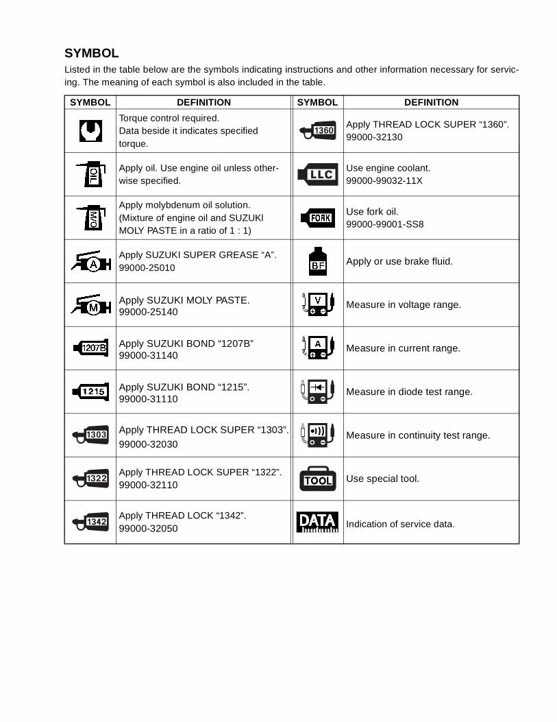
SYMBOLListed in the table below are the symbols indicating instructions and other information necessary for servic-ing. The meaning of each symbol is also included in the table.
SYMBOL DEFINITION SYMBOL DEFINITION
Torque control required.Data beside it indicates specified torque.
Apply THREAD LOCK SUPER “1360”.99000-32130
Apply oil. Use engine oil unless other-wise specified.
Use engine coolant.99000-99032-11X
Apply molybdenum oil solution.(Mixture of engine oil and SUZUKl MOLY PASTE in a ratio of 1 : 1)
Use fork oil.99000-99001-SS8
Apply SUZUKI SUPER GREASE “A”.99000-25010
Apply or use brake fluid.
Apply SUZUKI MOLY PASTE.99000-25140
Measure in voltage range.
Apply SUZUKI BOND “1207B”99000-31140
Measure in current range.
Apply SUZUKI BOND “1215”.99000-31110
Measure in diode test range.
Apply THREAD LOCK SUPER “1303”.
99000-32030Measure in continuity test range.
Apply THREAD LOCK SUPER “1322”.99000-32110
Use special tool.
Apply THREAD LOCK “1342”.99000-32050 Indication of service data.
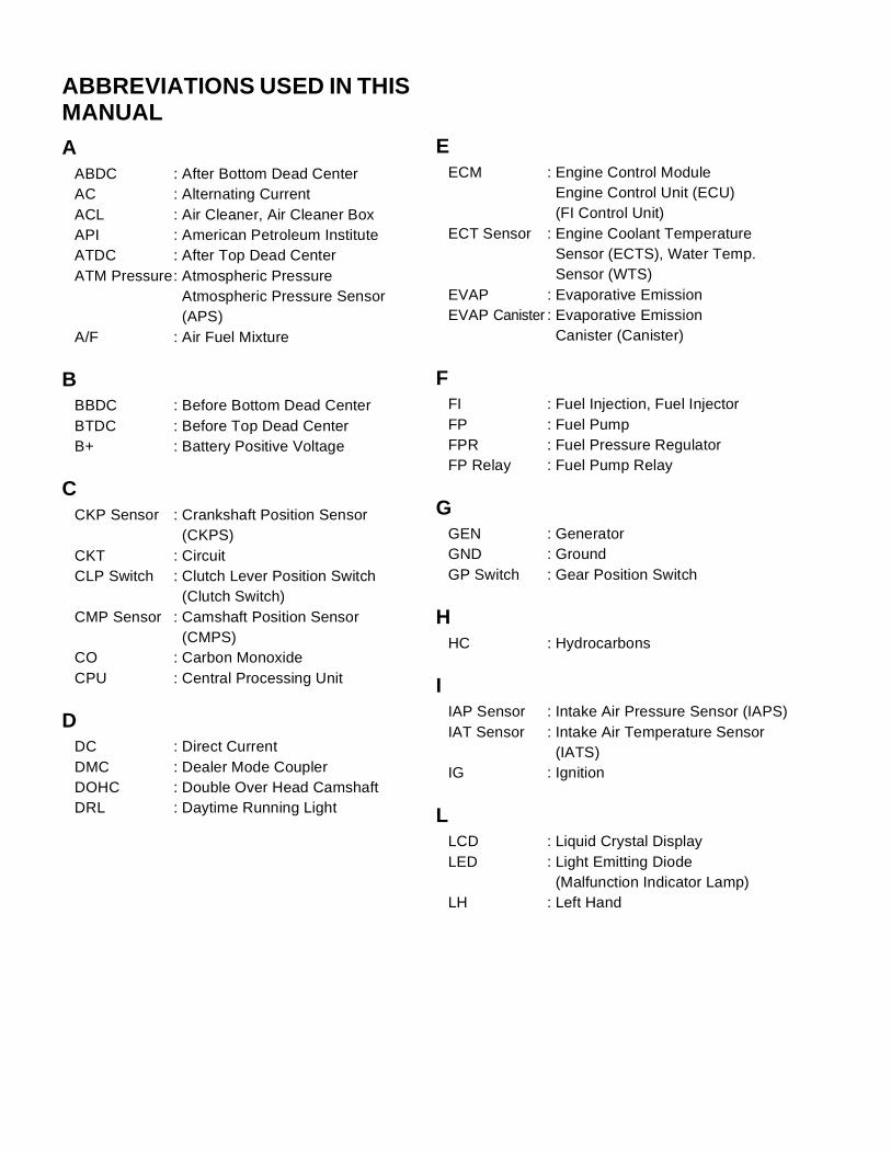
ABBREVIATIONS USED IN THIS MANUALA
ABDC : After Bottom Dead CenterAC : Alternating CurrentACL : Air Cleaner, Air Cleaner BoxAPI : American Petroleum InstituteATDC : After Top Dead CenterATM Pressure: Atmospheric Pressure
Atmospheric Pressure Sensor (APS)
A/F : Air Fuel Mixture
BBBDC : Before Bottom Dead CenterBTDC : Before Top Dead CenterB+ : Battery Positive Voltage
CCKP Sensor : Crankshaft Position Sensor
(CKPS)CKT : CircuitCLP Switch : Clutch Lever Position Switch
(Clutch Switch)CMP Sensor : Camshaft Position Sensor
(CMPS)CO : Carbon MonoxideCPU : Central Processing Unit
DDC : Direct CurrentDMC : Dealer Mode CouplerDOHC : Double Over Head CamshaftDRL : Daytime Running Light
EECM : Engine Control Module
Engine Control Unit (ECU)(FI Control Unit)
ECT Sensor : Engine Coolant TemperatureSensor (ECTS), Water Temp.Sensor (WTS)
EVAP : Evaporative EmissionEVAP Canister : Evaporative Emission
Canister (Canister)
FFI : Fuel Injection, Fuel InjectorFP : Fuel PumpFPR : Fuel Pressure RegulatorFP Relay : Fuel Pump Relay
GGEN : GeneratorGND : GroundGP Switch : Gear Position Switch
HHC : Hydrocarbons
IIAP Sensor : Intake Air Pressure Sensor (IAPS)IAT Sensor : Intake Air Temperature Sensor
(IATS)IG : Ignition
LLCD : Liquid Crystal DisplayLED : Light Emitting Diode
(Malfunction Indicator Lamp)LH : Left Hand
MMAL-Code : Malfunction Code
(Diagnostic Code)Max : MaximumMIL : Malfunction Indicator Lamp
(LED)Min : Minimum
NNOx : Nitrogen Oxides
OOHC : Over Head CamshaftOPS : Oil Pressure Switch
PPCV : Positive Crankcase
Ventilation (Crankcase Breather)
RRH : Right HandROM : Read Only Memory
SSAE : Society of Automotive EngineersSTC System : Secondary Throttle Control
System (STCS)STP Sensor : Secondary Throttle Position
Sensor (STPS)ST Valve : Secondary Throttle Valve (STV)STV Actuator : Secondary Throttle Valve Actuator
(STVA)
TTO Sensor : Tip Over Sensor (TOS)TP Sensor : Throttle Position Sensor (TPS)
VVD : Vacuum Damper
1
GENERAL INFORMATION 1-1
CONTENTS
GENERAL INFORMATION
WARNING/CAUTION/NOTE ...............................................................1- 2
GENERAL PRECAUTIONS ................................................................1- 2
SUZUKI DL1000K2 (’02-MODEL) ......................................................1- 4
SERIAL NUMBER LOCATION ...........................................................1- 4
FUEL, OIL AND ENGINE COOLANT RECOMMENDATION .............1- 4
FUEL ............................................................................................1- 4
ENGINE OIL .................................................................................1- 5
BRAKE FLUID .............................................................................1- 5
FRONT FORK OIL .......................................................................1- 5
ENGINE COOLANT .....................................................................1- 5
WATER FOR MIXING ..................................................................1- 5
ANTI-FREEZE/ENGINE COOLANT ............................................1- 5
LIQUID AMOUNT OF WATER/ENGINE COOLANT ...................1- 5
BREAK-lN PROCEDURES .................................................................1- 6
CYLINDER IDENTIFICATION ............................................................1- 6
INFORMATION LABELS ....................................................................1- 7
SPECIFICATIONS ..............................................................................1- 8
COUNTRY AND AREA CODES .........................................................1-10

1-2 GENERAL INFORMATION
WARNING/CAUTION/NOTEPlease read this manual and follow its instructions carefully. To emphasize special information, the symboland the words WARNING, CAUTION and NOTE have special meanings. Pay special attention to the mes-sages highlighted by these signal words.
!Indicates a potential hazard that could result in death or injury.
"Indicates a potential hazard that could result in motorcycle damage.
NOTE:Indicates special information to make maintenance easier or instructions clearer.
Please note, however, that the warnings and cautions contained in this manual cannot possibly cover allpotential hazards relating to the servicing, or lack of servicing, of the motorcycle. In addition to the WARN-INGS and CAUTIONS stated, you must use good judgement and basic mechanical safety principles. If youare unsure about how to perform a particular service operation, ask a more experienced mechanic foradvice.
GENERAL PRECAUTIONS!
* Proper service and repair procedures are important for the safety of the service mechanic andthe safety and reliability of the motorcycle.
* When 2 or more persons work together, pay attention to the safety of each other.* When it is necessary to run the engine indoors, make sure that exhaust gas is forced out-
doors.* When working with toxic or flammable materials, make sure that the area you work in is well-
ventilated and that you follow all of the material manufacturer’s instructions.* Never use gasoline as a cleaning solvent.* To avoid getting burned, do not touch the engine, engine oil, radiator and exhaust system
until they have cooled.* After servicing the fuel, oil, water, exhaust or brake systems, check all lines and fittings
related to the system for leaks.

GENERAL INFORMATION 1-3
"* If parts replacement is necessary, replace the parts with Suzuki Genuine Parts or their equiva-
lent.* When removing parts that are to be reused, keep them arranged in an orderly manner so that
they may be reinstalled in the proper order and orientation.* Be sure to use special tools when instructed.* Make sure that all parts used in reassembly are clean. Lubricate them when specified.* Use the specified lubricant, bond, or sealant.* When removing the battery, disconnect the negative cable first and then the positive cable.* When reconnecting the battery, connect the positive cable first and then the negative cable,
and replace the terminal cover on the positive terminal.* When performing service to electrical parts, if the service procedures not require use of bat-
tery power, disconnect the negative cable the battery.* When tightening the cylinder head and case bolts and nuts, tighten the larger sizes first.
Always tighten the bolts and nuts diagonally from the inside toward outside and to the speci-fied tightening torque.
* Whenever you remove oil seals, gaskets, packing, O-rings, locking washers, self-lockingnuts, cotter pins, circlips and certain other parts as specified, be sure to replace them withnew ones. Also, before installing these new parts, be sure to remove any left over materialfrom the mating surfaces.
* Never reuse a circlip. When installing a new circlip, take care not to expand the end gap largerthan required to slip the circlip over the shaft. After installing a circlip, always ensure that it iscompletely seated in its groove and securely fitted.
* Use a torque wrench to tighten fasteners to the specified torque. Wipe off grease and oil if athread is smeared with them.
* After reassembling, check parts for tightness and proper operation.
* To protect the environment, do not unlawfully dispose of used motor oil, engine coolant andother fluids: batteries, and tires.
* To protect Earth’s natural resources, properly dispose of used motorcycle and parts.
1-4 GENERAL INFORMATION
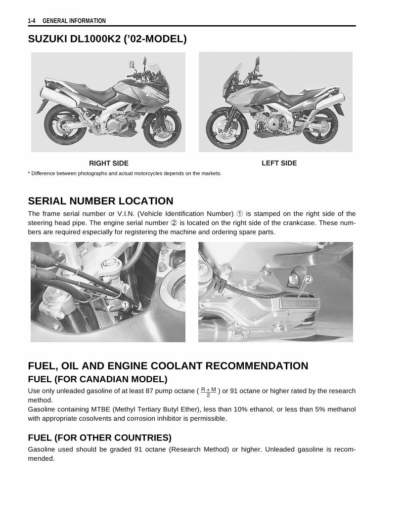
SUZUKI DL1000K2 (’02-MODEL)
* Difference between photographs and actual motorcycles depends on the markets.
SERIAL NUMBER LOCATIONThe frame serial number or V.I.N. (Vehicle Identification Number)
1 is stamped on the right side of thesteering head pipe. The engine serial number
2 is located on the right side of the crankcase. These num-bers are required especially for registering the machine and ordering spare parts.
FUEL, OIL AND ENGINE COOLANT RECOMMENDATIONFUEL (FOR CANADIAN MODEL)Use only unleaded gasoline of at least 87 pump octane ( ) or 91 octane or higher rated by the researchmethod.Gasoline containing MTBE (Methyl Tertiary Butyl Ether), less than 10% ethanol, or less than 5% methanolwith appropriate cosolvents and corrosion inhibitor is permissible.
FUEL (FOR OTHER COUNTRIES)Gasoline used should be graded 91 octane (Research Method) or higher. Unleaded gasoline is recom-mended.
RIGHT SIDE LEFT SIDE
2R + M
GENERAL INFORMATION 1-5
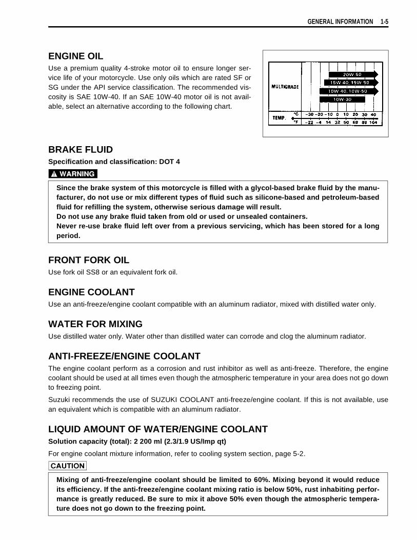
ENGINE OILUse a premium quality 4-stroke motor oil to ensure longer ser-vice life of your motorcycle. Use only oils which are rated SF orSG under the API service classification. The recommended vis-cosity is SAE 10W-40. If an SAE 10W-40 motor oil is not avail-able, select an alternative according to the following chart.
BRAKE FLUIDSpecification and classification: DOT 4
!
FRONT FORK OILUse fork oil SS8 or an equivalent fork oil.
ENGINE COOLANTUse an anti-freeze/engine coolant compatible with an aluminum radiator, mixed with distilled water only.
WATER FOR MIXINGUse distilled water only. Water other than distilled water can corrode and clog the aluminum radiator.
ANTI-FREEZE/ENGINE COOLANTThe engine coolant perform as a corrosion and rust inhibitor as well as anti-freeze. Therefore, the enginecoolant should be used at all times even though the atmospheric temperature in your area does not go downto freezing point.
Suzuki recommends the use of SUZUKI COOLANT anti-freeze/engine coolant. If this is not available, usean equivalent which is compatible with an aluminum radiator.
LIQUID AMOUNT OF WATER/ENGINE COOLANTSolution capacity (total): 2 200 ml (2.3/1.9 US/Imp qt)
For engine coolant mixture information, refer to cooling system section, page 5-2.
"
Since the brake system of this motorcycle is filled with a glycol-based brake fluid by the manu-facturer, do not use or mix different types of fluid such as silicone-based and petroleum-basedfluid for refilling the system, otherwise serious damage will result.Do not use any brake fluid taken from old or used or unsealed containers.Never re-use brake fluid left over from a previous servicing, which has been stored for a longperiod.
Mixing of anti-freeze/engine coolant should be limited to 60%. Mixing beyond it would reduceits efficiency. If the anti-freeze/engine coolant mixing ratio is below 50%, rust inhabiting perfor-mance is greatly reduced. Be sure to mix it above 50% even though the atmospheric tempera-ture does not go down to the freezing point.
1-6 GENERAL INFORMATION
BREAK-lN PROCEDURESDuring manufacture only the best possible materials are used and all machined parts are finished to a veryhigh standard but it is still necessary to allow the moving parts to “BREAK-IN” before subjecting the engineto maximum stresses. The future performance and reliability of the engine depends on the care and restraintexercised during its early life. The general rules are as follows.
• Keep to these break-in engine speed limits:
Initial 800 km ( 500 miles): Below 4 500 r/minUp to 1 600 km (1 000 miles): Below 7 000 r/minOver 1 600 km (1 000 miles): Below 9 500 r/min
• Upon reaching an odometer reading of 1 600 km (1 000 miles) you can subject the motorcycle to full throt-tle operation. However, do not exceed 9 500 r/min at any time.
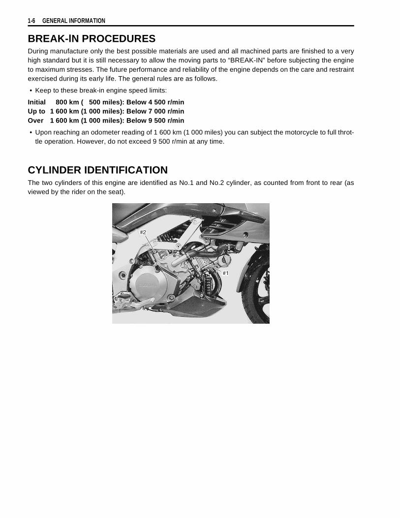
CYLINDER IDENTIFICATIONThe two cylinders of this engine are identified as No.1 and No.2 cylinder, as counted from front to rear (asviewed by the rider on the seat).
#1
#2
GENERAL INFORMATION 1-7
INFORMATION LABELS
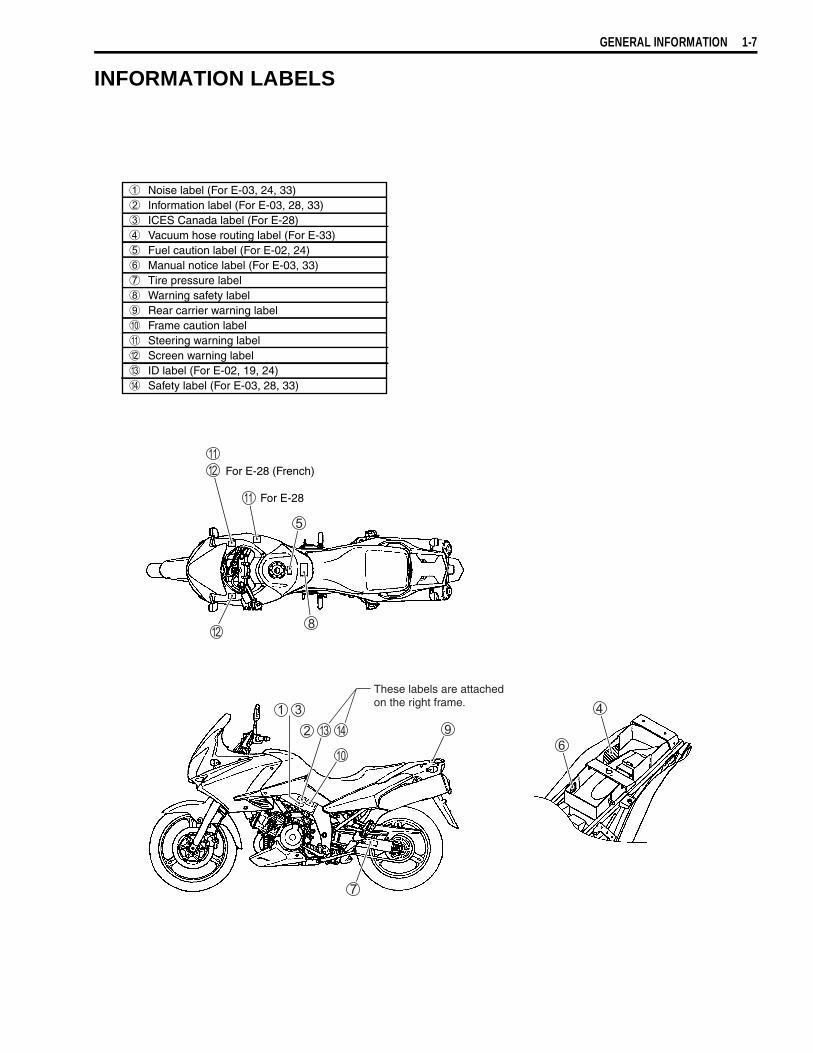
1 Noise label (For E-03, 24, 33)2 Information label (For E-03, 28, 33)3 ICES Canada label (For E-28)4 Vacuum hose routing label (For E-33)5 Fuel caution label (For E-02, 24)6 Manual notice label (For E-03, 33)7 Tire pressure label8 Warning safety label9 Rear carrier warning label0 Frame caution labelA Steering warning labelB Screen warning labelC ID label (For E-02, 19, 24)D Safety label (For E-03, 28, 33)
For E-28 (French)
For E-28
These labels are attachedon the right frame.
1-8 GENERAL INFORMATION
SPECIFICATIONSDIMENSIONS AND DRY MASSOverall length.......................................................2 295 mm (90.4 in)Overall width ........................................................ 865 mm (34.1 in)Overall height.......................................................1 335 mm (52.6 in)Wheelbase...........................................................1 535 mm (60.4 in)Ground clearance ................................................ 165 mm ( 6.5 in)Seat height........................................................... 840 mm (33.1 in)Dry mass.............................................................. 207 kg (456 lbs)
209 kg (461 lbs) .........E-33
ENGINEType .....................................................................Four-stroke, Liquid-cooled, DOHC, 90-degree V-twinNumber of cylinders .............................................2Bore .....................................................................98.0 mm (3.858 in)Stroke...................................................................66.0 mm (2.598 in)Piston displacement.............................................996 cm³ (60.8 cu. in)Compression ratio................................................11.3 : 1Fuel system..........................................................Fuel injection systemAir cleaner............................................................Non-woven fabric elementStarter system......................................................Electric starterLubrication system ...............................................Wet sump
DRIVE TRAINClutch...................................................................Wet multi-plate typeTransmission........................................................6-speed constant meshGearshift pattern ..................................................1-down, 5-upPrimary reduction ratio.........................................1.838 (57/31)Final reduction ratio .............................................2.411 (41/17)Gear ratios, Low ..................................................3.000 (36/12)
2nd...................................................1.933 (29/15)3rd ...................................................1.500 (27/18)4th....................................................1.227 (27/22)5th....................................................1.086 (25/23)Top ..................................................0.913 (21/23)
Drive chain ...........................................................RK525 SMOZ7, 112 links
GENERAL INFORMATION 1-9
CHASSISFront suspension................................................. Inverted telescopic, coil spring, oil dampedRear suspension ................................................. Link type, coil spring, oil dampedSteering angle ..................................................... 40° (right & left)Caster.................................................................. 26° 30’Trail ..................................................................... 111 mm (4.3 in)Turning radius ..................................................... 2.7 m (8.86 ft)Front brake.......................................................... Disc brake, twinRear brake .......................................................... Disc brakeFront tire size ...................................................... 110/80 R19M/C 59H, tubelessRear tire size ....................................................... 150/70 R17M/C 69H, tubelessFront fork stroke .................................................. 160 mm (6.3 in)Rear wheel travel ................................................ 159 mm (6.2 in)
ELECTRICAL lgnition type ......................................................... Electronic ignition (ECM, Transistorized)lgnition timing ...................................................... 4° B. T. D. C at 1 200 r/minSpark plug ........................................................... NGK: CR8EK or DENSO: U24ETRBattery................................................................. 12 V 43.2 kC (12 Ah)/10 HRGenerator ............................................................ Three-phase A.C. GeneratorFuse .................................................................... 30/15/15/15/15/15/10 AHeadlight ............................................................. 12 V 60/55 W H4Position light........................................................ 12 V 5 W × 2.........Except for E-03, 24, 28, 33Turn signal light................................................... 12 V 10 WLicense light ........................................................ 12 V 5 WBrake light/Taillight .............................................. 12 V 21/5 W ×2Speedometer/Tachometer light........................... LEDNeutral indicator light .......................................... LEDHigh beam indicator light..................................... LEDTurn signal indicator light .................................... LEDOver drive indicator light ..................................... LEDFuel injector warning light ................................... LEDEngine coolant temperature warning light........... LEDOil pressure warning light.................................... LED
CAPACITIES Fuel tank ............................................................. 22 L (5.8/4.8 US/Imp gal)Engine oil, oil change ........................................ 2 700 ml (2.9/2.4 US/Imp qt)
with filter change.............................. 2 900 ml (3.1/2.6 US/Imp qt)overhaul ........................................... 3 300 ml (3.5/2.9 US/Imp qt)
Engine coolant, including reserve ....................... 2 200 ml (2.3/1.9 US/Imp oz)Front fork oil (each leg) ....................................... 505 ml (17.1/17.8 US/Imp oz)
These specifications are subject to change without notice.
1-10 GENERAL INFORMATION
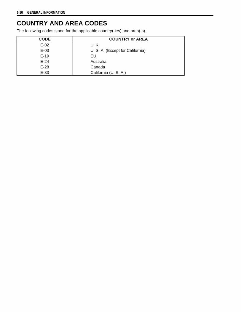
COUNTRY AND AREA CODESThe following codes stand for the applicable country(-ies) and area(-s).
CODE COUNTRY or AREAE-02E-03E-19E-24E-28E-33
U. K.U. S. A. (Except for California)EUAustraliaCanadaCalifornia (U. S. A.)
2
6
PERIODIC MAINTENANCE 2-1
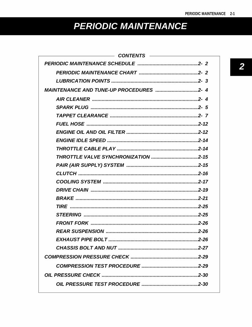
CONTENTS
PERIODIC MAINTENANCE
PERIODIC MAINTENANCE SCHEDULE ............................................2- 2
PERIODIC MAINTENANCE CHART ...........................................2- 2
LUBRICATION POINTS ...............................................................2- 3
MAINTENANCE AND TUNE-UP PROCEDURES ...............................2- 4
AIR CLEANER .............................................................................2- 4
SPARK PLUG ..............................................................................2- 5
TAPPET CLEARANCE ................................................................2- 7
FUEL HOSE .................................................................................2-12
ENGINE OIL AND OIL FILTER ....................................................2-12
ENGINE IDLE SPEED ..................................................................2-14
THROTTLE CABLE PLAY ...........................................................2-14
THROTTLE VALVE SYNCHRONIZATION ..................................2-15
PAIR (AIR SUPPLY) SYSTEM ....................................................2-15
CLUTCH .......................................................................................2-16
COOLING SYSTEM .....................................................................2-17
DRIVE CHAIN ..............................................................................2-19
BRAKE .........................................................................................2-21
TIRE .............................................................................................2-25
STEERING ...................................................................................2-25
FRONT FORK ..............................................................................2-26
REAR SUSPENSION ...................................................................2-26
EXHAUST PIPE BOLT .................................................................2-26
CHASSIS BOLT AND NUT ..........................................................2-27
COMPRESSION PRESSURE CHECK .................................................2-29
COMPRESSION TEST PROCEDURE .........................................2-29
OIL PRESSURE CHECK ......................................................................2-30
OIL PRESSURE TEST PROCEDURE .........................................2-30
2-2 PERIODIC MAINTENANCE
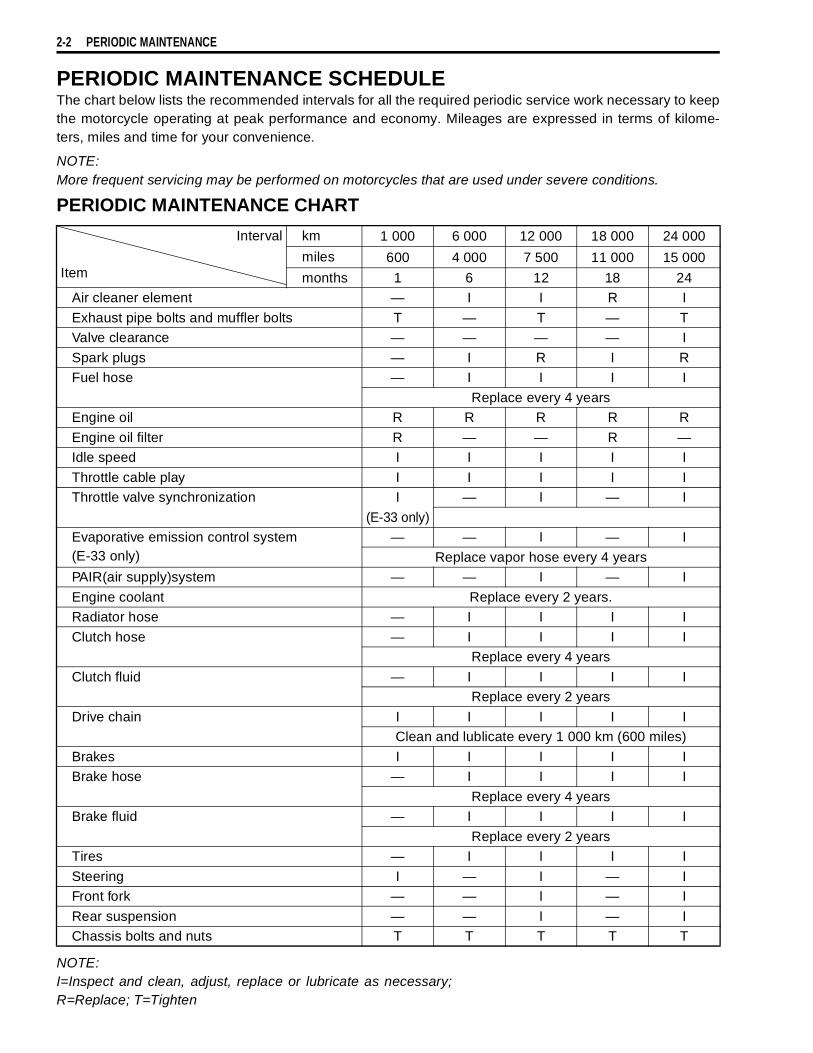
PERIODIC MAINTENANCE SCHEDULEThe chart below lists the recommended intervals for all the required periodic service work necessary to keepthe motorcycle operating at peak performance and economy. Mileages are expressed in terms of kilome-ters, miles and time for your convenience.
NOTE:More frequent servicing may be performed on motorcycles that are used under severe conditions.
PERIODIC MAINTENANCE CHART
NOTE:I=Inspect and clean, adjust, replace or lubricate as necessary;R=Replace; T=Tighten
Interval
Item
km 1 000 6 000 12 000 18 000 24 000
miles 600 4 000 7 500 11 000 15 000
months 1 6 12 18 24Air cleaner element — I I R I
Exhaust pipe bolts and muffler bolts T — T — TValve clearance — — — — I
Spark plugs — I R I RFuel hose — I I I I
Replace every 4 yearsEngine oil R R R R R
Engine oil filter R — — R —Idle speed I I I I I
Throttle cable play I I I I IThrottle valve synchronization I — I — I
(E-33 only)Evaporative emission control system(E-33 only)
— — I — I
Replace vapor hose every 4 yearsPAIR(air supply)system — — I — I
Engine coolant Replace every 2 years.Radiator hose — I I I I
Clutch hose — I I I IReplace every 4 years
Clutch fluid — I I I IReplace every 2 years
Drive chain I I I I IClean and lublicate every 1 000 km (600 miles)
Brakes I I I I IBrake hose — I I I I
Replace every 4 yearsBrake fluid — I I I I
Replace every 2 yearsTires — I I I I
Steering I — I — IFront fork — — I — I
Rear suspension — — I — IChassis bolts and nuts T T T T T
PERIODIC MAINTENANCE 2-3
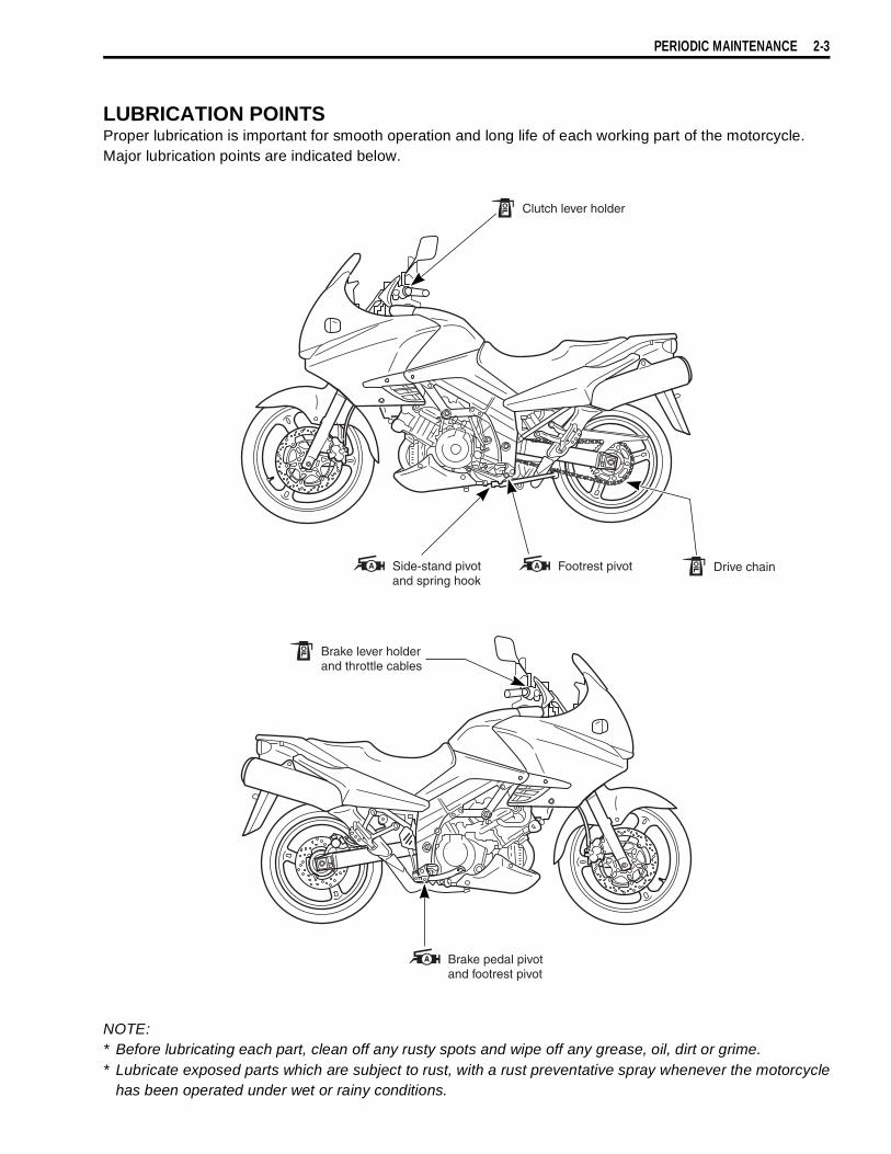
LUBRICATION POINTSProper lubrication is important for smooth operation and long life of each working part of the motorcycle.Major lubrication points are indicated below.
NOTE:* Before lubricating each part, clean off any rusty spots and wipe off any grease, oil, dirt or grime.* Lubricate exposed parts which are subject to rust, with a rust preventative spray whenever the motorcycle
has been operated under wet or rainy conditions.
Clutch lever holder
Brake lever holderand throttle cables
Drive chainSide-stand pivot and spring hook
Brake pedal pivotand footrest pivot
Footrest pivot
2-4 PERIODIC MAINTENANCE
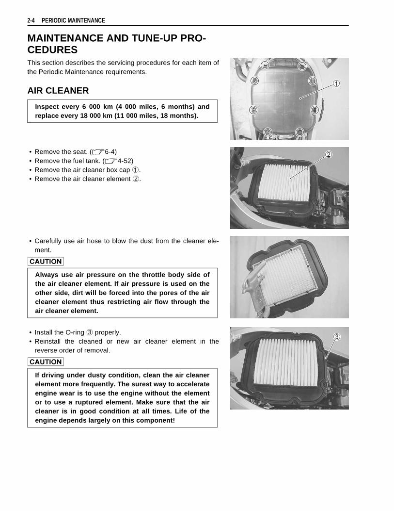
MAINTENANCE AND TUNE-UP PRO-CEDURESThis section describes the servicing procedures for each item ofthe Periodic Maintenance requirements.
AIR CLEANER
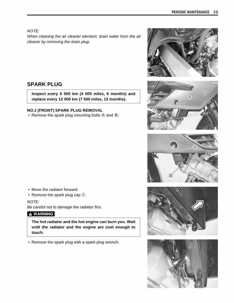
• Remove the seat. (!6-4)• Remove the fuel tank. (!4-52)• Remove the air cleaner box cap
1.• Remove the air cleaner element
2.
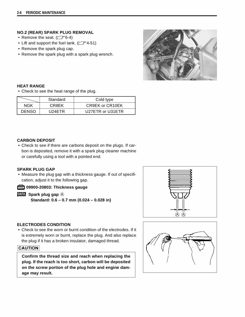
• Carefully use air hose to blow the dust from the cleaner ele-ment.
"
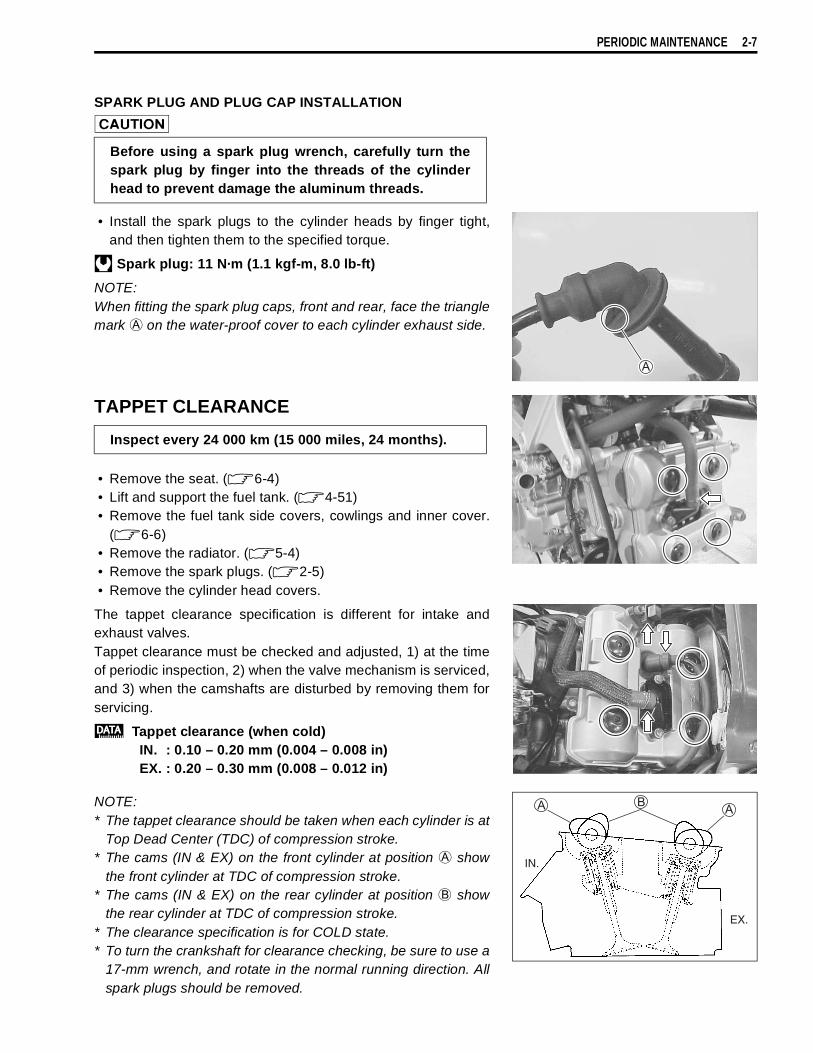
• Install the O-ring
3 properly.• Reinstall the cleaned or new air cleaner element in the
reverse order of removal.
"
Inspect every 6 000 km (4 000 miles, 6 months) andreplace every 18 000 km (11 000 miles, 18 months).
Always use air pressure on the throttle body side ofthe air cleaner element. If air pressure is used on theother side, dirt will be forced into the pores of the aircleaner element thus restricting air flow through theair cleaner element.
If driving under dusty condition, clean the air cleanerelement more frequently. The surest way to accelerateengine wear is to use the engine without the elementor to use a ruptured element. Make sure that the aircleaner is in good condition at all times. Life of theengine depends largely on this component!
PERIODIC MAINTENANCE 2-5
NOTE:When cleaning the air cleaner element, drain water from the aircleaner by removing the drain plug.
SPARK PLUG
NO.1 (FRONT) SPARK PLUG REMOVAL• Remove the spark plug mounting bolts
A and
B.
• Move the radiator forward.• Remove the spark plug cap
1.
NOTE:Be careful not to damage the radiator fins.
#
• Remove the spark plug with a spark plug wrench.
Inspect every 6 000 km (4 000 miles, 6 months) andreplace every 12 000 km (7 500 miles, 12 months).
The hot radiator and the hot engine can burn you. Waituntil the radiator and the engine are cool enough totouch.
2-6 PERIODIC MAINTENANCE
NO.2 (REAR) SPARK PLUG REMOVAL• Remove the seat. (!6-4)• Lift and support the fuel tank. (!4-51)• Remove the spark plug cap.• Remove the spark plug with a spark plug wrench.
HEAT RANGE• Check to see the heat range of the plug.
CARBON DEPOSIT• Check to see if there are carbons deposit on the plugs. If car-
bon is deposited, remove it with a spark plug cleaner machineor carefully using a tool with a pointed end.
SPARK PLUG GAP• Measure the plug gap with a thickness gauge. If out of specifi-
cation, adjust it to the following gap.
$ 09900-20803: Thickness gauge
% Spark plug gap
A
Standard: 0.6 – 0.7 mm (0.024 – 0.028 in)
ELECTRODES CONDITION• Check to see the worn or burnt condition of the electrodes. If it
is extremely worn or burnt, replace the plug. And also replacethe plug if it has a broken insulator, damaged thread.
"
Standard Cold type
NGK CR8EK CR9EK or CR10EKDENSO U24ETR U27ETR or U31ETR
Confirm the thread size and reach when replacing theplug. If the reach is too short, carbon will be depositedon the screw portion of the plug hole and engine dam-age may result.
PERIODIC MAINTENANCE 2-7
SPARK PLUG AND PLUG CAP INSTALLATION
"
• Install the spark plugs to the cylinder heads by finger tight,and then tighten them to the specified torque.
& Spark plug: 11 N·m (1.1 kgf-m, 8.0 lb-ft)
NOTE:When fitting the spark plug caps, front and rear, face the trianglemark
A on the water-proof cover to each cylinder exhaust side.
TAPPET CLEARANCE
• Remove the seat. (!6-4)• Lift and support the fuel tank. (!4-51)• Remove the fuel tank side covers, cowlings and inner cover.
(!6-6)• Remove the radiator. (!5-4)• Remove the spark plugs. (!2-5)• Remove the cylinder head covers.
The tappet clearance specification is different for intake andexhaust valves.Tappet clearance must be checked and adjusted, 1) at the timeof periodic inspection, 2) when the valve mechanism is serviced,and 3) when the camshafts are disturbed by removing them forservicing.
% Tappet clearance (when cold)IN. : 0.10 – 0.20 mm (0.004 – 0.008 in)EX. : 0.20 – 0.30 mm (0.008 – 0.012 in)
NOTE:* The tappet clearance should be taken when each cylinder is at
Top Dead Center (TDC) of compression stroke.* The cams (IN & EX) on the front cylinder at position
A showthe front cylinder at TDC of compression stroke.
* The cams (IN & EX) on the rear cylinder at position
B showthe rear cylinder at TDC of compression stroke.
* The clearance specification is for COLD state.* To turn the crankshaft for clearance checking, be sure to use a
17-mm wrench, and rotate in the normal running direction. Allspark plugs should be removed.
Before using a spark plug wrench, carefully turn thespark plug by finger into the threads of the cylinderhead to prevent damage the aluminum threads.
Inspect every 24 000 km (15 000 miles, 24 months).
EX.
IN.
2-8 PERIODIC MAINTENANCE
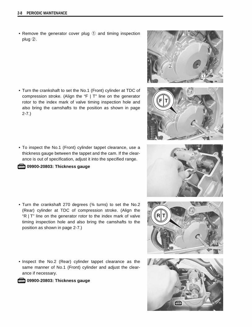
• Remove the generator cover plug
1 and timing inspectionplug
2.
• Turn the crankshaft to set the No.1 (Front) cylinder at TDC ofcompression stroke. (Align the “F | T” line on the generatorrotor to the index mark of valve timing inspection hole andalso bring the camshafts to the position as shown in page2-7.)
• To inspect the No.1 (Front) cylinder tappet clearance, use athickness gauge between the tappet and the cam. If the clear-ance is out of specification, adjust it into the specified range.
$ 09900-20803: Thickness gauge
• Turn the crankshaft 270 degrees (¾ turns) to set the No.2(Rear) cylinder at TDC of compression stroke. (Align the“R | T” line on the generator rotor to the index mark of valvetiming inspection hole and also bring the camshafts to theposition as shown in page 2-7.)
• Inspect the No.2 (Rear) cylinder tappet clearance as thesame manner of No.1 (Front) cylinder and adjust the clear-ance if necessary.
$ 09900-20803: Thickness gauge
F T
RR TTR T
PERIODIC MAINTENANCE 2-9
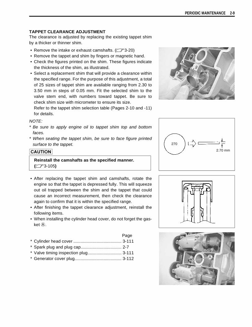
TAPPET CLEARANCE ADJUSTMENTThe clearance is adjusted by replacing the existing tappet shimby a thicker or thinner shim.
• Remove the intake or exhaust camshafts. (!3-20)• Remove the tappet and shim by fingers or magnetic hand.• Check the figures printed on the shim. These figures indicate
the thickness of the shim, as illustrated.• Select a replacement shim that will provide a clearance within
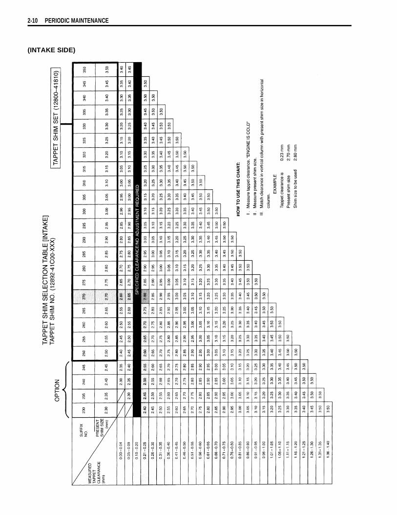
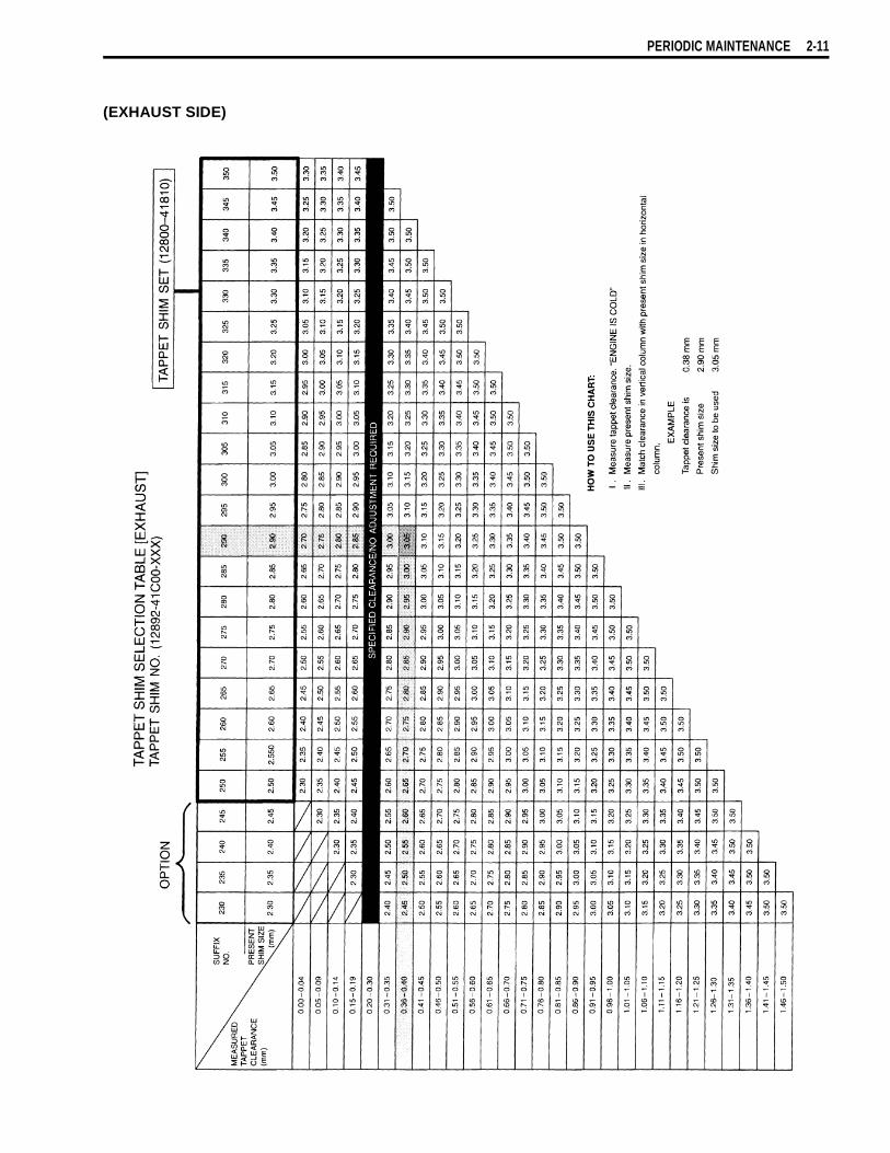
the specified range. For the purpose of this adjustment, a totalof 25 sizes of tappet shim are available ranging from 2.30 to3.50 mm in steps of 0.05 mm. Fit the selected shim to thevalve stem end, with numbers toward tappet. Be sure tocheck shim size with micrometer to ensure its size.Refer to the tappet shim selection table (Pages 2-10 and -11)for details.
NOTE:* Be sure to apply engine oil to tappet shim top and bottom
faces.* When seating the tappet shim, be sure to face figure printed
surface to the tappet.
"
• After replacing the tappet shim and camshafts, rotate theengine so that the tappet is depressed fully. This will squeezeout oil trapped between the shim and the tappet that couldcause an incorrect measurement, then check the clearanceagain to confirm that it is within the specified range.
• After finishing the tappet clearance adjustment, reinstall thefollowing items.
• When installing the cylinder head cover, do not forget the gas-ket
A.
Page* Cylinder head cover ........................................ 3-111* Spark plug and plug cap.................................. 2-7* Valve timing inspection plug............................ 3-111* Generator cover plug....................................... 3-112
Reinstall the camshafts as the specified manner.(!3-105)
270
2.70 mm
2-10 PERIODIC MAINTENANCE
(INTAKE SIDE)
PERIODIC MAINTENANCE 2-11
(EXHAUST SIDE)
2-12 PERIODIC MAINTENANCE
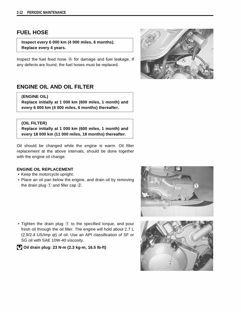
FUEL HOSE
Inspect the fuel feed hose
A for damage and fuel leakage. Ifany defects are found, the fuel hoses must be replaced.
ENGINE OIL AND OIL FILTER
Oil should be changed while the engine is warm. Oil filterreplacement at the above intervals, should be done togetherwith the engine oil change.
ENGINE OIL REPLACEMENT• Keep the motorcycle upright.• Place an oil pan below the engine, and drain oil by removing
the drain plug
1 and filler cap
2.
• Tighten the drain plug
1 to the specified torque, and pourfresh oil through the oil filler. The engine will hold about 2.7 L(2.9/2.4 US/Imp qt) of oil. Use an API classification of SF orSG oil with SAE 10W-40 viscosity.
& Oil drain plug: 23 N·m (2.3 kg-m, 16.5 lb-ft)
Inspect every 6 000 km (4 000 miles, 6 months).Replace every 4 years.
(ENGINE OIL)Replace initially at 1 000 km (600 miles, 1 month) andevery 6 000 km (4 000 miles, 6 months) thereafter.
(OIL FILTER)Replace initially at 1 000 km (600 miles, 1 month) andevery 18 000 km (11 000 miles, 18 months) thereafter.
PERIODIC MAINTENANCE 2-13
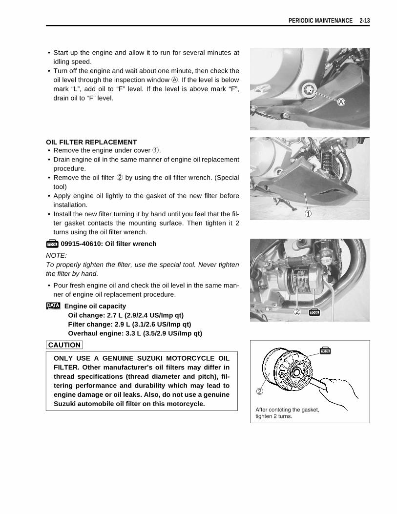
• Start up the engine and allow it to run for several minutes atidling speed.
• Turn off the engine and wait about one minute, then check theoil level through the inspection window
A. If the level is belowmark “L”, add oil to “F” level. If the level is above mark “F”,drain oil to “F” level.
OIL FILTER REPLACEMENT• Remove the engine under cover
1.• Drain engine oil in the same manner of engine oil replacement
procedure.• Remove the oil filter
2 by using the oil filter wrench. (Specialtool)
• Apply engine oil lightly to the gasket of the new filter beforeinstallation.
• Install the new filter turning it by hand until you feel that the fil-ter gasket contacts the mounting surface. Then tighten it 2turns using the oil filter wrench.
$ 09915-40610: Oil filter wrench
NOTE:To properly tighten the filter, use the special tool. Never tightenthe filter by hand.
• Pour fresh engine oil and check the oil level in the same man-ner of engine oil replacement procedure.
% Engine oil capacity Oil change: 2.7 L (2.9/2.4 US/Imp qt)Filter change: 2.9 L (3.1/2.6 US/Imp qt)Overhaul engine: 3.3 L (3.5/2.9 US/Imp qt)
"ONLY USE A GENUINE SUZUKI MOTORCYCLE OILFILTER. Other manufacturer’s oil filters may differ inthread specifications (thread diameter and pitch), fil-tering performance and durability which may lead toengine damage or oil leaks. Also, do not use a genuineSuzuki automobile oil filter on this motorcycle.
After contcting the gasket,tighten 2 turns.