Embed Size (px)
Citation preview
SustainableEnergy & Fuels
PAPER
Ope
n A
cces
s A
rtic
le. P
ublis
hed
on 0
8 A
ugus
t 201
7. D
ownl
oade
d on
10/
30/2
021
9:43
:23
PM.
Thi
s ar
ticle
is li
cens
ed u
nder
a C
reat
ive
Com
mon
s A
ttrib
utio
n 3.
0 U
npor
ted
Lic
ence
.
View Article OnlineView Journal | View Issue
Process explorat
Department of Chemical Engineering, Imperi
E-mail: [email protected]
† Electronic supplementary informa10.1039/c7se00206h
Cite this: Sustainable Energy Fuels,2017, 1, 1541
Received 19th April 2017Accepted 20th June 2017
DOI: 10.1039/c7se00206h
rsc.li/sustainable-energy
This journal is © The Royal Society of C
ion and assessment for theproduction of methanol and dimethyl ether fromcarbon dioxide and water†
A. Hankin * and N. Shah
A thermodynamic, model-based, study was carried out to assess the relative performance of methanol and
dimethyl ether (DME) synthesis systems using CO- and CO2-based syngas feeds. The upstream production
of a range of syngas feed compositions was simulated using CO2 and H2O as the sole chemical building
blocks, a requirement motivated by the increasing constraints on permissible CO2 emissions and the
successful adaptation by some industrial methanol plants to the direct utilisation of CO2. The objective
was to establish whether the energy requirements and CO2 emissions associated with upstream
conversion of CO2 to CO were justified by increased productivity in the methanol/DME systems. In the
first part of the study, the performance of four systems was evaluated and compared in terms of energy
efficiency and CO2 conversion: (1) methanol synthesis system, (2) direct DME synthesis system, (3) two-
step DME synthesis system with an interposed syngas separation step between the methanol production
reactor and methanol dehydration reactor and (4) two-step DME synthesis system with no separation
step between the two reactors. Based on equilibrium yields at 250 �C and 50 bar, the direct DME
synthesis system was found to exhibit the highest energy conversion efficiencies with both CO2- and
CO-based syngas. Although this system demonstrated the lowest CO2 emissions per methanol
equivalent product with a CO-based feed, the benefits were offset by emissions associated with the
upstream conversion of H2O and CO2 to H2 and CO, evaluated in the second part of the study. It was
determined that CO2 could be utilised directly in the direct DME synthesis route, whereas upstream
conversion of CO2 to CO was necessary to achieve effective yields in the methanol/two-step DME
systems. CO-based syngas production via high temperature co-electrolysis of H2O and CO2, or
alternatively high temperature CO2 electrolysis coupled with the water–gas shift process, was identified
as the best technology based on energy consumption and CO2 utilisation.
Introduction
Presently, dense energy carriers with applications in energystorage, such as methanol and dimethyl ether (DME) are, foreconomic reasons, derived principally from fossil fuels.1 Typi-cally, syngas is rst generated from either natural gas or coaland subsequently converted to methanol, DME or other liquidhydrocarbons via the Fischer–Tropsch process. These processesrelease CO2. For example, conventional methanol productionplants can release over 5 t(CO2)/t(methanol),2 depending on thefeedstock. However, emissions of CO2 and other greenhousegases (GHG) into the atmosphere are becoming a globalconcern and regulations requiring their minimisation are beingput in place.3 One of the consequences will be the gradualdecarbonisation of energy sources, which is expected to
al College London, London, SW7 2AZ, UK.
tion (ESI) available. See DOI:
hemistry 2017
decrease the overall demand for coal and gas.4 Consequently,alternative choices of raw materials, as well as the re-design ofprocesses that would enable the minimisation of CO2 emis-sions, are required. Indeed this is the basis for the concept ofthe methanol economy,5 in which CO2 is recycled into methanoland DME for energy storage or conversion to other syntheticfuels in order to reduce dependence on fossil fuels and tomitigate the rate of global warming.
Investigation of direct and indirect utilisation of CO2 inmethanol and DME synthesis processes was the focus of thisstudy because of their industrial importance and large scaleproduction.1 Methanol is used in the manufacture of chemicals,such as formaldehyde, methyl tert-butyl ether (MTBE) and ace-tic acid, as well as plastics. It can be transformed into petro-chemicals or blended with them for use in internal combustionengines;6 it can also be used in fuel cells.7 DME, the dehydrationproduct of methanol, is a non-toxic chemical with uses inhousehold products, aerosol propellants, paints and, likemethanol, can be used as a fuel either directly or in a blend,7,8
for example with liqueed petroleum gas (LPG). DME has
Sustainable Energy Fuels, 2017, 1, 1541–1556 | 1541

Sustainable Energy & Fuels Paper
Ope
n A
cces
s A
rtic
le. P
ublis
hed
on 0
8 A
ugus
t 201
7. D
ownl
oade
d on
10/
30/2
021
9:43
:23
PM.
Thi
s ar
ticle
is li
cens
ed u
nder
a C
reat
ive
Com
mon
s A
ttrib
utio
n 3.
0 U
npor
ted
Lic
ence
.View Article Online
already replaced diesel fuel in the engines of some vehicles,demonstrating improved environmental performance.9,10 Theadvantage of both methanol and dimethyl ether is that they donot generate carbonaceous particulate matter uponcombustion.
Encouragingly, several projects have now demonstrated thatmethanol can be synthesized directly from CO2 captured fromlarge point sources, such as power plants, and H2 generatedelectrochemically from H2O.11–14 These processes utilise modi-ed catalysts with greater tolerance to water build-up and alsolarger fractions of hydrogen to carbon in the system feeds thanthose used in conventional processes.
The feasibility of direct CO2 utilisation on an industrial scaleconrms that the widely reported problems associated withslow CO2 dehydrogenation kinetics and catalyst deactivation aresurmountable. Hence, the purpose of this study was to re-examine and compare the thermodynamic constraints onmethanol as well as DME syntheses from CO- and CO2-basedsyngas using system analysis in Aspen Plus V8.8. The goal was toidentify the theoretical differences between system efficiencieswhen CO and CO2 were the principal sources of carbon to thesynthesis steps and whether in certain situations a CO2-basedfeed could be preferable to a CO-based one. Equilibrium syngasconversion was investigated in four systems:
1. Methanol synthesis;2. Direct DME synthesis (methanol dehydration occurring
simultaneously with CO/CO2 hydrogenation);3. Two-step DME synthesis (methanol synthesis and meth-
anol dehydration occurring in two separate stages) with aninterposed unreacted syngas separation step;
4. Two-step DME synthesis with no separation step betweenthe two reactors.
In the rst part of the study, system efficiencies and extentsof CO2 conversion were examined for Stage 2 in Fig. 1 asa function of hydrogen to total carbon molar ratios, H2 : (CO2 +CO), in the system feed. The total molar carbon ux : (CO2 + CO)was xed, while the CO2 : CO ratio was varied between 1 andz0in order to determine the theoretical limitations imposed whenCO2 rather than CO was supplied to the conversion systems.Efficiencies were evaluated as quotients of the net energiesproduced in Stage 2 and the energies contained in the syngasentering Stage 2. Net energies were computed based on energies
Fig. 1 Principal stages in methanol and DME syntheses from CO2 andH2O. In Stage 1, CO2 and H2O are converted to CO and H2 (syngas); incases where CO2 it utilised directly only H2 is generated in Stage 1. InStage 2, syngas is converted to methanol and/or DME.
1542 | Sustainable Energy Fuels, 2017, 1, 1541–1556
extracted in the form of methanol and DME and energiesrequired to support the operation of heaters, compressors anddistillation columns in the systems. The energy contained in thesyngas was based on the lower heating values of hydrogen andcarbon monoxide. Various energy saving mechanisms wereexamined, including the combustion of vented gases and thecoupling of heat exchangers.
In the second part of the study, possible routes to syngascompositions identied as optimum for Stage 2 were explored.Energy requirements were estimated and compared against thebenets of utilising CO over CO2 in Stage 2. DecontaminatedCO2 and H2O were assumed to be the sole building blocks forsyngas generation in Stage 1, as shown in Fig. 1, hencerespecting the system boundary.
Potential disparities between thermodynamic predictionsand kinetics were not considered in this study because thebroad range of feed compositions under investigation here hasnot been covered by a complete set of kinetic data and becausethe wide range of kinetic data available for different catalystscannot be readily distilled to parameters applicable across thewhole range of syngas compositions.
Industrial processes
The chemical reactions and process layouts for methanol andDME synthesis, as well as examples of industrial processes, aredescribed below.
Industrial production of methanol and dimethyl ether
Methanol production from syngas. Methanol is principallyformed by the hydrogenation of CO (1) but can also be synthe-sized by hydrogenation of CO2 (2). The water gas shi reaction(WGS) (3) takes place simultaneously with (1) and (2). Copperbased catalysts such as Cu/ZnO, employed most commonly,catalyse all three processes.11,13,15
A general process layout for industrial methanol productionis shown in Fig. 2. Fresh syngas in fed into a methanol reactor,which is operated at temperatures in the range of 150–300 �Cand under pressures in the range 10–100 bar,11 although typical
Fig. 2 A general process layout for a commercial methanol produc-tion system.
This journal is © The Royal Society of Chemistry 2017

Paper Sustainable Energy & Fuels
Ope
n A
cces
s A
rtic
le. P
ublis
hed
on 0
8 A
ugus
t 201
7. D
ownl
oade
d on
10/
30/2
021
9:43
:23
PM.
Thi
s ar
ticle
is li
cens
ed u
nder
a C
reat
ive
Com
mon
s A
ttrib
utio
n 3.
0 U
npor
ted
Lic
ence
.View Article Online
conditions are 250–260 �C and 50–60 bar. A large number ofreactor designs have been commercialised, but generally theseare operated either under adiabatic or isothermal conditions.7
In both reactor types, the control of reactor temperatures is oneof the principal challenges because reactions (1)–(3) areexothermic and can cause temperatures to rise above 300 �C, atwhich catalyst deactivation oen occurs.1
CO + 2H2 % CH3OH (1)
CO2 + 3H2 % CH3OH + H2O (2)
COþH2O ������! ������WGS
RWGSCO2 þH2 (3)
The reactor effluent, which contains methanol, water andunreacted syngas is cooled to condense out the methanol, waterand any absorbed CO2. Methanol is generally separated bydistillation.11 Aer separation from methanol and water, theunreacted gases may be processed further, for example toremove the CO2, and then recycled into the reactor. CO2 is thenvented or recycled further upstream.
Although CO2 is reported to have an adverse effect onmethanol synthesis rates, studies with isotopic labelling16 ona commercial Cu/ZnO/Al2O3 catalyst showed that in facta certain quantity of CO2 in the syngas (4–8%) is essential tomake conversion to methanol possible as CO2 is the principalsource of carbon in the methanol7,17 and also to protect catalystsfrom deactivation.18
There are presently three industrial methanol synthesisplants that exclusively utilise CO2 and H2. Mitsui Chemicals'Osaka Works combines puried CO2 exhaust with H2 producedby water electrolysis to generate methanol.11 Catalysts able totolerate high water levels, caused by reaction (2) and the reversewater gas shi reaction (3) (RWGS), were specically developedfor these conditions. CO2 was not removed from the recycleloop, while a portion of the unreacted gases was combusted tosupply heat to other parts of the system.
Carbon Recycling International (CRI) produces 4000 t peryear of renewable methanol (Vulcanol™) by direct synthesisusing carbon dioxide, sourced from ue gas released bya geothermal power plant, and hydrogen, generated fromrenewably powered water electrolysis.12 This process is reportedto reduce carbon emissions by more than 85% compared withplants that utilise syngas derived from fossil fuels.19 The meth-anol is subsequently blended with gasoline to power cars. Twomethods are potentially used to achieve CO2 and H2 conversion.In the rst method, the CO2 and H2, undergo the RWGS reac-tion;20 following the removal of water from the product stream bycondensation, and separation of CO2 by isothermal compres-sion, hydrogen is added to the remaining product stream toachieve the ratio H2 : CO of 2 : 1, before being fed into themethanol reactor. In the second method, H2 and CO2, in a ratioof 7 : 2, are reacted directly to form methanol and CO.
Blue Fuel Energy is amongst the next producers of renewablemethanol from captured CO2 and H2 produced in an electro-lyser powered by renewables, and to convert it to gasoline.14 Net
This journal is © The Royal Society of Chemistry 2017
greenhouse gas (GHG) emissions are expected to be heavilyinuenced by the H2 production process;21 however, prelimi-nary gures suggest a reduction in CO2 emissions by 65–84%relative to fossil fuel based processes.19
In terms of capital investment, methanol synthesis from CO2
and H2 has been estimated to be approximately the same as thatfor a conventional plant.1 The principal limiting factor for scale-up of such processes is said to be the availability and price ofCO2 and H2 and the source of electrical energy.
The systems reported to date use a range of H2 : carbonratios, depending on whether CO or CO2 is used in the feed. Astoichiometric ratio of 2, as dened by eqn (4), is preferred forsyngas with high CO : CO2 ratios.
SR ¼ ðH2 � CO2ÞðCOþ CO2Þ (4)
However, oen for kinetic reasons a value slightly higherthan 2 is employed in industry. For example, the isothermalLurgi Methanol Converter uses SR ¼ 2.05–2.1;22 Haldor Topsoeuse SR ¼ 2. On the other hand, for processes employing directconversion of CO2 and H2 to methanol, a ratio of 3.5 was used13
and a ratio of 5.0 was specied as optimum.11 The higher than 2ratio is designed to decrease the molar fraction of water so as tolimit its adsorption onto the catalyst. In this way, the decreasein the methanol production efficiency can be mitigated. One ofthe objectives of this study was to identify the optimum ther-modynamic H2 : CO2 ratios in the system feeds when CO2 wasutilised directly for the production of methanol/DME.
Dimethyl ether production from syngas. Dimethyl ether isproduced via the dehydration of methanol by reaction (5) oversolid acid catalysts such as gamma alumina (g-Al2O3), silicaalumina, activated alumina or ZSM-5 (zeolite-based cata-lysts).23,24 This process requires temperatures and pressures inthe ranges of 210–290 �C and 30–100 bar, respectively, andhence is wholly compatible with methanol productionconditions.
2CH3OH 5 CH3OCH3 + H2O (5)
Reaction (5) can take place in a designated reactor, intowhich methanol, produced in a separate reactor via (1), (3) and/or (2), is fed. Alternatively, both the production and dehydrationof methanol can take place in the same reactor that utilises bi-functional catalysts, such as Cu/ZnO/g-Al2O3. The former andthe latter production methods are commonly referred to as the‘two-step process’ and direct ‘one-step process’, respectively.
If only CO and H2 are present in the reactor system feed, theoverall reaction is:
3CO + 3H2 % CH3OCH3 + CO2 (6)
The stoichiometric requirement for the H2 : CO ratio in thefeed is 1 : 1. Notably, this process will result in the generation ofCO2. This drawback could be resolved by recycling and usingCO2 in the process by which syngas is produced, be it drymethane reforming or reduction to CO in high temperature
Sustainable Energy Fuels, 2017, 1, 1541–1556 | 1543

Fig. 3 Equilibrium CO2 conversion in the direct DME process (no�
Sustainable Energy & Fuels Paper
Ope
n A
cces
s A
rtic
le. P
ublis
hed
on 0
8 A
ugus
t 201
7. D
ownl
oade
d on
10/
30/2
021
9:43
:23
PM.
Thi
s ar
ticle
is li
cens
ed u
nder
a C
reat
ive
Com
mon
s A
ttrib
utio
n 3.
0 U
npor
ted
Lic
ence
.View Article Online
solid oxide electrolysers. However, in terms of CO2 emissions,the preferred option would be to minimise the generation ofCO2, such that separation and recycle costs could beminimised,and that the DME production process would always result in netCO2 utilisation. If CO2 is present in the system feed togetherwith CO and H2, the overall process reaction becomes:
2CO + 4H2 % CH3OCH3 + H2O (7)
Hence, net CO2 production by the reactor could be mini-mised, provided the ratio of CO2 : CO : H2 in the system feed isoptimised in order for thermodynamics and kinetics to befavourable.
An additional issue is the generation of water by reactions (5)and (7), resulting in CO2 and H2 production by the WGS reac-tion (3). While H2 is benecial for CO conversion via reaction(1), the production of CO2 is not and serves to reverse thebenets of reaction (2). If one of the principal goals is CO2
mitigation, then the constraints on the process must includethe requirement that less CO2 is produced than is consumed.Therefore, this places a lower limit on the H2 : (CO2 + CO) ratiothat can be used in the system feed. The degree of syngasconversion and CO2 emissions depend greatly on the type ofprocess used: there are two principal options.
Two-step process. The two-step process is the moreconventional method for DME production and is currentlyemployed by companies such as Haldor Topsoe, Toyo Engi-neering (TEC), Oberon Fuels, BioDME and Lurgi (Air Products).With this approach, a methanol dehydration reactor, typicallya xed bed catalytic system, may be connected to an existingmethanol production facility and used when required.Furthermore, the separate dehydration step is reported torequire low capital investment, provided there is high feedstockavailability. The maturity of the available technology forobtaining methanol and the relative simplicity of methanoldehydration are the great attractions of the two-step process.Furthermore, the limited activity of the solid acid dehydrationcatalysts for the water gas shi reaction at low temperaturesresults in only small amounts of CO2 generated by reaction (3)in the second step; the same is not true for the one-step system,where the catalyst used for converting syngas to methanol alsohas a high activity for the WGS reaction.
One-step process. A higher syngas conversion and molarmethanol equivalent productivity (MEP), dened in eqn (8),25
can theoretically be achieved in the direct process compared tothe two-step process:
MEP ¼ [MeOH] + 2[DME] (8)
Productivity is improved in the one-step system because insitu dehydration of methanol displaces the equilibrium in eqn(1) and (2); hence, methanol yields and, consequently, DMEyields increase. Due to the synergy between reactions (1)–(3) and(5), syngas conversion to DME gives higher equilibriumconversions than syngas conversion to methanol.7 Industrialfeasibility studies have already been carried out,26 where severalcompanies tested a 100 t(DME) d
�1 demonstration plant, which
1544 | Sustainable Energy Fuels, 2017, 1, 1541–1556
accomplished a 96% synthesis gas (H2 : CO ¼ 1.0, derived fromnatural gas) conversion to DME. However, since the 2006 reportof isolated tests, no large scale production of DME by the directprocess is taking place.
Improvement of the methanol equivalent productivity by theone-step DME process over the methanol process has also beendemonstrated both experimentally (250 �C and 52 bar) andnumerically25,27 by academic research. However, becausea mixture of DME and CO2 is formed in the one-step process,more downstream separation technologies will be required withthis method than with the two-step process because of the highdegree of association of the two molecules.28 Concurrent DMEand CO2 separation from unreacted syngas will be necessary ifthe reactor operates with a H2 : CO mixture. For example, DMEand CO2 can be removed simultaneously with a scrubbingsolvent of methanol and DME;28 subsequently further process-ing to separate DME from CO2 and recover the solvent isrequired. However, DME separation becomes more straight-forward if the reactor is able to process CO2 and hence CO2 canremain in the recycle loop. Separation of DME alone may beaccomplished with water as the scrubbing solvent23 and a ashseparator. Consequently, recovery of DME alone will havea lesser effect on the overall energy efficiency of the process.
It is imperative to quantify the CO2 output from a givensystem. For example, in the one-step process the formation ofwater by reaction (5) results in more CO2 being produced thanconsumed. This point is evident in Fig. 3, which shows per-passconversion of CO2 and where negative conversion signies CO2
formation. CO2 production increases with the proportion of COin the system feed. Consequently, operating conditions must beidentied where energy efficiency is maximised while CO2
emissions are minimised. Additionally, CO2 may be recycled.A further drawback of the one-step system is that, in practice,
catalyst activity may become inhibited by water build-up from
recycle) at 250 C and 50 bar.
This journal is © The Royal Society of Chemistry 2017
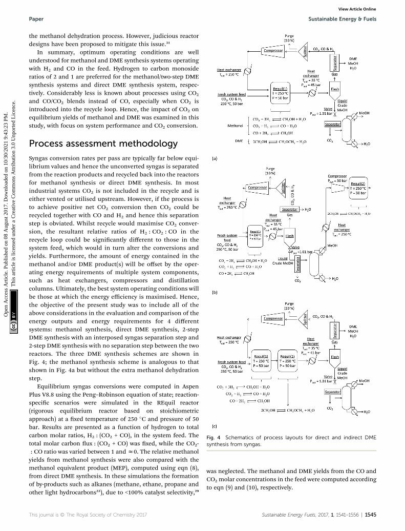
Fig. 4 Schematics of process layouts for direct and indirect DMEsynthesis from syngas.
Paper Sustainable Energy & Fuels
Ope
n A
cces
s A
rtic
le. P
ublis
hed
on 0
8 A
ugus
t 201
7. D
ownl
oade
d on
10/
30/2
021
9:43
:23
PM.
Thi
s ar
ticle
is li
cens
ed u
nder
a C
reat
ive
Com
mon
s A
ttrib
utio
n 3.
0 U
npor
ted
Lic
ence
.View Article Online
the methanol dehydration process. However, judicious reactordesigns have been proposed to mitigate this issue.31
In summary, optimum operating conditions are wellunderstood for methanol and DME synthesis systems operatingwith H2 and CO in the feed. Hydrogen to carbon monoxideratios of 2 and 1 are preferred for the methanol/two-step DMEsynthesis systems and direct DME synthesis system, respec-tively. Considerably less is known about processes using CO2
and CO/CO2 blends instead of CO, especially when CO2 isintroduced into the recycle loop. Hence, the impact of CO2 onequilibrium yields of methanol and DME was examined in thisstudy, with focus on system performance and CO2 conversion.
Process assessment methodology
Syngas conversion rates per pass are typically far below equi-librium values and hence the unconverted syngas is separatedfrom the reaction products and recycled back into the reactorsfor methanol synthesis or direct DME synthesis. In mostindustrial systems CO2 is not included in the recycle and iseither vented or utilised upstream. However, if the process isto achieve positive net CO2 conversion then CO2 could berecycled together with CO and H2 and hence this separationstep is obviated. Whilst recycle would maximise CO2 conver-sion, the resultant relative ratios of H2 : CO2 : CO in therecycle loop could be signicantly different to those in thesystem feed, which would in turn alter the conversions andyields. Furthermore, the amount of energy contained in themethanol and/or DME product(s) will be offset by the oper-ating energy requirements of multiple system components,such as heat exchangers, compressors and distillationcolumns. Ultimately, the best system operating conditions willbe those at which the energy efficiency is maximised. Hence,the objective of the present study was to include all of theabove considerations in the evaluation and comparison of theenergy outputs and energy requirements for 4 differentsystems: methanol synthesis, direct DME synthesis, 2-stepDME synthesis with an interposed syngas separation step and2-step DME synthesis with no separation step between the tworeactors. The three DME synthesis schemes are shown inFig. 4; the methanol synthesis scheme is analogous to thatshown in Fig. 4a but without the extra methanol dehydrationstep.
Equilibrium syngas conversions were computed in AspenPlus V8.8 using the Peng–Robinson equation of state; reaction-specic scenarios were simulated in the REquil reactor(rigorous equilibrium reactor based on stoichiometricapproach) at a xed temperature of 250 �C and pressure of 50bar. Results are presented as a function of hydrogen to totalcarbon molar ratios, H2 : (CO2 + CO), in the system feed. Thetotal molar carbon ux : (CO2 + CO) was xed, while the CO2-: CO ratio was varied between 1 andz0. The relative methanolyields from methanol synthesis were also compared with themethanol equivalent product (MEP), computed using eqn (8),from direct DME synthesis. In these simulations the formationof by-products such as alkanes (methane, ethane, propane andother light hydrocarbons23), due to <100% catalyst selectivity,29
This journal is © The Royal Society of Chemistry 2017
was neglected. The methanol and DME yields from the CO andCO2 molar concentrations in the feed were computed accordingto eqn (9) and (10), respectively.
Sustainable Energy Fuels, 2017, 1, 1541–1556 | 1545

Fig. 5 Schematic illustration of the two simulated energy savingmethods in a given recycle loop. In the first energy saving method,heat is recovered from the post-reactor gas stream by a cold pres-surised water stream and subsequently delivered to the cold gasstream in the recycle loop. In the second energy saving method thepurged H2 and CO gases are combusted and a fraction of the energy isrecovered as heat and/or work and delivered to the heat exchangerand compressor, respectively, in the recycle loop.
Sustainable Energy & Fuels Paper
Ope
n A
cces
s A
rtic
le. P
ublis
hed
on 0
8 A
ugus
t 201
7. D
ownl
oade
d on
10/
30/2
021
9:43
:23
PM.
Thi
s ar
ticle
is li
cens
ed u
nder
a C
reat
ive
Com
mon
s A
ttrib
utio
n 3.
0 U
npor
ted
Lic
ence
.View Article Online
hMeOH ¼½MeOH�out�½CO2� þ ½CO�
�in
(9)
hDME ¼2� ½DME�out�½CO2� þ ½CO�
�in
(10)
System streams
In all systems fresh syngas entered the rst reactor pre-heatedand pre-pressurized. In the methanol system and in systems(a) and (b) the output streams from the rst reactor were cooledin heat exchangers and condensed in ash columns. In system(c) the product stream from the rst reactor underwent furtherconversion in the second reactor before being cooled andpassed through a condenser. In system (b) the liquid streamfrom the ash column containing principally methanol, waterand a small molar fraction of CO2 was expanded to atmosphericpressure in a valve and processed in a distillation column inorder to obtain a concentrated liquid methanol stream. Themethanol was then re-heated, re-pressurised and dehydrated toDME. In all systems a 5 bar pressure drop in the recycle loopswas assumed.30
In all four systems, 90% of the unreacted syngas from theash column was re-pressurised to 50 bar, re-heated to matchthe temperature and pressure of the fresh syngas and recircu-lated back into the rst reactor. The remaining 10% was purgedto avoid build-up of unreacted gas components. In systems (a)and (b) the DME was removed from the unreacted gases usingidealised separators. In practice, DME removal could be ach-ieved using a scrubbing solvent such as water.23 Energyrequirements for this step were not considered explicitly in thisstudy. Neither the separation of the three syngas componentsfrom each other to enable the adjustment of their ratios in therecycle loop nor the addition of specic gases to the recycle loopwas considered. Hence, the gas ratios in the reactor feed weretypically different to those in the system feed.
Reactors
The reactors were assumed to operate under isothermalconditions. In practice the syngas temperature at the inlet is setto be tens of degrees lower than the reactor temperature31
because the heat released by the exothermic reactions (1)–(3)and (5) can cause signicant and undesirable temperaturegradients inside the reactors and result in catalyst deactivation.However, the temperature proles are highly specic to theconvective effects/cooling mechanisms employed in differentreactor designs and hence in this study the inlet gas tempera-tures were matched to the reactor temperatures, resulting inslight overestimation of heater duties.
Energy efficiency analysis
There were three levels in the analyses of system energyrequirements: in the rst, the heater and compressor energyrequirements were met entirely by external means and wereassociated with additional CO2 emissions; in the second, thepre-ash column heat exchangers were coupled with the recycleloop heat exchangers via a water stream to generate an energy
1546 | Sustainable Energy Fuels, 2017, 1, 1541–1556
saving; nally, combustion of the H2 and CO gases in the purgestream to meet a fraction of the compressor and heat exchangerenergy requirements was considered as an option. Thecomplete conversion of the purged H2 and CO to either heat orelectrical energy was assumed to allow the utilisation of ca. 60%of the combustion energy, based on their respective lowerheating values (237 kJ mol�1 for H2 and 283 kJ mol�1 for CO32).These additional considerations are shown schematically inFig. 5.
Compressors, pumps, heat exchangers and distillationcolumns
The gas compressors were assumed to operate with an isen-tropic efficiency of 90% and amechanical efficiency of 90%. Thewater stream by which the heat exchangers were coupled hadinitial temperature and pressure of 20 �C and 1 atmosphererespectively, and was pressurized with a pump assumed tooperate with 70% energy efficiency to 40 bar prior to entry intothe rst heat exchanger. This water stream was constrained toa liquid state (Tsat ¼ 250 �C at 40 bar) at all stages. Additionalheat exchangers were added to the recycle loop to ensure therecycled gas stream was pre-heated to 250 �C, prior to re-entryinto the rst reactor.
DSTWU distillation columns in Aspen Plus, utilising Gilli-land's, Winn's, and Underwood's methods were used to modelmethanol separation from water by computing the requirednumber of stages and reux ratios for each scenario. Idealisedseparators were employed for removing CO2 and any minutefractions of CO and H2 from the liquid crude methanol streamprior to entry into the distillation units.
Not taken into account were the energy requirement and CO2
emissions associated with the supply of the air/O2 that would berequired to support CO and H2 combustion. Furthermore, the
This journal is © The Royal Society of Chemistry 2017

Paper Sustainable Energy & Fuels
Ope
n A
cces
s A
rtic
le. P
ublis
hed
on 0
8 A
ugus
t 201
7. D
ownl
oade
d on
10/
30/2
021
9:43
:23
PM.
Thi
s ar
ticle
is li
cens
ed u
nder
a C
reat
ive
Com
mon
s A
ttrib
utio
n 3.
0 U
npor
ted
Lic
ence
.View Article Online
energy required to pressurise and heat the fresh feed gases tothe system were not included and are part of a separate analysisthat addresses the mechanisms of syngas production.
CO2 emissions
The power demand and CO2 emissions associated with the heatexchangers as well as with the compressors, the water pumpand the reboiler and condenser in the distillation columns werecomputed and taken into account in the energy balance,assuming emissions of 5.4 kg(CO2) GJ
�1.33 In practice, the gasescan either undergo homogenous combustion, for which thecombustion temperature would need to exceed the auto-ignition temperatures of both H2 (500 �C) and CO (609 �C)34
or alternatively direct conversion to electrical energy in fuelcells. CO2 emissions resulting from complete combustion of thepurged CO have also been taken into account; combustion of H2
does not generate CO2 as the product is only water vapour.
Fig. 6 MEP increase of the direct DME process relative to methanolalone; calculations based on reactor outputs at 250 �C and 50 bar inthe absence of recycle.
Results and discussionEquilibrium yields without recycle
Although calculations for equilibrium yields have been performedpreviously for both methanol and DME synthesis,25 and areconclusive about the optimummolar proportions of H2 and CO inthe reactor feed, it is benecial to perform these calculations withthe additional inclusion of CO2 in order to understand thedifferent choices of feed compositions used industrially, especiallywhere CO2 is the principal source of carbon. Hence, initially theper-pass equilibrium yields of methanol and DME, their molarfractions in the reactor product streams, the extents of H2, CO2 andCO conversion, as well as the molar fractions of the water by-product are shown in Fig. 1S–4S in the (ESI†).
Fig. 1S(a)† shows that in the case of methanol synthesis, theprocess output is much more sensitive to the H2 : CO ratio thanit is to the H2 : CO2 ratio. As shown previously,25 a process uti-lising principally H2 and CO in the feed exhibits optimumperformance in terms of the methanol molar fraction in theproduct stream at the stoichiometric H2 : CO ratio of z2. Athigher H2 to carbon ratios, the conversion of CO2 and CO tomethanol continues to increase with a decreasing slope (sub-Fig. 1S(c) and (d)†), but at the expense of lower hydrogenconversion (Fig. 1S(e)†). Hence, the choice of whether to operateunder hydrogen rich conditions will be dictated by the cost ofhydrogen production and energy consumption of methanolseparation. However, hydrogen-rich conditions can promote theformation of water, especially when CO2 is the main source ofcarbon, and this places signicant constraints on the choice ofcatalyst. Water production by the reverse water gas shi reac-tion increases substantially with CO2 fraction in the syngasfeed, passing through a maximum at H2 : CO2 of approximately2, but subsequently decreasing (Fig. 1S(f)†). The decay in themolar fraction of the water by-product under hydrogen richconditions for a H2–CO2 feed justies the choice of higherH2 : CO2 ratios employed industrially.11,13 Consequently, forsystems utilising primarily CO and H2, stoichiometric feedcompositions give the optimum yield, while for systems using
This journal is © The Royal Society of Chemistry 2017
primarily CO2 and H2, higher CO2 conversion can be achievedunder hydrogen-rich conditions, provided the hydrogen can besourced sufficiently cheaply and the chosen catalyst can toleratewater build-up. However, even if CO2 is the sole source ofcarbon in the system feed, in the presence of a recycle loop,a certain quantity of carbon monoxide will be present in thereactor feed as it is formed via the reverse water gas shi reac-tion in parallel with methanol synthesis.
If methanol dehydration can proceed simultaneously withCO2 and CO hydrogenation, the methanol equivalent product(MEP) is greater than in the case of methanol, as shown inFig. 6. The advantage is especially apparent when H2 : (CO2 +CO) < 1. However, for the various CO2 : CO ratios it is apparentthat the greatest advantage of the additional dehydration stepcan be gained when CO2 is the principal source of carbon. Fora syngas feed without CO2, the maximum DME molar fractionin the product is found at a H2 : CO ratio of 1, which corre-sponds to a more carbon rich regime relative to methanol alone(Fig. 2S(a)) in the (ESI†). Under this condition, the build-up ofwater is minimised by the water gas shi reaction but at theexpense of carbon dioxide formation, as is evident fromFig. 2S(c).†Hence, if the CO in the syngas is produced from CO2
in Stage 1 (Fig. 1), then it would be impractical to reverse thebenets of further conversion to fuel in Stage 2 by selectingconditions that would re-generate the CO2 to the greatestdegree. Fig. 7 shows the extents of CO to CO2 conversion in themethanol and direct DME processes when a H2–CO only feed isused, illustrating the undesirable impact of the water gas shiprocess that takes place as a result of H2O formation from in situmethanol dehydration. Hence, operation with a H2–CO feed isunsuitable in the absence of CO2 recycle.
Unsurprisingly, the extents of CO and H2 conversion indirect DME synthesis also change very signicantly relative tothe case of methanol production; the increase in both is shownin Fig. 2S(d) and (e).† Water build-up increases dramatically in
Sustainable Energy Fuels, 2017, 1, 1541–1556 | 1547

Fig. 7 Extents of CO conversion to CO2 via the water gas shift reactionduring methanol and direct DME synthesis when a H2–CO only feedwas employed.
Sustainable Energy & Fuels Paper
Ope
n A
cces
s A
rtic
le. P
ublis
hed
on 0
8 A
ugus
t 201
7. D
ownl
oade
d on
10/
30/2
021
9:43
:23
PM.
Thi
s ar
ticle
is li
cens
ed u
nder
a C
reat
ive
Com
mon
s A
ttrib
utio
n 3.
0 U
npor
ted
Lic
ence
.View Article Online
the direct DME synthesis process relative to the methanolprocess (Fig. 2S(f)†) and this is thought to be the principalreason why the direct synthesis of DME is not yet deployedindustrially. Once catalysts able to survive water build-up aredeveloped then direct utilisation of CO2 rather than CO ispreferable if the direct DME synthesis is to simultaneously fullthe requirements of achieving net negative CO2 emissions andhigher MEP relative to methanol synthesis alone.
Two principal disadvantages of direct DME synthesis,namely the net negative CO2 conversion over a wide range ofsyngas compositions and also the ultimate need to separateDME from CO2, which are strongly associating, can be overcomeif the 2-step synthesis is employed. However, because the two-step process does not utilise the synergy between the CO2 andCO hydrogenation processes and the methanol dehydrationprocess, the MEP will not improve relative to methanolsynthesis alone. Fig. 3S and 4S in the ESI† show results corre-sponding to two possible scenarios for the two-step process: inthe rst scenario, the unreacted syngas (H2, CO2 and CO) fromthe methanol reactor is cooled and separated from the productstream in a condenser; the crude liquid methanol undergoesdistillation and the isolated methanol stream then undergoesfurther processing in the DME reactor (Fig. 3S†). In the secondscenario the product stream from the methanol reactor is feddirectly into the DME reactor without any processing and it isassumed that only the methanol dehydration, unaccompaniedby the WGS reaction, can occur in the second reactor (Fig. 4S); itwas assumed explicitly that the rate of the WGS process is nil ornegligible onmethanol dehydration catalysts, for example whenusing g-Al2O3 as catalyst at 250 �C.
The principal conclusion from the comparison of the two-step systems is that in terms of thermodynamics, there is noadded benet in isolating the water and unreacted syngas fromthe methanol before it undergoes dehydration to DME in thesecond reactor. This is because at 250 �C the equilibrium yieldof DME from methanol is virtually independent of pressure.Hence, although the partial pressure of methanol is much lowerin the absence of a separation step, the conversion is notaffected. But again, in reality the kinetics may be affected by the
1548 | Sustainable Energy Fuels, 2017, 1, 1541–1556
strong difference in partial pressure between the two systems.The DME yield was marginally lower in the ‘separated’ case dueto the efficiency of liquidmethanol separation in the condenser.In conclusion, the choice of process will depend on the relativeenergy demands of the extra distillation and re-heating steps inthe separated case and with DME separation from CO2 in thenon-separated case.
Methanol and DME synthesis systems analysis
Results presented in Fig. 6, 7 and 1S–4S in the ESI† differdramatically once a recycle loop is introduced and energydemands for various different system components are accoun-ted for. Fig. 8 shows the overall efficiencies for the methanolsynthesis system for two extreme cases: (a) a H2–CO only feedand (b) a H2–CO2 only feed. Net energy outputs were computedas the energies extracted in the form of methanol and correctedby the energy demands for system operation and energies lost inunreacted H2 and CO gases that were vented. These outputswere normalised by the total energies contained in the H2 andCO feeds to the systems. Worst case scenarios in both casescorrespond to situations where no energy saving mechanismswere employed; the best case (theoretical only) scenarios showonly the energy contained in the methanol, assuming thesyngas conversion systems require no additional energy tooperate. Three intermediate cases show the net energy outputswhen heat exchangers were coupled, when the vented gaseswere used for heat/power production and when both of theseenergy saving mechanisms were employed together. Fig. 8(c)and (d) show the corresponding contributions of these energysaving methods for the H2–CO and H2–CO2 scenarios.
Methanol production with a H2–CO only feed shows thepredictable peak in performance at a system feed H2 : CO ratioof 2.0. At this ratio, the system requires minimal energy savingsand the point of optimal performance is affected only margin-ally by the improvements to the energy efficiency. In terms ofenergy savings, across the entire H2 : CO range greater energysavings were obtained by combusting the vented unreacted H2
and CO2; hence this approach is essential.In the absence of energy savings, the optimum operating
point for the H2–CO2 system lies at a H2 : CO2 ratio of 2.5,which, interestingly, is not the stoichiometric ratio of reaction(2). The peak, however, is much broader than in the H2–CO caseand the acceptable operating range is arguably betweenH2 : CO2 feed ratios of 2.0–3.0. The H2 : CO2 ratio of highest netenergy production remained unchanged regardless of whichenergy saving mechanisms were employed. The slopes of thecurves are markedly different to those for the H2–CO case,especially at hydrogen-rich conditions, and show the greatertolerance of H2–CO2 system to different feed gas ratios.
The optimum operating range evident from Fig. 8b is not inagreement with the preferred H2 : CO2 feed ratios of 5.0 and 3.5,specied in ref. 11 and 13, respectively. It is possible that ifhydrogen was sourced renewably, then limiting the H2 fractionin the feed was less important. The molar fractional watercontent in the reactor is only marginally lower at H2 : CO2 of 3.5(0.058) than at 2.5 (0.062) and so the reasons for the use of
This journal is © The Royal Society of Chemistry 2017

Fig. 8 Efficiencies for the methanol synthesis system for two extreme cases: (a) a H2–CO only feed and (b) a H2–CO2 only feed. The ‘no losses’scenario is a theoretical-only case in which the syngas conversion process consumes no energy and vented gases do not constitute energy loss.The corresponding energy savings made by coupling heat exchangers and by combustion of vented gases are shown in (c) and (d).
Paper Sustainable Energy & Fuels
Ope
n A
cces
s A
rtic
le. P
ublis
hed
on 0
8 A
ugus
t 201
7. D
ownl
oade
d on
10/
30/2
021
9:43
:23
PM.
Thi
s ar
ticle
is li
cens
ed u
nder
a C
reat
ive
Com
mon
s A
ttrib
utio
n 3.
0 U
npor
ted
Lic
ence
.View Article Online
higher H2 mole fractions are probably rather related to kinetics.Finally, Fig. 8b and (d) demonstrate that, for a H2–CO2 feed,both energy saving methods are necessary to achieve a positivenet energy output and to improve the system efficiency.
Fig. 5S in the ESI† shows the optimised net energy outputcurves for (a) the methanol, (b) direct DME, (c) 2-step DMEsynthesis with an interposed syngas separation step and (d) 2-step DME synthesis with no separation step between the tworeactors. For each scenario, curves for a H2–CO only, H2–CO2
only and H2- (50% CO : 50% CO2) system feeds are presented. Inall the cases where methanol is produced in the rst step, theoptimum operating point lies between H2 : C ratios of 2.0–2.5,being higher for syngas system feeds with more CO2 content.The optimum point for the direct DME synthesis is at a ratio of1.0 for the H2–CO case, but the breadth of the peak allows forhigh efficiency operation between ratios of 1.0–2.0. For the H2–
CO2 feed in the direct DME case the peak is again at the feedratio of 2.5. Interestingly, the 50 : 50 CO2 : CO cases exhibitedconsiderably higher efficiencies at CO2/CO-rich conditionscompared with the other two feed compositions.
Table 1 shows the peak energy efficiencies that have beencomputed for each system both in the absence and presence of
This journal is © The Royal Society of Chemistry 2017
energy saving procedures. These maxima are evident in Fig. 9,where the net energies obtained in the four processes arecompared directly. The highest efficiencies were obtained forH2–CO only feeds in the direct DME system and the 2-step DMEsystem where there was no processing step between the tworeactors. The poorer performance of the methanol system andthe 2-step DME system in which crude methanol is isolatedfrom the unreacted syngas and distilled before being dehy-drated, is in part due to the poor efficiency of the methanolcondensation stage. The fraction of the methanol extracted inliquid form is especially low under CO/CO2-rich conditions, asshown in Fig. 6S in the ESI.† The fraction of DME recoveredfrom the ash column in gaseous form, however, is consider-ably higher at over 99.8% across the whole H2 : C range, asshown in Fig. 7S.† Furthermore, the 2-step system with sepa-ration has additional energy demands for reheating and re-compressing the methanol and for this reason exhibits thepoorest performance.
It should be noted that the penalties in terms of the energydemands for DME recovery from syngas and the resultantdecreases in efficiency were not included in the analysis. Inpractice, DME can be removed by exposure of the gaseous
Sustainable Energy Fuels, 2017, 1, 1541–1556 | 1549
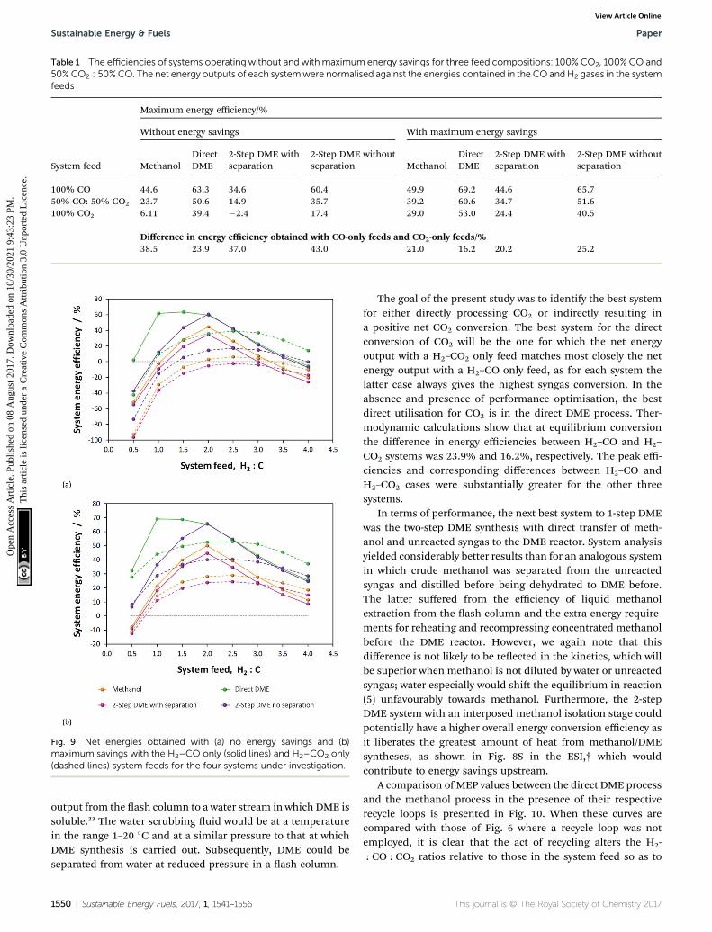
Table 1 The efficiencies of systems operating without and with maximum energy savings for three feed compositions: 100% CO2, 100% CO and50%CO2 : 50%CO. The net energy outputs of each systemwere normalised against the energies contained in the CO and H2 gases in the systemfeeds
System feed
Maximum energy efficiency/%
Without energy savings With maximum energy savings
MethanolDirectDME
2-Step DME withseparation
2-Step DME withoutseparation Methanol
DirectDME
2-Step DME withseparation
2-Step DME withoutseparation
100% CO 44.6 63.3 34.6 60.4 49.9 69.2 44.6 65.750% CO: 50% CO2 23.7 50.6 14.9 35.7 39.2 60.6 34.7 51.6100% CO2 6.11 39.4 �2.4 17.4 29.0 53.0 24.4 40.5
Difference in energy efficiency obtained with CO-only feeds and CO2-only feeds/%38.5 23.9 37.0 43.0 21.0 16.2 20.2 25.2
Fig. 9 Net energies obtained with (a) no energy savings and (b)maximum savings with the H2–CO only (solid lines) and H2–CO2 only(dashed lines) system feeds for the four systems under investigation.
Sustainable Energy & Fuels Paper
Ope
n A
cces
s A
rtic
le. P
ublis
hed
on 0
8 A
ugus
t 201
7. D
ownl
oade
d on
10/
30/2
021
9:43
:23
PM.
Thi
s ar
ticle
is li
cens
ed u
nder
a C
reat
ive
Com
mon
s A
ttrib
utio
n 3.
0 U
npor
ted
Lic
ence
.View Article Online
output from the ash column to a water stream in which DME issoluble.23 The water scrubbing uid would be at a temperaturein the range 1–20 �C and at a similar pressure to that at whichDME synthesis is carried out. Subsequently, DME could beseparated from water at reduced pressure in a ash column.
1550 | Sustainable Energy Fuels, 2017, 1, 1541–1556
The goal of the present study was to identify the best systemfor either directly processing CO2 or indirectly resulting ina positive net CO2 conversion. The best system for the directconversion of CO2 will be the one for which the net energyoutput with a H2–CO2 only feed matches most closely the netenergy output with a H2–CO only feed, as for each system thelatter case always gives the highest syngas conversion. In theabsence and presence of performance optimisation, the bestdirect utilisation for CO2 is in the direct DME process. Ther-modynamic calculations show that at equilibrium conversionthe difference in energy efficiencies between H2–CO and H2–
CO2 systems was 23.9% and 16.2%, respectively. The peak effi-ciencies and corresponding differences between H2–CO andH2–CO2 cases were substantially greater for the other threesystems.
In terms of performance, the next best system to 1-step DMEwas the two-step DME synthesis with direct transfer of meth-anol and unreacted syngas to the DME reactor. System analysisyielded considerably better results than for an analogous systemin which crude methanol was separated from the unreactedsyngas and distilled before being dehydrated to DME before.The latter suffered from the efficiency of liquid methanolextraction from the ash column and the extra energy require-ments for reheating and recompressing concentrated methanolbefore the DME reactor. However, we again note that thisdifference is not likely to be reected in the kinetics, which willbe superior when methanol is not diluted by water or unreactedsyngas; water especially would shi the equilibrium in reaction(5) unfavourably towards methanol. Furthermore, the 2-stepDME system with an interposed methanol isolation stage couldpotentially have a higher overall energy conversion efficiency asit liberates the greatest amount of heat from methanol/DMEsyntheses, as shown in Fig. 8S in the ESI,† which wouldcontribute to energy savings upstream.
A comparison of MEP values between the direct DME processand the methanol process in the presence of their respectiverecycle loops is presented in Fig. 10. When these curves arecompared with those of Fig. 6 where a recycle loop was notemployed, it is clear that the act of recycling alters the H2-: CO : CO2 ratios relative to those in the system feed so as to
This journal is © The Royal Society of Chemistry 2017

Fig. 10 MEP increase of the direct DME process relative to methanolalone; calculations based on system outputs (post flash separation anddistillation processes etc.).
Paper Sustainable Energy & Fuels
Ope
n A
cces
s A
rtic
le. P
ublis
hed
on 0
8 A
ugus
t 201
7. D
ownl
oade
d on
10/
30/2
021
9:43
:23
PM.
Thi
s ar
ticle
is li
cens
ed u
nder
a C
reat
ive
Com
mon
s A
ttrib
utio
n 3.
0 U
npor
ted
Lic
ence
.View Article Online
inhibit system performance for the direct DME case. This is dueto the formation and build-up of CO2 via the water gas shireaction between CO and the H2O that is formed duringmethanol dehydration. It is for this reason that such relativelyhigh performance with H2–CO2 only feeds can be achieved. Thelarge build-up of CO2 with a H2–CO feed in the direct DMEprocess relative to the other systems is conrmed in Fig. 11,where the CO : CO2 ratio in the recycle loop is in the range 0.6–25, despite the ratio being 260 000 in the system feed (we notethat for a ‘H2 : CO-only’ system, a small molar fraction of CO2
was fed into the system together with CO in order to preventexcessive CO2 build-up). The differences in the ratios for theother systems are due to variances in the separation efficienciesof CO2 as gas in the ash column.
Fig. 11 CO : CO2 ratios in the recycle loops for the methanol/DMEsynthesis systems, fed only with H2 and CO.
This journal is © The Royal Society of Chemistry 2017
In principle, all or part of the CO2 in the recycle loop can beremoved simultaneously with DME using a scrubbing solvent,such as a mixture of methanol and DME.28 However, subse-quently several stages to separate the DME from the CO2 andalso to recycle the scrubbing solvent will be required. The CO2
will also need to be recycled upstream of the reactor in order notto be emitted to the atmosphere. Alternatively, the CO2 andDME could be condensed out of the gaseous mixture.29
However, the combined CO2/DME removal and separationprocess will certainly result in a substantial efficiency penalty.
CO2 emissions were computed for the methanol/DMEsynthesis systems and included contributions from: CO2
emitted directly in the vented gases, additional CO2 emitted inthe vented gases as a result of complete CO combustion in theenergy saving scheme, CO2 contained in the crude methanolstreams from the ash columns and CO2 emitted to power theprocess components, where the energy requirements were notmet by the combustion of vented CO and H2. Results are shownin Fig. 12 and demonstrate that, unlike in the single passscenario, CO2 emissions are minimal in the direct DMEsynthesis system.
Fig. 12 shows that the presence of a recycle loop minimisedthe emissions of CO2, which would otherwise have been verysignicant in the direct DME synthesis system operating withCO. In fact, CO2 emissions were greater for all systems utilisingH2–CO2 only feeds due to the lower product yields (relative toH2–CO feeds) and the greater amounts of energy required to runthe systems and maintain large amounts of unreacted gases inthe recycle loops.
In summary, according to thermodynamic equilibriumcalculations and system analysis, when CO2 is utilised as theprincipal source of carbon, the highest net energy outputs wereachieved with the direct DME synthesis system. This systemalso demonstrated the highest overall performance with CO,albeit the MEP is reduced signicantly by the large build-up of
Fig. 12 CO2 emissions normalised by the MEP for the methanol/DMEproduction systems employing H2–CO only (solid lines) and H2–CO2
only (dashed lines) feeds.
Sustainable Energy Fuels, 2017, 1, 1541–1556 | 1551

Sustainable Energy & Fuels Paper
Ope
n A
cces
s A
rtic
le. P
ublis
hed
on 0
8 A
ugus
t 201
7. D
ownl
oade
d on
10/
30/2
021
9:43
:23
PM.
Thi
s ar
ticle
is li
cens
ed u
nder
a C
reat
ive
Com
mon
s A
ttrib
utio
n 3.
0 U
npor
ted
Lic
ence
.View Article Online
CO2 in the recycle loop due the water gas shi reaction betweenCO and the water generated by in situ methanol dehydration.Performance with CO2 as the carbon source can theoretically belower than the performance with CO by only 16.2%, providedenergy saving strategies such as coupling of heat exchangersand the combustion of vented CO and H2 to generate thermaland electrical energies are employed. Hence, direct utilisationof CO2 is preferable in the direct DME system rather than insystems producing only methanol in the rst stage. This systemalso achieves the highest degree of CO2 conversion.
Conversion of CO2 to CO upstream of the DME system thatappears necessary for systems where methanol is produced inthe rst stage, would not be benecial if the increase in the netenergy yields are balanced or even outweighed by the energyrequirements of this additional step. Upstream syngas produc-tion needs to be analysed with two points in mind. Firstly, basedon the ndings in this study, direct utilisation of CO2 requires atleast 1.25 timesmore hydrogen in the system feed than when COis used and this would result in additional penalties both interms of energy requirement and CO2 emissions. Secondly, theheat liberated by reactions (1)–(3) and (5) in the methanol/DMEreactors, and extracted in order to maintain isothermal condi-tions can be recovered and used to support upstream processesfor generating H2 and CO from H2O and CO2. Fig. 8S in the ESI†shows the heats liberated in the methanol and DME synthesisreactors under consideration in this study. More heat is liberatedby CO dehydration than by CO2 dehydration. Hence, again, thebenets of a H2–CO only syngas could potentially be reversed ifthe upstream processes for converting CO2 and H2O to CO andH2 require substantially greater energy inputs than energyrecoverable from the downstream reaction heat.
Hence, the criterion for directing the decision of whether touse CO2 or CO (produced upstream from CO2) as the principalsources of carbon in the feed for methanol/DME syntheses isthat the value of ‘net energy gain from using CO instead of CO2
in methanol/DME syntheses’ is greater than the ‘energyrequired to generate syngas of the required composition’, withaccount taken for heat recoverable from downstreamexothermic processes. An additional criterion is that the CO2
liberated to support the running of the systems must be onlya small fraction of the CO2 utilised. Naturally, the decisionwould also be dictated by availability of catalysts able to supportdirect CO2 conversion to methanol, although as evidenced fromref. 11–13 this can already be carried out at industrial scale.
Syngas production from CO2 and H2O
With decontaminated H2O and CO2 as the building blocks,syngas may be produced electrochemically and/or via the WGS/RWGS reactions (3) using a variety of means depicted in Fig. 13.Hydrogen may be generated by the reduction of water in anelectrolyser via reaction (11). The most commonly used deviceon an industrial scale is an alkaline electrolyser, which is typi-cally operated at elevated temperatures in the range 60–90 �Cand can also be performed at pressures up to 700 bar. Usuallythese devices operate with an energy efficiency of up to 70% anda faradaic efficiency close to unity.
1552 | Sustainable Energy Fuels, 2017, 1, 1541–1556
2H2O + 2e�% H2 + 2OH� (11)
A typical specic electrical energy consumption for alkalinewater electrolysis at atmospheric pressure and at 75 �C withoutaccount of parasitic energy losses or gas losses is ca. 4.5 kW hNm(H2)
�3 z 100 kW h kmol(H2)�1.35
Hydrogen produced by electrolysis may be utilised directly asshown in schemes (a)–(c) and (e) in Fig. 13 and/or reacted withCO2 via the RWGS process shown in (b) to generate a mixture ofCO, H2O, CO2 and H2, from which CO and H2 can then beisolated and fed into the methanol/DME reactors. Schemes (a),in which a CO2-based syngas is generated, and (b), in whicha CO-based syngas is generated, are based on readily availabletechnologies with well-characterised performance.
In an alternative scheme to (b), CO may be produceddirectly by CO2 reduction using a technology that is stillcurrently in the research phase: solid oxide electrolysis.36
During the reduction reaction (12), CO2 is split into CO andoxide ions; the oxide ions migrate across a solid oxide elec-trolyte and become oxidised to oxygen gas. The net systemreaction is shown in eqn (13). This process takes place atelevated temperatures (typically 500–800 �C), which arerequired to achieve a sufficient conductivity in the solid oxideelectrolyte. CO produced in this way may be reacted directlywith H2 to form methanol/DME etc., as shown in scheme (c) orreacted with water vapour via the WGS process to generatea mixture of H2, CO2, H2O and CO, as shown in scheme (f).Although this technology is still very much under develop-ment, CO2 electrolysis in solid oxide systems is already beingcarried out industrially, for example by Haldor Topose.37
CO2 + 2e�% CO + O2� (12)
2CO2 % 2CO + O2 (13)
The specic electrical energy consumption for the produc-tion of CO via high temperature electrolysis of CO2 is reportedto be of order 2.1 kW h kg(CO2)
�1 (ref. 36) at 800 �C and 1 atm.,corresponding to z92 kW h kmol(CO)�1.
High temperature CO2 electrolysis is reported to be moreefficient if it is carried out simultaneously with the reduction ofsteam as per reaction (14), in a process termed co-electrolysis.38
This process has two principal advantages over the scheme in(13) rstly because CO2 reduction is aided by the RWGS processthat takes place as H2 is formed and secondly because itsuppresses the formation of solid carbon.
CO2 þ nH2O%COþ nH2 þ ð1þ nÞ2
O2 (14)
The H2 : CO ratio in the resultant syngas is controlled by theH2O : CO2 ratio in the feed.39 For example, the specic electricalenergy consumption for co-electrolysis at 800 �C and 1 atm.generating syngas with a molar ratio of H2 : CO ¼ 2.0 is esti-mated at 3.2 kW h Nmsyngas
�3. Co-electrolysis can be used asa standalone process to generate a H2–CO syngas as shown in
This journal is © The Royal Society of Chemistry 2017

Fig. 13 Possible routes for the production of syngas, with varying ratios of H2 : C, from H2O and CO2.
Paper Sustainable Energy & Fuels
Ope
n A
cces
s A
rtic
le. P
ublis
hed
on 0
8 A
ugus
t 201
7. D
ownl
oade
d on
10/
30/2
021
9:43
:23
PM.
Thi
s ar
ticle
is li
cens
ed u
nder
a C
reat
ive
Com
mon
s A
ttrib
utio
n 3.
0 U
npor
ted
Lic
ence
.View Article Online
scheme (d), or performed in parallel with CO2 electrolysis as inscheme (e) if the H2–CO ratio requires adjustment.
The energy requirements of schemes (a)–(f) in Fig. 13 wereevaluated based on the specic electrical energy consumptionsfor alkaline electrolysis (75 �C, 1 atm.), CO2 electrolysis (800 �C,1 atm.) and CO2–H2O co-electrolysis (800 �C, 1 atm.) specied inref. 35, 36 and 39, respectively, and simulations of the RWGS/WGSprocesses, as well as energy demands of heat exchangers andcompressors relevant to each scheme, in Aspen Plus V8.8.
Stage 1 energy consumptions were used to determine thedifferences between normalised energies required to produceCO2-based syngas (scheme in Fig. 13a) with the optimumH2 : CO2 ratio of 2.5 for both methanol and DME syntheses andCO-based syngas with H2 : CO ratios of 2 and 1 for methanoland direct DME processes, respectively (schemes (b)–(f)). Thesedifferences are shown in Fig. 14, where they are compared withthe normalised energy gains in Stage 2 that were achieved whena CO-based rather than CO2-based syngas was used in theproduction of methanol (Fig. 14a) and DME by the directprocess (Fig. 14b). Results show that in the case of methanolsynthesis, the benets of a CO-based feed in Stage 2 alwaysoutweigh any additional energy requirements in Stage 1,regardless of which syngas production scheme was employed.Furthermore, when schemes (c) and (e) were used to produceCO-based syngas, less energy was consumed than in theproduction of hydrogen in scheme (a). Scheme (e) appears to bethe best for producing syngas with the correct ratios for bothmethanol and DME synthesis, although it should be noted thatthe specic electrical energy consumption used in assessmentof schemes (d) and (e)39 was not determined experimentally,
This journal is © The Royal Society of Chemistry 2017
unlike in the other schemes. Hence, further validation may benecessary. In the case of DME production, scheme (b) generatedthe worst case scenario, which showed that losses in Stage 1were greater than gains in Stage 2.
As well as energy consumption, the combined CO2
utilisation/emissions associated with Stages 1 and 2 are ofcritical importance in identifying the best system for CO2
conversion to fuels. The CO2 consumed (by conversion to CO)and liberated (to support process energy demands) wascomputed for each Stage 1 scheme in Fig. 13; the net differenceswere normalised against the energies contained in the nalsyngas products, as shown in eqn (15). This enabled thecomparison of net CO2 consumption in Stage 1 (negative forschemes (b)–(f) and positive for scheme (a)) with CO2 emissionsin Stage 2, evaluated using eqn (16).
Stage 1: CO2ðemittedÞ ¼ CO2ðemittedÞ � CO2ðconsumedÞ�Esyngas
�out
(15)
Stage 2 : CO2ðutilisedÞ ¼ CO2ðventedÞ � CO2ðinÞ�Esyngas
�in
(16)
When CO2 was converted to CO upstream of the methanol/DME reactors (schemes (b)–(f) in Fig. 13), net CO2 utilisationwas achieved in Stage 1, whereas direct use of CO2 in themethanol/DME reactors (scheme (a)) resulted in net CO2 uti-lisation in Stage 2. Fig. 15 shows a comparison of the relativeCO2 utilisation and emissions, both normalised by the energycontained in the syngas, in Stages 1 and 2 of systems producingmethanol and DME via the direct process. The direct DME
Sustainable Energy Fuels, 2017, 1, 1541–1556 | 1553

Fig. 14 Relative normalised energy losses in Stage 1 and gains in Stage2 when (a) methanol and (b) direct DME systems are operated withCO-based and CO2-based syngas.
Fig. 15 Relative CO2 emissions and CO2 utilisation occurring in Stages1 and 2 of systems for the production of methanol and direct DME.Negative CO2 emissions (green) represent net CO2 utilisation occur-ring in Stage 1 for schemes (b)–(f) in Fig. 13 and in Stage 2 for scheme(a). Conversely, positive CO2 emissions (red) represent CO2 liberated inStage 2 for schemes (b)–(f) (due to WGS reaction) and in Stage 1 forscheme (a). Percentage values indicate the proportion of consumedCO2 that is re-emitted. Direct CO2 utilisation is modelled in the directDME process, requiring syngas with H2 : CO2 ¼ 2.5 produced inscheme (a). The remaining schemes convert CO2 to CO in Stage 1,generating syngas with H2 : CO ¼ 2 for methanol production andH2 : CO ¼ 1 for DME production via the direct process in Stage 2.
Sustainable Energy & Fuels Paper
Ope
n A
cces
s A
rtic
le. P
ublis
hed
on 0
8 A
ugus
t 201
7. D
ownl
oade
d on
10/
30/2
021
9:43
:23
PM.
Thi
s ar
ticle
is li
cens
ed u
nder
a C
reat
ive
Com
mon
s A
ttrib
utio
n 3.
0 U
npor
ted
Lic
ence
.View Article Online
process was modelled to utilise CO2-based syngas directly(produced in scheme (a) in Fig. 13) with the optimum H2 : CO2
ratio of 2.5 identied earlier and also CO-based syngas producedin schemes (b), (c), (e) and (f) with H2 : CO ¼ 1. Due to the poorperformance of the methanol and 2-step DME systems with CO2
in the feed, the methanol system was modelled with a CO-basedsyngas only, using schemes (b), (c), (d) and (f) with H2 : CO ¼ 2.
The results presented in Fig. 15 show that while theproduction of syngas with H2 : CO ratio of 1 in Stage 1, tailoredfor direct DME synthesis, leads to the highest CO2 utilisation,the benets are offset substantially by the generation of CO2 bythe water gas shi reaction in Stage 2. For all the schemesconsidered, it has been calculated that between 50–54% of CO2
consumed in Stage 1 is regenerated in Stage 2. The extent of CO2
regeneration is reduced to 48% if direct DME synthesis is per-formed with CO2 rather than CO, thereby conrming that directutilisation of CO2 is possible and thermodynamically preferablewith this process.
Results in Fig. 15 show unambiguously that if CO2 is con-verted to CO in Stage 1, then it is substantially better to use thisCO for the production of methanol (or DME via the two-steproutes) rather than DME via the direct route.
1554 | Sustainable Energy Fuels, 2017, 1, 1541–1556
The conversion of CO2 to CO via high temperature electrolysis,followed by the WGS reaction with H2O (scheme (f) with H2 : CO¼ 2 in the nal syngas product) resulted in the highest degree ofCO2 utilisation, with only 9% regenerated in Stage 2. The betterperformance of the system in scheme (f) is principally due to theexothermic nature of the WGS reaction which reduces the energyrequirements in Stage 1. There was no signicant differencebetween the performances of methanol systems with schemes(b), (c) or (d) in Stage 1. We note that additional energy require-ments associated with cooling the WGS reactor have not beenconsidered; these and other subordinate elements were beyondthe scope of the present estimations. Nonetheless, Fig. 9S in theESI† shows the energies released as heat (by exothermic reactionsin Stage 2 processes such asWGS and by heat exchangers in Stage1) relative to energy demands in Stage 1 for each scenario pre-sented in Fig. 15; a fraction of the energy released as heat couldbe harnessed and used to decrease the energy consumption inStage 1. However, conclusions based on the results in Fig. 15 areunlikely to be altered by these potential savings.
Based on results in Fig. 14 and 15 it can be concluded that interms of energetic benets and CO2 utilisation, methanol is bestsynthesised from CO-based syngas that is produced upstreamusing high temperature electrolysers or a combination of hightemperature CO2 electrolysis coupled with a WGS system. Onthe other hand, the direct DME process can utilise CO2 directly;alternatively it can utilise syngas produced using the samemethods as those identied for the case of methanol. In thecases of both methanol and direct DME syntheses, syngasproduction by a combination of an alkaline water electrolyserand a RWGS system yielded least favourable results.
This journal is © The Royal Society of Chemistry 2017
Paper Sustainable Energy & Fuels
Ope
n A
cces
s A
rtic
le. P
ublis
hed
on 0
8 A
ugus
t 201
7. D
ownl
oade
d on
10/
30/2
021
9:43
:23
PM.
Thi
s ar
ticle
is li
cens
ed u
nder
a C
reat
ive
Com
mon
s A
ttrib
utio
n 3.
0 U
npor
ted
Lic
ence
.View Article Online
In all cases, greater exibility with the design of Stage 1systems will be afforded when renewable sources of energy areavailable. For example, in the case of CRI,12,40 geothermal energysources provide steam, which is used for generating electricalenergy and for heating purposes. Alternatively solar energycould be used to generate electricity via photovoltaic devices,subject to location.
Although the supply of carbon dioxide is oen seen asunlimited due to the vast quantities in which it is generated byindustrial processes, its capture and purication are associatedwith signicant energy demands and hence already at thisinitial stage, a fraction of the CO2 recovered is released into theatmosphere;41 this factor will ultimately be important in lifecycle analyses on the methanol and DME synthesis systems thatutilise CO2 as the sole source of carbon. However, in this study,the source of CO2 and the energy associated with its recoveryand purication were not considered as it was not a factoraffecting system comparisons; CO2 of similar purity is required,regardless of whether it is rst converted to CO or fed intomethanol/DME reactors directly. For example, to avoid prob-lems associated with sulphur poisoning, the sulphur content inthe syngas for the commonly employed Cu-based methanol/DME catalysts needs to be below circa 1 ppm (ref. 7) and, like-wise, below circa 5 ppm for the nickel/iron/cobalt catalysts usedtypically in solid oxide electrolysers.42
Conclusions
The key question in this study was whether CO2 could be feddirectly to methanol/DME synthesis systems or whether itsupstream conversion to CO was necessary. Hence, system effi-ciencies and extents of CO2 conversion were examined in fourmethanol/DME synthesis systems as a function of hydrogen tototal carbon molar ratios, H2 : (CO2 + CO), as well as CO2 : COratios, in the system feed. Recycle of unreacted CO2, as well asH2 and CO, was enabled to minimise CO2 emissions. Energyrequirements for the operation of heat exchangers, compressorsand distillation columns, as well as energy saving strategiessuch as the coupling of heat exchangers and also the utilisationof energy generated by combustion of vented gases, wereincluded in system assessment. Highest system efficiencies forthe methanol, direct DME and two-step DME synthesis systemswere obtained at a non-stoichiometric H2 : CO2 ratio of 2.5 inthe system feeds in the absence of upstream CO generation. ForCO-based syngas, the highest efficiencies for the methanol/two-step DME and direct DME synthesis systems were obtained atstoichiometric H2 : CO feed ratios of 2 and 1, respectively.Direct utilisation of CO2 required maximum energy savings.
Taking account of energy requirements and CO2 emissionsassociated with the upstream syngas production stage, it wasdetermined that CO2 could be utilised directly in the directDME synthesis route, whereas upstream conversion of CO2 toCO was necessary to achieve signicant yields and increasedoverall CO2 conversion with the methanol/two-step DMEsystems.
CO-based syngas production via high temperature co-electrolysis of H2O and CO2, or alternatively high temperature
This journal is © The Royal Society of Chemistry 2017
CO2 electrolysis coupled with the WGS process, were identiedas the best technologies based on energy consumption and CO2
conversion.
Acknowledgements
The authors thank the UK Engineering and Physical SciencesResearch Council (EPSRC) for the post-doctoral research asso-ciateship for AH (grant EP/K035274/1). As per EPSRC require-ments, we have made our experimental data available viaZenodo.org. The link to the data is: https://zenodo.org/record/817412#.WUzky-vyvcs. It is also possible to access the data byentering the manuscript title into the search bar in http://www.zenodo.org.
References
1 A. Goeppert, M. Czaun, J. P. Jones, G. K. S. Prakash andG. A. Olah, Chem. Soc. Rev., 2014, 43, 7995.
2 IPCC, IPCC Guidelines for National Greenhouse GasInventories, Prepared by the National Greenhouse GasInventories Programme, ed. H. S. Eggleston, L. Buendia, K.Miwa, T. Ngara and K. Tanabe, IGES, Japan, 2006.
3 EU, Roadmap for moving to a low-carbon economy in 2050,European Commission, Brussels, Belgium, 2011, Shortversion, http://eur-lex.europa.eu/legal-content/EN/ALL/?uri¼CELEX:52011DC0112, accessed in 03/2017.
4 EU, Roadmap 2050: a practical guide to a prosperous, low-carbon Europe – Technical & economic analysis (full report),European Climate Foundation, 2010, http://www.roadmap2050.eu/reports, accessed in 03/2017.
5 G. A. Olah, A. Goeppert and G. K. S. Prakash, Beyond Oil andGas: The Methanol Economy, Wiley-VCH, Weinheim,Germany, 2nd edn, 2009.
6 G. A. Olah, A. Goeppert and G. K. S. Prakash, J. Org. Chem.,2009, 74, 487.
7 P. L. Spath and D. C. Dayton, Preliminary screening – technicaland economic assessment of synthesis gas to fuels and chemicalswith emphasis on the potential for biomass-derived syngas,NREL/TP-510–34929, 2003.
8 A. de Klerk and E. Furimsky, Catalysis in the Rening ofFischer-Tropsch Syncrude, Chapter 2: Production of SynthesisGas, Royal Society of Chemistry, 2010.
9 E. F. Sousa-Aguiar and L. Gorenstin Appel, Catalysis, 2011,23, 284.
10 Y. Ohno, et al., NKK Technical Review no. 85, 2001, pp. 23–28;Y. Ohno, Kagaku Keizai, 2004, 89–93.
11 T. Matsushita, T. Haganuma and D. Fujita, US Pat., 2013/0237618 A1, 2013.
12 http://carbonrecycling.is/, accessed in Dec 2016.13 A. M. Shulenberger, F. R. Jonsson, O. Ingolfsson and
K.-C. Tran, US Pat., 2007/0244208 A1, 2007.14 Blue Fuel Energy, http://bluefuelenergy.com/, accessed in
01/2017.15 G. Jacobs and B. H. Davis, Catalysis, 2007, 20, 122.16 G. C. Chinchen, P. J. Denny, D. G. Parker, M. S. Spencer,
K. C. Waugh and D. A. Whan, Appl. Catal., 1987, 30, 333–338.
Sustainable Energy Fuels, 2017, 1, 1541–1556 | 1555

Sustainable Energy & Fuels Paper
Ope
n A
cces
s A
rtic
le. P
ublis
hed
on 0
8 A
ugus
t 201
7. D
ownl
oade
d on
10/
30/2
021
9:43
:23
PM.
Thi
s ar
ticle
is li
cens
ed u
nder
a C
reat
ive
Com
mon
s A
ttrib
utio
n 3.
0 U
npor
ted
Lic
ence
.View Article Online
17 C. Kuechen and U. Hoffmann, Chem. Eng. Sci., 1993, 48,3767.
18 K. Klier, V. Chatikavanij, R. G. Herman and G. W. Simmons,J. Catal., 1982, 74, 343.
19 K. Law, J. Rosenfeld andM. Jackson,Methanol as a renewableenergy resource – White paper, TIAX LLC, 2013, http://www.methanolfuels.org/wp-content/uploads/2013/05/MI-Renewable-Methanol-Pathways-White-Paper_nal.pdf,accessed 03/2017.
20 L. Chen, Q. Jiang, Z. Song and D. Posarac, Chem. Eng.Technol., 2011, 34, 817.
21 Report: GHG emissions of Blue Fuel methanol productionprocess, (S&T)2 Consultants Inc, 2010, http://www.methanolfuels.org/about-methanol/environment/,accessed in 03/2017.
22 J. Haid and U. Koss, Lurgi's Mega-Methanol technologyopens the door for a new era in down-stream applications,Stud. Surf. Sci. Catal., 2001, 136, 399–404.
23 M. Cheiky and J. Hillier, US Pat., 8,835,517, 2014.24 J. Sun, G. Yang, Y. Yoneyama and N. Tsubaki, ACS Catal.,
2014, 4, 3346.25 X. D. Peng, B. A. Toseland and P. J. A. Tijm, Chem. Eng. Sci.,
1999, 54, 2787.26 Y. Ohno, M. Yoshida, T. Shikada, O. Inokoshi, T. Ogawa and
N. Inoue, JFE Technical Report No. 8, 2006.27 X. D. Peng, A. W. Wang, B. A. Toseland and P. J. A. Tijm, Ind.
Eng. Chem. Res., 1999, 38, 4381.28 X. D. Peng, B. W. Diamond, T. C. R. Tsao and B. L. Bhatt, US
Pat., 6,458,856, 2002.
1556 | Sustainable Energy Fuels, 2017, 1, 1541–1556
29 T. Shikada, Y. Ohno, T. Ogawa, M. Mizuguchi, M. Ono andK. Fujimoto, US Pat., 6,147,125, 2000.
30 J. M. Douglas, Conceptual design of chemical processes,McGraw-Hill, London, 1988.
31 T. Ogawa, N. Inoue, T. Shikada and Y. Ohno, J. Nat. GasChem., 2003, 12, 219.
32 W. M. Haynes, CRC Handbook of Chemistry and Physics, CRCpress, Taylor & Francis Group, London, 93rd edn, 2012.
33 2011 Guidelines to Defra/DECC’s GHG Conversion Factorsfor Company Reporting: Methodology Paper for EmissionFactors, August 2011, http://www.defra.gov.uk.
34 P. Patnaik, A Comprehensive Guide to the Hazardous Propertiesof Chemical Substances, Chapter 19: Gases, Common Toxic,and Flammable, John Wiley & Sons, Inc., 2007, pp. 402–409.
35 A. Roy, S. Watson and D. Ineld, Int. J. Hyd. Eng., 2006, 31,1964.
36 L. Kleiminger, T. Li, K. Li and G. H. Kelsall, RSC Adv., 2014, 4,50003.
37 Haldor Topsoe, http://www.topsoe.com/, accessed in 09/2016.
38 L. Kleiminger, T. Li, K. Li and G. H. Kelsall, Electrochim. Acta,2015, 179, 565.
39 Q. Fu, C. Mabilat, M. Zahid, A. Brisse and L. Gautier, EnergyEnviron. Sci., 2010, 3, 1382.
40 G. A. Olah and G. K. S. Prakash, US Pat., 8,791,166, 2014.41 N. von der Assen, J. Jung and A. Bardow, Energy Environ. Sci.,
2013, 6, 2721.42 J. Bøgild Hansen, Faraday Discuss., 2015, 182, 9.
This journal is © The Royal Society of Chemistry 2017