Embed Size (px)
Citation preview

SITCH CDRSurveying Investigative Transportable Cartographical Helper?
Sitchest Ish That Chu Heard?
“…we’re going to retrofit it.”

Receiving
ProcessingSensory Transmitting
MotorsData
Storage
Transmit Receive
Receive Transmit
Transmit Receive
ROBOT
BOOSTER
USER
High-level Functional Diagram
High Level Control: Commanding and Processing Movement and Environment

CPUsoftware Distance/ angle Image processing
Mapping Database
High-Level Software Design

ARM Cortex M-3
Object
Camera and Laser
Spy Camera
BRAIN
Magnetometer
UltrasonicSensors
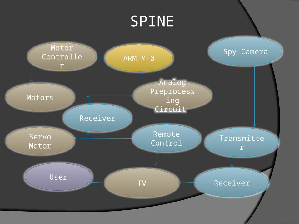
SPINE
ARM M-0Motor
Controller
User
Motors
Remote Control
Analog Preprocessing
Circuit
Servo Motor Transmitter
ReceiverTV
Receiver
Spy Camera

Ultrasonic Range Finder
Finds objects that may have been missed by the laser.
Allows basic object avoidance while the rover is in motion.
Model: LV-MaxSonar-EZ0
Status: Basic testing with Arduino-uno completed – developing interface for M0

Cortex M-3 Handles image processing and location
awareness. Sends position data to lower level motor
control loops.
Status: Developing camera interface.

CMOS Camera
CMOS Schematic EAGLE


Laser Range Finder Theory
Remember me?
This worked.

This Was Put Together

Calibration Data

Quite Grainy, Similar to how the CMOS camera will see imagesCMOS won’t have as many random colors
Took Pictures

Applied a Sharpening Function
Quite grainy
But the spot is brighter
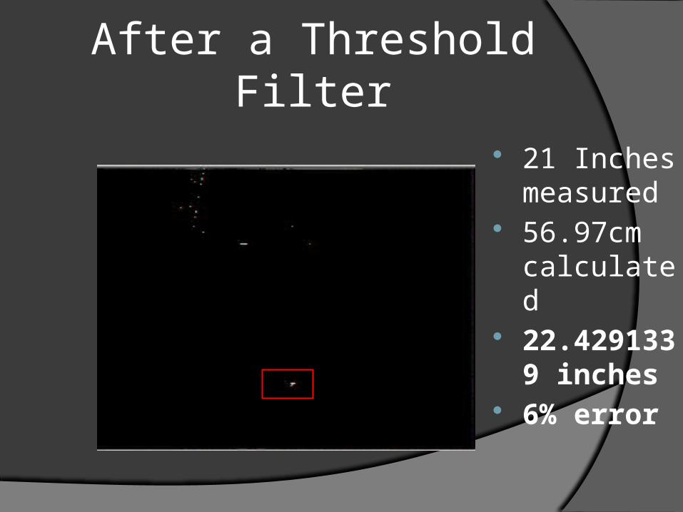
After a Threshold Filter
21 Inches measured
56.97cm calculated
22.4291339 inches
6% error

A Few Examples
91.44 cm

After 90.387 cm Calculated -1.15% error

Tried to Expand to Line Laser
Not very bright Used water Different laser
on its way

Room For Improvement
A line is visible Not mapped to angles Lost data
3 pts to 1 Great progress
High level goalwe have other options

Path Finding To be implemented after scanning and
image processing. Initially, perform rudimentary scan and
move aimlessly between obstacles. Ultimately, be able to negotiate past
objects to reach a waypoint. This waypoint may be provided with vector data
from stored encoder/magnetometer data.
Status: In development.

Low Level Control: Providing Fine Motor Control and Dead Reckoning
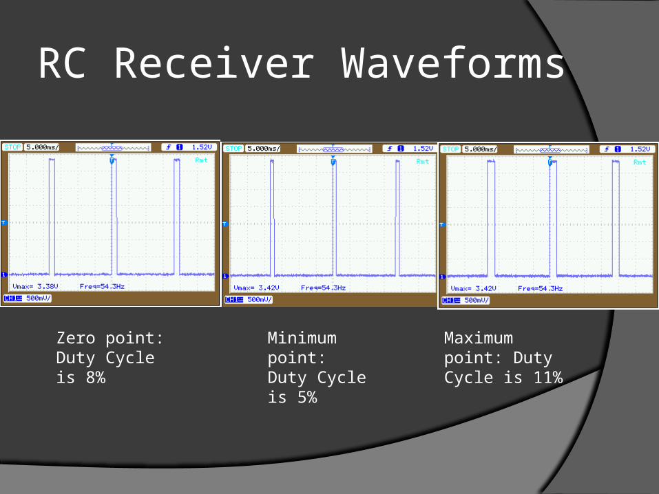
RC Receiver Waveforms
Zero point: Duty Cycle is 8%
Minimum point:Duty Cycle is 5%
Maximum point: Duty Cycle is 11%

Wireless Decoding
Receiver’s output must be digitized and encoded using the correct modulation
ADC will be used to measure the output of signal averager and output the corresponding modulation to the motor controllers

Schematic of the Signal Average Circuit

ARM Cortex M-0
Separate chip chosen to diversify processing abilities.
Simple motor control option. Designed to handle control loops. Hope to guarantee high responsiveness
of all sensors, computer and control systems.
Specific Model: LPC1114FHN33/302 Status: Initial development.

Distance Encoder
Basic device for measuring distance travelled.
Use paired IR LED/phototransistor and ADC to measure pinwheel rotation.
Status: Hardware complete.

Distance Encoder Schematic

Motor Controller
Current design based on 2 banks of 4 redundant L298N with opto-isolation.Each chip handles 4 amps with 2 parallel H-
bridges.32 amp total current handling.
If revised, it will be printed on PCB and based instead on H-bridge gate drivers and power MOSFETs.
Status: Fully functioning, but not ideal.

Motor Controller Schematic


Magnetometer Digital 3-axis magnetometer. Measures strength of magnetic field in
various directions with a highest field measurement resolution of 0.015 µT
Precise angular position determined through inverse tangent algorithm.
Communicates through I2C. Accurately determines location and
orientation. Status: Developing interface.

Magnetometer – Finer Details
Model No: LSM303DLH Breakout board from SparkFun

Power: Energizing Diverse Systems

Devices to Power on the Robot
Motor Controllers Radio Receivers and Video Transmitters Servo Motor (at least one) Processors Laser Cameras Magnetometer Ultrasonic Range Finder

Powering The Robot
Powered directly by a 7.4 V (2 cell) Lithium Polymer Battery
1st Choice - 6000mAh, 70C 2nd Choice - 12000mAh, 40C 3rd Choice – 2x 6000mAh, 30C

Powering Bot Movement
7.4V, XXX mAh, xxC2 cell LiPo
Driver Motor Controllers
Motors

5V Voltage Rail
Will be realized with a LM7805 voltage regulator chip.
Can supply up to 1.5 A of current
Status: Testing and laying out in Altium

3.3V Voltage Rail
Will be realized with a LM317 voltage regulator chip
Can supply up to 1.5 A of current
Status: Testing and laying out in Altium

3.3V Voltage Rail Schematic

MC34063A Chip – Boost Mode

Hi-Level Powering Diagram for Sensors
3.3V Voltage Rail
Step-up Voltage
Converter (12V)
Batteries
5 V Voltage Rail
CMOS Camera
Magnetometer
Video Transmitter
ARM M-0 Cortex M-3
Ultrasonic
RC Receiver
Laser

Power Consumption

Servo Motor Unable to find
datasheet Tested using
Arduino Uno, collected experimental data
Ready for integration with M0
Duty Cycle (%) Angular Position (degrees)
3.25 10
5.3 50
7.4 90
9.45 130
11.5 170
Servo PWM Signal InputVpp=~3.3V, f = 50Hz

Switching Microprocessors
C2000 Piccolo F28035 ARM Cortex-M0
Cryptic sample code Unhelpful documentation Steep Learning Curve
More intuitive Useful sample code Existing knowledge

Progress with ARM Cortex-M0
CurrentlySweeping PWMWorking ADC test function
GoalsWrite functions to increase user controlCommunicate with other modules

Video Camera Transmit video feed From Amazon, lacks
documentation Status: Transmitter
+ Receiver work – now we need to interface power supply and camera

PCB
Plan to lay out a board containing voltage rails and the boost converter
In the future include an ARM Cortex M0. Finalizing first draft of this PCB before
the end of this week

Planning: What the future holds

Design Goals Module Low Medium High
Power -Buy Chips-Etch PCB
-Buy Controllers-Design Converters
-Design all
Sensing -Stereoscopic -Single Laser and Camera
-Line laser
Image Processing
-Stereoscopic -Distance and angle from single laser -From line laser
Board Layout -Etch analog control circuit
-Print control circuit -2 processors 1 board
Motors -Elbow grease -Servo Motor moving sensor
-Moving 2 dimensions
µproccessing -RC Analog -ARM or FPGA -2 ARM processors
Booster -None -Increase operating range
-Multiple boosters
Collision Sensing
-None -Ultrasonic -None

Milestones and Expo
Milestone 1: RC control Motor drivers Magnetometer
Milestone 2:Laser range finding tower Ultrasonic
Expo: Path finding

Current Development
Finalize first revision of PCB Start constructing the mounts for the
laser range finder and motor drivers Integrate motor drivers with the M-0
control and batteries

Budget

QUESTIONS?