Embed Size (px)
Citation preview
CONNECTIONS FOR
TRANSPORTABLE AND STATIC BULK STORAGE TANKS
AIGA 024/10
Asia Industrial Gases Association
3 HarbourFront Place, #09-04 HarbourFront Tower 2, Singapore 099254
Tel : +65 6276 0160 • Fax : +65 6274 9379 Internet : http://www.asiaiga.org
© AIGA 2010 - AIGA grants permission to reproduce this publication provided the Association is acknowledged as the source
ASIA INDUSTRIAL GASES ASSOCIATION 3 HarbourFront Place, #09-04 HarbourFront Tower 2, Singapore 099254
Tel : +65 6276 0160 • Fax : +65 6274 9379 Internet : http://www.asiaiga.org
AIGA 024/10
CONNECTIONS FOR TRANSPORTABLE AND STATIC
BULK STORAGE TANKS
Disclaimer
All publications of AIGA or bearing AIGA’s name contain information, including Codes of Practice, safety procedures and other technical information that were obtained from sources believed by AIGA to be reliable and/ or based on technical information and experience currently available from members of AIGA and others at the date of the publication. As such, we do not make any representation or warranty nor accept any liability as to the accuracy, completeness or correctness of the information contained in these publications. While AIGA recommends that its members refer to or use its publications, such reference to or use thereof by its members or third parties is purely voluntary and not binding. AIGA or its members make no guarantee of the results and assume no liability or responsibility in connection with the reference to or use of information or suggestions contained in AIGA’s publications. AIGA has no control whatsoever as regards, performance or non performance, misinterpretation, proper or improper use of any information or suggestions contained in AIGA’s publications by any person or entity (including AIGA members) and AIGA expressly disclaims any liability in connection thereto. AIGA’s publications are subject to periodic review and users are cautioned to obtain the latest edition.
AIGA 024/10
Table of Contents
1 Introduction ........................................................................................................................................1
2 Scope .................................................................................................................................................1
3 Definitions .........................................................................................................................................1
4 Connections ......................................................................................................................................2 4.1 Guidelines for connection selection.............................................................................................2 4.2 Acceptable standard connections.............................................................................................2
4.2.1 Liquefied oxygen, nitrogen and argon...............................................................................2 4.2.2 Liquefied carbon dioxide and nitrous oxide .........................................................................3 4.2.3 Bulk compressed hydrogen and helium gas.........................................................................3
5 Safety precautions ..........................................................................................................................4 5.1 General.......................................................................................................................................4 5.2 Identification and labelling .........................................................................................................4 5.3 Control of the use of adaptors ..................................................................................................4
6 Supplier responsibility ......................................................................................................................4
7 Implementation................................................................................................................................5
8 References........................................................................................................................................5
Appendix A - CGA Connection No. AR-15 -Liquid argon ......................................................................6
Appendix B —CGA Connection No. AR-25 – Liquid argon ....................................................................7
Appendix C—CGA Connection No. NI-15 – Liquid nitrogen...................................................................8
Appendix D— CGA Connection No. NI-25 – Liquid nitrogen..................................................................9
Appendix E— CGA Connection No. OX-15 – Liquid oxygen ................................................................10
Appendix F— CGA Connection No. OX-30 – Liquid oxygen ................................................................11
Appendix G – CGA Connection No. Carbon dioxide 1-1/2"................................................................12
Appendix H – CGA Connection No. Carbon dioxide 3" .......................................................................13
Appendix I - CGA Connection No. 1350 – Bulk hydrogen ...................................................................14
Appendix J – CGA Connection No. 1340 – Bulk helium.......................................................................15
Appendix K (i) Index Plate - DN 40 LAR– Liquid argon ........................................................................16
Appendix K (ii) Index Plate - DN 40 LIN – Liquid nitrogen....................................................................16
Appendix K (iii) Index Plate - DN 40 LOX – Liquid oxygen...................................................................17
Appendix K (iv) Index Plate – Fixed end piece .....................................................................................17
Appendix K (v) Index Plate – Studs ......................................................................................................18
Appendix K(vi) Index Plate – Complete coupling views.......................................................................19
Appendix L - Ramped bayonet claw coupling – Liquid argon...............................................................20

AIGA 024/10
Appendix M – Ramped bayonet claw coupling – Liquid nitrogen .........................................................21
Appendix N – Ramped bayonet claw coupling – Liquid oxygen...........................................................22
Appendix O – CGA Connection No. N2O-10.........................................................................................23
Appendix P – CGA Connection No. N2O-15 .........................................................................................24
AIGA 024/10
1
1 Introduction In many Asian countries, there are no clear standards for product inlet/outlet connections for transportable and static storage vessels for bulk liquefied and compressed gases. The prevalence of large numbers of alternative connections within the industry and the consequent dependence on adaptors to connect between them is regarded as being potentially hazardous. Hence there is a high risk of the wrong product(s) being introduced to the consumer’s supply system. The hazards associated with connecting the wrong products to the consumer’s supply system include loss of production, property damage and injury to personnel. There is a need for standardization of the product connections for bulk liquefied and compressed gases to eliminate filling errors at source and the incorrect product delivery to the consumer’s supply systems. Adoption of these standards should mitigate the risks associated with filling transportable equipment and or static tanks with the incorrect product and also minimize the need for using adapters. 2 Scope This document is pertinent to connections associated with the filling and discharge of transportable and static storage vessels for bulk liquefied and compressed gases. It applies specifically to the following list of gases for industrial and medical applications Liquefied oxygen Liquefied nitrogen Liquefied argon Liquefied carbon dioxide Liquefied nitrous oxide Bulk gaseous hydrogen Bulk gaseous helium 3 Definitions
Adaptor : A device enabling two different yet acceptable CONNECTIONS for the SAME PRODUCT (See Table 1, 2 and 3) to be coupled for product transfer.
Connection : A recognized standard device and its mating device that discriminate between products defined in the scope of this document and typically mounted on the inlets/outlets of a transportable and static storage vessel(s) and or their transfer hoses.
Pressure : In this document, bar shall indicate gauge pressure unless otherwise
noted, i.e. (bar, abs) for absolute pressure and (bar, dif) for differential pressure.
Shall : The use of the word “shall” in this document implies a very strong concern or instruction.
Should : The use of the word “should” in this document indicates a recommendation.
Static storage vessel : Static storage vessels are designed to be mounted on foundation typically at production and consumer sites.
AIGA 024/10
2
Transportable storage vessel(s): Transportable storage vessel(s) are designed with a permanent chassis or designed to be transported on a chassis such as an ISO frame. Multiple vessels may be mounted on a single chassis.
Transfer hose : Transfer hoses may be considered as an extension to the transportable or static storage vessel connections. They may also be considered as adaptors provided they meet the intent as per the definition.
4 Connections
4.1 Guidelines for connection selection
• Connections must discriminate and thus be product specific and must not be in conflict. “In
conflict” meaning that the same connection is used for dissimilar products by different suppliers or in different geographic regions.
• Connections must be constructed of material compatible with the product service.
• Connections must be of reliable design and construction to eliminate failure during product
transfer. Connections should be designed so that they cannot be modified easily to accommodate the transferring of other product.
4.2 Acceptable standard connections
4.2.1 Liquefied oxygen, nitrogen and argon
Based on a survey of the connections in use in Asia and on the guidelines in this document, the following 3 categories of connections are classified as the ACCEPTABLE STANDARD CONNECTIONS for continued use.
• CGA – ACME threaded type
• Indexed plate type
• Ramped bayonet claw type
It is further recommended that the national gas associations adopt a single connection standard from those listed above giving priority to fill connections for transportable storage vessels.
AIGA 024/10
3
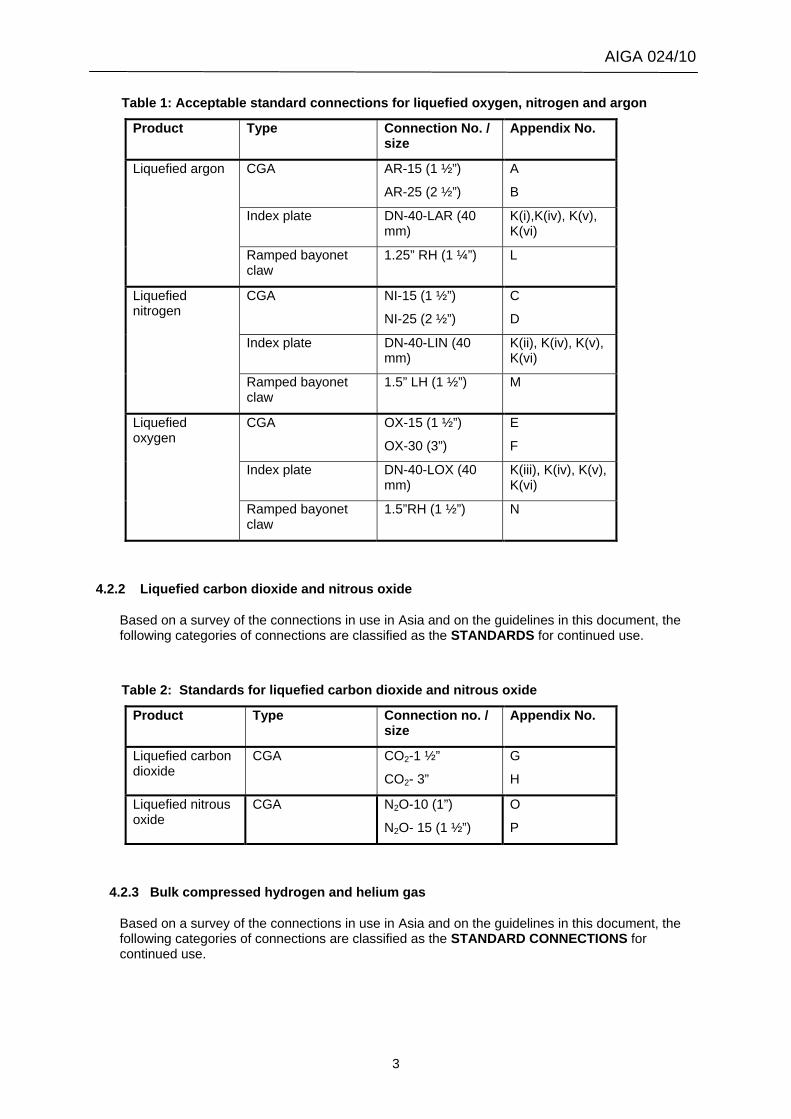
Table 1: Acceptable standard connections for liquefied oxygen, nitrogen and argon
Product Type Connection No. / size
Appendix No.
Liquefied argon CGA
AR-15 (1 ½”)
AR-25 (2 ½”)
A
B
Index plate DN-40-LAR (40 mm)
K(i),K(iv), K(v), K(vi)
Ramped bayonet claw
1.25” RH (1 ¼”) L
Liquefied nitrogen
CGA
NI-15 (1 ½”)
NI-25 (2 ½”)
C
D
Index plate DN-40-LIN (40 mm)
K(ii), K(iv), K(v), K(vi)
Ramped bayonet claw
1.5” LH (1 ½”) M
Liquefied oxygen
CGA OX-15 (1 ½”)
OX-30 (3”)
E
F
Index plate DN-40-LOX (40 mm)
K(iii), K(iv), K(v), K(vi)
Ramped bayonet claw
1.5”RH (1 ½”) N
4.2.2 Liquefied carbon dioxide and nitrous oxide
Based on a survey of the connections in use in Asia and on the guidelines in this document, the following categories of connections are classified as the STANDARDS for continued use.
Table 2: Standards for liquefied carbon dioxide and nitrous oxide Product Type Connection no. /
size Appendix No.
Liquefied carbon dioxide
CGA CO2-1 ½”
CO2- 3”
G
H
Liquefied nitrous oxide
CGA N2O-10 (1”)
N2O- 15 (1 ½”)
O
P
4.2.3 Bulk compressed hydrogen and helium gas
Based on a survey of the connections in use in Asia and on the guidelines in this document, the following categories of connections are classified as the STANDARD CONNECTIONS for continued use.
AIGA 024/10
4
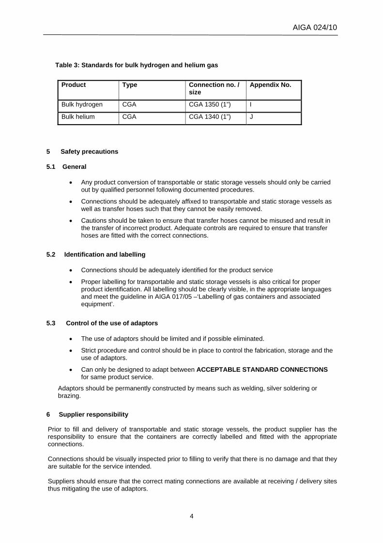
Table 3: Standards for bulk hydrogen and helium gas
Product Type Connection no. /
size Appendix No.
Bulk hydrogen CGA CGA 1350 (1”) I
Bulk helium CGA CGA 1340 (1”) J
5 Safety precautions
5.1 General
• Any product conversion of transportable or static storage vessels should only be carried out by qualified personnel following documented procedures.
• Connections should be adequately affixed to transportable and static storage vessels as well as transfer hoses such that they cannot be easily removed.
• Cautions should be taken to ensure that transfer hoses cannot be misused and result in the transfer of incorrect product. Adequate controls are required to ensure that transfer hoses are fitted with the correct connections.
5.2 Identification and labelling
• Connections should be adequately identified for the product service
• Proper labelling for transportable and static storage vessels is also critical for proper product identification. All labelling should be clearly visible, in the appropriate languages and meet the guideline in AIGA 017/05 –‘Labelling of gas containers and associated equipment’.
5.3 Control of the use of adaptors
• The use of adaptors should be limited and if possible eliminated.
• Strict procedure and control should be in place to control the fabrication, storage and the use of adaptors.
• Can only be designed to adapt between ACCEPTABLE STANDARD CONNECTIONS for same product service.
Adaptors should be permanently constructed by means such as welding, silver soldering or brazing.
6 Supplier responsibility Prior to fill and delivery of transportable and static storage vessels, the product supplier has the responsibility to ensure that the containers are correctly labelled and fitted with the appropriate connections.
Connections should be visually inspected prior to filling to verify that there is no damage and that they are suitable for the service intended. Suppliers should ensure that the correct mating connections are available at receiving / delivery sites thus mitigating the use of adaptors.
AIGA 024/10
5
Suppliers are responsible for developing and implementing appropriate procedures for the fabrication, storage and use of adaptors. Suppliers should provide adequate training for all personnel involved in transferring of bulk liquefied and compressed gases included but not limited to the requirement of this standard. 7 Implementation National gas associations and product suppliers should adopt this standard in its entirety with full compliance not later than December 2010. 8 References AIGA 017/05 Labelling of gas containers and associated equipment CGA: V-6 -2008 5th edition Standard bulk refrigerated liquid transfer connections CGA: V-10 -2010 4th edition High pressure gas trailer connections
AIGA 024/10
6
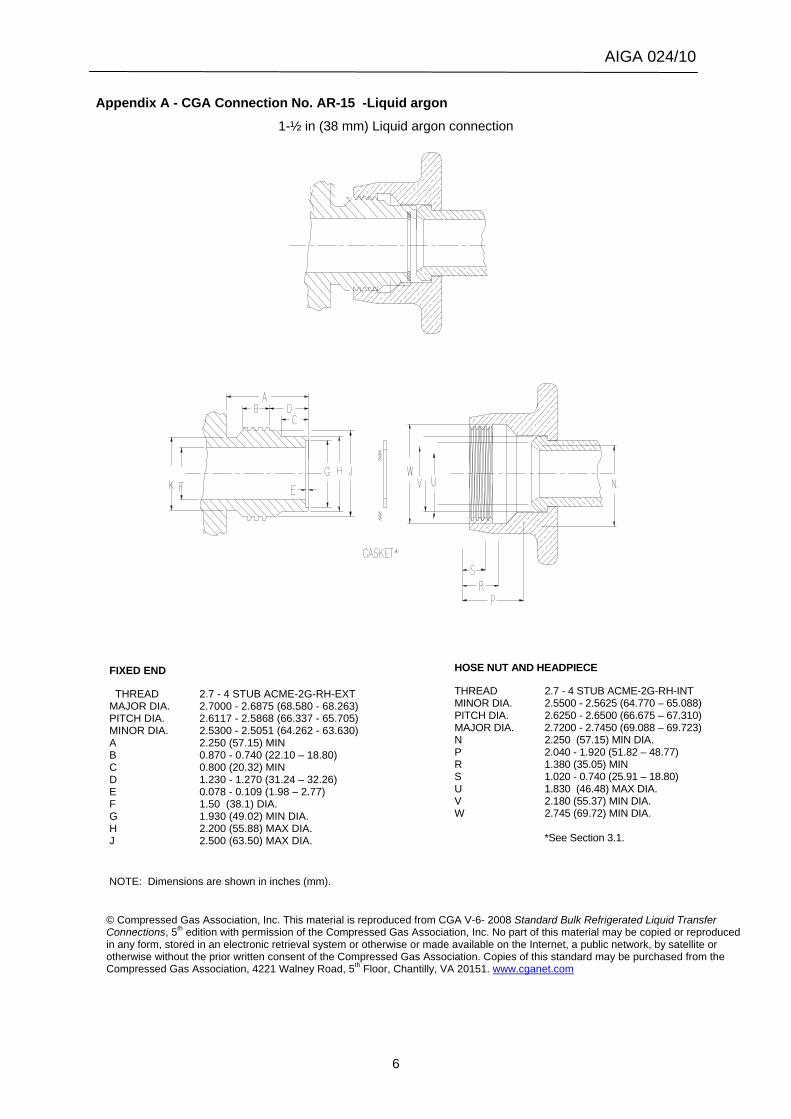
Appendix A - CGA Connection No. AR-15 -Liquid argon
1-½ in (38 mm) Liquid argon connection
FIXED END
THREAD 2.7 - 4 STUB ACME-2G-RH-EXT MAJOR DIA. 2.7000 - 2.6875 (68.580 - 68.263) PITCH DIA. 2.6117 - 2.5868 (66.337 - 65.705) MINOR DIA. 2.5300 - 2.5051 (64.262 - 63.630) A 2.250 (57.15) MIN B 0.870 - 0.740 (22.10 – 18.80) C 0.800 (20.32) MIN D 1.230 - 1.270 (31.24 – 32.26) E 0.078 - 0.109 (1.98 – 2.77) F 1.50 (38.1) DIA. G 1.930 (49.02) MIN DIA. H 2.200 (55.88) MAX DIA. J 2.500 (63.50) MAX DIA.
NOTE: Dimensions are shown in inches (mm).
HOSE NUT AND HEADPIECE
THREAD 2.7 - 4 STUB ACME-2G-RH-INT MINOR DIA. 2.5500 - 2.5625 (64.770 – 65.088) PITCH DIA. 2.6250 - 2.6500 (66.675 – 67.310) MAJOR DIA. 2.7200 - 2.7450 (69.088 – 69.723) N 2.250 (57.15) MIN DIA. P 2.040 - 1.920 (51.82 – 48.77) R 1.380 (35.05) MIN S 1.020 - 0.740 (25.91 – 18.80) U 1.830 (46.48) MAX DIA. V 2.180 (55.37) MIN DIA. W 2.745 (69.72) MIN DIA. *See Section 3.1.
© Compressed Gas Association, Inc. This material is reproduced from CGA V-6- 2008 Standard Bulk Refrigerated Liquid Transfer Connections, 5th edition with permission of the Compressed Gas Association, Inc. No part of this material may be copied or reproduced in any form, stored in an electronic retrieval system or otherwise or made available on the Internet, a public network, by satellite or otherwise without the prior written consent of the Compressed Gas Association. Copies of this standard may be purchased from the Compressed Gas Association, 4221 Walney Road, 5th Floor, Chantilly, VA 20151. www.cganet.com
AIGA 024/10
7
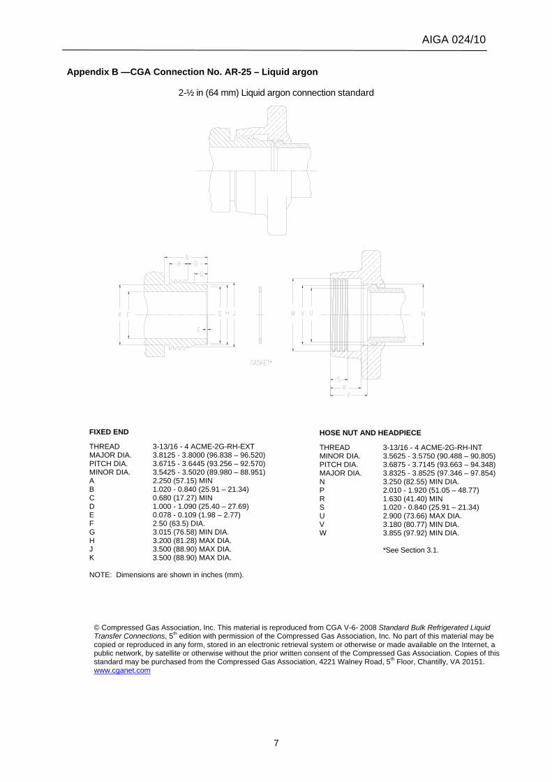
Appendix B —CGA Connection No. AR-25 – Liquid argon
2-½ in (64 mm) Liquid argon connection standard
FIXED END
THREAD 3-13/16 - 4 ACME-2G-RH-EXT MAJOR DIA. 3.8125 - 3.8000 (96.838 – 96.520) PITCH DIA. 3.6715 - 3.6445 (93.256 – 92.570) MINOR DIA. 3.5425 - 3.5020 (89.980 – 88.951) A 2.250 (57.15) MIN B 1.020 - 0.840 (25.91 – 21.34) C 0.680 (17.27) MIN D 1.000 - 1.090 (25.40 – 27.69) E 0.078 - 0.109 (1.98 – 2.77) F 2.50 (63.5) DIA. G 3.015 (76.58) MIN DIA. H 3.200 (81.28) MAX DIA. J 3.500 (88.90) MAX DIA. K 3.500 (88.90) MAX DIA. NOTE: Dimensions are shown in inches (mm).
HOSE NUT AND HEADPIECE
THREAD 3-13/16 - 4 ACME-2G-RH-INT MINOR DIA. 3.5625 - 3.5750 (90.488 – 90.805) PITCH DIA. 3.6875 - 3.7145 (93.663 – 94.348) MAJOR DIA. 3.8325 - 3.8525 (97.346 – 97.854) N 3.250 (82.55) MIN DIA. P 2.010 - 1.920 (51.05 – 48.77) R 1.630 (41.40) MIN S 1.020 - 0.840 (25.91 – 21.34) U 2.900 (73.66) MAX DIA. V 3.180 (80.77) MIN DIA. W 3.855 (97.92) MIN DIA. *See Section 3.1.
© Compressed Gas Association, Inc. This material is reproduced from CGA V-6- 2008 Standard Bulk Refrigerated Liquid Transfer Connections, 5th edition with permission of the Compressed Gas Association, Inc. No part of this material may be copied or reproduced in any form, stored in an electronic retrieval system or otherwise or made available on the Internet, a public network, by satellite or otherwise without the prior written consent of the Compressed Gas Association. Copies of this standard may be purchased from the Compressed Gas Association, 4221 Walney Road, 5th Floor, Chantilly, VA 20151. www.cganet.com
AIGA 024/10
8
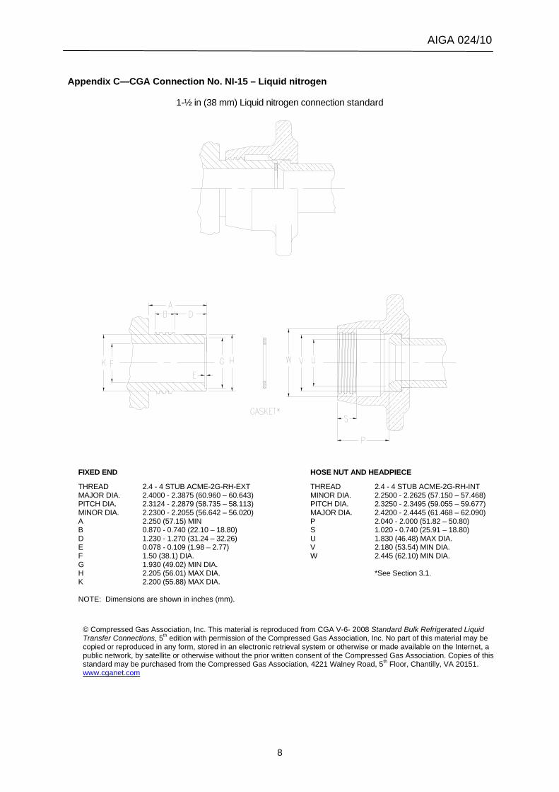
Appendix C—CGA Connection No. NI-15 – Liquid nitrogen
1-½ in (38 mm) Liquid nitrogen connection standard
FIXED END
THREAD 2.4 - 4 STUB ACME-2G-RH-EXT MAJOR DIA. 2.4000 - 2.3875 (60.960 – 60.643) PITCH DIA. 2.3124 - 2.2879 (58.735 – 58.113) MINOR DIA. 2.2300 - 2.2055 (56.642 – 56.020) A 2.250 (57.15) MIN B 0.870 - 0.740 (22.10 – 18.80) D 1.230 - 1.270 (31.24 – 32.26) E 0.078 - 0.109 (1.98 – 2.77) F 1.50 (38.1) DIA. G 1.930 (49.02) MIN DIA. H 2.205 (56.01) MAX DIA. K 2.200 (55.88) MAX DIA. NOTE: Dimensions are shown in inches (mm).
HOSE NUT AND HEADPIECE
THREAD 2.4 - 4 STUB ACME-2G-RH-INT MINOR DIA. 2.2500 - 2.2625 (57.150 – 57.468) PITCH DIA. 2.3250 - 2.3495 (59.055 – 59.677) MAJOR DIA. 2.4200 - 2.4445 (61.468 – 62.090) P 2.040 - 2.000 (51.82 – 50.80) S 1.020 - 0.740 (25.91 – 18.80) U 1.830 (46.48) MAX DIA. V 2.180 (53.54) MIN DIA. W 2.445 (62.10) MIN DIA. *See Section 3.1.
© Compressed Gas Association, Inc. This material is reproduced from CGA V-6- 2008 Standard Bulk Refrigerated Liquid Transfer Connections, 5th edition with permission of the Compressed Gas Association, Inc. No part of this material may be copied or reproduced in any form, stored in an electronic retrieval system or otherwise or made available on the Internet, a public network, by satellite or otherwise without the prior written consent of the Compressed Gas Association. Copies of this standard may be purchased from the Compressed Gas Association, 4221 Walney Road, 5th Floor, Chantilly, VA 20151. www.cganet.com
AIGA 024/10
9
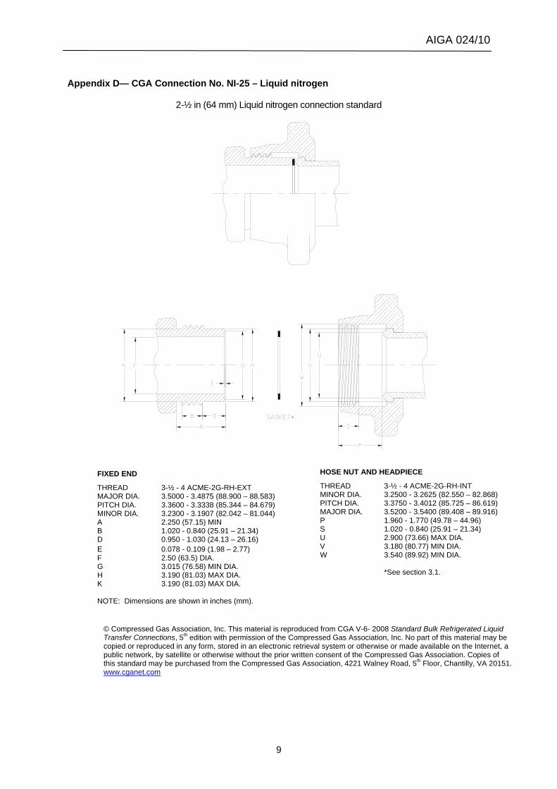
Appendix D— CGA Connection No. NI-25 – Liquid nitrogen
2-½ in (64 mm) Liquid nitrogen connection standard
FIXED END
THREAD 3-½ - 4 ACME-2G-RH-EXT MAJOR DIA. 3.5000 - 3.4875 (88.900 – 88.583) PITCH DIA. 3.3600 - 3.3338 (85.344 – 84.679) MINOR DIA. 3.2300 - 3.1907 (82.042 – 81.044) A 2.250 (57.15) MIN B 1.020 - 0.840 (25.91 – 21.34) D 0.950 - 1.030 (24.13 – 26.16) E 0.078 - 0.109 (1.98 – 2.77) F 2.50 (63.5) DIA. G 3.015 (76.58) MIN DIA. H 3.190 (81.03) MAX DIA. K 3.190 (81.03) MAX DIA. NOTE: Dimensions are shown in inches (mm).
HOSE NUT AND HEADPIECE
THREAD 3-½ - 4 ACME-2G-RH-INT MINOR DIA. 3.2500 - 3.2625 (82.550 – 82.868) PITCH DIA. 3.3750 - 3.4012 (85.725 – 86.619) MAJOR DIA. 3.5200 - 3.5400 (89.408 – 89.916) P 1.960 - 1.770 (49.78 – 44.96) S 1.020 - 0.840 (25.91 – 21.34) U 2.900 (73.66) MAX DIA. V 3.180 (80.77) MIN DIA. W 3.540 (89.92) MIN DIA. *See section 3.1.
© Compressed Gas Association, Inc. This material is reproduced from CGA V-6- 2008 Standard Bulk Refrigerated Liquid Transfer Connections, 5th edition with permission of the Compressed Gas Association, Inc. No part of this material may be copied or reproduced in any form, stored in an electronic retrieval system or otherwise or made available on the Internet, a public network, by satellite or otherwise without the prior written consent of the Compressed Gas Association. Copies of this standard may be purchased from the Compressed Gas Association, 4221 Walney Road, 5th Floor, Chantilly, VA 20151. www.cganet.com
AIGA 024/10
10
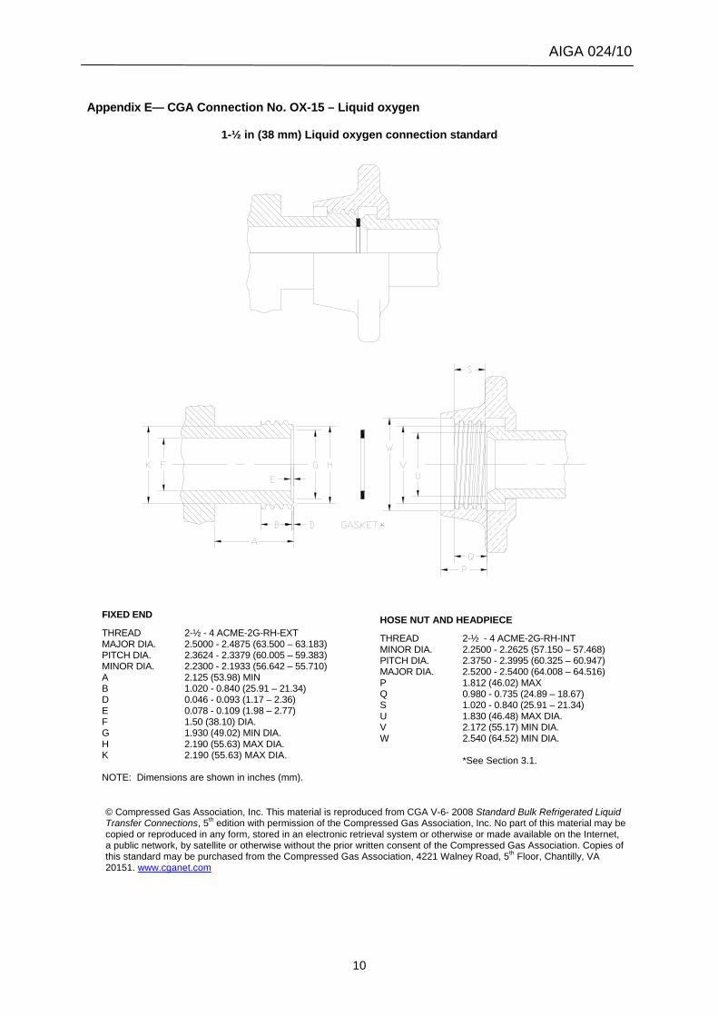
Appendix E— CGA Connection No. OX-15 – Liquid oxygen
1-½ in (38 mm) Liquid oxygen connection standard
FIXED END
THREAD 2-½ - 4 ACME-2G-RH-EXT MAJOR DIA. 2.5000 - 2.4875 (63.500 – 63.183) PITCH DIA. 2.3624 - 2.3379 (60.005 – 59.383) MINOR DIA. 2.2300 - 2.1933 (56.642 – 55.710) A 2.125 (53.98) MIN B 1.020 - 0.840 (25.91 – 21.34) D 0.046 - 0.093 (1.17 – 2.36) E 0.078 - 0.109 (1.98 – 2.77) F 1.50 (38.10) DIA. G 1.930 (49.02) MIN DIA. H 2.190 (55.63) MAX DIA. K 2.190 (55.63) MAX DIA. NOTE: Dimensions are shown in inches (mm).
HOSE NUT AND HEADPIECE
THREAD 2-½ - 4 ACME-2G-RH-INT MINOR DIA. 2.2500 - 2.2625 (57.150 – 57.468) PITCH DIA. 2.3750 - 2.3995 (60.325 – 60.947) MAJOR DIA. 2.5200 - 2.5400 (64.008 – 64.516) P 1.812 (46.02) MAX Q 0.980 - 0.735 (24.89 – 18.67) S 1.020 - 0.840 (25.91 – 21.34) U 1.830 (46.48) MAX DIA. V 2.172 (55.17) MIN DIA. W 2.540 (64.52) MIN DIA. *See Section 3.1.
© Compressed Gas Association, Inc. This material is reproduced from CGA V-6- 2008 Standard Bulk Refrigerated Liquid Transfer Connections, 5th edition with permission of the Compressed Gas Association, Inc. No part of this material may be copied or reproduced in any form, stored in an electronic retrieval system or otherwise or made available on the Internet, a public network, by satellite or otherwise without the prior written consent of the Compressed Gas Association. Copies of this standard may be purchased from the Compressed Gas Association, 4221 Walney Road, 5th Floor, Chantilly, VA 20151. www.cganet.com
AIGA 024/10
11
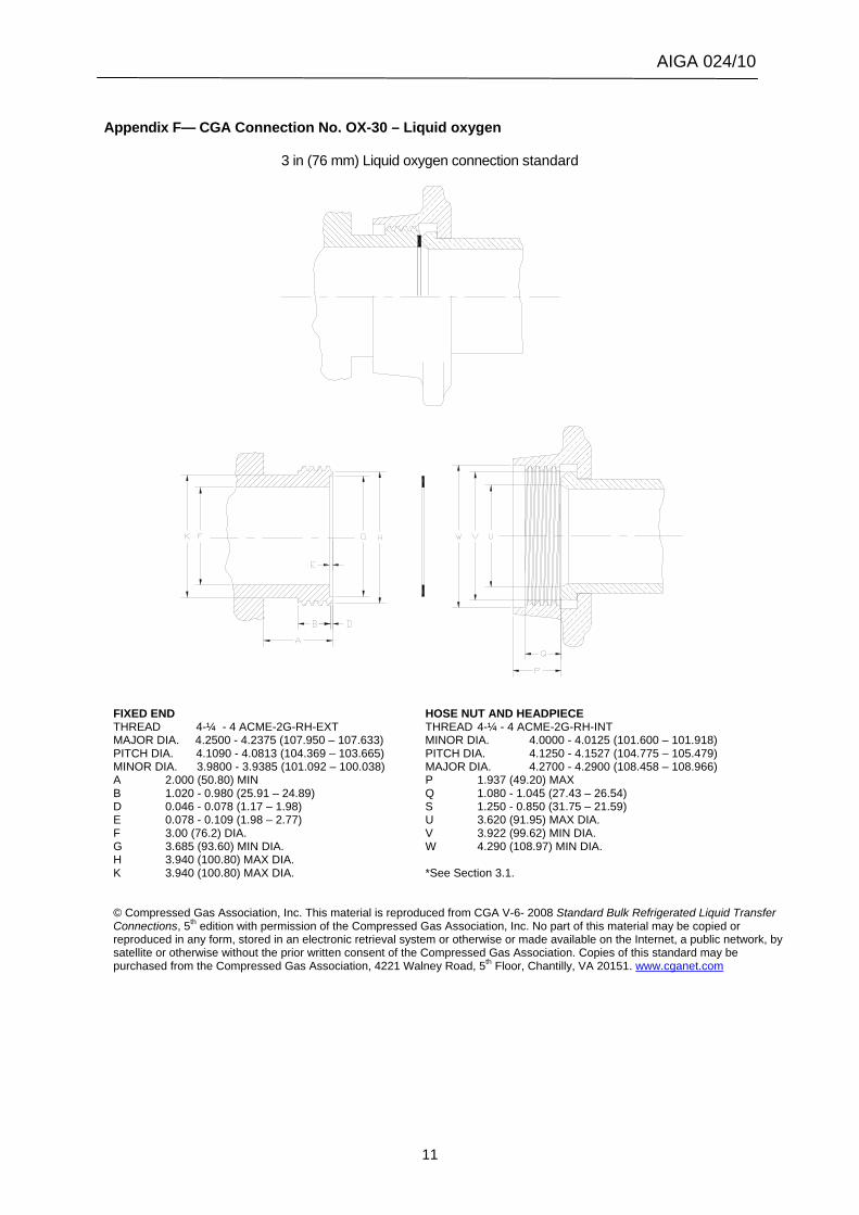
Appendix F— CGA Connection No. OX-30 – Liquid oxygen
3 in (76 mm) Liquid oxygen connection standard
FIXED END HOSE NUT AND HEADPIECE THREAD 4-¼ - 4 ACME-2G-RH-EXT THREAD 4-¼ - 4 ACME-2G-RH-INT MAJOR DIA. 4.2500 - 4.2375 (107.950 – 107.633) MINOR DIA. 4.0000 - 4.0125 (101.600 – 101.918) PITCH DIA. 4.1090 - 4.0813 (104.369 – 103.665) PITCH DIA. 4.1250 - 4.1527 (104.775 – 105.479) MINOR DIA. 3.9800 - 3.9385 (101.092 – 100.038) MAJOR DIA. 4.2700 - 4.2900 (108.458 – 108.966) A 2.000 (50.80) MIN P 1.937 (49.20) MAX B 1.020 - 0.980 (25.91 – 24.89) Q 1.080 - 1.045 (27.43 – 26.54) D 0.046 - 0.078 (1.17 – 1.98) S 1.250 - 0.850 (31.75 – 21.59) E 0.078 - 0.109 (1.98 – 2.77) U 3.620 (91.95) MAX DIA. F 3.00 (76.2) DIA. V 3.922 (99.62) MIN DIA. G 3.685 (93.60) MIN DIA. W 4.290 (108.97) MIN DIA. H 3.940 (100.80) MAX DIA. K 3.940 (100.80) MAX DIA. *See Section 3.1. © Compressed Gas Association, Inc. This material is reproduced from CGA V-6- 2008 Standard Bulk Refrigerated Liquid Transfer Connections, 5th edition with permission of the Compressed Gas Association, Inc. No part of this material may be copied or reproduced in any form, stored in an electronic retrieval system or otherwise or made available on the Internet, a public network, by satellite or otherwise without the prior written consent of the Compressed Gas Association. Copies of this standard may be purchased from the Compressed Gas Association, 4221 Walney Road, 5th Floor, Chantilly, VA 20151. www.cganet.com
AIGA 024/10
12
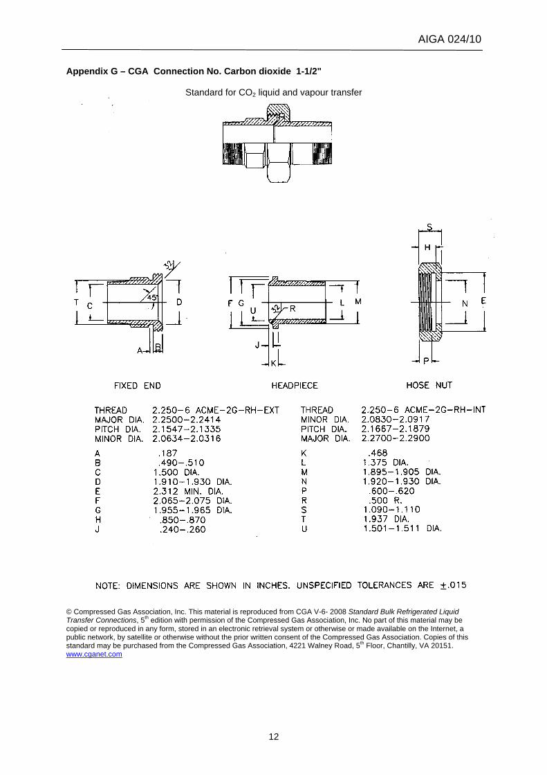
Appendix G – CGA Connection No. Carbon dioxide 1-1/2"
Standard for CO2 liquid and vapour transfer
© Compressed Gas Association, Inc. This material is reproduced from CGA V-6- 2008 Standard Bulk Refrigerated Liquid Transfer Connections, 5th edition with permission of the Compressed Gas Association, Inc. No part of this material may be copied or reproduced in any form, stored in an electronic retrieval system or otherwise or made available on the Internet, a public network, by satellite or otherwise without the prior written consent of the Compressed Gas Association. Copies of this standard may be purchased from the Compressed Gas Association, 4221 Walney Road, 5th Floor, Chantilly, VA 20151. www.cganet.com
AIGA 024/10
13
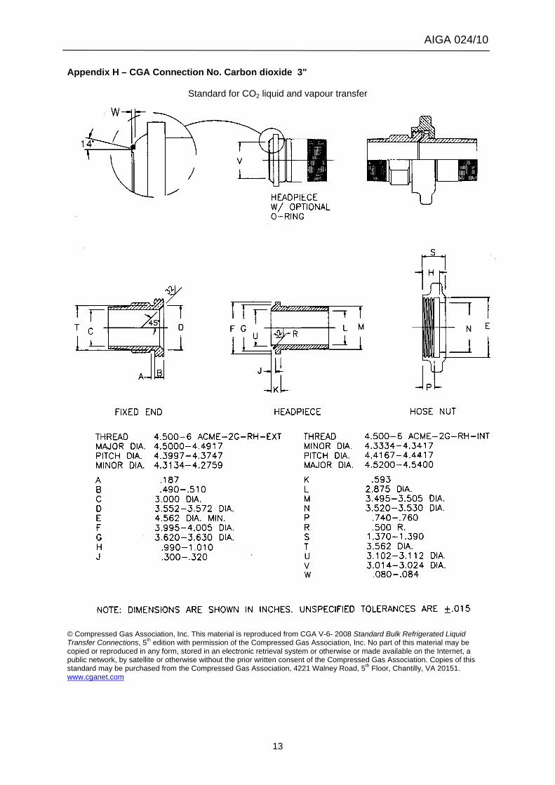
Appendix H – CGA Connection No. Carbon dioxide 3"
Standard for CO2 liquid and vapour transfer
© Compressed Gas Association, Inc. This material is reproduced from CGA V-6- 2008 Standard Bulk Refrigerated Liquid Transfer Connections, 5th edition with permission of the Compressed Gas Association, Inc. No part of this material may be copied or reproduced in any form, stored in an electronic retrieval system or otherwise or made available on the Internet, a public network, by satellite or otherwise without the prior written consent of the Compressed Gas Association. Copies of this standard may be purchased from the Compressed Gas Association, 4221 Walney Road, 5th Floor, Chantilly, VA 20151. www.cganet.com
AIGA 024/10
14
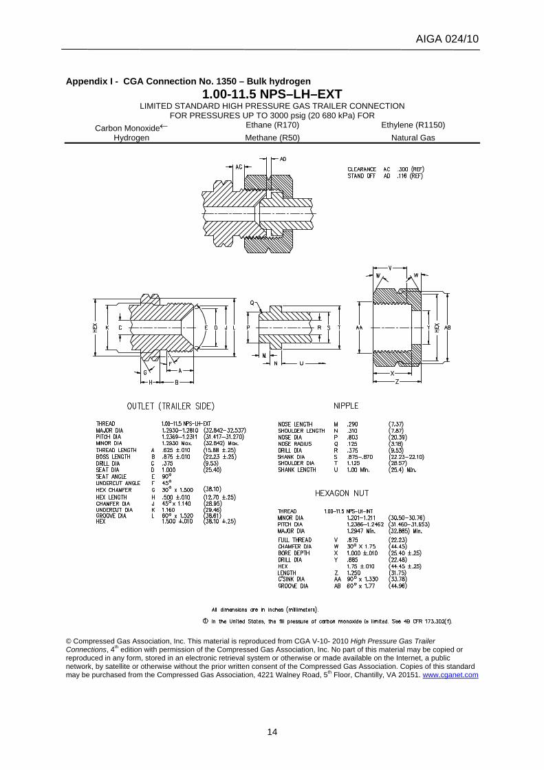
Appendix I - CGA Connection No. 1350 – Bulk hydrogen
1.00-11.5 NPS–LH–EXT LIMITED STANDARD HIGH PRESSURE GAS TRAILER CONNECTION
FOR PRESSURES UP TO 3000 psig (20 680 kPa) FOR Carbon Monoxide← Ethane (R170) Ethylene (R1150)
Hydrogen Methane (R50) Natural Gas
© Compressed Gas Association, Inc. This material is reproduced from CGA V-10- 2010 High Pressure Gas Trailer Connections, 4th edition with permission of the Compressed Gas Association, Inc. No part of this material may be copied or reproduced in any form, stored in an electronic retrieval system or otherwise or made available on the Internet, a public network, by satellite or otherwise without the prior written consent of the Compressed Gas Association. Copies of this standard may be purchased from the Compressed Gas Association, 4221 Walney Road, 5th Floor, Chantilly, VA 20151. www.cganet.com
AIGA 024/10
15
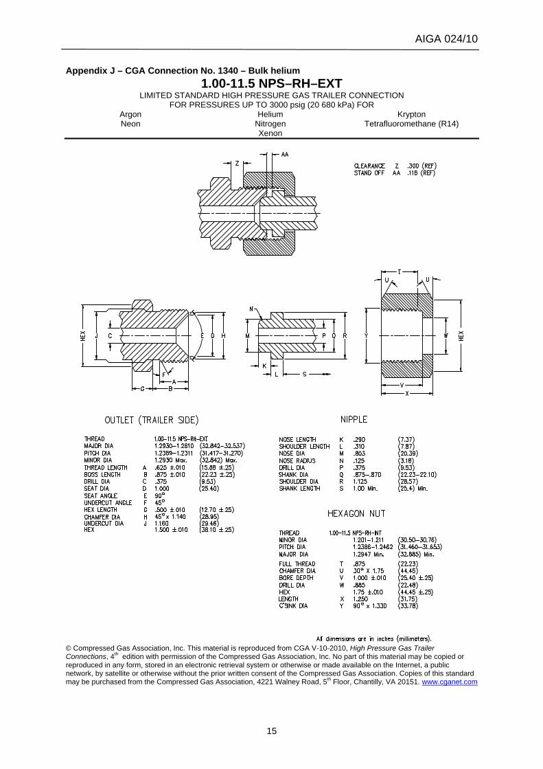
Appendix J – CGA Connection No. 1340 – Bulk helium 1.00-11.5 NPS–RH–EXT
LIMITED STANDARD HIGH PRESSURE GAS TRAILER CONNECTION FOR PRESSURES UP TO 3000 psig (20 680 kPa) FOR
Argon Helium Krypton Neon Nitrogen Tetrafluoromethane (R14)
Xenon
© Compressed Gas Association, Inc. This material is reproduced from CGA V-10-2010, High Pressure Gas Trailer Connections, 4th edition with permission of the Compressed Gas Association, Inc. No part of this material may be copied or reproduced in any form, stored in an electronic retrieval system or otherwise or made available on the Internet, a public network, by satellite or otherwise without the prior written consent of the Compressed Gas Association. Copies of this standard may be purchased from the Compressed Gas Association, 4221 Walney Road, 5th Floor, Chantilly, VA 20151. www.cganet.com
AIGA 024/10
16
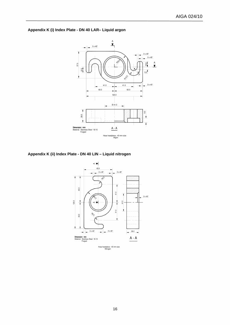
Appendix K (i) Index Plate - DN 40 LAR– Liquid argon
Appendix K (ii) Index Plate - DN 40 LIN – Liquid nitrogen
AIGA 024/10
17
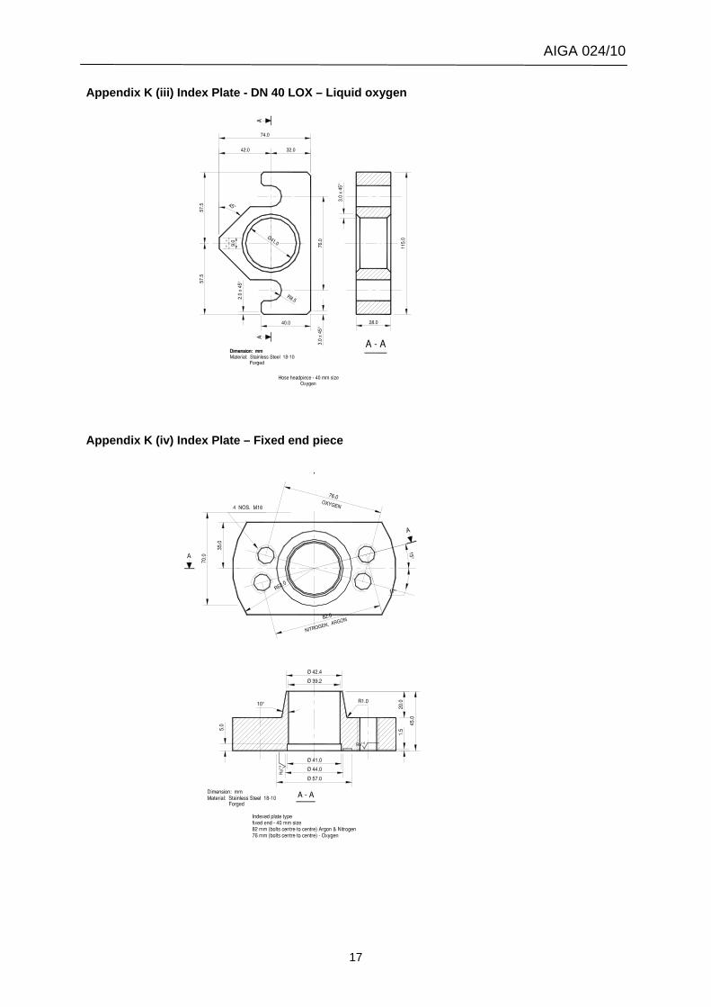
Appendix K (iii) Index Plate - DN 40 LOX – Liquid oxygen
Appendix K (iv) Index Plate – Fixed end piece
AIGA 024/10
18
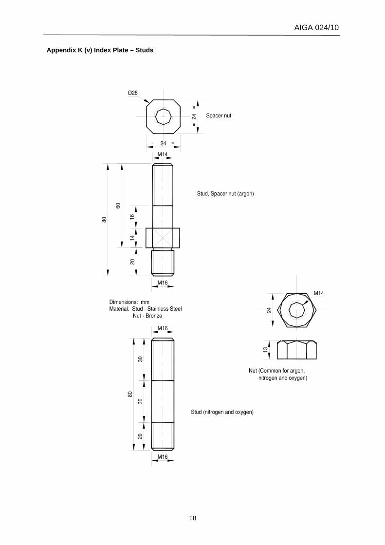
Appendix K (v) Index Plate – Studs
AIGA 024/10
19
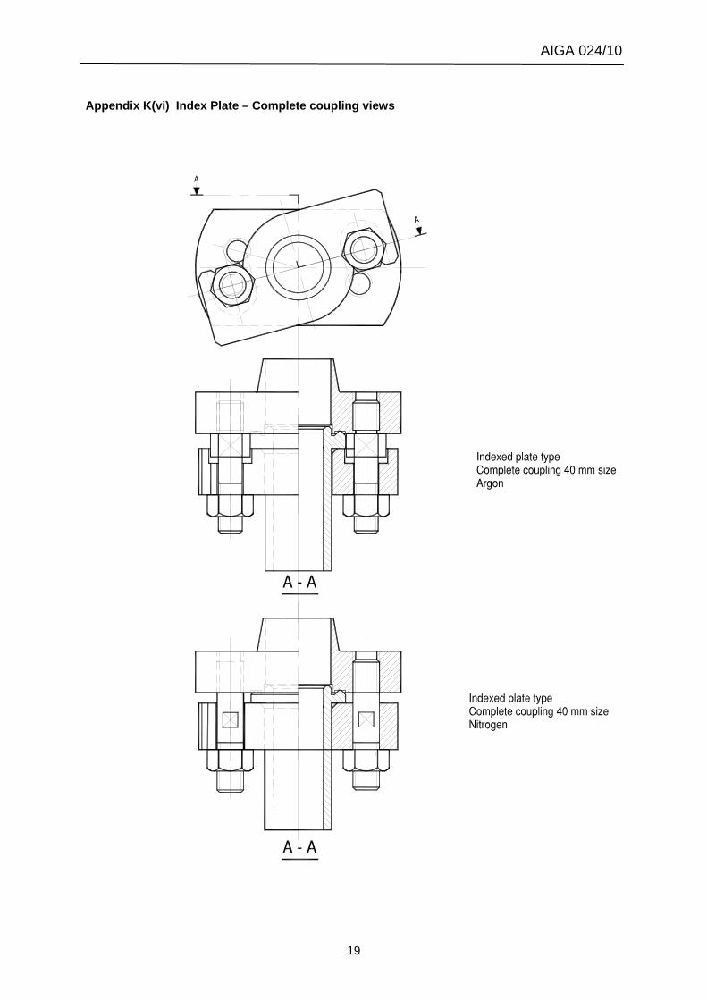
Appendix K(vi) Index Plate – Complete coupling views
AIGA 024/10
20
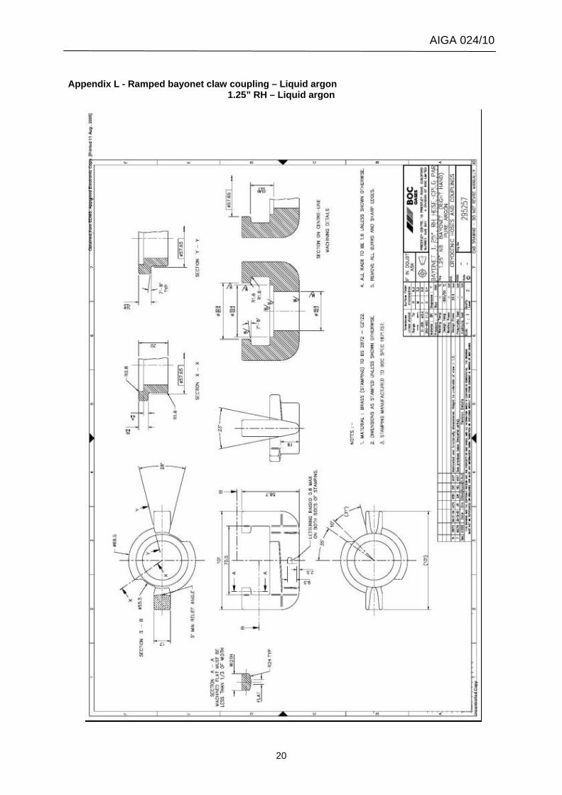
Appendix L - Ramped bayonet claw coupling – Liquid argon
1.25” RH – Liquid argon
AIGA 024/10
21
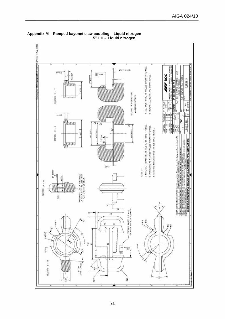
Appendix M – Ramped bayonet claw coupling – Liquid nitrogen
1.5’’ LH - Liquid nitrogen
AIGA 024/10
22
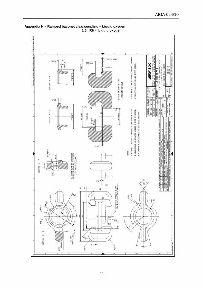
Appendix N – Ramped bayonet claw coupling – Liquid oxygen 1.5’’ RH - Liquid oxygen
AIGA 024/10
23
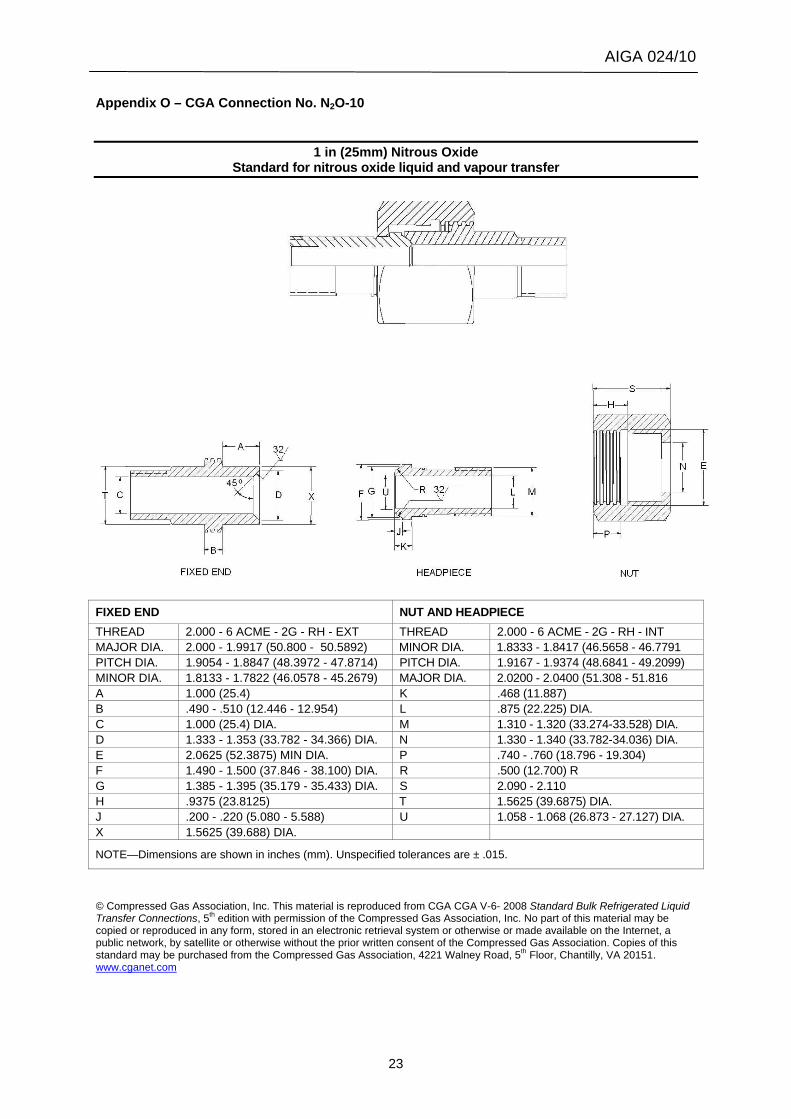
Appendix O – CGA Connection No. N2O-10
1 in (25mm) Nitrous Oxide Standard for nitrous oxide liquid and vapour transfer
FIXED END NUT AND HEADPIECE THREAD 2.000 - 6 ACME - 2G - RH - EXT THREAD 2.000 - 6 ACME - 2G - RH - INT MAJOR DIA. 2.000 - 1.9917 (50.800 - 50.5892) MINOR DIA. 1.8333 - 1.8417 (46.5658 - 46.7791 PITCH DIA. 1.9054 - 1.8847 (48.3972 - 47.8714) PITCH DIA. 1.9167 - 1.9374 (48.6841 - 49.2099) MINOR DIA. 1.8133 - 1.7822 (46.0578 - 45.2679) MAJOR DIA. 2.0200 - 2.0400 (51.308 - 51.816 A 1.000 (25.4) K .468 (11.887) B .490 - .510 (12.446 - 12.954) L .875 (22.225) DIA. C 1.000 (25.4) DIA. M 1.310 - 1.320 (33.274-33.528) DIA. D 1.333 - 1.353 (33.782 - 34.366) DIA. N 1.330 - 1.340 (33.782-34.036) DIA. E 2.0625 (52.3875) MIN DIA. P .740 - .760 (18.796 - 19.304) F 1.490 - 1.500 (37.846 - 38.100) DIA. R .500 (12.700) R G 1.385 - 1.395 (35.179 - 35.433) DIA. S 2.090 - 2.110 H .9375 (23.8125) T 1.5625 (39.6875) DIA. J .200 - .220 (5.080 - 5.588) U 1.058 - 1.068 (26.873 - 27.127) DIA. X 1.5625 (39.688) DIA.
NOTE—Dimensions are shown in inches (mm). Unspecified tolerances are ± .015.
© Compressed Gas Association, Inc. This material is reproduced from CGA CGA V-6- 2008 Standard Bulk Refrigerated Liquid Transfer Connections, 5th edition with permission of the Compressed Gas Association, Inc. No part of this material may be copied or reproduced in any form, stored in an electronic retrieval system or otherwise or made available on the Internet, a public network, by satellite or otherwise without the prior written consent of the Compressed Gas Association. Copies of this standard may be purchased from the Compressed Gas Association, 4221 Walney Road, 5th Floor, Chantilly, VA 20151. www.cganet.com
AIGA 024/10
24
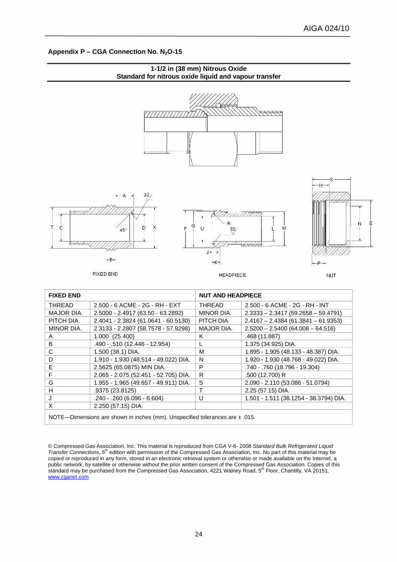
Appendix P – CGA Connection No. N2O-15
1-1/2 in (38 mm) Nitrous Oxide Standard for nitrous oxide liquid and vapour transfer
FIXED END NUT AND HEADPIECE THREAD 2.500 - 6 ACME - 2G - RH - EXT THREAD 2.500 - 6 ACME - 2G - RH - INT MAJOR DIA. 2.5000 - 2.4917 (63.50 - 63.2892) MINOR DIA. 2.3333 – 2.3417 (59.2658 – 59.4791) PITCH DIA. 2.4041 - 2.3824 (61.0641 - 60.5130) PITCH DIA. 2.4167 – 2.4384 (61.3841 – 61.9353) MINOR DIA. 2.3133 - 2.2807 (58.7578 - 57.9298) MAJOR DIA. 2.5200 – 2.5400 (64.008 – 64.516) A 1.000 (25.400) K .468 (11.887) B .490 - .510 (12.446 - 12.954) L 1.375 (34.925) DIA. C 1.500 (38.1) DIA. M 1.895 - 1.905 (48.133 - 48.387) DIA. D 1.910 - 1.930 (48.514 - 49.022) DIA. N 1.920 - 1.930 (48.768 - 49.022) DIA. E 2.5625 (65.0875) MIN DIA. P .740 - .760 (18.796 - 19.304) F 2.065 - 2.075 (52.451 - 52.705) DIA. R .500 (12.700) R G 1.955 - 1.965 (49.657 - 49.911) DIA. S 2.090 - 2.110 (53.086 - 51.0794) H .9375 (23.8125) T 2.25 (57.15) DIA. J .240 - .260 (6.096 - 6.604) U 1.501 - 1.511 (38.1254 - 38.3794) DIA. X 2.250 (57.15) DIA.
NOTE—Dimensions are shown in inches (mm). Unspecified tolerances are ± .015.
© Compressed Gas Association, Inc. This material is reproduced from CGA V-6- 2008 Standard Bulk Refrigerated Liquid Transfer Connections, 5th edition with permission of the Compressed Gas Association, Inc. No part of this material may be copied or reproduced in any form, stored in an electronic retrieval system or otherwise or made available on the Internet, a public network, by satellite or otherwise without the prior written consent of the Compressed Gas Association. Copies of this standard may be purchased from the Compressed Gas Association, 4221 Walney Road, 5th Floor, Chantilly, VA 20151. www.cganet.com