Embed Size (px)
Citation preview
Spring 2012 | Volume 17 Issue 2
Photoreactive Nanofiber Scaffolds continued on Page 2
SurFACTS in Biomaterials
Pg. 1: Photoreactive Nanofiber Scaffolds for Tissue EngineeringBy Eric Guire and Bob Hanson,Innovative Surface Technologies, Inc (ISurTec)
Pg. 4: Pluripotent Stem Cell Cultures Using Synthetic PolymersBy Aftin Ross and Joerg Lahann, University of Michigan
Pg. 5: Surface Science Calendar of Events
Pg. 6: Controlled Release of Nitric Oxide and Drugs for Biomedical and Pharmaceutical ApplicationsBy Rao S Bezwada, Bezwada Biomedical LLC
Pg. 10: Post-Grant ProceedingsBy Colin Fairman, JD, PhD, Intellectual Property and Legal Editor
Pg. 14: FDA Issues Final Guidance on Benefit-Risk DeterminationsBy Phil Triolo, SurFACTS Regulatory Editor
Pg. 15: Electron Microscopy of Biomaterials-Tissue InterfacesBy Alexandra Porter, Dept. Materials, Imperial College London
Pg. 19: Surfaces in Biomaterials Supporting Members
Inside this Issue
Members are encouraged to submit articles for future editions of SurFACTS. Please e-mail your report (with all appropriate figures and graphics) to Staff Editor Cody Zwiefelhofer at [email protected] for consideration in a future issue. Deadlines for upcoming issues are posted on surfaces.org.
Photoreactive Nanofiber Scaffolds for Tissue Engineering
By Eric Guire and Bob Hanson,Innovative Surface Technologies, Inc (ISurTec)
Tissue engineering promises to change medical practice profoundly, creating improved treatments, enhancing quality of life and even overcoming the constant shortage of donor organs for transplantation. Expectations are also high regarding the potential markets for the products created through tissue engineering techniques, with estimates ranging from $6 billion to $600 billion per year worldwide1.
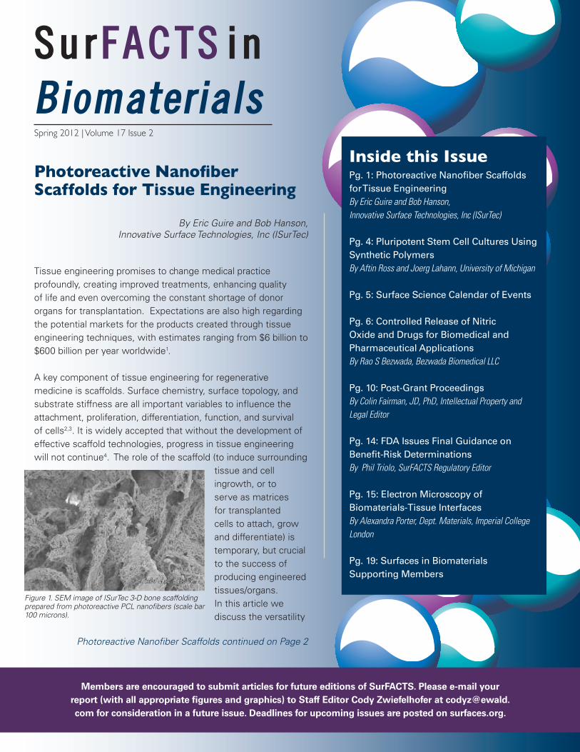
A key component of tissue engineering for regenerative medicine is scaffolds. Surface chemistry, surface topology, and substrate stiffness are all important variables to influence the attachment, proliferation, differentiation, function, and survival of cells2,3. It is widely accepted that without the development of effective scaffold technologies, progress in tissue engineering will not continue4. The role of the scaffold (to induce surrounding
tissue and cell ingrowth, or to serve as matrices for transplanted cells to attach, grow and differentiate) is temporary, but crucial to the success of producing engineered tissues/organs. In this article we discuss the versatility
Figure 1. SEM image of ISurTec 3-D bone scaffolding prepared from photoreactive PCL nanofibers (scale bar 100 microns).

2
Photoreactive Nanofiber Scaffolds continued from Page 1
Photoreactive Nanofiber Scaffolds Continued on Page 3
of photoreactive nanofiber technology for tissue engineering scaffolds: the incorporation of latent reactive photogroups within nanofibers can be used both to tune the mechanical properties of the scaffold and to add functionality to the scaffold surface.
There’s no place like bone
The creation of a supportive and familiar “nest” for nascent bone in vivo is a high-value proposition. In 2004, the US Healthcare and Utilization Project estimated that more than 1.1 million surgical procedures involving the partial excision of bone, bone grafting, and inpatient fracture repair were performed at an estimated total cost of more than $5 billion5. Currently these surgical procedures may incorporate autograft bone, allograft bone, metals and/or ceramics. The procedures are cumbersome, expensive, and have complication rates exceeding 30%. These serious drawbacks may be overcome with the use of improved synthetic tissue engineering scaffolds6. In 2001, Frost and Sullivan estimated that the total US market for bone scaffolds would exceed $1.3 billion in 20067.
An ideal bone regeneration scaffold is biocompatible, biodegradable, porous, strong yet flexible, and easily prepared in different shapes. The material should possess sufficient mechanical strength and flexibility to mimic trabecular bone and sufficient porosity to enable cell colonization, exchange of nutrients, and vascularization6, as well as provide chemical and nanotopological cues to promote efficient osteogenesis. It is also preferable that it be degraded or resorbed by the body after it has performed its temporary functions.
To these aims, we used electrospun photoreactive polycaprolactone (PCL) nanofibers (patent pending) as a starting material to fabricate 3-dimensional bone scaffoldings in the presence of a poragen. The scaffoldings were fused using a relatively low-temperature sintering process. In this manner, photoreactive nanofiber mats could be fashioned into mechanically robust, porous scaffoldings ready for biomolecule functionalization and possessing a nanotopology that mimics natural extracellular matrix (Fig 1).
Mechanical properties
The mechanical properties of a bone replacement material, such as compressive modulus and compressive strength, are important in their own right but also can significantly influence osteogenesis8. Our use of photoreactive nanofibers enabled us to tune the mechanical properties of the scaffold by varying the degree of photocrosslinking. This parameter strongly influenced the resulting physical properties of the nanofibers, such as melting point and stiffness. Indeed, we found the compressive modulus of our PCL scaffolds could be tailored over a range wider than that represented by native bone (50-1000 MPa). Our electrospun PCL nanofibers contain photogroups on the surface as well as within the fibers. Most hydrocarbon-based materials can be quickly and reliably immobilized to a photochemical surface
Figure 2. Research-grade photoreactive PCL bone scaffolding shown after processing into a disc wafer (left), and wafer easily supporting a 1kg weight (right).
SurFACTS in Biomaterials is the official publication of the foundation and is dedicated to serving industrial engineers, research scientists, and academicians working in the field of biomateri-als, biomedical devices, or diagnostic research.
Foundation Officers
Dan Hook, PresidentBausch & Lomb1400 North Goodman StreetPO Box 30450Rochester, NY 14609-0450Telephone (585) 338-6580Peter Edelman, President-Elect Boston Scientific3 Scimed PlaceMaple Grove, MN 55311Telephone (763) 255-0282John O’Donoghue, Vice PresidentEnBIO Ltd.Rubicon CentreCIt CampusCork, IrelandTelephone +35315253305John Fisher, SecretaryW.L. Gore & Associates3250 West Kiltie LaneFlagstaff, AZ 86001Telephone (928) 864-3506Lawrence Salvati, TreasurerDePuy Orthopaedics700 Orthopaedic DriveWarsaw, IN 46581Telephone (574) 372-7220Marc Hendriks, Past PresidentDSM Biomedical P.O. Box 186160 MD GeleenThe NetherlandsTelephone +31464760278
Committee Chairs
MembershipRobert Kellar and Jeannette PolkinghorneBioInterface 2012 ProgramMarc HendriksBioInterface 2012 WorkshopJeannette PolkinghorneAwardsJeannette Polkinghorne
Foundation Office Staff
Andy Shelp, Executive Director1000 Westgate Drive, Suite 252St. Paul, MN 55114Telephone (847) 977-6153 Fax (651) 290-2266Email: [email protected]
SurFACTS in Biomaterials Editors
Executive EditorJoe McGonigleSurModics, [email protected]
Staff EditorCody ZwiefelhoferEwald [email protected]
Intellectual Property and Legal EditorColin Fairman, JD, Ph. D.Fulbright & [email protected]
Biomaterials EditorMelissa Reynolds, Ph. D.Colorado State [email protected]
Surface Characterization and Analysis EditorBill [email protected]
Regulatory EditorPhil TrioloPhil Triolo & Associates [email protected]
Advertising ManagerEwald [email protected]
© 2012 published by theSurfaces in Biomaterials Foundation.
All rights reserved.

to produce excellent coverage. Due to the limits of UV penetration in 3-dimensional scaffolds, however, functional groups were introduced to the nanofiber mats prior to their processing into scaffolds. In this example, photoreactive PCL nanofiber mats were conjugated to polyacrylic acid upon brief exposure to ultraviolet light, resulting in a high degree of surface carboxylation.
Growth factor immobilization
Bone Morphogenic Protein 2 (BMP-2) is a growth factor in the TGF-ß superfamily. BMP-2 is used in the orthopedic field to facilitate osteogenesis in anterior lumbar interbody fusions and acute open tibia fractures, and has additional off-label uses. Medical applications of BMP-2, which is highly soluble, employ the use of a carrier to achieve a local residence time of 2-8 days9. However, immobilization can improve the stability and persistence of growth factors, producing highly localized effects while using much less of these costly proteins10. Therefore, we immobilized BMP-2 to the nanofiber surfaces throughout the scaffold and assessed its ability to promote bone formation. Indeed, our BMP-2-modified scaffolds were able to initiate and maintain osteogenesis out to at least 2 weeks in vitro (Fig 3). In this example, BMP-2 was conjugated to carboxylated mini-scaffolds using
a chemical coupling procedure. Scaffolds were then seeded with mesenchymal stem cells (MSCs) by injection, and placed in culture. The cultures were assayed for alkaline phosphatase (ALP), a marker of bone formation, at the indicated time points.
As mentioned above, the potential revenues to be realized from successful tissue engineering products are quite large. A report written for NSF by Abt Associates in 2003 estimated that over $600 million was being spent annually by some 70 start-ups and business units on tissue engineering research globally11, and the amount today is surely much greater. Successful technologies will meet the needs of researchers, medical professionals, patients and insurers, as well as obtain governmental regulatory approval prior to use in humans or animals.
*This work was supported by SBIR grant #005905 from NIBIB, PI Jie Wen, PhD.
REFERENCES
1. Bock, A., Ibarreta, D., Rodrigues-Cerezo, E. Human tissue-engineered products. European Commission Directorate-General Joint Research Centre (2003).
2. Di Martino A, Liverani L, Rainer A, Salvatore G, Trombetta M, Denaro V. Electrospun scaffolds for bone
tissue engineering. Musculoskelet Surg. 2011 Aug;95(2):69-80.
3. Schindler M, Nur-E-Kamal A, Ahmed I, Kamal J, Liu HY, Amor N, Ponery AS, Crockett DP, Grafe TH, Chung HY, Weik T, Jones E, Meiners S. Living in three dimensions: 3D nanostructured environments for cell culture and regenerative medicine. Cell Biochem Biophys. 2006;45(2):215-27.
4. Simone, R. Growing old, staying young. European Patent Office. www.epo.org/focus/innnovation-and-economy/emerging-technologies/article-x.html
5. US Healthcare Cost and Utilization Project Nationwide Inpatient Statistics (2004).
6. Venugopal, J., Vadgama, V., Sampath Kumar, T., Ramakrishma, S. Biocomposite nanofibers and osteoblasts for bone tissue engineering. Nanotechnology. 2007;18:1-7.
7. US Tissue Engineering Market. Frost & Sullivan (2001).
8. Kelly DJ, Jacobs CR. The role of mechanical signals in regulating chondrogenesis and osteogenesis of mesenchymal stem cells. Birth Defects Res C Embryo Today. 2010 Mar;90(1):75-85.
9. Valdes MA, Thakur NA, Namdari S, Ciombor DM, Palumbo M. Recombinant bone morphogenic protein-2 in orthopaedic surgery: a review. Arch Orthop Trauma Surg. 2009 Dec;129(12):1651-7.
10. Masters KS. Covalent growth factor immobilization strategies for tissue repair and regeneration. Macromol Biosci. 2011 Sep 9;11(9):1149-63.
11. Viola, J., Lal, B., Grad, O. The emergence of tissue engineering as a research field. National Science Foundation Report #EEC-9815425. Abt Associates Inc. (2003).
Photoreactive Nanofiber Scaffolds Continued from Page 2
3
Figure 3. (Left) ALP production by seeded scaffolds as measured by PNPP assay. (Right) live calcein staining of nascent bone, indicating the presence of healthy cells.

Introduction
Researchers at the University of Michigan have developed a synthetic stem cell culture system based on a zwitterionic hydrogel that has shown efficacy in the long-term culture of human embryonic stem cells (hESCs) and in the forced derivation of human induced pluripotent stem cells (hIPSCs). These cells are a type of human pluripotent stem cell (hPSC), which means they have the ability to differentiate into all cell types depending on the cues provided in the cellular microenvironment. Stem cells have a host of applications in therapeutics and regenerative medicine. However, clinical adoption is hindered by immunogenic concerns as a result of the use of xenogenous factors or feeder layers in standard hPSC culture. Utilizing synthetic substrates addresses this major concern.
Clinical need for synthetic substrates
Standard hPSC culture utilizes mouse embryonic fibroblasts (mEFs) or a gelatinous protein mix called MatrigelTM, which is generated by mouse cancer cells. In addition to immunogenic concerns, these culture systems also exhibit batch-batch variation and are not compatible with large scale cell expansion.1 This is significant, because a large number of stem cells are needed for a given therapeutic application. Synthetic culture substrates address many of these limitations. In particular, our group has investigated the use of hydrogels as a platform for the long-term culture of hPSCs.
Hydrogels as synthetic cell culture substrates
Specifically, we investigated the ability of six methacrylate derivatives to
maintain hESCs in the undifferentiated state in prolonged culture.2 For this analysis, the following hydrogels were coated on tissue culture plastic via surface-initiated graft polymerization: 1.poly[carboxybetaine methacrylate] (PCBMA) 2.poly[[2-(methacryloyloxy)ethyl]trimethylammonium chloride] (PMETAC) 3.poly[poly(ethylene glycol) methyl ether methacrylate] (PPEGMA) 4.poly[2-hydroxyethyl methacrylate] (PHEMA) 5.poly[3-sulfopropyl methacrylate] (PSPMA) 6.poly[2-(methacryloyloxy)ethyl dimethyl-(3-sulfopropyl)ammonium hydroxide] (PMEDSAH). Hydrogels were characterized in terms of their material properties (wettability, hardness, chemical structure) and by the hESC adhesion and maintenance on the surfaces (Figure 1).
Storage and sterility also influence clinical use and adoption of cell culture substrates. Thus the structure and composition of PMEDSAH was
Pluripotent Stem Cell Cultures Using Synthetic PolymersBy Aftin Ross and Joerg Lahann, University of Michigan, Departments of Biomedical Engineering, Chemical
Engineering, Materials Science and Engineering, and Macromolecular Science and Engineering
4
Figure 1: Long-term culture of H9 hESCs on methacrylate-derivative coatings with mouse embryonic fibroblast (MEF)-conditioned media. Table provides information about substrate properties [contact angle, reduced elastic modulus (GPa) (mean ± s.d.)] and cell behavior [initial hESC aggregate adhesion (mean ± s.e.m.) and number of passages achieved] on each polymer coating. Of these, only the zwitterionic PMEDSAH maintained hESCs in the undifferentiated state for long-term passage as evidenced by gene expression, karyotype, and embryoid body formation. This initial study used embryonic fibroblast-conditioned media (MEF-CM), and subsequent studies utilized a media that did not contain any non-human products and serum-free media which are more clinically relevant. Under these conditions hESCs were maintained for 15 and 10 passages in xeno-free and serum-free media respectively. The applicability of a synthetic substrate for stem cell culture would be enhanced if it was compatible with multiple stem cell types. Recently, we demonstrated long-term culture (passage number 15) of human induced pluripotent stem cells (hIPSCs) on PMEDSAH in a defined media, human cell-conditioned media (hCCM).3
Pluripotent Stem Cell Cultures Continued on Page 9

55
Surface Science Calendar of Events
EuroPCR 2012May 15-18, 2012Paris, France http://www.europcr.com/page/europcr/9-course-concept.html
Biointerface Science Gordon Research Seminar and Conference
May 19-25, 2012Les Diablerets, Switzerlandhttp://www.grc.org/meetings.aspx?year=2012
Medical Device and ManufacturingEast (MD&M East)
May 22-24, 2012Philadelphia, PAhttp://www.canontradeshows.com/expo/east11/
World Biomaterials CongressJune 1-5, 2012Chengdu, Chinahttp://www.wbc2012.com
SBE’s 6th International Conference on Bioengineering and Nanotechnology (ICBN)
June 24-27, 2012University of California at Berkeley, CAhttp://icbn.aiche.org/
Surface Characterization of Biomaterials -2012 Annual NESAC/BIO Workshop
August 13-15, 2012Seattle, WAhttp://www.nb.uw.edu/home/workshop/
3rd TERMIS World Congress 2012September 5-8, 2012Vienna, Austriahttp://www.wc2012-vienna.org/
Innovations in Biomedical Materials 2012September 10-13, 2012Raleigh, NChttp://ceramics.org/meetings/innovations-in-biomedical-materials-2012
BioInterface 2012October 23-25, 2012Dublin, Irelandhttp://www.BioInterface2012Ireland.com
AIChE 2012 Annual MeetingOctober 28-November 2, 2012Pittsburgh, PAhttp://www.aiche.org/Conferences/AnnualMeeting/index.aspx
5
INTERFACE2012BIO

6
We have developed a portfolio of new nitric oxide (NO) and drug releasing macromers, oligomers and polymers for controlled release applications. These NO and drug releasing macromers and oligomers are comprised of a drug molecule and a NO releasing moiety linked to each other via a hydrolytically degradable linker as shown in figure 1 below.
Key features and benefits of these NO and drug releasing macromers and oligomers include the following:
•Hydrolytically degradable linker is comprised of repeat units derived from safe and biocompatible molecules such as glycolic acid, lactic acid, p-dioxanone and caprolactone that are key components of all commercially available absorbable medical devices.
•Drug molecules (such as Aspirin and Naproxen) used to synthesize these macromers and oligomers have a long history of user acceptance in the marketplace and are either brand name drugs or generic drugs.
•Tunable hydrolysis profiles and enhanced functionality wherein the rate of release of NO and drug as well as the amount released can
be controlled.•One or more than one NO
releasing moiety per drug molecule are provided.
•Expected to degrade into safe and biocompatible molecules including drug molecules.
•Some specific NO and drug releasing absorbable macromers and oligomers release the drug molecule as such with no change in chemical structure thereby preserving the activity, strength, quality and performance characteristics of the drug molecule while providing enhanced bioavailability and extended therapeutic properties to the substrate when incorporated in a polymer matrix or applied as part of a coating on the substrate.
• It is anticipated that preclinical and clinical data may not be
required to establish safety and effectiveness of these macromers and oligomers as the drug and the other molecules released upon hydrolysis have a known and well documented history of safety, effectiveness and user acceptance in the pharmaceutical and absorbable medical device industry. Hence, we believe that these new macromers and oligomers can be approved as generic drugs via US FDA Abbreviated New Drug Application (ANDA) regulatory process for pharmaceutical applications and via FDA 510K regulatory pathway for use in existing medical device applications since no new species are released upon hydrolysis.
Figure 2 ,below, displays selected examples of NO and Naproxen
Controlled Release of Nitric Oxide and Drugs for Biomedical and Pharmaceutical Applications
By Rao S Bezwada, Bezwada Biomedical LLC
Polymers Bearing NO Continued on Page 7
Figure 1
Figure 2. NO and Naproxen releasing macromers and oligomers with varying hydrolytic degradation rates, wherein GA, LA and CL represents glycolic acid, lactic acid and caprolactone;
repeat unit Ac represents an acetyl group.
7
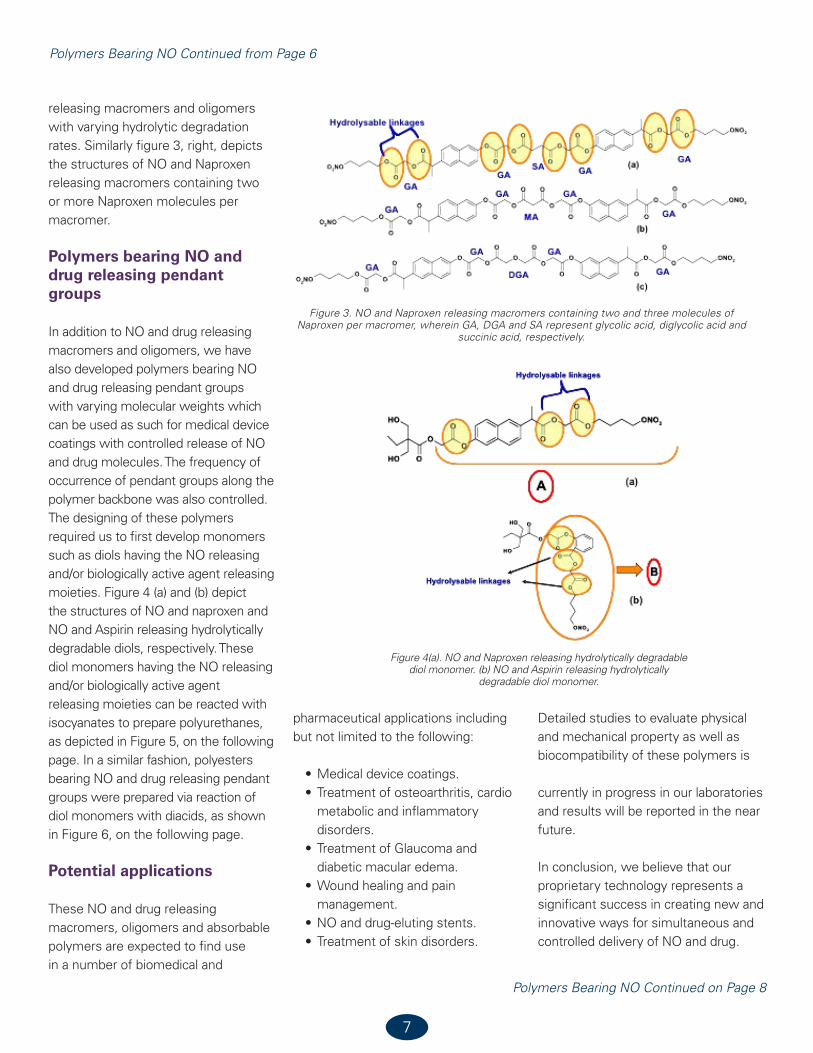
releasing macromers and oligomers with varying hydrolytic degradation rates. Similarly figure 3, right, depicts the structures of NO and Naproxen releasing macromers containing two or more Naproxen molecules per macromer.
Polymers bearing NO and drug releasing pendant groups
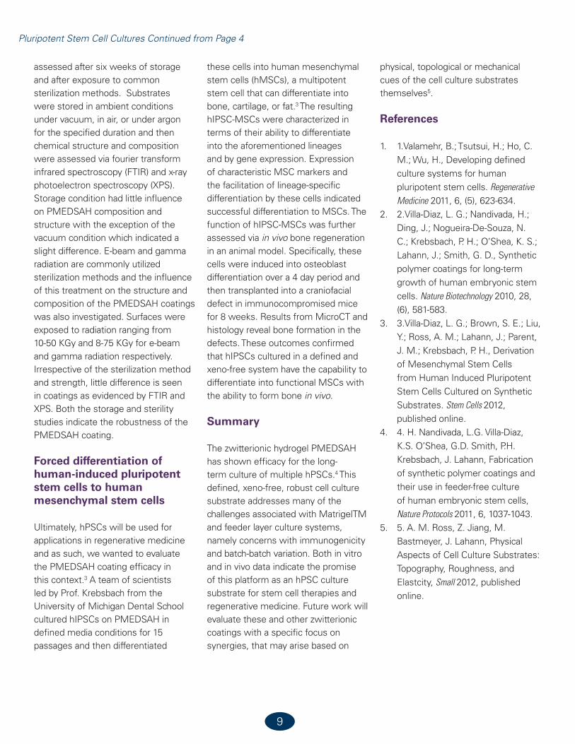
In addition to NO and drug releasing macromers and oligomers, we have also developed polymers bearing NO and drug releasing pendant groups with varying molecular weights which can be used as such for medical device coatings with controlled release of NO and drug molecules. The frequency of occurrence of pendant groups along the polymer backbone was also controlled. The designing of these polymers required us to first develop monomers such as diols having the NO releasing and/or biologically active agent releasing moieties. Figure 4 (a) and (b) depict the structures of NO and naproxen and NO and Aspirin releasing hydrolytically degradable diols, respectively. These diol monomers having the NO releasing and/or biologically active agent releasing moieties can be reacted with isocyanates to prepare polyurethanes, as depicted in Figure 5, on the following page. In a similar fashion, polyesters bearing NO and drug releasing pendant groups were prepared via reaction of diol monomers with diacids, as shown in Figure 6, on the following page.
Potential applications
These NO and drug releasing macromers, oligomers and absorbable polymers are expected to find use in a number of biomedical and
pharmaceutical applications including but not limited to the following:
•Medical device coatings.•Treatment of osteoarthritis, cardio
metabolic and inflammatory disorders.
•Treatment of Glaucoma and diabetic macular edema.
•Wound healing and pain management.
•NO and drug-eluting stents.•Treatment of skin disorders.
Detailed studies to evaluate physical and mechanical property as well as biocompatibility of these polymers is
currently in progress in our laboratories and results will be reported in the near future.
In conclusion, we believe that our proprietary technology represents a significant success in creating new and innovative ways for simultaneous and controlled delivery of NO and drug.
Polymers Bearing NO Continued from Page 6
Figure 3. NO and Naproxen releasing macromers containing two and three molecules of Naproxen per macromer, wherein GA, DGA and SA represent glycolic acid, diglycolic acid and
succinic acid, respectively.
Figure 4(a). NO and Naproxen releasing hydrolytically degradable diol monomer. (b) NO and Aspirin releasing hydrolytically
degradable diol monomer.
Polymers Bearing NO Continued on Page 8

Polymers Bearing NO Continued from Page 7
8
References
1. Bezwada, Rao S. Controlled release of nitric oxide and drugs from functionalized macromers and oligomers, US Patent 8,062,653.2. Bezwada, Rao S. Controlled release of nitric oxide and drugs from functionalized macromers and oligomers EP, 2398761A2.3. Bezwada, Rao S. Nitric Oxide and Drug Releasing Hydrolysable Macromers, Oligomers and Polymers, ACS Symposium Series 1054, Biomaterials,
Chapter 11, 197-220
Figure 5. Polyurethanes bearing NO and drug releasing pendant groups. Figure 6 Polyesters bearing NO and drug releasing pendant groups.
9
Pluripotent Stem Cell Cultures Continued from Page 4
assessed after six weeks of storage and after exposure to common sterilization methods. Substrates were stored in ambient conditions under vacuum, in air, or under argon for the specified duration and then chemical structure and composition were assessed via fourier transform infrared spectroscopy (FTIR) and x-ray photoelectron spectroscopy (XPS). Storage condition had little influence on PMEDSAH composition and structure with the exception of the vacuum condition which indicated a slight difference. E-beam and gamma radiation are commonly utilized sterilization methods and the influence of this treatment on the structure and composition of the PMEDSAH coatings was also investigated. Surfaces were exposed to radiation ranging from 10-50 KGy and 8-75 KGy for e-beam and gamma radiation respectively. Irrespective of the sterilization method and strength, little difference is seen in coatings as evidenced by FTIR and XPS. Both the storage and sterility studies indicate the robustness of the PMEDSAH coating.
Forced differentiation of human-induced pluripotent stem cells to human mesenchymal stem cells
Ultimately, hPSCs will be used for applications in regenerative medicine and as such, we wanted to evaluate the PMEDSAH coating efficacy in this context.3 A team of scientists led by Prof. Krebsbach from the University of Michigan Dental School cultured hIPSCs on PMEDSAH in defined media conditions for 15 passages and then differentiated
these cells into human mesenchymal stem cells (hMSCs), a multipotent stem cell that can differentiate into bone, cartilage, or fat.3 The resulting hIPSC-MSCs were characterized in terms of their ability to differentiate into the aforementioned lineages and by gene expression. Expression of characteristic MSC markers and the facilitation of lineage-specific differentiation by these cells indicated successful differentiation to MSCs. The function of hIPSC-MSCs was further assessed via in vivo bone regeneration in an animal model. Specifically, these cells were induced into osteoblast differentiation over a 4 day period and then transplanted into a craniofacial defect in immunocompromised mice for 8 weeks. Results from MicroCT and histology reveal bone formation in the defects. These outcomes confirmed that hIPSCs cultured in a defined and xeno-free system have the capability to differentiate into functional MSCs with the ability to form bone in vivo.
Summary
The zwitterionic hydrogel PMEDSAH has shown efficacy for the long-term culture of multiple hPSCs.4 This defined, xeno-free, robust cell culture substrate addresses many of the challenges associated with MatrigelTM and feeder layer culture systems, namely concerns with immunogenicity and batch-batch variation. Both in vitro and in vivo data indicate the promise of this platform as an hPSC culture substrate for stem cell therapies and regenerative medicine. Future work will evaluate these and other zwitterionic coatings with a specific focus on synergies, that may arise based on
physical, topological or mechanical cues of the cell culture substrates themselves5.
References
1. 1.Valamehr, B.; Tsutsui, H.; Ho, C. M.; Wu, H., Developing defined culture systems for human pluripotent stem cells. Regenerative Medicine 2011, 6, (5), 623-634.
2. 2.Villa-Diaz, L. G.; Nandivada, H.; Ding, J.; Nogueira-De-Souza, N. C.; Krebsbach, P. H.; O’Shea, K. S.; Lahann, J.; Smith, G. D., Synthetic polymer coatings for long-term growth of human embryonic stem cells. Nature Biotechnology 2010, 28, (6), 581-583.
3. 3.Villa-Diaz, L. G.; Brown, S. E.; Liu, Y.; Ross, A. M.; Lahann, J.; Parent, J. M.; Krebsbach, P. H., Derivation of Mesenchymal Stem Cells from Human Induced Pluripotent Stem Cells Cultured on Synthetic Substrates. Stem Cells 2012, published online.
4. 4. H. Nandivada, L.G. Villa-Diaz, K.S. O’Shea, G.D. Smith, P.H. Krebsbach, J. Lahann, Fabrication of synthetic polymer coatings and their use in feeder-free culture of human embryonic stem cells, Nature Protocols 2011, 6, 1037-1043.
5. 5. A. M. Ross, Z. Jiang, M. Bastmeyer, J. Lahann, Physical Aspects of Cell Culture Substrates: Topography, Roughness, and Elastcity, Small 2012, published online.

10
Post-Grant Proceedings
In the last issue of SurFacts, I discussed the changes in patent law inaugurated by the America Invents Act (AIA). In this article, I would like to focus specifically on the provisions for post-grant challenge to patents. While the previous patent laws allowed some challenges to issued patents, the new options have been greatly expanded. However, each of the different post-grant challenges has risks and benefits both for the patent owner and the challenger. The risk/benefit ratio will need to be strategically assessed by the requestor when determining how to challenge the issued patent.
Ex Parte Reexamination is an existing procedure allowing a third party to anonymously challenge a patent based only on prior art patents and printed publications. The challenger has the right to respond only to the patent owner’s statement in response to the USPTO’s initial decision to grant the request under a standard of presenting a substantial new question of patentability (SNQ). After that, the requestor plays no further role in the proceedings. The reexamination resembles a regular patent prosecution with the exception that the examination is carried out by the USPTO’s Central Re-Examination Unit (CRU), an elite unit of the examining corps. Reexamination proceeds by the new examiner issuing a new set of Office Actions which the patent owner then responds to following conventional patent prosecution.
Conclusion of the Reexam can result in confirmation of the claims as originally allowed, amendment of the claims, or cancellation of the claims. It is important to note that while some claims may be cancelled or amended, other claims may emerge unscathed, and the challenger is barred (estopped) from challenging the decision of the CRU in the courts.
Inter Partes Reexamination is an existing procedure that allows the patent challenger to participate in the reexamination. As with ex parte reexam, inter parte reexam takes place in the CRU. The standard for granting the request is a “Reasonable likelihood that the requester will prevail with respect to at least one of the claims challenged in the request” prior art considered is also limited to patents and printed publications. However, unlike ex parte review, in inter parte reexam the identity of the requestor is known and the requestor is allowed to respond to the patentee’s response to the CRU’s Office Actions. Theoretically, inter partes reexam can be initiated for patents granted after November 29, 1999, however, under the AIA, inter partes reexam will no longer be available after September 16, 2012.
Post-Grant Review is a new procedure that allows a third party to request review of the patent based on any ground of invalidity that could be raised in district court, including lack of written description,
non-enablement, or patent-ineligible subject matter in addition to prior art, printed publications, and patents within nine months of patent grant. The standard for granting the review is “the likelihood that at least one claim will be found unpatentable.” This procedure will allow for the participation of the requesting party and will be conducted before a new Patent Trial and Appeal Board (PTAB), not the CRU. Because the members of the PTAB are administrative patent judges, the proceeding held before it will be quasi-judicial in nature and will follow a judicial “pleading” format. The AIA requires that the post-grant review be concluded within one year from institution with one six-month extension available. As with inter partes reexam, the requestor will be stopped from pursuing further action in the USPTO, court or International Trade Commission (ITC) if an undesirable conclusion is reached.
Inter Partes Review is a new proceeding that can only be requested after the nine-month period of post-grant review has expired (unless the post-grant review is pending). Inter partes review is carried out before the PTAB in a pleading and response fashion and considers only patents and printed publications. The standard for granting the request is “a reasonable likelihood of prevailing on one of the challenged claims.” As with post-grant review, estoppels apply to the requestor after conclusion of the
By Colin Fairman, JD, PhD, Intellectual Property and Legal Editor
Post-Grant Proceedings Continued on Page 11
Join the Foundation that connects the academic, industrial, and regulatory committees within the surface science/biomedical communities!
Benefits of Membership:
•DiscountedregistrationatBioInterface,theannual symposium of the Surfaces in Bioma-terials Foundation.
•YourlogoandalinktoyourWebsiteinthemember directory on the official Web site of the Foundation, www.surfaces.org.
•ComplimentaryfullpageadinSurFACTS,theFoundation’s newsletter and discounts on all advertising.
Visit the Foundation at www.surfaces.org for a membership application or call 651-290-6267.
Wanted: MembersTo be leaders in the surface science community
•Joinaforumthatfostersdiscussionandsharingof surface and interfacial information•Haveyourvoiceheardandyourinterests represented within the surface science and biomedical community•Help shape workshops and symposia that further the world-wide education of surface sci-
ence•Promoteunderstandingofinterfacial issues common to researchers, bio-medical engineers and material
scientists.

12
reexamination regarding appeal to the USPTO, courts or the ITC with respect to any grounds that was or could have been raised during reexamination.
Supplemental Examination is a new proceeding that allows patent owners (but not practitioners) to “cure” inequitable conduct by submitting information relevant to the patent grant concealed from the Patent Office during prosecution. Supplemental Examination can only be initiated by the owner of a patent and will cost about $22,000. Supplemental Examination is not limited to patents and printed publications. In addition, while supplemental examination can be used by the patent owner to bring previously uncited art to the Office’s attention and thereby outflank a reexamination request by a potential infringer, if the Office determines that the newly cited art raises a substantial new question of patentability, the Office may, of its own accord, institute reexamination proceedings against the patent.
With regard to the above post-grant examination procedures, the potential instigator has various strategic implications to consider before commencing any action. These can be summed up:
Cost: it should be appreciated that any patent challenge in the patent office will generally be considerably less expensive than challenging a patent through the court system. In our experience, an ex parte reexam will cost the requestor approximately $20,000 to $30,000 to prepare and the patent owner approximately $50,000 to $60,000 to defend. An inter parte reexam generally costs
both parties about the same, in the range of approximately $100,000. In contrast, a fully blown patent litigation in the courts can be expected to cost both parties from about $500,000 to $1,000,000.
With respect to the new procedures of Post-grant review and inter partes review – because they will not come into effect until September 16, 2012—the actual costs for the actions can only be estimated. However, it should be appreciated that because the procedures will allow for the participation of both the requestor party and the patent owner in a pleadings-type format, the cost of these proceedings will be very similar to an inter partes reexamination, e.g., approximately $100,000.
Ability to amend claims: in a judicial proceeding, claims that are found to be unpatentable, due to not only anticipation or obviousness over any prior art but also for lack of enablement or written description, will be cancelled. While a court may find that some claims survive the challenge, there is no ability to amend the claims to overcome the prior art or other deficiencies. In contrast, in proceedings taking place in the patent office, claims may be amended to overcome the prior art. Therefore, there is a chance that the claims may be narrowed during the administrative proceedings resulting in the maintenance of claims that were not present in the originally challenged patent.
Presumption of validity: a patent issued by the USPTO has the presumption of validity. Consequently,
in a judicial proceeding the standard of review is “clear and convincing evidence of invalidity”. However, in post-issuance proceedings taking place within the patent office, there is no presumption of validity. Therefore, the standard used by the patent office is a preponderance of evidence. The difference in review standard may be significant, especially when a case is litigated before a jury and the technology may be sophisticated.
Prosecution history estoppel: prosecution history estoppels is a term of art used to refer to statements made by the patent owner during prosecution to overcome rejections made over the prior art. Thus, for example, if the office cites prior art that teaches a surface coating that comprises a cross-linked polymer of greater than 20 carbon atoms, the applicant may note to the examiner that the cross-linked polymer used has only up to 15 carbons. However, while technology may develop new methods of providing cross-linked polymers according to the claims with greater than 15 carbons, the statements made by the applicant in order to gain allowance will limit the scope of the claims to up to 15 carbon atoms, regardless of the actual language of the issued claims. Similarly, in a post-issuance proceeding within the patent office, while claims may survive, the patent owner may make narrowing statements in arguments used to overcome the art cited by the challenger.
Judicial estoppel: as discussed above, judicial estoppel is a statutory limitation against pursuing further challenges to the patent once a review has been pursued in the patent office. Thus, an
Post-Grant Proceedings Continued from Page 9
Post-Grant Proceedings Continued on Page 13

13
undesirable outcome for the requesting party cannot be further pursued in the courts. In addition, the effect of a post-issuance proceeding resulting in claims that survive the review will result in claims that may be deemed by other challengers as “bullet proof”. While there is no restraint on others serially challenging a patent in the patent office or in court, the confirmation of claims in a post-issuance proceeding will no doubt influence the outcome of any other such challenges by different parties.
In addition, in the event where estoppel does not attach, such as ex parte reexam, there will be a heightened perception of validity in any following judicial proceeding if only because the court and/or jury will be made aware that the patent has been further scrutinized by the elite CRU.
Finally, in those cases where claims do survive the reexamination/review process, amendment of the claims in any way will result in intervening rights, a concept whereby the challenger or infringer is accorded rights that would
otherwise infringe the patent claims. This may happen when a claim is amended or a new claim allowed. In such cases, a broader claim may be amended to overcome the prior art and, while the infringing act may be encompassed by both the original claim and the amended claim, the original claim is cancelled and the amended claim is deemed to be in effect only since confirmed by the post-issuance proceeding.
2012 NESAC/BIO WORKSHOP
August 13 - 15, 2012
National ESCA and Surface Analysis Center for Biomedical Problems
University of Washington, Seattle, Washington USA
Learn to Characterize Biomaterial Surface Composition and Structure
The National ESCA and Surface Analysis Center for Biomedical Problems (NESAC/BIO) is a state-of-the-art surface analysis center whose mission is the development and application of surface analysis methods for biomedical research.
This NESAC/BIO Surface Characterization Workshop includes lectures and surface analysis demonstrations. Demonstrations on NESAC/BIO instruments will provide application examples for the material covered in the workshop lectures. Attendees will learn the capabilities of surface analysis methods and how to intelligently review data received from surface analysis laboratories. The workshop will focus on the following methods:
•Electron Spectroscopy for Chemical Analysis (ESCA) •Secondary Ion Mass Spectrometry (SIMS)•Scanning Probe Microscopy (SPM) •Sum Frequency Generation (SFG)•Near Edge Xray Absorption Fine Structure (NEXAFS)•Multivariate Data Analysis•Contact Angle Measurements •Surface Modification •Surface Plasmon Resonance
NESAC/BIO is funded by NIBIB , NIH , Grant # EB002027For More Information:
http://www.nb.uw.edu/home/workshop/
Surface Characterization of Biomaterials

14
FDA Issues Final Guidance on Benefit-Risk Determinations
On March 28 the FDA issued the final version of its Guidance, “Factors to Consider when Making Benefit-Risk Determinations in Medical Device Premarket Approval and De Novo Classifications.” Part of its transparency initiative, the guidance is unique in its intent to explain the factors that FDA considers when making benefit-risk determinations in its premarket review of devices subject to PMAs or addressed in de novo petitions. The Guidance applies to both diagnostic devices (regulated by OIVD) and therapeutic devices (regulated by CDRH). The FDA’s press release announcing the availability of the document with some commentary by Jeffrey Shuren provides a succinct summary of the guidance document.
Several points made in the guidance are worthy of note. The first is that the FDA provides its rationale for requiring more substantive evidence of safety and efficacy for iterations of devices with the same intended use:
“… because the weighting of the factors for a type of device may change over time – such as a device no longer being a first-of-a-kind or the only available treatment as new therapies are approved – the benefit-risk determination for a specific device at one point in time may no longer represent the proper weighting of the factors for the same or similar type of device in the future.”
Many of my clients have complained that they are required to submit more information to support safety
and efficacy than manufacturers of devices already marketed for the same intended purposes and this statement, along with the one quoted below, provides the FDA’s rationale for “ratcheting up” requirements for device iterations.
“It is not unusual for novel devices that address an unmet medical need to have relatively small probable benefits, and FDA may determine the novel device to be reasonably safe and effective even though the applicant demonstrates a relatively small probable benefit. In addition, the development of innovative technology may provide additional future benefits to patients. With subsequent iterations of the device its benefit-risk profile may change (e.g., the benefits may increase or the risks may be reduced), the expected level of safety and effectiveness may change, and later versions may offer significant advantages over the initial device. In these circumstances, in order to facilitate patient access to new devices important for public health and to encourage innovation, we may tolerate greater uncertainty in an assessment of benefit or risk than for most established technologies, particularly when providers and patients have limited alternatives available.”
Also noteworthy is that the FDA considers “Patient tolerance for risk and perspective on benefit” in its assessment of the probable benefits and risks of devices:
“…if the risks are identifiable and definable, risk tolerance will vary among patients, and this will affect individual patient decisions as to whether the risks are acceptable15 § (d) (1) in exchange for a probable benefit. When making a benefit-risk determination at the time of approval or de novo classification, FDA recognizes that patient tolerance for risk and a patient-centric assessment of risk may reveal reasonable patients who are willing to tolerate a very high level of risk to achieve a probable benefit, especially if that benefit results in an improvement in quality of life. How data concerning patient risk tolerance and other patient-centered metrics are developed will vary depending on a number of factors, including the nature of the disease or condition and the availability of existing treatments, as well as the risks and benefits they present. FDA encourages any sponsor that is considering developing such data to have early interaction with the appropriate FDA review division.”
I have never attempted to include, in a submission to the FDA, an assessment of a patient’s perceived benefits and risks associated with a new device. Collection of data on patient-centric metrics may prove to be challenging, but certainly is worthwhile if the data can be used to support and foster the introduction of truly novel and innovative devices to the marketplace.
The guidance includes a “Worksheet for Benefit-Risk Determinations” as
By Phil Triolo, SurFACTS Regulatory Editor
FDA Guidance Continued on Page 18
15
Electron Microscopy of Biomaterials-Tissue Interfaces
The transmission electron microscope (TEM) is a powerful tool for imaging and analysing the structure and chemistry of biomaterials interfaces with high energy and spatial resolution. This technique can provide detailed information about fundamental processes occurring at these interfaces. This analysis can provide insight into mechanisms of bioactivity or implant failure, how the toxicology of nanoparticles relates to their physicochemical properties or about tissue pathologies, such as osteogenesis imperfecta or neurodegenerative diseases. However, imaging and analysis of biomaterials-tissue interfaces can be challenging. This article will discuss the challenges involved with characterising biological materials in the TEM, how these problems can be overcome and potential applications of correlative microscopy methods for analysing the failure and biocompatibility of biomedical materials.
The challenge in imaging biomaterials-tissue interfaces is to probe accurately, with sufficient resolution, the chemistry and structure of the inorganic and organic phases simultaneously. The integrity of the organic phase and the interface must also be preserved and adequate contrast must be achieved between the individual components. Whilst heavy metal staining is an option to improve contrast from the organic phase, the stains can modify the chemistry of the sample, making
it unsuitable for chemical analysis. A further challenge is that the electron beam can damage the sample, altering the structure and changing the local chemistry (e.g. destroying the crystallinity of the mineral phase in tissues). 3-D imaging and analysis are frequently required to accurately reconstruct the morphology and chemistry across heterogeneous interfaces or complex 3-D architectures found in biological systems; this information is lost in 2-D projection images. In biomaterials and biological systems, it is also crucial to preserve the chemistry of the bio- or nano-material as any slight modification in their chemistry or oxidation state caused during processing for TEM analysis (e.g. fixation and staining) could make the results ambiguous and liable to misinterpretation. For example, in nanotoxicology the inflammatory response of cells to nanomaterials is critically dependent on their physicochemical properties (i.e. chemistry, oxidation state or functionalisation), therefore it is vital to preserve their chemistry during both TEM processing and analysis, or predictions about their potential safety may be unreliable. This review aims to discuss the development and application of analytical and 3-D microscopy techniques to analyse a range of bio/nano materials interfaces at medium to high spatial resolution from ~1µm to 1 nm using a range of techniques, namely dual beam focussed ion beam milling,
energy filtered TEM (EFTEM), high-angle annular dark-field scanning transmission electron microscopy (HAADF-STEM) and electron tomography.
In this review we will explain the techniques available in the analytical electron microscope and discuss case studies in which electrons have been employed to gain understanding of a biological system at the nanoscale. This is not in any way a comprehensive list, but an illustration of the potential benefits:
Analytical and 3-D transmission electron microscopy techniques
Scanning transmission electron microscopy (STEM): STEM can use a high angle annular dark field (HAADF) detector, which collects electrons that undergo Rutherford scattering which are scattered elastically to high angles. The intensity of the signal in the resulting images is approximately proportional to the square of the atomic number of the scattering atoms Z2.
Electron energy loss spectroscopy (EELS): EELS can selectively map the distribution of nanomaterials inside cells and tissues at ultra high spatial and energy resolution. EELS is a technique where high energy electrons incident on a sample scatter from, and therefore lose energy to, atoms in the sample. The energy lost in a particular
By Alexandra Porter, Dept. Materials, Imperial College London
Electron Microscopy Continued on Page 16

Electron Microscopy Continued from Page 15
16Electron Microscopy Continued on Page 17
scattering event is lost to an atom’s electrons and only takes discrete values (quanta) which are different for every element. The electrons are transmitted through a sample and then the energy that they lose is recorded in the form of a loss spectrum. The spectrum of each element is comprised of peaks or edges positioned at characteristic energy-losses. The shape and position of each edge also provides us with information about the bonding environment of the sample being analysed. Therefore, EELS spectra provide detailed information about the elemental composition and bonding state within a sample at a very high spatial resolution.
Energy-filtered TEM (EFTEM): EFTEM also maps the composition of the sample. EFTEM is a technique based on EELS which records images taken at different energies. The basis of this technique is that an energy-
filter slit is used which only allows electrons through which have lost certain energies. By selecting different energies, elemental EFTEM maps can be produced. This technique does not have the energy resolution of EELS, however larger areas can be mapped relatively easily.
Electron tomography is a technique for obtaining a three-dimensional image from a TEM specimen. Data collection for electron tomography involves collecting a series of images while tilting the specimen around a single axis at regular intervals. A three-dimensional structure can then be re-constructed using the series of images collected to give high-resolution information about the material being analyzed.
Dual beam focussed ion beam (DB-FIB) instrument: DB-FIB technique (Figure 1) uses the combination of an
ion beam to mill, and subsequently reveal the internal surfaces of the sample, and an electron beam to record successive image slices. By progressively milling through the sample and recording images, an entire 3-D volume of the cell can then be reconstructed from the serial images to give 3-D information about the sample. Milling can be performed with a precision of ~10 nm depth and up to 100 µm width allowing
for analysis, in three dimensions, of the structure of materials from 0.1mm to <100 nm. Approximately 500 serial images from a sample can be generated automatically overnight; therefore both quantitative and qualitative information can be acquired. Example systems which benefit from this approach
Nanotoxicology. There are increasing concerns that engineered nanomaterials (ENMs) will result in adverse effects in biological systems. However, most of the published research, although leading to prediction of a wide range of health effects, does not provide detailed physicochemical characterization of the ENMs; and more data are needed on the ENM physicochemical properties that are critical to the biological effects. For example, little is known about the effect of changes in ENM physicochemical properties (e.g., agglomeration, aggregation, dissolution, oxidation state) upon the interaction with a biological system on the absorption, translocation, and the resulting pathophysiological events. The lack of detailed mechanistic information relating the physicochemical properties of ENMs to their reactivity with the tissues has arisen due to the lack of an imaging methodology to probe whether they damage the cell or tissue structure, which cells or tissues the ENMs target, their subsequent interaction inside cells and whether they are transformed in the extracellular matrix or by the action of the cell. Acquisition of this information requires a multi-scale correlative microscopy
Figure 1 Serial images, a-d through a human monocyte cell exposed to MWNTs. The cells have been bulk stained with osmium tetroxide. Images
taken with a dual beam FIB-SEM in backscattered electron mode.
17 Contact Angles Continued on Page 16
Electron Microscopy Continued from Page 16
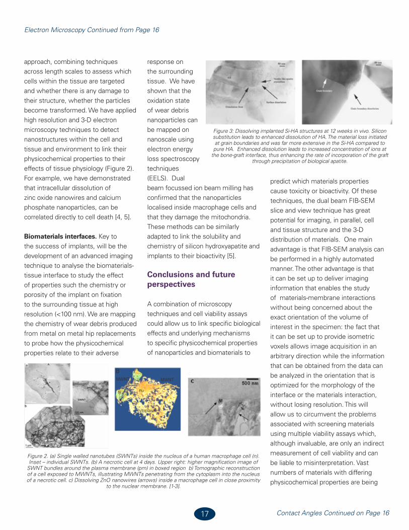
approach, combining techniques across length scales to assess which cells within the tissue are targeted and whether there is any damage to their structure, whether the particles become transformed. We have applied high resolution and 3-D electron microscopy techniques to detect nanostructures within the cell and tissue and environment to link their physicochemical properties to their effects of tissue physiology (Figure 2). For example, we have demonstrated that intracellular dissolution of zinc oxide nanowires and calcium phosphate nanoparticles, can be correlated directly to cell death [4, 5].
Biomaterials interfaces. Key to the success of implants, will be the development of an advanced imaging technique to analyse the biomaterials-tissue interface to study the effect of properties such the chemistry or porosity of the implant on fixation to the surrounding tissue at high resolution (<100 nm). We are mapping the chemistry of wear debris produced from metal on metal hip replacements to probe how the physicochemical properties relate to their adverse
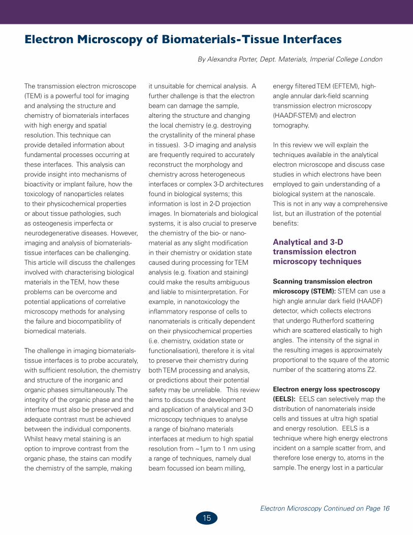
response on the surrounding tissue. We have shown that the oxidation state of wear debris nanoparticles can be mapped on nanoscale using electron energy loss spectroscopy techniques (EELS). Dual beam focussed ion beam milling has confirmed that the nanoparticles localised inside macrophage cells and that they damage the mitochondria. These methods can be similarly adapted to link the solubility and chemistry of silicon hydroxyapatite and implants to their bioactivity [5].
Conclusions and future perspectives
A combination of microscopy techniques and cell viability assays could allow us to link specific biological effects and underlying mechanisms to specific physicochemical properties of nanoparticles and biomaterials to
predict which materials properties cause toxicity or bioactivity. Of these techniques, the dual beam FIB-SEM slice and view technique has great potential for imaging, in parallel, cell and tissue structure and the 3-D distribution of materials. One main advantage is that FIB-SEM analysis can be performed in a highly automated manner. The other advantage is that it can be set up to deliver imaging information that enables the study of materials-membrane interactions without being concerned about the exact orientation of the volume of interest in the specimen: the fact that it can be set up to provide isometric voxels allows image acquisition in an arbitrary direction while the information that can be obtained from the data can be analyzed in the orientation that is optimized for the morphology of the interface or the materials interaction, without losing resolution. This will allow us to circumvent the problems associated with screening materials using multiple viability assays which, although invaluable, are only an indirect measurement of cell viability and can be liable to misinterpretation. Vast numbers of materials with differing physicochemical properties are being
Figure 2. (a) Single walled nanotubes (SWNTs) inside the nucleus of a human macrophage cell (n). Inset – individual SWNTs. (b) A necrotic cell at 4 days. Upper right: higher magnification image of
SWNT bundles around the plasma membrane (pm) in boxed region b) Tomographic reconstruction of a cell exposed to MWNTs, illustrating MWNTs penetrating from the cytoplasm into the nucleus of a necrotic cell. c) Dissolving ZnO nanowires (arrows) inside a macrophage cell in close proximity
to the nuclear membrane. [1-3].
Figure 3: Dissolving implanted Si-HA structures at 12 weeks in vivo. Silicon substitution leads to enhanced dissolution of HA. The material loss initiated at grain boundaries and was far more extensive in the Si-HA compared to pure HA. Enhanced dissolution leads to increased concentration of ions at
the bone-graft interface, thus enhancing the rate of incorporation of the graft through precipitation of biological apatite.

18
FDA Guidance Continued from Page 14 Electron Microscopy Continued from Page 17
produced commercially and it is not feasible to test each and every material currently used in consumer products, to monitor their cytotoxicity. An integrated approach combining imaging and cell viability assays will allowing identifing features of interest, and to then capture high-resolution snapshots to link the structure and chemistry of the materials, and how this evolves with time, to cell or tissue function. This approach will allow us to link the physicochemical properties of materials directly to their effect on cell or tissue structure or metabolism. We suggest that
these methods will be invaluable to assess which properties of nanomaterials cause toxicity to predict a safety-window for their commercial use.
References1. Porter, A.E. et al. Nat Nanotechnol.
(2007) 2:713-7.2. Cheng C et al., Biomaterials. 30
(2009) (25):4152-60.3. Muller KH et al. ACS Nano. 23
(2010) 4(11):6767-79.4. Motskin M et al. Biomaterials
(2009) 30(19):3307-17.5. Porter AE et al. Biomaterials 25
(2004) (16), pp. 3303–3314.6. Acknowledgement: An ERC
starting grant for Dr. A Porter.
Appendix B, and hypothetical examples of these Worksheets in Appendix C. These provide very worthwhile insights into the FDA’s assessments.
A full analysis of the document’s contents could require several pages of commentary. I suggest that you read it through several times, and use it as a reference when framing arguments to support risk/benefit assessments for risk management purposes, as well as to substantiate safety and efficacy in 510(k)s, PMAs and de novo petitions.
BioInterface 2012 is focused at providing a venue where the most recent innovations and ideas can be presented and discussed. Among the broad range of topics covered by the conference are biomaterials, surface modification of devices, wound healing, drug delivery, regulatory issues, etc.
The conference has a strong applied focus and brings together representatives from industrial, academic, clinical and regulatory communities. Student participation is actively encouraged at the BioInterface conference, with a student poster competition and a student meeting where students can interact with industry representatives. There is a prestigious annual award, the Excellence in Surface Science Award, and the conference attracts noteworthy speakers from around the globe.
Register for BioInterface 2012 today at www.biointerface2012ireland.com.
Registration for biointerface 2012 is now open!
INTERFACE2012BIO

19
Thank You to Our Members!
Nano Surface Technologies
A S U B S I D I A R Y O F W . L . G O R E & A S S O C I A T E S
Surface SolutionsLaboratories Incorporated
Surface SolutionsLaboratories Incorporated
MARK 1
MARK 2