Embed Size (px)
Citation preview

Instruction Manual
Supplement for High-Capacity Inverters
Designed for Fan and Pump Applications
200 V class series 90 kW: FRN90F1S-2 110 kW: FRN110F1S-2 400 V class series 280 kW: FRN280F1S-4
to 560 kW: FRN560F1S-4
Thank you for purchasing our FRENIC-Eco series of inverters. • This product is designed to drive a three-phase induction motor. Read through this supplement in
conjunction with the instruction manual (INR-SI47-1059-E) and be familiar with the handling procedure for correct use.
• Improper handling might result in incorrect operation, a short life, or even a failure of this product as well as the motor.
• Deliver this supplement to the end user of this product. Keep this supplement in a safe place until this product is discarded.
• For how to use an optional device, refer to the installation and instruction manuals for that optional device.
Fuji Electric Systems Co., Ltd. INR-HF52250b-E

Copyright © 2006-2009 Fuji Electric Systems Co., Ltd. All rights reserved. No part of this publication may be reproduced or copied without prior written permission from Fuji Electric Systems Co., Ltd.
All products and company names mentioned in this manual are trademarks or registered trademarks of their respective holders.
The information contained herein is subject to change without prior notice for improvement.
i
Preface This manual, a supplement to the FRENIC-Eco Instruction Manual (INR-SI47-1059 -E), contains pages that apply exclusively to high-capacity inverters. Substitute them for the corresponding pages in the original manual. Chapters 2 and 10, however, are complete in themselves, so there is no need to refer back.
Safety precautions Read this manual thoroughly before proceeding with installation, connections (wiring), operation, or maintenance and inspection. Ensure you have sound knowledge of the device and familiarize yourself with all safety informa-tion and precautions before proceeding to operate the inverter. Safety precautions are classified into the following two categories in this manual.
Failure to heed the information indicated by this symbol may lead to dangerous conditions, possibly resulting in death or serious bodily injuries.
Failure to heed the information indicated by this symbol may lead to dangerous conditions, possibly resulting in minor or light bodily injuries and/or substantial property damage.
Failure to heed the information contained under the CAUTION title can also result in serious consequences. These safety precautions are of utmost importance and must be observed at all times.
How this manual is organized This manual is made up of the following chapters.
Chapter 2 MOUNTING AND WIRING OF THE INVERTER This chapter provides operating environment, precautions for installing the inverter, wiring instructions for the motor and inverter.
Chapter 3 OPERATION USING THE KEYPAD This chapter describes inverter operation using the keypad. The inverter features three operation modes (Running, Programming and Alarm modes) which enable you to run and stop the motor, monitor running status, set function code data, display running information required for maintenance, and display alarm data.
Chapter 5 FUNCTION CODES This chapter provides a list of the function codes. Function codes to be used often and irregular ones are de-scribed individually.
Chapter 7 MAINTENANCE AND INSPECTION This chapter describes inspection, measurement and insulation test which are required for safe inverter operation. It also provides information about periodical replacement parts and guarantee of the product.
Chapter 8 SPECIFICATIONS This chapter lists specifications including output ratings, control system, external dimensions and protective functions.
Chapter 10 CONFORMITY WITH STANDARDS This chapter describes standards with which the FRENIC-Eco series of inverters comply.
Icons The following icons are used throughout this manual.
This icon indicates information which, if not heeded, can result in the inverter not operating to full effi-ciency, as well as information concerning incorrect operations and settings which can result in accidents.
This icon indicates information that can prove handy when performing certain settings or operations.
This icon indicates a reference to more detailed information.

vi/vii
Conformity with Low Voltage Directive in the EU If installed according to the guidelines given below, inverters marked with CE can be considered to be compliant with the Low Voltage Directive 73/23/EEC.
1. Be sure to earth the grounding terminal zG. Use an earth wire sized more than that of the power wires used in the power dispatch system. Do not use a residual-current-operated protective device (RCD)* or an earth leakage circuit breaker (ELCB)* as a sole mechanism of electric shock protection.
*With overcurrent protection.
2. Use an MCCB, RCD/ELCB or MC in conformity with EN or IEC standards.
3. When an RCD/ELCB is used for protection of electric shock caused by a direct or indirect contact to the live parts, insert a type B RCD/ELCB in input lines (primary) of the inverter for the 3-phase 200 V or 400 V power source.
4. Use inverters in an environment that does not exceed pollution degree 2. If inverters are to be used in an environment with pollution degree 3 or 4, place them in an enclosure of IP54 or above.
5. To protect human body from an electric shock caused by a contact to live parts, install inverters, AC reactor and input /output filter in the enclosure of IP2X. In the case where human body easily contacts to live parts, a top panel of the enclosure should be IP4X or higher.
6. Do not directly connect a copper wire to the grounding terminal. Use a crimp terminal with tin or equivalent plating to connect the earth wire.
7. When using inverters at an altitude of more than 2000 m, note that the basic insulation applies to the insulation degree of the control circuitry. At an altitude of more than 3000 m, inverters cannot be used.
8. Use the wires listed in EN60204 Appendix C.
Note: A box ( ) in the above table replaces A, K, or E depending on the shipping destination.
*1 The frame size and model of the MCCB or RCD/ELCB (with overcurrent protection) will vary, depending on the power transformer capacity. Refer to the related technical documentation for details.
*2 The recommended wire size for main circuits is for the 70°C 600V PVC wires used at an ambient temperature of 40°C.
Recommended wire size (mm2)
Control circuit MCCB or
RCD/ELCB *1
Rated current (A)
Main power input *2
[L1/R, L2/S, L3/T]Inverter’s
grounding [zG]
Pow
er s
uppl
y vo
ltage
Nom
inal
app
lied
mot
or (k
W)
Inverter type
W/ DCR
W/o DCR
W/ DCR
W/o DCR In
verte
r out
puts
*2
[U, V
, W]
DC
reac
tor
[P1,
P(+
)]
Screwterminal
base
Europe type
terminal block A
ux. c
ontro
l pow
er
supp
ly [R
0, T
0]
Aux
. fan
pow
er
supp
ly [R
1, T
1]
90 FRN90F1S-2 400 185 240 120x2
Thre
e-ph
ase
200
V
110 FRN110F1S-2 500 150x2 300 150x2
280 FRN280F1S-4 600 185x2 185x2315 FRN315F1S-4 700
185x2240x2
355 FRN355F1S-4 800 240x2 150x3240x2
400 FRN400F1S-4 185x3 185x3 240x3450 FRN450F1S-4
1000 240x3
500 FRN500F1S-4 240x3 300x3
Thre
e-ph
ase
400
V
560 FRN560F1S-4 1200
--
300x3
--
300x3 300x4
0.25 to
0.75
0.25to
0.752.5 2.5

viii
Conformity with UL standards and CSA standards (cUL-listed for Canada) UL/cUL-listed inverters are subject to the regulations set forth by the UL standards and CSA standards (cUL-listed for Canada) by installation within precautions listed below.
1. Solid state motor overload protection (motor protection by electronic thermal overload relay) is provided in
each model. Adjust function codes F10 to F12 to decide the protection level.
2. Suitable for use on a circuit capable of delivering not more than 100,000 rms three-phase symmetrical amperes, 240 Volts maximum for 200V class input 30 kW or less, 230 Volts maximum for 200V class input 37 kW or above or 480 Volts maximum for 400V class input.
3. Use 75°C Cu wire only.
4. Use Class 1 wire only.
5. Field wiring connections must be made by a UL Listed and CSA Certified closed-loop terminal connector sized for the wire gauge involved. Connector must be fixed using the crimp tool specified by the connector manufacturer.
6. All circuits with terminals L1/R, L2/S, L3/T, R0, T0, R1, T1 must have a common disconnect and be connected to the same pole of the disconnect if the terminals are connected to the power supply.

ix
Conformity with UL standards and CSA standards (cUL-listed for Canada) (continued)
1. Required torque
Note: A box ( ) in the above table replaces A, K, or E depending on the shipping destination.
Note: The unit of values in parentheses ( ) is N•m.
Required torque Ib-in (N•m)
Control circuit
Pow
er s
uppl
y vo
ltage
Inverter type Main
terminal Ground Aux. control
power supply R0, T0 Screw terminal
base Europe type
terminal block
FRN90F1S-2
Thre
e-ph
ase
200
V
FRN110F1S-2
424.7 (48)
238.9 (27)
10.6 (1.2)
6.1 (0.7)
4.4 (0.5)
FRN280F1S-4
FRN315F1S-4
FRN355F1S-4
FRN400F1S-4
FRN450F1S-4
FRN500F1S-4
Thre
e-ph
ase
400
V
FRN560F1S-4
424.7 (48)
238.9 (27)
10.6 (1.2)
6.1 (0.7)
4.4 (0.5)

ix-1
Conformity with UL standards and CSA standards (cUL-listed for Canada) (continued)
2. Wire size
Note: A box ( ) in the above table replaces A, K, or E depending on the shipping destination.
Note: The unit of values in parentheses ( ) is mm2.
Wire size AWG (mm2)
Control circuit Main terminal Ground
Pow
er s
uppl
y vo
ltage
Inverter type
Wire size
Ring Terminal
JST Cat. No.
Wire size
Ring Terminal
JST Cat. No.
Aux. Control Power Supply R0, T0
Aux. Fan Power Supply R1, T1
Screw terminal
base
Europe type
terminal block
FRN90F1S-2 4/0X2 (107.2X2) R100-12
Thre
e-ph
ase
200
V
FRN110F1S-2 250X2 (127X2) R150-12
2 (33.6) R38-10 14
(2.1)14
(2.1) 20
(0.5) 20
(0.5)
FRN280F1S-4
FRN315F1S-4
400X2 (203X2) R200-12 1/0
(53.5) R60-10
FRN355F1S-4
FRN400F1S-4
350X3 (177X3) 180-12 2/0
(67.4) 70-10
FRN450F1S-4
FRN500F1S-4
Thre
e-ph
ase
400
V
FRN560F1S-4
400X4 (203X4) R200-12 3/0
(85X2) R80-10
14 (2.1)
14 (2.1)
20 (0.5)
20 (0.5)

xiv
Table of ContentsPreface ............................................................................i
Safety precautions..............................................................i How this manual is organized ................................................i Chapter 2 MOUNTING AND WIRING OF THE
INVERTER ..................................................... 2-1 2.1 Operating Environment ......................................... 2-1 2.2 Installing the Inverter ............................................. 2-1 2.3 Wiring.................................................................... 2-4
2.3.1 Removing and mounting the terminal block (TB) cover and the front cover............. 2-4
2.3.2 Terminal arrangement diagram and screw specifications ................................................ 2-6
2.3.3 Recommended wire sizes............................. 2-7 2.3.4 Wiring precautions ........................................ 2-8 2.3.5 Wiring for main circuit terminals and
grounding terminals ...................................... 2-8 2.3.6 Wiring for control circuit terminals............... 2-14 2.3.7 Setting up slide switches and handling
control circuit terminal symbol plate............ 2-23 2.4 Mounting and Connecting a Keypad ................... 2-25
2.4.1 Mounting style and parts needed for connection .................................................. 2-25
2.4.2 Mounting/installing steps............................. 2-26 2.5 Cautions Relating to Harmonic Component,
Noise, and Leakage Current ............................... 2-28 Chapter 3 OPERATION USING THE KEYPAD............. 3-25
3.4 Programming Mode............................................. 3-25 3.4.6 Reading maintenance information
– Menu #5 "Maintenance Information"........ 3-25 Chapter 5 FUNCTION CODES ....................................... 5-8 Chapter 7 MAINTENANCE AND INSPECTION .............. 7-3
7.3 List of Periodical Replacement Parts .................... 7-3 7.3.1 Judgment on service life ............................... 7-3
7.4 Measurement of Electrical Amounts in Main Circuit ....................................................... 7-5
Chapter 8 SPECIFICATIONS.......................................... 8-1
8.1 Standard Models ................................................... 8-1 8.1.1 Three-phase 200 V series ............................ 8-1 8.1.2 Three-phase 400 V series ............................ 8-2
8.4 Terminal Specifications.......................................... 8-8 8.4.1 Terminal functions......................................... 8-8 8.4.2 Running the inverter with keypad.................. 8-9
8.5 External Dimensions ........................................... 8-12 8.5.1 Standard models......................................... 8-12 8.5.2 DC reactor .................................................. 8-15
Chapter 10 CONFORMITY WITH STANDARDS ............ 10-1
10.1 Conformity with UL Standards and Canadian Standards (cUL-listed for Canada) ...................... 10-1
10.1.1 General....................................................... 10-1 10.1.2 Considerations when using FRENIC-Eco
as a product certified by UL or cUL............. 10-1 10.2 Conformity with EU Directives............................. 10-1
10.3 Conformity with Low Voltage Directive ................10-1 10.3.1 General .......................................................10-1 10.3.2 Considerations when using FRENIC-Eco
as a product in conformity with Low Voltage Directive ......................................................10-1
10.4 Conformity with the EMC Directive in the EU ......10-2 10.4.1 General .......................................................10-2 10.4.2 EMC-compliant filter (Option)......................10-2 10.4.3 Recommended installation of
EMC-compliant filter....................................10-3 10.4.4 EMC-compliant environment and class.......10-3

2-1
Chapter 2 MOUNTING AND WIRING OF THE INVERTER 2.1 Operating Environment
Install the inverter in an environment that satisfies the requirements listed in Table 2.1.
Table 2.1 Environmental Requirements
Item Specifications
Site location Indoors
Ambient temperature
-10 to +50°C
Relative humidity
5 to 95% (No condensation)
Atmosphere The inverter must not be exposed to dust, direct sunlight, corrosive gases, flammable gas, oil mist, vapor or water drops. Pollution degree 2 (IEC60664-1) (Note 1) The atmosphere can contain a small amount of salt. (0.01 mg/cm2 or less per year) The inverter must not be subjected to sudden changes in temperature that will cause condensation to form.
Altitude 1,000 m max. (Note 2)
Atmospheric pressure
86 to 106 kPa
3 mm (Max. amplitude) 2 to less than 9 Hz 2 m/s2 9 to less than 55 Hz
Vibration
1 m/s2 55 to less than 200 Hz
2.2 Installing the Inverter
(1) Mounting base The temperature of the heat sink will rise up to approx. 90°C during operation of the inverter, so the inverter should be mounted on a base made of material that can withstand temperatures of this level.
Install the inverter on a base constructed from metal or other non-flammable material. A fire may result with other material.
(2) Clearances Ensure that the minimum clearances indicated in Figure 2.1 are maintained at all times. When installing the inverter in the enclosureof your system, take extra care with ventilation inside the enclosure as the temperature around the inverter will tend to increase. Do not install the inverter in a small enclosure with poor ventilation.
When mounting two or more inverters Horizontal layout is recommended when two or more inverters are tobe installed in the same unit or enclosure. If it is necessary to mount the inverters vertically, install a partition plate or the like between theinverters so that any heat radiating from an inverter will not affect the one/s above.
Table 2.2 Output Current Derating Factor in Relation to Altitude
Altitude Output current derating factor
1000 m or lower 1.00
1000 to 1500 m 0.97
1500 to 2000 m 0.95
2000 to 2500 m 0.91
2500 to 3000 m 0.88
(Note 1) Do not install the inverter in anenvironment where it may be exposed tocotton waste or moist dust or dirt which willclog the heat sink in the inverter. If theinverter is to be used in such anenvironment, install it in the enclosure ofyour system or other dustproof containers.
(Note 2) If you use the inverter in analtitude above 1000 m, you should apply anoutput current derating factor as listed inTable 2.2.
Leave at least 100 mm of clearance also in front of the inverter. Figure 2.1 Mounting Direction and
Required Clearances
2-2
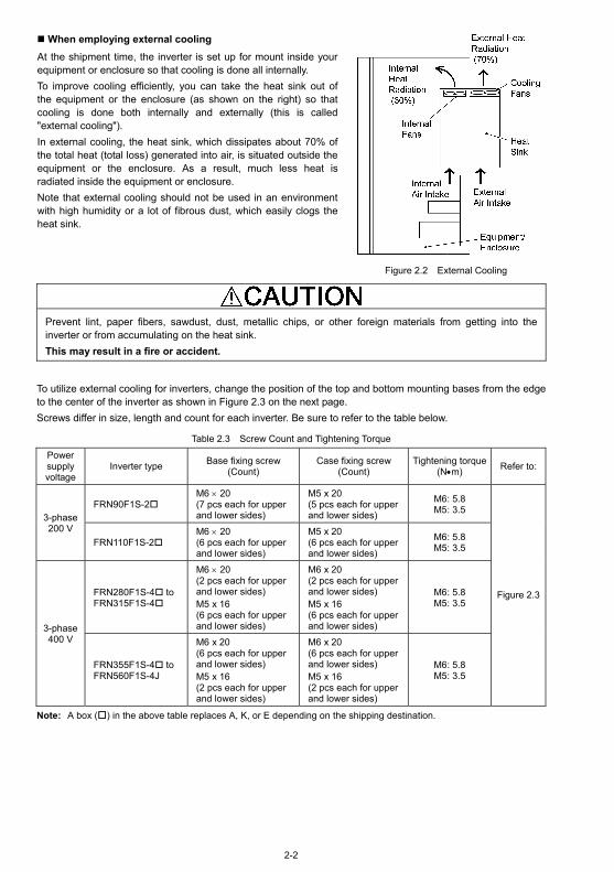
When employing external cooling At the shipment time, the inverter is set up for mount inside your equipment or enclosure so that cooling is done all internally. To improve cooling efficiently, you can take the heat sink out of the equipment or the enclosure (as shown on the right) so that cooling is done both internally and externally (this is called "external cooling"). In external cooling, the heat sink, which dissipates about 70% of the total heat (total loss) generated into air, is situated outside the equipment or the enclosure. As a result, much less heat is radiated inside the equipment or enclosure. Note that external cooling should not be used in an environment with high humidity or a lot of fibrous dust, which easily clogs the heat sink.
Figure 2.2 External Cooling
Prevent lint, paper fibers, sawdust, dust, metallic chips, or other foreign materials from getting into the inverter or from accumulating on the heat sink. This may result in a fire or accident.
To utilize external cooling for inverters, change the position of the top and bottom mounting bases from the edge to the center of the inverter as shown in Figure 2.3 on the next page. Screws differ in size, length and count for each inverter. Be sure to refer to the table below.
Table 2.3 Screw Count and Tightening Torque
Power supply voltage
Inverter type Base fixing screw (Count)
Case fixing screw (Count)
Tightening torque (N•m) Refer to:
FRN90F1S-2 M6 × 20 (7 pcs each for upper and lower sides)
M5 x 20 (5 pcs each for upper and lower sides)
M6: 5.8 M5: 3.5
3-phase 200 V
FRN110F1S-2 M6 × 20 (6 pcs each for upper and lower sides)
M5 x 20 (6 pcs each for upper and lower sides)
M6: 5.8 M5: 3.5
FRN280F1S-4 to FRN315F1S-4
M6 × 20 (2 pcs each for upper and lower sides) M5 x 16 (6 pcs each for upper and lower sides)
M6 x 20 (2 pcs each for upper and lower sides) M5 x 16 (6 pcs each for upper and lower sides)
M6: 5.8 M5: 3.5
3-phase 400 V
FRN355F1S-4 to FRN560F1S-4J
M6 x 20 (6 pcs each for upper and lower sides) M5 x 16 (2 pcs each for upper and lower sides)
M6 x 20 (6 pcs each for upper and lower sides) M5 x 16 (2 pcs each for upper and lower sides)
M6: 5.8 M5: 3.5
Figure 2.3
Note: A box ( ) in the above table replaces A, K, or E depending on the shipping destination.

2-3
1) Remove all of the base fixing screws from the top and bottom of the inverter. Also remove the case fixing screws from the top. (The case fixing screws are not necessary in external cooling. Store them for future use. On the bottom are no case fixing screws.)
2) Secure the top mounting base to the center of the inverter with the base fixing screws, using case fixing screw holes.
3) In the same way, secure the bottom mounting base to the center of the inverter.
Figure 2.3 Relocating the Top and Bottom Mounting Bases
When moving the top and bottom mounting bases, use only the specified screws. A fire or an accident may be caused.
(3) Mounting direction Mount the inverter vertically to the mounting surface and fix it securely with bolts so that the logo "FRENIC-Eco" can be seen from the front.
Do not mount the inverter upside down or horizontally. Doing so will reduce the heat dissipation efficiency of the inverter and cause the overheat protection function to operate, so the inverter will not run.

2-4
2.3 Wiring
Follow the procedure below. (In the following description, the inverter has already been installed.)
2.3.1 Removing and mounting the terminal block (TB) cover and the front cover
(1) For inverters with a capacity of 90 kW or 110 kW
To remove the front cover, loosen the fastening screws on it, hold it with both hands, and slide it upwards and towards you. (See Figure 2.4.)
Put the front cover back in the reverse order of removal. Make sure to properly match the position of the screw holes on both of the front cover and inverter case.
Tightening torque: 3.5 N·m
Figure 2.4 Removing the Front Cover

2-5
(2) For inverters with a capacity of 280 kW to 560 kW
To remove the lower front cover, loosen the fastening screws on it, hold it with both hands, and pull it upwards and towards you.
After removing the lower front cover, you can perform wiring works.
To remove the upper front cover, remove the fastening screws on it while supporting it with one hand and then remove it with both hands. (See Figure 2.5.)
Inverters with a capacity of 355 to 560 kW: Loosen the fastening screws on the upper front cover, hold it with both hands, and pull it upwards and towards you.
Put back the upper and lower front covers in the reverse order of removal. Make sure to properly match the position of the screw holes on the upper and lower front covers and inverter case.
Tightening torque: 3.5 N·m
Figure 2.5 Removing the Front Covers

2-6
2.3.2 Terminal arrangement diagram and screw specifications
The table and figures given below show the terminal screw sizes, tightening torque and terminal arrangements. Note that the terminal arrangements differ depending upon the inverter types. In each of the figures, two grounding terminals ( ) are not exclusive to the power supply wiring (primary circuit) or motor wiring (secondary circuit).
(1) Arrangement of main circuit terminals Table 2.4 Main Circuit Terminals
Power supply voltage
Nominal applied motor
(kW) Inverter type Terminal
screw sizeTightening
torque (N·m)Grounding screw size
Tightening torque (N·m)
90 FRN90F1S-2 Three- phase 200 V 110 FRN110F1S-2
280 FRN280F1S-4
315 FRN315F1S-4
355 FRN355F1S-4
400 FRN400F1S-4
450 FRN450F1S-4
500 FRN500F1S-4
Three- phase 400 V
560 FRN560F1S-4
M12 48 M10 27
Note: A box ( ) in the above table replaces A, K, or E depending on the shipping destination.
Terminal R0, T0: Screw size M3.5, Tightening torque 1.2 N·m Terminal R1, T1: Screw size M3.5, Tightening torque 0.9 N·m
FRN355F1S-4 and FRN400F1S-4
FRN450F1S-4 to FRN560F1S-4
FRN280F1S-4 and FRN315F1S-4
FRN90F1S-2
FRN110F1S-2

2-7
(2) Control circuit terminals (common to all models)
Screw size: M3 Tightening torque: 0.7 N·m
2.3.3 Recommended wire sizes
Table 2.5 lists the recommended wire sizes. Those for the main circuits are examples of using single HIV wires (for 75°C) at an ambient temperature of 50°C.
Table 2.5 Recommended Wire Sizes
Recommended wire size (mm2 ) *1
Main circuits
Main circuit power input(L1/R, L2/S,
L3/T)
Power supply voltage
Nominal applied motor (kW)
Inverter type
w/ DCR
Grounding[ G]
Inverter output
[U, V, W]
Auxiliary power input
(Ctrl. cct.)[R0, T0]
Auxiliary power input
(Fans) [R1, T1]
DCR [P1, P (+)]
Control circuit
90 FRN90F1S-2 150 150 200 Three- phase 200 V 110 FRN110F1S-2 200
38 200
2 2 250
0.75 to
1.25
280 FRN280F1S-4 250 38 325 200 x 2
315 FRN315F1S-4 325 325 200 x 2
355 FRN355F1S-4 200 x 2 200 x 2 250 x 2
400 FRN400F1S-4 200 x 2 250 x 2 250 x 2
450 FRN450F1S-4 250 x 2
60
250 x 2 325 x 2
500 FRN500F1S-4 325 x 2 325 x 2 325 x 2
Three- phase 400 V
560 FRN560F1S-4 250 x 3 100
250 x 3
2 2
325 x 3
0.75 to
1.25
DCR: DC reactor *1 Use a crimp terminal with an insulation sheath or the one processed with an insulation tube.
Use a 600 V, HIV wire with the allowable heat resistance 75°C. This selection assumes the inverter is used in an ambient temperature of 50°C.
Note: A box ( ) in the above table replaces A, K, or E depending on the shipping destination.

2-8
2.3.4 Wiring precautions
Follow the rules below when performing wiring for the inverter. (1) Make sure that the source voltage is within the rated voltage range specified on the nameplate. (2) Be sure to connect the three-phase power wires to the main circuit power input terminals L1/R, L2/S and
L3/T of the inverter. If the power wires are connected to other terminals, the inverter will be damaged when the power is turned on.
(3) Always connect the grounding terminal to prevent electric shock, fire or other disasters and to reduce electric noise.
(4) Use crimp terminals covered with insulated sleeves for the main circuit terminal wiring to ensure a reliable connection.
(5) Keep the power supply wiring (primary circuit) and motor wiring (secondary circuit) of the main circuit, and control circuit wiring as far away as possible from each other.
• When wiring the inverter to the power source, insert a recommended molded case circuit breaker
(MCCB) or earth leakage circuit breaker (ELCB) (with overcurrent protection) in the path of each pair of power lines to inverters. Use the devices recommended ones within the related current range.
• Use wires in the specified size. • Tighten terminals with specified torque. Otherwise, fire could occur.
• Do not connect a surge killer to the inverter's output circuit. • Do not use one multicore cable in order to connect several inverters with motors. Doing so could cause fire.
• Ground the inverter in compliance with the national or local electric code. Otherwise, electric shock or fire could occur.
• Qualified electricians should carry out wiring. • Be sure to perform wiring after turning the power off. Otherwise, electric shock could occur.
• Be sure to perform wiring after installing the inverter. Otherwise, electric shock or injuries could occur.
• Ensure that the number of input phases and the rated voltage of the product match the number of phases and the voltage of the AC power supply to which the product is to be connected.
• Do not connect the power source wires to output terminals (U, V, and W). Doing so could cause fire or an accident.
2.3.5 Wiring for main circuit terminals and grounding terminals
Table 2.6 shows the main circuit terminals and grounding terminals. Table 2.6 Symbols, Names and Functions of the Main Circuit Terminals
Symbol Name Functions
L1/R, L2/S, L3/T Main circuit power inputs
Connect the 3-phase input power lines.
U, V, W Inverter outputs Connect a 3-phase motor. R0, T0 Auxiliary power input for
the control circuit For a backup of the control circuit power supply, connect AC power lines same as that of the main power input.
P1, P(+) DC reactor connection Connect a DC reactor (DCR) for improving power factor. P(+), N(-) DC link bus Connect a DC link bus of other inverter(s). An optional
regenerative converter is also connectable to these terminals. R1, T1 Auxiliary power input for
the fans Normally, no need to use these terminals. Use these terminals for an auxiliary power input of the fans in a power system using a power regenerative PWM converter (RHC series).
G Grounding for inverter and motor
Grounding terminals for the inverter’s chassis (or case) and motor. Earth one of the terminals and connect the grounding terminal of the motor. Inverters provide a pair of grounding terminals that function equivalently.

2-9
Follow the procedure below for wiring and configuration of the inverter. Figure 2.6 illustrates the wiring procedure with peripheral equipment.
Grounding terminals ( G) Inverter output terminals (U, V, W) and motor grounding terminal ( G) DC reactor connection terminals (P1 and P(+))* Switching connectors* (See page 2-11.) DC link bus terminals (P(+) and N(-))* Main circuit power input terminals (L1/R, L2/S and L3/T) Auxiliary power input terminals for the control circuit (R0 and T0)* Auxiliary power input terminals for the fans (R1 and T1)* (See page 2-14.)
* Perform wiring as necessary
Note: A box ( ) in the above figure replaces A, K, or E depending on the shipping destination.
Figure 2.6 Wiring Procedure for Peripheral Equipment
Wiring procedure

2-10
Grounding terminals ( G)
Be sure to ground either of the two grounding terminals for safety and noise reduction. The inverter is designed to use with a safety grounding to avoid electric shock, fire and other disasters. Grounding terminals should be grounded as follows: 1) Ground the inverter in compliance with the national or local electric code. 2) Use a thick grounding wire with a large surface area and keep the wiring length as short as possible.
Inverter output terminals, U, V, W and grounding terminals ( G)
Inverter’s output terminals should be connected as follows: 1) Connect the three wires of the 3-phase motor to terminals U, V, and W, aligning phases each other. 2) Connect the secondary grounding wire to the grounding terminal ( G).
• The wiring length between the inverter and motor should not exceed 50 m, when they are
connected directly. If the wiring length exceeds 50 m, an output circuit filter (option) should be inserted. (E.g. total power cable length is 400 m as shown in the figure below.)
• Do not use one multicore cable to connect several inverters with motors even if some possible combinations of inverters and motors are considered.
• Do not connect a power factor correcting capacitor or surge absorber to the inverter’s output lines
(secondary circuit). • If the wiring length is long, the stray capacitance between the wires will increase, resulting in an
outflow of the leakage current. It will activate the overcurrent protection, increase the leakage current, or will not assure the accuracy of the current display. In the worst case, the inverter could be damaged.
• If more than one motor is to be connected to a single inverter, the wiring length should be the sumof the length of the wires to the motors.
• If an output circuit filter is installed in the inverter or the wires between the motor and the inverter are too long, the actual voltage applied to the motor would drop measurably because of the voltagedrop over the filter or the wires. As a result, the output current may fluctuate because of aninsufficient voltage. In such installations, set the voltage on the higher side, by setting the function code F37 (LoadSelection/Auto torque Boost/Auto energy Saving Operation) to "1: Variable torque load increasing in proportion to square of speed" (Higher start-up torque required), or selecting a non-linear V/f pattern (using the function codes H50 and H51 (Non-linear V/f pattern (Frequency and Voltage)).
• Use an output circuit (secondary) filter of OFL- - A.

2-11
Driving 400 V series motor • If a thermal relay is installed in the path between the inverter and the motor to protect the motor
from overheating, the thermal relay may malfunction even with a wiring length shorter than 50 m. In this situation, add an output circuit filter (option) or lower the carrier frequency (Function code F26).
• If the motor is driven by a PWM-type inverter, surge voltage that is generated by switching the inverter component may be superimposed on the output voltage and may be applied to the motor terminals. Particularly if the wiring length is long, the surge voltage may deteriorate the insulation resistance of the motor. Consider any of the following measures. - Use a motor with insulation that withstands the surge voltage. (All Fuji standard motors feature
insulation that withstands the surge voltage.) - Connect an output circuit filter (option) to the output terminals (secondary circuits) of the
inverter. - Minimize the wiring length between the inverter and motor (10 to 20 m or less).
DC reactor terminals, P1 and P (+)
Connect a DC reactor to terminals P1 and P(+).
• The wiring length should be 10 m or below. • A DC reactor is provided as standard. Be sure to connect the DC reactor except when an optional
converter is connected to the inverter.
Switching connectors
Power switching connectors (CN UX)
The inverter is equipped with a set of switching connectors CU UX (male) which should be configured with a jumper according to the power source voltage and frequency. Set the jumper to U1 or U2 depending upon the power source voltage applied to the main power inputs (L1/R, L2/S, L3/T) or auxiliary power input terminals (R1, T1) for fans, as shown in Figures 2.8 to 2.10.
Fan power supply switching connectors (CN R) and (CN W)
The standard FRENIC-Eco series of inverters also accept DC-linked power input in combination with a power regenerative PWM converter (RHC series). Even when driving the inverter with a DC-linked power, you also need to supply AC power to AC fans and other AC power driven components contained inside. In this case, set up the CN R and CN W on the NC and FAN positions respectively and supply AC power to the auxiliary power input terminals (R1, T1).
For the actual procedure, see Figures 2.8 to 2.10 below.
The fan power supply switching connectors CN R and CN W are set up on the FAN and NC positions respectively by factory default. Do not change the connection unless you drive the inverter with a DC-linked power supply. Wrong connection cannot run the cooling fan, resulting in a heat sink overheating alarm "0h1 " or a charger circuit error alarm "pbf ."

2-12
P1 P(+)
L1/R
L2/S
L3/T
N(-)
+
U
V
W
R1
T1
FAN NC
CN R CN W
Power circuitPCB FAN NC
CN RCN W
Power circuitPCB
R1 L1/R
Inverter Unit
L3/T
T1
Standard configuration- DC-linked power input configuration- PWM converter linked configuration
C
Figure 2.7 Switching Fan Power Source
Setting up the jumpers for the connectors CN UX, CN R and CN W
These switching connectors are located on the power printed circuit board (power PCB) mounted at the right hand side of the control printed circuit board (control PCB) as shown below.
Figure 2.8 Location of Switching Connectors and Auxiliary Power Input Terminals
Figure 2.9 Inserting/Removing the Jumpers
To remove the jumper, pinch its upper side between your fingers, unlock its fastener and pull it up. To insert it, push it down as firmly as it locks with the connector until you will have heard a click sound.
U2 U1
FAN NC
Switching Connectors for Power Input (CN UX)
Switching Connectors for Fans (CN R), (CN W)
Auxiliary Power Input Terminals for Control Circuit

2-13
Figure 2.10 shows how the configuration jumpers of the connectors (CN UX), (CN R) and (CN W) are set up by factory defaults, and how to change their settings for a new power configuration.
Setting up the power switching connector (CN UX)
Connector configuration
Power source voltage
398 to 440 V/50 Hz 430 to 480 V/60 Hz
(Factory default for Taiwan/Korea/EU) Note: Allowable power input voltage range should be within – 15% to +10% of power source voltage.
380 to 398 V/50 Hz 380 to 430 V/60 Hz
(Factory default for Asia) Note: Allowable power input voltage range should be within – 15% to +10% of power source voltage.
Setting up the fan power supply switching connectors (CN R) and (CN W)
Connector configuration
Power system operation
When using no terminal R1, T1 (Factory default)
When using terminals R1, T1 • Feeding the DC-linked power • Combined with a PWM converter
Figure 2.10 Reconfiguration of the (CN UX), (CN R) and (CN W) Connectors
DC link bus terminals, P (+) and N (-)
These are provided for the DC link bus powered system. Connect these terminals with terminals P(+) and N (-) of other inverters.
Consult your Fuji Electric representative if these terminals are to be used.
(CN UX) (Red) (CN UX)
(Red)
(CN R) (Red)
(CN W) (White) (CN W)
(White) (CN R) (Red)

2-14
Main circuit power input terminals, L1/R, L2/S, and L3/T (three-phase input)
1) For safety, make sure that the molded case circuit breaker (MCCB) or magnetic contactor (MC) is turned off before wiring the main circuit power input terminals.
2) Connect the main circuit power supply wires (L1/R, L2/S and L3/T) to the input terminals of the inverter via an MCCB or residual-current-operated protective device (RCD)/earth leakage circuit breaker (ELCB)*, and MC if necessary.
It is not necessary to align phases of the power supply wires and the input terminals of the inverter with each other. * With overcurrent protection
It is recommended that a magnetic contactor be inserted that can be manually activated. This is to allow you to disconnect the inverter from the power supply in an emergency (e.g., when the protective function is activated) so as to prevent a failure or accident from causing the secondary problems.
Auxiliary power input terminals R0 and T0 for the control circuit
In general, the inverter runs normally without power supplied to terminals R0 and T0. If the control circuit shares the power supply with the main circuit, however, activating the protective circuit and turning off the magnetic contactor (MC) in the inverter primary circuit cuts off power to the control circuit, causing alarm signals (30A/B/C) to be lost and the display on the keypad to disappear. To secure input power to the control circuit at all times, supply power to terminals R0 and T0 from the primary circuit of the MC.
Auxiliary power input terminals R1 and T1 for fans
The inverter is equipped with terminals R1 and T1. Only if the inverter works with the DC-linked power input whose source is a power regenerative PWM converter (e.g. RHC series), these terminals are used to feed power to the fans while they are not used in any power system of ordinary configuration. The fan power is:
Single phase 200 to 220 VAC/50 Hz, 200 to 230 VAC/60 Hz for 200 V series 45 kW or above Single phase 380 to 440 VAC/50 Hz. 380 to 480 VAC/60 Hz for 400 V series 55 kW or above
2.3.6 Wiring for control circuit terminals
In general, sheaths and covers of the control signal cables and wires are not specifically designed to withstand a high electric field (i.e., reinforced insulation is not applied). Therefore, if a control signal cable or wire comes into direct contact with a live conductor of the main circuit, the insulation of the sheath or the cover might break down, which would expose the signal wire to a high voltage of the main circuit. Make sure that the control signal cables and wires will not come into contact with live conductors of the main circuit. Failure to observe these precautions could cause electric shock and/or an accident.
Noise may be emitted from the inverter, motor and wires. Take appropriate measure to prevent the nearby sensors and devices from malfunctioning due to such noise. An accident could occur.
Table 2.7 lists the symbols, names and functions of the control circuit terminals. The wiring to the control circuit terminals differs depending upon the setting of the function codes, which reflects the use of the inverter. Route wires properly to reduce the influence of noise, referring to the notes on the following pages.

2-15
Table 2.7 Symbols, Names and Functions of the Control Circuit Terminals
Cla
ssifi
- ca
tion
Symbol Name Functions
[13] Potenti- ometer power supply
Power supply (+10 VDC) for the potentiometer that gives the frequency command (Potentiometer: 1 to 5kΩ) Allowable output current: 10 mA
[12] Voltage input
(1) The frequency is commanded according to the external analog input voltage. 0 to 10 VDC/0 to 100 (%) (Normal mode operation)
10 to 0 VDC/0 to 100 (%) (Inverse mode operation) (2) Used for PID process command signal or its feedback. (3) Used as an additional auxiliary frequency command to be added to one of various
main frequency commands. * Input impedance: 22kΩ * The allowable maximum input voltage is +15 VDC. If the input voltage is +10 VDC
or more, the inverter will interpret it as +10 VDC.
[C1] Current input
(1) The frequency is commanded according to the external analog input current. 4 to 20 mA DC/0 to 100 (%) (Normal mode operation)
20 to 4 mA DC/0 to 100 (%) (Inverse mode operation) (2) Used for PID process command signal or its feedback. (3) Used as an additional auxiliary frequency command to be added to one of various
main frequency commands. * Input impedance: 250Ω * The allowable maximum input current is +30 mA DC. If the input current exceeds
+20 mA DC, the inverter will interpret it as +20 mA DC.
(1) The frequency is commanded according to the external analog input voltage. 0 to 10 VDC/0 to 100 (%) (Normal mode operation)
10 to 0 VDC/0 to 100 (%) (Inverse mode operation) (2) Used for PID process command signal or its feedback. (3) Used as an additional auxiliary frequency command to be added to one of various
main frequency commands. * Input impedance: 22kΩ * The allowable maximum input voltage is +15 VDC. If the input voltage exceeds +10
VDC, however, the inverter will interpret it as +10 VDC.
(4) Connects PTC (Positive Temperature Coefficient) thermistor for motor protection. Ensure that the slide switch SW5 on the control PCB is turned to the PTC position (refer to Section 2.3.7 "Setting up slide switches and handling control circuit terminal symbol plate."
The figure shown at the right illustrates the internal circuit diagram where SW5 (switching the input of terminal [V2] between V2 and PTC) is turned to the PTC position. For details on SW5, refer to Section 2.3.7 "Setting up slide switches and handling control circuit terminal symbol plate." In this case, you must change data of the function code H26.
[V2] Voltage input
Figure 2.11 Internal Circuit Diagram (SW5 Selecting PTC)
Ana
log
inpu
t
[11] Analog common
Two common terminals for analog input and output signal terminals [13], [12], [C1], [V2] and [FMA]. These terminal are electrically isolated from terminals [CM]s and [CMY].

2-16
Table 2.7 Continued C
lass
ifi-
catio
n Symbol Name Functions
- Since low level analog signals are handled, these signals are especially susceptible to the external
noise effects. Route the wiring as short as possible (within 20 m) and use shielded wires. In principle, ground the shielded sheath of wires; if effects of external inductive noises are considerable, connection to terminal [11] may be effective. As shown in Figure 2.12, ground the single end of the shield to enhance the shielding effect.
- Use a twin contact relay for low level signals if the relay is used in the control circuit. Do not connect the relay's contact to terminal [11].
- When the inverter is connected to an external device outputting the analog signal, a malfunction may be caused by electric noise generated by the inverter. If this happens, according to the circumstances, connect a ferrite core (a toroidal core or an equivalent) to the device outputting the analog signal and/or connect a capacitor having the good cut-off characteristics for high frequency between control signal wires as shown in Figure 2.13.
- Do not apply a voltage of +7.5 VDC or higher to terminal [C1]. Doing so could damage the internal control circuit.
Ana
log
inpu
t
[12]
[13]
[11]
Shielded Wire
Potentiometer1 k to 5 kO
<Control Circuit>
[12]
[11]
Ferrite Core
<Control Circuit>Capacitor0.022µ F50V
External AnalogDevice Output
(Pass the same-phasewires through or turnthem around theferrite core 2 or 3times.)
Figure 2.12 Connection of Shielded Wire Figure 2.13 Example of Electric Noise Reduction

2-17
Table 2.7 Continued
Cla
ssifi
- ca
tion Symbol Name Functions
[X1] Digital input 1
[X2] Digital input 2
[X3] Digital input 3
[X4] Digital input 4
[X5] Digital input 5
(1) The various signals such as coast-to-stop, alarm from external equipment, and multistep frequency commands can be assigned to terminals [X1] to [X5], [FWD] and [REV] by setting function codes E01 to E05, E98, and E99. For details, refer to Chapter 5, Section 5.2 "Overview of Function Codes."
(2) Input mode, i.e. Sink/Source, is changeable by using the internal slide switch. (Refer to Section 2.3.7.)
(3) Switches the logic value (1/0) for ON/OFF of the terminals between [X1] to [X5], [FWD] or [REV], and [CM]. If the logic value for ON between [X1] and [CM] is 1 in the normal logic system, for example, OFF is 1 in the negative logic system and vice versa.
(4) The negative logic system never applies to the terminals assigned for (FWD) and (REV).
[FWD] Run forward command
[REV] Run reverse command
(Digital input circuit specifications)
Figure 2.14 Digital Input Circuit
Item Min. Max.
ON level 0 V 2 V Operation voltage (SINK) OFF level 22 V 27 V
ON level 22 V 27 V Operation voltage (SOURCE) OFF level 0 V 2 V
Operation current at ON(Input voltage is at 0V) 2.5 mA 5 mA
Allowable leakage current at OFF - 0.5 mA
[PLC] PLC signal power
Connects to PLC output signal power supply. (Rated voltage: +24 VDC: Allowable range: +22 to +27 VDC) This terminal also supplies a power to the circuitry connected to the transistor output terminals [Y1] to [Y3]. Refer to "Transistor output" described later in this table for more.
Dig
ital i
nput
[CM] Digital common
Two common terminals for digital input signal terminals and output terminal [FMP] These terminals are electrically isolated from the terminals, [11]s and [CMY].
2-18
Table 2.7 Continued C
lass
ifi-
catio
n Symbol Name Functions
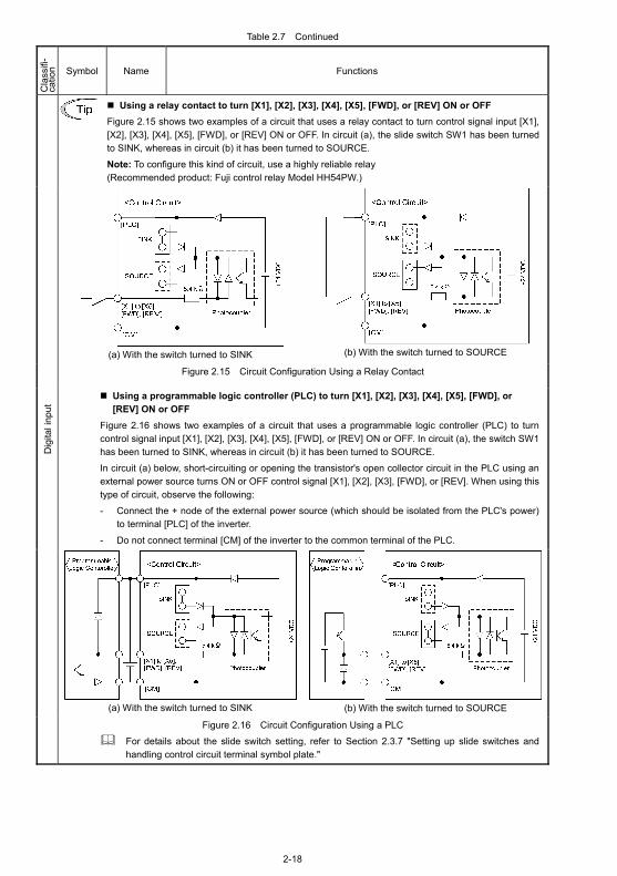
Using a relay contact to turn [X1], [X2], [X3], [X4], [X5], [FWD], or [REV] ON or OFF
Figure 2.15 shows two examples of a circuit that uses a relay contact to turn control signal input [X1], [X2], [X3], [X4], [X5], [FWD], or [REV] ON or OFF. In circuit (a), the slide switch SW1 has been turned to SINK, whereas in circuit (b) it has been turned to SOURCE.
Note: To configure this kind of circuit, use a highly reliable relay (Recommended product: Fuji control relay Model HH54PW.)
(a) With the switch turned to SINK
(b) With the switch turned to SOURCE
Figure 2.15 Circuit Configuration Using a Relay Contact
Using a programmable logic controller (PLC) to turn [X1], [X2], [X3], [X4], [X5], [FWD], or [REV] ON or OFF
Figure 2.16 shows two examples of a circuit that uses a programmable logic controller (PLC) to turn control signal input [X1], [X2], [X3], [X4], [X5], [FWD], or [REV] ON or OFF. In circuit (a), the switch SW1 has been turned to SINK, whereas in circuit (b) it has been turned to SOURCE.
In circuit (a) below, short-circuiting or opening the transistor's open collector circuit in the PLC using an external power source turns ON or OFF control signal [X1], [X2], [X3], [FWD], or [REV]. When using this type of circuit, observe the following:
- Connect the + node of the external power source (which should be isolated from the PLC's power) to terminal [PLC] of the inverter.
- Do not connect terminal [CM] of the inverter to the common terminal of the PLC.
(a) With the switch turned to SINK
(b) With the switch turned to SOURCE
Dig
ital i
nput
Figure 2.16 Circuit Configuration Using a PLC
For details about the slide switch setting, refer to Section 2.3.7 "Setting up slide switches and handling control circuit terminal symbol plate."

2-19
Table 2.7 Continued
Cla
ssifi
- ca
tion
Symbol Name Functions
[FMA] Analog monitor
The monitor signal for analog DC voltage (0 to +10 V) or analog DC current (+4 to +20 mA) is output. You can select either one of the output switching the slide switch SW4 on the control PCB (Refer to Section 2.3.7.), and changing data of the function code F29. You can select one of the following signal functions with function code F31. ・ Output frequency ・ Output current ・ Output voltage ・ Output torque ・ Load factor ・ Input power ・ PID feedback value ・ DC link bus voltage ・ Universal AO ・ Motor output ・ Analog output test ・ PID command ・ PID output
* Input impedance of the external device: Min. 5kΩ (0 to 10 VDC output) Input impedance of the external device: Max. 500Ω (4 to 20 mA DC output) * While the terminal is outputting 0 to 10 VDC, an output less than 0.3 V may become 0.0
V. * While the terminal is outputting 0 to 10 VDC, it is capable of driving up to two meters
with 10 kΩ impedance. While outputting the current, to drive a meter with 500 Ω impedance max. (Adjustable range of the gain: 0 to 200%)
[FMI]* Analog monitor
The monitor signal for analog DC current (+4 to +20 mA) is output. You can select one of the following signal functions with function code F35. ・ Output frequency ・ Output current ・ Output voltage ・ Output torque ・ Load factor ・ Input power ・ PID feedback value ・ DC link bus voltage ・ Universal AO ・ Motor output ・ Analog output test ・ PID command ・ PID output
* Input impedance of the external device: Max. 500Ω * It is capable of driving a meter with a maximum of 500Ω impedance.
(Adjustable gain range: 0 to 200%)
Ana
log
outp
ut
[11] Analog common
Two common terminals for analog input and output signal terminals These terminals are electrically isolated from terminals [CM]s and [CMY].
[FMP]* Pulse monitor
You can select one of the following signal functions with function code F35. ・ Output frequency ・ Output current ・ Output voltage ・ Output torque ・ Load factor ・ Input power ・ PID feedback value ・ DC link bus voltage ・ Universal AO ・ Motor output ・ Analog output test ・ PID command ・ PID output * Input impedance of the external device: Min. 5kΩ * This output is capable of driving up to two meters with 10kΩ impedance. (Driven by the
average DC voltage of the output pulse train.) (Adjustable range of the gain: 0 to 200%) P
ulse
trai
n ou
tput
[CM] Digital common
Two common terminals for digital input signal terminals and an output terminal [FMP]
These terminals are electrically isolated from other common terminals, [11]s and [CMY].
These are the shared terminals with the common terminal [CM]s of the digital inputs.
* The control PCB is equipped with either a screw terminal base or Europe type terminal block, supporting [FMP] or [FMI], respectively. Note that terminals [FMP] and [FMI] cannot coexist in an inverter so that the function code, F35 shares the identical function selection for these terminals.

2-20
Table 2.7 Continued C
lass
ifi-
catio
n Symbol Name Functions
[Y1] Transistor output 1
(1) Various signals such as inverter running, speed/freq. arrival and overload early warning can be assigned to any terminals, [Y1] to [Y3] by setting function code E20, E21 and E22. Refer to Chapter 5, Section 5.2 "Overview of Function Codes" for details.
(2) Switches the logic value (1/0) for ON/OFF of the terminals between [Y1] to [Y3] and [CMY]. If the logic value for ON between [Y1] to [Y3] and [CMY] is 1 in the normal logic system, for example, OFF is 1 in the negative logic system and vice versa.
[Y2] Transistor output 2
Transistor output circuit specification
Figure 2.17 Transistor Output Circuit
Item Max.
ON level 3 V Operation voltage OFF level 27 V
Maximum load current at ON
50 mA
Leakage current at OFF 0.1 mA
Figure 2.18 shows examples of connection between the control circuit and a PLC. [Y3] Transistor output 3
- When a transistor output drives a control relay, connect a surge-absorbing diode across relay’s coil terminals.
- When any equipment or device connected to the transistor output needs to be supplied with DC power, feed the power (+24 VDC: allowable range: +22 to +27 VDC, 50 mA max.) through the [PLC] terminal. Short-circuit between the terminals [CMY] and [CM] in this case.
[CMY] Transistor output common
Common terminal for transistor output signal terminals This terminal is electrically isolated from terminals, [CM]s and [11]s.
Connecting Programmable Controller (PLC) to Terminal [Y1], [Y2] or [Y3] Figure 2.18 shows two examples of circuit connection between the transistor output of the inverter’s control circuit and a PLC. In example (a), the input circuit of the PLC serves as a sink for the control circuit output, whereas in example (b), it serves as a source for the output.
(a) PLC serving as Sink (b) PLC serving as Source
Tran
sist
or o
utpu
t
Figure 2.18 Connecting PLC to Control Circuit

2-21
Table 2.7 Continued
Cla
ssifi
- ca
tion
Symbol Name Functions
[Y5A/C]
General purpose relay output
(1) A general-purpose relay contact output usable as well as the function of the transistor output terminal [Y1], [Y2] or [Y3]. Contact rating: 250 VAC 0.3 A, cos φ = 0.3, 48 VDC, 0.5 A
(2) Switching of the normal/negative logic output is applicable to the following two contact output modes: "Active ON" (Terminals [Y5A] and [Y5C] are closed (excited) if the signal is active.) and "Active OFF" (Terminals [Y5A] and [Y5C] are opened (non-excited) if the signal is active while they are normally closed.).
Rel
ay c
onta
ct o
utpu
t
[30A/B/C] Alarm relay output (for any error)
(1) Outputs a contact signal (SPDT) when a protective function has been activated to stop the motor.
Contact rating: 250 VAC, 0.3A, cos φ = 0.3, 48 VDC, 0.5A (2) Any one of output signals assigned to terminals [Y1] to [Y3] can also be assigned
to this relay contact to use it for signal output. (3) Switching of the normal/negative logic output is applicable to the following two
contact output modes: "Terminals [30A] and [30C] are closed (excited) for ON signal output (Active ON)" or "Terminals [30B] and [30C] are closed (non-excited) for ON signal output (Active OFF)."
Com
mun
icat
ion
RJ-45 connector for the keypad
Standard RJ-45 connector
(1) Used to connect the inverter with PC or PLC using RS485 port. The inverter supplies the power to the keypad through the pins specified below. The extension cable for remote operation also uses wires connected to these pins for supplying the keypad power.
(2) Remove the keypad from the standard RJ-45 connector, and connect the RS485 communications cable to control the inverter through the PC or PLC (Programmable Logic Controller). Refer to Section 2.3.7 "Setting up slide switches and handling control circuit terminal symbol plate" for setting of the terminating resistor.
Figure 2.19 RJ-45 Connector and its Pin Assignment*
* Pins 1, 2, 7, and 8 are exclusively assigned to power lines for the keypad, so do not use those pins for any other equipment.

2-22
Wiring for control circuit terminals
Route the control circuit cable in keeping with the left side panel of the inverter as shown in Figure 2.20. Fasten the control circuit cable to the cable tie support with a cable tie (insulation lock) as shown in Figure
2.20. The hole in the cable tie support is 3.8 mm × 1.5 mm in size. To pass the cable tie through the hole, it
should be 3.8 mm or less in width and 1.5 mm or less in thickness.
Figure 2.20 Routing and Fastening the Control Circuit Cable
- Route the wiring of the control terminals as far from the wiring of the main circuit as possible. Otherwise electric noise may cause malfunctions.
- Fix the control circuit wires inside the inverter to keep them away from the live parts of the main circuit (such as the terminal block of the main circuit).

2-23
2.3.7 Setting up slide switches and handling control circuit terminal symbol plate
Before changing the switches, turn OFF the power and wait at least 10 minutes. Make sure that the LED monitor and charging lamp are turned OFF. Further, make sure, using a multimeter or a similar instrument, that the DC link bus voltage between the terminals P (+) and N (-) has dropped below the safe voltage (+25 VDC). An electric shock may result if this warning is not heeded as there may be some residual electric charge in the DC bus capacitor even after the power has been turned off.
Setting up the slide switches
Switching the slide switches located on the control PCB allows you to customize the operation mode of the analog output terminals, digital I/O terminals, and communications ports. The locations of those switches are shown in Figure 2.23. To access the slide switches, remove the front and terminal block covers and open the keypad enclosure so that you can watch the control PCB. For a screw terminal base, close the control circuit terminal symbol plate since the plate being opened interferes with switching of some switches. See Figures 2.21 and 2.22.
For details on how to remove the front cover, terminal block cover, and keypad enclosure, refer to Section 2.3.1 "Removing and mounting the terminal block (TB) cover and the front cover" and Chapter 1, Section 1.2 "External View and Terminal Blocks," Figure 1.4.
Table 2.8 lists function of each slide switch.
Table 2.8 Function of Each Slide Switch
Switch Function
SW1 Switches the service mode of the digital input terminals between SINK and SOURCE. To make the digital input terminal [X1] to [X5], [FWD] or [REV] serve as a current sink, turn
SW1 to the SINK position. To make them serve as a current source, turn SW1 to the SOURCE position.
Asia Taiwan/Korea EU
Factory default SINK SINK SOURCE
SW3 Switches the terminating resistor of RS485 communications port on the inverter on and off. To connect a keypad to the inverter, turn SW3 to OFF. (Factory default) If the inverter is connected to the RS485 communications network as a terminating device,
turn SW3 to ON.
SW4 Switches the output mode of the analog output terminal [FMA] between voltage and current. When changing this switch setting, also change the data of function code F29.
SW4 Set data of F29 to:
Voltage output (Factory default) VO 0
Current output IO 1
SW5 Switches property of the analog input terminal [V2] for V2 or PTC. When changing this switch setting, also change the data of function code H26.
SW5 Set data of H26 to:
Analog frequency command in voltage (Factory default)
V2 0
PTC thermistor input PTC 1 or 2

2-24
Opening and closing the control circuit terminal symbol plate for the screw terminal base
The symbolic names of the control circuit terminals are marked on the control circuit terminal symbol plate provided on the top of the terminal block. The plate can be opened or closed as necessary. Follow the procedures illustrated below to open or close the plate.
• Opening the plate
Figure 2.21 Opening the Control Circuit Terminal Symbol Plate
Using the handle, pull the plate toward you. Put the plate upright.
• Closing the plate
Figure 2.22 Closing the Control Circuit Terminal Symbol Plate
Using the handle, turn the plate down toward you and push it inward.

2-25
Figure 2.23 shows the location of slide switches for the input/output terminal configuration.
Switching example SW1
SINK SOURCE
SW3
RS485 communication port terminator
ON OFF
Figure 2.23 Location of the Slide Switches
To move a switch slider, use a tool with an approx. 0.8 mm wide tip (e.g., a tip of tweezers). Check that the slider is not in an ambiguous position and it contacts either side of the switch.
2.4 Mounting and Connecting a Keypad
2.4.1 Mounting style and parts needed for connection
(1) Mounting style You can mount a keypad in any style described below.
Mounting a keypad on the enclosure wall (See Figure 2.24.) Installing a keypad at a remote site (e.g. for operation on hand) (See Figure 2.25.)
Figure 2.24 Mounting Keypad on the Enclosure Wall Figure 2.25 Using Keypad at a Remote Site (e.g. for Operation on Hand)
2-26
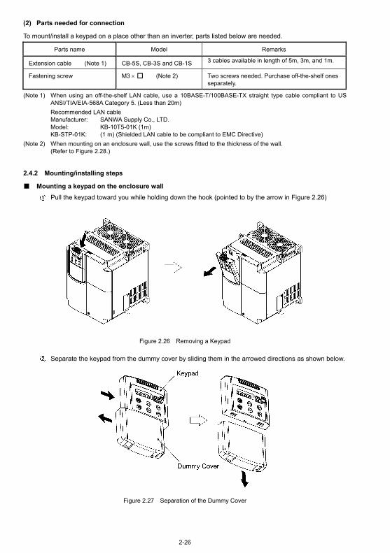
(2) Parts needed for connection
To mount/install a keypad on a place other than an inverter, parts listed below are needed.
Parts name Model Remarks
Extension cable (Note 1) CB-5S, CB-3S and CB-1S 3 cables available in length of 5m, 3m, and 1m.
Fastening screw M3 × (Note 2) Two screws needed. Purchase off-the-shelf ones separately.
(Note 1) When using an off-the-shelf LAN cable, use a 10BASE-T/100BASE-TX straight type cable compliant to US ANSI/TIA/EIA-568A Category 5. (Less than 20m)
Recommended LAN cable Manufacturer: SANWA Supply Co., LTD. Model: KB-10T5-01K (1m) KB-STP-01K: (1 m) (Shielded LAN cable to be compliant to EMC Directive)
(Note 2) When mounting on an enclosure wall, use the screws fitted to the thickness of the wall. (Refer to Figure 2.28.)
2.4.2 Mounting/installing steps
Mounting a keypad on the enclosure wall
Pull the keypad toward you while holding down the hook (pointed to by the arrow in Figure 2.26)
Figure 2.26 Removing a Keypad
Separate the keypad from the dummy cover by sliding them in the arrowed directions as shown below.
Figure 2.27 Separation of the Dummy Cover

2-27
Make a cut-out on the enclosure wall. For details, refer to Chapter 8, Section 8.5.3 "Keypad."
To mount the keypad on the enclosure wall, fix it firmly using a pair of M3 screws put through the taps shown below. (Figure 2.28.) (Tightening torque: 0.7N・m)
Figure 2.28 Mounting a Keypad on the Enclosure Wall
Connect an extension cable (CB-5S, CB-3S or CB-1S) or off-the-shelf straight LAN cable to RJ-45
connectors (Modular jacks) on the keypad and inverter (standard RS485 port.) (Refer to Figure 2.29.)
Figure 2.29 Connecting a Keypad and an Inverter’s Standard RS485 port
Installing a keypad at a remote site (e.g. for operation on hand) Follow step in Mounting a keypad on the enclosure wall.
Putting the keypad back into place Align the bottom of the keypad with the latches (shown below). While holding down the keypad against the terminal block cover (arrow ), push it onto the inverter case (arrow ).
Figure 2.30 Putting the Keypad Back Into Place

2-28
2.5 Cautions Relating to Harmonic Component, Noise, and Leakage Current
(1) Harmonic component Input current to an inverter includes a harmonic component, which may affect other loads and power factor correcting capacitors that are connected to the same power source as the inverter. If the harmonic component causes any problems, connect a DC reactor (option) to the inverter. It may also be necessary to connect an AC reactor to the power factor correcting capacitors.
(2) Noise If noise generated from the inverter affects other devices, or that generated from peripheral equipment causes the inverter to malfunction, follow the basic measures outlined below.
1) If noise generated from the inverter affects the other devices through power wires or grounding wires: - Isolate the grounded metal frames of the inverter from those of the other devices. - Connect a noise filter to the inverter power wires. - Isolate the power system of the other devises from that of the inverter with an insulated transformer.
2) If induction or radio noise generated from the inverter affects other devices through power wires or grounding wires:
- Isolate the main circuit wires from the control circuit wires and other device wires. - Put the main circuit wires through a metal conduit and connect the pipe to the ground near the inverter. - Install the inverter onto the metal switchboard and connect the whole board to the ground. - Connect a noise filter to the inverter power wires.
3) When implementing measures against noise generated from peripheral equipment: - For the control signal wires, use twisted or shielded-twisted wires. When using shielded-twisted wires,
connect the shield of the shielded wires to the common terminals of the control circuit or ground. - Connect a surge absorber in parallel with a coil or solenoid of the magnetic contactor.
(3) Leakage current Harmonic component current generated by insulated gate bipolar transistors (IGBTs) switching on/off inside the inverter becomes leakage current through stray capacitors of inverter input and output wires or a motor. If any of the problems listed below occur, take an appropriate measure against them.
Table 2.9 Leakage Current Countermeasures
Problem Measures
An earth leakage circuit breaker* that is connected to the input (primary) side has tripped. * With overcurrent protection
1) Decrease the carrier frequency. 2) Make the wires between the inverter and motor shorter. 3) Use an earth leakage circuit breaker that has a longer sensitive current than
one currently being used. 4) Use an earth leakage circuit breaker that features measures against
harmonic component (Fuji SG and EG series).
An external thermal relay was activated.
1) Decrease the carrier frequency. 2) Increase the settling current of the thermal relay. 3) Use the electronic thermal relay built in the inverter, instead of an external
thermal relay.

3-25
Chapter 3 OPERATION USING THE KEYPAD 3.4 Programming Mode
3.4.6 Reading maintenance information – Menu #5 "Maintenance Information"
Table 3.18 Display Items for Maintenance Information
LED Monitor shows: Item Description
5_00
Cumulative run time
Shows the content of the cumulative power-ON time counter of the inverter. Unit: thousands of hours. (Display range: 0.001 to 9.999, 10.00 to 65.53) When the total ON-time is less than 10000 hours (display: 0.001 to 9.999), data is shown in units of one hour (0.001). When the total time is 10000 hours or more (display: 10.00 to 65.53), it is shown in units of 10 hours (0.01). When the total time exceeds 65535 hours, the counter will be reset to 0 and the count will start again.
5_01 DC link bus voltage
Shows the DC link bus voltage of the inverter main circuit. Unit: V (volts)
5_02 Max. tempera-ture inside the inverter
Shows a maximum temperature inside the inverter for every hour.
Unit: °C (Temperatures below 20°C are displayed as 20°C.)
5_03 Max. temperature of heat sink
Shows the maximum temperature of the heat sink for every hour. Unit: °C (Temperatures below 20°C are displayed as 20°C.)
5_04 Max. effective output current
Shows the maximum current in RMS for every hour. Unit: A (amperes)
5_05
Capacitance of the DC link bus capacitor
Shows the current capacitance of the DC link bus capacitor (reservoir capacitor) in %, based on the capacitance when shipping as 100%. Refer to Chapter 7 "MAINTENANCE AND INSPECTION" for details. Unit: %
5_06
Cumulative run time of electro-lytic capacitors on printed circuit boards
Shows the content of the cumulative run time counter of the electrolytic capacitors mounted on the printed circuit boards after multiplying the content by the coefficient of the ambient temperature. Unit: thousands of hours. (Display range: 0.001 to 9.999, 10.00 to 99.99) * When the total ON-time is less than 10000 hours (display: 0.001 to 9.999), data is shown in units of one hour (0.001). When the total time is 10000 hours or more (display: 10.00 to 99.99), it is shown in units of 10 hours (0.01). However, when the total time exceeds 99990 hours, the count stops and the display remains at 99.99.
5_07
Cumulative run time of the cooling fan
Shows the content of the cumulative run time counter of the cooling fan. This counter does not work when the cooling fan ON/OFF control (function code H06) is enabled but the fan is stopped. The display method is the same as for "Cumulative run time of electrolytic capacitors on printed circuit boards (5_06 ) above. * When the total time exceeds 99990 hours, the count stops and the display remains at 99.99.
5_08
Number of startups
Shows the content of the cumulative counter of times the inverter is started up (i.e., the number of run commands issued). 1.000 indicates 1000 times. When any number from 0.001 to 9.999 is displayed, the counter increases by 0.001 per startup, and when any number from 10.00 to 65.53 is counted, the counter increases by 0.01 every 10 startups. When the counted number exceeds 65535, the counter will be reset to 0 and the count will start again.
* For inverters with the ROM version 1400 or later: The count range of the cumulative run time counters listed
above has increased to 99.99 (99990 hours). The early warning of lifetime alarm has changed as listed in Table 7.3 in Chapter 7, Section 7.3.1.
The inverter's ROM version can be checked on Menu #5 "Maintenance Information" (5_14).

3-26
Table 3.18 Display Items for Maintenance Information (Continued)
LED Monitor shows: Item Description
5_09
Input watt-hour Shows the input watt-hour of the inverter.
Unit: 100 kWh (Display range: 0.001 to 9999)
Depending on the value of integrated input watt-hour, the decimal point on the LED monitor shifts to show it within the LED monitors’ resolution (e.g. the resolution varies between 0.001, 0.01, 0.1 or 1). To reset the integrated input watt-hour and its data, set function code E51 to "0.000."
When the input watt-hour exceeds 1000000 kWh, it returns to "0."
5_10
Input watt-hour data
Shows the value expressed by "input watt-hour (kWh)× E51 (whose data range is 0.000 to 9999)."
Unit: None.
(Display range: 0.001 to 9999. The data cannot exceed 9999. (It will be fixed at 9999 once the calculated value exceeds 9999.))
Depending on the value of integrated input watt-hour data, the decimal point on the LED monitor shifts to show it within the LED monitors’ resolution.
To reset the integrated input watt-hour data, set function code E51 to "0.000."
5_11 No. of RS485 errors (stan-dard)
Shows the total number of errors that have occurred in standard RS485 commu-nication (via the RJ-45 connector as standard) since the power is turned on. Once the number of errors exceeds 9999, the count returns to 0.
5_12
Content of RS485 commu-nications error (standard)
Shows the latest error that has occurred in standard RS485 communication in decimal format. For error contents, refer to the RS485 Communication User’s Manual (MEH448a).
5_13 No. of option errors
Shows the total number of optional communications card errors since the power is turned on. Once the number of errors exceeds 9999, the count returns to 0.
5_14 Inverter's ROM version
Shows the inverter's ROM version as a 4-digit code.
5_16 Keypad's ROM version
Shows the keypad's ROM version as a 4-digit code.
5_17 No. of RS485 errors (option)
Shows the total number of errors that have occurred in optional RS485 commu-nication since the power is turned on. Once the number of errors exceeds 9999, the count returns to 0.
5_18
Content of RS485 commu-nications error (option)
Shows the latest error that has occurred in optional RS485 communication in decimal format. For error contents, refer to the RS485 Communication User’s Manual (MEH448a).
5_19 Option's ROM version
Shows the option's ROM version as a 4-digit code.
5_23 Cumulative motor run time
Shows the content of the cumulative power-ON time counter of the motor.
The display method is the same as for "Cumulative run time (5_00 ) above.

5-8
Chapter 5 FUNCTION CODES 5.1 Function Code Tables
Code Name Data setting range Incre-ment Unit
Change when
running
Data copying
Default setting
Refer to
page:
E20 Signal Assignment to: (Transistor signal) [Y1]
— — N Y 0
E21 [Y2] — — N Y 1
E22 [Y3] — — N Y 2
E24 (Relay contact signal) [Y5A/C]
— — N Y 15 (10) *1
E27 [30A/B/C]
Selecting function code data assigns the corresponding function to terminals [Y1] to [Y3], [Y5A/C], and [30A/B/C] as listed below. Setting the value of 1000s in parentheses ( ) shown below assigns a negative logic input to a terminal. 0 (1000): Inverter running (RUN)1 (1001): Frequency arrival signal (FAR)2 (1002): Frequency detected (FDT)3 (1003): Undervoltage detected
(Inverter stopped) (LU)5 (1005): Inverter output limiting (IOL)6 (1006): Auto-restarting after momentary
power failure (IPF)7 (1007): Motor overload early warning (OL)10 (1010): Inverter ready to run (RDY)11: Switch motor drive source between
commercial power and inverter output (For MC on commercial line) (SW88)
12: Switch motor drive source between commercial power and inverter output (For secondary side) (SW52-2)
13: Switch motor drive source between commercial power and inverter output (For primary side) (SW52-1)
15 (1015): Select AX terminal function (For MC on primary side) (AX)
25 (1025): Cooling fan in operation (FAN)26 (1026): Auto-resetting (TRY)27 (1027): Universal DO (U-DO)28 (1028): Heat sink overheat early warning (OH)30 (1030): Service life alarm (LIFE)33 (1033): Command loss detected (REF OFF)35 (1035): Inverter output on (RUN2)36 (1036): Overload prevention control (OLP)37 (1037): Current detected (ID)42 (1042): PID alarm (PID-ALM)43 (1043): Under PID control (PID-CTL)44 (1044): Motor stopping due to slow
flowrate under PID control (PID-STP)45 (1045): Low output torque detected (U-TL)54 (1054): Inverter in remote operation (RMT)55 (1055): Run command activated (AX2)56 (1056): Motor overheat detected (PTC) (THM)59 (1059): Terminal [C1] wire break (C1OFF)60 (1060): Mount motor 1, inverter-driven (M1_I)61 (1061): Mount motor 1,
commercial-power-driven (M1_L)62 (1062): Mount motor 2, inverter-driven (M2_I)63 (1063): Mount motor 2,
commercial-power-driven (M2_L)64 (1064): Mount motor 3, inverter-driven (M3_I)65 (1065): Mount motor 3,
commercial-power-driven (M3_L)67 (1067): Mount motor 4,
commercial-power-driven (M4_L)68 (1068): Periodic switching early warning (MCHG)69 (1069): Pump control limit signal (MLIM)99 (1099): Alarm output (for any alarm) (ALM)
— — N Y 99
5-52
*1 Values in parentheses ( ) in the above table denote default settings for the EU version.

5-9
Code Name Data setting range Incre-ment Unit
Change when
running
Data copying
Default setting
Refer to
page:
E31 Frequency Detection (FDT) (Detection level)
0.0 to 120.0 0.1 Hz Y Y 60.0 (50.0) *2
5-57-1
E32 (Hysteresis width) 0.0 to 120.0 0.1 Hz Y Y 1.0 5-57-1
E34 Overload Early Warning /Current Detection (Level)
0: (Disable) Current value of 1 to 150% of the inverter rated current
0.01 A Y Y1 Y2
100% of the motor rated current
E35 (Timer) 0.01 to 600.00 *1 0.01 s Y Y 10.00
5-58
E40 PID Display Coefficient A
-999 to 0.00 to 999 *1 0.01 — Y Y 100
E41 PID Display Coefficient B
-999 to 0.00 to 999 *1 0.01 — Y Y 0.00
E43 LED Monitor (Item selection)
0: Speed monitor (Select by E48.) 3: Output current 4: Output voltage 8: Calculated torque 9: Input power 10: PID process command (Final) 12: PID feedback value 14: PID output 15: Load factor 16: Motor output 17: Analog input
— — Y Y 0
E45 LCD Monitor *3 (Item selection)
0: Running status, rotational direction and operation guide
1: Bar charts for output frequency, current and calcu-lated torque
— — Y Y 0
E46 (Language selection) 0: Japanese 1: English 2: German 3: French 4: Spanish 5: Italian
— — Y Y 1
E47 (Contrast control) 0 (Low) to 10 (High) 1 — Y Y 5
E48 LED Monitor (Speed monitor item)
0: Output frequency 3: Motor speed in r/min 4: Load shaft speed in r/min 7: Display speed in %
— — Y Y 0
E50 Coefficient for Speed Indication
0.01 to 200.00 *1 0.01 — Y Y 30.00
—
E51 Display Coefficient for Input Watt-hour Data
0.000: (Cancel/reset) 0.001 to 9999
0.001 — Y Y 0.010 5-58
E52 Keypad (Menu display mode)
0: Function code data editing mode (Menus #0, #1 and #7)
1: Function code data check mode (Menus #2 and #7)2: Full-menu mode (Menus #0 through #7)
— — Y Y 0 —
The shaded function codes ( ) are applicable to the quick setup. *1 When you make settings from the keypad, the incremental unit is restricted by the number of digits that the LED
monitor can display. (Example) If the setting range is from -200.00 to 200.00, the incremental unit is: "1" for -200 to -100, "0.1" for -99.9 to -10.0 and for 100.0 to 200.0, and "0.01" for -9.99 to -0.01 and for 0.00 to 99.99. *2 Values in parentheses ( ) in the above table denote default settings for the EU version. *3 LCD monitor settings are applicable only to the inverter equipped with a multi-function keypad.

5-16
Code Name Data setting range Incre-ment Unit
Change when
running
Data copying
Default setting
Refer to
page:
H80 Gain for Suppression of Output Current Fluctua-tion for Motor
0.00 to 0.40 0.01 — Y Y *3 Depending on the inverter capac-ity
H86 Reserved. *2 0 to 2 1 — Y Y1 Y2
*4 Depending on the inverter capac-ity
H87 Reserved. *2 25.0 to 120.0 0.1 Hz Y Y 25.0
H88 Reserved. *2 0 to 3, 999 1 — Y N 0
H89 Reserved. *2 0, 1 — — Y Y 0
H90 Reserved. *2 0, 1 — — Y Y 0
—
H91 PID Feedback Wire Break Detection
0.0: Disable alarm detection 0.1 to 60.0 s: Wire break detection time
0.1 s Y Y 0.0 5-74
H92 Continue to Run (P-component: gain)
0.000 to 10.000. 999 *1 0.001 Times Y Y1 Y2
999
H93 (I-component: time) 0.010 to 10.000, 999 *1 0.001 s Y Y1 Y2
999
—
H94 Cumulative Run Time of Motor
Change or reset the cumulative data — — N N — 5-74
H95 DC Braking (Braking response mode)
0: Slow 1: Quick
— — Y Y 1 5-40
Data STOP key priority Start check function
0: Disable Disable
1: Enable Disable
2: Disable Enable
H96 STOP Key Priority/ Start Check Function
3: Enable Enable
— — Y Y 0 —
H97 Clear Alarm Data Setting H97 data to "1" clears alarm data and then returns to zero.
— — Y N 0
H98 Protection/ Maintenance Function
0 to 63: Display data on the keypad's LED monitor in decimal format (In each bit, "0" for disabled, "1" for enabled.)
Bit 0: Lower the carrier frequency automatically Bit 1: Detect input phase loss Bit 2: Detect output phase loss Bit 3: Select life judgment criteria of DC link bus
capacitor Bit 4: Judge the life of DC link bus capacitor Bit 5: Detect DC fan lock
— — Y Y 19 (Bits 4, 1, 0 = 1 Bits 5, 3, 2 = 0)
5-75
*1 When you make settings from the keypad, the incremental unit is restricted by the number of digits that the LED monitor can display.
(Example) If the setting range is from -200.00 to 200.00, the incremental unit is: "1" for -200 to -100, "0.1" for -99.9 to -10.0 and for 100.0 to 200.0, and "0.01" for -9.99 to -0.01 and for 0.00 to 99.99. *2 The H86 through H91 are displayed, but they are reserved for particular manufacturers. Unless otherwise specified, do
not access these function codes. *3 Select 0.10 for models of 45 kW or above (200 V series) and 55 kW or above (400 V series), 0.20 for models of 37 kW
or below (200 V series) and 45 kW or below (400 V series). *4 Select 2 for models of 45 kW or above (200 V series) and 55 kW or above (400 V series), 0 for models of 37 kW or
below (200 V series) and 45 kW or below (400 V series).
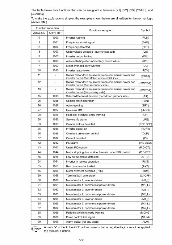
5-53
The table below lists functions that can be assigned to terminals [Y1], [Y2], [Y3], [Y5A/C], and [30A/B/C]. To make the explanations simpler, the examples shown below are all written for the normal logic (Active ON.)
Function code data
Active ON Active OFF Functions assigned Symbol
0 1000 Inverter running (RUN)
1 1001 Frequency arrival signal (FAR)
2 1002 Frequency detected (FDT)
3 1003 Undervoltage detected (Inverter stopped) (LU)
5 1005 Inverter output limiting (IOL)
6 1006 Auto-restarting after momentary power failure (IPF)
7 1007 Motor overload early warning (OL)
10 1010 Inverter ready to run (RDY)
11 - Switch motor drive source between commercial power and inverter output (For MC on commercial line)
(SW88)
12 - Switch motor drive source between commercial power and inverter output (For secondary side)
(SW52-2)
13 - Switch motor drive source between commercial power and inverter output (For primary side)
(SW52-1)
15 1015 Select AX terminal function (For MC on primary side) (AX)
25 1025 Cooling fan in operation (FAN)
26 1026 Auto-resetting (TRY)
27 1027 Universal DO (U-DO)
28 1028 Heat sink overheat early warning (OH)
30 1030 Service life alarm (LIFE)
33 1033 Command loss detected (REF OFF)
35 1035 Inverter output on (RUN2)
36 1036 Overload prevention control (OLP)
37 1037 Current detected (ID)
42 1042 PID alarm (PID-ALM)
43 1043 Under PID control (PID-CTL)
44 1044 Motor stopping due to slow flowrate under PID control (PID-STP)
45 1045 Low output torque detected (U-TL)
54 1054 Inverter in remote operation (RMT)
55 1055 Run command activated (AX2)
56 1056 Motor overheat detected (PTC) (THM)
59 1059 Terminal [C1] wire break (C1OFF)
60 1060 Mount motor 1, inverter-driven (M1_I)
61 1061 Mount motor 1, commercial-power-driven (M1_L)
62 1062 Mount motor 2, inverter-driven (M2_I)
63 1063 Mount motor 2, commercial-power-driven (M2_L)
64 1064 Mount motor 3, inverter-driven (M3_I)
65 1065 Mount motor 3, commercial-power-driven (M3_L)
67 1067 Mount motor 4, commercial-power-driven (M4_L)
68 1068 Periodic switching early warning (MCHG)
69 1069 Pump control limit signal (MLIM)
99 1099 Alarm output (for any alarm) (ALM)
A mark "-" in the Active OFF column means that a negative logic cannot be applied to the terminal function.

5-54
Inverter running -- (RUN) (Function code data = 0)
This output signal is used to tell the external equipment that the inverter is running at a starting frequency or higher. It comes ON when the output frequency exceeds the starting frequency, and it goes OFF when it is less than the stop frequency. It is also OFF when the DC braking is in operation. If this signal is assigned in negative logic (Active OFF), it can be used as a signal indicating "inverter being stopped."
Frequency arrival signal -- (FAR) (Function code data = 1)
This output signal comes ON when the difference between the output frequency and reference frequency comes within the allowable error zone. (prefixed to 2.5 Hz).
Frequency detected -- (FDT) (Function code data = 2)
This output signal comes ON when the output frequency exceeds the frequency detection level specified by function code E31, and it goes OFF when the output frequency drops below the "Detection level (E31) - Hysteresis width (E32)."
Undervoltage detected -- (LU) (Function code data = 3)
This output signal comes ON when the DC link bus voltage of the inverter drops below the specified undervoltage level, and it goes OFF when the voltage exceeds the level. This signal is ON also when the undervoltage protective function is activated so that the motor is in an abnormal stop state (e.g., tripped). When this signal is ON, a run command is disabled if given.
Inverter output limiting -- (IOL) (Function code data = 5)
This output signal comes ON when the inverter is limiting the output frequency by activating any of the following actions (minimum width of the output signal: 100 ms).
• Current limiting by software (F43 and F44: Current limiter (Mode selection) and (Level)) • Instantaneous overcurrent limiting by hardware (H12 = 1) • Automatic deceleration (H69 = 3))
When the (IOL) signal is ON, it may mean that the output frequency may have deviated from (or dropped below) the frequency specified by the frequency command because of this limiting function.
Auto-restarting after momentary power failure -- (IPF)
(Function code data = 6)
This output signal is ON either during continuous running after a momentary power failure or during the period from when the inverter has detected an undervoltage condition and shut down the output until restart has been completed (the output has reached the reference frequency). To enable this (IPF) signal, set F14 (Restart mode after momentary power failure) to "3: Enable restart (Continue to run)," "4: Enable restart (Restart at the frequency at which the power failure occurred)," or "5: Enable restart (Restart at the starting frequency)" beforehand.

5-57
Inverter output on -- (RUN2) (Function code data = 35)
This output signal comes ON when the inverter is running at the starting frequency or below or the DC braking is in operation.
Overload prevention control -- (OLP) (Function code data = 36)
This output signal comes ON when the overload prevention control is activated. The minimum ON-duration is 100 ms.
For details of the overload prevention control, refer to the descriptions of function code H70.
Current detected -- (ID) (Function code data = 37)
This output signal comes ON when the output current of the inverter exceeds the level specified by E34 (Current detection (Level)) for the time longer than the one specified by E35 (Current detection (Timer)). The minimum ON-duration is 100 ms.
This signal goes OFF when the output current drops below 90% of the rated operation level.
Function code E34 is effective for not only the motor overload early warning (OL), but also for the operation level of the current detection (ID).
For details of the current detection, refer to the descriptions of function codes E34 and E35.
Low output torque detected -- (U-TL) (Function code data = 45)
This output signal comes ON when the torque value calculated by the inverter decreases below the level specified by E80 (Detect low torque (Detection level)) for the time longer than the one specified by E81 (Detect low torque (Timer)). The minimum ON-duration is 100 ms.
For details of the low output torque detection, refer to the description of function codes E80 and E81.
Inverter in remote operation -- (RMT)
(Function code data = 54)
This output signal comes ON when the inverter switches from local to remote mode.
For details about the remote and local modes, refer to Chapter 3, Section 3.3.3 "Switching between remote and local modes."
Terminal [C1] wire break -- (C1OFF)
(Function code data = 59)
This output signal comes ON when the inverter detects that the input current (after filtered with C38) on analog input terminal [C1] drops below 2 mA, interpreting it as a terminal [C1] wire broken.
Alarm output (for any alarm) -- (ALM) (Function code data = 99)
This output signal comes ON if any of the protective functions is activated and the inverter enters Alarm mode.

5-57-1
E31, E32 Frequency Detection (Detection level and Hysteresis width)
If the output frequency exceeds the frequency detection level specified by E31, the FDT signal comes ON; if it drops below the "Frequency detection level (E31) minus hysteresis width (E32)," it goes OFF. It is necessary to assign the signal (FDT) to one of the output terminals Y1 to Y3, Y5A/C, and 30A/B/C using any of E20 to E22, E24, and E27 (data = 2). - Data setting range: 0.0 to 120.0 (Hz)

5-74
H69 Automatic Deceleration
H69 specifies whether automatic deceleration control is to be enabled or disabled. During de-celeration of the motor, if regenerative energy exceeds the level that can be handled by the in-verter, overvoltage trip may happen. With automatic deceleration enabled, when the DC link bus voltage exceeds the level (internally fixed) for starting automatic deceleration, the output fre-quency is controlled to prevent the DC link bus voltage from rising further; thus regenerative energy is suppressed.
If automatic deceleration is enabled, deceleration may take a longer time. This is designed to limit the torque during deceleration, and is therefore of no use where there is a braking load.
Disable the automatic deceleration when a braking unit is connected. The automatic deceleration control may be activated at the same time when a braking unit starts operation, which may make the acceleration time fluctuate. In case the set deceleration time is so short, the DC link bus voltage of the inverter rises quickly, and consequently, the automatic deceleration may not follow the voltage rise. In such a case, prolong the deceleration time.
Even if the time period of 3 times of the deceleration time 1 (F08) has elapsed after the inverter entered automatic deceleration, there may be a case that the motor does not stop or the frequency dose not decrease. In this case, cancel the automatic decelera-tion forcibly for safety and decelerate the motor according to the set deceleration time. Prolong the deceleration time also.
H70 Overload Prevention Control
H70 specifies the rate of decreasing the output frequency to prevent an overload condition. Under this control, an overload trip is prevented by decreasing the output frequency of the in-verter before the inverter trips because of the overheating of the cooling fan or the overloading of the inverter (with an alarm indication of 0h1 or 0lu ). This control is useful for facilities such as pumps where a decrease in the output frequency leads to a decrease in the load and it is nec-essary to keep the motor running even when the output frequency goes low.
Data for H70 Function
0.00 Decelerate the motor by deceleration time 1 specified by F08
0.01 to 100.0 Decelerate the motor by deceleration rate 0.01 to 100.0 (Hz/s)
999 Disable overload prevention control
In applications where a decrease in the output frequency does not lead to a decrease in the load, this function is of no use and should not be enabled.

5-74-1
H91 PID Feedback Wire Break Detection
Using the analog input terminal [C1] (current input) for feedback signals under PID control (E62 = 5) enables wire break detection and alarm (cof ) issuance. H91 specifies whether to enable the wire break detection or the duration of less than 2 mA on the terminal [C1]*.
If the inverter detects that the input current on [C1] is less than 2 mA (after filtered with C38) for the duration specified by H91, it interprets the state as a terminal [C1] wire break and issues an alarm (cof ).
- Data setting range: 0.0 (Disable alarm detection) 0.1 to 60.0 s (If the current level is less than 2 mA for this duration, detect wire break and issue cof alarm.) *It is also possible to assign the signal (C1OFF) to one of the output terminals Y1 to Y3, Y5A/C, and 30A/B/C using any of E20 to E22, E24, and E27 (data = 59). The C1OFF goes ON if the input current level (after filtered with C38) on [C1] drops below 2 mA, and it goes OFF if the current level rises to 2 mA or above.
H94 Cumulative Run Time of Motor
You can view the cumulative run time of the motor on the keypad. This feature is useful for management and maintenance of the mechanical system. With this function code (H94), you can set the cumulative run time of the motor to any value you choose. For example, by specifying "0," you can clear the cumulative run time of the motor.
The data for H94 is in hexadecimal notation. Check the cumulative run time of the motor on the keypad.

7-3
Chapter 7 MAINTENANCE AND INSPECTION 7.3 List of Periodical Replacement Parts Each part of the product has its own service life that will vary according to the environmental and operating conditions. It is recommended that the following parts be replaced as specified below. When the replacement is necessary, contact your Fuji Electric representative.
Table 7.2 Replacement Parts
Standard replacement intervals Part name
Old specifications New specifications
DC link bus capacitor 7 years 10 years Electrolytic capacitors on printed circuit boards 7 years 10 years
Cooling fan 7 years (5.5 kW or below) 4.5 years (7.5 to 30 kW) 3 years (37 kW or above)
10 years (5.5 kW or below) 10 years (7.5 to 30 kW) 7 years (37 kW or above)
Fuse 10 years (90 kW or above) 10 years (90 kW or above)
(Note) These replacement intervals are based on the estimated service life of the inverter at an ambient temperature of 40°C under 80% of full load. In environments with an ambient temperature above 40°C or a large amount of dust or dirt, the replacement intervals may need to be reduced.
7.3.1 Judgment on service life
(1) Viewing data necessary for judging service life; Measurement procedures Through Menu #5 "Maintenance Information" in Programming mode, you can view on the keypad various data (as a guideline) necessary for judging whether key components such as the DC link bus capacitor, the electrolytic capacitors on the printed circuit boards, and the cooling fan are approaching their service life.
-1 Measuring the capacitance of the DC link bus capacitor (in comparison with that at factory shipment) Measure the capacitance of the DC link bus capacitor according to the procedure given below. The result will be displayed on the keypad as a ratio (%) to the initial capacitance at the time of factory shipment. ----------------------------------------------- Procedure for measuring capacitance ----------------------------------------------- 1) To ensure validity in the comparative measurement, put the condition of the inverter back to the state at
factory shipment. • Remove the option card (if already in use) from the inverter. • In case another inverter is connected via the DC link bus to the P(+) and N(-) terminals of the main circuit,
disconnect the wires. (You do not need to disconnect a DC reactor (optional), if any.) • Disconnect power wires for the auxiliary input to the control circuit (R0, T0). • In case the standard keypad has been replaced with a multi-function keypad after the purchase, put back
the original standard keypad. • Turn OFF all the digital input signals fed to terminals [FWD], [REV], and [X1] through [X5] of the control
circuit. • If a potentiometer is connected to terminal [13], disconnect it. • If an external apparatus is attached to terminal [PLC], disconnect it. • Ensure that transistor output signals ([Y1] - [Y3]) and relay output signals ([Y5A/C] and [30A/B/C]) will not
be turned ON.
If negative logic is specified for the transistor output and relay output signals, they are considered ON when the inverter is not running. Specify positive logic for them.
• Keep the ambient temperature within 25 ±10°C. 2) Switch ON the main circuit power. 3) Confirm that the cooling fan is rotating and the inverter is in stopped state. 4) Switch OFF the main circuit power. 5) Start the measurement of the capacitance of the DC link bus capacitor. Make sure that " . . . . " appears on the
LED monitor.
If " . . . . " does not appear on the LED monitor, the measurement will not start. Check theconditions listed in 1).
6) Once " . . . . " has disappeared from the LED monitor, switch ON the main circuit power again. 7) Select Menu #5 "Maintenance Information" in Programming mode and note the reading (relative capacitance
(%) of the DC link bus capacitor). ----------------------------------------------------------------------------------------------------------------------------------------------------

7-5
(2) Early warning of lifetime alarm For the components listed in Table 7.3, you can get an early warning of lifetime alarm at one of the transistor output terminals ([Y1] to [Y3]) and the relay contact terminals ([Y5A] - [Y5C], and [30A/B/C]) as soon as any of the conditions listed under the "Judgment level" column has been exceeded. Note that the judgment level differs depending upon the inverter's ROM version. The early warning signal is also turned ON when a lock condition on the internal air circulation DC fan (on 200V series inverters with a capacity of 45 kW or above; on 400V series inverters with a capacity of 55 kW or above) has been detected.
Table 7.3 Criteria for Issuing a Lifetime Alarm
Inverter's ROM version 1399 or earlier 1400 or later Parts to be replaced Judgment level
Remarks
DC link bus capacitor 85% or lower of the capacitance than that of the factory setting Electrolytic capacitors on printed circuit boards
61000 hours or longer as accumulated run time
87000 hours or longer as accumulated run time
Accumulated run time ≥ 61000 hours
Accumulated run time ≥ 87000 hours
5.5 kW or below
Accumulated run time ≥ 40000 hours
Accumulated run time ≥ 87000 hours
7.5 to 30 kW
Accumulated run time ≥ 25000 hours
Accumulated run time ≥ 61000 hours
37 kW or above
Cooling fan
(Estimated service life at the inverter’s ambient temperature of 40°C under 80% of full load)
The inverter's ROM version can be checked on Menu #5 "Maintenance Information" (5_14).
7.4 Measurement of Electrical Amounts in Main Circuit
Because the voltage and current of the power supply (input, primary circuit) of the main circuit of the inverter and those of the motor (output, secondary circuit) include harmonic components, the readings may vary with the type of the meter. Use meters indicated in Table 7.4 when measuring with meters for commercial frequencies. The power factor cannot be measured by a commercially available power-factor meter that measures the phase difference between the voltage and current. To obtain the power factor, measure the power, voltage and current on each of the input and output sides and calculate in the following formula.
Three-phase input
%100×(A)t(V)×Curren×Voltage3
(W)powerElectric=factorPower
Table 7.4 Meters for Measurement of Main Circuit
Item
Input (primary) side Output (secondary) side DC link bus
voltage (P (+)-N (-))
Wav
efor
m Voltage
Current Voltage Current
Nam
e of
m
eter
Ammeter AR, AS, AT
Voltmeter VR, VS, VT
Wattmeter WR, WT
Ammeter AU, AV, AW
Voltmeter VU, VV, VW
Wattmeter WU, WW
DC voltmeter V
Type
of
met
er
Moving iron type
Rectifier or moving iron
type
Digital AC power meter
Digital AC power meter
Digital AC power meter
Digital AC power meter Moving coil type
Sym
bol
of m
eter
⎯ ⎯ ⎯ ⎯
It is not recommended that meters other than a digital AC power meter be used for measuring the output voltage or output current since they may cause larger measurement errors or, in the worst case, they may be damaged.

8-1
Chapter 8 SPECIFICATIONS 8.1 Standard Models
8.1.1 Three-phase 200 V series
Note: A box ( ) in the above table replaces A, K, or E depending on the shipping destination.

8-2
8.1.2 Three-phase 400 V series
Note: A box ( ) in the above table replaces A, K, or E depending on the shipping destination.

8-3
Note: A box ( ) in the above table replaces A, K, or E depending on the shipping destination.

8-8
8.4 Terminal Specifications 8.4.1 Terminal functions For details about the main and control circuit terminals, refer to Chapter 2, Section 2.3.5 and Section 2.3.6 (Table 2.7), respectively.

8-9
8.4.2 Running the inverter with keypad
(Note 1) When connecting a DC reactor (DCR), first remove the short bar between terminals [P1] and [P+]. A DCR is optional for inverters below 75 kW but standard for inverters of 75 kW or above. For inverters of 75 kW or above, be sure to connect a DCR.
(Note 2) To protect wiring, insert a molded case circuit breaker (MCCB) or an earth leakage circuit breaker (ELCB) (with overcurrent protection) of the type recommended for the inverter between the commercial power supply and the inverter. Do not use a circuit breaker with a capacity exceeding the recommended capacity.
(Note 3) In addition to an MCCB or ELCB, insert, if necessary, a magnetic contactor (MC) of the type recommended for the inverter to cut off the commercial power supply to the inverter. Furthermore, if the coil of the MC or solenoid comes into close contact with the inverter, install a surge absorber in parallel.
(Note 4) To put the inverter on standby by making the control circuit only active with the main circuit power supply being opened, connect this pair of wires to terminals [R0] and [T0]. Without connecting this pair of wires to these terminals, you can still run the inverter as long as the main wires of the commercial power supply to the main circuit are properly connected.
(Note 5) Normally no need to be connected. Use these terminals when the inverter is equipped with a high power factor PWM converter with a regenerative facility.
(Note 6) The inverter has either [FMP] or [FMI] depending on the type of the control printed circuit board (control PCB).

8-12 to 8-14
8.5 External Dimensions
8.5.1 Standard models
Dimensions (mm)Power supply voltage Inverter type
W W1 W2 H H1 H2 D D1 D2 D3 ΦA FRN90F1S-2 530 430 750 720 15.5 380 240 140 4 2x15 Three-phase
200 V FRN110F1S-2 680 290 880 850 15.5 395 255 140 4 3x15 FRN280F1S-4 FRN315F1S-4
1000 970 380 200 180
FRN355F1S-4 FRN400F1S-4
680 290 3x15
FRN450F1S-4 FRN500F1S-4
Three-phase 400 V
FRN560F1S-4 880 260
15
1400 137015.5
440 260 180 6.4
4x15
Note: A box ( ) in the above table replaces A, K, or E depending on the shipping destination.

8-15
8.5.2 DC reactor
Figure A Figure B
Figure C
Dimensions (mm) Power
supply voltage
Inverter type Reactor See: W W1 D D1 D2 D3 H
Mounting through- hole for:
Terminal through- hole for:
Mass (kg)
FRN90F1S-2 DCR2-90C 255±10 225 116±2 96 155 58±1 145 M6 M12 14 Three-phase 200 V FRN110F1S-2 DCR2-110C
Fig. A 300±10 265 116±4 90 185 58±1 160 M8 M12 17
FRN280F1S-4 DCR4-280C 350±10 310 161±4 133 210 80.5±2 190 36 FRN315F1S-4 DCR4-315C 146±4 118 73±1
M16 40
FRN355F1S-4 DCR4-355C 400±10 345
156±4 128200
78±1225
47 FRN400F1S-4 DCR4-400C 455±10 385 145±4 117 213 72.5±1 245 52 FRN450F1S-4 DCR4-450C 440±10 385 150±4 122 215 75±2 60 FRN500F1S-4 DCR4-500C
Fig. B
445±10 390 165±4 137 220 82.5±2245
M10 Three-phase 400 V
FRN560F1S-4 DCR4-560C Fig. C 270±10 145 208±4 170 200 104±2 480 M12
Φ15
70
Note 1: For inverters with a capacity of 75 kW or above, a DC reactor (DCR) is provided as standard. Note 2: A box ( ) in the above table replaces A, K, or E depending on the shipping destination.
4 x Mounting through-hole
2 x Terminal through-hole
4 x Mounting through-hole
2 x 4 xTerminal through-hole
4 x Mounting through-hole
2 x Terminal through-hole

10-1
Chapter 10 CONFORMITY WITH STANDARDS 10.1 Conformity with UL Standards and Canadian Standards (cUL-listed for Canada)
10.1.1 General
The UL standards, originally established by Underwriters Laboratories, Inc. of U.S., are now a set of standards authorized in the U.S. for preventing fire and accidents, thereby protecting operators, service personnel, and ordinary citizens. "cUL-listed for Canada" means that the products have been evaluated to the CSA Standards by UL. Therefore, cUL-listed products are equivalent to those in conformity with CSA Standards.
10.1.2 Considerations when using FRENIC-Eco as a product certified by UL or cUL
If you want to use the FRENIC-Eco series of inverters as a part of UL Standards or CSA Standards (cUL-listed for Canada) certified product, refer to the related guidelines described on pages viii, ix, and ix-1.
10.2 Conformity with EU Directives
The CE Marking on Fuji products indicates that they comply with the essential requirements of the Electromagnetic Compatibility (EMC) Directive 89/336/EEC issued by the Council of the European Communities and the Low Voltage Directive 73/23/EEC. Inverters bearing a CE Marking are in conformity with EMC Directives if an optional EMC-compliant filter is mounted to them. Inverters that bear a CE Marking are compliant with the Low Voltage Directive.
The FRENIC-Eco series of inverters is in conformity with the following standards: Low Voltage Directive EN50178: 1997 EMC Directive EN61800-3: 1996 + A11: 2000 EN55011: 1998 + A1:1999
CAUTION The FRENIC-Eco series of inverters is categorized as a "restricted sales distribution class" according to the EN61800-3. When you use these products in a domestic environment, you may need to take appropriate countermeasures to reduce or eliminate any noise emitted from these products.
10.3 Conformity with Low Voltage Directive
10.3.1 General
General-purpose inverters are subject to the regulations set forth by the Low Voltage Directive in the EU. Fuji Electric declares the inverters bearing a CE marking are compliant with the Low Voltage Directive.
10.3.2 Considerations when using FRENIC-Eco as a product in conformity with Low Voltage Directive
If you wish to use the FRENIC-Eco series of inverters as a product in conformity with the Low Voltage Directive, refer to the related guidelines described on pages vi/vii.

10-2
10.4 Conformity with the EMC Directive in the EU
10.4.1 General
The CE Marking on inverters does not ensure that the entire equipment including CE-marked products is compliant with the EMC Directive. Therefore, it is the responsibility of the equipment manufacturer to ensure that the equipment including the product (inverter) or connected with it actually complies with the standard and to put a CE Marking as the equipment. In general, the user’s equipment comprises a variety of products supplied from a number of manufacturers in addition to Fuji inverters. Therefore, the manufacturer of the final equipment needs to take responsibility for conformity. In addition, to satisfy the requirements noted above, it is necessary to use a Fuji inverter in connection with an EMC-compliant filter (option) and install it in accordance with the instructions contained in this instruction manual. Install the Fuji inverter in a metal enclosure. 10.4.2 EMC-compliant filter (Option)
There are two installation styles of an optional EMC-compliant filter--Footmount and split styles. As listed below, the split style applies to 3-phase, 400 V inverters with a capacity of 30 to 560 kW. For how to install the EMC-compliant filter, see Section 10.4.3 "Recommended installation of EMC-compliant filter."
The use of an EMC-compliant filter increases leakage current as shown below.
Table 10.1 EMC-compliant Filters and Leakage Current
Leakage current (mA) *1 *2 Power supply voltage
Inverter type EMC-compliant filter model Normal condition Worst condition
Installation style
FRN280F1S-4
FRN315F1S-4 FN3359-600-99
FRN355F1S-4
FRN400F1S-4
FRN450F1S-4
FN3359-800-99
36.0 210.0
FRN500F1S-4
3-phase 400 V
FRN560F1S-4 FN3359-1000-99 37.0 216.0
Split style
Note: A box ( ) in the above table replaces A, K, or E depending on the shipping destination.
*1 The values are calculated assuming the power supply frequency of 50 Hz for 3-phase 400V. *2 The worst condition includes a phase loss in the supply line.

10-3
10.4.3 Recommended installation of EMC-compliant filter
The EMC-compliant filter and the inverter should be connected with each other according to the procedure given below. The wiring on the inverter and motor should be performed by an authorized electrical engineer. In order to ensure compliance with the EMC Directive, this procedure should be followed as closely as possible.
Basic connection procedure 1) Install the inverter and the EMC-compliant filter on a grounded metal plate. Use a shielded cable also for
connection to the motor and make it as short as possible. Connect the shield layer of the cable firmly to the metal plate. Also, at the motor side, connect the shield layer electrically to the grounding terminal of the motor.
2) Use a shielded cable for connection of control circuit lines of the inverter and also for connection of the signal cable of an RS485 communications card. As with the motor, clamp the shield layer of the cable firmly to a grounded plate.
3) If noise radiated from the inverter exceeds the level prescribed in the EMC Directive, enclose the inverter and its peripherals (EMC-compliant filter) inside a metal enclosure as shown in Figure 10.3.
Figure 10.3 Installation of EMC-Compliant Filter (Option)
10.4.4 EMC-compliant environment and class
The table below lists the capacity and power supply voltage of the FRENIC-Eco and the EMC-compliant environment.
Inverter capacity Power supply voltage
Standards 0.75 to 75 kW (Note 1)
Immunity EN61800-3 Second environment (Industrial environment) 3-phase 200 V Emission EN61800-3 Category C3
(Note 1) The FRN90F1S-2 and FRN110F1S-2 are not EMC-compliant.
Inverter capacity Power supply voltage
Standards 0.75 to 90 kW 110 to 220 kW 280 to 560 kW
Immunity EN61800-3 Second environment (Industrial environment) 3-phase 400 V Emission EN55011
Group 1 Class A EN61800-3 Category C3 (Note 2)
EN61800-3 Category C3
(Note 2) Wiring change for compliance
Changing the internal wiring makes EMC-compliant level (emission) be in conformity with EN55011 Group 1 Class A. Refer to the wiring procedures given in the Instruction Manual (INR-SI47-1059-E).

MEMO

MEMO

MEMO

Designed For Fan and Pump Applications
Instruction Manual Supplement for High-Capacity Inverters
First Edition, June 2006 Third Edition, July 2009
Fuji Electric Systems Co., Ltd.
The purpose of this instruction manual is to provide accurate information in handling, setting up and operating of the FRENIC-Eco series of inverters. Please feel free to send your comments regarding any errors or omissions you may have found, or any suggestions you may have for generally improving the manual.
In no event will Fuji Electric Systems Co., Ltd be liable for any direct or indirect damages resulting from the application of the information in this manual.

Fuji Electric Systems Co., Ltd. Starzen Shinagawa Bldg., 2-4-13, Konan, Minato-ku, Tokyo, 108-0075, Japan Phone: +81 3 6717 0617 Fax: +81 3 6717 0585 URL http://www.fesys.co.jp/
2009-07 (G09b/F06) xxCM