Embed Size (px)
Citation preview
1
Superstructure / Girder bridges
10.03.2020 1
Design and erectionSteel and steel-concrete composite girders
ETH Zürich | Chair of Concrete Structures and Bridge Design | Bridges lecture
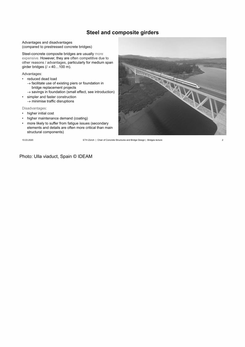
Photo: Ulla viaduct, Spain © IDEAM
2
Steel and composite girders
10.03.2020 2ETH Zürich | Chair of Concrete Structures and Bridge Design | Bridges lecture
Advantages and disadvantages(compared to prestressed concrete bridges)
Steel-concrete composite bridges are usually moreexpensive. However, they are often competitive due to other reasons / advantages, particularly for medium span girder bridges (l 40…100 m).
Advantages:• reduced dead load
facilitate use of existing piers or foundation inbridge replacement projectssavings in foundation (small effect, see introduction)
• simpler and faster constructionminimise traffic disruptions
Disadvantages:• higher initial cost• higher maintenance demand (coating)• more likely to suffer from fatigue issues (secondary
elements and details are often more critical than mainstructural components)
3
Superstructure / Girder bridges
10.03.2020 3
Design and erectionSteel and steel-concrete composite girders
Typical cross-sections and details
ETH Zürich | Chair of Concrete Structures and Bridge Design | Bridges lecture
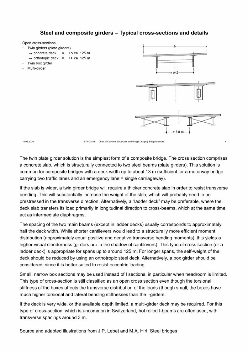
The twin plate girder solution is the simplest form of a composite bridge. The cross section comprises a concrete slab, which is structurally connected to two steel beams (plate girders). This solution is common for composite bridges with a deck width up to about 13 m (sufficient for a motorway bridge carrying two traffic lanes and an emergency lane = single carriageway).
If the slab is wider, a twin girder bridge will require a thicker concrete slab in order to resist transverse bending. This will substantially increase the weight of the slab, which will probably need to beprestressed in the transverse direction. Alternatively, a “ladder deck” may be preferable, where the deck slab transfers its load primarily in longitudinal direction to cross-beams, which at the same time act as intermediate diaphragms.
The spacing of the two main beams (except in ladder decks) usually corresponds to approximately half the deck width. While shorter cantilevers would lead to a structurally more efficient moment distribution (approximately equal positive and negative transverse bending moments), this yields a higher visual slenderness (girders are in the shadow of cantilevers). This type of cross section (or a ladder deck) is appropriate for spans up to around 125 m. For longer spans, the self-weight of the deck should be reduced by using an orthotropic steel deck. Alternatively, a box girder should beconsidered, since it is better suited to resist eccentric loading.
Small, narrow box sections may be used instead of I sections, in particular when headroom is limited. This type of cross-section is still classified as an open cross section even though the torsional stiffness of the boxes affects the transverse distribution of the loads (though small, the boxes have much higher torsional and lateral bending stiffnesses than the I-girders.
If the deck is very wide, or the available depth limited, a multi-girder deck may be required. For this type of cross-section, which is uncommon in Switzerland, hot rolled I-beams are often used, with transverse spacings around 3 m.
Source and adapted illustrations from J.P. Lebet and M.A. Hirt, Steel bridges
4
Steel and composite girders – Typical cross-sections and details
10.03.2020 4ETH Zürich | Chair of Concrete Structures and Bridge Design | Bridges lecture
Open cross-sections• Twin girders (plate girders)
concrete deck l ≤ ca. 125 morthotopic deck l > ca. 125 m
• Twin box girder• Multi-girder
2b
b
3.0 m
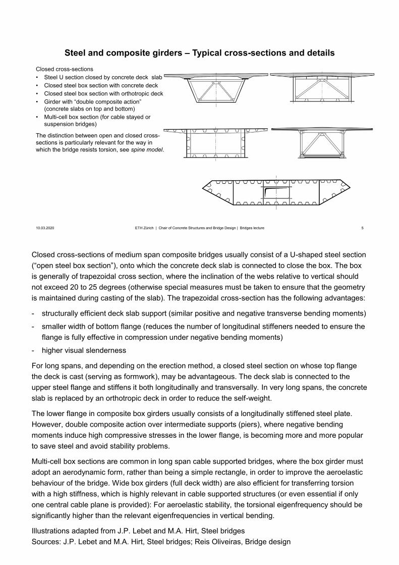
Closed cross-sections of medium span composite bridges usually consist of a U-shaped steel section (“open steel box section”), onto which the concrete deck slab is connected to close the box. The box is generally of trapezoidal cross section, where the inclination of the webs relative to vertical should not exceed 20 to 25 degrees (otherwise special measures must be taken to ensure that the geometry is maintained during casting of the slab). The trapezoidal cross-section has the following advantages:
- structurally efficient deck slab support (similar positive and negative transverse bending moments)
- smaller width of bottom flange (reduces the number of longitudinal stiffeners needed to ensure theflange is fully effective in compression under negative bending moments)
- higher visual slenderness
For long spans, and depending on the erection method, a closed steel section on whose top flange the deck is cast (serving as formwork), may be advantageous. The deck slab is connected to theupper steel flange and stiffens it both longitudinally and transversally. In very long spans, the concrete slab is replaced by an orthotropic deck in order to reduce the self-weight.
The lower flange in composite box girders usually consists of a longitudinally stiffened steel plate. However, double composite action over intermediate supports (piers), where negative bending moments induce high compressive stresses in the lower flange, is becoming more and more popular to save steel and avoid stability problems.
Multi-cell box sections are common in long span cable supported bridges, where the box girder must adopt an aerodynamic form, rather than being a simple rectangle, in order to improve the aeroelastic behaviour of the bridge. Wide box girders (full deck width) are also efficient for transferring torsion with a high stiffness, which is highly relevant in cable supported structures (or even essential if only one central cable plane is provided): For aeroelastic stability, the torsional eigenfrequency should be significantly higher than the relevant eigenfrequencies in vertical bending.
Illustrations adapted from J.P. Lebet and M.A. Hirt, Steel bridgesSources: J.P. Lebet and M.A. Hirt, Steel bridges; Reis Oliveiras, Bridge design
5
Steel and composite girders – Typical cross-sections and details
10.03.2020 5ETH Zürich | Chair of Concrete Structures and Bridge Design | Bridges lecture
Closed cross-sections• Steel U section closed by concrete deck slab• Closed steel box section with concrete deck• Closed steel box section with orthotropic deck• Girder with “double composite action”
(concrete slabs on top and bottom)• Multi-cell box section (for cable stayed or
suspension bridges)
The distinction between open and closed cross-sections is particularly relevant for the way in which the bridge resists torsion, see spine model.
Illustrations adapted from: left: J.P. Lebet and M.A. Hirt, Steel bridges; right: J. Manterora, Puentes I.
Photo: left: https://commons.wikimedia.org/; right: CFCSL https://www.cfcsl.com/
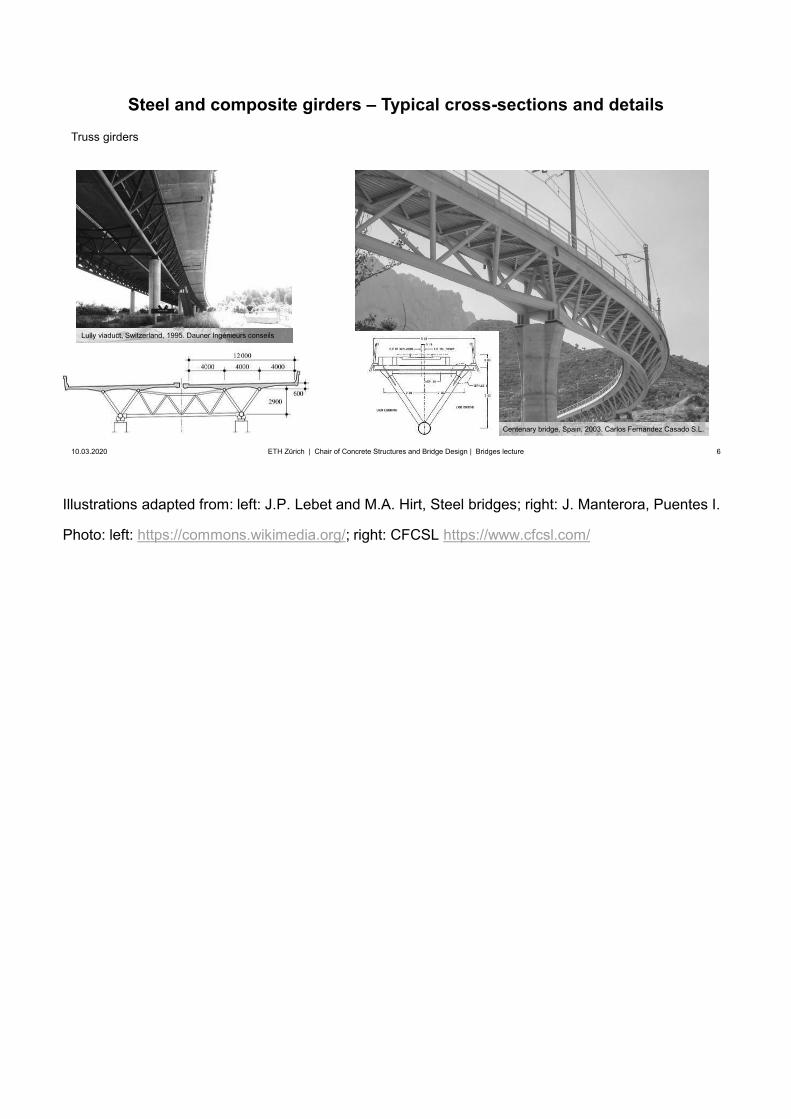
6
Steel and composite girders – Typical cross-sections and details
10.03.2020 6ETH Zürich | Chair of Concrete Structures and Bridge Design | Bridges lecture
Truss girders
Lully viaduct, Switzerland, 1995. Dauner Ingénieurs conseils
Centenary bridge, Spain, 2003. Carlos Fernandez Casado S.L.
Source: J.P. Lebet and M.A. Hirt, Steel bridges
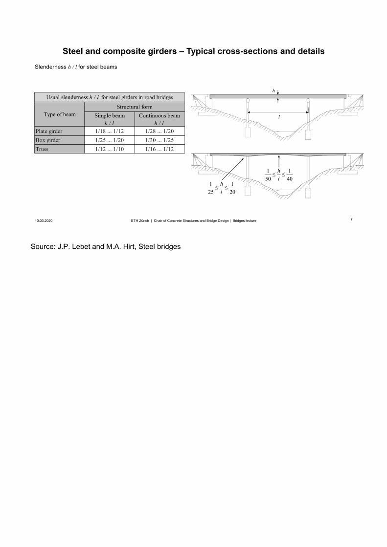
7
Steel and composite girders – Typical cross-sections and details
10.03.2020 7ETH Zürich | Chair of Concrete Structures and Bridge Design | Bridges lecture
Slenderness h / l for steel beams
l
h
1 125 20
hl
1 150 40
hl
Simple beamh / l
Continuous beamh / l
Plate girder 1/18 ... 1/12 1/28 ... 1/20Box girder 1/25 ... 1/20 1/30 ... 1/25Truss 1/12 ... 1/10 1/16 ... 1/12
Structural formType of beam
Usual slenderness h / l for steel girders in road bridges
Source: J.P. Lebet and M.A. Hirt, Steel bridges
Top photo: Plate girders, Viaduct over the Mularroya Dam, Spain © IDEAM
Bottom photo: Box girder, Highway A-357, Guadalhorce-Connection, Spain © IDEAM
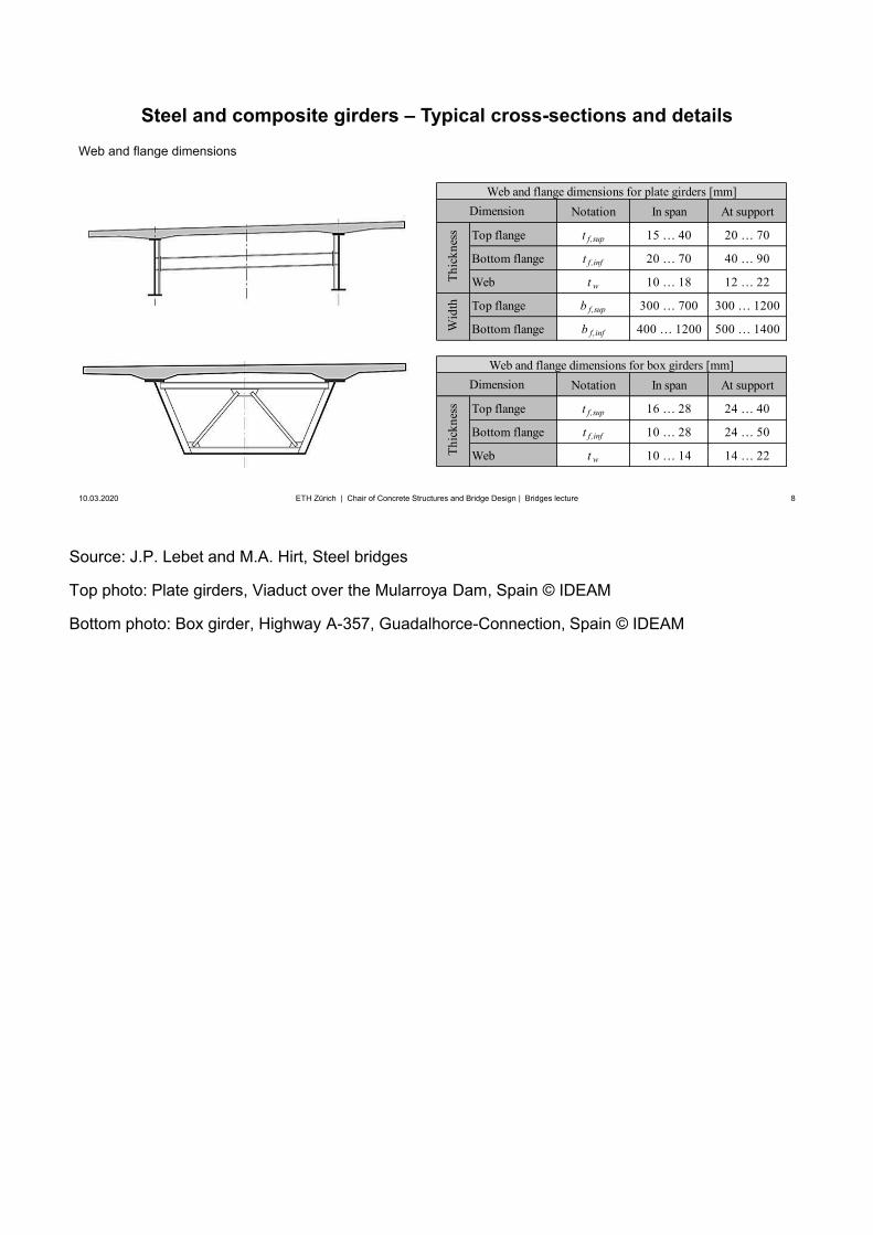
8
Steel and composite girders – Typical cross-sections and details
10.03.2020 8ETH Zürich | Chair of Concrete Structures and Bridge Design | Bridges lecture
Web and flange dimensions
Notation In span At support
Top flange t f,sup 15 … 40 20 … 70
Bottom flange t f,inf 20 … 70 40 … 90
Web t w 10 … 18 12 … 22
Top flange b f,sup 300 … 700 300 … 1200
Bottom flange b f,inf 400 … 1200 500 … 1400
Notation In span At support
Top flange t f,sup 16 … 28 24 … 40
Bottom flange t f,inf 10 … 28 24 … 50
Web t w 10 … 14 14 … 22
Dimension
Thic
knes
sW
idth
Thic
knes
s
Web and flange dimensions for plate girders [mm]Dimension
Web and flange dimensions for box girders [mm]
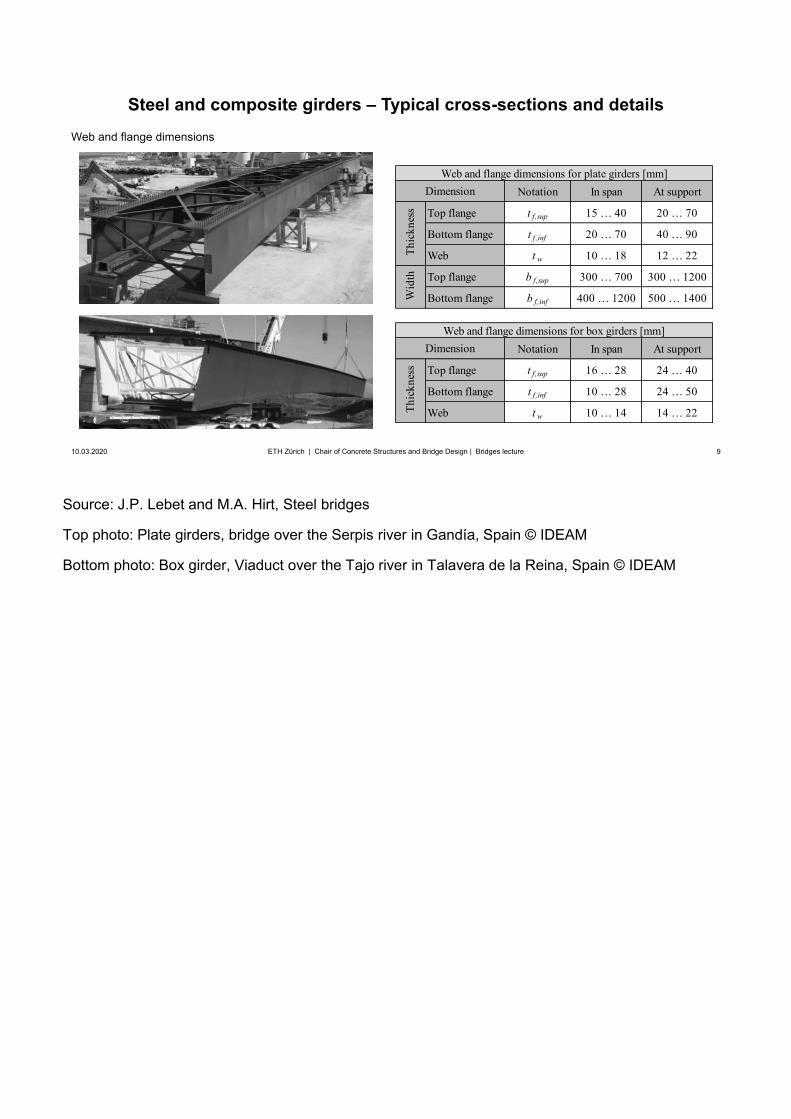
Source: J.P. Lebet and M.A. Hirt, Steel bridges
Top photo: Plate girders, bridge over the Serpis river in Gandía, Spain © IDEAM
Bottom photo: Box girder, Viaduct over the Tajo river in Talavera de la Reina, Spain © IDEAM
9
Notation In span At support
Top flange t f,sup 15 … 40 20 … 70
Bottom flange t f,inf 20 … 70 40 … 90
Web t w 10 … 18 12 … 22
Top flange b f,sup 300 … 700 300 … 1200
Bottom flange b f,inf 400 … 1200 500 … 1400
Notation In span At support
Top flange t f,sup 16 … 28 24 … 40
Bottom flange t f,inf 10 … 28 24 … 50
Web t w 10 … 14 14 … 22
Dimension
Thic
knes
sW
idth
Thic
knes
s
Web and flange dimensions for plate girders [mm]Dimension
Web and flange dimensions for box girders [mm]
Steel and composite girders – Typical cross-sections and details
10.03.2020 9ETH Zürich | Chair of Concrete Structures and Bridge Design | Bridges lecture
Web and flange dimensions

10
Superstructure / Girder bridges
10.03.2020 10
Design and erectionSteel and steel-concrete composite girders
Structural analysis and design – General remarks
ETH Zürich | Chair of Concrete Structures and Bridge Design | Bridges lecture
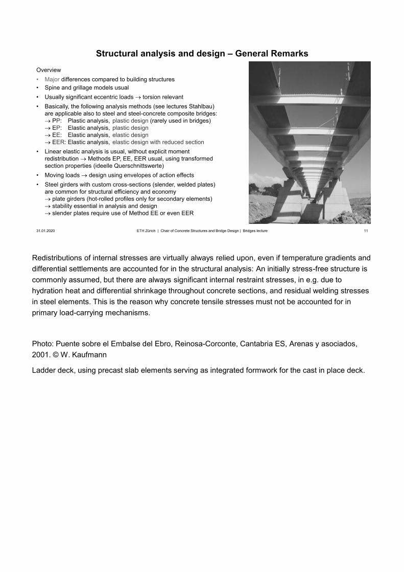
Redistributions of internal stresses are virtually always relied upon, even if temperature gradients and differential settlements are accounted for in the structural analysis: An initially stress-free structure is commonly assumed, but there are always significant internal restraint stresses, in e.g. due to hydration heat and differential shrinkage throughout concrete sections, and residual welding stresses in steel elements. This is the reason why concrete tensile stresses must not be accounted for in primary load-carrying mechanisms.
Photo: Puente sobre el Embalse del Ebro, Reinosa-Corconte, Cantabria ES, Arenas y asociados,2001. © W. Kaufmann
Ladder deck, using precast slab elements serving as integrated formwork for the cast in place deck.
11
Structural analysis and design – General Remarks
31.01.2020 11ETH Zürich | Chair of Concrete Structures and Bridge Design | Bridges lecture
Overview• Major differences compared to building structures• Spine and grillage models usual• Usually significant eccentric loads torsion relevant• Basically, the following analysis methods (see lectures Stahlbau)
are applicable also to steel and steel-concrete composite bridges:PP: Plastic analysis, plastic design (rarely used in bridges)EP: Elastic analysis, plastic designEE: Elastic analysis, elastic designEER: Elastic analysis, elastic design with reduced section
• Linear elastic analysis is usual, without explicit momentredistribution Methods EP, EE, EER usual, using transformedsection properties (ideelle Querschnittswerte)
• Moving loads design using envelopes of action effects• Steel girders with custom cross-sections (slender, welded plates)
are common for structural efficiency and economyplate girders (hot-rolled profiles only for secondary elements)stability essential in analysis and designslender plates require use of Method EE or even EER
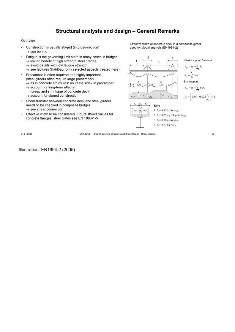
Illustration: EN1994-2 (2005)
12
Structural analysis and design – General Remarks
31.01.2020 12ETH Zürich | Chair of Concrete Structures and Bridge Design | Bridges lecture
Overview
• Construction is usually staged (in cross-section)see behind
• Fatigue is the governing limit state in many cases in bridgeslimited benefit of high strength steel gradesavoid details with low fatigue strengthsee lectures Stahlbau (only selected aspects treated here)
• Precamber is often required and highly important(steel girders often require large precamber)
as in concrete structures: no «safe side» in precamberaccount for long-term effects(creep and shrinkage of concrete deck)account for staged construction
• Shear transfer between concrete deck and steel girdersneeds to be checked in composite bridges
see shear connection• Effective width to be considered. Figure shows values for
concrete flanges, steel plates see EN 1993-1-5
Effective width of concrete deck in a composite girderused for global analysis (EN1994-2)
2
01
2
01
8
0.55 0.025 1
eff eii
eei i
eff i eii
ei
ei
b b b
Lb b
b b b
Lb
Interior support / midspan:
End support:
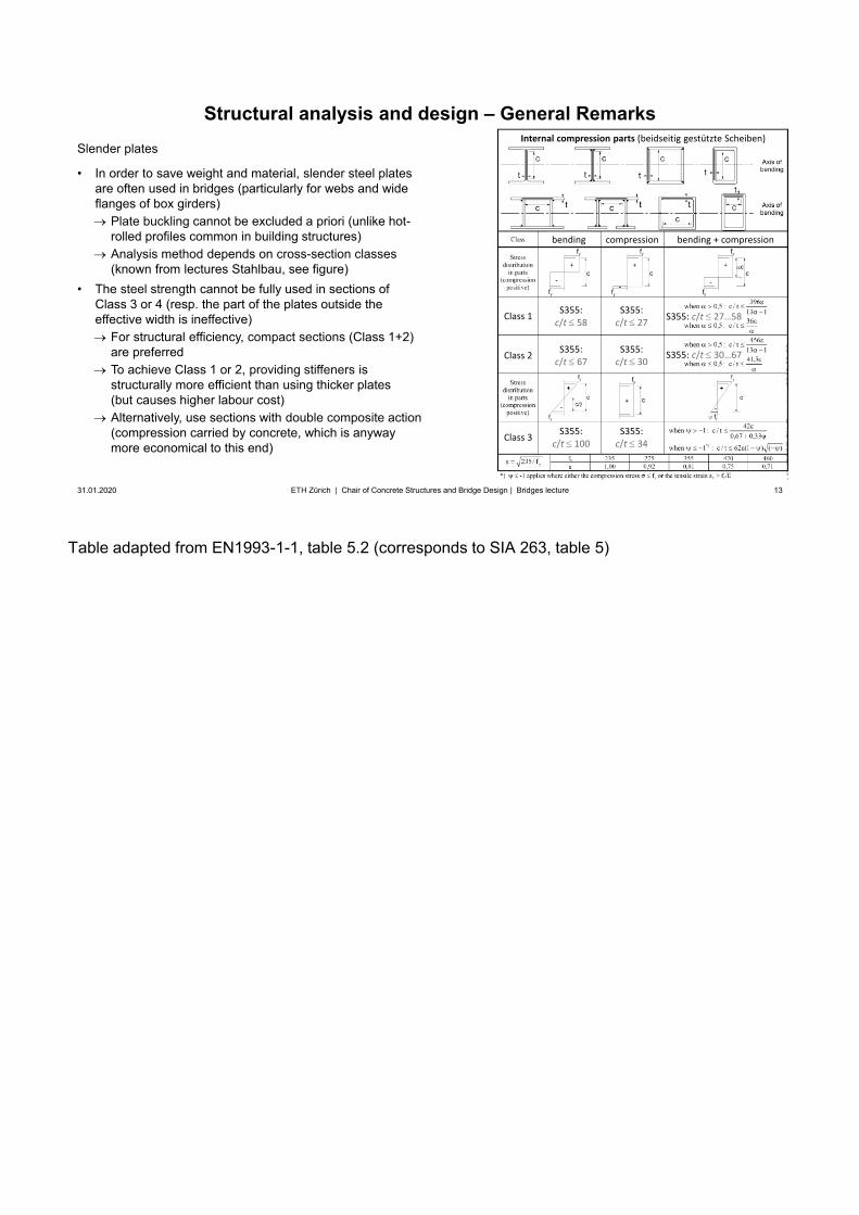
Table adapted from EN1993-1-1, table 5.2 (corresponds to SIA 263, table 5)
13
Structural analysis and design – General Remarks
31.01.2020 13ETH Zürich | Chair of Concrete Structures and Bridge Design | Bridges lecture
Slender plates
• In order to save weight and material, slender steel platesare often used in bridges (particularly for webs and wideflanges of box girders)
Plate buckling cannot be excluded a priori (unlike hot-rolled profiles common in building structures)Analysis method depends on cross-section classes(known from lectures Stahlbau, see figure)
• The steel strength cannot be fully used in sections ofClass 3 or 4 (resp. the part of the plates outside theeffective width is ineffective)
For structural efficiency, compact sections (Class 1+2)are preferredTo achieve Class 1 or 2, providing stiffeners isstructurally more efficient than using thicker plates(but causes higher labour cost)Alternatively, use sections with double composite action(compression carried by concrete, which is anyway more economical to this end)
Class 1 S355:c/t 58
S355:c/t 27
S355:c/t 67
S355:c/t 30Class 2
S355:c/t 100
S355:c/t 34Class 3
bending compression bending + compression
S355: c/t 27…58
Internal compression parts (beidseitig gestützte Scheiben)
S355: c/t 30…67
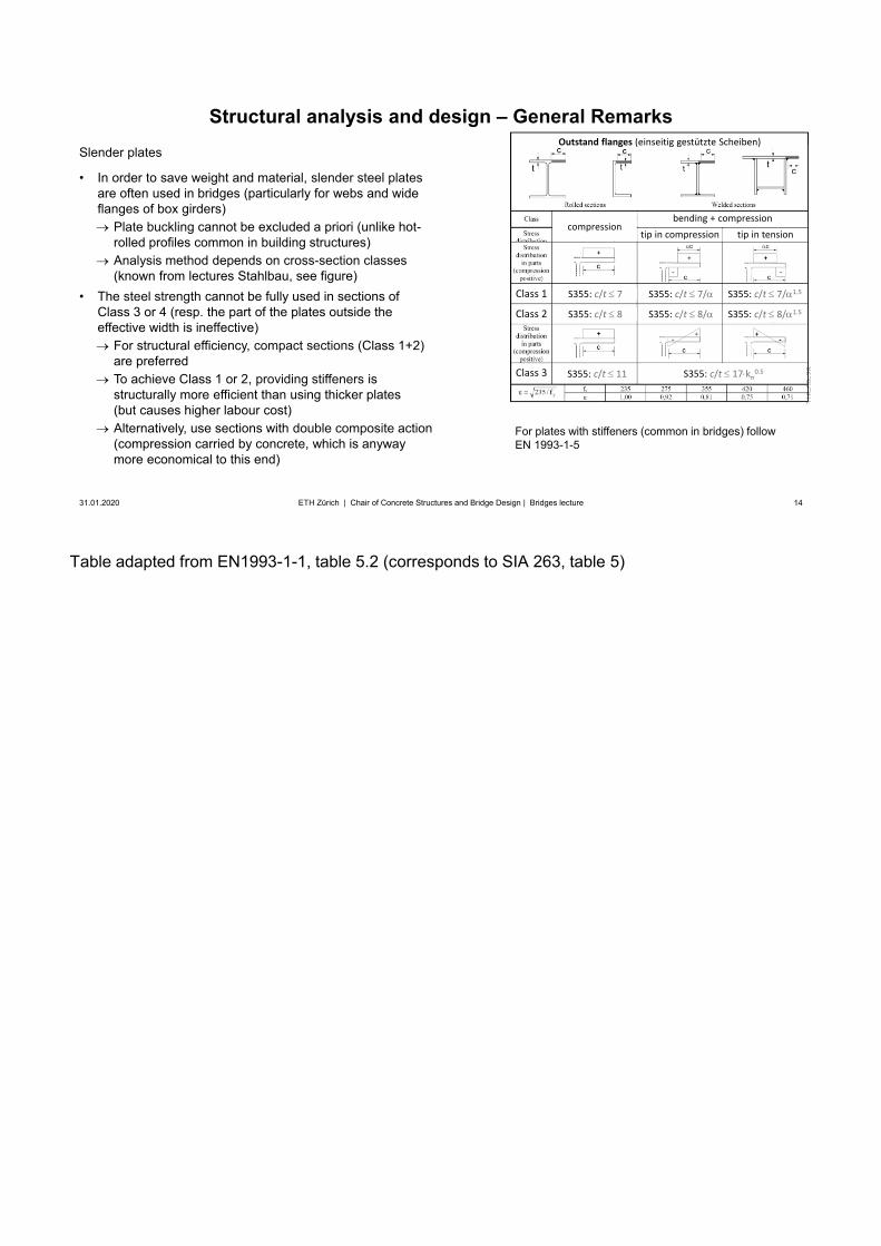
Table adapted from EN1993-1-1, table 5.2 (corresponds to SIA 263, table 5)
14
Structural analysis and design – General Remarks
31.01.2020 14ETH Zürich | Chair of Concrete Structures and Bridge Design | Bridges lecture
Slender plates
• In order to save weight and material, slender steel platesare often used in bridges (particularly for webs and wideflanges of box girders)
Plate buckling cannot be excluded a priori (unlike hot-rolled profiles common in building structures)Analysis method depends on cross-section classes(known from lectures Stahlbau, see figure)
• The steel strength cannot be fully used in sections ofClass 3 or 4 (resp. the part of the plates outside theeffective width is ineffective)
For structural efficiency, compact sections (Class 1+2)are preferredTo achieve Class 1 or 2, providing stiffeners isstructurally more efficient than using thicker plates(but causes higher labour cost)Alternatively, use sections with double composite action(compression carried by concrete, which is anyway more economical to this end)
compressionbending + compression
Outstand flanges (einseitig gestützte Scheiben)
tip in compression tip in tension
Class 1
Class 2
Class 3
S355: c/t 7
S355: c/t 8
S355: c/t 7/
S355: c/t 8/
S355: c/t 7/ 1.5
S355: c/t 8/ 1.5
S355: c/t 11 S355: c/t 17 k 0.5
For plates with stiffeners (common in bridges) follow EN 1993-1-5
Illustrations: Lebet and Hirt, Steel Structures
15
Structural analysis and design – General Remarks
10.03.2020 15ETH Zürich | Chair of Concrete Structures and Bridge Design | Bridges lecture
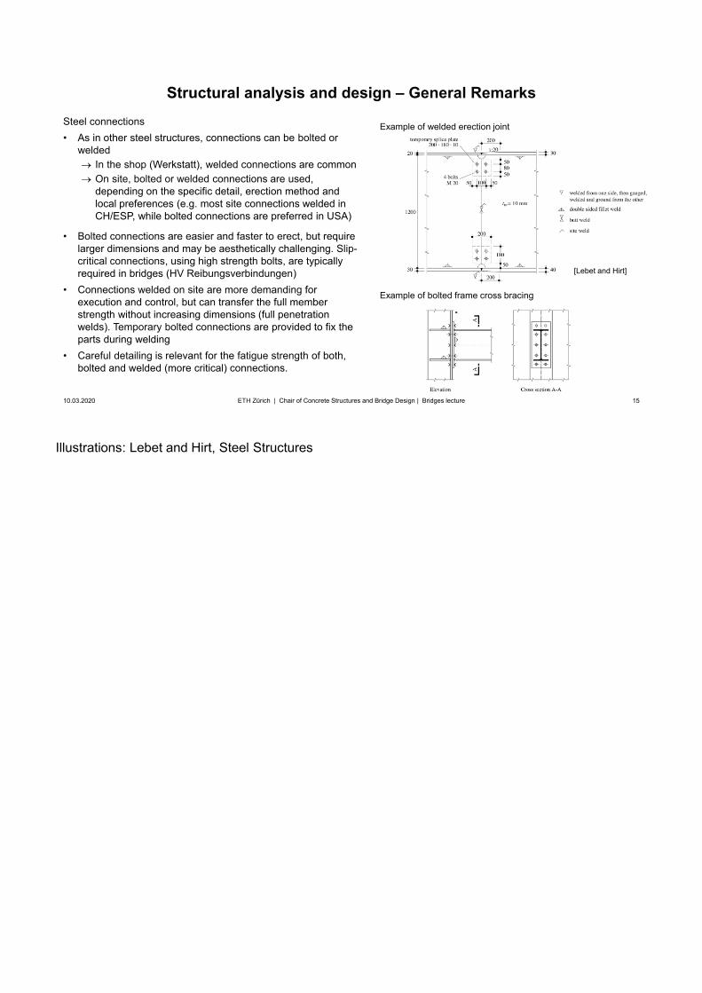
Steel connections• As in other steel structures, connections can be bolted or
weldedIn the shop (Werkstatt), welded connections are commonOn site, bolted or welded connections are used,depending on the specific detail, erection method and local preferences (e.g. most site connections welded in CH/ESP, while bolted connections are preferred in USA)
• Bolted connections are easier and faster to erect, but requirelarger dimensions and may be aesthetically challenging. Slip-critical connections, using high strength bolts, are typicallyrequired in bridges (HV Reibungsverbindungen)
• Connections welded on site are more demanding forexecution and control, but can transfer the full memberstrength without increasing dimensions (full penetrationwelds). Temporary bolted connections are provided to fix theparts during welding
• Careful detailing is relevant for the fatigue strength of both,bolted and welded (more critical) connections.
Example of welded erection joint
[Lebet and Hirt]
Example of bolted frame cross bracing
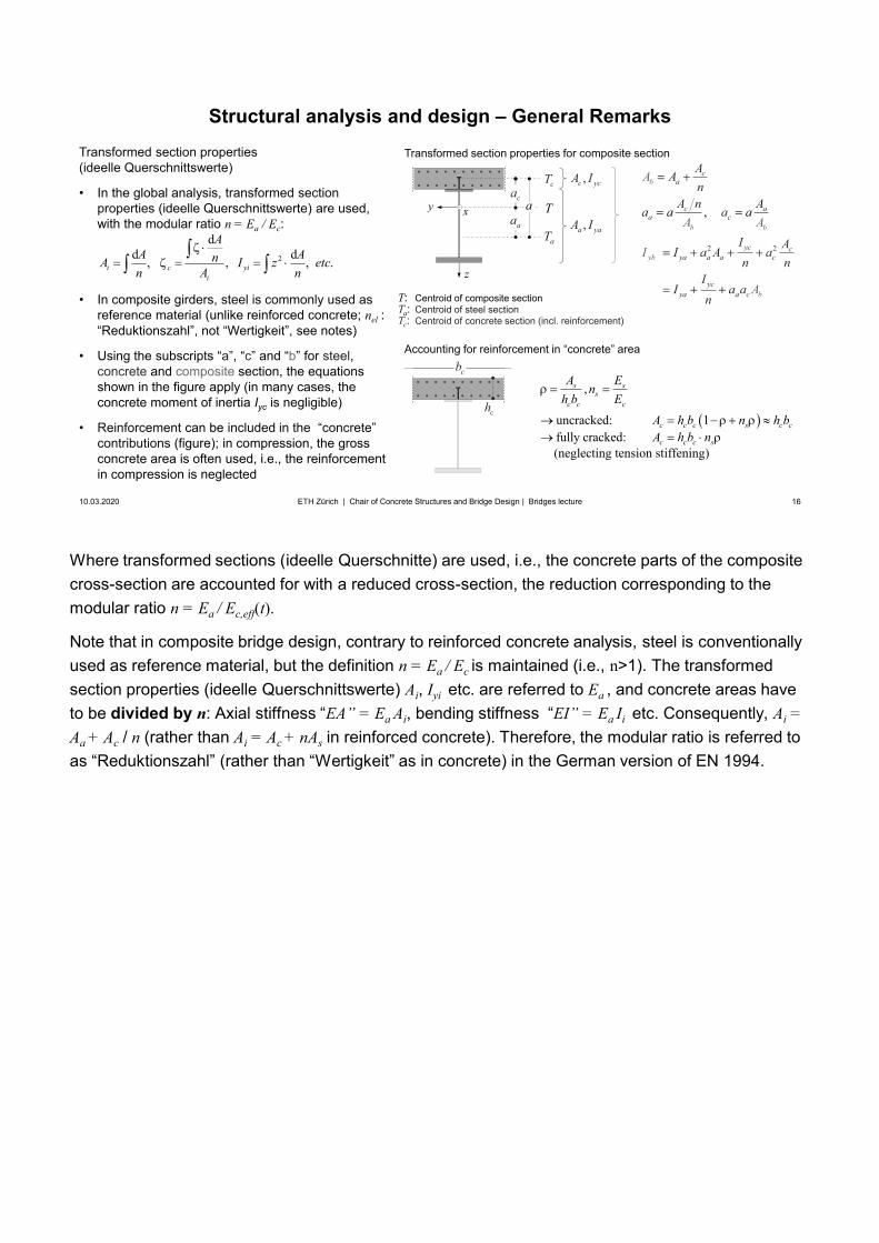
Where transformed sections (ideelle Querschnitte) are used, i.e., the concrete parts of the composite cross-section are accounted for with a reduced cross-section, the reduction corresponding to the modular ratio n = Ea / Ec,eff(t).
Note that in composite bridge design, contrary to reinforced concrete analysis, steel is conventionally used as reference material, but the definition n = Ea / Ec is maintained (i.e., n>1). The transformed section properties (ideelle Querschnittswerte) Ai, Iyi etc. are referred to Ea , and concrete areas have to be divided by n: Axial stiffness “EA” = Ea Ai, bending stiffness “EI” = Ea Ii etc. Consequently, Ai =Aa + Ac / n (rather than Ai = Ac + nAs in reinforced concrete). Therefore, the modular ratio is referred to as “Reduktionszahl” (rather than “Wertigkeit” as in concrete) in the German version of EN 1994.
16
Structural analysis and design – General Remarks
10.03.2020 16ETH Zürich | Chair of Concrete Structures and Bridge Design | Bridges lecture
Transformed section properties (ideelle Querschnittswerte)
• In the global analysis, transformed sectionproperties (ideelle Querschnittswerte) are used,with the modular ratio n = Ea / Ec:
• In composite girders, steel is commonly used asreference material (unlike reinforced concrete; nel :“Reduktionszahl”, not “Wertigkeit”, see notes)
• Using the subscripts “a”, “c” and “b” for steel,concrete and composite section, the equationsshown in the figure apply (in many cases, theconcrete moment of inertia Iyc is negligible)
• Reinforcement can be included in the “concrete”contributions (figure); in compression, the grossconcrete area is often used, i.e., the reinforcementin compression is neglected
2
dd d, , , .i c yi
i
AA AnA I z etcn A n z
xy
aT
cT
T
Transformed section properties for composite section
T: Centroid of composite sectionTa: Centroid of steel sectionTc: Centroid of concrete section (incl. reinforcement)
22
,
c
cc
ycb
b
a
aa
ya a a
y
b
b
a
cc
ycc
b
a
y
A
a
An
A n a
I Aa
A
Aa
I a An n
II
aA A
an
a
I
A
,c ycA I
,a yaA I
ca
aaa
ch
cb
,
uncracked: 1fully cracked:
(neglecting tension stiffening)
s ss
c c c
c c c s c c
c c c s
A Enh b E
A h b n h bA h b n
Accounting for reinforcement in “concrete” area
For non-standard cases (e.g. double composite action), more refined approaches (see e.g. Advanced Structural Concrete, Trost’s Method) may be used.
17
Structural analysis and design – General Remarks
10.03.2020 17ETH Zürich | Chair of Concrete Structures and Bridge Design | Bridges lecture
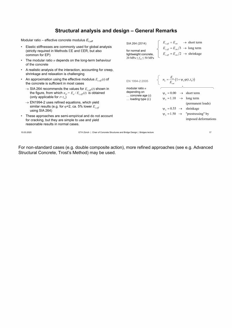
Modular ratio – effective concrete modulus Ec,eff
• Elastic stiffnesses are commonly used for global analysis(strictly required in Methods EE and EER, but alsocommon for EP)
• The modular ratio n depends on the long-term behaviourof the concrete
• A realistic analysis of the interaction, accounting for creep,shrinkage and relaxation is challenging
• An approximation using the effective modulus Ec,eff (t) ofthe concrete is sufficient in most cases
SIA 264 recommends the values for Ec,eff (t) shown inthe figure, from which nel = Ea / Ec,eff (t) is obtained(only applicable for t=t )EN1994-2 uses refined equations, which yield similar results (e.g. for =2, ca. 5% lower Ec,effusing SIA 264)
• These approaches are semi-empirical and do not accountfor cracking, but they are simple to use and yieldreasonable results in normal cases.
,
,
,
short term
3 long term
2 shrinkage
c eff cm
c eff cm
c eff cm
E E
E E
E E
01 ( , )aL L
cm
En t tE
0.00 short term1.10 long term
(permanent loads)0.55 shrinkage1.50 "prestressing" by
imposed deformations
L
L
L
L
SIA 264 (2014)
for normal and lightweight concrete, 20 MPa ≤ fck ≤ 50 MPa
EN 1994-2:2005
modular ratio ndepending on… concrete age (t)… loading type (L)
1) Here and in the following, the abbreviations for limit states of Eurocodes are used:
- ULS STR = structural safety, limit state type 2 according to SIA 260(reaching of the ultimate resistance of the structure or one of its structural members, i.e., failuredue to rupture, excessive deformations, the structure forming a mechanism, or loss of stability ofone or multiple structural members)
- ULS FAT = structural safety, limit state type 4 according to SIA 260(reaching the fatigue resistance of the structure or one of its structural members)
Note that “ULS” is sometimes used as synonym for ULS STR, and FAT for ULS FAT although “ULS” may refer to EQU, STR, GEO and FAT limit states (structural safety limit states type 1-4 according to SIA 260)2) For a strictly elastic verification, all actions must be considered to obtain the stress distributions,including differential settlements, thermal gradients etc. Furthermore, the designation “EE” must notbe misunderstood in the sense, that the entire cross-section needs to remain elastic in ULS. Rather,inelastic tensile strains are allowed in cross-sectional analysis (to determine e.g. the bendingresistance) when using Method EE with cross-section Class 3.
3) According to EN 1993-1-5: 2006 (General rules - Plated structural elements), the effect of platebuckling on the stiffness may be ignored if the effective cross-sectional area (over which the full yieldstress is assumed) of an element in compression is larger than ρlim times the gross cross-sectionalarea of the same element. The parameter ρlim may be specified in the National Annexes (ρlim = 0,5 isrecommended, and the Swiss NA adopts does not change this default value).
For structural efficiency, plates should be stiffened such that the effective cross-sectional area is not severely reduced. Hence, the full cross-section may be used when determining internal actions forsuch plates. An exception are webs of plate girders, whose effective width in bending (longitudinal compression on compressed side of web) is often significantly reduced. Since the webs contribute very little to the bending stiffness, using the full cross-section in structural analysis is still commonpractice in these cases.
18
Structural analysis and design – General Remarks
10.03.2020 18ETH Zürich | Chair of Concrete Structures and Bridge Design | Bridges lecture
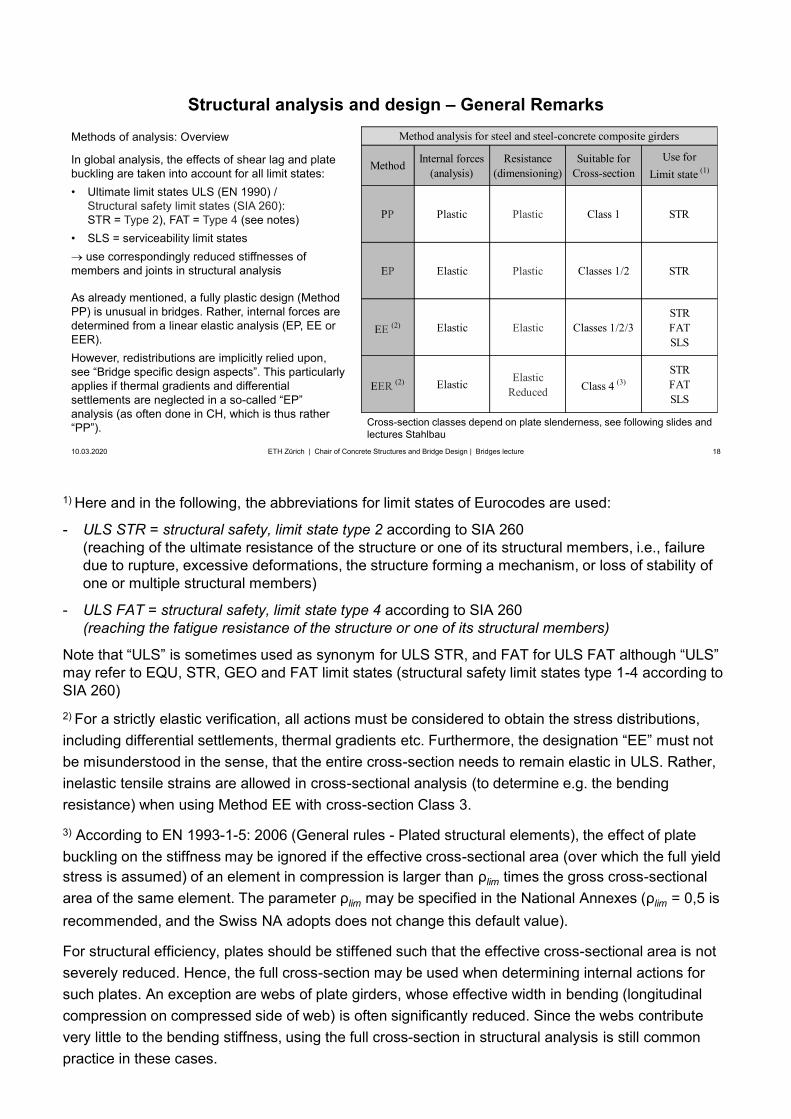
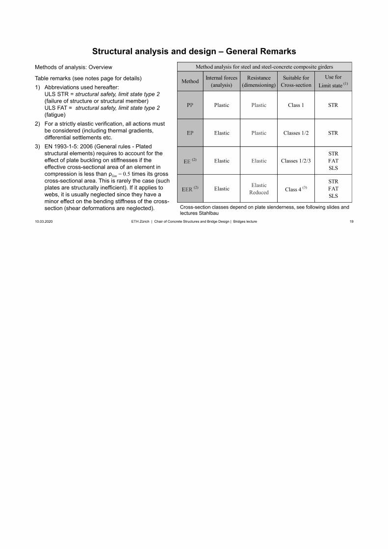
Methods of analysis: Overview
In global analysis, the effects of shear lag and plate buckling are taken into account for all limit states:• Ultimate limit states ULS (EN 1990) /
Structural safety limit states (SIA 260):STR = Type 2), FAT = Type 4 (see notes)
• SLS = serviceability limit statesuse correspondingly reduced stiffnesses of
members and joints in structural analysis
As already mentioned, a fully plastic design (Method PP) is unusual in bridges. Rather, internal forces are determined from a linear elastic analysis (EP, EE orEER).However, redistributions are implicitly relied upon,see “Bridge specific design aspects”. This particularly applies if thermal gradients and differential settlements are neglected in a so-called “EP” analysis (as often done in CH, which is thus rather “PP”).
Method Internal forces(analysis)
Resistance(dimensioning)
Suitable forCross-section
Use for Limit state (1)
PP Plastic Plastic Class 1 STR
EP Elastic Plastic Classes 1/2 STR
EE (2) Elastic Elastic Classes 1/2/3STR FATSLS
EER (2) Elastic ElasticReduced Class 4 (3)
STR FATSLS
Method analysis for steel and steel-concrete composite girders
Cross-section classes depend on plate slenderness, see following slides andlectures Stahlbau
19
Structural analysis and design – General Remarks
10.03.2020 19ETH Zürich | Chair of Concrete Structures and Bridge Design | Bridges lecture
Methods of analysis: Overview
Table remarks (see notes page for details)1) Abbreviations used hereafter:
ULS STR = structural safety, limit state type 2(failure of structure or structural member)ULS FAT = structural safety, limit state type 2(fatigue)
2) For a strictly elastic verification, all actions mustbe considered (including thermal gradients,differential settlements etc.
3) EN 1993-1-5: 2006 (General rules - Platedstructural elements) requires to account for theeffect of plate buckling on stiffnesses if theeffective cross-sectional area of an element incompression is less than ρlim = 0.5 times its grosscross-sectional area. This is rarely the case (suchplates are structurally inefficient). If it applies towebs, it is usually neglected since they have aminor effect on the bending stiffness of the cross-section (shear deformations are neglected). Cross-section classes depend on plate slenderness, see following slides and
lectures Stahlbau
Method Internal forces(analysis)
Resistance(dimensioning)
Suitable forCross-section
Use for Limit state (1)
PP Plastic Plastic Class 1 STR
EP Elastic Plastic Classes 1/2 STR
EE (2) Elastic Elastic Classes 1/2/3STR FATSLS
EER (2) Elastic ElasticReduced Class 4 (3)
STR FATSLS
Method analysis for steel and steel-concrete composite girders
20
Structural analysis and design – General Remarks
10.03.2020 20ETH Zürich | Chair of Concrete Structures and Bridge Design | Bridges lecture
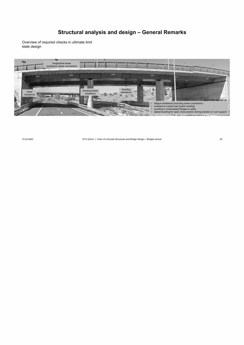
Overview of required checks in ultimate limit state design
shearresistance
bendingresistancebending-shear
resistance
longitudinal shearresistance (shear connection)
• fatigue resistance (including shear connection)• resistance to point load (patch loading)• buckling in compressed flanges or webs• lateral buckling for open cross-section during erection or over support
21
Superstructure / Girder bridges
10.03.2020 21
Design and erectionSteel and steel-concrete composite girders
Structural analysis and design – Staged construction
ETH Zürich | Chair of Concrete Structures and Bridge Design | Bridges lecture
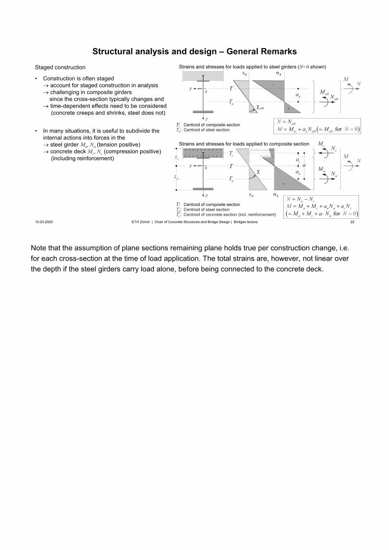
Note that the assumption of plane sections remaining plane holds true per construction change, i.e. for each cross-section at the time of load application. The total strains are, however, not linear over the depth if the steel girders carry load alone, before being connected to the concrete deck.
22
z
xy
Structural analysis and design – General Remarks
10.03.2020 22ETH Zürich | Chair of Concrete Structures and Bridge Design | Bridges lecture
Staged construction
• Construction is often stagedaccount for staged construction in analysischallenging in composite girderssince the cross-section typically changes andtime-dependent effects need to be considered(concrete creeps and shrinks, steel does not)
• In many situations, it is useful to subdivide theinternal actions into forces in the
steel girder Ma, Na (tension positive)concrete deck Mc, Nc (compression positive)(including reinforcement)
0aM
x
aT
z
xyaM
cM
aN
cNM
N
aT
cT
Tca
aaa
x
cz
az
Strains and stresses for loads applied to steel girders (N=0 shown)
Strains and stresses for loads applied to composite section
aaT
0
, 0 0 f 0or a
a a a a
N NM a N NMM
0a
0for
c
c c
a
a a
a
ca
a c
NM a N
N NM a N
M NM
NaMT: Centroid of composite sectionTa: Centroid of steel sectionTc: Centroid of concrete section (incl. reinforcement)
xx
T: Centroid of composite sectionTa: Centroid of steel section
MN
0aN
For steel-concrete composite bridges, the self-weight of the slab usually acts on the steel structure alone (unless the deck is cast in-situ on a formwork supported continuously by falsework on the ground, which is rarely the case). Hence:
• The steel girders alone carry their self weight and the weight of the concrete during casting
• The steel-concrete composite girders resist all loads applied after hardening of the concrete ( =establishing the longitudinal shear connection between steel and concrete)
The actions are thus applied to a static system with different cross-section. The analysis is further complicated since:
• Additional, temporary supports to the steel girders are often provided during casting of the deck
• The concrete deck is often cast in stages (typically midspan sections first, pier sections last)
• The concrete deck usually cracks over the piers, shrinks and creeps under sustained loads
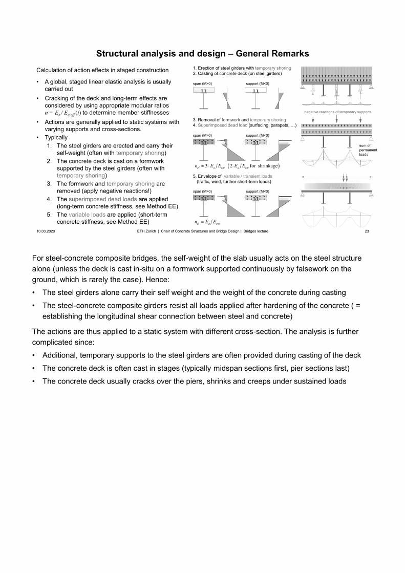
23
Structural analysis and design – General Remarks
10.03.2020 23
Calculation of action effects in staged construction
• A global, staged linear elastic analysis is usuallycarried out
• Cracking of the deck and long-term effects areconsidered by using appropriate modular ratiosn = Es / Ec,eff (t) to determine member stiffnesses
• Actions are generally applied to static systems withvarying supports and cross-sections.
• Typically1. The steel girders are erected and carry their
self-weight (often with temporary shoring)2. The concrete deck is cast on a formwork
supported by the steel girders (often withtemporary shoring)
3. The formwork and temporary shoring areremoved (apply negative reactions!)
4. The superimposed dead loads are applied(long-term concrete stiffness, see Method EE)
5. The variable loads are applied (short-termconcrete stiffness, see Method EE)
ETH Zürich | Chair of Concrete Structures and Bridge Design | Bridges lecture
1. Erection of steel girders with temporary shoring2. Casting of concrete deck (on steel girders)
3. Removal of formwork and temporary shoring4. Superimposed dead load (surfacing, parapets, …)
5. Envelope of variable / transient loads (traffic, wind, further short-term loads)
3 2 for shrinkageel a cm a cmn E E E E
el a cmn E E
span (M>0) support (M<0)
span (M>0) support (M<0)
span (M>0) support (M<0)
sum ofpermanent loads
negative reactions of temporary supports
24
Structural analysis and design – General Remarks
10.03.2020 24
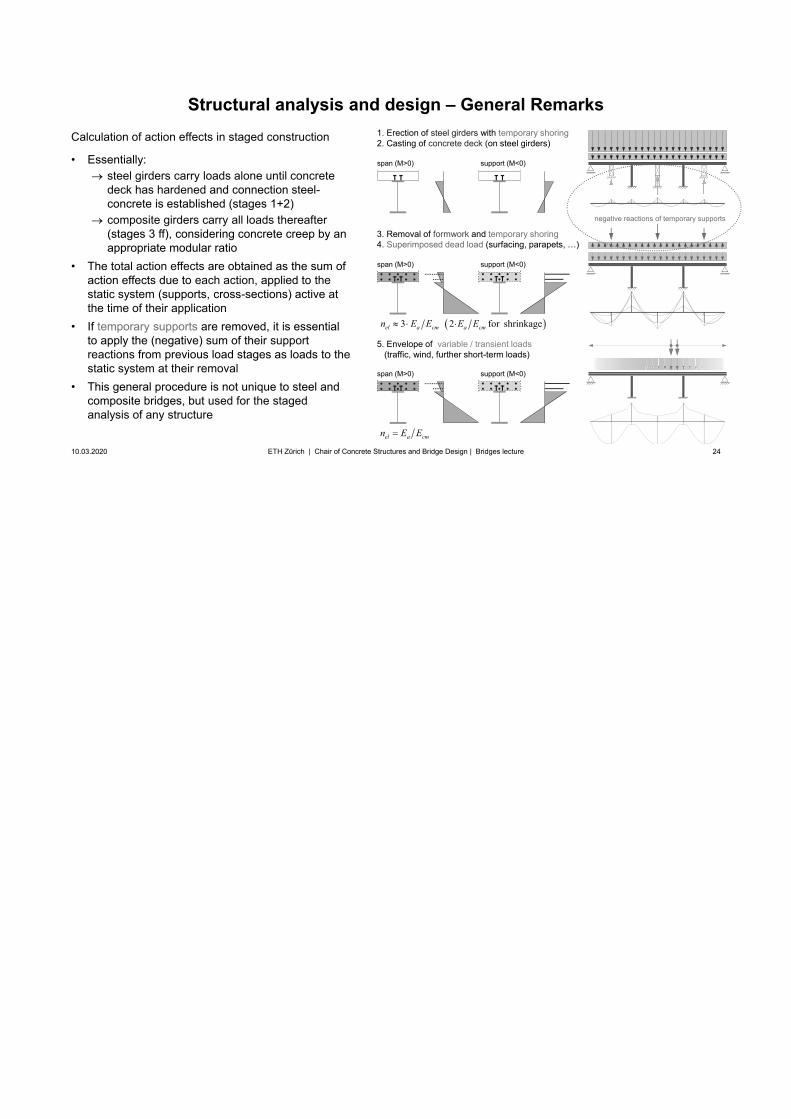
Calculation of action effects in staged construction
• Essentially:steel girders carry loads alone until concretedeck has hardened and connection steel-concrete is established (stages 1+2)composite girders carry all loads thereafter(stages 3 ff), considering concrete creep by an appropriate modular ratio
• The total action effects are obtained as the sum ofaction effects due to each action, applied to thestatic system (supports, cross-sections) active atthe time of their application
• If temporary supports are removed, it is essentialto apply the (negative) sum of their support reactions from previous load stages as loads to the static system at their removal
• This general procedure is not unique to steel andcomposite bridges, but used for the stagedanalysis of any structure
ETH Zürich | Chair of Concrete Structures and Bridge Design | Bridges lecture
1. Erection of steel girders with temporary shoring2. Casting of concrete deck (on steel girders)
3. Removal of formwork and temporary shoring4. Superimposed dead load (surfacing, parapets, …)
5. Envelope of variable / transient loads (traffic, wind, further short-term loads)
3 2 for shrinkageel a cm a cmn E E E E
el a cmn E E
span (M>0) support (M<0)
span (M>0) support (M<0)
span (M>0) support (M<0)
negative reactions of temporary supports
25
Superstructure / Girder bridges
10.03.2020 25
Design and erectionSteel and steel-concrete composite girders
Structural analysis and design – Elastic-plastic design (EP)
ETH Zürich | Chair of Concrete Structures and Bridge Design | Bridges lecture
Here and in the following slides, the factored action effects are designated by subscript “Ed” (EC) rather than simply “d” as in SIA codes.
26
Structural analysis and design – Elastic-plastic design (EP)
10.03.2020 26
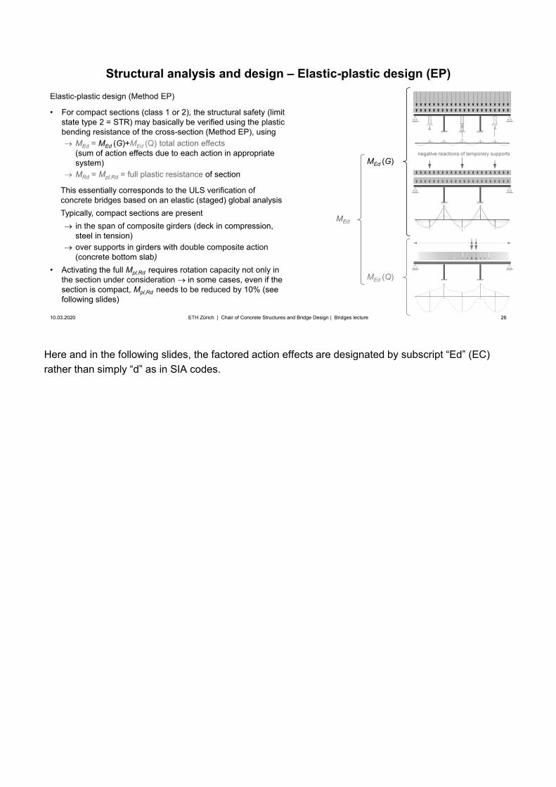
Elastic-plastic design (Method EP)
• For compact sections (class 1 or 2), the structural safety (limitstate type 2 = STR) may basically be verified using the plasticbending resistance of the cross-section (Method EP), using
MEd = MEd (G)+MEd (Q) total action effects(sum of action effects due to each action in appropriate system)MRd = Mpl,Rd = full plastic resistance of section
This essentially corresponds to the ULS verification of concrete bridges based on an elastic (staged) global analysisTypically, compact sections are present
in the span of composite girders (deck in compression, steel in tension)over supports in girders with double composite action (concrete bottom slab)
• Activating the full Mpl,Rd requires rotation capacity not only inthe section under consideration in some cases, even if thesection is compact, Mpl,Rd needs to be reduced by 10% (seefollowing slides)
ETH Zürich | Chair of Concrete Structures and Bridge Design | Bridges lecture
negative reactions of temporary supportsMEd (G)
MEd (Q)
MEd
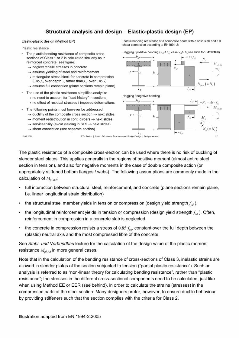
The plastic resistance of a composite cross-section can be used where there is no risk of buckling of slender steel plates. This applies generally in the regions of positive moment (almost entire steel section in tension), and also for negative moments in the case of double composite action (or appropriately stiffened bottom flanges / webs). The following assumptions are commonly made in the calculation of Mpl,Rd:
• full interaction between structural steel, reinforcement, and concrete (plane sections remain plane,i.e. linear longitudinal strain distribution)
• the structural steel member yields in tension or compression (design yield strength fyd ).
• the longitudinal reinforcement yields in tension or compression (design yield strength fsd ). Often,reinforcement in compression in a concrete slab is neglected.
• the concrete in compression resists a stress of 0.85·fcd, constant over the full depth between the(plastic) neutral axis and the most compressed fibre of the concrete.
See Stahl- und Verbundbau lecture for the calculation of the design value of the plastic moment resistance Mpl,Rd in more general cases.
Note that in the calculation of the bending resistance of cross-sections of Class 3, inelastic strains are allowed in slender plates of the section subjected to tension (“partial plastic resistance”). Such an analysis is referred to as “non-linear theory for calculating bending resistance”, rather than “plastic resistance”; the stresses in the different cross-sectional components need to be calculated, just like when using Method EE or EER (see behind), in order to calculate the strains (stresses) in the compressed parts of the steel section. Many designers prefer, however, to ensure ductile behaviour by providing stiffeners such that the section complies with the criteria for Class 2.
Illustration adapted from EN 1994-2:2005
27
Structural analysis and design – Elastic-plastic design (EP)
10.03.2020 27ETH Zürich | Chair of Concrete Structures and Bridge Design | Bridges lecture
Plastic bending resistance of a composite beam with a solid slab and full shear connection according to EN1994-2:
Sagging / positive bending (xpl < hc; case xpl > hc see slide for S420/460)
z
xy
0.85 cdf
,pl RdM
effb
h
ydf
cN
plx
, cpl aN N
z
xy
,pl RdM
effb
h
ydf
ydf
caN N
aM
Elastic-plastic design (Method EP)
Plastic resistance• The plastic bending resistance of composite cross-
sections of Class 1 or 2 is calculated similarly as inreinforced concrete (see figure)
neglect tensile stresses in concreteassume yielding of steel and reinforcementrectangular stress block for concrete in compression(0.85 fcd over depth x, rather than fcd over 0.85 x)assume full connection (plane sections remain plane)
• The use of the plastic resistance simplifies analysis:no need to account for “load history” in sectionsno effect of residual stresses / imposed deformations
• The following points must however be addressed:ductility of the composite cross section next slidesmoment redistribution in cont. girders next slidesserviceability (avoid yielding in SLS next slides)shear connection (see separate section)
sdfc sdN As f
Hogging / negative bending
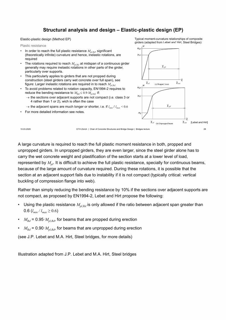
A large curvature is required to reach the full plastic moment resistance in both, propped and unpropped girders. In unpropped girders, they are even larger, since the steel girder alone has to carry the wet concrete weight and plastification of the section starts at a lower level of load, represented by Mpl. It is difficult to achieve the full plastic resistance, specially for continuous beams, because of the large amount of curvature required. During these rotations, it is possible that the section at an adjacent support fails due to instability if it is not compact (typically critical: vertical buckling of compression flange into web).
Rather than simply reducing the bending resistance by 10% if the sections over adjacent supports are not compact, as proposed by EN1994-2, Lebet and Hirt propose the following:
• Using the plastic resistance Mpl,Rd is only allowed if the ratio between adjacent span greater than0.6 (lmin / lmax ≥ 0.6)
• MRd = 0.95·Mpl,Rd, for beams that are propped during erection
• MRd = 0.90·Mpl,Rd, for beams that are unpropped during erection
(see J.P. Lebet and M.A. Hirt, Steel bridges, for more details)
Illustration adapted from J.P. Lebet and M.A. Hirt, Steel bridges
28
Structural analysis and design – Elastic-plastic design (EP)
10.03.2020 28ETH Zürich | Chair of Concrete Structures and Bridge Design | Bridges lecture
Elastic-plastic design (Method EP)
Plastic resistance• In order to reach the full plastic resistance Mpl,Rd, significant
(theoretically infinite) curvature and hence, inelastic rotations, arerequired
• The rotations required to reach Mpl,Rd at midspan of a continuous girdergenerally may require inelastic rotations in other parts of the girder,particularly over supports.
• This particularly applies to girders that are not propped duringconstruction (steel girders carry wet concrete over full span), seefigure: Larger inelastic rotations are required in to reach Mpl,Rd
• To avoid problems related to rotation capacity, EN1994-2 requires toreduce the bending resistance to MRd 0.9 Mpl,Rd if:
the sections over adjacent supports are not compact (i.e. class 3 or4 rather than 1 or 2), wich is often the casethe adjacent spans are much longer or shorter, i.e. if lmin / lmax < 0.6
• For more detailed information see notes.
Typical moment-curvature relationships of composite girders (adapted from Lebet and Hirt, Steel Bridges):girders (adapted from Lebet and Hirt, S
tot
totel
el
pl
pl
[Lebet and Hirt]
Note that the reduction for high-strength steel is likely to be overly conservative, and will probably bechanged in the upcoming revision of EN1994.
Illustrations adapted from EN 1994-2:2005
29
Structural analysis and design – Elastic-plastic design (EP)
10.03.2020 29ETH Zürich | Chair of Concrete Structures and Bridge Design | Bridges lecture
Elastic-plastic design (Method EP)
Plastic resistance• Apart from rotation capacity, the shear connection also
needs to be designed to enable the utilisation of Mpl,Rdsee the corresponding section
• Plastic design may lead to situations where inelasticstrains occur under service conditions. This could occurparticularly in unpropped girders, but should be avoided
check stresses (as outlined in section on Method EE) inservice conditions (characteristic combination) to makesure the section remains elastic, i.e., MEd,SLS≤ Mel,Rd
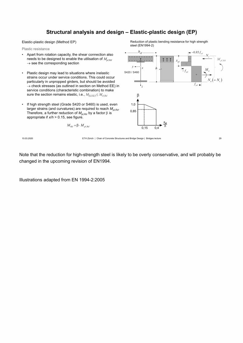
• If high strength steel (Grade S420 or S460) is used, evenlarger strains (and curvatures) are required to reach Mpl,Rd.Therefore, a further reduction of Mpl,Rd by a factor isappropriate if x/h > 0.15, see figure.
Reduction of plastic bending resistance for high strength steel (EN1994-2)
z
xy
0.85 cdf
,pl RdM
hydf
ydf
cN
plx
caN N
aMS420 / S460
effb
,Rd pl RdM M
30
Superstructure / Girder bridges
10.03.2020 30
Design and erectionSteel and steel-concrete composite girders
Structural analysis and design – Elastic design (EE, EER)
ETH Zürich | Chair of Concrete Structures and Bridge Design | Bridges lecture
31
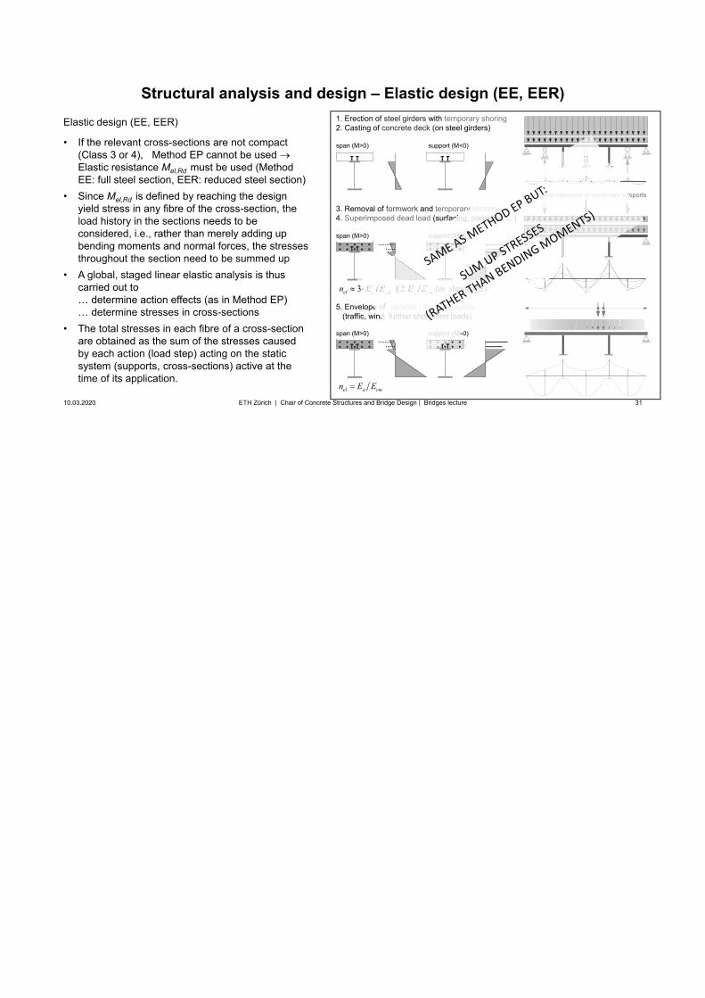
3 2 for shrinkageel a cm a cmn E E E E
Structural analysis and design – Elastic design (EE, EER)
10.03.2020 31
Elastic design (EE, EER)
• If the relevant cross-sections are not compact(Class 3 or 4), Method EP cannot be used Elastic resistance Mel,Rd must be used (MethodEE: full steel section, EER: reduced steel section)
• Since Mel,Rd is defined by reaching the designyield stress in any fibre of the cross-section, theload history in the sections needs to beconsidered, i.e., rather than merely adding upbending moments and normal forces, the stressesthroughout the section need to be summed up
• A global, staged linear elastic analysis is thuscarried out to… determine action effects (as in Method EP)… determine stresses in cross-sections
• The total stresses in each fibre of a cross-sectionare obtained as the sum of the stresses causedby each action (load step) acting on the staticsystem (supports, cross-sections) active at thetime of its application.
ETH Zürich | Chair of Concrete Structures and Bridge Design | Bridges lecture
1. Erection of steel girders with temporary shoring2. Casting of concrete deck (on steel girders)
3. Removal of formwork and temporary shoring4. Superimposed dead load (surfacing, parapets, …)
5. Envelope of variable / transient loads (traffic, wind, further short-term loads)
el a cmn E E
span (M>0) support (M<0)
span (M>0) support (M<0)
span (M>0) support (M<0)
negative reactions of temporary supports
2 for shrinkagea cm a cm2222222222
ary shoringfacing, parapets, g …)
pe of variable / transient loads nd, further short-term loads)
support (M<0)t (M<0)
support (M<0
negative reactions of temporary sup
Here and in the following slides, the factored action effects are designated by subscript “Ed” (EC) rather than simply “d” as in SIA codes.
32
Structural analysis and design – Elastic design (EE, EER)
10.03.2020 32
Elastic design (EE, EER)
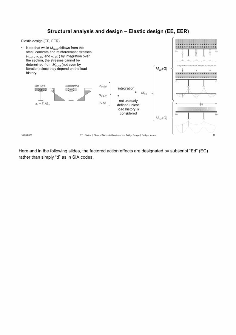
• Note that while Mel,Rd follows from thesteel, concrete and reinforcement stresses( a,Ed, c,Ed and s,Ed ) by integration overthe section, the stresses cannot bedetermined from Mel,Rd (not even byiteration) since they depend on the loadhistory.
ETH Zürich | Chair of Concrete Structures and Bridge Design | Bridges lecture
negative reactions of temporary supportsMEd (G)
MEd (Q)
MEd
a,Ed
c,Ed
s,Edel a cmn E E
span (M>0) support (M<0)integration
not uniquelydefined unlessload history is
considered
The difference in the position of the centroid for short-term and long-term loads (different effective modulus of concrete, centroid lower for long-term loads) has been neglected for simplification. Figure adapted from Lebet and Hirt, Steel bridges.
33
z
xy
Structural analysis and design – Elastic design (EE, EER)
10.03.2020 33ETH Zürich | Chair of Concrete Structures and Bridge Design | Bridges lecture
z
xy
aT
T
(a) Stresses – girder unpropped during construction
(b) Stresses – girder totally propped during construction
self-weight(steel+concrete)
steel alone
permanentloads
transientloads
total stresses
self-weight(steel+concrete)composite girder
permanentloads
transientloads
total stresses
,0.85 ck
Ed cc
f
,y
Ed ay
f
,y
Ed ay
f
,y
Ed ay
f
,y
Ed ay
f
,0.85 ck
Ed cc
f
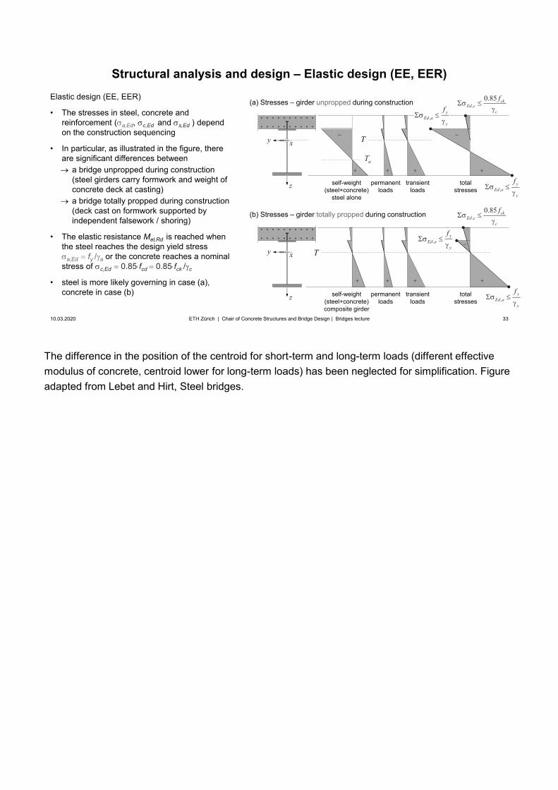
Elastic design (EE, EER)
• The stresses in steel, concrete andreinforcement ( a,Ed, c,Ed and s,Ed ) dependon the construction sequencing
• In particular, as illustrated in the figure, thereare significant differences between
a bridge unpropped during construction(steel girders carry formwork and weight of concrete deck at casting)a bridge totally propped during construction (deck cast on formwork supported by independent falsework / shoring)
• The elastic resistance Mel,Rd is reached whenthe steel reaches the design yield stress
a,Ed fy / a or the concrete reaches a nominalstress of c,Ed 0.85 fcd 0.85 fck / c
• steel is more likely governing in case (a),concrete in case (b)
T
34
Structural analysis and design – Elastic design (EE, EER)
10.03.2020 34ETH Zürich | Chair of Concrete Structures and Bridge Design | Bridges lecture
Elastic design (EE, EER)
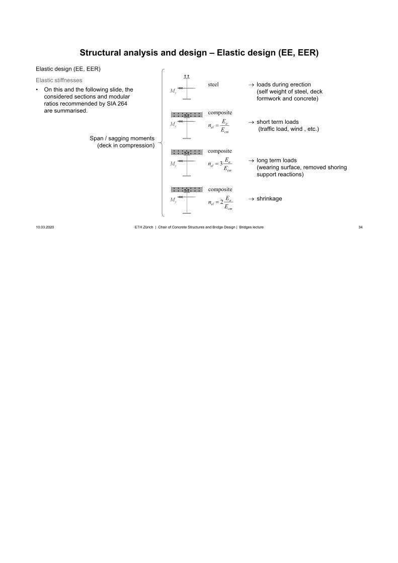
Elastic stiffnesses• On this and the following slide, the
considered sections and modularratios recommended by SIA 264are summarised. composite
ael
cm
EnE
steel
composite
3 ael
cm
EnE
composite
2 ael
cm
EnE
loads during erection (self weight of steel, deck formwork and concrete)
long term loads(wearing surface, removed shoring support reactions)
shrinkage
short term loads(traffic load, wind , etc.)
Span / sagging moments(deck in compression)
My
My
My
My
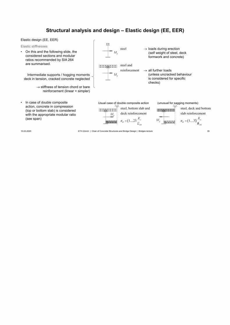
35
Structural analysis and design – Elastic design (EE, EER)
10.03.2020 35ETH Zürich | Chair of Concrete Structures and Bridge Design | Bridges lecture
Elastic design (EE, EER)
Elastic stiffnesses• On this and the following slide, the
considered sections and modularratios recommended by SIA 264are summarised.
• In case of double compositeaction, concrete in compression(top or bottom slab) is consideredwith the appropriate modular ratio(see span)
steel andreinforcement
steel loads during erection (self weight of steel, deck formwork and concrete)
all further loads(unless uncracked behaviour is considered for specific checks)
Intermediate supports / hogging momentsdeck in tension, cracked concrete neglected
stiffness of tension chord or bare reinforcement (linear = simpler)
steel, bottom slab anddeck reinforcement
1 3 ael
cm
EnE
aa
My
My
steel, deck and bottomslab reinforcement
1 3 ael
cm
EnE
aa
Usual case of double composite action (unusual for sagging moments)
My
My
36
Superstructure / Girder bridges
10.03.2020 36
Design and erectionSteel and steel-concrete composite girdersStructural analysis and design – Fatigue
ETH Zürich | Chair of Concrete Structures and Bridge Design | Bridges lecture
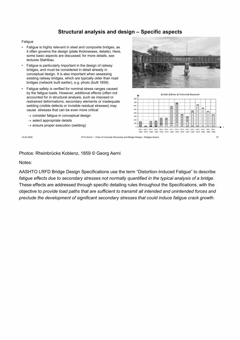
Photos: Rheinbrücke Koblenz, 1859 © Georg Aerni
Notes:
AASHTO LRFD Bridge Design Specifications use the term “Distortion-Induced Fatigue” to describefatigue effects due to secondary stresses not normally quantified in the typical analysis of a bridge.These effects are addressed through specific detailing rules throughout the Specifications, with the objective to provide load paths that are sufficient to transmit all intended and unintended forces and preclude the development of significant secondary stresses that could induce fatigue crack growth.
37
Structural analysis and design – Specific aspects
10.03.2020 37ETH Zürich | Chair of Concrete Structures and Bridge Design | Bridges lecture
Fatigue• Fatigue is highly relevant in steel and composite bridges, as
it often governs the design (plate thicknesses, details). Here,some basic aspects are discussed; for more details, seelectures Stahlbau
• Fatigue is particularly important in the design of railwaybridges, and must be considered in detail already inconceptual design. It is also important when assessingexisting railway bridges, which are typically older than roadbridges (network built earlier), e.g. photo (built 1859)
• Fatigue safety is verified for nominal stress ranges causedby the fatigue loads. However, additional effects (often notaccounted for in structural analysis, such as imposed orrestrained deformations, secondary elements or inadequatewelding (visible defects or invisible residual stresses) maycause stresses that can be even more critical
consider fatigue in conceptual designselect appropriate detailsensure proper execution (welding)
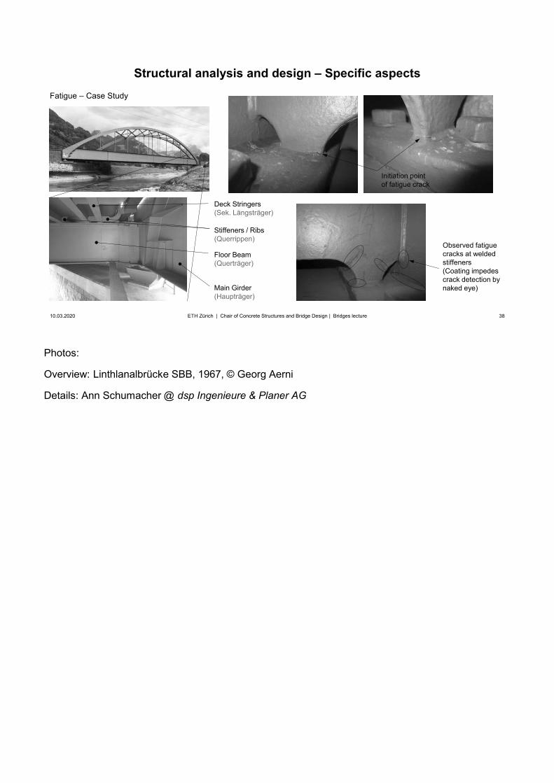
Photos:
Overview: Linthlanalbrücke SBB, 1967, © Georg Aerni
Details: Ann Schumacher @ dsp Ingenieure & Planer AG
38
Structural analysis and design – Specific aspects
10.03.2020 38ETH Zürich | Chair of Concrete Structures and Bridge Design | Bridges lecture
Fatigue – Case Study
Main Girder(Haupträger)
Floor Beam(Querträger)
Deck Stringers(Sek. Längsträger)
Stiffeners / Ribs(Querrippen)
Observed fatigue cracks at welded stiffeners(Coating impedes crack detection by naked eye)
Initiation point of fatigue crack
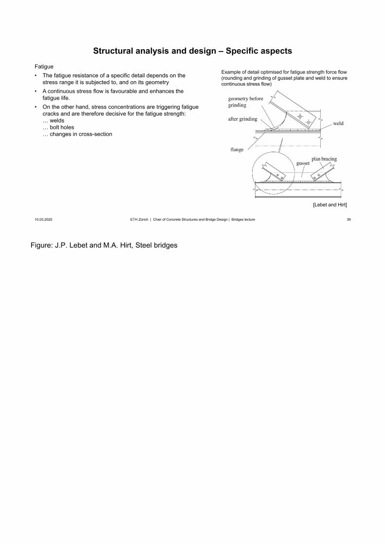
Figure: J.P. Lebet and M.A. Hirt, Steel bridges
39
Structural analysis and design – Specific aspects
10.03.2020 39ETH Zürich | Chair of Concrete Structures and Bridge Design | Bridges lecture
Fatigue• The fatigue resistance of a specific detail depends on the
stress range it is subjected to, and on its geometry• A continuous stress flow is favourable and enhances the
fatigue life.• On the other hand, stress concentrations are triggering fatigue
cracks and are therefore decisive for the fatigue strength:… welds… bolt holes… changes in cross-section
Example of detail optimised for fatigue strength force flow(rounding and grinding of gusset plate and weld to ensure continuous stress flow)
[Lebet and Hirt]
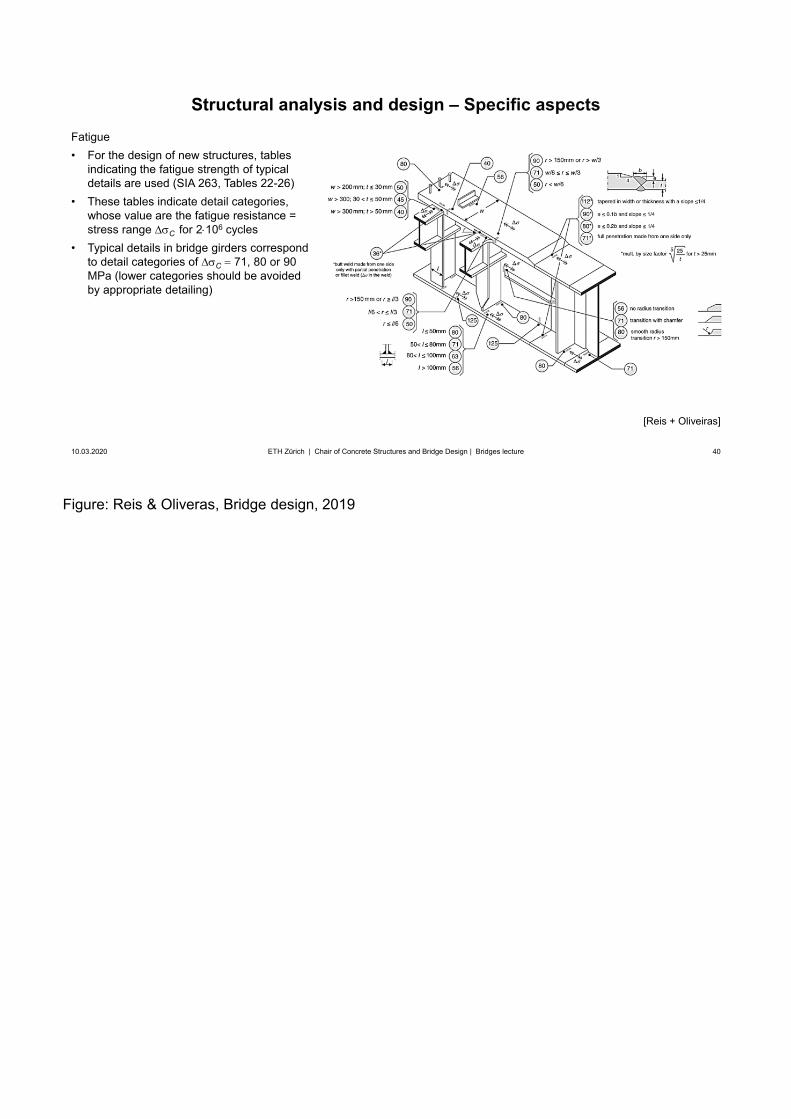
Figure: Reis & Oliveras, Bridge design, 2019
40
Structural analysis and design – Specific aspects
10.03.2020 40ETH Zürich | Chair of Concrete Structures and Bridge Design | Bridges lecture
Fatigue• For the design of new structures, tables
indicating the fatigue strength of typicaldetails are used (SIA 263, Tables 22-26)
• These tables indicate detail categories,whose value are the fatigue resistance =stress range C for 2 106 cycles
• Typical details in bridge girders correspondto detail categories of C 71, 80 or 90MPa (lower categories should be avoidedby appropriate detailing)
[Reis + Oliveiras]
41
Structural analysis and design – Specific aspects
10.03.2020 41ETH Zürich | Chair of Concrete Structures and Bridge Design | Bridges lecture
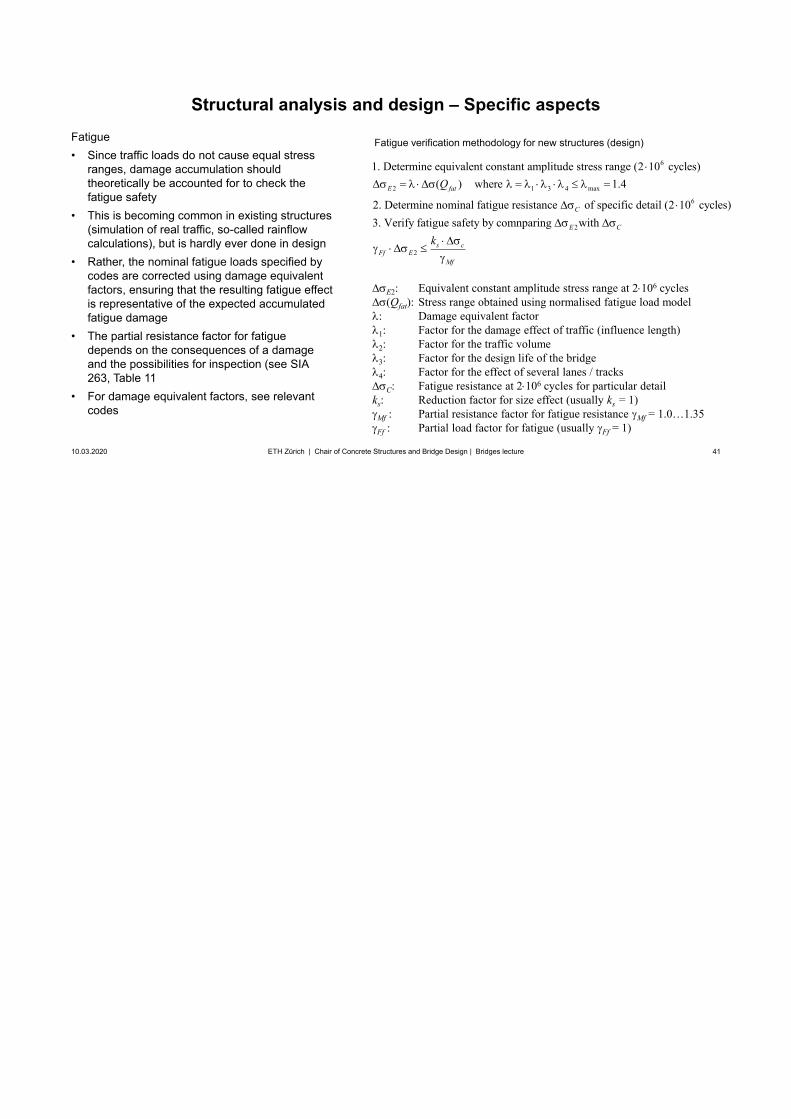
Fatigue • Since traffic loads do not cause equal stress
ranges, damage accumulation shouldtheoretically be accounted for to check thefatigue safety
• This is becoming common in existing structures(simulation of real traffic, so-called rainflowcalculations), but is hardly ever done in design
• Rather, the nominal fatigue loads specified bycodes are corrected using damage equivalentfactors, ensuring that the resulting fatigue effectis representative of the expected accumulatedfatigue damage
• The partial resistance factor for fatiguedepends on the consequences of a damageand the possibilities for inspection (see SIA263, Table 11
• For damage equivalent factors, see relevantcodes
E2: Equivalent constant amplitude stress range at 2 106 cycles(Qfat): Stress range obtained using normalised fatigue load model
: Damage equivalent factor1: Factor for the damage effect of traffic (influence length)2: Factor for the traffic volume3: Factor for the design life of the bridge4: Factor for the effect of several lanes / tracks
C: Fatigue resistance at 2 106 cycles for particular detailks: Reduction factor for size effect (usually ks = 1)
Mf : Partial resistance factor for fatigue resistance Mf = 1.0…1.35Ff : Partial load factor for fatigue (usually Ff = 1)
6
2 1 3 4 max
6
1. Determine equivalent constant amplitude stress range (2 10 cycles)( ) where 1.4
2. Determine nominal fatigue resistance of specific detail (2 10 cycles)3. Verify fati
E fat
C
Q
2
2
gue safety by comnparing with E C
s cFf E
Mf
k
Fatigue verification methodology for new structures (design)
42
Superstructure / Girder bridges
10.03.2020 42
Design and erectionSteel and steel-concrete composite girders
Structural analysis and design – Shear Connection
ETH Zürich | Chair of Concrete Structures and Bridge Design | Bridges lecture
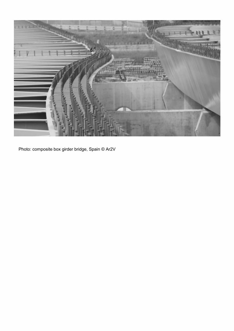
Photo: composite box girder bridge, Spain © Ar2V
43
10.03.2020 43ETH Zürich | Chair of Concrete Structures and Bridge Design | Bridges lecture
44
Structural analysis and design – Shear Connection
10.03.2020 44ETH Zürich | Chair of Concrete Structures and Bridge Design | Bridges lecture
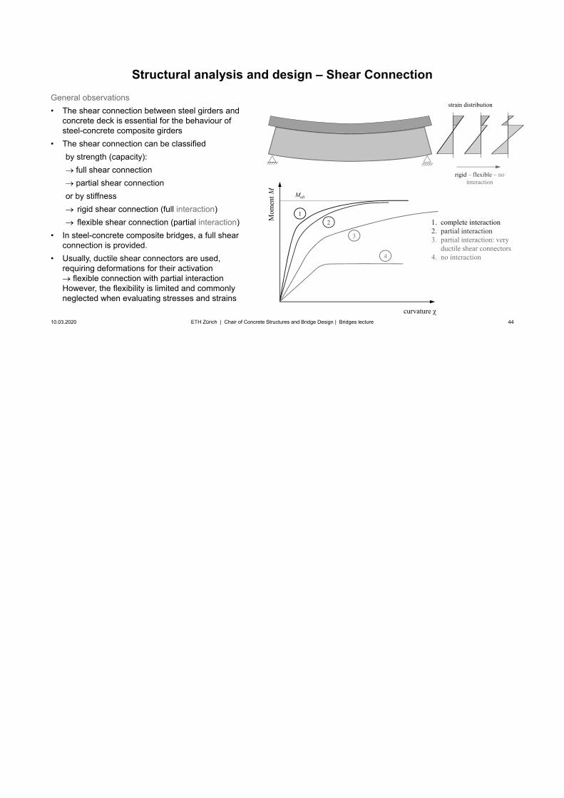
General observations• The shear connection between steel girders and
concrete deck is essential for the behaviour ofsteel-concrete composite girders
• The shear connection can be classifiedby strength (capacity):
full shear connectionpartial shear connection
or by stiffnessrigid shear connection (full interaction)flexible shear connection (partial interaction)
• In steel-concrete composite bridges, a full shearconnection is provided.
• Usually, ductile shear connectors are used,requiring deformations for their activation
flexible connection with partial interactionHowever, the flexibility is limited and commonlyneglected when evaluating stresses and strains
rigid – flexible – nointeraction
curvature
Mom
ent M Mult
12
3
4
1. complete interaction2. partial interaction3. partial interaction: very
ductile shear connectors4. no interaction
strain distribution
45
Structural analysis and design – Shear Connection
10.03.2020 45ETH Zürich | Chair of Concrete Structures and Bridge Design | Bridges lecture
inf
inf
s
inf
( ) ( ) d d ( ) ( )d 0
d ( )( ) ( ) ( )dd
dM dMd, d
(
d d
( ) ( )d ( )( ))
z
xz s s xzs
zx
xz s sz
y y yx zx z
y
y
y
z sxz
y
z
s
ssz s
z b z x z b z z
zz b z b z zx
M
b V S z
V zzz VI x x x I I
S z z z zb
zz I
z
xy
dx x
zx
x
x
xzinfz sz
dx
zV
yM
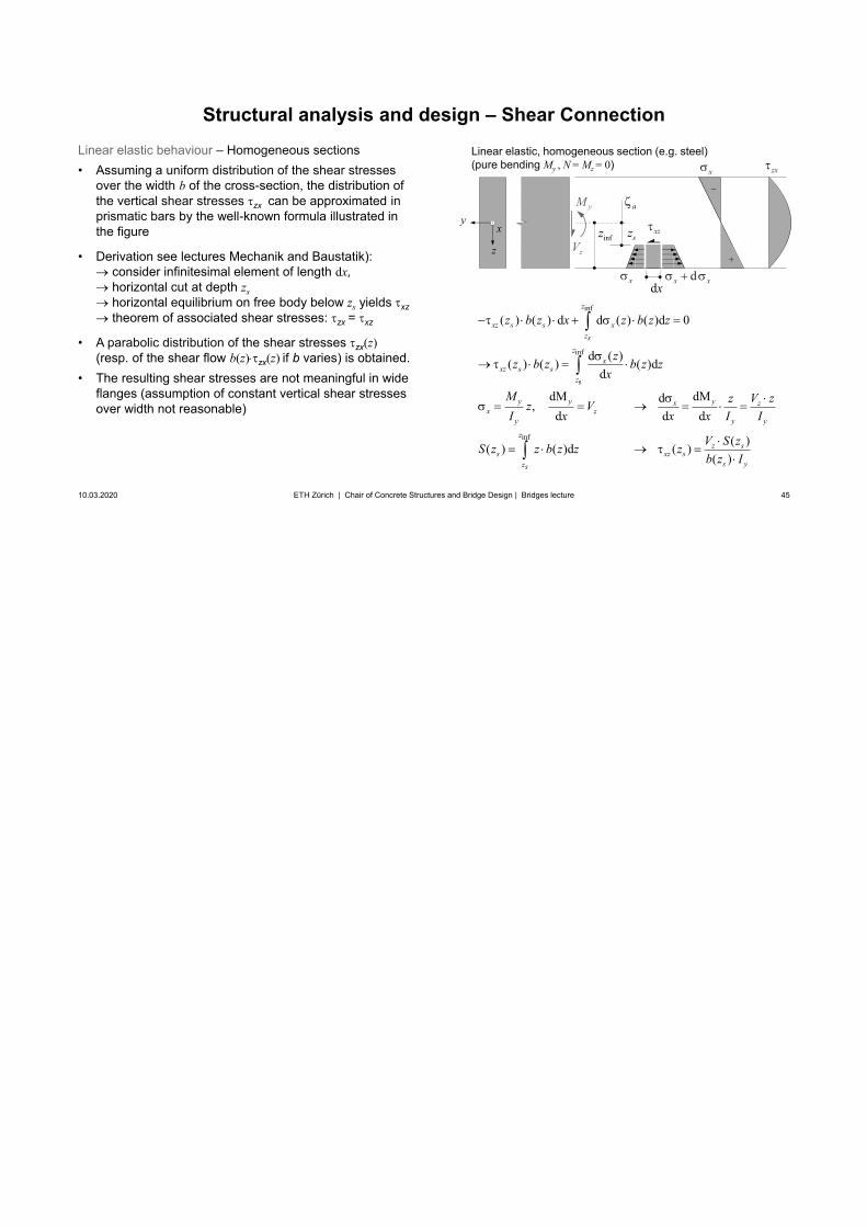
Linear elastic behaviour – Homogeneous sections• Assuming a uniform distribution of the shear stresses
over the width b of the cross-section, the distribution ofthe vertical shear stresses zx can be approximated inprismatic bars by the well-known formula illustrated inthe figure
• Derivation see lectures Mechanik and Baustatik):consider infinitesimal element of length dx,horizontal cut at depth zshorizontal equilibrium on free body below zs yields xztheorem of associated shear stresses: zx = xz
• A parabolic distribution of the shear stresses zx(z)(resp. of the shear flow b(z) zx(z) if b varies) is obtained.
• The resulting shear stresses are not meaningful in wideflanges (assumption of constant vertical shear stressesover width not reasonable)
Linear elastic, homogeneous section (e.g. steel)(pure bending My , N = Mz = 0)
a
Note again that in composite bridge design, contrary to reinforced concrete analysis, steel is conventionally used as reference material, but the definition n = Ea / Ec is maintained (i.e., n>1). The transformed section properties (ideelle Querschnittswerte) Ai, Iyi etc. are referred to Ea , and concrete areas have to be divided by n: Axial stiffness “EA” = Ea Ai, bending stiffness “EI” = Ea Ii etc.Consequently, Ai = Aa + Ac / n (rather than Ai = Ac + nAs in reinforced concrete). Therefore, the modular ratio is referred to as “Reduktionszahl” (rather than “Wertigkeit” as in concrete) in the German version of EN 1994.
46
Structural analysis and design – Shear Connection
10.03.2020 46ETH Zürich | Chair of Concrete Structures and Bridge Design | Bridges lecture
inf
( )
inf
( )
inf
( )
( ) ( ) d d ( , ) d 0
d ( , )
1
( )( )(
( ) ( ) dd
dM dMd1 1, d d d
d( ))
y
z i sx
z
xz s s xz b zs
zx
xz s
i
sz b zs
y y x zx z
yi yi yi
z
i sz b zs
z ss y
z b z x y z A
y zz b z Ax
M V zzz Vn I x x n x I n
A V S zb
I
zS z zzn I
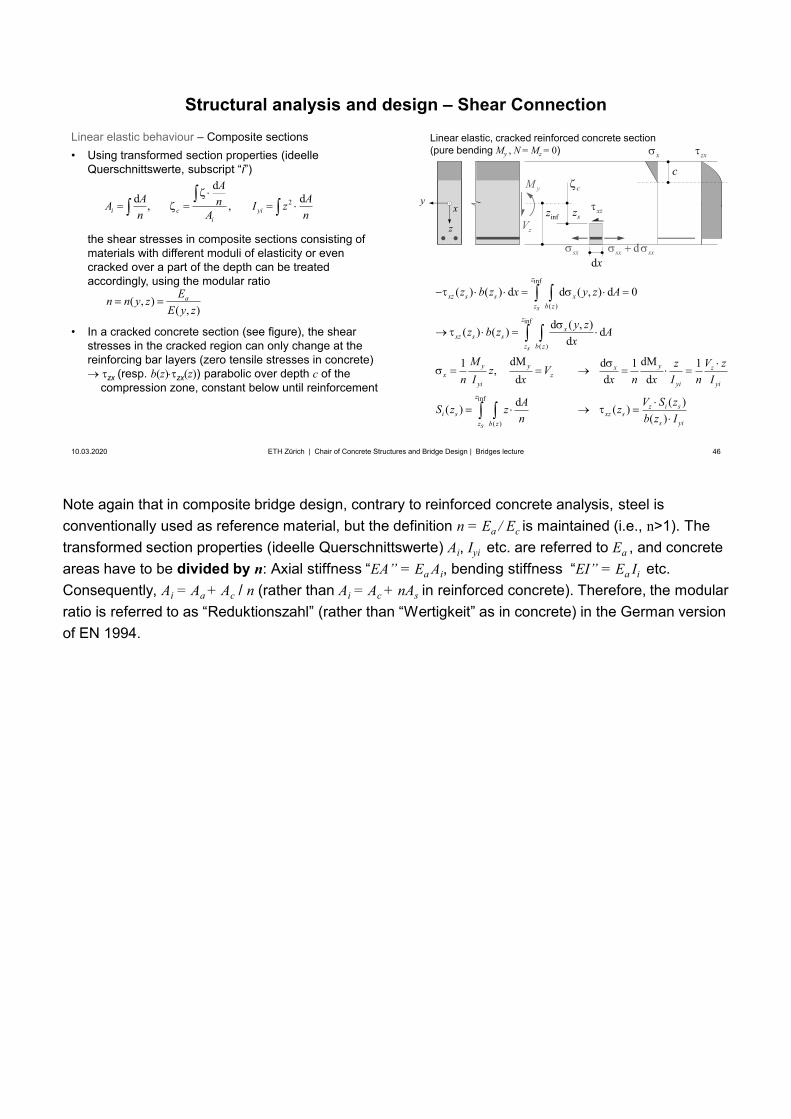
Linear elastic behaviour – Composite sections• Using transformed section properties (ideelle
Querschnittswerte, subscript “i”)
the shear stresses in composite sections consisting of materials with different moduli of elasticity or even cracked over a part of the depth can be treated accordingly, using the modular ratio
• In a cracked concrete section (see figure), the shearstresses in the cracked region can only change at thereinforcing bar layers (zero tensile stresses in concrete)
zx (resp. b(z) zx(z)) parabolic over depth c of thecompression zone, constant below until reinforcement
Linear elastic, cracked reinforced concrete section (pure bending My , N = Mz = 0)
z
xy
x zx
dsx sxsx
xzinfz sz
dx
zV
yMc
c
( , )( , )
aEn n y zE y z
2
dd d, ,i c yi
i
AA AnA I zn A n
47
Structural analysis and design – Shear Connection
10.03.2020 47ETH Zürich | Chair of Concrete Structures and Bridge Design | Bridges lecture
( )sup
( )sup
( )sup
( ) ( ) d d ( , ) d 0
d ( , )( ) ( ) dd
dM dMd1 1 1, d d d
d( ( )( ))( )
z ci sxz s
s yi
zs
xz s s xz b z
zsx
xz s sz b z
y y yx zx z
yi yi yi
zs
ci sz b z
V
z b z x y z A
y zz b z Ax
M V zzz Vn I x x n x I n I
IAS S zzz z
b zn
Linear elastic behaviour – Composite sections• In T-beams, the shear stresses at the interface of deck
and girder are of primary interest (zs = interface level)
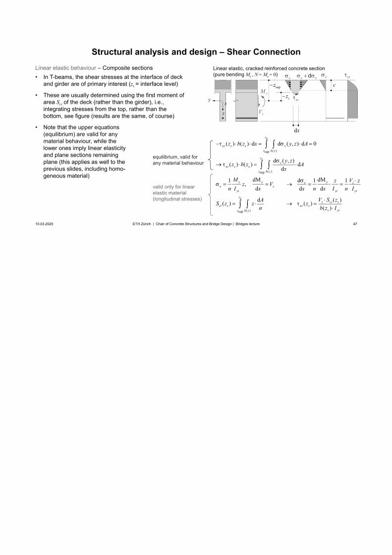
• These are usually determined using the first moment ofarea Sci of the deck (rather than the girder), i.e.,integrating stresses from the top, rather than thebottom, see figure (results are the same, of course)
• Note that the upper equations(equilibrium) are valid for anymaterial behaviour, while thelower ones imply linear elasticityand plane sections remainingplane (this applies as well to theprevious slides, including homo-geneous material)
Linear elastic, cracked reinforced concrete section (pure bending My , N = Mz = 0)
z
xy
x zx
xz
supz
sz
dx
zV
yMc
equilibrium, valid for any material behaviour
valid only for linearelastic material(longitudinal stresses)
x xdx
48
Structural analysis and design – Shear Connection
10.03.2020 48ETH Zürich | Chair of Concrete Structures and Bridge Design | Bridges lecture
( )sup
( )sup
( )sup
( ) ( ) d d ( , ) d 0
d ( , )( ) ( ) dd
dM dMd1 1 1, d d d
d( ( )( ))( )
z ci sxz s
s yi
zs
xz s s xz b z
zsx
xz s sz b z
y y yx zx z
yi yi yi
zs
ci sz b z
V
z b z x y z A
y zz b z Ax
M V zzz Vn I x x n x I n I
IAS S zzz z
b zn
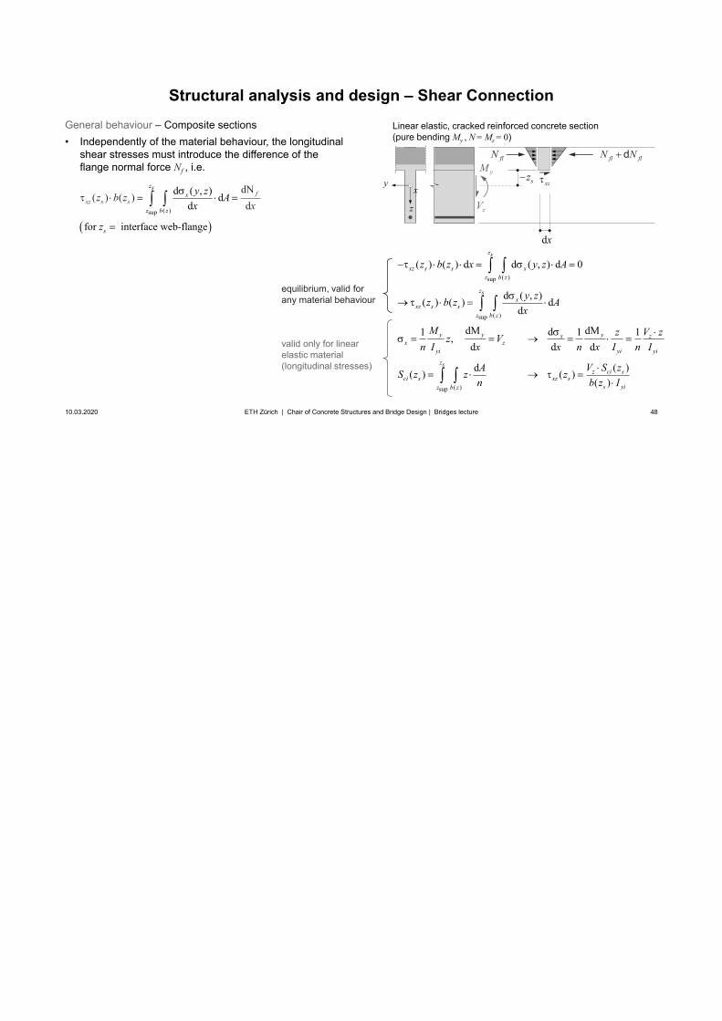
General behaviour – Composite sections• Independently of the material behaviour, the longitudinal
shear stresses must introduce the difference of theflange normal force Nf , i.e.
Linear elastic, cracked reinforced concrete section (pure bending My , N = Mz = 0)
z
xy xzsz
dx
zV
yM
equilibrium, valid for any material behaviour
valid only for linearelastic material(longitudinal stresses)
( )sup
d ( , ) dd d
for interface web-flange
dN( ) ( )
zsx
z
fxz s
b
s
sz x
z b zx
y z A
z
fl flN NdflN
49
Structural analysis and design – Shear Connection
10.03.2020 49ETH Zürich | Chair of Concrete Structures and Bridge Design | Bridges lecture
z
xy
z
xy
, ,, x cx a , ,, zx czx a
, ,, x cx a , ,, zx czx a
Linear elastic steel-concrete composite section, positive My(N = Mz = 0)
Linear elastic steel-concrete composite section, negative My(N = Mz = 0)
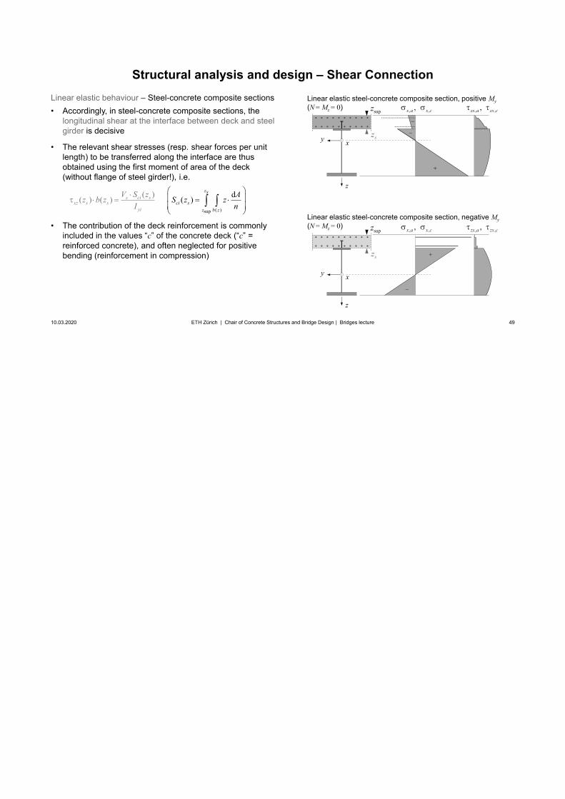
Linear elastic behaviour – Steel-concrete composite sections• Accordingly, in steel-concrete composite sections, the
longitudinal shear at the interface between deck and steelgirder is decisive
• The relevant shear stresses (resp. shear forces per unitlength) to be transferred along the interface are thusobtained using the first moment of area of the deck(without flange of steel girder!), i.e.
• The contribution of the deck reinforcement is commonlyincluded in the values “c” of the concrete deck (“c” =reinforced concrete), and often neglected for positivebending (reinforcement in compression)
supz
sz
supz
sz
( )sup
( )( ) ( ) d( )z ci sxz s s
yi
zs
ci sz b z
V S zz b zI
AS z zn
50
Structural analysis and design – Shear Connection
10.03.2020 50ETH Zürich | Chair of Concrete Structures and Bridge Design | Bridges lecture
z
xy
z
xy
, ,, x cx a , ,, zx czx a
, ,, x cx a , ,, zx czx a
Linear elastic steel-concrete composite section, positive My(N = Mz = 0)
Linear elastic steel-concrete composite section, negative My(N = Mz = 0)
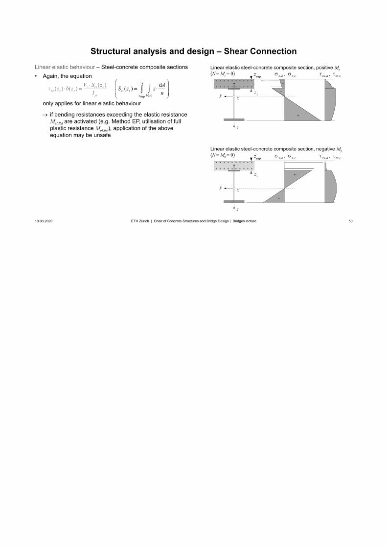
Linear elastic behaviour – Steel-concrete composite sections• Again, the equation
only applies for linear elastic behaviour
if bending resistances exceeding the elastic resistance Mel,Rd are activated (e.g. Method EP, utilisation of full plastic resistance Mpl,Rd), application of the above equation may be unsafe
supz
sz
supz
sz
( )sup
( )( ) ( ) d( )z ci sxz s s
yi
zs
ci sz b z
V S zz b zI
AS z zn
51
Structural analysis and design – Shear Connection
10.03.2020 51ETH Zürich | Chair of Concrete Structures and Bridge Design | Bridges lecture
z
xy
z
xy
Linear elastic steel-concrete composite section, positive My(N = Mz = 0)
Linear elastic steel-concrete composite section, negative My(N = Mz = 0)
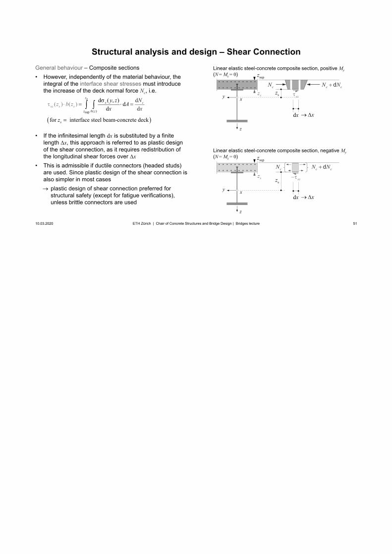
General behaviour – Composite sections• However, independently of the material behaviour, the
integral of the interface shear stresses must introducethe increase of the deck normal force Nc, i.e.
• If the infinitesimal length dx is substituted by a finitelength x, this approach is referred to as plastic designof the shear connection, as it requires redistribution ofthe longitudinal shear forces over x
• This is admissible if ductile connectors (headed studs)are used. Since plastic design of the shear connection isalso simpler in most cases
plastic design of shear connection preferred forstructural safety (except for fatigue verifications), unless brittle connectors are used
supz
sz
supz
sz
( )sup
k
dd
d ( , ) dd
for interface steel beam-conc
)
rete d c
(
e
( )z
xc
sx
z b
s
zz
s sz bx
z A Nx
y z
z
xz
dx
c cN NdcNsz
xzsz
c cN NdcN
dx
x
x
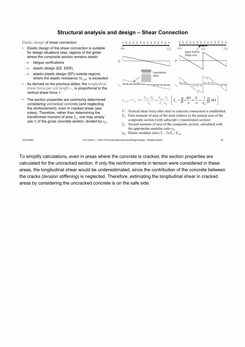
To simplify calculations, even in areas where the concrete is cracked, the section properties are calculated for the uncracked section. If only the reinforcements in tension were considered in these areas, the longitudinal shear would be underestimated, since the contribution of the concrete between the cracks (tension stiffening) is neglected. Therefore, estimating the longitudinal shear in cracked areas by considering the uncracked concrete is on the safe side.
52
V : Vertical shear force after steel to concrete connection is establishedSc: First moment of area of the deck relative to the neutral axis of the
composite section (with subscript i: transformed section)Ib: Second moment of area of the composite section, calculated with
the appropriate modular ratio nel nel: Elastic modular ratio (1…3) Ea / Ecm
Structural analysis and design – Shear Connection
10.03.2020 52ETH Zürich | Chair of Concrete Structures and Bridge Design | Bridges lecture
Elastic design of shear connection• Elastic design of the shear connection is suitable
for design situations resp. regions of the girderwhere the composite section remains elastic
fatigue verificationselastic design (EE, EER)elastic-plastic design (EP) outside regionswhere the elastic resistance Mel,Rd is exceeded
• As derived on the previous slides, the longitudinalshear force per unit length vel is proportional to thevertical shear force V
• The section properties are commonly determinedconsidering uncracked concrete (and neglectingthe reinforcement), even in cracked areas (seenotes). Therefore, rather than determining thetransformed moment of area Sci, one may simplyuse Sc of the gross concrete section, divided by nel.
,1Ed ci Ed c
L Ed xze
cci
elb b l
V S V Sv bI I nn
SAS z z An n
d d
larger bottom flange area
longitudinal shear
V
vL
V
vL
53
Structural analysis and design – Shear Connection
10.03.2020 53ETH Zürich | Chair of Concrete Structures and Bridge Design | Bridges lecture
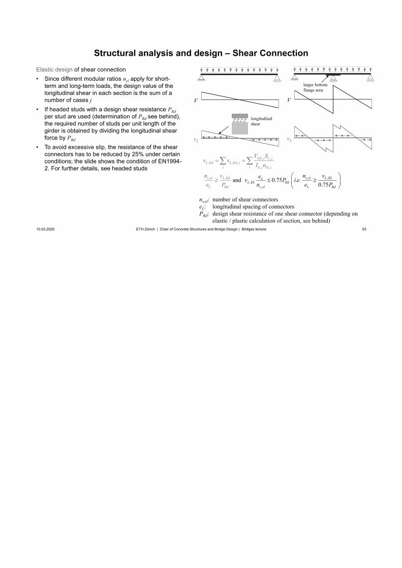
Elastic design of shear connection• Since different modular ratios nel apply for short-
term and long-term loads, the design value of thelongitudinal shear in each section is the sum of anumber of cases j
• If headed studs with a design shear resistance PRdper stud are used (determination of PRd see behind),the required number of studs per unit length of thegirder is obtained by dividing the longitudinal shearforce by PRd
• To avoid excessive slip, the resistance of the shearconnectors has to be reduced by 25% under certainconditions; the slide shows the condition of EN1994-2. For further details, see headed studs
, ,, , ,
, ,
Ed j c jL Ed L Ed j
j i b j el j
V Sv v
I n
nv,el: number of shear connectorseL: longitudinal spacing of connectorsPRd: design shear resistance of one shear connector (depending on
elastic / plastic calculation of section, see behind)
larger bottom flange area
,, , , ,
,
and 0.75 . .0.75
v el L EkLL Ek Rd
v e d
v el L
L l
d
LRd R
EnP
nv vev P i ee n e P
V
vL
V
vL
longitudinal shear
54
Structural analysis and design – Shear Connection
10.03.2020 54ETH Zürich | Chair of Concrete Structures and Bridge Design | Bridges lecture
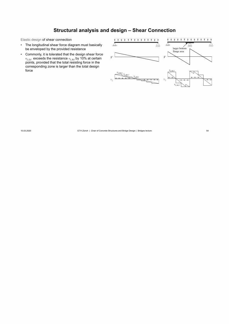
Elastic design of shear connection• The longitudinal shear force diagram must basically
be enveloped by the provided resistance• Commonly, it is tolerated that the design shear force
vL,Ed exceeds the resistance vL,Rd by 10% at certainpoints, provided that the total resisting force in thecorresponding zone is larger than the total designforce vL,Rd,1
vL,Rd,2
vL,Rd,i
vL,Rd,1 vL,Rd,2
larger bottom flange area
V
vL
V
vL
This approach corresponds to a plastic design of the shear connectors over the length AB nextslides
55
Structural analysis and design – Shear Connection
10.03.2020 55ETH Zürich | Chair of Concrete Structures and Bridge Design | Bridges lecture
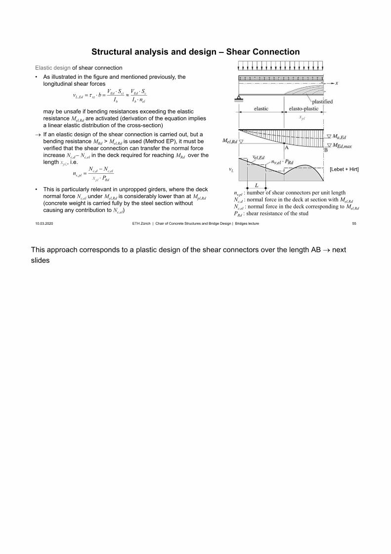
Elastic design of shear connection• As illustrated in the figure and mentioned previously, the
longitudinal shear forces
may be unsafe if bending resistances exceeding the elastic resistance Mel,Rd are activated (derivation of the equation implies a linear elastic distribution of the cross-section)If an elastic design of the shear connection is carried out, but a bending resistance MRd > Mel,Rd is used (Method EP), it must be verified that the shear connection can transfer the normal force increase Nc,d Nc,el in the deck required for reaching MRd over the length xpl,, i.e.
• This is particularly relevant in unpropped girders, where the decknormal force Nc,el under Mel,Rd is considerably lower than at Mpl,Rd(concrete weight is carried fully by the steel section withoutcausing any contribution to Nc,el)
vL, ,,
p dl
c d c elv pl
R
N Nx
nP
,Ed ci Ed c
L Ed xzb b el
V S V Sv bI I n
[Lebet + Hirt]
nv,pl : number of shear connectors per unit lengthNc,d : normal force in the deck at section with Mel,RdNc,el : normal force in the deck corresponding to Mel,RdPRd : shear resistance of the stud
xpl
56
Structural analysis and design – Shear Connection
10.03.2020 56ETH Zürich | Chair of Concrete Structures and Bridge Design | Bridges lecture
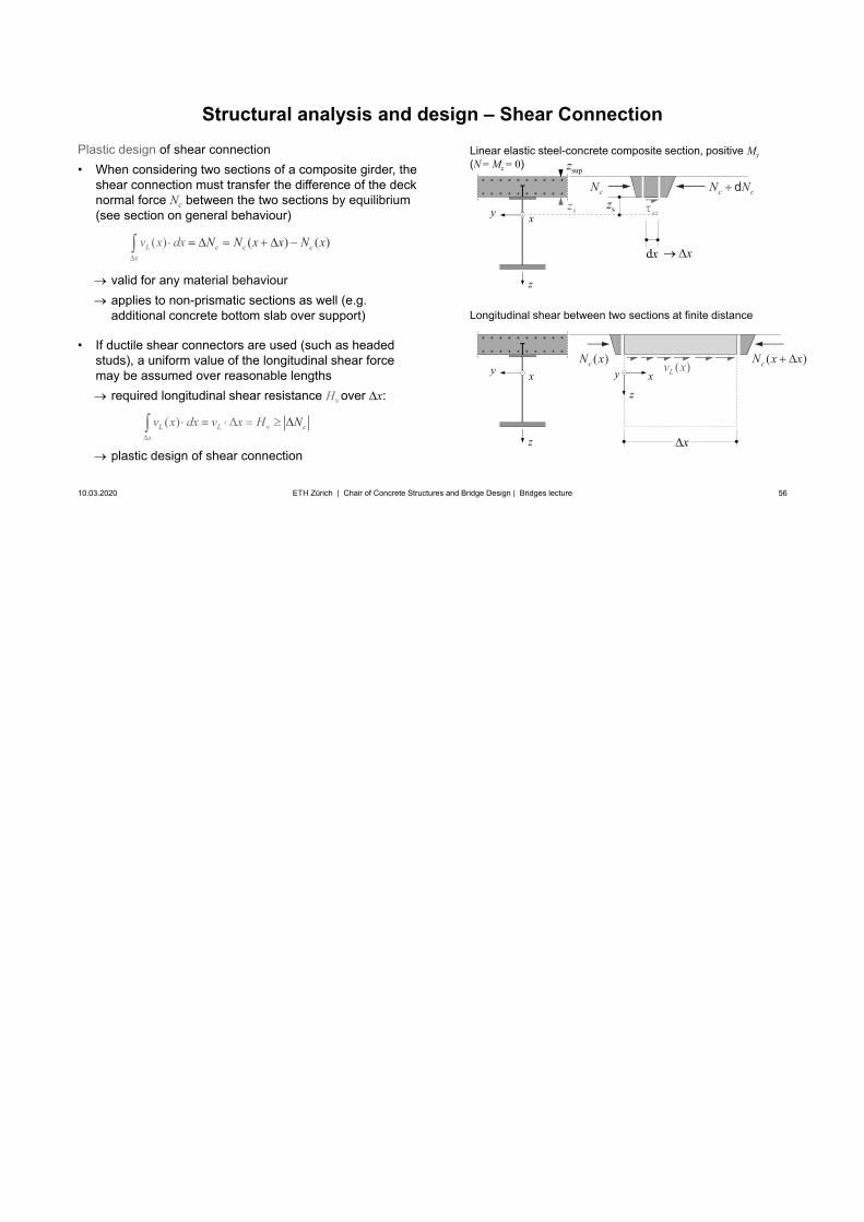
Plastic design of shear connection• When considering two sections of a composite girder, the
shear connection must transfer the difference of the decknormal force Nc between the two sections by equilibrium(see section on general behaviour)
valid for any material behaviourapplies to non-prismatic sections as well (e.g. additional concrete bottom slab over support)
• If ductile shear connectors are used (such as headedstuds), a uniform value of the longitudinal shear forcemay be assumed over reasonable lengths
required longitudinal shear resistance Hv over x:
plastic design of shear connection
( )( () )c cL cx
v Nx N N x x xdx
Longitudinal shear between two sections at finite distance
z
xy
supz
szxz
dx
c cN NdcNsz
x
z
xy ( )Lv x ( )cN x x( )cN x
zxy
x
Linear elastic steel-concrete composite section, positive My(N = Mz = 0)
( ) cL L vx
v x dx v x H N
Providing a shear connection for the full plastic bending resistances may require an excessive number of connectors in cases where the full moment capacity (particularly regarding full activation of the concrete deck or bottom slab in case of double composite action in compression) is not required for bending resistance. In such cases, many designers merely provide a connection to activate the required bending resistance.
57
Structural analysis and design – Shear Connection
10.03.2020 57ETH Zürich | Chair of Concrete Structures and Bridge Design | Bridges lecture
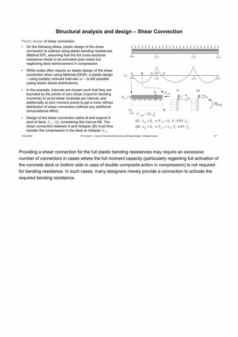
Plastic design of shear connection• On the following slides, plastic design of the shear
connection is outlined using plastic bending resistances(Method EP), assuming that the full cross-sectionalresistance needs to be activated (see notes) butneglecting deck reinforcement in compression
• While codes often require an elastic design of the shearconnection when using Methods EE(R), a plastic design– using suitably reduced intervals x – is still possible(using elastic stress distributions)
• In the example, intervals are chosen such that they arebounded by the points of zero shear (max/min bendingmoments) to avoid shear reversals per interval, andadditionally at zero moment points to get a more refineddistribution of shear connectors (without any additionalcomputational effort)
• Design of the shear connection starts at end support A(end of deck, Nc,A =0), considering the interval AB. Theshear connection between A and midspan (B) must thustransfer the compression in the deck at midspan Nc,B
MyA B DC
A B
Nc,BNc,A=0 xpl
Mpl,Rd
(I)
xpl
(II)hc
,
,
(I) :
(II) :
0.
85
85
0.c B c c cd
c B pl c cd
pl c
pl c
N h b f
N x
x h
fx bh
, ,Bv cH NAB
E
58
Structural analysis and design – Shear Connection
10.03.2020 58ETH Zürich | Chair of Concrete Structures and Bridge Design | Bridges lecture
MyA B DC
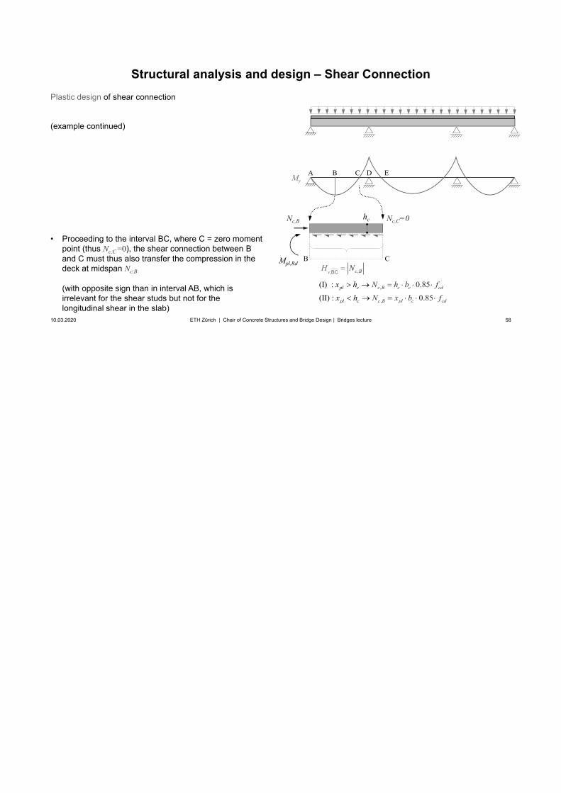
B C
Nc,B hc Nc,C=0
, ,Bv cH NBC
E
Plastic design of shear connection
(example continued)
• Proceeding to the interval BC, where C = zero momentpoint (thus Nc,C =0), the shear connection between Band C must thus also transfer the compression in thedeck at midspan Nc,B
(with opposite sign than in interval AB, which isirrelevant for the shear studs but not for thelongitudinal shear in the slab)
,
,
(I) :
(II) :
0.
85
85
0.c B c c cd
c B pl c cd
pl c
pl c
N h b f
N x
x h
fx bh
Mpl,Rd
59
Structural analysis and design – Shear Connection
10.03.2020 59ETH Zürich | Chair of Concrete Structures and Bridge Design | Bridges lecture
MyA B DC
C D
hc Nc,D
,c D s sdN A f
Nc,D=-As fsd
Mpl,Rd
Nc,C=0
, ,Dv cH NCD
E
Plastic design of shear connection
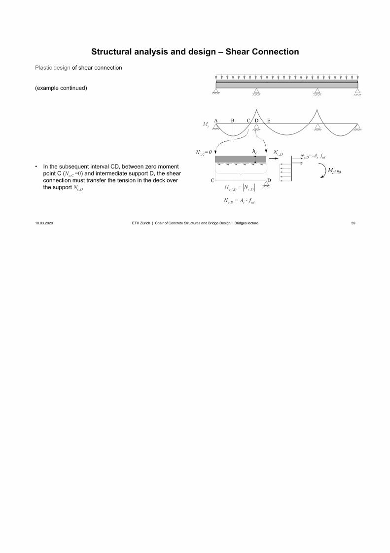
(example continued)
• In the subsequent interval CD, between zero momentpoint C (Nc,C =0) and intermediate support D, the shearconnection must transfer the tension in the deck overthe support Nc,D
60
Structural analysis and design – Shear Connection
10.03.2020 60ETH Zürich | Chair of Concrete Structures and Bridge Design | Bridges lecture
MyA B DC
D E
E
hc
, ,Dv cH NDE
Nc,D Nc,E=0
,c D s sdN A f
Plastic design of shear connection
(example continued)
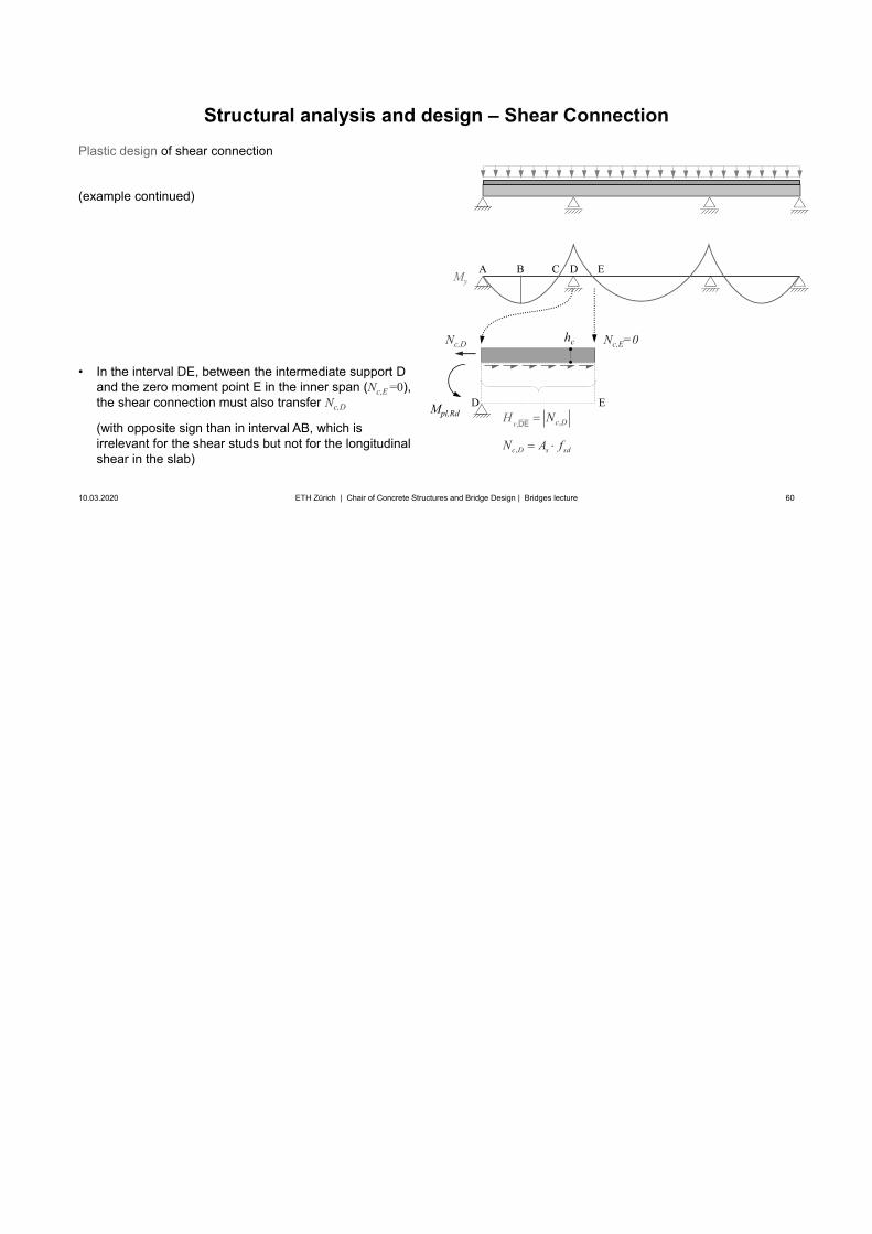
• In the interval DE, between the intermediate support Dand the zero moment point E in the inner span (Nc,E =0),the shear connection must also transfer Nc,D
(with opposite sign than in interval AB, which isirrelevant for the shear studs but not for the longitudinalshear in the slab)
Mpl,Rd
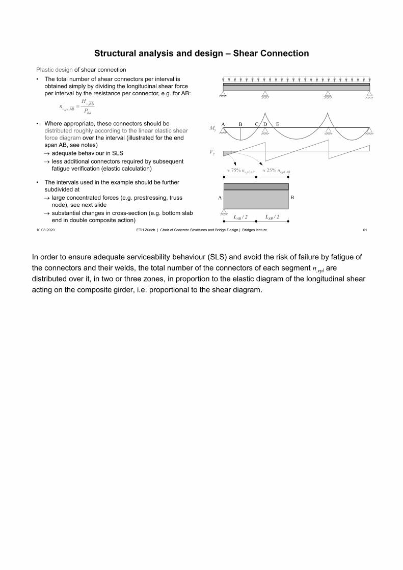
In order to ensure adequate serviceability behaviour (SLS) and avoid the risk of failure by fatigue of the connectors and their welds, the total number of the connectors of each segment n,vpl aredistributed over it, in two or three zones, in proportion to the elastic diagram of the longitudinal shear acting on the composite girder, i.e. proportional to the shear diagram.
61
Structural analysis and design – Shear Connection
10.03.2020 61ETH Zürich | Chair of Concrete Structures and Bridge Design | Bridges lecture
Plastic design of shear connection• The total number of shear connectors per interval is
obtained simply by dividing the longitudinal shear forceper interval by the resistance per connector, e.g. for AB:
• Where appropriate, these connectors should bedistributed roughly according to the linear elastic shearforce diagram over the interval (illustrated for the endspan AB, see notes)
adequate behaviour in SLSless additional connectors required by subsequentfatigue verification (elastic calculation)
• The intervals used in the example should be furthersubdivided at
large concentrated forces (e.g. prestressing, trussnode), see next slidesubstantial changes in cross-section (e.g. bottom slab end in double composite action)
A B
LAB / 2 LAB / 2
25% nv,pl,AB75% nv,pl,AB
MyA B DC E
,, ,
vv pl
Rd
Hn
PAB
AB
Vz
Illustrations adapted from J.P. Lebet and M.A. Hirt, Steel bridges
62
Structural analysis and design – Shear Connection
10.03.2020 62ETH Zürich | Chair of Concrete Structures and Bridge Design | Bridges lecture
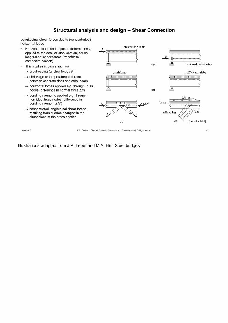
Longitudinal shear forces due to (concentrated) horizontal loads• Horizontal loads and imposed deformations,
applied to the deck or steel section, causelongitudinal shear forces (transfer tocomposite section)
• This applies in cases such as:prestressing (anchor forces P)shrinkage or temperature differencebetween concrete deck and steel beamhorizontal forces applied e.g. through truss nodes (difference in normal force N)bending moments applied e.g. through non-ideal truss nodes (difference in bending moment M )concentrated longitudinal shear forces resulting from sudden changes in the dimensions of the cross-section
[Lebet + Hirt]
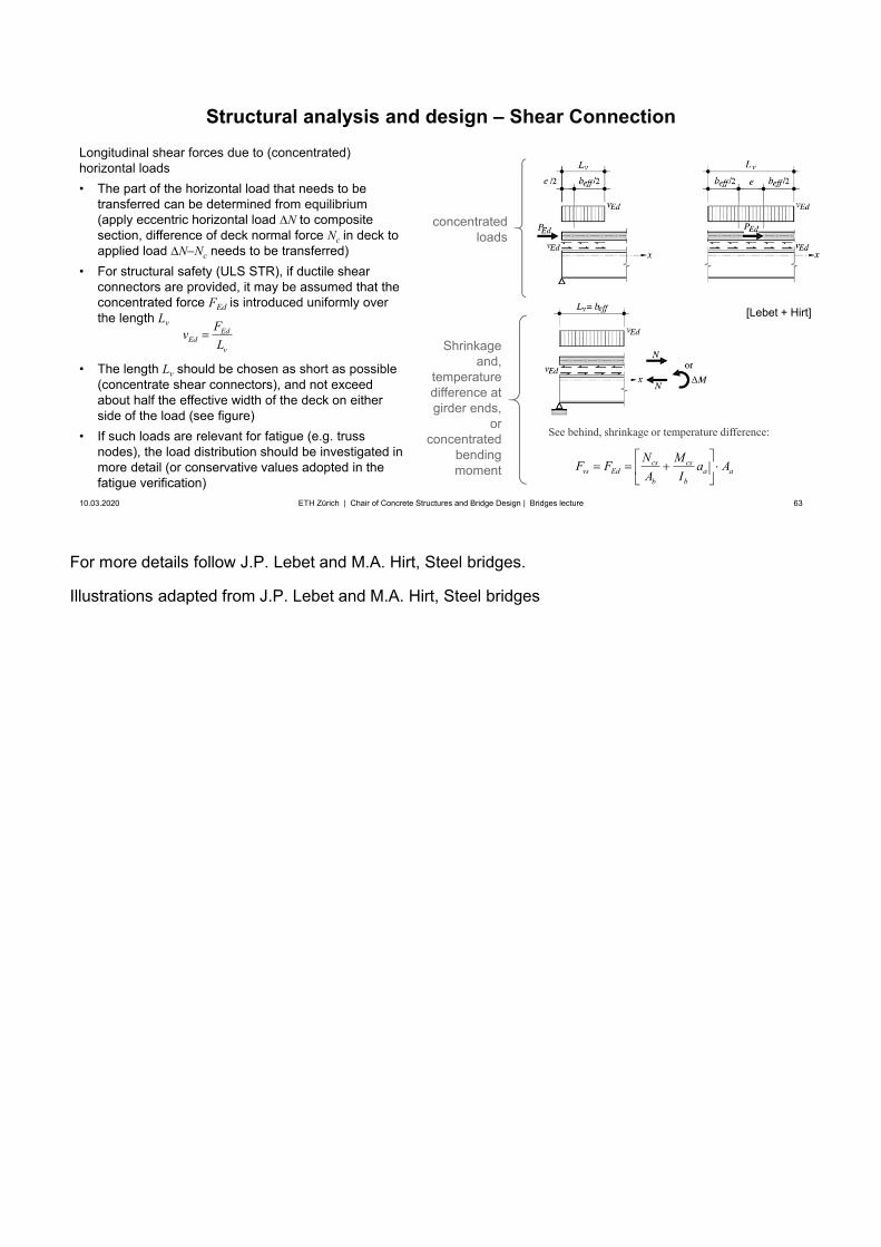
For more details follow J.P. Lebet and M.A. Hirt, Steel bridges.
Illustrations adapted from J.P. Lebet and M.A. Hirt, Steel bridges
63
Structural analysis and design – Shear Connection
10.03.2020 63ETH Zürich | Chair of Concrete Structures and Bridge Design | Bridges lecture
Longitudinal shear forces due to (concentrated) horizontal loads• The part of the horizontal load that needs to be
transferred can be determined from equilibrium(apply eccentric horizontal load N to compositesection, difference of deck normal force Nc in deck toapplied load N Nc needs to be transferred)
• For structural safety (ULS STR), if ductile shearconnectors are provided, it may be assumed that theconcentrated force FEd is introduced uniformly overthe length Lv
• The length Lv should be chosen as short as possible(concentrate shear connectors), and not exceedabout half the effective width of the deck on eitherside of the load (see figure)
• If such loads are relevant for fatigue (e.g. trussnodes), the load distribution should be investigated inmore detail (or conservative values adopted in thefatigue verification)
EdEd
v
FvL
concentrated loads
Shrinkage and,
temperaturedifference at girder ends,
orconcentrated
bending moment
cs csvs Ed a a
b b
N MF F a AA I
See behind, shrinkage or temperature difference:
[Lebet + Hirt]
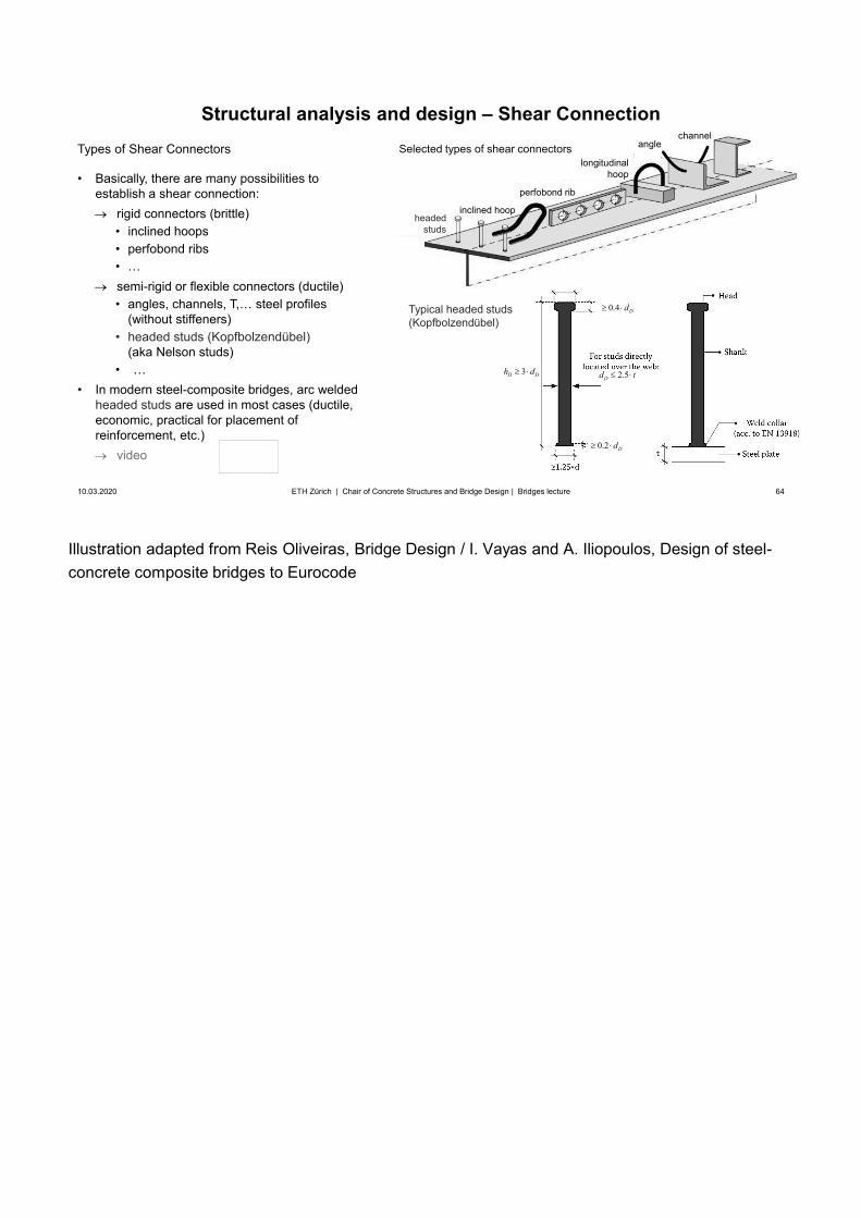
Illustration adapted from Reis Oliveiras, Bridge Design / I. Vayas and A. Iliopoulos, Design of steel-concrete composite bridges to Eurocode
64
1.5 Dd
0.4 Dd
2.5Dd t
0.2 Dd
3D Dh d
Types of Shear Connectors
• Basically, there are many possibilities toestablish a shear connection:
rigid connectors (brittle)• inclined hoops• perfobond ribs• …semi-rigid or flexible connectors (ductile)• angles, channels, T,… steel profiles
(without stiffeners)• headed studs (Kopfbolzendübel)
(aka Nelson studs)• …
• In modern steel-composite bridges, arc weldedheaded studs are used in most cases (ductile,economic, practical for placement ofreinforcement, etc.)
video
Structural analysis and design – Shear Connection
10.03.2020 64ETH Zürich | Chair of Concrete Structures and Bridge Design | Bridges lecture
Selected types of shear connectors
Typical headed studs(Kopfbolzendübel)
headedstuds
inclined hoop
perfobond rib
longitudinalhoop
anglechannel
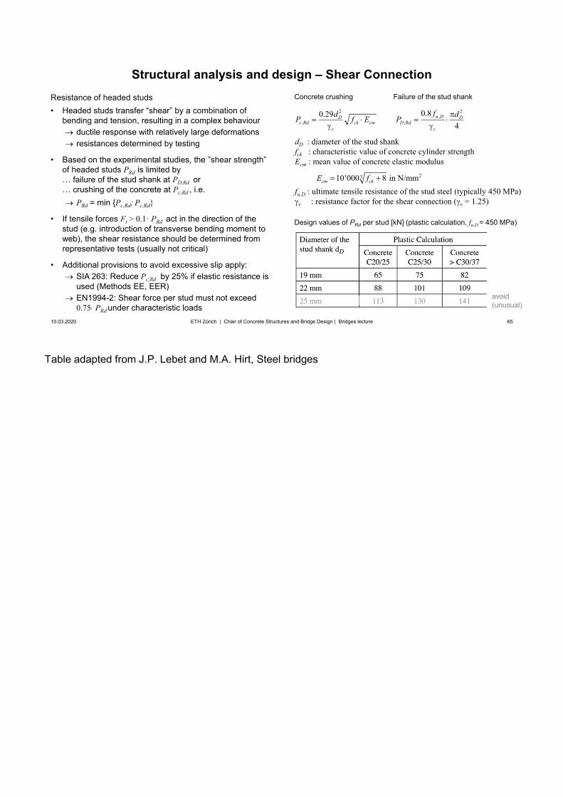
Table adapted from J.P. Lebet and M.A. Hirt, Steel bridges
65
2
,0.29 D
c Rd ck cmv
dP f E2
,,
0.84
u D DD Rd
v
f dP
Concrete crushing Failure of the stud shank
dD : diameter of the stud shankfck : characteristic value of concrete cylinder strengthEcm : mean value of concrete elastic modulus
fu,D : ultimate tensile resistance of the stud steel (typically 450 MPa)v : resistance factor for the shear connection ( v = 1.25)
2310'000 8 in N/mmcm ckE f
Resistance of headed studs• Headed studs transfer “shear” by a combination of
bending and tension, resulting in a complex behaviourductile response with relatively large deformationsresistances determined by testing
• Based on the experimental studies, the ”shear strength”of headed studs PRd is limited by… failure of the stud shank at PD,Rd or… crushing of the concrete at Pc,Rd , i.e.
PRd = min {Pc,Rd; Pc,Rd}
• If tensile forces Ft > 0.1· PRd act in the direction of thestud (e.g. introduction of transverse bending moment toweb), the shear resistance should be determined fromrepresentative tests (usually not critical)
• Additional provisions to avoid excessive slip apply:SIA 263: Reduce Pc,Rd by 25% if elastic resistance isused (Methods EE, EER)EN1994-2: Shear force per stud must not exceed 0.75 PRd under characteristic loads
Structural analysis and design – Shear Connection
10.03.2020 65ETH Zürich | Chair of Concrete Structures and Bridge Design | Bridges lecture
Design values of PRd per stud [kN] (plastic calculation, fu,D = 450 MPa)
avoid(unusual)
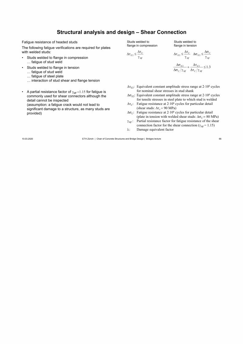
66
Fatigue resistance of headed studsThe following fatigue verifications are required for plates with welded studs:• Studs welded to flange in compression
… fatigue of stud weld• Studs welded to flange in tension
… fatigue of stud weld… fatigue of steel plate… interaction of stud shear and flange tension
• A partial resistance factor of Mf 1.15 for fatigue iscommonly used for shear connectors although thedetail cannot be inspected(assumption: a fatigue crack would not lead tosignificant damage to a structure, as many studs areprovided)
Structural analysis and design – Shear Connection
10.03.2020 66ETH Zürich | Chair of Concrete Structures and Bridge Design | Bridges lecture
2 2 1.3E E
C Mf C Mf
Studs welded to flange in compression
E2: Equivalent constant amplitude stress range at 2 106 cycles for nominal shear stresses in stud shank
E2: Equivalent constant amplitude stress range at 2 106 cycles for tensile stresses in steel plate to which stud is welded
C: Fatigue resistance at 2 106 cycles for particular detail(shear studs: c 90 MPa)
C: Fatigue resistance at 2 106 cycles for particular detail (plate in tension with welded shear studs: C 80 MPa)
Mf : Partial resistance factor for fatigue resistance of the shear connection factor for the shear connection ( Mf = 1.15)
: Damage equivalent factor
Studs welded to flange in tension
2C
EMf
2 2C C
E EMf Mf
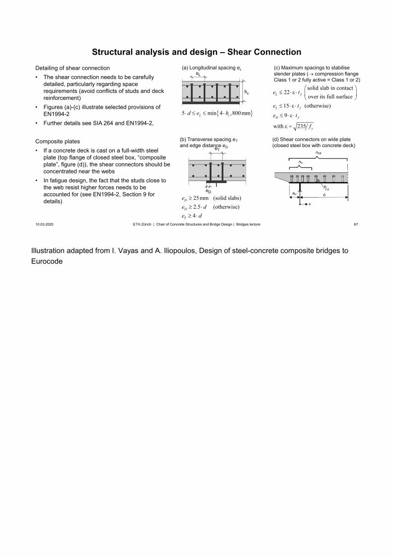
Illustration adapted from I. Vayas and A. Iliopoulos, Design of steel-concrete composite bridges to Eurocode
67
10.03.2020 67ETH Zürich | Chair of Concrete Structures and Bridge Design | Bridges lecture
Detailing of shear connection• The shear connection needs to be carefully
detailed, particularly regarding spacerequirements (avoid conflicts of studs and deckreinforcement)
• Figures (a)-(c) illustrate selected provisions ofEN1994-2
• Further details see SIA 264 and EN1994-2,
Composite plates• If a concrete deck is cast on a full-width steel
plate (top flange of closed steel box, “compositeplate”, figure (d)), the shear connectors should beconcentrated near the webs
• In fatigue design, the fact that the studs close tothe web resist higher forces needs to beaccounted for (see EN1994-2, Section 9 fordetails)
(a) Longitudinal spacing eL
5 min 4 ,800mmL cd e h
25mm (solid slabs)2.5 (otherwise)4
D
D
T
ee de d
(c) Maximum spacings to stabiliseslender plates ( compression flange Class 1 or 2 fully active = Class 1 or 2)
solid slab in contact22
over its full surface15 (otherwise)
9
with 235
L f
L f
D f
y
e t
e t
e t
f
(b) Transverse spacing eTand edge distance eD
(d) Shear connectors on wide plate(closed steel box with concrete deck)
Structural analysis and design – Shear Connection
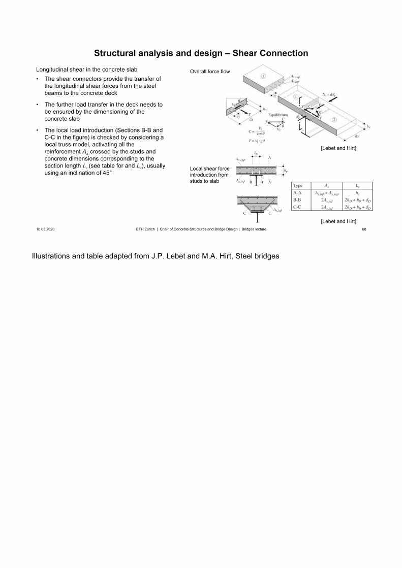
Illustrations and table adapted from J.P. Lebet and M.A. Hirt, Steel bridges
68
Structural analysis and design – Shear Connection
10.03.2020 68ETH Zürich | Chair of Concrete Structures and Bridge Design | Bridges lecture
Longitudinal shear in the concrete slab• The shear connectors provide the transfer of
the longitudinal shear forces from the steelbeams to the concrete deck
• The further load transfer in the deck needs tobe ensured by the dimensioning of theconcrete slab
• The local load introduction (Sections B-B andC-C in the figure) is checked by considering alocal truss model, activating all thereinforcement As crossed by the studs andconcrete dimensions corresponding to thesection length Lc (see table for and Lc), usuallyusing an inclination of 45°
[Lebet and Hirt]
Local shear force introduction from studs to slab
Overall force flow
[Lebet and Hirt]
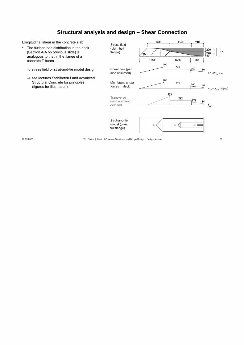
69
Structural analysis and design – Shear Connection
10.03.2020 69ETH Zürich | Chair of Concrete Structures and Bridge Design | Bridges lecture
Stress field(plan, half flange)
Shear flow (perside assumed)
Membrane shear forces in deck
Transverse reinforcement demand
Strut-and-tie model (plan, full flange)
Longitudinal shear in the concrete slab• The further load distribution in the deck
(Section A-A on previous slide) isanalogous to that in the flange of aconcrete T-beam
stress field or strut-and-tie model design
see lectures Stahlbeton I and AdvancedStructural Concrete for principles(figures for illustration)
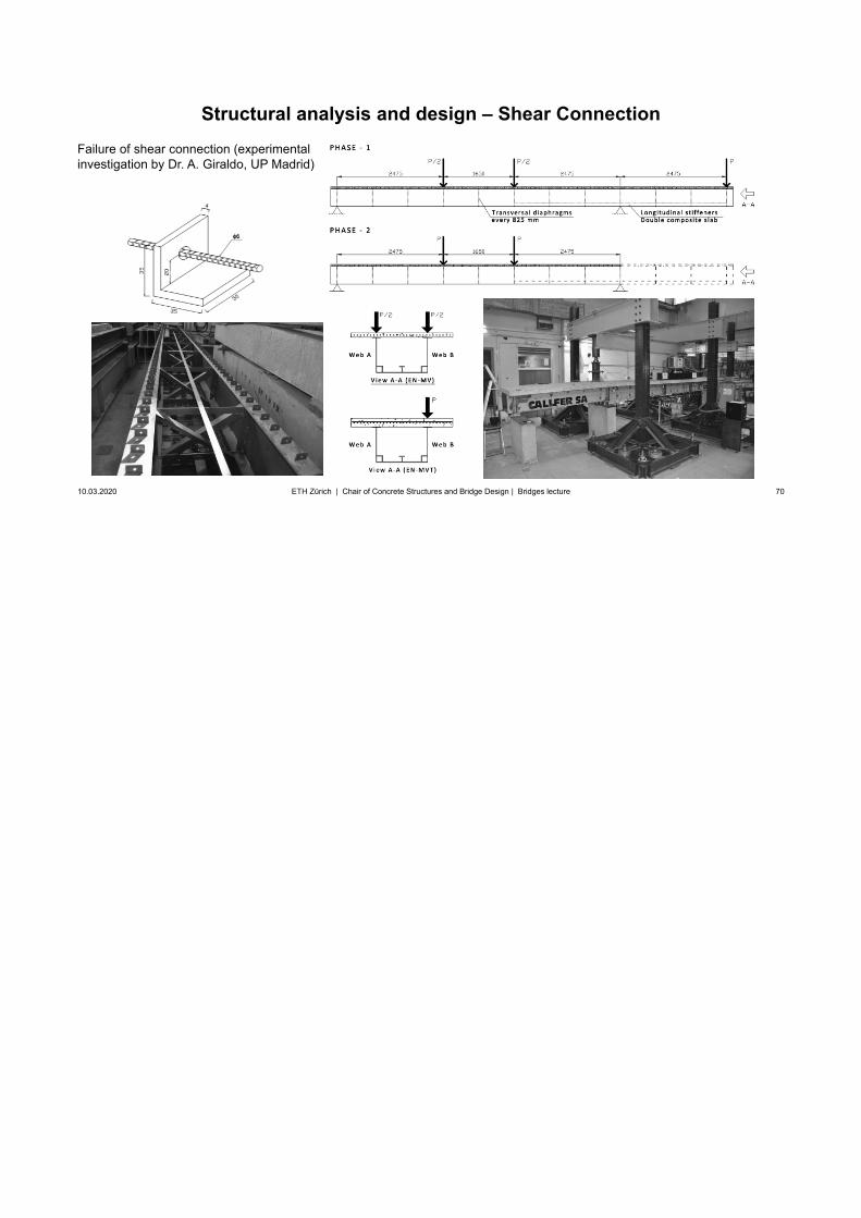
70
Structural analysis and design – Shear Connection
10.03.2020 70ETH Zürich | Chair of Concrete Structures and Bridge Design | Bridges lecture
Failure of shear connection (experimental investigation by Dr. A. Giraldo, UP Madrid)
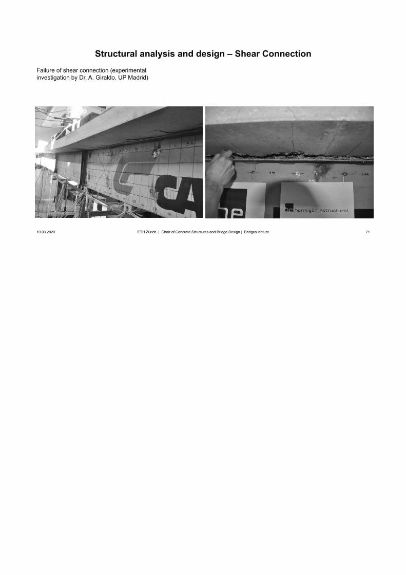
71
Structural analysis and design – Shear Connection
10.03.2020 71ETH Zürich | Chair of Concrete Structures and Bridge Design | Bridges lecture
Failure of shear connection (experimental investigation by Dr. A. Giraldo, UP Madrid)
72
Superstructure / Girder bridges
10.03.2020 72
Design and erectionSteel and steel-concrete composite girders
Structural analysis and design – Further aspects
ETH Zürich | Chair of Concrete Structures and Bridge Design | Bridges lecture
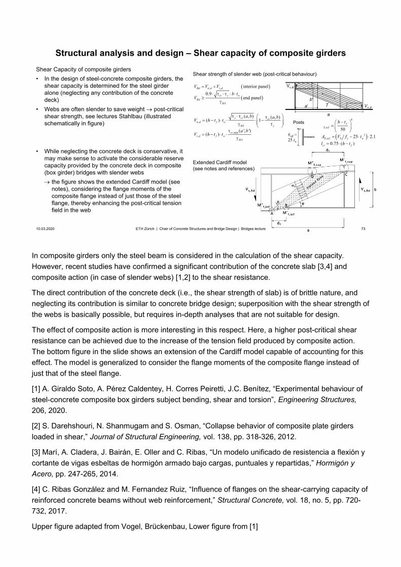
In composite girders only the steel beam is considered in the calculation of the shear capacity. However, recent studies have confirmed a significant contribution of the concrete slab [3,4] and composite action (in case of slender webs) [1,2] to the shear resistance.
The direct contribution of the concrete deck (i.e., the shear strength of slab) is of brittle nature, and neglecting its contribution is similar to concrete bridge design; superposition with the shear strength of the webs is basically possible, but requires in-depth analyses that are not suitable for design.
The effect of composite action is more interesting in this respect. Here, a higher post-critical shear resistance can be achieved due to the increase of the tension field produced by composite action. The bottom figure in the slide shows an extension of the Cardiff model capable of accounting for this effect. The model is generalized to consider the flange moments of the composite flange instead of just that of the steel flange.
[1] A. Giraldo Soto, A. Pérez Caldentey, H. Corres Peiretti, J.C. Benítez, “Experimental behaviour ofsteel-concrete composite box girders subject bending, shear and torsion”, Engineering Structures,206, 2020.
[2] S. Darehshouri, N. Shanmugam and S. Osman, “Collapse behavior of composite plate girdersloaded in shear,” Journal of Structural Engineering, vol. 138, pp. 318-326, 2012.
[3] Marí, A. Cladera, J. Bairán, E. Oller and C. Ribas, “Un modelo unificado de resistencia a flexión ycortante de vigas esbeltas de hormigón armado bajo cargas, puntuales y repartidas,” Hormigón yAcero, pp. 247-265, 2014.
[4] C. Ribas González and M. Fernandez Ruiz, “Influence of flanges on the shear-carrying capacity ofreinforced concrete beams without web reinforcement,” Structural Concrete, vol. 18, no. 5, pp. 720-732, 2017.
Upper figure adapted from Vogel, Brückenbau, Lower figure from [1]
73
beff =25 tw
Structural analysis and design – Shear capacity of composite girders
10.03.2020 73ETH Zürich | Chair of Concrete Structures and Bridge Design | Bridges lecture
Shear Capacity of composite girders• In the design of steel-concrete composite girders, the
shear capacity is determined for the steel girderalone (neglecting any contribution of the concretedeck)
• Webs are often slender to save weight post-criticalshear strength, see lectures Stahlbau (illustratedschematically in figure)
• While neglecting the concrete deck is conservative, itmay make sense to activate the considerable reservecapacity provided by the concrete deck in composite(box girder) bridges with slender webs
the figure shows the extended Cardiff model (seenotes), considering the flange moments of the composite flange instead of just those of the steel flange, thereby enhancing the post-critical tension field in the web
Extended Cardiff model(see notes and references)
Shear strength of slender web (post-critical behaviour)
,1
,min,
1
( , ) ( , )( ) 1
( ', ')( )
y cr crd f w
M y
crd f w
M
a b a bV h t t
a bV h t t
, ,
1
interior panel0.9
end panel
Rd d d
cr y wRd
M
V V Vb t
V
4
,
2,
5025 2.1
0.75 ( )
fS erf
S erf S y w
cr f
h t
A V
I
f tl h t
Posts
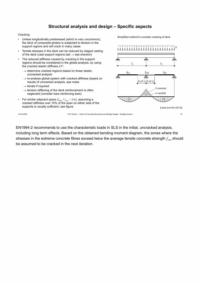
EN1994-2 recommends to use the characteristic loads in SLS in the initial, uncracked analysis, including long term effects. Based on the obtained bending moment diagram, the zones where the stresses in the extreme concrete fibres exceed twice the average tensile concrete strength fctm should be assumed to be cracked in the next iteration.
74
Structural analysis and design – Specific aspects
10.03.2020 74ETH Zürich | Chair of Concrete Structures and Bridge Design | Bridges lecture
Cracking• Unless longitudinally prestressed (which is very uncommon),
the deck of composite girders is subjected to tension in thesupport regions and will crack in many cases
• Tensile stresses in the deck can be reduced by staged castingof the deck (cast support regions last see erection)
• The reduced stiffness caused by cracking in the supportregions should be considered in the global analysis, by usingthe cracked elastic stiffness EIII:
determine cracked regions based on linear elastic,uncracked analysisre-analyse global system with cracked stiffness (based onresults of uncracked analysis, see notesiterate if requiredtension stiffening of the deck reinforcement is oftenneglected (consider bare reinforcing bars)
• For similar adjacent spans (lmin / lmax < 0.6), assuming acracked stiffness over 15% of the span on either side of thesupports is usually sufficient, see figure [Lebet and Hirt (2013)]
Simplified method to consider cracking of deck
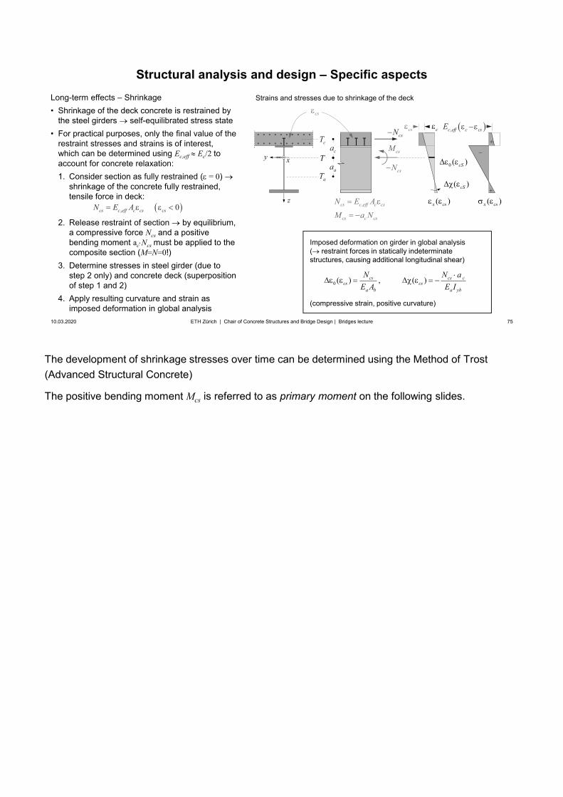
The development of shrinkage stresses over time can be determined using the Method of Trost(Advanced Structural Concrete)
The positive bending moment Mcs is referred to as primary moment on the following slides.
75
Structural analysis and design – Specific aspects
10.03.2020 75ETH Zürich | Chair of Concrete Structures and Bridge Design | Bridges lecture
Long-term effects – Shrinkage• Shrinkage of the deck concrete is restrained by
the steel girders self-equilibrated stress state• For practical purposes, only the final value of the
restraint stresses and strains is of interest,which can be determined using Ec,eff Ec/2 toaccount for concrete relaxation:1. Consider section as fully restrained ( = 0)
shrinkage of the concrete fully restrained,tensile force in deck:
2. Release restraint of section by equilibrium,a compressive force Ncs and a positivebending moment ac Ncs must be applied to thecomposite section (M=N=0!)
3. Determine stresses in steel girder (due tostep 2 only) and concrete deck (superpositionof step 1 and 2)
4. Apply resulting curvature and strain asimposed deformation in global analysis
z
xyca
Strains and stresses due to shrinkage of the deck
csN
csN
csM
aT
cT
T
, 0cs c eff c cs csN E A
cs
Imposed deformation on girder in global analysis( restraint forces in statically indeterminate structures, causing additional longitudinal shear)
(compressive strain, positive curvature)
,cs c eff c cs
cs c cs
N E A
M a N
0 ( ) , ( )cs cs ccs cs
a b a yb
N N aE A E I
aa
( )cS
0 ( )cS
( )x cs( )x cs
cs ,c eff c csEc
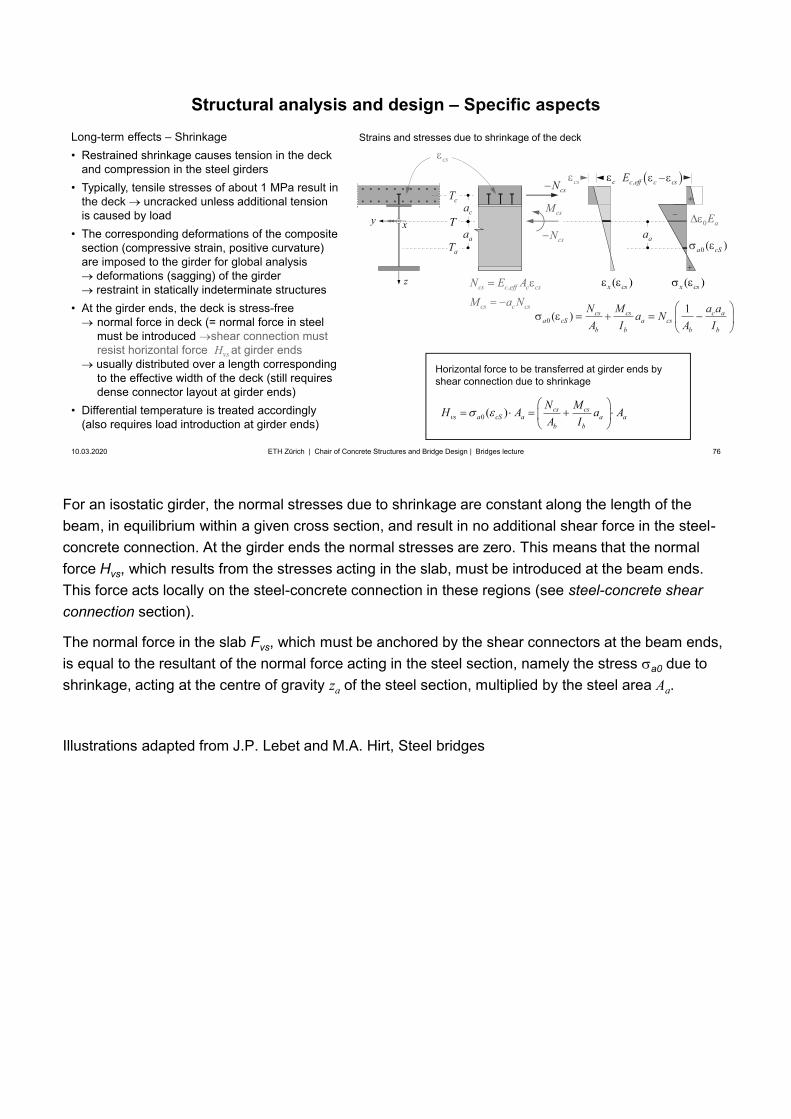
For an isostatic girder, the normal stresses due to shrinkage are constant along the length of the beam, in equilibrium within a given cross section, and result in no additional shear force in the steel-concrete connection. At the girder ends the normal stresses are zero. This means that the normal force Hvs, which results from the stresses acting in the slab, must be introduced at the beam ends. This force acts locally on the steel-concrete connection in these regions (see steel-concrete shear connection section).
The normal force in the slab Fvs, which must be anchored by the shear connectors at the beam ends, is equal to the resultant of the normal force acting in the steel section, namely the stress a0 due to shrinkage, acting at the centre of gravity za of the steel section, multiplied by the steel area Aa.
Illustrations adapted from J.P. Lebet and M.A. Hirt, Steel bridges
76
Horizontal force to be transferred at girder ends by shear connection due to shrinkage
Structural analysis and design – Specific aspects
10.03.2020 76ETH Zürich | Chair of Concrete Structures and Bridge Design | Bridges lecture
Long-term effects – Shrinkage• Restrained shrinkage causes tension in the deck
and compression in the steel girders• Typically, tensile stresses of about 1 MPa result in
the deck uncracked unless additional tensionis caused by load
• The corresponding deformations of the compositesection (compressive strain, positive curvature)are imposed to the girder for global analysis
deformations (sagging) of the girderrestraint in statically indeterminate structures
• At the girder ends, the deck is stress-freenormal force in deck (= normal force in steelmust be introduced shear connection must resist horizontal force Hvs at girder endsusually distributed over a length correspondingto the effective width of the deck (still requiresdense connector layout at girder ends)
• Differential temperature is treated accordingly(also requires load introduction at girder ends)
0 ( ) cs csvs a cS a a a
b b
N MH A a AA I
z
xyca
csN
csN
csM
aT
cT
T
cs
,cs c eff c cs
cs c cs
N E A
M a N
aa
01( ) cs cs c a
a cS a csb b b b
N M a aa NA I A I
Strains and stresses due to shrinkage of the deck
( )x cs( )x cs
cs ,c eff c csEc
0 aEaa
0 ( )a cS
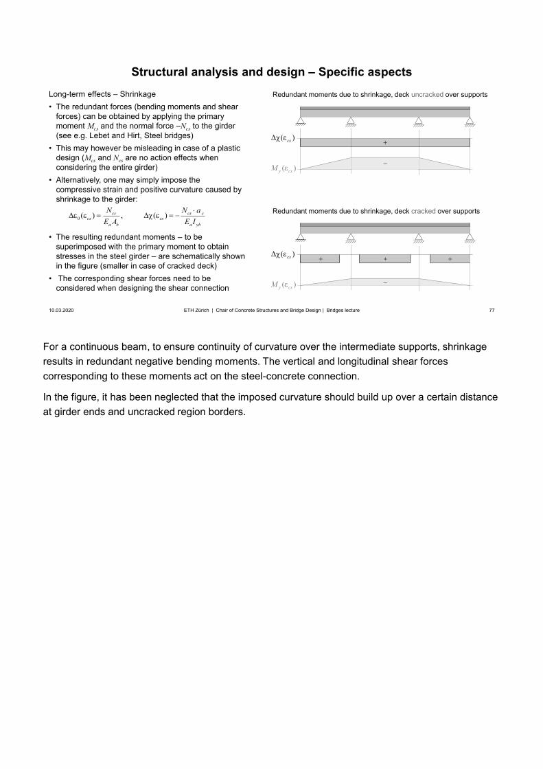
For a continuous beam, to ensure continuity of curvature over the intermediate supports, shrinkage results in redundant negative bending moments. The vertical and longitudinal shear forces corresponding to these moments act on the steel-concrete connection.
In the figure, it has been neglected that the imposed curvature should build up over a certain distance at girder ends and uncracked region borders.
77
Structural analysis and design – Specific aspects
10.03.2020 77ETH Zürich | Chair of Concrete Structures and Bridge Design | Bridges lecture
Long-term effects – Shrinkage• The redundant forces (bending moments and shear
forces) can be obtained by applying the primarymoment Mcs and the normal force –Ncs to the girder(see e.g. Lebet and Hirt, Steel bridges)
• This may however be misleading in case of a plasticdesign (Mcs and Ncs are no action effects whenconsidering the entire girder)
• Alternatively, one may simply impose thecompressive strain and positive curvature caused byshrinkage to the girder:
• The resulting redundant moments – to besuperimposed with the primary moment to obtainstresses in the steel girder – are schematically shownin the figure (smaller in case of cracked deck)
• The corresponding shear forces need to beconsidered when designing the shear connection
Redundant moments due to shrinkage, deck uncracked over supports
0 ( ) , ( )cs cs ccs cs
a b a yb
N N aE A E I
( )cs
( )y csM
Redundant moments due to shrinkage, deck cracked over supports
( )cs
( )y csM
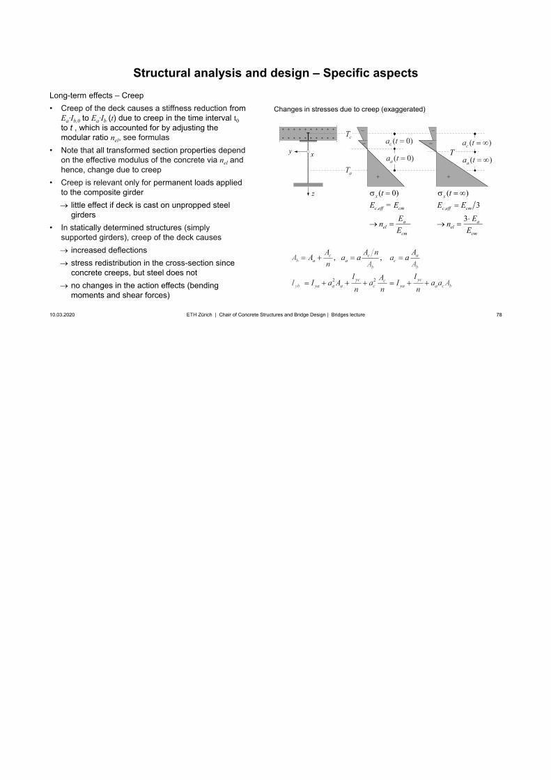
78
Structural analysis and design – Specific aspects
10.03.2020 78ETH Zürich | Chair of Concrete Structures and Bridge Design | Bridges lecture
Long-term effects – Creep• Creep of the deck causes a stiffness reduction from
Εa·Ib,0 to Εa·Ib (t) due to creep in the time interval t0to t , which is accounted for by adjusting themodular ratio nel, see formulas
• Note that all transformed section properties dependon the effective modulus of the concrete via nel andhence, change due to creep
• Creep is relevant only for permanent loads appliedto the composite girder
little effect if deck is cast on unpropped steelgirders
• In statically determined structures (simplysupported girders), creep of the deck causes
increased deflectionsstress redistribution in the cross-section sinceconcrete creeps, but steel does notno changes in the action effects (bendingmoments and shear forces)
Changes in stresses due to creep (exaggerated)
2 2
, , aa a
ya ba
c ccb
yc yca ya
b b
bcc
cay
AA aA
A
A A n aan
I IAa aI a I an
A
n
aA
I An
z
xy
aT
cT
T
,c eff cm
ael
cm
E = E
En
E
( 0)x t ( )x t
, 3
3c eff cm
ael
cm
E E
En
E
( 0)aa t
( 0)ca t
( )aa t
( )ca t
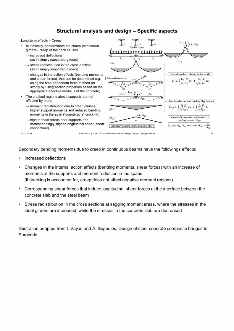
Secondary bending moments due to creep in continuous beams have the followings effects:
• Increased deflections
• Changes in the internal action effects (bending moments, shear forces) with an increase ofmoments at the supports and moment reduction in the spans(if cracking is accounted for, creep does not affect negative moment regions)
• Corresponding shear forces that induce longitudinal shear forces at the interface between theconcrete slab and the steel beam
• Stress redistribution in the cross sections at sagging moment areas, where the stresses in thesteel girders are increased, while the stresses in the concrete slab are decreased
Illustration adapted from I. Vayas and A. Iliopoulos, Design of steel-concrete composite bridges to Eurocode
79
Structural analysis and design – Specific aspects
10.03.2020 79ETH Zürich | Chair of Concrete Structures and Bridge Design | Bridges lecture
Long-term effects – Creep• In statically indeterminate structures (continuous
girders), creep of the deck causesincreased deflections(as in simply supported girders)stress redistribution in the cross-section(as in simply supported girders)changes in the action effects (bending moments and shear forces), that can be determined e.g. using the time-dependent force method (or simply by using section properties based on the appropriate effective modulus of the concrete)
• The cracked regions above supports are notaffected by creep
moment redistribution due to creep causeshigher support moments and reduced bending moments in the span (“counteracts” cracking) higher shear forces near supports andcorrespondingly, higher longitudinal shear (shear connection!)
80
Superstructure / Girder bridges
10.03.2020 80
Design and erectionSteel and steel-concrete composite girders
Construction and erection
ETH Zürich | Chair of Concrete Structures and Bridge Design | Bridges lecture
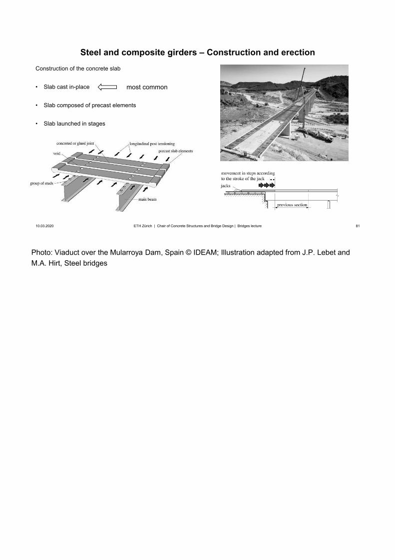
Photo: Viaduct over the Mularroya Dam, Spain © IDEAM; Illustration adapted from J.P. Lebet and M.A. Hirt, Steel bridges
81
Steel and composite girders – Construction and erection
10.03.2020 81ETH Zürich | Chair of Concrete Structures and Bridge Design | Bridges lecture
Construction of the concrete slab
• Slab cast in-place
• Slab composed of precast elements
• Slab launched in stages
most common
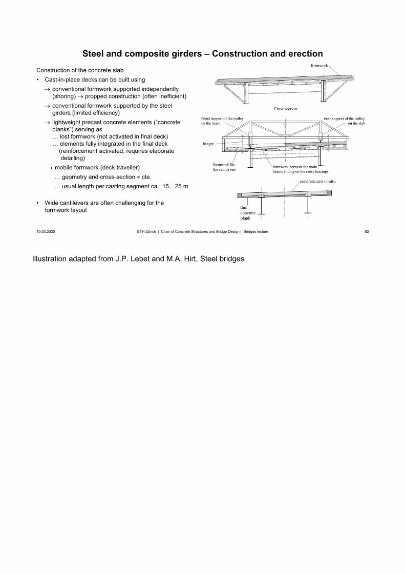
Illustration adapted from J.P. Lebet and M.A. Hirt, Steel bridges
82
Steel and composite girders – Construction and erection
10.03.2020 82ETH Zürich | Chair of Concrete Structures and Bridge Design | Bridges lecture
Construction of the concrete slab• Cast-in-place decks can be built using
conventional formwork supported independently(shoring) propped construction (often inefficient)conventional formwork supported by the steel girders (limited efficiency)lightweight precast concrete elements (“concrete planks”) serving as … lost formwork (not activated in final deck) … elements fully integrated in the final deck
(reinforcement activated, requires elaboratedetailing)
mobile formwork (deck traveller)… geometry and cross-section cte.… usual length per casting segment ca. 15…25 m
• Wide cantilevers are often challenging for theformwork layout
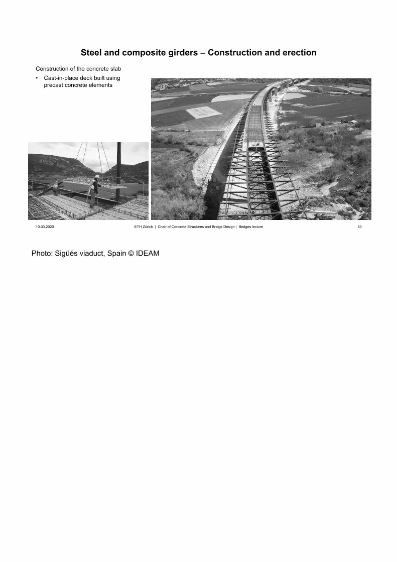
Photo: Sigüés viaduct, Spain © IDEAM
83
Steel and composite girders – Construction and erection
10.03.2020 83ETH Zürich | Chair of Concrete Structures and Bridge Design | Bridges lecture
Construction of the concrete slab• Cast-in-place deck built using
precast concrete elements
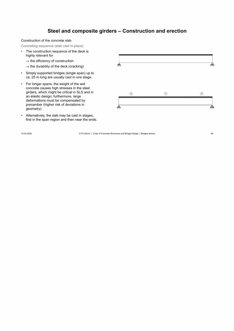
84
Steel and composite girders – Construction and erection
10.03.2020 84ETH Zürich | Chair of Concrete Structures and Bridge Design | Bridges lecture
Construction of the concrete slabConcreting sequence (slab cast in-place)• The construction sequence of the deck is
highly relevant forthe efficiency of constructionthe durability of the deck (cracking)
• Simply supported bridges (single span) up toca. 25 m long are usually cast in one stage.
• For longer spans, the weight of the wetconcrete causes high stresses in the steelgirders, which might be critical in SLS and inan elastic design; furthermore, largedeformations must be compensated byprecamber (higher risk of deviations ingeometry).
• Alternatively, the slab may be cast in stages,first in the span region and then near the ends.
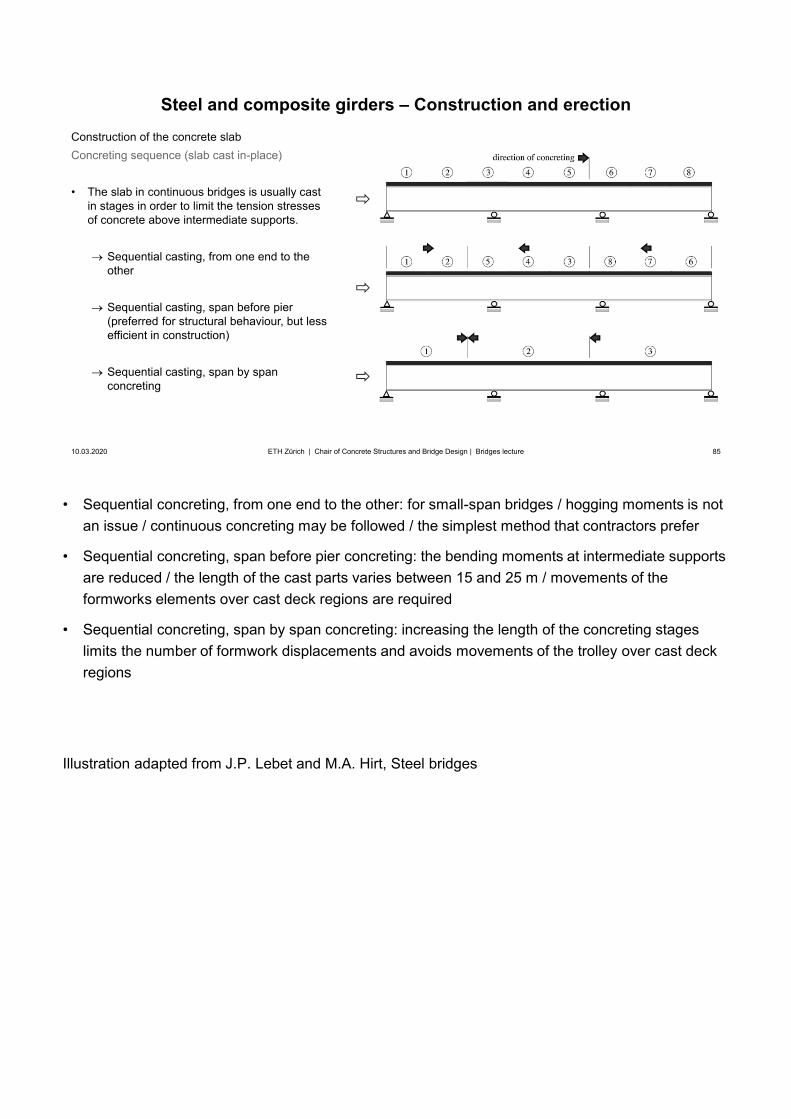
• Sequential concreting, from one end to the other: for small-span bridges / hogging moments is notan issue / continuous concreting may be followed / the simplest method that contractors prefer
• Sequential concreting, span before pier concreting: the bending moments at intermediate supportsare reduced / the length of the cast parts varies between 15 and 25 m / movements of theformworks elements over cast deck regions are required
• Sequential concreting, span by span concreting: increasing the length of the concreting stageslimits the number of formwork displacements and avoids movements of the trolley over cast deckregions
Illustration adapted from J.P. Lebet and M.A. Hirt, Steel bridges
85
Steel and composite girders – Construction and erection
10.03.2020 85ETH Zürich | Chair of Concrete Structures and Bridge Design | Bridges lecture
Construction of the concrete slabConcreting sequence (slab cast in-place)
• The slab in continuous bridges is usually castin stages in order to limit the tension stressesof concrete above intermediate supports.
Sequential casting, from one end to the other
Sequential casting, span before pier (preferred for structural behaviour, but less efficient in construction)
Sequential casting, span by span concreting
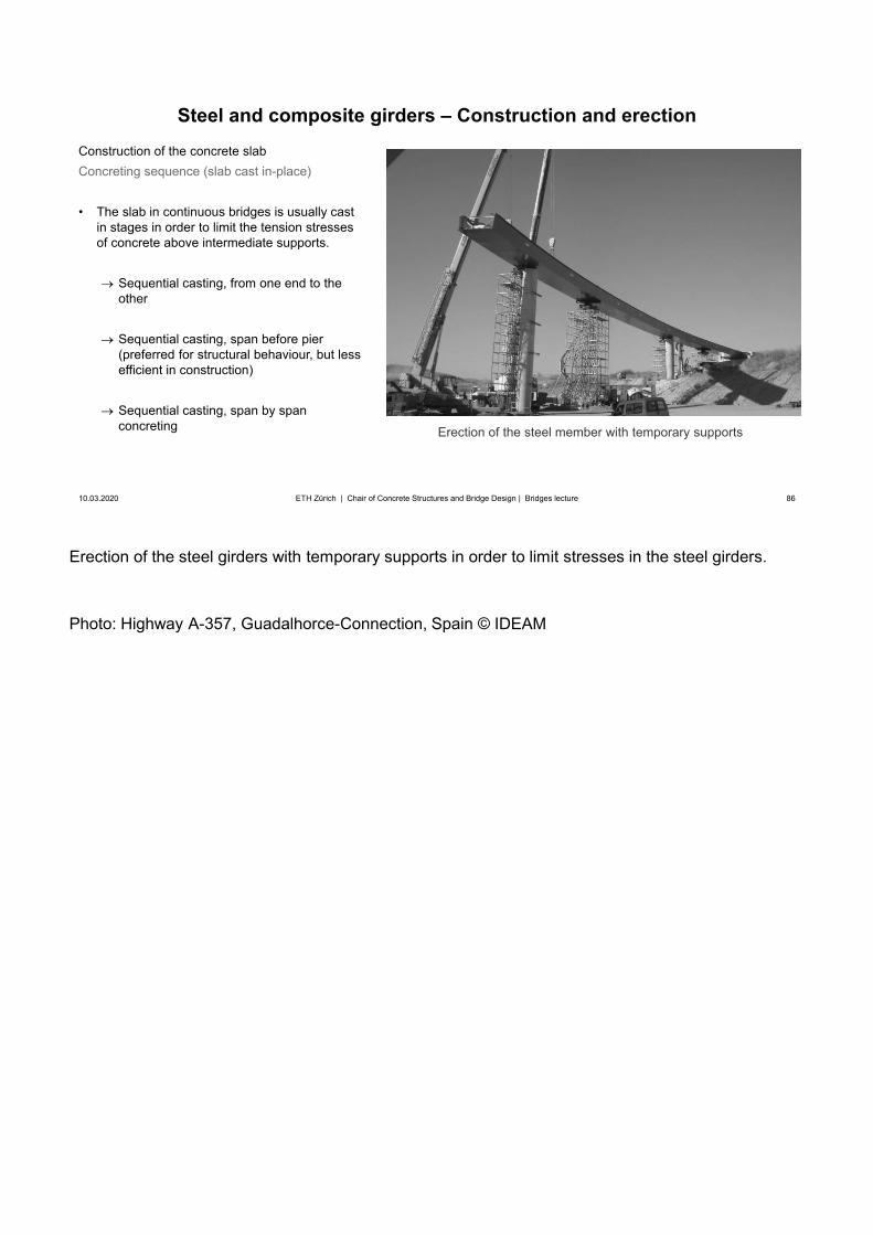
Erection of the steel girders with temporary supports in order to limit stresses in the steel girders.
Photo: Highway A-357, Guadalhorce-Connection, Spain © IDEAM
86
Steel and composite girders – Construction and erection
10.03.2020 86ETH Zürich | Chair of Concrete Structures and Bridge Design | Bridges lecture
Construction of the concrete slabConcreting sequence (slab cast in-place)
• The slab in continuous bridges is usually castin stages in order to limit the tension stressesof concrete above intermediate supports.
Sequential casting, from one end to the other
Sequential casting, span before pier (preferred for structural behaviour, but less efficient in construction)
Sequential casting, span by span concreting Erection of the steel member with temporary supports
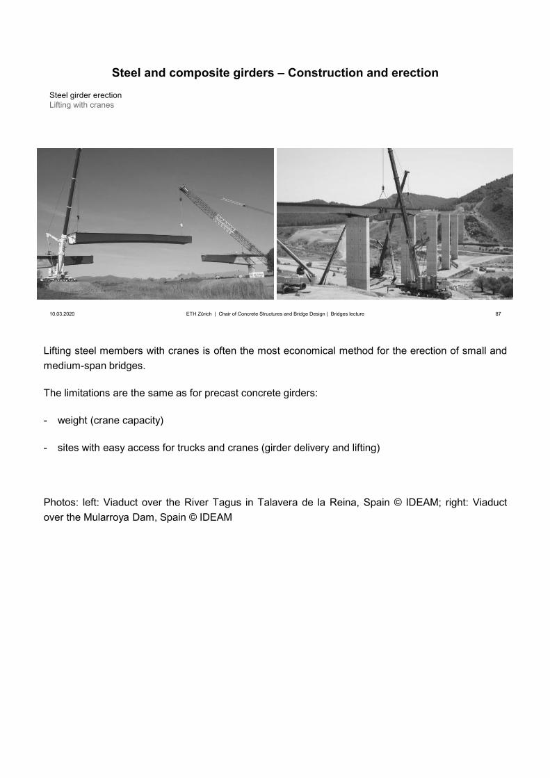
Lifting steel members with cranes is often the most economical method for the erection of small andmedium-span bridges.
The limitations are the same as for precast concrete girders:
- weight (crane capacity)
- sites with easy access for trucks and cranes (girder delivery and lifting)
Photos: left: Viaduct over the River Tagus in Talavera de la Reina, Spain © IDEAM; right: Viaductover the Mularroya Dam, Spain © IDEAM
87
10.03.2020 87ETH Zürich | Chair of Concrete Structures and Bridge Design | Bridges lecture
Steel girder erectionLifting with cranes
Steel and composite girders – Construction and erection
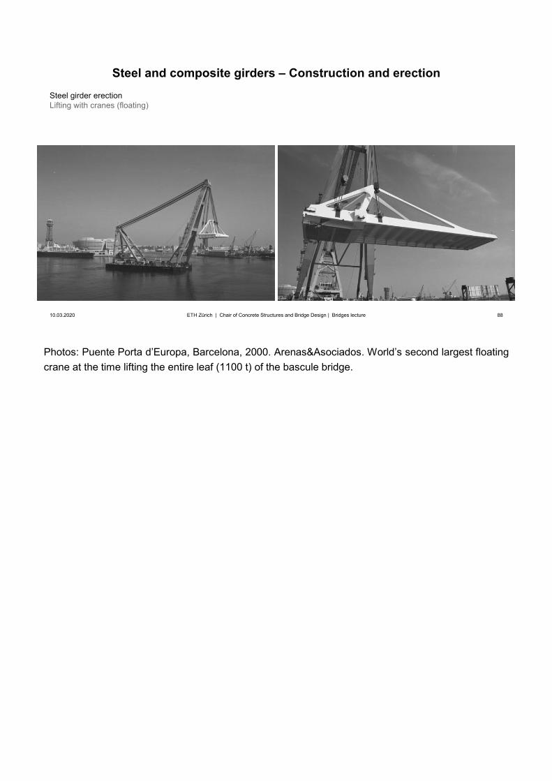
Photos: Puente Porta d’Europa, Barcelona, 2000. Arenas&Asociados. World’s second largest floatingcrane at the time lifting the entire leaf (1100 t) of the bascule bridge.
88
10.03.2020 88ETH Zürich | Chair of Concrete Structures and Bridge Design | Bridges lecture
Steel girder erectionLifting with cranes (floating)
Steel and composite girders – Construction and erection
89
10.03.2020 89ETH Zürich | Chair of Concrete Structures and Bridge Design | Bridges lecture
Steel and composite girders – Construction and erection
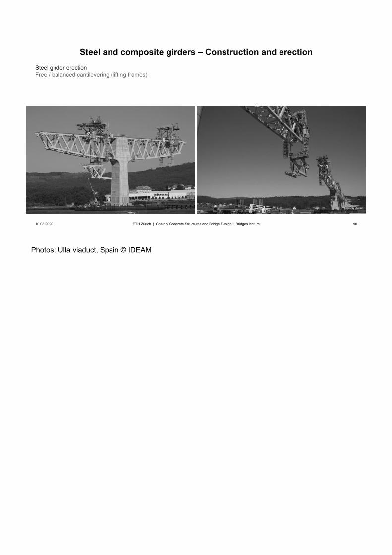
Photos: Ulla viaduct, Spain © IDEAM
90
10.03.2020 90ETH Zürich | Chair of Concrete Structures and Bridge Design | Bridges lecture
Steel girder erectionFree / balanced cantilevering (lifting frames)
Steel and composite girders – Construction and erection

Photo: https://www.financialexpress.com/
Video adapted from https://www.youtube.com/watch?v=MbpeJ_3XH9c
91
10.03.2020 91ETH Zürich | Chair of Concrete Structures and Bridge Design | Bridges lecture
Steel girder erectionLaunching
Steel and composite girders – Construction and erection
New Quaibrücke Zürich, Fietz+Leuthold AG (1984). Replacement of existing bridge by transverselaunching.
Figures: R. Heierli et al., Quaibrücke Zürich, Schweizer Ingenieur und Architekt, Vol. 103 (1985), No.10, pp. 183-195
Photos: e-pics.ethz.ch
92
10.03.2020 92ETH Zürich | Chair of Concrete Structures and Bridge Design | Bridges lecture
Steel / composite girder erectionTransverse launching (shifting)• Example: Replacement of Quaibrücke Zürich, 1984• New bridge: Steel-concrete composite, l=121 m, spans
22.6+24.8+26.5+24.8+22.6 m, width 30.5 m• Appearance had to mimic old bridge (Volksinitiative), but
only 4 instead of 8 girders, ca. 50% steel weight)
Steel and composite girders – Construction and erection
New bridge under construction (downstream of old bridge)
Figures: R. Heierli et al., Quaibrücke Zürich, Schweizer Ingenieur und Architekt, Vol. 103 (1985), No.10, pp. 183-195
Photos: e-pics.ethz.ch
93
10.03.2020 93ETH Zürich | Chair of Concrete Structures and Bridge Design | Bridges lecture
Steel / composite girder erectionTransverse launching (shifting)• Old and new bridges connected for launching,
total weight launched 7’800 t• Bridge closed to traffic:
Fri 16.3.1984, 21:00 to Mon 19.3.1984, 06:00• Launching: Sat 17.3.1984, 00:00-15:15 h
(net 14 h launching time)
Steel and composite girders – Construction and erection
temporary substructure: old bridge after launching
temporary substructure:new bridge before launching
existing piers(strengthened, but maintained)
launching direction
new bridge: 30.50 mold bridge: 28.50 m
weight 4070 tweight 3720 t
Photos: e-pics.ethz.ch
94
10.03.2020 94ETH Zürich | Chair of Concrete Structures and Bridge Design | Bridges lecture
Steel / composite girder erectionTransverse launching (shifting)
Steel and composite girders – Construction and erection
New bridge and launching tracks (almost) ready for launchingNew bridge and temporary substructure in lake under construction
Photos: e-pics.ethz.ch
95
10.03.2020 95ETH Zürich | Chair of Concrete Structures and Bridge Design | Bridges lecture
Steel / composite girder erectionTransverse launching (shifting)
Steel and composite girders – Construction and erection
Demolishment of old bridgeTwo bridges travelling towards the lake


![AASHTO - LRFD [Design Example for Steel Girder Superstructure Bridge - 2003]](https://img.pdfslide.us/doc/110x75/54faee334a79590b398b4fd6/aashto-lrfd-design-example-for-steel-girder-superstructure-bridge-2003.jpg)