Embed Size (px)
Citation preview
Fatigue Design for Steel Bridges
Load Induced Fatigue Design for Steel Bridgesaccording to the AASHTO
Going to cover...
• 1. Basic fundamentals of Fracture Mechanics(Crack initiation)
• 2. Fatigue Strength
• 3. Fatigue Design According to the AASHTO
• 4. Example (Load-Induced Design)
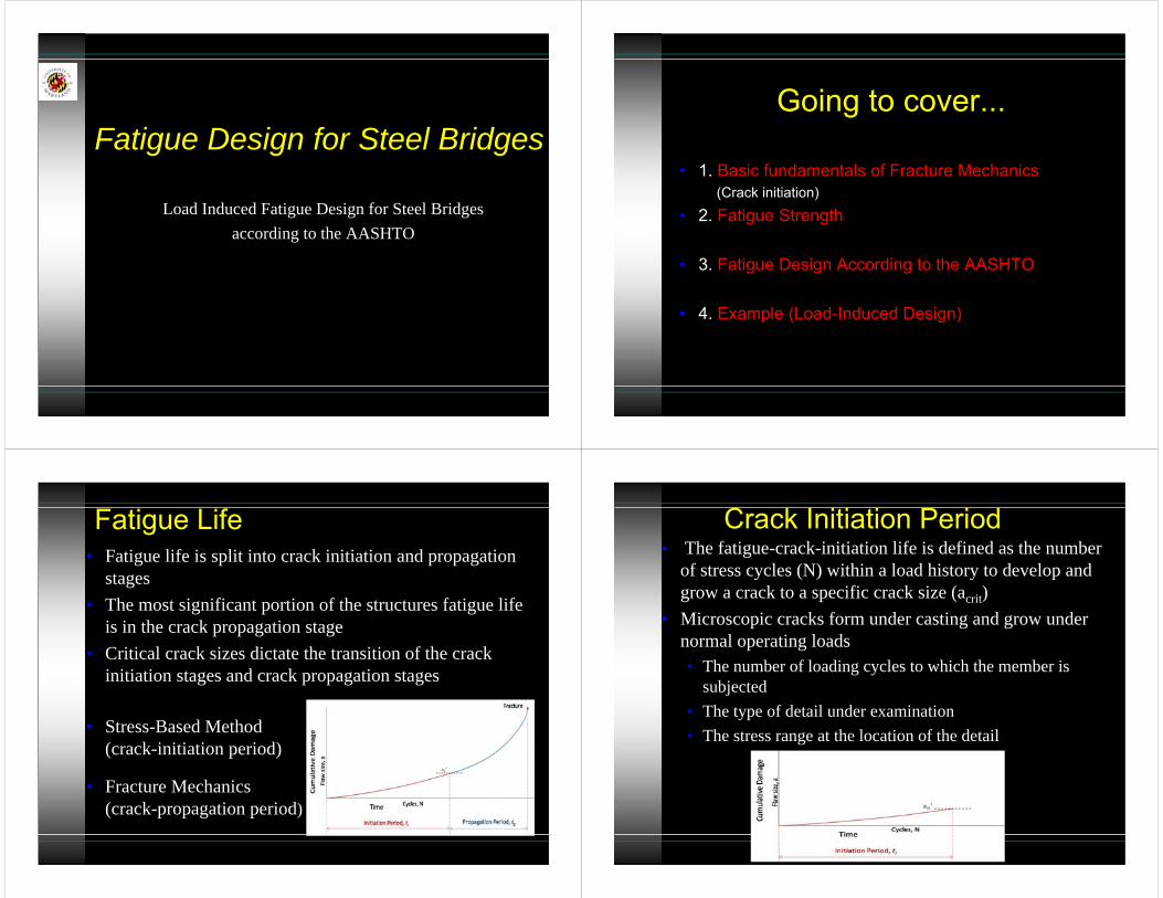
Fatigue Life• Fatigue life is split into crack initiation and propagation
stages• The most significant portion of the structures fatigue life
is in the crack propagation stage• Critical crack sizes dictate the transition of the crack
initiation stages and crack propagation stages
• Stress-Based Method(crack-initiation period)
• Fracture Mechanics(crack-propagation period)
• The fatigue-crack-initiation life is defined as the number of stress cycles (N) within a load history to develop and grow a crack to a specific crack size (acrit)
• Microscopic cracks form under casting and grow under normal operating loads• The number of loading cycles to which the member is
subjected• The type of detail under examination • The stress range at the location of the detail
Crack Initiation Period
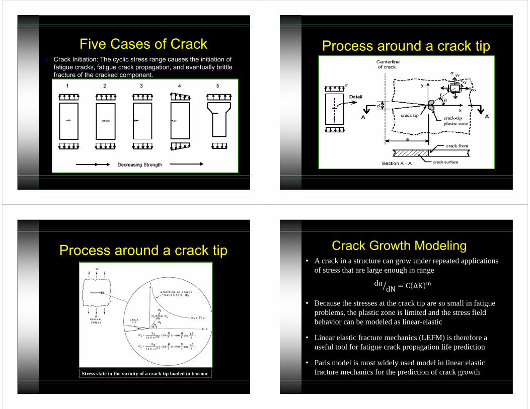
Five Cases of Crack• Crack Initiation: The cyclic stress range causes the initiation of
fatigue cracks, fatigue crack propagation, and eventually brittle fracture of the cracked component.
Process around a crack tip
Process around a crack tip
Stress state in the vicinity of a crack tip loaded in tension
• A crack in a structure can grow under repeated applications of stress that are large enough in ranged dN C ∆K
• Because the stresses at the crack tip are so small in fatigue problems, the plastic zone is limited and the stress field behavior can be modeled as linear-elastic
• Linear elastic fracture mechanics (LEFM) is therefore a useful tool for fatigue crack propagation life prediction
• Paris model is most widely used model in linear elastic fracture mechanics for the prediction of crack growth
Crack Growth Modeling
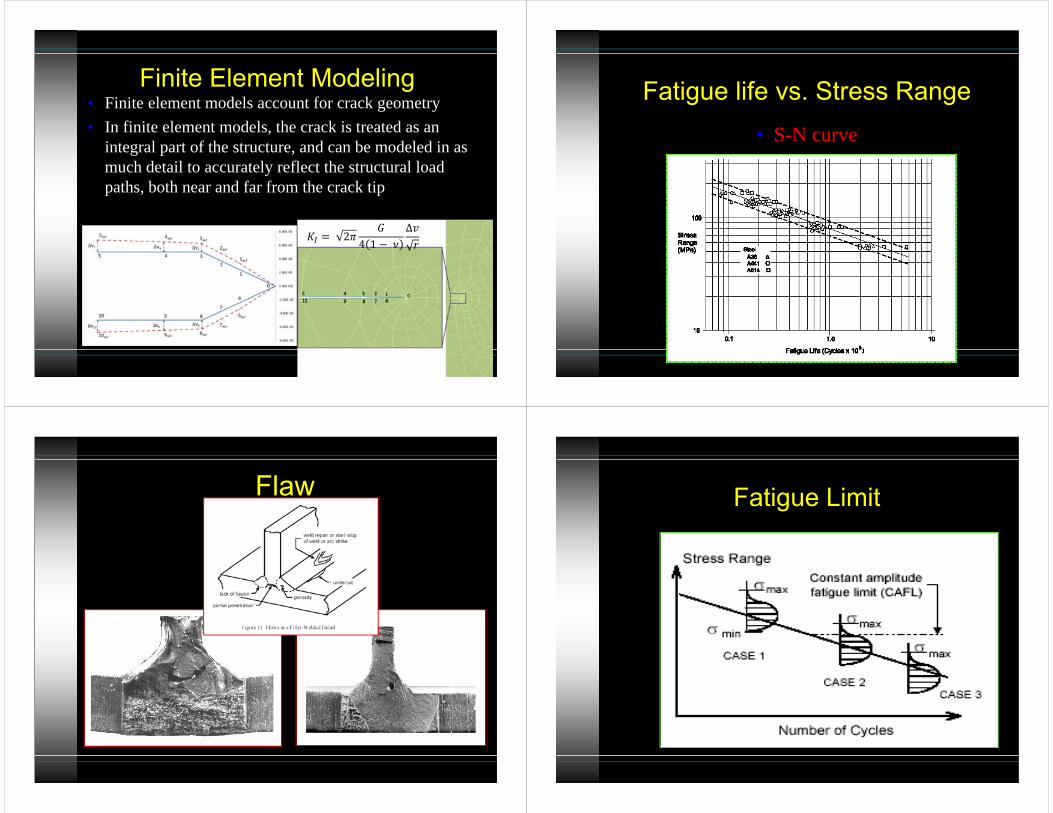
• Finite element models account for crack geometry • In finite element models, the crack is treated as an
integral part of the structure, and can be modeled in as much detail to accurately reflect the structural load paths, both near and far from the crack tip
Finite Element Modeling
2 4 1 ∆
Fatigue life vs. Stress Range• S-N curve
Flaw Fatigue Limit
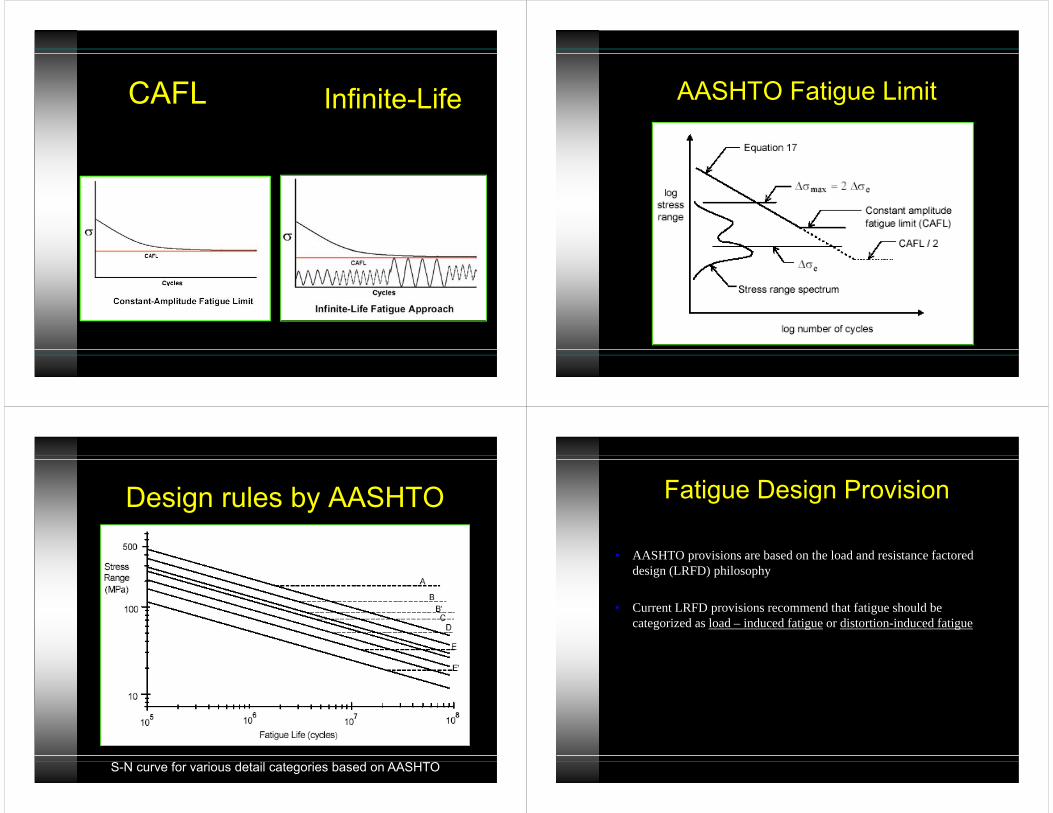
Infinite-LifeCAFL AASHTO Fatigue Limit
Design rules by AASHTO
S-N curve for various detail categories based on AASHTO
Fatigue Design Provision
• AASHTO provisions are based on the load and resistance factored design (LRFD) philosophy
• Current LRFD provisions recommend that fatigue should be categorized as load – induced fatigue or distortion-induced fatigue
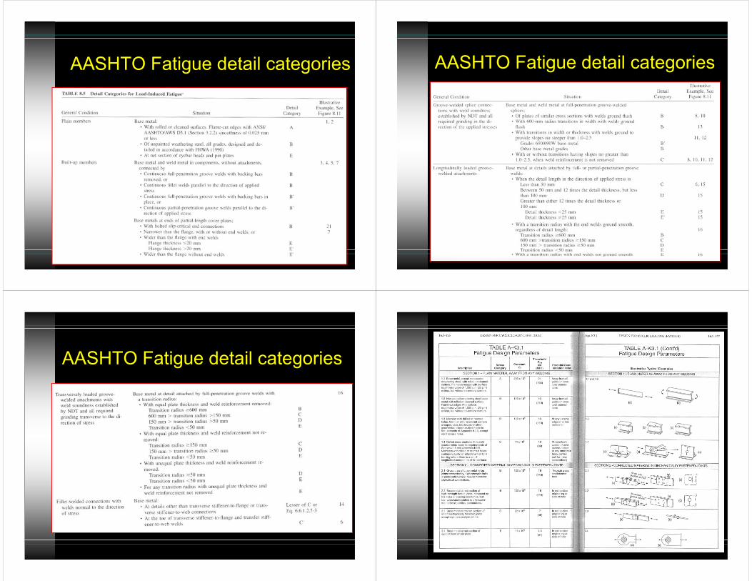
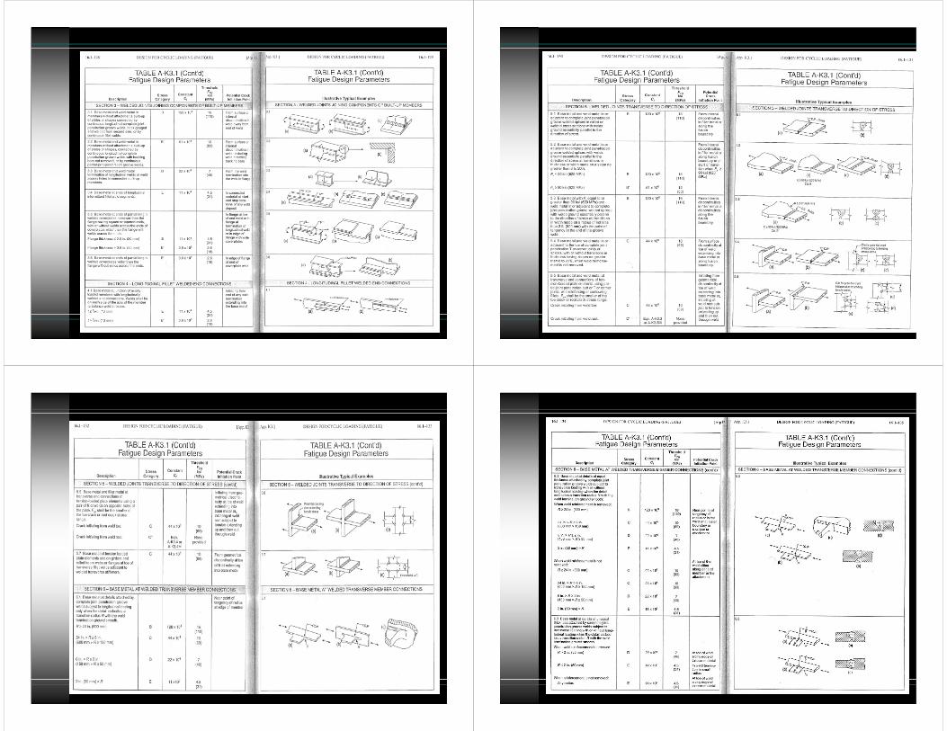
AASHTO Fatigue detail categories AASHTO Fatigue detail categories
AASHTO Fatigue detail categories
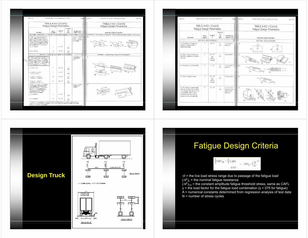
Design Truck
Fatigue Design Criteria
∆f = the live load stress range due to passage of the fatigue load(∆F)n = the nominal fatigue resistance(∆F)TH = the constant amplitude fatigue threshold stress, same as CAFLγ = the load factor for the fatigue load combination (γ = 075 for fatigue)A = numerical constants determined from regression analysis of test dataN = number of stress cycles
N
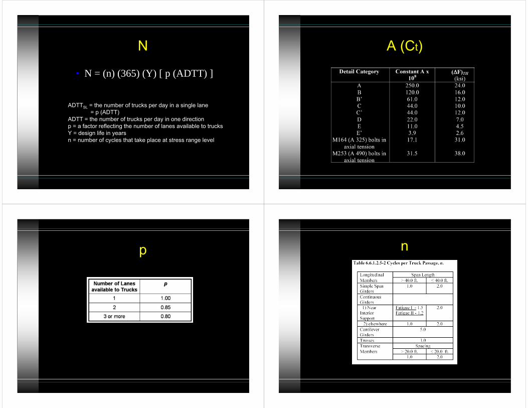
• N = (n) (365) (Y) [ p (ADTT) ]
ADTTSL = the number of trucks per day in a single lane= p (ADTT)
ADTT = the number of trucks per day in one directionp = a factor reflecting the number of lanes available to trucksY = design life in yearsn = number of cycles that take place at stress range level
A (Ct)
p n
ADTT and ADTTSL
• In the absence of better information ADTTSL can be estimated as(ADTT)SL = p x ADTT
• ADTT = number of trucks per day in one direction averaged over the design life
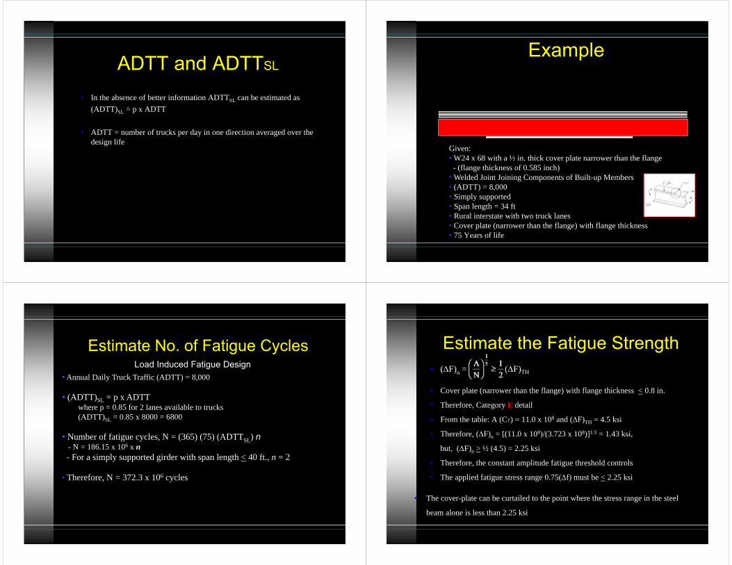
Example
Given:• W24 x 68 with a ½ in. thick cover plate narrower than the flange- (flange thickness of 0.585 inch)
• Welded Joint Joining Components of Built-up Members• (ADTT) = 8,000• Simply supported• Span length = 34 ft• Rural interstate with two truck lanes• Cover plate (narrower than the flange) with flange thickness• 75 Years of life
Estimate No. of Fatigue CyclesLoad Induced Fatigue Design
• Annual Daily Truck Traffic (ADTT) = 8,000
• (ADTT)SL = p x ADTTwhere p = 0.85 for 2 lanes available to trucks(ADTT)SL = 0.85 x 8000 = 6800
• Number of fatigue cycles, N = (365) (75) (ADTTSL) n- N = 186.15 x 10⁶ x n- For a simply supported girder with span length < 40 ft., n = 2
• Therefore, N = 372.3 x 10⁶ cycles
Estimate the Fatigue Strength• (F)n = (F)TH
• Cover plate (narrower than the flange) with flange thickness < 0.8 in.
• Therefore, Category E detail
• From the table: A (CT) = 11.0 x 10⁸ and (F)TH = 4.5 ksi
• Therefore, (F)n = [(11.0 x 10⁸)/(3.723 x 108)]1/3 = 1.43 ksi,
but, (F)n > ½ (4.5) = 2.25 ksi
• Therefore, the constant amplitude fatigue threshold controls
• The applied fatigue stress range 0.75(f) must be < 2.25 ksi
• The cover-plate can be curtailed to the point where the stress range in the steel
beam alone is less than 2.25 ksi