Embed Size (px)
Citation preview
DUA1715-0AAA02.book Page 1 Wednesday, March 23, 2005 11:17 AM
SuperStack® 4Switch 5500 FamilyGetting Started Guide
http://www.3com.com/
Part No. DUA1715-0AAA02Published April 2005
Switch 5500-SI 28-Port (3CR17151-91)Switch 5500-SI 52-Port (3CR17152-91)
Switch 5500-EI 28-Port (3CR17161-91)Switch 5500-EI 52-Port (3CR17162-91)
DUA1715-0AAA02.book Page 2 Wednesday, March 23, 2005 11:17 AM
3Com Corporation350 Campus Drive Marlborough, MA 01752-3064
Copyright © 2005, 3Com Corporation. All rights reserved. No part of this documentation may be reproduced in any form or by any means or used to make any derivative work (such as translation, transformation, or adaptation) without written permission from 3Com Corporation.
3Com Corporation reserves the right to revise this documentation and to make changes in content from time to time without obligation on the part of 3Com Corporation to provide notification of such revision or change.
3Com Corporation provides this documentation without warranty, term, or condition of any kind, either implied or expressed, including, but not limited to, the implied warranties, terms or conditions of merchantability, satisfactory quality, and fitness for a particular purpose. 3Com may make improvements or changes in the product(s) and/or the program(s) described in this documentation at any time.
If there is any software on removable media described in this documentation, it is furnished under a license agreement included with the product as a separate document, in the hard copy documentation, or on the removable media in a directory file named LICENSE.TXT or !LICENSE.TXT. If you are unable to locate a copy, please contact 3Com and a copy will be provided to you.
UNITED STATES GOVERNMENT LEGEND
If you are a United States government agency, then this documentation and the software described herein are provided to you subject to the following:
All technical data and computer software are commercial in nature and developed solely at private expense. Software is delivered as “Commercial Computer Software” as defined in DFARS 252.227-7014 (June 1995) or as a “commercial item” as defined in FAR 2.101(a) and as such is provided with only such rights as are provided in 3Com’s standard commercial license for the Software. Technical data is provided with limited rights only as provided in DFAR 252.227-7015 (Nov 1995) or FAR 52.227-14 (June 1987), whichever is applicable. You agree not to remove or deface any portion of any legend provided on any licensed program or documentation contained in, or delivered to you in conjunction with, this User Guide.
Unless otherwise indicated, 3Com registered trademarks are registered in the United States and may or may not be registered in other countries.
3Com, the 3Com logo and SuperStack are registered trademarks of 3Com Corporation.
Intel and Pentium are registered trademarks of Intel Corporation. Microsoft, MS-DOS, Windows, and Windows NT are registered trademarks of Microsoft Corporation. Novell and NetWare are registered trademarks of Novell, Inc. UNIX is a registered trademark in the United States and other countries, licensed exclusively through X/Open Company, Ltd.
IEEE and 802 are registered trademarks of the Institute of Electrical and Electronics Engineers, Inc.
Netscape Navigator is a registered trademark of Netscape Communications.
JavaScript is a trademark of Sun Microsystems.
All other company and product names may be trademarks of the respective companies with which they are associated.
ENVIRONMENTAL STATEMENT
It is the policy of 3Com Corporation to be environmentally-friendly in all operations. To uphold our policy, we are committed to:
Establishing environmental performance standards that comply with national legislation and regulations.
Conserving energy, materials and natural resources in all operations.
Reducing the waste generated by all operations. Ensuring that all waste conforms to recognized environmental standards. Maximizing the recyclable and reusable content of all products.
Ensuring that all products can be recycled, reused and disposed of safely.
Ensuring that all products are labelled according to recognized environmental standards.
Improving our environmental record on a continual basis.
End of Life Statement
3Com processes allow for the recovery, reclamation and safe disposal of all end-of-life electronic components.
Regulated Materials Statement
3Com products do not contain any hazardous or ozone-depleting material.
Environmental Statement about the Documentation
The documentation for this product is printed on paper that comes from sustainable, managed forests; it is fully biodegradable and recyclable, and is completely chlorine-free. The varnish is environmentally-friendly, and the inks are vegetable-based with a low heavy-metal content.
ENCRYPTION
This product contains encryption and may require U.S. and/or local government authorization prior to export or import to another country.
DUA1715-0AAA02.book Page 3 Wednesday, March 23, 2005 11:17 AM
CONTENTS
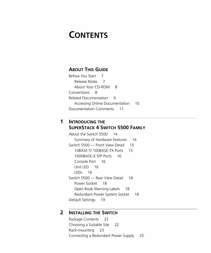
ABOUT THIS GUIDE
Before You Start 7Release Notes 7About Your CD-ROM 8
Conventions 8Related Documentation 9
Accessing Online Documentation 10Documentation Comments 11
1 INTRODUCING THE SUPERSTACK 4 SWITCH 5500 FAMILY
About the Switch 5500 14Summary of Hardware Features 14
Switch 5500 — Front View Detail 1510BASE-T/ 100BASE-TX Ports 151000BASE-X SFP Ports 16Console Port 16Unit LED 16LEDs 16
Switch 5500 — Rear View Detail 18Power Socket 18Open Book Warning Labels 18Redundant Power System Socket 18
Default Settings 19
2 INSTALLING THE SWITCH
Package Contents 22Choosing a Suitable Site 22Rack-mounting 23Connecting a Redundant Power Supply 25
DUA1715-0AAA02.book Page 4 Wednesday, March 23, 2005 11:17 AM
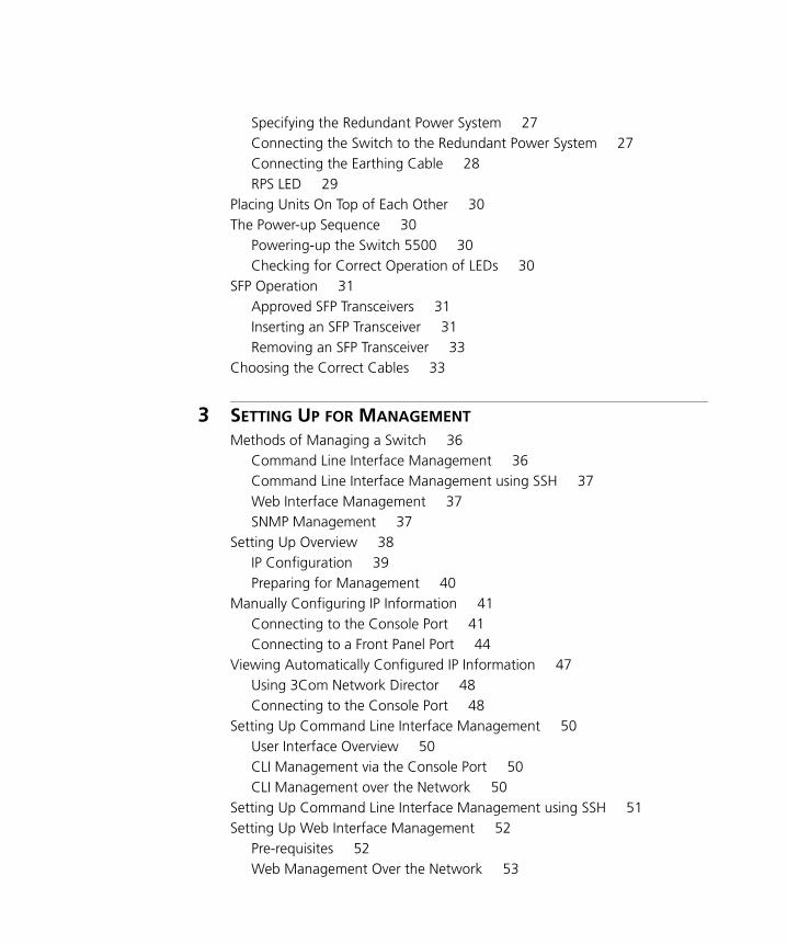
Specifying the Redundant Power System 27Connecting the Switch to the Redundant Power System 27Connecting the Earthing Cable 28RPS LED 29
Placing Units On Top of Each Other 30The Power-up Sequence 30
Powering-up the Switch 5500 30Checking for Correct Operation of LEDs 30
SFP Operation 31Approved SFP Transceivers 31Inserting an SFP Transceiver 31Removing an SFP Transceiver 33
Choosing the Correct Cables 33
3 SETTING UP FOR MANAGEMENT
Methods of Managing a Switch 36Command Line Interface Management 36Command Line Interface Management using SSH 37Web Interface Management 37SNMP Management 37
Setting Up Overview 38IP Configuration 39Preparing for Management 40
Manually Configuring IP Information 41Connecting to the Console Port 41Connecting to a Front Panel Port 44
Viewing Automatically Configured IP Information 47Using 3Com Network Director 48Connecting to the Console Port 48
Setting Up Command Line Interface Management 50User Interface Overview 50CLI Management via the Console Port 50CLI Management over the Network 50
Setting Up Command Line Interface Management using SSH 51Setting Up Web Interface Management 52
Pre-requisites 52Web Management Over the Network 53
DUA1715-0AAA02.book Page 5 Wednesday, March 23, 2005 11:17 AM
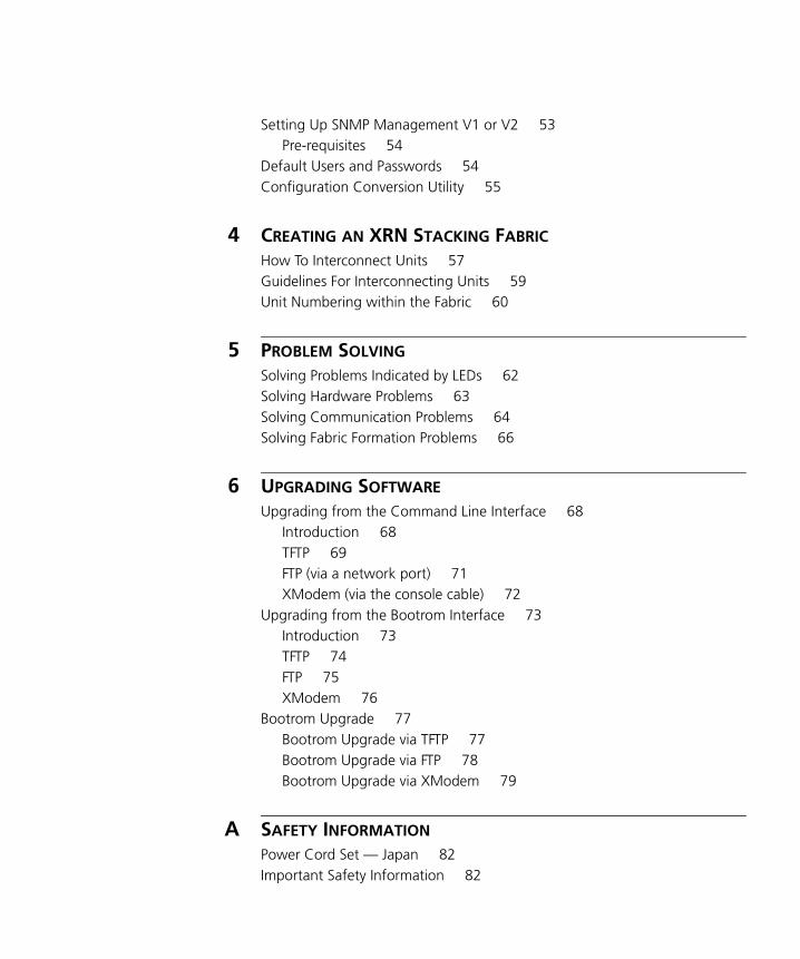
Setting Up SNMP Management V1 or V2 53Pre-requisites 54
Default Users and Passwords 54Configuration Conversion Utility 55
4 CREATING AN XRN STACKING FABRIC
How To Interconnect Units 57Guidelines For Interconnecting Units 59Unit Numbering within the Fabric 60
5 PROBLEM SOLVING
Solving Problems Indicated by LEDs 62Solving Hardware Problems 63Solving Communication Problems 64Solving Fabric Formation Problems 66
6 UPGRADING SOFTWARE
Upgrading from the Command Line Interface 68Introduction 68TFTP 69FTP (via a network port) 71XModem (via the console cable) 72
Upgrading from the Bootrom Interface 73Introduction 73TFTP 74FTP 75XModem 76
Bootrom Upgrade 77Bootrom Upgrade via TFTP 77Bootrom Upgrade via FTP 78Bootrom Upgrade via XModem 79
A SAFETY INFORMATION
Power Cord Set — Japan 82Important Safety Information 82
DUA1715-0AAA02.book Page 6 Wednesday, March 23, 2005 11:17 AM
L’information de Sécurité Importante 85Wichtige Sicherheitsinformationen 88Información de Seguridad Importante 90Importanti Informazioni di Sicurezza 93Ważne informacje o zabezpieczeniach 96
B PIN-OUTS
Null Modem Cable 101PC-AT Serial Cable 101Modem Cable 102Ethernet Port RJ-45 Pin Assignments 102
C TECHNICAL SPECIFICATIONS
Switch 5500-SI 105Switch 5500-EI 107RPS 108Earthing Lead 109
D OBTAINING SUPPORT FOR YOUR PRODUCT
Register Your Product 111Purchase Value-Added Services 111Troubleshoot Online 112Access Software Downloads 112Telephone Technical Support and Repair 112Contact Us 113
INDEX
REGULATORY NOTICES
DUA1715-0AAA02.book Page 7 Wednesday, March 23, 2005 11:17 AM
ABOUT THIS GUIDE
This guide provides all the information you need to install and use the following switches in their default state:
■ SuperStack® 4 Switch 5500-SI 28-Port (3CR17151-91)
■ SuperStack® 4 Switch 5500-SI 52-Port (3CR17152-91)
■ SuperStack® 4 Switch 5500-EI 28-Port (3CR17161-91)
■ SuperStack® 4 Switch 5500-EI 52-Port (3CR17162-91)
All procedures described in this guide apply to all models except where stated.
The guide is intended for use by network administrators who are responsible for installing and setting up network equipment; consequently, it assumes a basic working knowledge of LANs (Local Area Networks).
Before You Start This section contains information about the documents and CD-ROM that accompany your Switch 5500.
Release Notes The Release Notes provide important information about the current software release, including new features, modifications, and known problems. You should read the Release Notes before installing the Switch in your network.
If the information in the Release Notes differ from the information in this guide, follow the instructions in the Release Notes.
8 ABOUT THIS GUIDE
DUA1715-0AAA02.book Page 8 Wednesday, March 23, 2005 11:17 AM
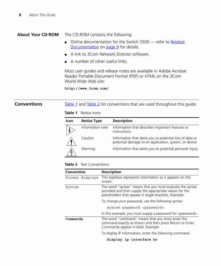
About Your CD-ROM The CD-ROM contains the following:
■ Online documentation for the Switch 5500 — refer to Related Documentation on page 9 for details.
■ A link to 3Com Network Director software.
■ A number of other useful links.
Most user guides and release notes are available in Adobe Acrobat Reader Portable Document Format (PDF) or HTML on the 3Com World Wide Web site:
http://www.3com.com/
Conventions Table 1 and Table 2 list conventions that are used throughout this guide.
Table 1 Notice Icons
Icon Notice Type Description
Information note Information that describes important features or instructions
Caution Information that alerts you to potential loss of data or potential damage to an application, system, or device
Warning Information that alerts you to potential personal injury
Table 2 Text Conventions
Convention DescriptionScreen displays This typeface represents information as it appears on the
screen.Syntax The word “syntax” means that you must evaluate the syntax
provided and then supply the appropriate values for the placeholders that appear in angle brackets. Example:
To change your password, use the following syntax:
system password <password>
In this example, you must supply a password for <password>.Commands The word “command” means that you must enter the
command exactly as shown and then press Return or Enter. Commands appear in bold. Example:
To display IP information, enter the following command:
display ip interface br
Related Documentation 9
DUA1715-0AAA02.book Page 9 Wednesday, March 23, 2005 11:17 AM
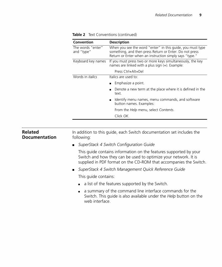
Related Documentation
In addition to this guide, each Switch documentation set includes the following:
■ SuperStack 4 Switch Configuration Guide
This guide contains information on the features supported by your Switch and how they can be used to optimize your network. It is supplied in PDF format on the CD-ROM that accompanies the Switch.
■ SuperStack 4 Switch Management Quick Reference Guide
This guide contains:
■ a list of the features supported by the Switch.
■ a summary of the command line interface commands for the Switch. This guide is also available under the Help button on the web interface.
The words “enter” and “type”
When you see the word “enter” in this guide, you must type something, and then press Return or Enter. Do not press Return or Enter when an instruction simply says “type.”
Keyboard key names If you must press two or more keys simultaneously, the key names are linked with a plus sign (+). Example:
Press Ctrl+Alt+Del Words in italics Italics are used to:
■ Emphasize a point.
■ Denote a new term at the place where it is defined in the text.
■ Identify menu names, menu commands, and software button names. Examples:
From the Help menu, select Contents.
Click OK.
Table 2 Text Conventions (continued)
Convention Description
10 ABOUT THIS GUIDE
DUA1715-0AAA02.book Page 10 Wednesday, March 23, 2005 11:17 AM
■ SuperStack 4 Switch Command Reference Guide
This guide provides detailed information about the web interface and command line interface that enable you to manage the Switch. It is supplied in PDF format on the CD-ROM that accompanies the Switch.
■ Release Notes
These notes provide information about the current software release, including new features, modifications, and known problems. The Release Notes are supplied in hard copy with your Switch.
Accessing OnlineDocumentation
To access the documentation on the CD-ROM supplied with your Switch, do the following:
1 Insert the CD-ROM into your CD-ROM drive. If your PC has auto-run enabled, a splash screen will be displayed automatically.
2 Select the Documentation section from the contents page.
If the online documentation is to be accessed from a local drive or server, you will need to access the CD-ROM contents via the root directory and copy the files from the CD-ROM to a suitable directory.
■ The PDF Command Reference Guide is stored in the Docs directory on the CD-ROM.
■ The PDF Configuration Guide is stored in the Docs directory of the CD-ROM.
Documentation Comments 11
DUA1715-0AAA02.book Page 11 Wednesday, March 23, 2005 11:17 AM
Documentation Comments
Your suggestions are very important to us. They will help make our documentation more useful to you. Please e-mail comments about this document to 3Com at:
Please include the following information when commenting:
■ Document title
■ Document part number (on the title page)
■ Page number (if appropriate)
Example:
Part Number DUA1715-0AAA01
SuperStack 4 Switch 5500 Family Getting Started Guide
Page 21
Please note that we can only respond to comments and questions about 3Com product documentation at this e-mail address. Questions related to technical support or sales should be directed in the first instance to your network supplier.

12 ABOUT THIS GUIDE
DUA1715-0AAA02.book Page 12 Wednesday, March 23, 2005 11:17 AM
DUA1715-0AAA02.book Page 13 Wednesday, March 23, 2005 11:17 AM
1
INTRODUCING THE SUPERSTACK 4 SWITCH 5500 FAMILYThis chapter contains introductory information about the Switch 5500 and how it can be used in your network. It covers summaries of hardware and software features and also the following topics:
■ About the Switch 5500
■ Switch 5500 — Front View Detail
■ Switch 5500 — Rear View Detail
■ Default Settings
14 CHAPTER 1: INTRODUCING THE SUPERSTACK 4 SWITCH 5500 FAMILY
DUA1715-0AAA02.book Page 14 Wednesday, March 23, 2005 11:17 AM
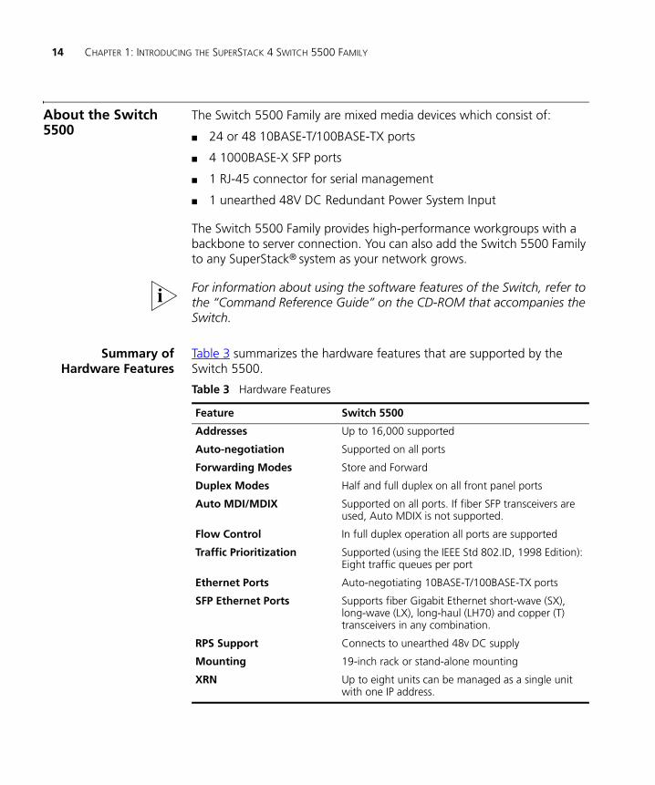
About the Switch 5500
The Switch 5500 Family are mixed media devices which consist of:
■ 24 or 48 10BASE-T/100BASE-TX ports
■ 4 1000BASE-X SFP ports
■ 1 RJ-45 connector for serial management
■ 1 unearthed 48V DC Redundant Power System Input
The Switch 5500 Family provides high-performance workgroups with a backbone to server connection. You can also add the Switch 5500 Family to any SuperStack® system as your network grows.
For information about using the software features of the Switch, refer to the “Command Reference Guide” on the CD-ROM that accompanies the Switch.
Summary ofHardware Features
Table 3 summarizes the hardware features that are supported by the Switch 5500.
Table 3 Hardware Features
Feature Switch 5500
Addresses Up to 16,000 supported
Auto-negotiation Supported on all ports
Forwarding Modes Store and Forward
Duplex Modes Half and full duplex on all front panel ports
Auto MDI/MDIX Supported on all ports. If fiber SFP transceivers are used, Auto MDIX is not supported.
Flow Control In full duplex operation all ports are supported
Traffic Prioritization Supported (using the IEEE Std 802.ID, 1998 Edition): Eight traffic queues per port
Ethernet Ports Auto-negotiating 10BASE-T/100BASE-TX ports
SFP Ethernet Ports Supports fiber Gigabit Ethernet short-wave (SX), long-wave (LX), long-haul (LH70) and copper (T) transceivers in any combination.
RPS Support Connects to unearthed 48v DC supply
Mounting 19-inch rack or stand-alone mounting
XRN Up to eight units can be managed as a single unit with one IP address.
Switch 5500 — Front View Detail 15
DUA1715-0AAA02.book Page 15 Wednesday, March 23, 2005 11:17 AM
Switch 5500 — Front View Detail
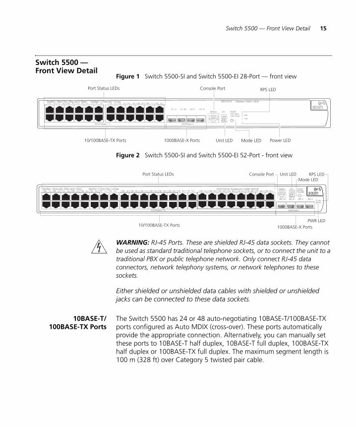
Figure 1 Switch 5500-SI and Switch 5500-EI 28-Port — front view
Figure 2 Switch 5500-SI and Switch 5500-EI 52-Port - front view
WARNING: RJ-45 Ports. These are shielded RJ-45 data sockets. They cannot be used as standard traditional telephone sockets, or to connect the unit to a traditional PBX or public telephone network. Only connect RJ-45 data connectors, network telephony systems, or network telephones to these sockets.
Either shielded or unshielded data cables with shielded or unshielded jacks can be connected to these data sockets.
10BASE-T/100BASE-TX Ports
The Switch 5500 has 24 or 48 auto-negotiating 10BASE-T/100BASE-TX ports configured as Auto MDIX (cross-over). These ports automatically provide the appropriate connection. Alternatively, you can manually set these ports to 10BASE-T half duplex, 10BASE-T full duplex, 100BASE-TX half duplex or 100BASE-TX full duplex. The maximum segment length is 100 m (328 ft) over Category 5 twisted pair cable.
Unit LED
Console Port
Mode LED Power LED10/100BASE-TX Ports
Port Status LEDs
1000BASE-X Ports
RPS LED
Unit LEDConsole PortMode LED
RPS LED
10/100BASE-TX Ports
Port Status LEDs
1000BASE-X PortsPWR LED
16 CHAPTER 1: INTRODUCING THE SUPERSTACK 4 SWITCH 5500 FAMILY
DUA1715-0AAA02.book Page 16 Wednesday, March 23, 2005 11:17 AM
1000BASE-X SFP Ports SFP (Small Form Factor Pluggable) ports support fiber Gigabit Ethernet short-wave (SX), long-wave (LX), long-haul (LH70) and copper (T) SFP Transceivers in any combination. This offers you the flexibility of using SFP transceivers to provide connectivity between the Switch and remote 1000 Mbps workgroups or to create a high capacity aggregated link backbone connection.
The default state for these ports is auto-negotiation enabled, where the speed, duplex and flow control modes are negotiated. As the speed and duplex modes are fixed by the media type, only the flow control is negotiated with the link partner. Alternatively, auto-negotiation can be disabled (except 1000BASE-T which auto-neogtiation is mandatory) and the flow control setting can be manually configured.
Console Port The console port allows you to connect a terminal and perform remote or local out-of-band management. As the console port on the Switch is an RJ-45 port, you will need to connect an RJ-45 to DB9 converter cable to a standard null modem cable in order to connect a terminal.
Unit LED The Unit LED is a seven segment display visible on the front of the Switch. The Unit LED can be used to indicate the unit number in a fabric, POST test ID and software upgrade information. In the unlikely event of a hardware fault occurring, the Unit LED may be used to help diagnose the problem. For information on using the Unit LED for problem solving, see “Solving Problems Indicated by LEDs” on page 62
LEDs Table 4 lists LEDs visible on the front of the Switch, and how to read their status. For information on using the LEDs for problem solving, see “Solving Problems Indicated by LEDs” on page 62.
Table 4 LED Behavior
LED Color Indicates
Unit LED
Green Power On Self Test (POST) is in progress. During POST a the test ID number appears in the Unit LED (seven segment display).
or
Software download is in progress. During software download, a clockwise cycling bar appears in the Unit LED.
Green flashing The Switch has failed POST. The Unit LED flashes the number of the test that has failed.
Green flashing ‘f’ There has been a fan failure.
Switch 5500 — Front View Detail 17
DUA1715-0AAA02.book Page 17 Wednesday, March 23, 2005 11:17 AM
Green flashing ‘t’ The Switch is over temperature and unit temperature is critical.
PWR LED
Green The Switch is powered-up and operating normally.
Green flashing Self Test (POST) or Software Download is in progress.
Yellow flashing One or more ports have failed POST.
Red The Switch has failed its Power On Self Test.
Off The Switch is not receiving power or there is a fault with the Power Supply Unit.
Mode LED
Speed Green 10/100 Port Speed and Activity, Gigabit SFP Status and Activity, or Stack Status and Activity.
Duplex Yellow 10/100 Duplex and Activity, Gigabit SFP Duplex and Activity, or Stack Activity.
RPS LED
Green AC and RPS supply connected.
Yellow AC failed or not connected. RPS supply is OK.
Off There is no RPS supply connected.
10/100BASE-T/TX Port LEDs
Speed Green A high speed (100 Mbps) link is present, blinking off for every packet received or transmitted.
Yellow A low speed (10 Mbps) link is present, blinking off for every packet received or transmitted.
Yellow Flashing The port has failed POST.
Off No link is present.
Duplex Green Full duplex, blinking off for every packet received or transmitted.
Yellow Half duplex, blinking off for every packet received or transmitted.
Yellow flashing The port has failed POST.
Off No link is present.
1000BASE-X Port LEDs
Speed Green A high speed (1000 Mbps) link is present.
Yellow Flashing Port failed POST.
Off No link is present.
Duplex Green Full duplex packets are being transmitted/received on the port.
LED Color Indicates
18 CHAPTER 1: INTRODUCING THE SUPERSTACK 4 SWITCH 5500 FAMILY
DUA1715-0AAA02.book Page 18 Wednesday, March 23, 2005 11:17 AM
Switch 5500 — Rear View Detail
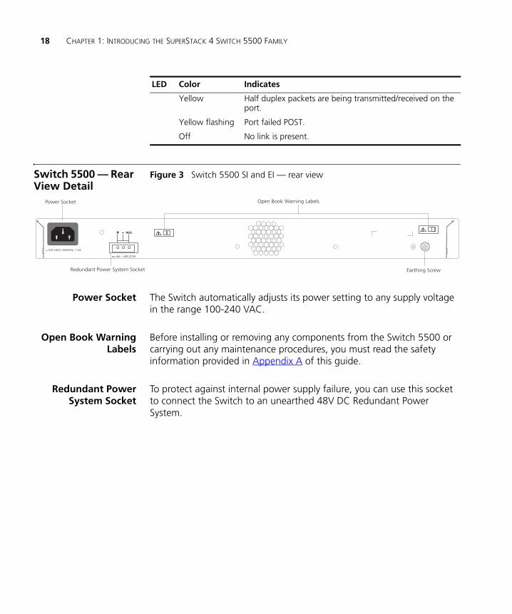
Figure 3 Switch 5500 SI and EI — rear view
Power Socket The Switch automatically adjusts its power setting to any supply voltage in the range 100-240 VAC.
Open Book WarningLabels
Before installing or removing any components from the Switch 5500 or carrying out any maintenance procedures, you must read the safety information provided in Appendix A of this guide.
Redundant PowerSystem Socket
To protect against internal power supply failure, you can use this socket to connect the Switch to an unearthed 48V DC Redundant Power System.
Yellow Half duplex packets are being transmitted/received on the port.
Yellow flashing Port failed POST.
Off No link is present.
LED Color Indicates
Power Socket
Redundant Power System Socket
100-240V; 50/60Hz; 1.0A
Open Book Warning Labels
NULL
Earthing Screw
~-48 -60V;2.0A
Default Settings 19
DUA1715-0AAA02.book Page 19 Wednesday, March 23, 2005 11:17 AM
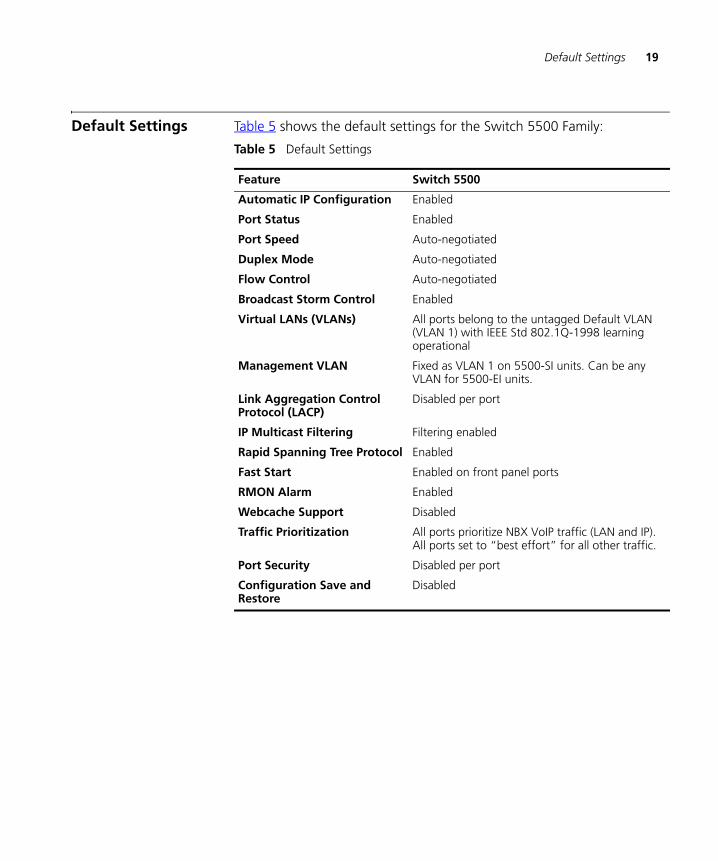
Default Settings Table 5 shows the default settings for the Switch 5500 Family:
Table 5 Default Settings
Feature Switch 5500
Automatic IP Configuration Enabled
Port Status Enabled
Port Speed Auto-negotiated
Duplex Mode Auto-negotiated
Flow Control Auto-negotiated
Broadcast Storm Control Enabled
Virtual LANs (VLANs) All ports belong to the untagged Default VLAN (VLAN 1) with IEEE Std 802.1Q-1998 learning operational
Management VLAN Fixed as VLAN 1 on 5500-SI units. Can be any VLAN for 5500-EI units.
Link Aggregation Control Protocol (LACP)
Disabled per port
IP Multicast Filtering Filtering enabled
Rapid Spanning Tree Protocol Enabled
Fast Start Enabled on front panel ports
RMON Alarm Enabled
Webcache Support Disabled
Traffic Prioritization All ports prioritize NBX VoIP traffic (LAN and IP). All ports set to “best effort” for all other traffic.
Port Security Disabled per port
Configuration Save and Restore
Disabled

20 CHAPTER 1: INTRODUCING THE SUPERSTACK 4 SWITCH 5500 FAMILY
DUA1715-0AAA02.book Page 20 Wednesday, March 23, 2005 11:17 AM
DUA1715-0AAA02.book Page 21 Wednesday, March 23, 2005 11:17 AM
2
INSTALLING THE SWITCHThis chapter contains the information you need to install and set up the Switch 5500. It covers the following topics:
■ Package Contents
■ Choosing a Suitable Site
■ Rack-mounting
■ Connecting a Redundant Power Supply
■ Placing Units On Top of Each Other
■ The Power-up Sequence
■ SFP Operation
■ Choosing the Correct Cables
WARNING: Safety Information. Before installing or removing any components from the Switch 5500 or carrying out any maintenance procedures, you must read the safety information provided in Appendix A of this guide.
AVERTISSEMENT: Consignes de sécurité. Avant d'installer ou d'enlever tout composant du Switch 5500 ou d'entamer une procédure de maintenance, lisez les informations relatives à la sécurité qui se trouvent dans l'Appendice A de ce guide.
VORSICHT: Sicherheitsinformationen. Bevor Sie Komponenten aus dem Switch 5500 entfernen oder dem Switch 5500 hinzufuegen oder Instandhaltungsarbeiten verrichten, lesen Sie die Sicherheitsanweisungen, die in Appendix A (Anhang A) in diesem Handbuch aufgefuehrt sind.
ADVERTENCIA: Información de seguridad. Antes de instalar o extraer cualquier componente del Switch 5500 o de realizar tareas de mantenimiento, debe leer la información de seguridad facilitada en el Apéndice A de esta guía del usuario.
22 CHAPTER 2: INSTALLING THE SWITCH
DUA1715-0AAA02.book Page 22 Wednesday, March 23, 2005 11:17 AM
AVVERTENZA: Informazioni di sicurezza. Prima di installare o rimuovere qualsiasi componente dal Switch 5500 o di eseguire qualsiasi procedura di manutenzione, leggere le informazioni di sicurezza riportate nell'Appendice A della presente guida per l'utente.
OSTRZEŻENIE: Informacje o zabezpieczeniach. Przed instalacją lub usunięciem jakichkolwiek elementów z product lub przeprowadzeniem prac konserwacyjnych należy zapoznać się z informacjami o bezpieczeństwie zawartymi w Załączniku A niniejszego podręcznika.
Package Contents ■ Switch unit
■ CD-ROM (includes documentation related to your Switch)
■ Getting Started Guide (this guide)
■ Release Notes
■ Unit Information Labels
■ Warranty Information
■ RPS Flyer
■ Power Cord
■ Console Cable (RJ-45)
■ RPS Connector (and backshell)
■ RPS Connector Cable Tie
■ Earthing Lead
■ 2 x Mounting brackets
■ 4 x Screws
■ 4 x Rubber feet
Choosing a Suitable Site
The Switch is suited for use on a desktop, either free standing or mounted in a standard 19-inch equipment rack. Alternatively, the Switch can be mounted in a wiring closet or equipment room. A rack-mounting kit containing two mounting brackets is supplied with the Switch.
CAUTION: Ensure that the ventilation holes are not obstructed.
When deciding where to position the Switch, ensure that:■ Cabling is located away from:
Rack-mounting 23
DUA1715-0AAA02.book Page 23 Wednesday, March 23, 2005 11:17 AM
■ sources of electrical noise such as radios, transmitters and broadband amplifiers.
■ power lines and fluorescent lighting fixtures
■ The Switch is accessible and cables can be connected easily.
■ Water or moisture cannot enter the case of the Switch.
■ Air flow is not restricted around the Switch or through the vents in the side of the Switch. 3Com recommends that you provide a minimum of 25mm (1in.) clearance.
■ Air temperature around the Switch does not exceed 40 °C (104 °F).
If the Switch is installed in a 19-inch rack or closed assembly its local air temperature may be greater than room ambient temperature.
■ The air is as free from dust as possible.
■ The unit is installed in a clean, air conditioned environment.
■ No more than eight Switch units are placed on top of one another, if the units are free-standing.
■ The Switch is situated away from sources of conductive (electrical) dust, for example laser printers.
■ The AC supply used by the Switch is separate to that used by units that generate high levels of AC noise, for example air conditioning units and laser printers.
Rack-mounting The Switch 5500 is 1U high and will fit in most standard 19-inch racks.
CAUTION: Disconnect all cables from the Switch before continuing. Remove all self adhesive pads from the underside of the Switch if they have been fitted.
To rack-mount your Switch:
1 Place the Switch the right way up on a hard flat surface, with the front facing towards you.
2 Locate a mounting bracket over the mounting holes on one side of the front of the Switch, as shown in Figure 4.
You can also rack mount your Switch using the mounting holes at the rear of the Switch.
24 CHAPTER 2: INSTALLING THE SWITCH
DUA1715-0AAA02.book Page 24 Wednesday, March 23, 2005 11:17 AM
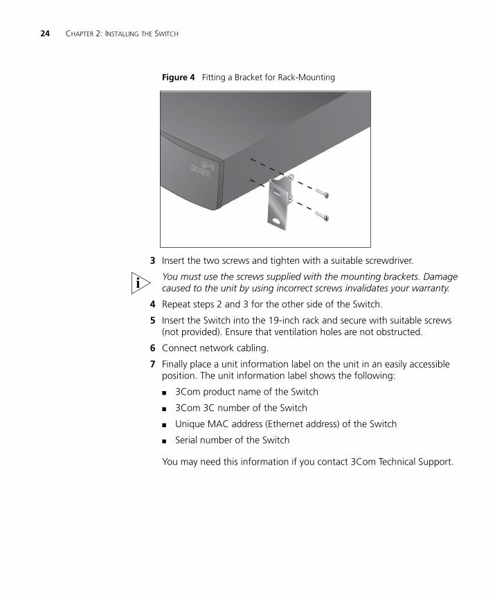
Figure 4 Fitting a Bracket for Rack-Mounting
3 Insert the two screws and tighten with a suitable screwdriver.
You must use the screws supplied with the mounting brackets. Damage caused to the unit by using incorrect screws invalidates your warranty.
4 Repeat steps 2 and 3 for the other side of the Switch.
5 Insert the Switch into the 19-inch rack and secure with suitable screws (not provided). Ensure that ventilation holes are not obstructed.
6 Connect network cabling.
7 Finally place a unit information label on the unit in an easily accessible position. The unit information label shows the following:
■ 3Com product name of the Switch
■ 3Com 3C number of the Switch
■ Unique MAC address (Ethernet address) of the Switch
■ Serial number of the Switch
You may need this information if you contact 3Com Technical Support.
Connecting a Redundant Power Supply 25
DUA1715-0AAA02.book Page 25 Wednesday, March 23, 2005 11:17 AM
Connecting a Redundant Power Supply
The Switch 5500 has an unearthed 48V DC Redundant Power Supply socket.
WARNING: The installation of the Redundant Power Supply (RPS) should only be carried out by properly trained and qualified personnel.
WARNING: These instructions must be read in conjunction with the RPS flyer and the safety and installation instructions supplied with your RPS.
WARNING: When powering any Switch 5500 from an RPS, the unit must be earthed (grounded). This can be achieved by either connecting the power cord to the unit or by connecting the earth terminal on the rear of the unit to a reliable electrical earth, or by connecting both. You must ensure that the earth connection is made before connecting the DC supply from the RPS.
WARNING: Any RPS must be approved as an unearthed SELV output in accordance with IEC 60950-1/UL 60950-1/EN 60950-1.
WARNING: The characteristics of the Switch 5500 DC supply input are given in Appendix C on page 105.
The Switch 5500 can be powered in three different ways:
■ AC Mains only — does not offer any power redundancy. If the AC mains supply or the AC power supply fail, the Switch will power off.
■ AC Mains and Unearthed 48V DC (primary supply) — the internal AC supply acts as the backup in the event of a DC power failure.
■ DC only — the Switch does not need an AC supply and the resiliency is provided by the DC supply. This is useful in an environment where only DC power is available.
The RPS provides two main benefits to the customer:
■ Power Redundancy — if a Switch is powered from the mains supply unit, a failure of the internal power supply will cause the Switch to fail. This can be overcome by connecting both the AC and DC RPS supplies to the Switch. Additional redundancy can also be added to the DC power by using (N+1) DC power supplies to further increase the availability of the system.
■ Uninterruptible Power — the system allows easy connection and maintenance of batteries to the RPS shelf to further increase the availability of the system.
26 CHAPTER 2: INSTALLING THE SWITCH
DUA1715-0AAA02.book Page 26 Wednesday, March 23, 2005 11:17 AM
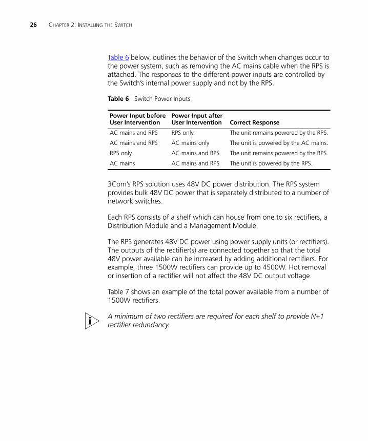
Table 6 below, outlines the behavior of the Switch when changes occur to the power system, such as removing the AC mains cable when the RPS is attached. The responses to the different power inputs are controlled by the Switch’s internal power supply and not by the RPS.
Table 6 Switch Power Inputs
3Com’s RPS solution uses 48V DC power distribution. The RPS system provides bulk 48V DC power that is separately distributed to a number of network switches.
Each RPS consists of a shelf which can house from one to six rectifiers, a Distribution Module and a Management Module.
The RPS generates 48V DC power using power supply units (or rectifiers). The outputs of the rectifier(s) are connected together so that the total 48V power available can be increased by adding additional rectifiers. For example, three 1500W rectifiers can provide up to 4500W. Hot removal or insertion of a rectifier will not affect the 48V DC output voltage.
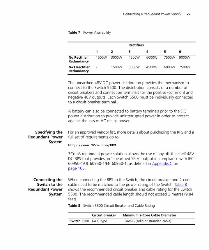
Table 7 shows an example of the total power available from a number of 1500W rectifiers.
A minimum of two rectifiers are required for each shelf to provide N+1 rectifier redundancy.
Power Input before User Intervention
Power Input after User Intervention Correct Response
AC mains and RPS RPS only The unit remains powered by the RPS.
AC mains and RPS AC mains only The unit is powered by the AC mains.
RPS only AC mains and RPS The unit remains powered by the RPS.
AC mains AC mains and RPS The unit is powered by the RPS.
Connecting a Redundant Power Supply 27
DUA1715-0AAA02.book Page 27 Wednesday, March 23, 2005 11:17 AM
Table 7 Power Availability
The unearthed 48V DC power distribution provides the mechanism to connect to the Switch 5500. The distribution consists of a number of circuit breakers and connection terminals for the positive (common) and negative 48V outputs. Each Switch 5500 must be individually connected to a circuit breaker terminal.
A battery can also be connected to battery terminals prior to the DC power distribution to provide uninterrupted power in order to protect against the loss of AC mains power.
Specifying theRedundant Power
System
For an approved vendor list, more details about purchasing the RPS and a full set of requirements go to:
http://www.3Com.com/RPS
3Com’s redundant power solution allows the use of any off-the-shelf 48V DC RPS that provides an ‘unearthed SELV’ output in compliance with IEC 60950-1/UL 60950-1/EN 60950-1, as defined in Appendix C on page 105.
Connecting theSwitch to the
Redundant PowerSystem
When connecting the RPS to the Switch, the circuit breaker and 2-core cable need to be matched to the power rating of the Switch. Table 8 shows the recommended circuit breaker and cable rating for the Switch 5500. The recommended cable length should not exceed 3 metres (9.84 feet).
Table 8 Switch 5500 Circuit Breaker and Cable Rating
Rectifiers
1 2 3 4 5 6
No Rectifier Redundancy
1500W 3000W 4500W 6000W 7500W 9000W
N+1 Rectifier Redundancy
- 1500W 3000W 4500W 6000W 7500W
Circuit Breaker Minimum 2-Core Cable Diameter
Switch 5500 6A C type 18AWG (solid or stranded cable)
28 CHAPTER 2: INSTALLING THE SWITCH
DUA1715-0AAA02.book Page 28 Wednesday, March 23, 2005 11:17 AM
Connecting theEarthing Cable
Use the earthing cable that accompanies your Switch if the length is suitable, alternatively use the earthing cable specification as defined in Appendix C on page 105.
The recommended cable length should not exceed 3 metres (9.84 feet).
WARNING: RPS Manufacturers recommendations must be followed when connecting the cable to the RPS.
WARNING: Ensure that the circuit breaker in the RPS is in the open (off) position when connecting the cable to the RPS.
WARNING: You must ensure that the positive terminal on the Switch is connected to the positive (common) terminal of the RPS and that the negative terminal on the Switch is connected to the negative (circuit breaker) terminal of the RPS.
WARNING: Ensure that the circuit breaker in the RPS is in the open (off) position when connecting the RPS cable and connector to the Switch.
Figure 5 shows how to connect the power supply to the RPS socket in the back of the Switch. Use the cable tie supplied with your Switch to support the cable at the rear of the RPS connector as shown.
Connecting a Redundant Power Supply 29
DUA1715-0AAA02.book Page 29 Wednesday, March 23, 2005 11:17 AM
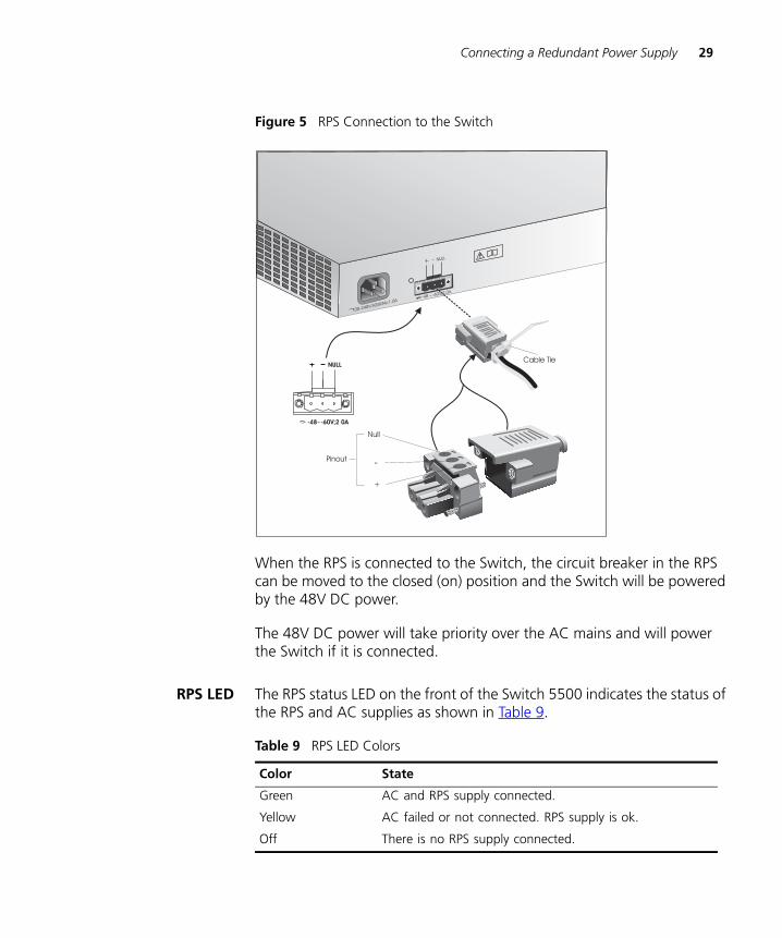
Figure 5 RPS Connection to the Switch
When the RPS is connected to the Switch, the circuit breaker in the RPS can be moved to the closed (on) position and the Switch will be powered by the 48V DC power.
The 48V DC power will take priority over the AC mains and will power the Switch if it is connected.
RPS LED The RPS status LED on the front of the Switch 5500 indicates the status of the RPS and AC supplies as shown in Table 9.
Table 9 RPS LED Colors
+ - NULL
-48 -60V;2.0A
100-240V;50/60Hz;1.0A
~
NULL
-48 -60V;2 0A
Null
+
-Pinout
Cable Tie
Color State
Green AC and RPS supply connected.
Yellow AC failed or not connected. RPS supply is ok.
Off There is no RPS supply connected.
30 CHAPTER 2: INSTALLING THE SWITCH
DUA1715-0AAA02.book Page 30 Wednesday, March 23, 2005 11:17 AM
Placing Units On Top of Each Other
If the Switch units are free-standing, up to eight units can be placed one on top of the other. If you are mixing a variety of SuperStack® units, the smaller units must be positioned at the top.
If you are placing Switch units one on top of the other, you must use the self-adhesive rubber feet supplied. Apply the feet to the underside of each Switch, sticking one in the marked area at each corner. Place the Switch units on top of each other, ensuring that the feet of the upper unit sit fully on the lower unit.
The Power-up Sequence
The following sections describe how to get your Switch 5500 powered-up and ready for operation.
Powering-up theSwitch 5500
Use the following sequence of steps to power-up the Switch.
1 Plug the power cord into the power socket at the rear of the Switch.
2 Plug the other end of the power cord into your power outlet.
The Switch powers-up and runs through its Power On Self Test (POST), which takes approximately one minute.
Checking for CorrectOperation of LEDs
During the Power On Self Test, all ports on the Switch are disabled and the LEDs light. The PWR LED will flash green during the POST.
When the POST has completed, check the PWR LED to make sure that your Switch is operating correctly. Table 10 shows possible colors for the LED.
Table 10 PWR LED Colors
Color State
Green The Switch is powered-up and operating normally.
Red The Switch has failed its Power On Self Test (POST).
Yellow flashing Some ports have failed POST*
* In this event you can still use the Switch via the remaining ports that have passed the POST.
Off The Switch is not receiving power.
SFP Operation 31
DUA1715-0AAA02.book Page 31 Wednesday, March 23, 2005 11:17 AM
If there is evidence of a problem, see “Solving Problems Indicated by LEDs” on page 62 for a list of suggested solutions.
CAUTION: The Switch has no ON/OFF switch; the only method of connecting or disconnecting mains power is by connecting or disconnecting the power cord.
SFP Operation The following section describes how to insert an SFP transceiver into an SFP port.
SFP transceivers are hot-insertable and hot-swappable. You can remove them from and insert them into any SFP port without having to power down the Switch.
You will need to install an SFP transceiver if you wish to create an XRN Distributed Fabric as an SFP port is used to interconnect the Switches.
Approved SFPTransceivers
The following list of approved Gigabit Ethernet SFP transceivers is correct at the time of publication.
■ 3CSFP91 SFP (1000BASE-SX)
■ 3CSFP92 SFP (1000BASE-LX)
■ 3CSFP97 SFP (1000BASE-LH70)
■ 3CSFP93 SFP (1000BASE-T)
To access the latest list of approved SFP transceivers for the Switch on the 3Com Corporation World Wide Web site, enter this URL into your internet browser:
http://www.3com.com
Inserting an SFPTransceiver
To be recognized as valid, the SFP transceiver must have the following characteristics:
■ 1000BASE-SX SFP transceiver
Use this transceiver to connect Gigabit Ethernet SFP ports on the Switch directly to a multi-mode fiber-optic cable.
■ 1000BASE-LX SFP transceiver
32 CHAPTER 2: INSTALLING THE SWITCH
DUA1715-0AAA02.book Page 32 Wednesday, March 23, 2005 11:17 AM
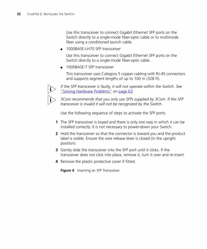
Use this transceiver to connect Gigabit Ethernet SFP ports on the Switch directly to a single-mode fiber-optic cable or to multimode fiber using a conditioned launch cable.
■ 1000BASE-LH70 SFP transceiver
Use this transceiver to connect Gigabit Ethernet SFP ports on the Switch directly to a single-mode fiber-optic cable.
■ 1000BASE-T SFP transceiver
This transceiver uses Category 5 copper cabling with RJ-45 connectors and supports segment lengths of up to 100 m (328 ft).
If the SFP transceiver is faulty, it will not operate within the Switch. See “Solving Hardware Problems” on page 63.
3Com recommends that you only use SFPs supplied by 3Com. If the SFP transceiver is invalid it will not be recognized by the Switch.
Use the following sequence of steps to activate the SFP ports:
1 The SFP transceiver is keyed and there is only one way in which it can be installed correctly. It is not necessary to power-down your Switch.
2 Hold the transceiver so that the connector is toward you and the product label is visible. Ensure the wire release lever is closed (in the upright position).
3 Gently slide the transceiver into the SFP port until it clicks. If the transceiver does not click into place, remove it, turn it over and re-insert.
4 Remove the plastic protective cover if fitted.
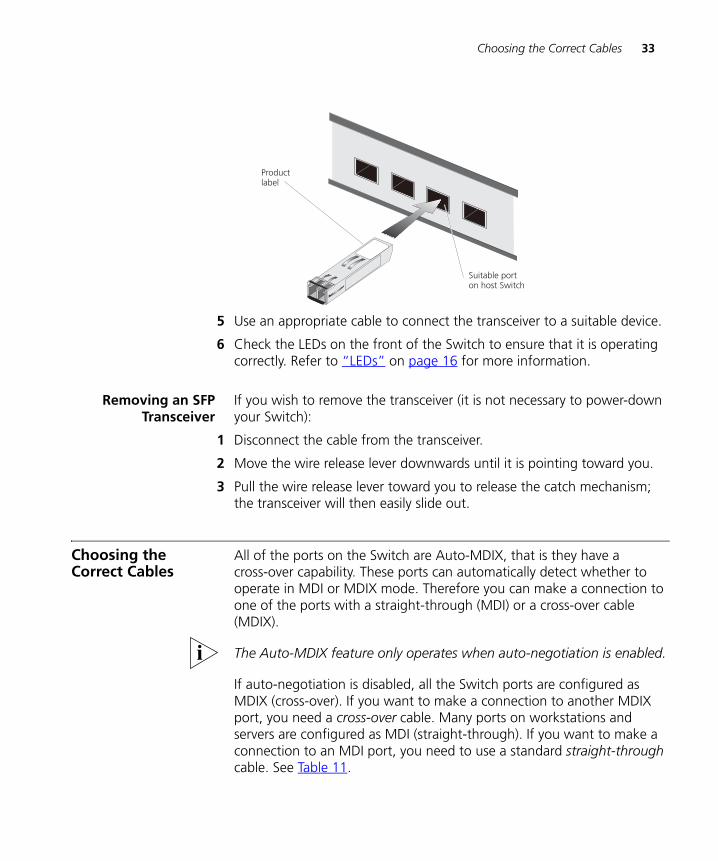
Figure 6 Inserting an SFP Transceiver
Choosing the Correct Cables 33
DUA1715-0AAA02.book Page 33 Wednesday, March 23, 2005 11:17 AM
5 Use an appropriate cable to connect the transceiver to a suitable device.
6 Check the LEDs on the front of the Switch to ensure that it is operating correctly. Refer to “LEDs” on page 16 for more information.
Removing an SFPTransceiver
If you wish to remove the transceiver (it is not necessary to power-down your Switch):
1 Disconnect the cable from the transceiver.
2 Move the wire release lever downwards until it is pointing toward you.
3 Pull the wire release lever toward you to release the catch mechanism; the transceiver will then easily slide out.
Choosing the Correct Cables
All of the ports on the Switch are Auto-MDIX, that is they have a cross-over capability. These ports can automatically detect whether to operate in MDI or MDIX mode. Therefore you can make a connection to one of the ports with a straight-through (MDI) or a cross-over cable (MDIX).
The Auto-MDIX feature only operates when auto-negotiation is enabled.
If auto-negotiation is disabled, all the Switch ports are configured as MDIX (cross-over). If you want to make a connection to another MDIX port, you need a cross-over cable. Many ports on workstations and servers are configured as MDI (straight-through). If you want to make a connection to an MDI port, you need to use a standard straight-through cable. See Table 11.
Productlabel
Suitable porton host Switch
34 CHAPTER 2: INSTALLING THE SWITCH
DUA1715-0AAA02.book Page 34 Wednesday, March 23, 2005 11:17 AM
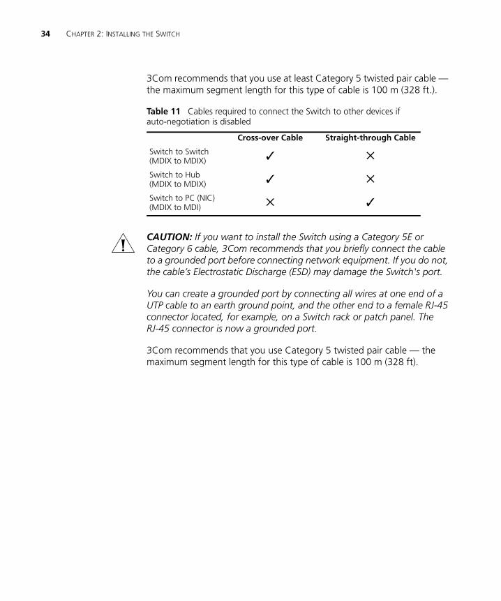
3Com recommends that you use at least Category 5 twisted pair cable — the maximum segment length for this type of cable is 100 m (328 ft.).
Table 11 Cables required to connect the Switch to other devices if auto-negotiation is disabled
CAUTION: If you want to install the Switch using a Category 5E or Category 6 cable, 3Com recommends that you briefly connect the cable to a grounded port before connecting network equipment. If you do not, the cable’s Electrostatic Discharge (ESD) may damage the Switch's port.
You can create a grounded port by connecting all wires at one end of a UTP cable to an earth ground point, and the other end to a female RJ-45 connector located, for example, on a Switch rack or patch panel. The RJ-45 connector is now a grounded port.
3Com recommends that you use Category 5 twisted pair cable — the maximum segment length for this type of cable is 100 m (328 ft).
Cross-over Cable Straight-through Cable
Switch to Switch(MDIX to MDIX) ✓ ✕
Switch to Hub(MDIX to MDIX) ✓ ✕
Switch to PC (NIC)(MDIX to MDI) ✕ ✓
DUA1715-0AAA02.book Page 29 Wednesday, March 23, 2005 11:17 AM
3
SETTING UP FOR MANAGEMENTTo make full use of the features offered by your Switch, and to change and monitor the way it works, you have to access the management software that resides on the Switch. This is known as managing the Switch.
Managing the Switch can help you to improve the efficiency of the Switch and therefore the overall performance of your network.
This chapter explains the initial set up of the Switch and the different methods of accessing the management software to manage a Switch. It covers the following topics:
■ Methods of Managing a Switch
■ Setting Up Overview
■ Manually Configuring IP Information
■ Viewing Automatically Configured IP Information
■ Setting Up Command Line Interface Management
■ Setting Up Command Line Interface Management using SSH
■ Setting Up Web Interface Management
■ Setting Up SNMP Management V1 or V2
■ Default Users and Passwords
■ Configuration Conversion Utility
30 CHAPTER 3: SETTING UP FOR MANAGEMENT
DUA1715-0AAA02.book Page 30 Wednesday, March 23, 2005 11:17 AM
Methods of Managing a Switch
To manage your Switch you can use one of the following methods:
■ Command line interface management
■ Command line interface management using SSH
■ Web interface management
■ SNMP management
Command LineInterface
Management
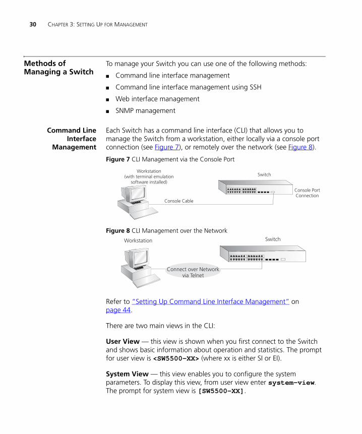
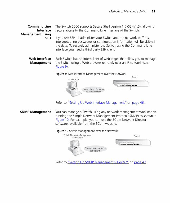
Each Switch has a command line interface (CLI) that allows you to manage the Switch from a workstation, either locally via a console port connection (see Figure 7), or remotely over the network (see Figure 8).
Figure 7 CLI Management via the Console Port
Figure 8 CLI Management over the Network
Refer to “Setting Up Command Line Interface Management” on page 44.
There are two main views in the CLI:
User View — this view is shown when you first connect to the Switch and shows basic information about operation and statistics. The prompt for user view is <SW5500-XX> (where xx is either SI or EI).
System View — this view enables you to configure the system parameters. To display this view, from user view enter system-view. The prompt for system view is [SW5500-XX].
Console PortConnection
Workstation(with terminal emulation
software installed)
Console Cable
Switch
SwitchWorkstation
Connect over Networkvia Telnet
Methods of Managing a Switch 31
DUA1715-0AAA02.book Page 31 Wednesday, March 23, 2005 11:17 AM
Command LineInterface
Management usingSSH
The Switch 5500 supports Secure Shell version 1.5 (SSHv1.5), allowing secure access to the Command Line Interface of the Switch.
If you use SSH to administer your Switch and the network traffic is intercepted, no passwords or configuration information will be visible in the data. To securely administer the Switch using the Command Line Interface you need a third party SSH client.
Web InterfaceManagement
Each Switch has an internal set of web pages that allow you to manage the Switch using a Web browser remotely over an IP network (see Figure 9).
Figure 9 Web Interface Management over the Network
Refer to “Setting Up Web Interface Management” on page 46.
SNMP Management You can manage a Switch using any network management workstation running the Simple Network Management Protocol (SNMP) as shown in Figure 10. For example, you can use the 3Com Network Director software, available from the 3Com website.
Figure 10 SNMP Management over the Network
Refer to “Setting Up SNMP Management V1 or V2” on page 47.
SwitchWorkstation
Connect over Networkvia web browser
SwitchSNMP Network ManagementWorkstation
Connect over Networkusing SNMP
32 CHAPTER 3: SETTING UP FOR MANAGEMENT
DUA1715-0AAA02.book Page 32 Wednesday, March 23, 2005 11:17 AM
Setting Up Overview
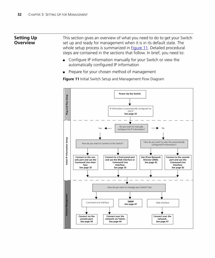
This section gives an overview of what you need to do to get your Switch set up and ready for management when it is in its default state. The whole setup process is summarized in Figure 11. Detailed procedural steps are contained in the sections that follow. In brief, you need to:
■ Configure IP information manually for your Switch or view the automatically configured IP information
■ Prepare for your chosen method of management
Figure 11 Initial Switch Setup and Management Flow Diagram
Plu
g a
nd
Pla
y Se
tup
Init
ial I
P In
form
atio
n S
etu
pFe
atu
re M
anag
emen
t
Power Up the Switch.
IP Information is automatically configured via DHCP
See page 33
Do you want to manually configure the IP information?
Connect to the con-sole port and use the Command Line Inter-
face.See page 35
How do you want to manage your Switch? See
SNMPSee page 47
Command Line Interface
Connect via the console port.See page 44
Web Interface
Connect over the network via Telnet.
See page 44
Connect over the network.
See page 47
How do you want to view the automaticallyconfigured IP information?How do you want to connect to the Switch?
Connect to a front panel port and use the Web Interface or
Command Line Interface.
See page 35
Use 3Com Network Director (3ND).
See page 42
Connect to the console port and use the Command Line
Interface.See page 42
Yes No
Setting Up Overview 33
DUA1715-0AAA02.book Page 33 Wednesday, March 23, 2005 11:17 AM
CAUTION: To protect your Switch from unauthorized access, you must change all three default passwords as soon as possible, even if you do not intend to actively manage your Switch. For more information on default users and changing default passwords, see “Default Users and Passwords” on page 48.
IP Configuration You can use one of the following methods to allocate IP information to your Switch (essential if you wish to manage your Switch across the network).
Manual IP Configuration
When you configure the IP information, the Switch remembers the information that you enter until you change it again.
You should use the Manual IP configuration method if:
■ you do not have a DHCP or BootP server on your network, or
■ you want to remove the risk of the IP address ever changing, or
■ your DHCP or BootP server does not allow you to allocate static IP addresses. (Static IP addresses are necessary to ensure that the Switch is always allocated the same IP information.)
For most installations, 3Com recommends that you configure the Switch IP information manually. This makes management simpler and more reliable as it is not dependent on a DHCP or BootP server, and eliminates the risk of the IP address changing.
To manually enter IP information for your Switch, work through the “Manually Configuring IP Information” section on page 35.
Automatic IP Configuration via DHCP
By default the Switch tries to configure itself with IP Information without requesting user intervention. It tries to obtain an IP address from a DHCP server on the network.
When using automatic IP configuration it is important that the IP address of the Switch is static, otherwise you will not know what the IP address is and it will be difficult to manage. Most DHCP servers allow static IP addresses to be configured so that you know what IP address will be allocated to the Switch. Refer to the documentation that accompanies your DHCP server.
34 CHAPTER 3: SETTING UP FOR MANAGEMENT
DUA1715-0AAA02.book Page 34 Wednesday, March 23, 2005 11:17 AM
For a detailed description of how automatic IP configuration operates, please refer to the Configuration Guide on the CD-ROM that accompanies your Switch or the 3Com Web Site.
You should use the automatic IP configuration method if:
■ your network uses DHCP to allocate IP information, or
■ flexibility is needed. If the Switch is deployed onto a different subnet, it will automatically reconfigure itself with an appropriate IP address, instead of you having to manually reconfigure the Switch.
If the Switch is not allocated with an automatic IP addresss, the IP configuration will be blank or shown as ‘’’’.
If you use the automatic IP configuration method, you need to discover the automatically allocated IP information before you can begin management. Work through the “Viewing Automatically Configured IP Information” section on page 41.
Preparing forManagement
Once your Switch’s initial set up is complete you can set up your chosen management method as described in “Methods of Managing a Switch” on page 30.
For detailed information about the specific web interface operations and command line interface commands and problem solving, refer to the “SuperStack 4 Switch Command Reference Guide” on the CD-ROM that is supplied with the Switch or on the 3Com Web site.
Manually Configuring IP Information 35
DUA1715-0AAA02.book Page 35 Wednesday, March 23, 2005 11:17 AM
Manually Configuring IP Information
You can manually configure the Switch IP information in the following ways:
■ Connecting to the console port — connect a workstation using a console cable to the console port of the Switch. You can then manually enter IP information using the command line interface (CLI).
■ Connecting to a front panel port — connect a workstation using an Ethernet cable to a front panel port of the Switch. You can then manually enter IP information using the web interface or the command line interface (CLI).
Connecting to theConsole Port
To set up your Switch manually you can make a connection to the console port, (this example describes a local connection to the console port, rather than one via a modem). You can do this whilst the Switch is offline, that is, before you connect the Switch to a network, or whilst the Switch is online, that is, connected to a network.
Pre-requisites
■ A workstation with terminal emulation software installed, such as Microsoft Hyperterminal. This software allows you to communicate with the Switch via the console port directly.
■ Documentation supplied with the terminal emulation software.
■ The console cable (RJ-45) supplied with your Switch.
You can find pin-out diagrams for the cable in Appendix B on page 101.
■ You need to have the following so that you can manually set up the Switch with IP information:
■ IP address
■ subnet mask
■ default gateway
■ management VLAN ID, normally set to the default value (1)
36 CHAPTER 3: SETTING UP FOR MANAGEMENT
DUA1715-0AAA02.book Page 36 Wednesday, March 23, 2005 11:17 AM
Connecting the Workstation to the Switch
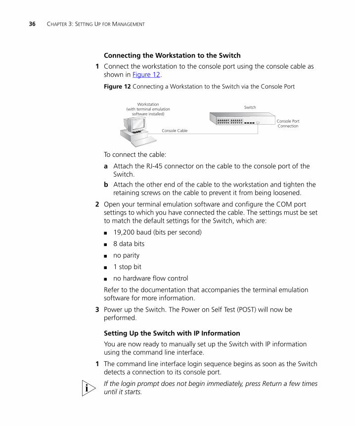
1 Connect the workstation to the console port using the console cable as shown in Figure 12.
Figure 12 Connecting a Workstation to the Switch via the Console Port
To connect the cable:
a Attach the RJ-45 connector on the cable to the console port of the Switch.
b Attach the other end of the cable to the workstation and tighten the retaining screws on the cable to prevent it from being loosened.
2 Open your terminal emulation software and configure the COM port settings to which you have connected the cable. The settings must be set to match the default settings for the Switch, which are:
■ 19,200 baud (bits per second)
■ 8 data bits
■ no parity
■ 1 stop bit
■ no hardware flow control
Refer to the documentation that accompanies the terminal emulation software for more information.
3 Power up the Switch. The Power on Self Test (POST) will now be performed.
Setting Up the Switch with IP Information
You are now ready to manually set up the Switch with IP information using the command line interface.
1 The command line interface login sequence begins as soon as the Switch detects a connection to its console port.
If the login prompt does not begin immediately, press Return a few times until it starts.
Console PortConnection
Workstation(with terminal emulation
software installed)
Console Cable
Switch
Manually Configuring IP Information 37
DUA1715-0AAA02.book Page 37 Wednesday, March 23, 2005 11:17 AM
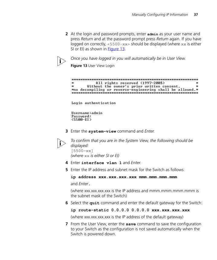
2 At the login and password prompts, enter admin as your user name and press Return and at the password prompt press Return again. If you have logged on correctly, <5500-xx> should be displayed (where xx is either SI or EI) as shown in Figure 13.
Once you have logged in you will automatically be in User View.
Figure 13 User View Login
3 Enter the system-view command and Enter.
To confirm that you are in the System View, the following should be displayed:[5500-xx] (where xx is either SI or EI)
4 Enter interface vlan 1 and Enter.
5 Enter the IP address and subnet mask for the Switch as follows:
ip address xxx.xxx.xxx.xxx mmm.mmm.mmm.mmm
and Enter.
(where xxx.xxx.xxx.xxx is the IP address and mmm.mmm.mmm.mmm is the subnet mask of the Switch)
6 Select the quit command and enter the default gateway for the Switch:
ip route-static 0.0.0.0 0.0.0.0 xxx.xxx.xxx.xxx
(where xxx.xxx.xxx.xxx is the IP address of the default gateway)
7 From the User View, enter the save command to save the configuration to your Switch as the configuration is not saved automatically when the Switch is powered down.
38 CHAPTER 3: SETTING UP FOR MANAGEMENT
DUA1715-0AAA02.book Page 38 Wednesday, March 23, 2005 11:17 AM
The initial set up of your Switch is now complete and the Switch is ready for you to set up your chosen management method. See “Methods of Managing a Switch” on page 30.
If you do not intend to use the command line interface via the console port to manage the Switch, you can disconnect the serial cable and close the terminal emulator software.
Connecting to a FrontPanel Port
To set up your Switch manually you can, alternatively, make a connection to a front panel port. To do this you will need an IP address, refer to “Viewing Automatically Configured IP Information” on page 41 for more information.
The procedure described in this section assumes the unit has been powered up in standalone mode.
Pre-requisites
■ A workstation running a suitable operating system — refer to “Choosing a Browser” on page 46.
■ A Network Interface Card (NIC).
■ A Category 5 twisted pair Ethernet cable with RJ-45 connectors at both ends.
■ A suitable Web browser — refer to “Choosing a Browser”on page 46.
■ Existing IP address of the Switch.
■ You need to have the following so that you can manually set up the Switch with IP information:
■ IP address
■ subnet mask
■ default gateway
■ management VLAN ID, normally set to the default value (1)
Manually Configuring IP Information 39
DUA1715-0AAA02.book Page 39 Wednesday, March 23, 2005 11:17 AM
Connecting the Workstation to the Switch
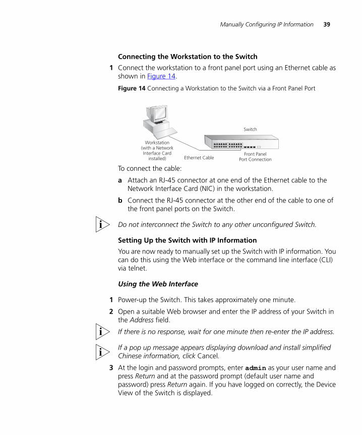
1 Connect the workstation to a front panel port using an Ethernet cable as shown in Figure 14.
Figure 14 Connecting a Workstation to the Switch via a Front Panel Port
To connect the cable:
a Attach an RJ-45 connector at one end of the Ethernet cable to the Network Interface Card (NIC) in the workstation.
b Connect the RJ-45 connector at the other end of the cable to one of the front panel ports on the Switch.
Do not interconnect the Switch to any other unconfigured Switch.
Setting Up the Switch with IP Information
You are now ready to manually set up the Switch with IP information. You can do this using the Web interface or the command line interface (CLI) via telnet.
Using the Web Interface
1 Power-up the Switch. This takes approximately one minute.
2 Open a suitable Web browser and enter the IP address of your Switch in the Address field.
If there is no response, wait for one minute then re-enter the IP address.
If a pop up message appears displaying download and install simplified Chinese information, click Cancel.
3 At the login and password prompts, enter admin as your user name and press Return and at the password prompt (default user name and password) press Return again. If you have logged on correctly, the Device View of the Switch is displayed.
Front PanelPort ConnectionEthernet Cable
Workstation(with a NetworkInterface Card
installed)
Switch
40 CHAPTER 3: SETTING UP FOR MANAGEMENT
DUA1715-0AAA02.book Page 40 Wednesday, March 23, 2005 11:17 AM
4 To enter basic setup information for the Switch, select Administration > IP Setup and then follow the wizard through various system screens to enter the IP address and subnet mask that you want the Switch to use when it is connected to the network. The final page displays a summary of the information entered.
5 Select Save Configuration to save the configuration to your Switch.
The initial set up of your Switch is now complete and the Switch is ready for you to set up your chosen management method. See “Methods of Managing a Switch” on page 30.
Using Command Line Interface via Telnet
1 To start a Telnet session to the unit, click Start in Microsoft Windows 95/98/2000/NT/XP.
a Click Run.
b In the dialogue box that appears type the IP address of the unit, that is: Telnet xxx.xxx.xxx.xxx
(where xxx.xxx.xxx.xxx is the IP address of the Switch)
c Click OK.
2 Press Enter to open a login prompt.
If the login prompt does not begin immediately, press Return a few times until it starts.
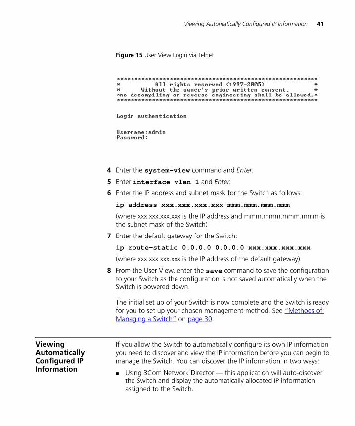
3 At the login and password prompts, enter admin as your user name and press Return at the password prompt. If you have logged on correctly, <5500-xx> is displayed (where xx is either SI or EI) as shown in the example in Figure 15.
Viewing Automatically Configured IP Information 41
DUA1715-0AAA02.book Page 41 Wednesday, March 23, 2005 11:17 AM
Figure 15 User View Login via Telnet
4 Enter the system-view command and Enter.
5 Enter interface vlan 1 and Enter.
6 Enter the IP address and subnet mask for the Switch as follows:
ip address xxx.xxx.xxx.xxx mmm.mmm.mmm.mmm
(where xxx.xxx.xxx.xxx is the IP address and mmm.mmm.mmm.mmm is the subnet mask of the Switch)
7 Enter the default gateway for the Switch:
ip route-static 0.0.0.0 0.0.0.0 xxx.xxx.xxx.xxx
(where xxx.xxx.xxx.xxx is the IP address of the default gateway)
8 From the User View, enter the save command to save the configuration to your Switch as the configuration is not saved automatically when the Switch is powered down.
The initial set up of your Switch is now complete and the Switch is ready for you to set up your chosen management method. See “Methods of Managing a Switch” on page 30.
Viewing Automatically Configured IP Information
If you allow the Switch to automatically configure its own IP information you need to discover and view the IP information before you can begin to manage the Switch. You can discover the IP information in two ways:
■ Using 3Com Network Director — this application will auto-discover the Switch and display the automatically allocated IP information assigned to the Switch.
42 CHAPTER 3: SETTING UP FOR MANAGEMENT
DUA1715-0AAA02.book Page 42 Wednesday, March 23, 2005 11:17 AM
■ Connecting to the Console Port — connect a workstation using a console cable to the console port of the Switch. You can then view the IP information automatically assigned to the Switch using the command line interface (CLI).
Using 3Com NetworkDirector
You can use the 3Com Network Director application (available from the 3Com website) to discover the automatically allocated IP information.
1 Connect your Switch to the network.
2 Power-up the Switch and wait for two minutes.
3 Launch 3Com Network Director and run the Auto-discovery wizard.
3Com Network Director will auto-discover the new Switch and display the IP information that has been automatically allocated to the Switch.
Most DHCP and BootP servers allow static IP addresses to be configured so that you know what IP address the Switch will be given. Refer to the documentation that accompanies your DHCP or BootP server.
If your network does not have a DHCP or BootP server, the workstation running 3Com Network Director must be on the same subnet as the Switch, because Auto-IP addresses are non-routable.
Connecting to theConsole Port
Alternatively, you can view the automatically configured IP information via the command line interface (CLI) through a connection to the console port. (This example describes a local connection to the console port, rather than a remote one via a modem.) For further information on connecting via the console port see “Connecting the Workstation to the Switch”on page 36.
Viewing IP Information via the Console Port
You are now ready to view the automatically allocated IP information using the command line interface.
1 Connect your Switch to the network using the Ethernet cable. As soon as a network connection is made the Switch begins the automatic IP configuration process.
The automatic IP configuration process usually completes within one minute.
2 The command line interface login sequence begins as soon as the Switch detects a connection to its console port.
Viewing Automatically Configured IP Information 43
DUA1715-0AAA02.book Page 43 Wednesday, March 23, 2005 11:17 AM
If the login prompt does not begin immediately, press Return a few times until it starts.
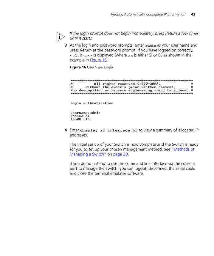
3 At the login and password prompts, enter admin as your user name and press Return at the password prompt. If you have logged on correctly, <5500-xx> is displayed (where xx is either SI or EI) as shown in the example in Figure 16.
Figure 16 User View Login
4 Enter display ip interface br to view a summary of allocated IP addresses.
The initial set up of your Switch is now complete and the Switch is ready for you to set up your chosen management method. See “Methods of Managing a Switch” on page 30.
If you do not intend to use the command line interface via the console port to manage the Switch, you can logout, disconnect the serial cable and close the terminal emulator software.
44 CHAPTER 3: SETTING UP FOR MANAGEMENT
DUA1715-0AAA02.book Page 44 Wednesday, March 23, 2005 11:17 AM
Setting Up Command Line Interface Management
This section describes how you can set up command line interface management using a local console port connection or over the network.
User InterfaceOverview
User interface configuration is provided by the Switch to configure and manage the port data. There are two types of user interfaces:
AUX User Interface — used to log in to your Switch via the console port. A fabric can have up to eight AUX user interfaces.
VTY User Interface — used to Telnet to the Switch. The Switch can have up to five VTY user interfaces.
CLI Management viathe Console Port
To manage a Switch using the command line interface via the local console port connection:
1 Ensure you have connected your workstation to the console port correctly as described in “Connecting to the Console Port” on page 35.
2 Your Switch is now ready to continue being managed and/or configured through the CLI via its console port.
CLI Management overthe Network
To manage a Switch using the command line interface over a network using Telnet:
1 Ensure you have already set up the Switch with IP information as described in “Methods of Managing a Switch” on page 30.
2 Check that you have the IP protocol correctly installed on your management workstation. You can check this by trying to browse the World Wide Web. If you can browse, the IP protocol is installed.
3 Check you can communicate with the Switch by entering a ping command at the DOS prompt in the following format:
c:\ ping xxx.xxx.xxx.xxx(where xxx.xxx.xxx.xxx is the IP address of the Switch)
If you get an error message, check that your IP information has been entered correctly and the Switch is powered up.
4 To open a Telnet session via the DOS prompt, enter the IP address of the Switch that you wish to manage in the following format:
>telnet xxx.xxx.xxx.xxx
Setting Up Command Line Interface Management using SSH 45
DUA1715-0AAA02.book Page 45 Wednesday, March 23, 2005 11:17 AM
(where xxx.xxx.xxx.xxx is the IP address of the Switch)
If opening a Telnet session via third party software you will need to enter the IP address in the format suitable for that software.
5 At the login and password prompts, enter admin as your user name and press Return at the password prompt (or the password of your choice if you have already modified the default passwords).
If the login prompt does not display immediately, press Return a few times until it starts.
6 If you have logged on correctly, the Switch you wish to manage is displayed as <5500-xx> (where xx is either SI or EI, as shown in Figure 13 on page 37).
Setting Up Command Line Interface Management using SSH
This section describes how you can set up Command Line Interface management using SSH over a network.
To manage a Switch using the command line interface over a network using SSH:
1 Ensure you have already set up the Switch with IP information as described in “Methods of Managing a Switch” on page 30.
2 Check that you have the IP protocol correctly installed on your management workstation. You can check this by trying to browse the World Wide Web. If you can browse, the IP protocol is installed.
3 Check you can communicate with the Switch by entering a ping command at the DOS prompt in the following format:
c:\ ping xxx.xxx.xxx.xxx(where xxx.xxx.xxx.xxx is the IP address of the Switch)
If you get an error message, check that your IP information has been entered correctly and the Switch is powered up.
The switch automatically generates a host key pair when it is powered up for the first time, or after any reset to factory defaults. Host key generation may take a while, during which time SSH connections to the switch will be refused.
4 Install an SSH client application on the workstation you want to use to access the switch.
3Com recommends the following SSH clients; PuTTY, OpenSSH and SSH Communications Security Corp Secure Shell.
46 CHAPTER 3: SETTING UP FOR MANAGEMENT
DUA1715-0AAA02.book Page 46 Wednesday, March 23, 2005 11:17 AM
5 Open an SSH session and access the Switch using the Switch’s IP address and port number.
The first time you connect to the switch the client will ask you to confirm that the host key is correct for the device.
6 The Switch and the SSH client will authenticate each other and a secure connection will be established.
7 Enter your usual username and password to access the CLI commands.
For increased security please change the default password when using SSH for the first time.
For further information on generating a host key on your switch and transferring keys to the Switch using TFTP server please refer to the Configuration Guide that is supplied with your Switch.
Setting Up Web Interface Management
This section describes how you can set up web interface management over the network.
Pre-requisites ■ Ensure you have already set up the Switch with IP information as described in “Methods of Managing a Switch” on page 30.
■ Ensure that the Switch is connected to the network using a Category 5 twisted pair Ethernet cable with RJ-45 connectors.
■ A suitable Web browser.
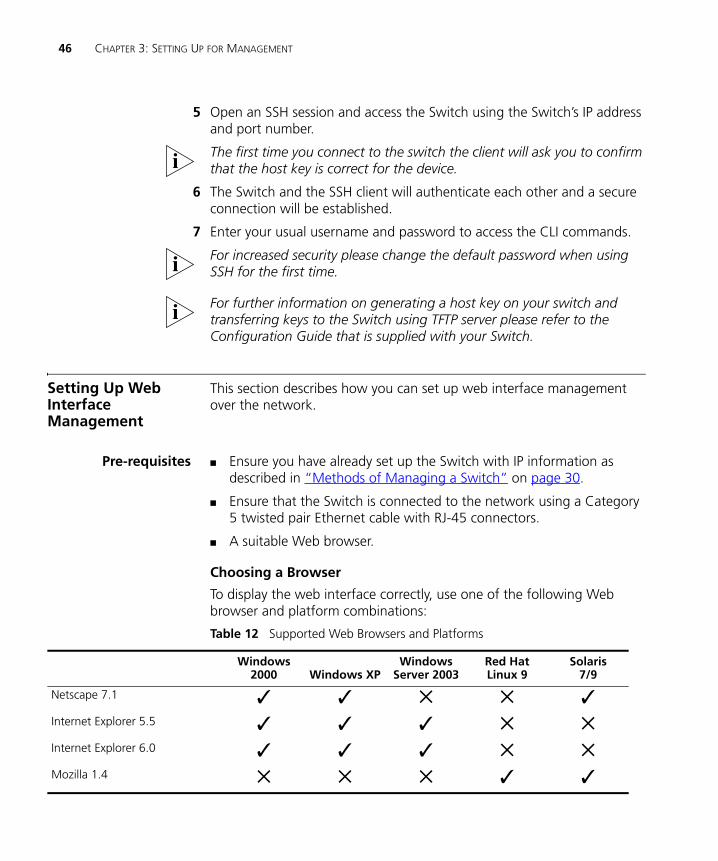
Choosing a Browser
To display the web interface correctly, use one of the following Web browser and platform combinations:
Table 12 Supported Web Browsers and Platforms
Windows 2000 Windows XP
Windows Server 2003
Red Hat Linux 9
Solaris7/9
Netscape 7.1 ✓ ✓ ✕ ✕ ✓Internet Explorer 5.5 ✓ ✓ ✓ ✕ ✕Internet Explorer 6.0 ✓ ✓ ✓ ✕ ✕Mozilla 1.4 ✕ ✕ ✕ ✓ ✓
Setting Up SNMP Management V1 or V2 47
DUA1715-0AAA02.book Page 47 Wednesday, March 23, 2005 11:17 AM
For the browser to operate the web interface correctly, JavaScript™ and Cascading Style Sheets must be enabled on your browser. These features are enabled on a browser by default. You will only need to enable them if you have changed your browser settings.
Web ManagementOver the Network
To manage a Switch using the web interface over an IP network:
1 Check that you have the IP protocol correctly installed on your management workstation. You can check this by trying to browse the World Wide Web. If you can browse, the IP protocol is installed.
2 Check you can communicate with the Switch by entering a ping command at the DOS prompt in the following format:
c:\ ping xxx.xxx.xxx.xxx(where xxx.xxx.xxx.xxx is the IP address of the Switch)
If you get an error message, check that your IP information has been entered correctly and the Switch is powered up.
3 Open your web browser and enter the IP address of the Switch that you wish to manage in the URL locator, for example, in the following format:
http://xxx.xxx.xxx.xxx
4 At the login and password prompts, enter admin as your user name and press Return at the password prompt (or the password of your choice if you have already modified the default passwords).
5 Click on the Device View button to display the web management options.
Setting Up SNMP Management V1 or V2
Any network management application running the Simple Network Management Protocol (SNMP) can manage a Switch if:
■ The correct Management Information Bases (MIBs) are installed on the management workstation.
■ The management workstation is connected to the Switch using a port in VLAN 1 (the Default VLAN). By default, all ports on the Switch are in VLAN 1.
You can use the 3Com Network Director application that is available from the 3Com website to provide SNMP management for your Switch. If you use 3Com Network Director it automatically loads the correct MIBs and necessary files onto your workstation.
48 CHAPTER 3: SETTING UP FOR MANAGEMENT
DUA1715-0AAA02.book Page 48 Wednesday, March 23, 2005 11:17 AM
Pre-requisites ■ Documentation supplied with the SNMP network management application software.
The default read community string is public. To change this setting in System View, enter display snmp community.
The default write community string is private. To change this setting in System View, enter display snmp community.
To manage your Switch using an SNMP network management application, you need to specify SNMP community strings for the users defined on the Switch. You can do this using the command line interface system management snmp community command — refer to the command line interface section of the “SuperStack 4 Switch Command Reference Guide” for more information.
SNMP V3 is on as default. All commands are in snmp menu in System View.
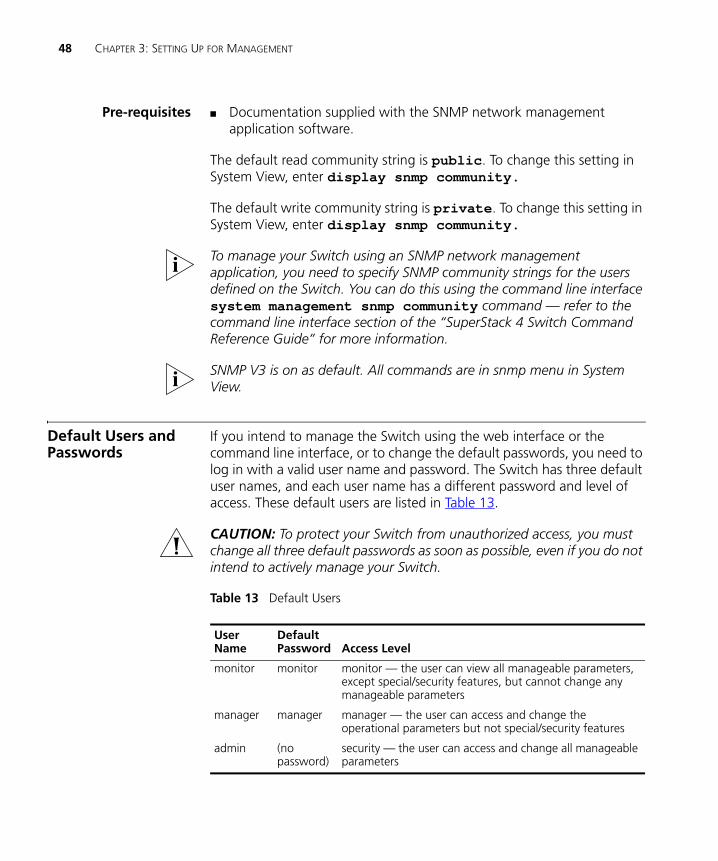
Default Users and Passwords
If you intend to manage the Switch using the web interface or the command line interface, or to change the default passwords, you need to log in with a valid user name and password. The Switch has three default user names, and each user name has a different password and level of access. These default users are listed in Table 13.
CAUTION: To protect your Switch from unauthorized access, you must change all three default passwords as soon as possible, even if you do not intend to actively manage your Switch.
Table 13 Default Users
User Name
DefaultPassword Access Level
monitor monitor monitor — the user can view all manageable parameters, except special/security features, but cannot change any manageable parameters
manager manager manager — the user can access and change the operational parameters but not special/security features
admin (no password)
security — the user can access and change all manageable parameters
Configuration Conversion Utility 49
DUA1715-0AAA02.book Page 49 Wednesday, March 23, 2005 11:17 AM
Use the admin default user name (no password) to login and carry out initial Switch setup.
To set a password for the admin user in the CLI, enter the following from system view:
[5500-xx]local-user admin <cr>[5500-xx-luser-admin]password simple xxxxxxxx
(where xxxxxxxx is your chosen password).
Save the configuration in the User View.
For information on the lost password procedure please refer to the Configuration Guide that is supplied with your Switch.
Configuration Conversion Utility
The 3Com Switch 5500 Configuration Conversion Utility (CCU) enables you to convert the key configuration parameters from a range of 3Com SuperStack II and SuperStack 3 devices to the configuration file format used by your Switch 5500 unit. The utility provides conversion for a number of Switch features
To download the CCU package, select the CCU link on the CD that accompanies your Switch 5500. Alternatively, the CCU download and further information is available at:
http://www.3com.com/switchmigration/

50 CHAPTER 3: SETTING UP FOR MANAGEMENT
DUA1715-0AAA02.book Page 50 Wednesday, March 23, 2005 11:17 AM
DUA1715-0AAA02.book Page 57 Wednesday, March 23, 2005 11:17 AM
4
CREATING AN XRN STACKING FABRICThis chapter contains the information you need to create an XRN Stacking Fabric. It covers the following topics:
■ How To Interconnect Units
■ Guidelines For Interconnecting Units
■ Unit Numbering within the Fabric
The procedure for creating a Fabric with the Switch 5500-SI units is the same procedure as that for creating a Fabric with the Switch 5500-EI units.
How To Interconnect Units
Up to eight 3Com Switch 5500 units can be interconnected to create an XRN Stacking Fabric and then treated as a single manageable unit with one IP address.
You can interconnect your Switches to create an XRN Fabric using a standard 1000 Mbps Ethernet connection. Table 14 lists the different variants of the Switch 5500 family, how they physically interconnect and the level of XRN support offered by the Fabric.
It is not possible to create a Fabric by interconnecting a 3Com Switch 5500 with any other 3Com device or mix Enhanced Image (EI) Switch 5500 units with Standard Image (SI) units.
This section assumes you have either set up your units for management as detailed in Chapter 3 “Setting Up for Management”or that you are using a console cable connected to the console port to set up and allocate IP addresses and so on.
3Com recommends that you do not physically connect the cables on your Fabric ports until you have carried out the initial configuration of the Fabric ports as detailed below.
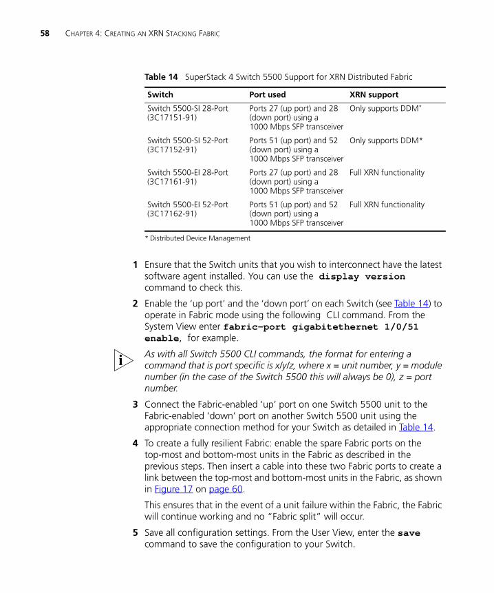
58 CHAPTER 4: CREATING AN XRN STACKING FABRIC
DUA1715-0AAA02.book Page 58 Wednesday, March 23, 2005 11:17 AM
Table 14 SuperStack 4 Switch 5500 Support for XRN Distributed Fabric
1 Ensure that the Switch units that you wish to interconnect have the latest software agent installed. You can use the display version command to check this.
2 Enable the ‘up port’ and the ‘down port’ on each Switch (see Table 14) to operate in Fabric mode using the following CLI command. From the System View enter fabric-port gigabitethernet 1/0/51 enable, for example.
As with all Switch 5500 CLI commands, the format for entering a command that is port specific is x/y/z, where x = unit number, y = module number (in the case of the Switch 5500 this will always be 0), z = port number.
3 Connect the Fabric-enabled ‘up’ port on one Switch 5500 unit to the Fabric-enabled ‘down’ port on another Switch 5500 unit using the appropriate connection method for your Switch as detailed in Table 14.
4 To create a fully resilient Fabric: enable the spare Fabric ports on the top-most and bottom-most units in the Fabric as described in the previous steps. Then insert a cable into these two Fabric ports to create a link between the top-most and bottom-most units in the Fabric, as shown in Figure 17 on page 60.
This ensures that in the event of a unit failure within the Fabric, the Fabric will continue working and no “Fabric split” will occur.
5 Save all configuration settings. From the User View, enter the save command to save the configuration to your Switch.
Switch Port used XRN support
Switch 5500-SI 28-Port (3C17151-91)
Ports 27 (up port) and 28 (down port) using a 1000 Mbps SFP transceiver
Only supports DDM*
* Distributed Device Management
Switch 5500-SI 52-Port (3C17152-91)
Ports 51 (up port) and 52 (down port) using a 1000 Mbps SFP transceiver
Only supports DDM*
Switch 5500-EI 28-Port (3C17161-91)
Ports 27 (up port) and 28 (down port) using a 1000 Mbps SFP transceiver
Full XRN functionality
Switch 5500-EI 52-Port (3C17162-91)
Ports 51 (up port) and 52 (down port) using a 1000 Mbps SFP transceiver
Full XRN functionality
Guidelines For Interconnecting Units 59
DUA1715-0AAA02.book Page 59 Wednesday, March 23, 2005 11:17 AM
Guidelines For Interconnecting Units
This section offers some guidelines for creating a Fabric. Using these guidelines will help prevent problems arising when setting up your Fabric.
■ The maximum number of Switch units that can be interconnected is eight.
■ It is not possible to create a fabric by interconnecting a 3Com Switch 5500 with any other 3Com device (such as 5500G Switch units) or mix Enhanced Image (EI) Switch 5500 units with Standard Image (SI) units.
■ 3Com strongly recommends that you upgrade all Switches to be interconnected to the latest software agent.
■ 3Com recommends that you remove the configuration file from a Switch unit that has previously been used elsewhere in your network before you interconnect to an existing unit. If you do not do this, problems may be caused by conflicting Switch configurations. Use the dir command from the User View to display the configuration files stored on the Switch and locate the [filename].cfg file. Do NOT under any circumstances remove the 3comoscfg.def file (this is the default configuration file).
■ When a port is operating in XRN Fabric mode it will no longer be configurable in the normal way, that is, you cannot control port features such as auto-negotiation, VLANs, static addresses, STP, Aggregated Links, Resilient Links, and so on. However, it is possible to specify the Fabric VLAN.
For a detailed description of how XRN Technology operates and implementation guidelines, please refer to the Configuration Guide on the CD-ROM that accompanies your Switch.
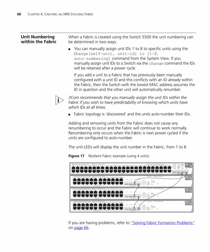
60 CHAPTER 4: CREATING AN XRN STACKING FABRIC
DUA1715-0AAA02.book Page 60 Wednesday, March 23, 2005 11:17 AM
Unit Numbering within the Fabric
When a Fabric is created using the Switch 5500 the unit numbering can be determined in two ways.
■ You can manually assign unit IDs 1 to 8 to specific units using the change[self-unit, unit-id] to [1-8, auto-numbering] command from the System View. If you manually assign unit IDs to a Switch via the change command the IDs will be retained after a power cycle.
If you add a unit to a Fabric that has previously been manually configured with a unit ID and this conflicts with an ID already within the Fabric, then the Switch with the lowest MAC address assumes the ID in question and the other unit will automatically renumber.
3Com recommends that you manually assign the unit IDs within the Fabric if you wish to have predictability of knowing which units have which IDs at all times.
■ Fabric topology is ‘discovered’ and the units auto-number their IDs.
Adding and removing units from the Fabric does not cause any renumbering to occur and the Fabric will continue to work normally. Renumbering only occurs when the Fabric is next power cycled if the units are configured to auto-number.
The unit LEDs will display the unit number in the Fabric, from 1 to 8.
Figure 17 Resilient Fabric example (using 4 units)
If you are having problems, refer to “Solving Fabric Formation Problems” on page 66.
DUA1715-0AAA02.book Page 61 Wednesday, March 23, 2005 11:17 AM
5
PROBLEM SOLVINGThis chapter helps you to diagnose and solve problems you may have with the operation of your Switch. There is also an explanation of IP addressing and upgrading software.
The topics covered are:
■ Solving Problems Indicated by LEDs
■ Solving Hardware Problems
■ Solving Communication Problems
■ Solving Fabric Formation Problems
If you experience a problem that is not listed here, it may be included in the Support section of the SuperStack 4 Switch 5500 Command Reference Guide on the CD-ROM that accompanies your Switch.
For Technical Support information, see Appendix D.
62 CHAPTER 5: PROBLEM SOLVING
DUA1715-0AAA02.book Page 62 Wednesday, March 23, 2005 11:17 AM
Solving Problems Indicated by LEDs
If the LEDs on the Switch indicate a problem, refer to the list of suggested solutions below.
The PWR LED does not light
Check that the power cable is firmly connected to the Switch and to the supply outlet. If the connection is secure and there is still no power, you may have a faulty power cord or an internal fault. Firstly, check the power cord by:
■ testing it in another device.
■ connecting a working power cord to the ‘problem’ device then contact your supplier for advice.
On powering-up, the PWR LED lights Red
The Switch unit has failed its Power On Self Test (POST) because of an internal problem. The fault type will be indicated on the unit LEDs. Contact your supplier for advice.
On powering-up, the PWR LED is flashing yellow
A port has failed and has been automatically disabled. You can verify this by checking that the Port LED is quickly flashing Yellow. If a port fails, the Switch passes its Power On Self Test and continues to operate normally.
A Port LED is flashing yellow
The port has failed and has been automatically disabled. The Switch passes its Power On Self Test and continues to operate normally, even if one or more ports are disabled.
A link is connected and yet the Port LED does not light
Check that:
■ The Switch and the device at the other end of the link (or cable) are connected securely.
■ The devices at both ends of the link are powered-up
■ The quality of cable is satisfactory
■ Auto-negotiation settings are the same at both ends.
Solving Hardware Problems 63
DUA1715-0AAA02.book Page 63 Wednesday, March 23, 2005 11:17 AM
Auto-negotiation problems will occur with 10BASE-T or 100BASE-T where auto-negotiation is disabled and incorrect cables are being used (cross-over or straight)
Auto-negotiation problems will occur with fiber if:
■ The Receiver (RX) and Transceiver (TX) cable connectors are swapped
■ Fibers are broken
■ Auto-negotiation differs at either end (a link appears at the ‘fixed’ end and not at the auto-negotiation end)
Solving Hardware Problems
In the rare event of your Switch unit experiencing a hardware failure, refer to the list of suggested solutions below.
A fan failure warning message is received
Your Switch has a fan monitoring system that will generate fan failure warning messages. Fan failure could potentially reduce the lifetime of the Switch. The monitoring system polls the fan status at periodic intervals while the unit is powered up.
If one fan has failed in the Switch, a warning message will be generated in the following ways:
■ Unit LED — the seven segment display will show a green flashing ‘f’.
■ RMON Trap — if configured, an RMON trap is generated and sent to the management workstation.
■ Command Line Interface — an indication of a general hardware failure is provided through the Top level menu displayed when logging on to the CLI. For more detailed information about the failure select the display logbuffer command.
■ Web interface — an indication of fan failure is provided through the Device Summary table for the specific unit. In addition all Summary tables turn red to indicate the fan failure.
If a fan failure warning message is generated:
1 Power off the unit.
2 Check that the air vents are not obstructed.
64 CHAPTER 5: PROBLEM SOLVING
DUA1715-0AAA02.book Page 64 Wednesday, March 23, 2005 11:17 AM
3 Power cycle the unit. To do this, remove and reconnect the AC mains supply. If the unit has no AC main supply, remove and reconnect the DC RPS supply.
4 If another fan failure warning message is generated via the Command Line Interface or the Web interface, return the unit to 3Com.
Unit fails, no SNMP fan failure message is received
1 Power cycle the unit. To do this, remove and reconnect the AC mains supply. If the unit has no AC mains supply, remove and reconnect the DC RPS supply.
2 Check the command line interface (display logbuffer command) to determine whether a thermal shutdown has occurred.
3 If no, return the unit:
If yes, check that:
■ The air vents are not obstructed.
■ The ambient temperatures and environmental conditions meet those specified in Appendix C.
4 Power cycle the unit. If a further thermal shutdown occurs, and all environmental conditions are satisfactory, return the unit to 3Com.
Error message indicating that the SFP transceiver is invalid
The Switch has identified that the SFP does not meet the minimum requirements for the Switch and has disabled the port. To correct this problem, completely remove the SFP and replace it with a 3Com approved SFP. See “Approved SFP Transceivers” on page 31.
Error message indicating that the SFP transceiver is faulty
To correct this problem, completely remove the SFP and then reinsert it. Alternatively, insert another identical SFP. If the problem persists, contact 3Com Technical Support.
Solving Communication Problems
If you experience communication problems with the Switch, ensure that:
■ The Switch IP address and Management VLAN ID has been configured.
Solving Communication Problems 65
DUA1715-0AAA02.book Page 65 Wednesday, March 23, 2005 11:17 AM
■ If the Switch is separated from your management application by a router, ensure that the default gateway IP address within the Switch is the same as the IP address of the router.
■ The Switch’s IP address has been entered correctly in your network management application (such as 3Com Network Director).
The following is a brief overview of IP addressing, and how to obtain a registered IP address.
IP Addressing
To be managed correctly, each device on your network (for example a Switch or Hub) must have a unique IP address. IP addresses have the format n.n.n.n where n is a decimal number between 0 and 255. An example IP address is 192.168.100.8.
The IP address is split into two parts:
■ The first part (‘192.168.100’ in the example) identifies the network on which the device resides
■ The second part (‘.8’ in the example) identifies the device within the network
The natural subnet mask for this example is 255.255.255.0.
If your network has a connection to the external IP network, that is, you access the Internet, you must apply for a registered IP address.
How do you obtain a registered IP Address?
The IP registration system ensures that every IP address used is unique; if you do not have a registered IP address, you may be using an identical address to someone else and your network will not operate correctly.
InterNIC Registration Services is the organization responsible for supplying registered IP addresses. The following contact information is correct at time of publication:
World Wide Web site: http://www.internic.net
If your IP network is internal to your organization only, that is, you do not access the Internet, you may use any arbitrary IP address as long as it is not being used by another device on your network. 3Com suggests you
66 CHAPTER 5: PROBLEM SOLVING
DUA1715-0AAA02.book Page 66 Wednesday, March 23, 2005 11:17 AM
use addresses in the range 192.168.0.0 to 192.168.255.255 with a subnet mask of 255.255.255.0.
These suggested IP addresses are part of a group of IP addresses that have been set aside specially for use ‘in house’ only.
Solving Fabric Formation Problems
If you are having problems with correctly forming a fabric, first ensure that Spanning Tree is enabled. If it is enabled, do the following:
1 Power off all units in the fabric.
2 Check all the cable connections in the fabric.
3 Check the ports have been enabled as fabric ports.
4 Power on all units in the fabric.
DUA1715-0AAA02.book Page 67 Wednesday, March 23, 2005 11:17 AM
6
UPGRADING SOFTWAREThis chapter describes how to upgrade software to your Switch 5500. It covers the following topics:
■ Upgrading from the Command Line Interface
■ Upgrading from the Bootrom Interface
■ Bootrom Upgrade
68 CHAPTER 6: UPGRADING SOFTWARE
DUA1715-0AAA02.book Page 68 Wednesday, March 23, 2005 11:17 AM
Upgrading from the Command Line Interface
This section describes how to upgrade files to your Switch from the Command Line Interface (CLI).
Introduction Before upgrading the software to your Switch from the CLI, it is important to check the contents of the flash to ensure that there is enough space to download the new files.
The flash space needed for the new files is approximately 5.5 MB.
1 To check the contents of the flash, logon to your Switch either via a telnet connection or directly via the console to display the User View in the CLI and enter the following:
dir unit1>flash:
A file list similar to the following is displayed:
Directory of unit1>flash:/
15367 KB total (10215 KB free)
2 You can check the contents of the flash for the remaining units in the fabric by entering:
dir unit2>flash:dir unit3>flash:dir unit4>flash:dir unit5>flash:dir unit6>flash:dir unit7>flash:
The file list should contain one of each file type (.zip, .def, .cfg and .app).
3 Any additional files should be considered for deletion to allow maximum space for downloading the new files. To delete a file from the list enter:
delete/unreserved unit1>flash:/filename
0 -rw- 714784 Apr 02 2005 01:36:16 s4h03_01_00.zip
1 -rw- 11043 Apr 02 2005 01:37:17 3ComOScfg.def
2 -rw- 11427 Apr 02 2005 00:01:01 3ComOScfg.cfg
3 -rw- 4529259 Apr 02 2005 01:39:57 s4b03_01_00s168.app
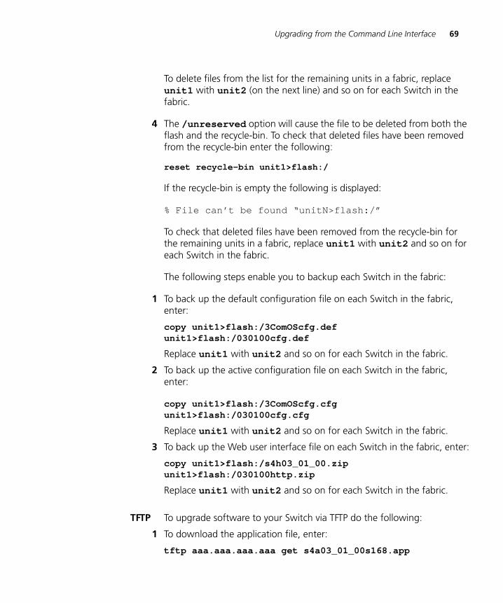
Upgrading from the Command Line Interface 69
DUA1715-0AAA02.book Page 69 Wednesday, March 23, 2005 11:17 AM
To delete files from the list for the remaining units in a fabric, replace unit1 with unit2 (on the next line) and so on for each Switch in the fabric.
4 The /unreserved option will cause the file to be deleted from both the flash and the recycle-bin. To check that deleted files have been removed from the recycle-bin enter the following:
reset recycle-bin unit1>flash:/
If the recycle-bin is empty the following is displayed:
% File can’t be found “unitN>flash:/”
To check that deleted files have been removed from the recycle-bin for the remaining units in a fabric, replace unit1 with unit2 and so on for each Switch in the fabric.
The following steps enable you to backup each Switch in the fabric:
1 To back up the default configuration file on each Switch in the fabric, enter:
copy unit1>flash:/3ComOScfg.def unit1>flash:/030100cfg.def
Replace unit1 with unit2 and so on for each Switch in the fabric.
2 To back up the active configuration file on each Switch in the fabric, enter:
copy unit1>flash:/3ComOScfg.cfg unit1>flash:/030100cfg.cfg
Replace unit1 with unit2 and so on for each Switch in the fabric.
3 To back up the Web user interface file on each Switch in the fabric, enter:
copy unit1>flash:/s4h03_01_00.zip unit1>flash:/030100http.zip
Replace unit1 with unit2 and so on for each Switch in the fabric.
TFTP To upgrade software to your Switch via TFTP do the following:
1 To download the application file, enter:
tftp aaa.aaa.aaa.aaa get s4a03_01_00s168.app
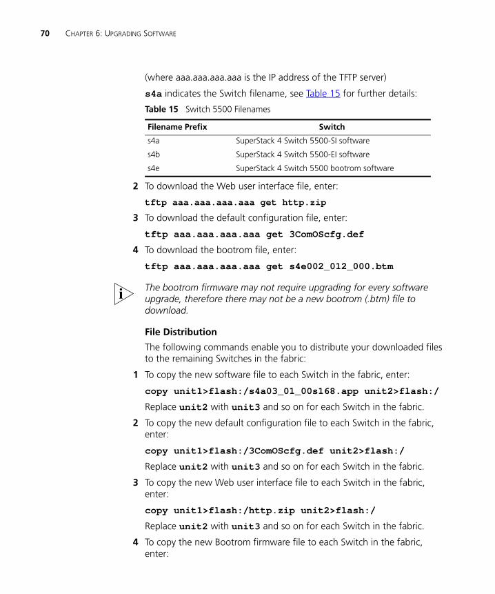
70 CHAPTER 6: UPGRADING SOFTWARE
DUA1715-0AAA02.book Page 70 Wednesday, March 23, 2005 11:17 AM
(where aaa.aaa.aaa.aaa is the IP address of the TFTP server)
s4a indicates the Switch filename, see Table 15 for further details:
Table 15 Switch 5500 Filenames
2 To download the Web user interface file, enter:
tftp aaa.aaa.aaa.aaa get http.zip
3 To download the default configuration file, enter:
tftp aaa.aaa.aaa.aaa get 3ComOScfg.def
4 To download the bootrom file, enter:
tftp aaa.aaa.aaa.aaa get s4e002_012_000.btm
The bootrom firmware may not require upgrading for every software upgrade, therefore there may not be a new bootrom (.btm) file to download.
File Distribution
The following commands enable you to distribute your downloaded files to the remaining Switches in the fabric:
1 To copy the new software file to each Switch in the fabric, enter:
copy unit1>flash:/s4a03_01_00s168.app unit2>flash:/
Replace unit2 with unit3 and so on for each Switch in the fabric.
2 To copy the new default configuration file to each Switch in the fabric, enter:
copy unit1>flash:/3ComOScfg.def unit2>flash:/
Replace unit2 with unit3 and so on for each Switch in the fabric.
3 To copy the new Web user interface file to each Switch in the fabric, enter:
copy unit1>flash:/http.zip unit2>flash:/
Replace unit2 with unit3 and so on for each Switch in the fabric.
4 To copy the new Bootrom firmware file to each Switch in the fabric, enter:
Filename Prefix Switch
s4a SuperStack 4 Switch 5500-SI software
s4b SuperStack 4 Switch 5500-EI software
s4e SuperStack 4 Switch 5500 bootrom software
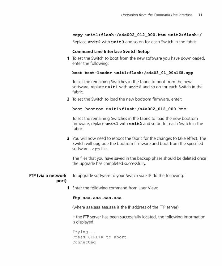
Upgrading from the Command Line Interface 71
DUA1715-0AAA02.book Page 71 Wednesday, March 23, 2005 11:17 AM
copy unit1>flash:/s4e002_012_000.btm unit2>flash:/
Replace unit2 with unit3 and so on for each Switch in the fabric.
Command Line Interface Switch Setup
1 To set the Switch to boot from the new software you have downloaded, enter the following:
boot boot-loader unit1>flash:/s4a03_01_00s168.app
To set the remaining Switches in the fabric to boot from the new software, replace unit1 with unit2 and so on for each Switch in the fabric.
2 To set the Switch to load the new bootrom firmware, enter:
boot bootrom unit1>flash:/s4e002_012_000.btm
To set the remaining Switches in the fabric to load the new bootrom firmware, replace unit1 with unit2 and so on for each Switch in the fabric.
3 You will now need to reboot the fabric for the changes to take effect. The Switch will upgrade the bootrom firmware and boot from the specified software .app file.
The files that you have saved in the backup phase should be deleted once the upgrade has completed successfully.
FTP (via a networkport)
To upgrade software to your Switch via FTP do the following:
1 Enter the following command from User View:
ftp aaa.aaa.aaa.aaa
(where aaa.aaa.aaa.aaa is the IP address of the FTP server)
If the FTP server has been successfully located, the following information is displayed:
Trying...Press CTRL+K to abortConnected
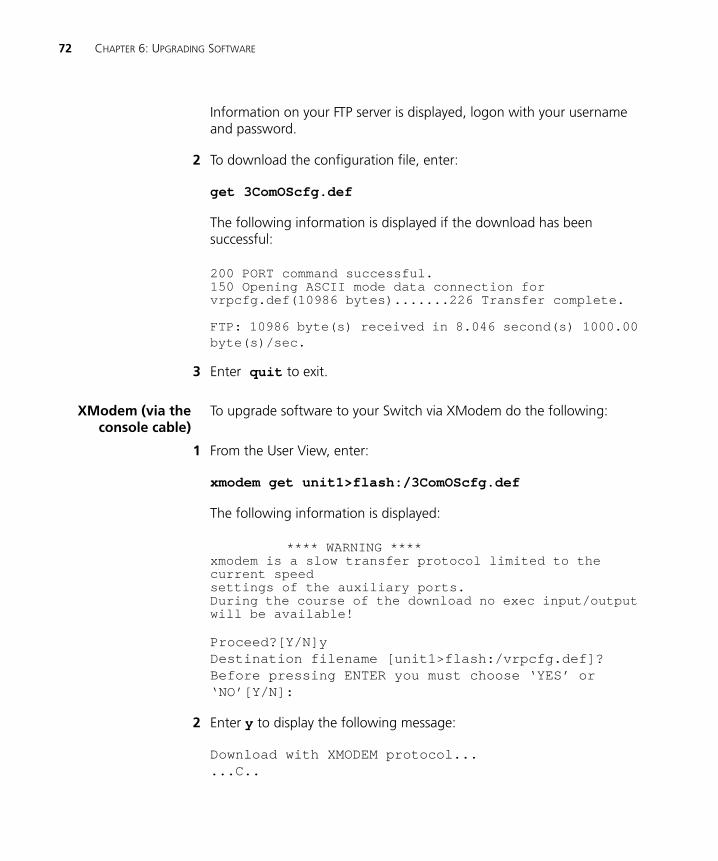
72 CHAPTER 6: UPGRADING SOFTWARE
DUA1715-0AAA02.book Page 72 Wednesday, March 23, 2005 11:17 AM
Information on your FTP server is displayed, logon with your username and password.
2 To download the configuration file, enter:
get 3ComOScfg.def
The following information is displayed if the download has been successful:
200 PORT command successful.150 Opening ASCII mode data connection for vrpcfg.def(10986 bytes).......226 Transfer complete.
FTP: 10986 byte(s) received in 8.046 second(s) 1000.00 byte(s)/sec.
3 Enter quit to exit.
XModem (via theconsole cable)
To upgrade software to your Switch via XModem do the following:
1 From the User View, enter:
xmodem get unit1>flash:/3ComOScfg.def
The following information is displayed:
**** WARNING ****xmodem is a slow transfer protocol limited to the current speedsettings of the auxiliary ports.During the course of the download no exec input/output will be available!
Proceed?[Y/N]yDestination filename [unit1>flash:/vrpcfg.def]?Before pressing ENTER you must choose ‘YES’ or ‘NO’[Y/N]:
2 Enter y to display the following message:
Download with XMODEM protocol......C..
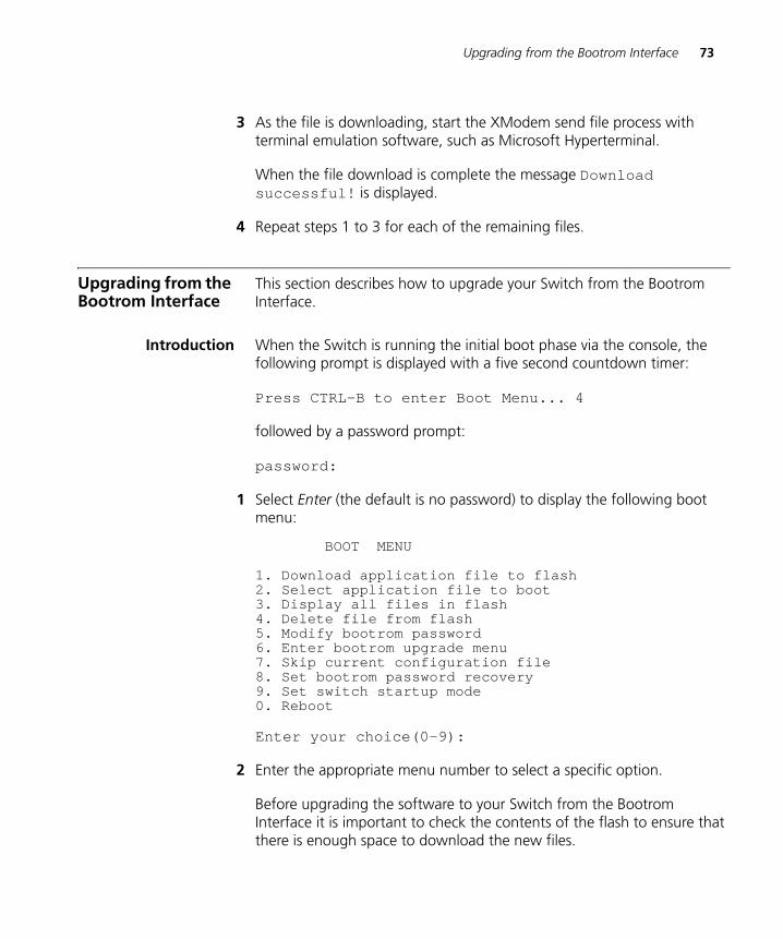
Upgrading from the Bootrom Interface 73
DUA1715-0AAA02.book Page 73 Wednesday, March 23, 2005 11:17 AM
3 As the file is downloading, start the XModem send file process with terminal emulation software, such as Microsoft Hyperterminal.
When the file download is complete the message Download successful! is displayed.
4 Repeat steps 1 to 3 for each of the remaining files.
Upgrading from the Bootrom Interface
This section describes how to upgrade your Switch from the Bootrom Interface.
Introduction When the Switch is running the initial boot phase via the console, the following prompt is displayed with a five second countdown timer:
Press CTRL-B to enter Boot Menu... 4
followed by a password prompt:
password:
1 Select Enter (the default is no password) to display the following boot menu:
BOOT MENU
1. Download application file to flash2. Select application file to boot3. Display all files in flash4. Delete file from flash5. Modify bootrom password6. Enter bootrom upgrade menu7. Skip current configuration file8. Set bootrom password recovery9. Set switch startup mode0. Reboot
Enter your choice(0-9):
2 Enter the appropriate menu number to select a specific option.
Before upgrading the software to your Switch from the Bootrom Interface it is important to check the contents of the flash to ensure that there is enough space to download the new files.
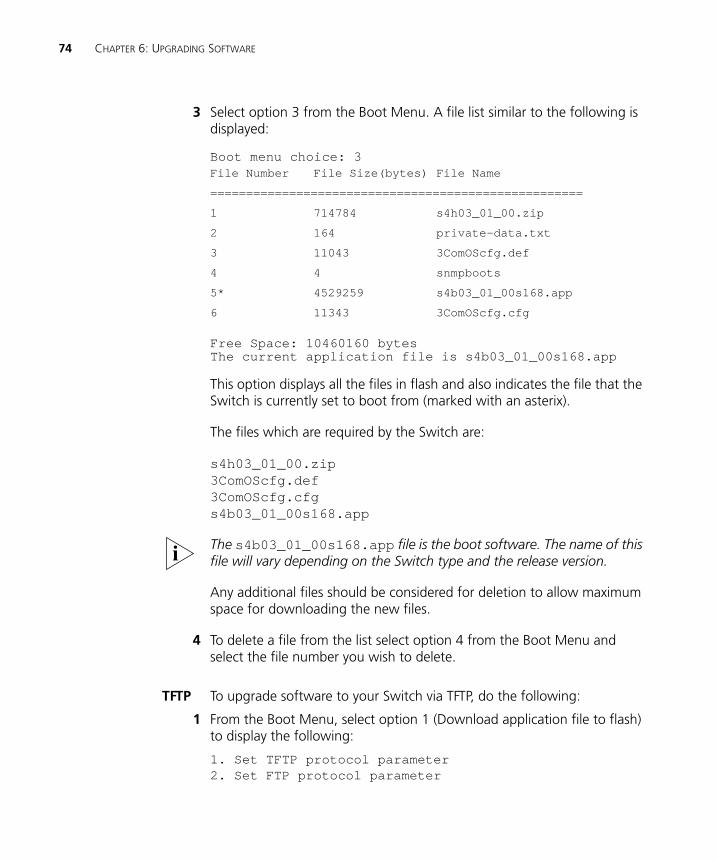
74 CHAPTER 6: UPGRADING SOFTWARE
DUA1715-0AAA02.book Page 74 Wednesday, March 23, 2005 11:17 AM
3 Select option 3 from the Boot Menu. A file list similar to the following is displayed:
Boot menu choice: 3
Free Space: 10460160 bytesThe current application file is s4b03_01_00s168.app
This option displays all the files in flash and also indicates the file that the Switch is currently set to boot from (marked with an asterix).
The files which are required by the Switch are:
s4h03_01_00.zip3ComOScfg.def3ComOScfg.cfgs4b03_01_00s168.app
The s4b03_01_00s168.app file is the boot software. The name of this file will vary depending on the Switch type and the release version.
Any additional files should be considered for deletion to allow maximum space for downloading the new files.
4 To delete a file from the list select option 4 from the Boot Menu and select the file number you wish to delete.
TFTP To upgrade software to your Switch via TFTP, do the following:
1 From the Boot Menu, select option 1 (Download application file to flash) to display the following:
1. Set TFTP protocol parameter2. Set FTP protocol parameter
File Number File Size(bytes) File Name
====================================================
1 714784 s4h03_01_00.zip
2 164 private-data.txt
3 11043 3ComOScfg.def
4 4 snmpboots
5* 4529259 s4b03_01_00s168.app
6 11343 3ComOScfg.cfg
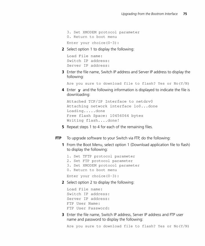
Upgrading from the Bootrom Interface 75
DUA1715-0AAA02.book Page 75 Wednesday, March 23, 2005 11:17 AM
3. Set XMODEM protocol parameter0. Return to boot menu
Enter your choice(0-3):
2 Select option 1 to display the following:
Load File name:Switch IP address:Server IP address:
3 Enter the file name, Switch IP address and Server IP address to display the following:
Are you sure to download file to flash? Yes or No(Y/N)
4 Enter y and the following information is displayed to indicate the file is downloading:
Attached TCP/IP Interface to netdrv0Attaching network interface lo0...doneLoading.....doneFree flash Space: 10456064 bytesWriting flash....done!
5 Repeat steps 1 to 4 for each of the remaining files.
FTP To upgrade software to your Switch via FTP, do the following:
1 From the Boot Menu, select option 1 (Download application file to flash) to display the following:
1. Set TFTP protocol parameter2. Set FTP protocol parameter3. Set XMODEM protocol parameter0. Return to boot menu
Enter your choice(0-3):
2 Select option 2 to display the following:
Load File name:Switch IP address:Server IP address:FTP User Name:FTP User Password:
3 Enter the file name, Switch IP address, Server IP address and FTP user name and password to display the following:
Are you sure to download file to flash? Yes or No(Y/N)
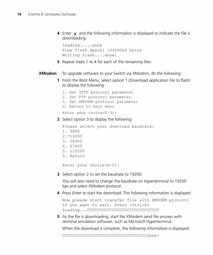
76 CHAPTER 6: UPGRADING SOFTWARE
DUA1715-0AAA02.book Page 76 Wednesday, March 23, 2005 11:17 AM
4 Enter y and the following information is displayed to indicate the file is downloading:
Loading.....doneFree flash Space: 10456064 bytesWriting flash....done!
5 Repeat steps 1 to 4 for each of the remaining files.
XModem To upgrade software to your Switch via XModem, do the following:
1 From the Boot Menu, select option 1 (Download application file to flash) to display the following:
1. Set TFTP protocol parameter2. Set FTP protocol parameter3. Set XMODEM protocol parameter0. Return to boot menu
Enter your choice(0-3):
2 Select option 3 to display the following:
Please select your download baudrate:1. 96002.*192003. 384004. 576005. 1152000. Return
Enter your choice(0-5):
3 Select option 2 to set the baudrate to 19200.
You will also need to change the baudrate on Hyperterminal to 19200 bps and select XModem protocol.
4 Press Enter to start the download. The following information is displayed:
Now please start transfer file with XMODEM protocolIf you want to exit, Press <Ctrl+X>Loading...CCCCCCCCCCCCCCCCCCCCCCCCCCCCC
5 As the file is downloading, start the XModem send file process with terminal emulation software, such as Microsoft Hyperterminal.
When the download is complete, the following information is displayed:
CCCCCCCCCCCCCCCCCCCCCCCCCCCCCCCCCCdone!

Bootrom Upgrade 77
DUA1715-0AAA02.book Page 77 Wednesday, March 23, 2005 11:17 AM
6 Repeat steps 1 to 5 for each of the remaining files.
Bootrom Upgrade This section describes how to indicate which file the Switch is to boot from once the software has been loaded.
1 From the Boot menu, select option 2 to display a file list similar to the following:
Boot menu choice: 2
Free Space: 10460160 bytesThe current application file is s4b03_01_00s168.appPlease input the file number to boot:
2 Select the required file number to boot (in the example it is 5).
Bootrom Upgrade viaTFTP
To upgrade the bootrom firmware from the Boot menu via TFTP do the following:
1 From the Boot menu, select option 6 to display the bootrom upgrade menu as shown:
Bootrom update menu:1. Set TFTP protocol parameter2. Set FTP protocol parameter3. Set XMODEM protocol parameter0. Return to boot menu
Enter your choice(0-3):
2 Select option 1 to display the following:
Load File name:Switch IP address:Server IP address:
File Number File Size(bytes) File Name
====================================================
1 714784 s4h03_01_00.zip
2 164 private-data.txt
3 11043 3ComOScfg.def
4 4 snmpboots
5* 4529259 s4b03_01_00s168.app
6 11343 3ComOScfg.cfg
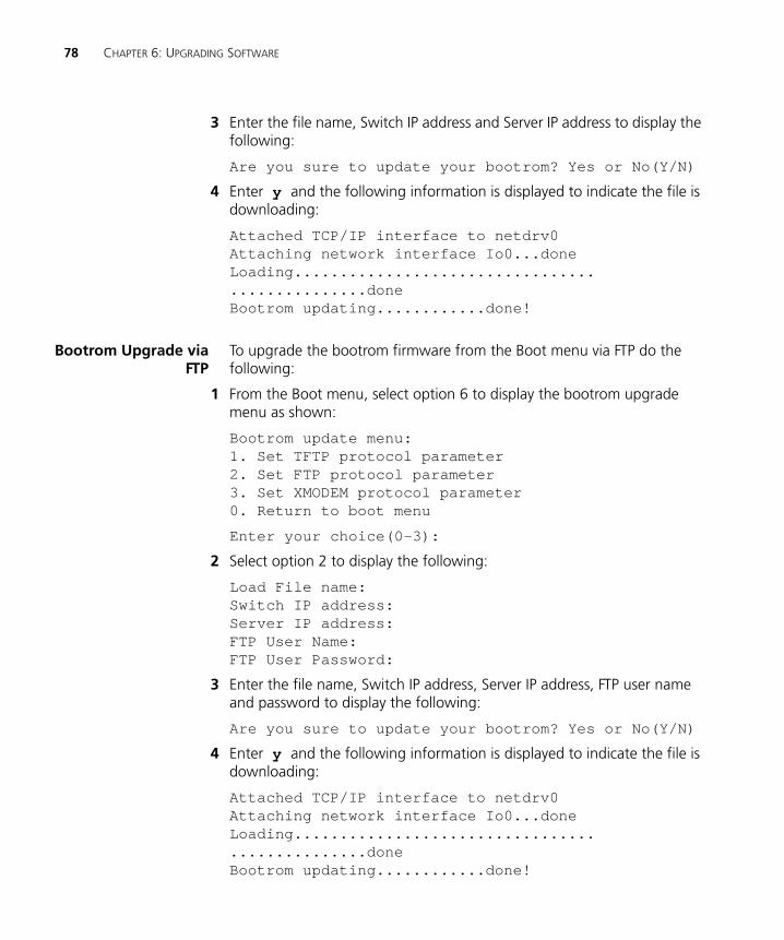
78 CHAPTER 6: UPGRADING SOFTWARE
DUA1715-0AAA02.book Page 78 Wednesday, March 23, 2005 11:17 AM
3 Enter the file name, Switch IP address and Server IP address to display the following:
Are you sure to update your bootrom? Yes or No(Y/N)
4 Enter y and the following information is displayed to indicate the file is downloading:
Attached TCP/IP interface to netdrv0Attaching network interface Io0...doneLoading................................................doneBootrom updating............done!
Bootrom Upgrade viaFTP
To upgrade the bootrom firmware from the Boot menu via FTP do the following:
1 From the Boot menu, select option 6 to display the bootrom upgrade menu as shown:
Bootrom update menu:1. Set TFTP protocol parameter2. Set FTP protocol parameter3. Set XMODEM protocol parameter0. Return to boot menu
Enter your choice(0-3):
2 Select option 2 to display the following:
Load File name:Switch IP address:Server IP address:FTP User Name:FTP User Password:
3 Enter the file name, Switch IP address, Server IP address, FTP user name and password to display the following:
Are you sure to update your bootrom? Yes or No(Y/N)
4 Enter y and the following information is displayed to indicate the file is downloading:
Attached TCP/IP interface to netdrv0Attaching network interface Io0...doneLoading................................................doneBootrom updating............done!
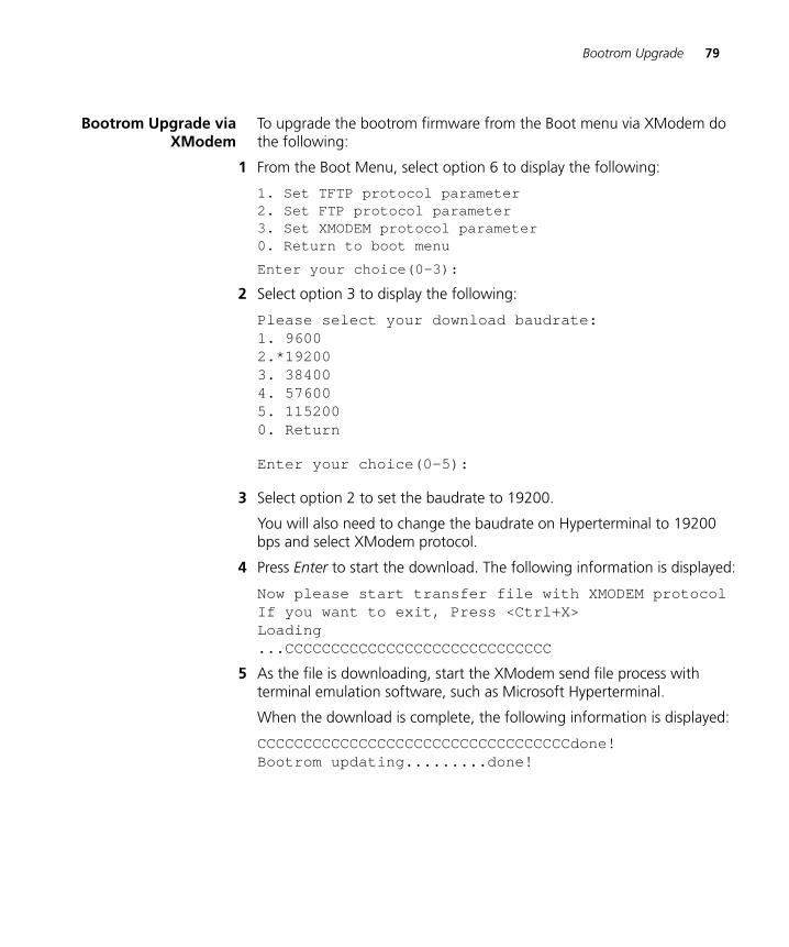
Bootrom Upgrade 79
DUA1715-0AAA02.book Page 79 Wednesday, March 23, 2005 11:17 AM
Bootrom Upgrade viaXModem
To upgrade the bootrom firmware from the Boot menu via XModem do the following:
1 From the Boot Menu, select option 6 to display the following:
1. Set TFTP protocol parameter2. Set FTP protocol parameter3. Set XMODEM protocol parameter0. Return to boot menu
Enter your choice(0-3):
2 Select option 3 to display the following:
Please select your download baudrate:1. 96002.*192003. 384004. 576005. 1152000. Return
Enter your choice(0-5):
3 Select option 2 to set the baudrate to 19200.
You will also need to change the baudrate on Hyperterminal to 19200 bps and select XModem protocol.
4 Press Enter to start the download. The following information is displayed:
Now please start transfer file with XMODEM protocolIf you want to exit, Press <Ctrl+X>Loading...CCCCCCCCCCCCCCCCCCCCCCCCCCCCC
5 As the file is downloading, start the XModem send file process with terminal emulation software, such as Microsoft Hyperterminal.
When the download is complete, the following information is displayed:
CCCCCCCCCCCCCCCCCCCCCCCCCCCCCCCCCCdone!Bootrom updating.........done!

80 CHAPTER 6: UPGRADING SOFTWARE
DUA1715-0AAA02.book Page 80 Wednesday, March 23, 2005 11:17 AM
DUA1715-0AAA02.book Page 81 Wednesday, March 23, 2005 11:17 AM
A
SAFETY INFORMATIONYou must read the following safety information before carrying out any installation or removal of components, or any maintenance procedures on the Switch 5500.
WARNING: Warnings contain directions that you must follow for your personal safety. Follow all directions carefully.You must read the following safety information carefully before you install or remove the unit.
AVERTISSEMENT: Les avertissements présentent des consignes que vous devez respecter pour garantir votre sécurité personnelle. Vous devez respecter attentivement toutes les consignes. Nous vous demandons de lire attentivement les consignes suivantes de sécurité avant d’installer ou de retirer l’appareil.
VORSICHT: Warnhinweise enthalten Anweisungen, die Sie zu Ihrer eigenen Sicherheit befolgen müssen. Alle Anweisungen sind sorgfältig zu befolgen.Sie müssen die folgenden Sicherheitsinformationen’ sorgfältig durchlesen, bevor Sie das Gerät installieren oder ausbauen.
ADVERTENCIA: Las advertencias contienen indicaciones que debe respetar por su seguridad personal.Siga las indicaciones con cuidado. Antes de instalar o extraer la unidad, debe leer detenidamente la siguiente información de seguridad.
AVVERTENZA: le avvertenze contengono istruzioni indispensabili per assicurare la sicurezza personale. Seguire attentamente tutte le indicazioni fornite. Prima di installare o rimuovere l'unità, leggere attentamente le seguenti informazioni di sicurezza.
OSTRZEŻENIE: Ostrzeżenia zawierają wskazówki, których należy przestrzegać dla własnego bezpieczeństwa. Należy uważnie przestrzegać wszystkich wskazówek. Przed instalacją lub demontażem
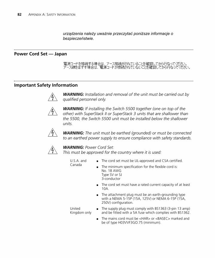
82 APPENDIX A: SAFETY INFORMATION
DUA1715-0AAA02.book Page 82 Wednesday, March 23, 2005 11:17 AM
urządzenia należy uważnie przeczytać poniższe informacje o bezpieczeństwie.
Power Cord Set — Japan
Important Safety Information
WARNING: Installation and removal of the unit must be carried out by qualified personnel only.
WARNING: If installing the Switch 5500 together (one on top of the other) with SuperStack II or SuperStack 3 units that are shallower than the 5500, the Switch 5500 unit must be installed below the shallower units.
WARNING: The unit must be earthed (grounded) or must be connected to an earthed power supply to ensure compliance with safety standards.
WARNING: Power Cord Set:This must be approved for the country where it is used:
U.S.A. and Canada
■ The cord set must be UL-approved and CSA certified.
■ The minimum specification for the flexible cord is:No. 18 AWGType SV or SJ3-conductor
■ The cord set must have a rated current capacity of at least 10A.
■ The attachment plug must be an earth-grounding type with a NEMA 5-15P (15A, 125V) or NEMA 6-15P (15A, 250V) configuration.
United Kingdom only
■ The supply plug must comply with BS1363 (3-pin 13 amp) and be fitted with a 5A fuse which complies with BS1362.
■ The mains cord must be <HAR> or <BASEC> marked and be of type H03VVF3GO.75 (minimum).
Important Safety Information 83
DUA1715-0AAA02.book Page 83 Wednesday, March 23, 2005 11:17 AM
WARNING: The appliance coupler (the connector to the unit and not the wall plug) must have a configuration for mating with an EN60320/IEC320 appliance inlet.
WARNING: The socket outlet must be near to the unit and easily accessible.
WARNING: This unit operates under SELV (Safety Extra Low Voltage) conditions according to IEC 60950. The conditions are only maintained if the equipment to which it is connected also operates under SELV conditions.
WARNING: France and Peru only:This unit cannot be powered from IT† supplies. If your supplies are of IT type, this unit must be powered by 230V (2P+T) via an isolation transformer ratio 1:1, with the secondary connection point labelled Neutral, connected directly to earth (ground).†Impédance à la terre.
WARNING: U.K. only:If connecting a modem to the console port of the Switch 5500, only use a modem which is suitable for connection to the telecommunications system.
WARNING: RJ-45 Ports. These are shielded RJ-45 data sockets. They cannot be used as standard traditional telephone sockets, or to connect the unit to a traditional PBX or public telephone network. Only connect RJ-45 data connectors, network telephony systems, or network telephones to these sockets.
Either shielded or unshielded data cables with shielded or unshielded jacks can be connected to these data sockets.
WARNING: Fiber Optic ports – Optical Safety
Europe only: ■ The supply plug must comply with CEE 7/7 (“SCHUKO”).
■ The mains cord must be <HAR> or <BASEC> marked and be of type H03VVF3GO.75 (minimum).
Denmark ■ The supply plug must comply with section 107-2-D1, standard DK2-1a or DK2-5a.
Switzerland ■ The supply plug must comply with SEV/ASE 1011.
84 APPENDIX A: SAFETY INFORMATION
DUA1715-0AAA02.book Page 84 Wednesday, March 23, 2005 11:17 AM
Never look at the transmit laser through a magnifying device while it is powered on. Never look directly at the fiber TX port and fiber cable ends when they are powered on.
WARNING: This device has more than one power input. Disconnect all power inputs to power off this device.
WARNING: The installation of the Redundant Power Supply (RPS) should only be carried out by properly trained and qualified personnel.
WARNING: These instructions must be read in conjunction with the RPS flyer and the safety and installation instructions supplied with your RPS.
WARNING: When powering any Switch 5500 from an RPS, the unit must be earthed (grounded). This can be achieved by either connecting the power cord to the unit or by connecting the earth terminal on the rear of the unit to a reliable electrical earth, or by connecting both. It must be ensured that the earth connection is made before connecting the DC supply from the RPS.
WARNING: Any RPS must be approved as an unearthed SELV output in accordance with IEC 60950-1/UL 60950-1/EN 60950-1.
WARNING: The characteristics of the Switch 5500 DC supply input are given in Appendix C on page 105.
WARNING: RPS Manufacturers recommendations must be followed when connecting the cable to the RPS.
WARNING: Ensure that the circuit breaker in the RPS is in the open (off) position when connecting the cable to the RPS.
WARNING: You must ensure that the positive terminal on the Switch is connected to the positive (common) terminal of the RPS and that the negative terminal on the Switch is connected to the negative (circuit breaker) terminal of the RPS.
Class 1
LASER PRODUCT
L’information de Sécurité Importante 85
DUA1715-0AAA02.book Page 85 Wednesday, March 23, 2005 11:17 AM
WARNING: Ensure that the circuit breaker in the RPS is in the open (off) position when connecting the RPS cable and connector to the Switch.
L’information de Sécurité Importante
AVERTISSEMENT: L'installation et la dépose de ce groupe doivent être confiés à un personnel qualifié.
AVERTISSEMENT: Si vous entassez l'unité Switch avec les unités SuperStack 4 Hub, l'unité Switch 5500 doit être installée en dessous des unités Hub plus étroites.
AVERTISSEMENT: Vous devez mettre l’appareil à la terre (à la masse) ce groupe.
AVERTISSEMENT: Brancher l’unité à une source de courant mise à la terre pour assurer la conformité aux normes de sécurité.
AVERTISSEMENT: Cordon électrique:Il doit être agréé ans le pays d'utilisation:
Etats-Unis et Canada
■ Le cordon doit avoir reçu l'homologation des UL et un certificat de la CSA
■ Le cordon souple doit respecter, à titre minimum, les spécifications suivantes :
■ calibre 18 AWG
■ type SV ou SJ
■ à 3 conducteurs
■ Le cordon doit être en mesure d'acheminer un courant nominal d'au moins 10 A
■ La prise femelle de branchement doit être du type à mise à la terre (mise à la masse) et respecter la configuration NEMA 5-15P (15 A, 125 V) ou NEMA 6-15P (15 A, 250 V)
Danemark ■ La prise mâle d'alimentation doit respecter la section 107-2 D1 de la norme DK2 1a ou DK2 5a
Europe ■ La prise secteur doit être conforme aux normes CEE 7/7 (“SCHKO”)
■ LE cordon secteur doit porter la mention <HAR> ou <BASEC> et doit être de type HO3VVF3GO.75 (minimum).
Suisse ■ La prise mâle d'alimentation doit respecter la norme SEV/ASE 1011
86 APPENDIX A: SAFETY INFORMATION
DUA1715-0AAA02.book Page 86 Wednesday, March 23, 2005 11:17 AM
AVERTISSEMENT: Le coupleur d'appareil (le connecteur du groupe et non pas la prise murale) doit respecter une configuration qui permet un branchement sur une entrée d'appareil EN60320/CEI 320.
AVERTISSEMENT: La prise secteur doit se trouver à proximité de l’appareil et son accès doit être facile.
AVERTISSEMENT: L’appareil fonctionne à une tension extrêmement basse de sécurité qui est conforme à la norme CEI 60950. Ces conditions ne sont maintenues que si l'équipement auquel il est raccordé fonctionne dans les mêmes conditions.
AVERTISSEMENT: France et Pérou uniquement:Ce groupe ne peut pas être alimenté par un dispositif à impédance à la terre. Si vos alimentations sont du type impédance à la terre, ce groupe doit être alimenté par une tension de 230 V (2 P+T) par le biais d'un transformateur d'isolement à rapport 1:1, avec un point secondaire de connexion portant l'appellation Neutre et avec raccordement direct à la terre (masse).
AVERTISSEMENT: Points d’accès RJ-45. Ceux-ci sont protégés par des prises de données. Ils ne peuvent pas être utilisés comme prises de téléphone conventionnelles standard, ni pour la connection de l’unité à un réseau téléphonique central privé ou public. Raccorder seulement connecteurs de données RJ-45, systèmes de réseaux de téléphonie ou téléphones de réseaux à ces prises.
Il est possible de raccorder des câbles protégés ou non protégés avec des jacks protégés ou non protégés à ces prises de données.
AVERTISSEMENT: Ports pour fibres optiques – sécurité sur le plan optique.
Ne regardez jamais le laser tant qu'il est sous tension. Ne regardez jamais directement le port à fibres optiques et les embouts de câbles à fibres optiques tant qu'ils sont sous tension.
Dispositif Laser
de Classe 1
L’information de Sécurité Importante 87
DUA1715-0AAA02.book Page 87 Wednesday, March 23, 2005 11:17 AM
AVERTISSEMENT: Ce périphérique comporte plusieurs entrées d'alimentation. Déconnectez toutes les entrées d'alimentation afin de le mettre hors tension.
AVERTISSEMENT: L'installation du RPS (Redundant Power Supply) ne doit être confiée qu'à un personnel formé et qualifié.
AVERTISSEMENT: Ces instructions doivent être lues conjointement avec les instructions d'installation et les consignes de sécurité qui accompagnent le RPS.
AVERTISSEMENT: Lorsqu'un commutateur Switch 5500 est alimenté par un module RPS, l'unité doit être mise à la terre. Pour cela, branchez le cordon d'alimentation à l'unité ou branchez la borne de mise à la terre située à l'arrière de l'unité à une prise de terre fiable, ou procédez aux deux raccordements. Assurez-vous que l'unité est mise à la terre avant de raccorder l'alimentation CC du RPS.
AVERTISSEMENT: Le RPS doit être approuvé en tant que sortie SELV non reliée à la terre, conformément à la norme IEC 60950-1/UL 60950-1/EN 60950-1.
AVERTISSEMENT: Ces instructions doivent être lues conjointement avec les caractéristiques de l'alimentation CC du Switch 5500 fournies en annexe C, Spécifications techniques.
AVERTISSEMENT: Vous devez respecter les recommandations du fabricant lors du branchement du câble au module RPS.
AVERTISSEMENT: Assurez-vous que le disjoncteur du RPS est ouvert (off) lors du branchement du câble au RPS.
AVERTISSEMENT: Assurez-vous de brancher la borne positive du commutateur à la borne positive (commune) du RPS, et la borne négative du commutateur à la borne négative (disjoncteur) du RPS.
AVERTISSEMENT: Assurez-vous que le disjoncteur du RPS est ouvert (off) lors du branchement du câble et du connecteur du RPS au commutateur 3Com.
88 APPENDIX A: SAFETY INFORMATION
DUA1715-0AAA02.book Page 88 Wednesday, March 23, 2005 11:17 AM
Wichtige Sicherheitsinformationen
VORSICHT: Alle Verfahren die in dieser Anleitung beschrieben werden gelten für alle Modelle, sofern nicht anders angegeben. Wo eine Vorgehensweise für die Schalter 5500-SI 24 und Schalter 5500-SI 52 gilt wird nur der Begriff Schalter verwendet.
Diese Anleitung ist für Netzwerkadministratoren vorgesehen, die für die Installation und das Einstellen von Netzwerkkomponenten verantwortlich sind; Erfahrung im Umgang mit LANs (Local Area Networks) wird
VORSICHT: Die Installation und der Ausbau des Geräts darf nur durch Fachpersonal erfolgen.
VORSICHT: Wenn die Switch 5500 Einheit in einer Stapel mit anderen SuperStack 4 Hub Einheiten eingebaut werden soll, muß die Switch 5500 Einheit unter die schmaleren Hub Einheiten eingebaut werden.
VORSICHT: Das Gerät muß geerdet sein.
VORSICHT: Das Gerät muß an eine geerdete Steckdose angeschlossen werden, die europäischen Sicherheitsnormen erfüllt.
VORSICHT: Der Anschlußkabelsatz muß mit den Bestimmungen des Landes übereinstimmen, in dem er verwendet werden soll.
VORSICHT: Der Gerätestecker (der Anschluß an das Gerät, nicht der Wandsteckdosenstecker) muß eine passende Konfiguration für einen Geräteeingang gemäß EN60320/IEC320 haben.
VORSICHT: Die Netzsteckdose muß in der Nähe des Geräts und leicht zugänglich sein. Die Stromversorgung des Geräts kann nur durch Herausziehen des Gerätenetzkabels aus der Netzsteckdose unterbrochen werden.
VORSICHT: Europe
■ Das Netzkabel muß vom Typ HO3VVF3GO.75 (Mindestanforderung) sein und die Aufschrift <HAR> oder <BASEC> tragen.
■ Der Netzstecker muß die Norm CEE 7/7 erfüllen (”SCHUKO”).
Wichtige Sicherheitsinformationen 89
DUA1715-0AAA02.book Page 89 Wednesday, March 23, 2005 11:17 AM
VORSICHT: Der Betrieb dieses Geräts erfolgt unter den SELV-Bedingungen (Sicherheitskleinstspannung) gemäß IEC 60950. Diese Bedingungen sind nur gegeben, wenn auch die an das Gerät angeschlossenen Geräte unter SELV-Bedingungen betrieben werden.
VORSICHT: RJ-45-Porte. Diese Porte sind geschützte Datensteckdosen. Sie dürfen weder wie normale traditionelle Telefonsteckdosen noch für die Verbindung der Einheit mit einem traditionellem privatem oder öffentlichem Telefonnetzwerk gebraucht werden. Nur RJ-45-Datenanscluße, Telefonnetzsysteme or Netztelefone an diese Steckdosen anschließen.
Entweder geschützte oder ungeschützte Buchsen dürfen an diese Datensteckdosen angeschlossen werden.
VORSICHT: Faseroptikanschlüsse – Optische Sicherheit.
Niemals ein Übertragungslaser betrachten, während dieses eingeschaltet ist. Niemals direkt auf die Faseransnchlüsse und auf die Faserkabelenden schauen, während diese eingeschaltet sind.
VORSICHT: Dieses Gerät besitzt mehrere Eingänge zur Stromversorgung. Trennen Sie das Gerät zum Ausschalten von allen Stromquellen.
VORSICHT: Die RPS (Redundant Power Supply, redundante Stromversorgung) darf nur von entsprechend geschultem und qualifiziertem Fachpersonal installiert werden.
VORSICHT: Diese Anleitungen müssen im Zusammenhang mit den Sicherheitshinweisen und Installationsanleitungen zu Ihrer RPS gelesen werden.
VORSICHT: Bei der Stromversorgung eines Switch 5500 über eine RPS muss das Gerät geerdet sein. Hierfür kann entweder das Netzkabel an das Gerät angeschlossen werden oder die Erdungsklemme an der Rückseite des Geräts mit einer zuverlässigen elektrischen Erdung verbunden werden oder beides. Es ist sicherzustellen, dass die
Laser Gerät
der Klasse 1
90 APPENDIX A: SAFETY INFORMATION
DUA1715-0AAA02.book Page 90 Wednesday, March 23, 2005 11:17 AM
Erdungsverbindung vor dem Anschließen der von der RPS bereitgestellten Gleichstromversorgung hergestellt wird.
VORSICHT: Jede RPS muss als nicht geerdetes SELV-Ausgangsgerät gemäß IEC 60950-1/UL 60950-1/EN 60950-1 zugelassen sein.
VORSICHT: Diese Anleitungen müssen im Zusammenhang mit den Eigenschaften des Gleichstrom-Versorgungseingangs des Switch 5500 gelesen werden, die in Anhang C, "Technische Daten", aufgeführt sind.
VORSICHT: Beim Anschließen des Kabels an die RPS sind die Empfehlungen des Herstellers zu beachten.
VORSICHT: Stellen Sie sicher, dass sich der Schutzschalter an der RPS beim Anschließen des Kabels an die RPS in der geöffneten Stellung (Aus) befindet.
VORSICHT: Stellen Sie auf jeden Fall sicher, dass die positive Klemme am Switch an die positive (gemeinsame) Klemme der RPS und die negative Klemme am Switch an die negative (gemeinsame) Klemme der RPS angeschlossen wird.
VORSICHT: Stellen Sie sicher, dass sich der Schutzschalter an der RPS beim Anschließen des RPS-Kabels und des Steckers des 3Com Switch in der geöffneten Stellung (Aus) befindet.
Información de Seguridad Importante
ADVERTENCIA: La instalación o la extracción de la unidad sólo debe llevarla a cabo personal cualificado.
ADVERTENCIA: Si instala el 5500 en una pila con unidades SuperStack II o SuperStack 3 que son más estrechas que el 5500, la unidad 5500 debe instalarse debajo de las unidades más estrechas.
ADVERTENCIA: La unidad debe tener toma de tierra (conectado a tierra).
ADVERTENCIA: Conecte la unidad a una fuente de alimentación con toma de tierra para garantizar el cumplimiento de las normas de seguridad.
Información de Seguridad Importante 91
DUA1715-0AAA02.book Page 91 Wednesday, March 23, 2005 11:17 AM
ADVERTENCIA: Conjunto de cables eléctricos:Debe estar homologado para el país donde se utilice:
ADVERTENCIA: El acoplador del equipo (el conector para la unidad y no la toma de la pared) debe tener una configuración que se adapte a una entrada del equipo EN60320/IEC320.
ADVERTENCIA: El enchufe debe estar cerca de la unidad y ser de fácil acceso.
ADVERTENCIA: Esta unidad funciona en condiciones SELV (voltaje extrabajo de seguridad) de conformidad con la norma IEC 60950. Las condiciones sólo se mantienen si el equipo al que esté conectada la unidad también funciona en condiciones SELV.
ADVERTENCIA: Sólo para Francia y Perú: esta unidad no puede recibir corriente de fuentes IT†. Si las fuentes de suministro de corriente son de tipo IT, esta unidad debe recibir 230 V (2P+T) a través de un transformador aislador con relación 1:1, con el punto de conexión
EE.UU. y Canadá
■ El conjunto de cables debe estar homologado por UL y tener la certificación CSA.
■ La especificación mínima del cable flexible es: Nº 18 AWG Tipo SV o SJ Tres conductores
■ El conjunto de cables debe tener una capacidad de corriente nominal de al menos 10 A.
■ El enchufe de conexión debe ser de tipo de toma de tierra con una configuración NEMA 5-15P (15 A, 125 V) o NEMA 6-15P (15 A, 250 V).
Sólo para el Reino Unido
■ La toma de alimentación debe cumplir la norma BS1363 (3 patillas, 13 A) e instalarse con un fusible de 5 A que cumpla BS1362.
■ El cable de alimentación de red debe tener la marca <HAR> o <BASEC> y ser de tipo H03VVF3GO.75 (mínimo).
Sólo para Europa:
■ La toma de alimentación debe cumplir la norma CEE 7/7 ("SCHUKO").
■ El cable de alimentación de red debe tener la marca <HAR> o <BASEC> y ser de tipo H03VVF3GO.75 (mínimo).
Dinamarca ■ La toma de alimentación debe cumplir la sección 107-2-D1 de la norma DK2-1a o DK2-5a
Suiza ■ La toma de alimentación debe cumplir la norma SEV/ASE 1011.
92 APPENDIX A: SAFETY INFORMATION
DUA1715-0AAA02.book Page 92 Wednesday, March 23, 2005 11:17 AM
secundario etiquetado como neutro conectado directamente a tierra. †Impédance à la terre.
ADVERTENCIA: Sólo para el Reino Unido: si conecta un módem al puerto de consola del 5500, utilice sólo un módem que sea adecuado para la conexión con el sistema de telecomunicaciones.
ADVERTENCIA: Puertos RJ-45. Son conectores de datos RJ-45 blindados. No pueden utilizarse como tomas de teléfono tradicionales estándar ni para conectar la unidad a una central de conmutación PBX tradicional ni a una red telefónica pública. Conecte sólo conectores de datos RJ-45, sistemas de telefonía de red local o teléfonos de red local a estas tomas. Pueden conectarse cables de datos blindados o sin blindaje con clavijas blindadas o sin blindaje a estos conectores de datos.
ADVERTENCIA: Puertos de fibra óptica: seguridad óptica
No mire nunca al láser de transmisión mientras esté encendido. No mire nunca directamente al puerto de transmisión de fibra óptica ni a los extremos del cable de fibra óptica mientras estén conectados.
ADVERTENCIA: Este dispositivo dispone de más de una entrada de alimentación. Desconecte todas las entradas de alimentación del dispositivo.
ADVERTENCIA: La instalación del sistema de alimentación superflua (RPS) sólo debería llevarla a cabo personal cualificado y con la debida formación.
ADVERTENCIA: Estas instrucciones deben leerse junto con las instrucciones de instalación y seguridad que se facilitan con el sistema RPS.
ADVERTENCIA: al encender cualquier Switch 5500 desde un RPS, la unidad debe contar con una toma de tierra (conexión a tierra). Esto se puede conseguir conectando el cable de alimentación de la unidad o bien conectando el terminal de tierra en la parte posterior de la unidad a una
DISPOSITIVO LÁSERDE CLASE 1
Importanti Informazioni di Sicurezza 93
DUA1715-0AAA02.book Page 93 Wednesday, March 23, 2005 11:17 AM
toma de tierra fiable, o conectando ambas. Deberá asegurarse de que la conexión a tierra se realiza antes de conectar el suministro de CC del RPS.
ADVERTENCIA: Todos los RPS deben estar homologados como salidas SELV sin toma de tierra según IEC 60950-1/UL 60950-1/EN 60950-1.
ADVERTENCIA: Estas instrucciones deben leerse junto con las características de la entrada de suministro de CC del Switch 5500 del Apéndice C, Especificaciones técnicas.
ADVERTENCIA: al conectar el cable al RPS deberán seguirse las recomendaciones del fabricante.
ADVERTENCIA: asegúrese de que el disyuntor del RPS se encuentra en la posición de abierto (desactivado) al conectar el cable al RPS.
ADVERTENCIA: deberá asegurarse de que el terminal positivo del Switch está conectado al terminal positivo (común) del RPS, y de que el terminal negativo del Switch está conectado al terminal negativo (disyuntor) del RPS.
ADVERTENCIA: asegúrese de que el disyuntor del RPS se encuentra en la posición de abierto (desactivado) al conectar el cable del RPS y el conector al Switch 3Com.
Importanti Informazioni di Sicurezza
AVVERTENZA: Le operazioni di installazione e rimozione dell'unità devono essere eseguite esclusivamente da personale qualificato.
AVVERTENZA: Se si installa lo 5500 in uno stack con unità SuperStack II o SuperStack 3 più strette del modello 5500, posizionare lo 5500 sotto tali unità.
AVVERTENZA: L'unità deve disporre di messa a terra.
AVVERTENZA: Per rispettare gli standard di sicurezza, è necessario collegare l'unità a una fonte di alimentazione dotata di messa a terra.
94 APPENDIX A: SAFETY INFORMATION
DUA1715-0AAA02.book Page 94 Wednesday, March 23, 2005 11:17 AM
AVVERTENZA: Set dei cavi di alimentazioneDeve essere approvato per il paese in cui viene utilizzato.
AVVERTENZA: L'accoppiatore (il connettore all'unità e non la spina a muro) deve avere una configurazione abbinabile a una presa EN60320/IEC320.
AVVERTENZA: La presa deve trovarsi vicino all'unità ed essere facilmente accessibile.
AVVERTENZA: Questa unità funziona alle condizioni SELV (Safety Extra Low Voltage) previste dalla norma IEC 60950. Tali condizioni sono mantenute solo se anche l'apparecchiatura a cui è collegata opera nelle stesse condizioni.
AVVERTENZA: Solo per Francia e Perù. Questa unità non può ricevere alimentazione di tipo IT†. Se l'alimentazione è di tipo IT, l'unità deve essere alimentata a 230 V (2P+T) tramite un trasformatore di isolamento con rapporto 1:1, con il punto di collegamento secondario
Stati Uniti e Canada
■ Il cavo deve avere l'approvazione UL e la certificazione CSA
■ La specifica minima per il cavo flessibile è: N. 18 AWG Tipo SV o SJ 3 conduttori
■ Il set di cavi deve avere una capacità nominale di almeno 10 A.
■ La spina di collegamento deve essere dotata di messa a terra, con configurazione NEMA 5-15P (15 A, 125 V) o NEMA 6-15P (15 A, 250 V).
Solo Regno Unito
■ La spina di alimentazione deve essere conforme BS1363 (3 pin 13 amp) e dotata di un fusibile da 5 A conforme BS1362.
■ Il cavo dell'alimentazione di rete deve essere contrassegnato dai marchi <HAR> o <BASEC> ed essere di tipo H03VVF3GO.75 (minimo).
Solo Europa ■ La spina di alimentazione deve essere conforme CEE 7/7 (tipo "SCHUKO").
■ Il cavo dell'alimentazione di rete deve essere contrassegnato dai marchi <HAR> o <BASEC> ed essere di tipo H03VVF3GO.75 (minimo).
Danimarca ■ La spina di alimentazione deve essere conforme alla sezione 107-2-D1, standard DK2-1a o DK2
Svizzera ■ La spina di alimentazione deve essere conforme SEV/ASE 1011
Importanti Informazioni di Sicurezza 95
DUA1715-0AAA02.book Page 95 Wednesday, March 23, 2005 11:17 AM
contrassegnato come Neutro, collegato direttamente a terra. †Impédance à la terre.
AVVERTENZA: Solo Regno Unito. Se si collega un modem alla porta Console dello 5500, utilizzare solo un modem idoneo per il collegamento con il sistema di telecomunicazioni.
AVVERTENZA: Le porte RJ-45 sono prese dati RJ-45 schermate. Non è pertanto possibile utilizzarle come normali prese telefoniche né per collegare l'unità a un PBX (Private Branch Exchange, centralino telefonico privato) o a una rete telefonica pubblica. Collegare a queste porte solo prese dati RJ-45, sistemi di telefonia o telefoni di rete. A queste prese dati è possibile collegare cavi dati schermati o non schermati con prese dati schermate o non schermate.
AVVERTENZA: Porte a fibre ottiche - Protezione degli occhi
Non guardare mai il laser di trasmissione attraverso uno strumento ottico di ingrandimento quando è acceso. Non guardare mai direttamente la porta TX a fibre ottiche e le estremità del cavo a fibre ottiche quando sono accese.
AVVERTENZA: Il dispositivo presenta più punti di alimentazione. Per spegnere il dispositivo, scollegare tutti i punti di alimentazione.
AVVERTENZA: le operazioni di installazione dell'RPS (Redundant Power Supply) devono essere eseguite esclusivamente da personale qualificato e opportunamente addestrato.
AVVERTENZA: queste istruzioni devono essere lette insieme alle istruzioni di sicurezza e installazione fornite con l'RPS.
AVVERTENZA: se si accende uno Switch 5500 da un RPS, l'unità deve disporre di messa a terra. Per accendere lo switch, è possibile collegare il cavo di alimentazione all'unità, collegare il terminale di terra situato sul retro dell'unità a una presa elettrica di terra sicura oppure collegarli
PRODOTTO LASER
CLASSE 1
96 APPENDIX A: SAFETY INFORMATION
DUA1715-0AAA02.book Page 96 Wednesday, March 23, 2005 11:17 AM
entrambi. Prima di collegare l'alimentazione CC dell'RPS, è necessario verificare la messa a terra.
AVVERTENZA: tutti gli RPS devono essere approvati come dispositivi di uscita SELV non messi a terra in conformità con le norme IEC 60950-1/UL 60950-1/EN 60950-1.
AVVERTENZA: queste istruzioni devono essere lette insieme ai valori di ingresso dell'alimentazione CC dello Switch 5500 che vengono forniti nell'Appendice C, Specifiche tecniche.
AVVERTENZA: quando si collega il cavo all'RPS, si consiglia di rispettare le raccomandazioni fornite dal fabbricante.
AVVERTENZA: durante il collegamento del cavo all'RPS, verificare che il salvavita dell'RPS si trovi in posizione Acceso (spento).
AVVERTENZA: è necessario verificare che il polo positivo sullo switch sia collegato al polo positivo (comune) dell'RPS e che il polo negativo sullo switch sia collegto al polo negativo (salvavita) dell'RPS.
AVVERTENZA: prima di collegare il cavo RPS e il connettore allo switch 3Com, verificare che il salvavita si trovi in posizione Acceso (spento).
Ważne informacje o zabezpieczeniach
OSTRZEŻENIE: Instalacja i demontaż urządzenia mogą być wykonywane tylko przez wykwalifikowany personel.
OSTRZEŻENIE: Podczas instalacji Switch 5500 w stosie z urządzeniami SuperStack II lub SuperStack 3, które są węższe niż Switch 5500, urządzenie Switch 5500 musi być zainstalowane pod węższym urządze-niem.
OSTRZEŻENIE: Urządzenie musi być uziemione lub musi być podłączone do uziemionego źródła zasilania w celu zapewnienia zgod-ności z wymogami bezpieczeństwa.
OSTRZEŻENIE: Zestaw przewodów zasilania:
Wa¿ne informacje o zabezpieczeniach 97
DUA1715-0AAA02.book Page 97 Wednesday, March 23, 2005 11:17 AM
Niezbędna jest zgodność z przepisami kraju, w którym jest stosowany:
OSTRZEŻENIE: Złączka urządzenia (podłączona do przełącznika, a nie do wtyczki ściennej) musi być odpowiednio dopasowana do normy EN60320/IEC320 otworu wlotowego.
OSTRZEŻENIE: Gniazdo zasilające musi być umieszczone w pobliżu urządzenia i musi być łatwo dostępne.
OSTRZEŻENIE: Urządzenie to pracuje w warunkach SELV (Safety Extra Low Voltage – Bezpieczne niskie napięcie) zgodnie z normą IEC 60950. Takie warunki są zachowane tylko, jeśli osprzęt, do którego jest podłączone, również pracuje w warunkach SELV.
OSTRZEŻENIE: Sólo para Francia y Perú:Esta unidad no puede recibir corriente de fuentes IT†. Si las fuentes de suministro de corriente son de tipo IT, esta unidad debe recibir 230V (2P+T) a través de un transformador aislador con relación 1:1, con el pun-to de conexión secundario etiquetado como neutro conectado directa-
Stany Zjednoczone i Kanada
■ Zestaw przewodów musi posiadać zezwolenie UL oraz certyfikat CSA.
■ Minimalna specyfikacja przewodu giętkiego: Przewód typu SV lub SJ 3 o średnicy 18 wg specyfikacji AWG.
■ Zestaw przewodów musi posiadać pojemność prądu znamionowego przynajmniej 10A.
■ Wtyczka musi być uziemiająca z układem typu NEMA 5-15P (15A, 125V) lub NEMA 6-15P (15A, 250V).
Wielka Brytania ■ Wtyczka musi być zgodna z normą BS1363 (3-pinowa 13 amperów) i musi być wyposażona w bezpiecznik 5A zgodny z normą BS1362.
■ Przewód sieci zasilającej musi być oznaczony <HAR> lub <BASEC> i musi być typu H03VVF3g0.75 (minimum).
Europa ■ Wtyczka zasilająca musi być zgodna z normą CEE 7/7 („SCHUKO”).
■ Przewód sieci zasilającej musi być oznaczony <HAR> lub <BASEC> i musi być typu H03VVF3g0.75 (minimum).
Dania ■ Wtyczka zasilająca musi być zgodna z sekcją 107-2-D1 normy DK2-1a lub DK2-5a.
Szwajcaria ■ Wtyczka zasilająca musi być zgodna z normą SEV/ASE 1011.
98 APPENDIX A: SAFETY INFORMATION
DUA1715-0AAA02.book Page 98 Wednesday, March 23, 2005 11:17 AM
mente a tierra. †Impédance ŕ la terre.
OSTRZEŻENIE: Tylko Wielka Brytania: Podczas podłączania modemu do portu konsoli Switch 5500 należy stosować tylko modem odpowiedni do podłączenia do sieci telekomuni-kacyjnej.
OSTRZEŻENIE: Porty RJ-45. Są to ekranowane gniazda danych RJ-45. Nie mogą być używane jako tradycyjne gniazda telekomunikacyjne lub stosowane do podłączenia urządzenia do publicznej sieci telefonicznej lub centrali PBX. Do tych gniazd należy podłączać jedynie łącza danych RJ-45, sieciowe systemy telefoniczne lub telefony sieciowe. Zarówno osłonięte, jak i nieosłonięte przewody z danymi wraz z osłoniętymi lub nieosłoniętymi wtykami mogą być podłączone do tych gniazd.
OSTRZEŻENIE: Porty światłowodowe – bezpieczeństwo
Nie wolno nigdy patrzeć na włączoną diodę laser transmisyjny przez urządzenie wzmacniające. Nie wolno nigdy patrzeć bezpośrednio na port włókna TX i końcówki światłowodów, jeśli są zasilane.
OSTRZEŻENIE: To urządzenie ma kilka punktów podłączenia zasilania. Aby wyłączyć urządzenie, należy odłączyć wszystkie punkty zasilania.
OSTRZEŻENIE: Instalacja zasilacza nadmiarowego (RPS) powinna być wykonywana przez odpowiednio przeszkolony i wykwalifikowany person-el.
OSTRZEŻENIE: Te instrukcje należy przeczytać razem z instrukcjami dotyczącymi bezpieczeństwa i instalacji dostarczonymi z systemem zasi-lania nadmiarowego.
OSTRZEŻENIE: Jeśli dowolny przełącznik Switch 5500 jest zasilany z zasilacza RPS, urządzenie musi być uziemione. Można to uzyskać przez podłączenie przewodu zasilającego do urządzenia lub przez podłączenie końcówki uziemienia z tyłu urządzenia do dobrego elementu uziemi-ającego. Należy upewnić się, że urządzenie zostało uziemione przed podłączeniem zasilacza prądu stałego do zasilacza RPS.
LASER PRODUKTKLASA 1
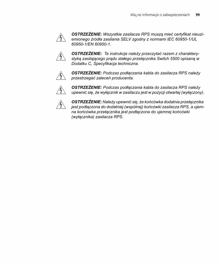
Wa¿ne informacje o zabezpieczeniach 99
DUA1715-0AAA02.book Page 99 Wednesday, March 23, 2005 11:17 AM
OSTRZEŻENIE: Wszystkie zasilacze RPS muszą mieć certyfikat nieuzi-emionego źródła zasilania SELV zgodny z normami IEC 60950-1/UL 60950-1/EN 60950-1.
OSTRZEŻENIE: Te instrukcje należy przeczytać razem z charaktery-styką zasilającego prądu stałego przełącznika Switch 5500 opisaną w Dodatku C, Specyfikacja techniczna.
OSTRZEŻENIE: Podczas podłączania kabla do zasilacza RPS należy przestrzegać zaleceń producenta.
OSTRZEŻENIE: Podczas podłączania kabla do zasilacza RPS należy upewnić się, że wyłącznik w zasilaczu jest w pozycji otwartej (wyłączony).
OSTRZEŻENIE: Należy upewnić się, że końcówka dodatnia przełącznika jest podłączona do dodatniej (wspólnej) końcówki zasilacza RPS, a ujem-na końcówka przełącznika jest podłączona do ujemnej końcówki (wyłącznika) zasilacza RPS.

100 APPENDIX A: SAFETY INFORMATION
DUA1715-0AAA02.book Page 100 Wednesday, March 23, 2005 11:17 AM
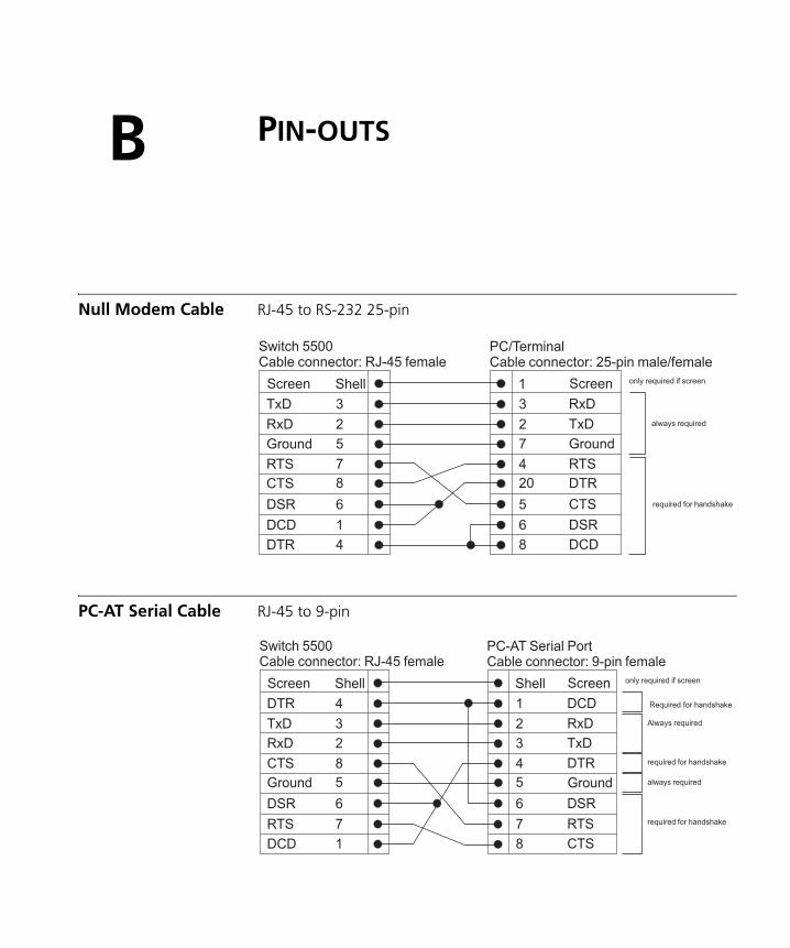
DUA1715-0AAA02.book Page 101 Wednesday, March 23, 2005 11:17 AM
B
PIN-OUTSNull Modem Cable RJ-45 to RS-232 25-pin
PC-AT Serial Cable RJ-45 to 9-pin
Screen
TxD
RxD
Ground
RTS
CTS
DSR
DCD
DTR
Screen
RxD
TxD
Ground
RTS
DTR
CTS
DSR
DCD
Shell
3
2
5
7
8
6
1
4
1
3
2
7
4
20
5
6
8
Switch 5500Cable connector: RJ-45 female
PC/TerminalCable connector: 25-pin male/female
only required if screen
always required
required for handshake
Screen
DTR
TxD
RxD
CTS
Ground
DSR
RTS
DCD
Screen
DCD
RxD
TxD
DTR
Ground
DSR
RTS
CTS
Shell
4
3
2
8
5
6
7
1
Shell
1
2
3
4
5
6
7
8
Switch 5500Cable connector: RJ-45 female
PC-AT Serial PortCable connector: 9-pin female
only required if screen
Always required
always required
required for handshake
required for handshake
Required for handshake
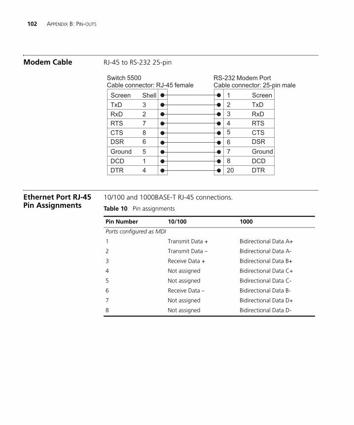
102 APPENDIX B: PIN-OUTS
DUA1715-0AAA02.book Page 102 Wednesday, March 23, 2005 11:17 AM
Modem Cable RJ-45 to RS-232 25-pin
Ethernet Port RJ-45 Pin Assignments
10/100 and 1000BASE-T RJ-45 connections.
Table 10 Pin assignments
Screen
TxD
RxD
RTS
CTS
DSR
Ground
DCD
DTR
Screen
TxD
RxD
RTS
CTS
DSR
Ground
DCD
DTR
Shell
3
2
7
8
6
5
1
4
1
2
3
4
5
6
7
8
20
Switch 5500Cable connector: RJ-45 female
RS-232 Modem PortCable connector: 25-pin male
Pin Number 10/100 1000
Ports configured as MDI
1 Transmit Data + Bidirectional Data A+
2 Transmit Data – Bidirectional Data A-
3 Receive Data + Bidirectional Data B+
4 Not assigned Bidirectional Data C+
5 Not assigned Bidirectional Data C-
6 Receive Data – Bidirectional Data B-
7 Not assigned Bidirectional Data D+
8 Not assigned Bidirectional Data D-
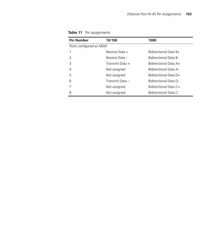
Ethernet Port RJ-45 Pin Assignments 103
DUA1715-0AAA02.book Page 103 Wednesday, March 23, 2005 11:17 AM
Table 11 Pin assignments
Pin Number 10/100 1000
Ports configured as MDIX
1 Receive Data + Bidirectional Data B+
2 Receive Data - Bidirectional Data B-
3 Transmit Data + Bidirectional Data A+
4 Not assigned Bidirectional Data A-
5 Not assigned Bidirectional Data D+
6 Transmit Data – Bidirectional Data D-
7 Not assigned Bidirectional Data C+
8 Not assigned Bidirectional Data C-

104 APPENDIX B: PIN-OUTS
DUA1715-0AAA02.book Page 104 Wednesday, March 23, 2005 11:17 AM
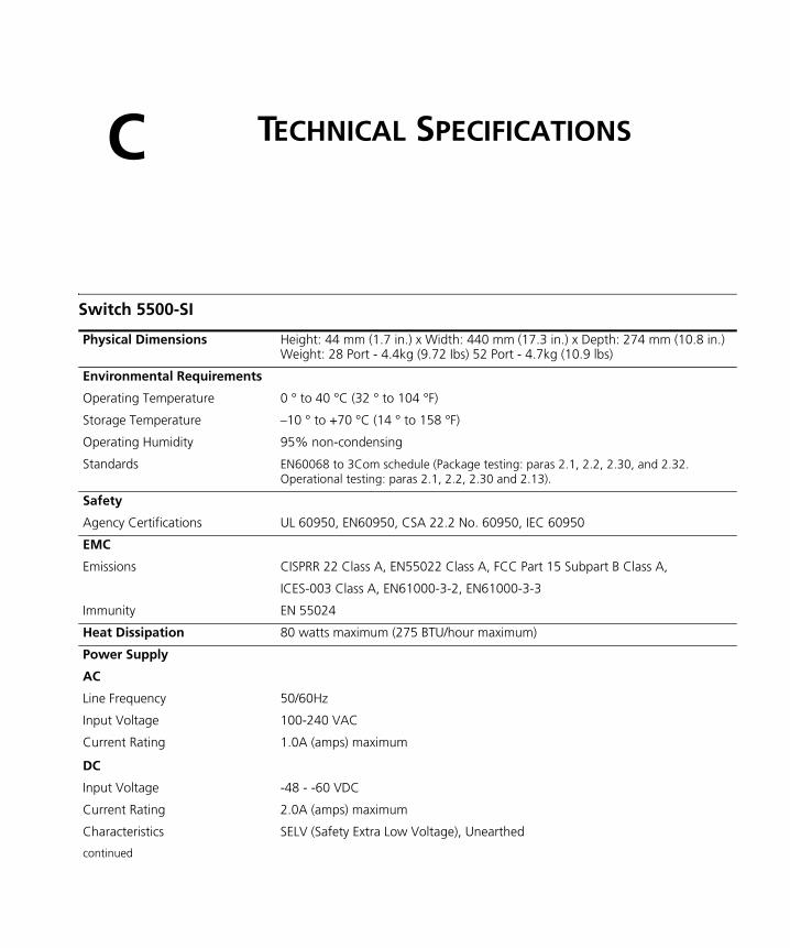
DUA1715-0AAA02.book Page 105 Wednesday, March 23, 2005 11:17 AM
C
TECHNICAL SPECIFICATIONSSwitch 5500-SI
Physical Dimensions Height: 44 mm (1.7 in.) x Width: 440 mm (17.3 in.) x Depth: 274 mm (10.8 in.) Weight: 28 Port - 4.4kg (9.72 Ibs) 52 Port - 4.7kg (10.9 lbs)
Environmental Requirements
Operating Temperature 0 ° to 40 °C (32 ° to 104 °F)
Storage Temperature –10 ° to +70 °C (14 ° to 158 °F)
Operating Humidity 95% non-condensing
Standards EN60068 to 3Com schedule (Package testing: paras 2.1, 2.2, 2.30, and 2.32. Operational testing: paras 2.1, 2.2, 2.30 and 2.13).
Safety
Agency Certifications UL 60950, EN60950, CSA 22.2 No. 60950, IEC 60950
EMC
Emissions CISPRR 22 Class A, EN55022 Class A, FCC Part 15 Subpart B Class A,
ICES-003 Class A, EN61000-3-2, EN61000-3-3
Immunity EN 55024
Heat Dissipation 80 watts maximum (275 BTU/hour maximum)
Power Supply
AC
Line Frequency 50/60Hz
Input Voltage 100-240 VAC
Current Rating 1.0A (amps) maximum
DC
Input Voltage -48 - -60 VDC
Current Rating 2.0A (amps) maximum
Characteristics SELV (Safety Extra Low Voltage), Unearthed
continued
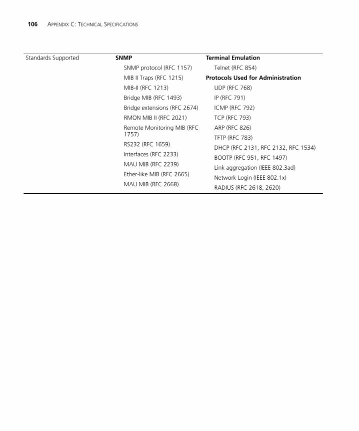
106 APPENDIX C: TECHNICAL SPECIFICATIONS
DUA1715-0AAA02.book Page 106 Wednesday, March 23, 2005 11:17 AM
Standards Supported SNMP
SNMP protocol (RFC 1157)
MIB II Traps (RFC 1215)
MIB-II (RFC 1213)
Bridge MIB (RFC 1493)
Bridge extensions (RFC 2674)
RMON MIB II (RFC 2021)
Remote Monitoring MIB (RFC 1757)
RS232 (RFC 1659)
Interfaces (RFC 2233)
MAU MIB (RFC 2239)
Ether-like MIB (RFC 2665)
MAU MIB (RFC 2668)
Terminal Emulation
Telnet (RFC 854)
Protocols Used for Administration
UDP (RFC 768)
IP (RFC 791)
ICMP (RFC 792)
TCP (RFC 793)
ARP (RFC 826)
TFTP (RFC 783)
DHCP (RFC 2131, RFC 2132, RFC 1534)
BOOTP (RFC 951, RFC 1497)
Link aggregation (IEEE 802.3ad)
Network Login (IEEE 802.1x)
RADIUS (RFC 2618, 2620)
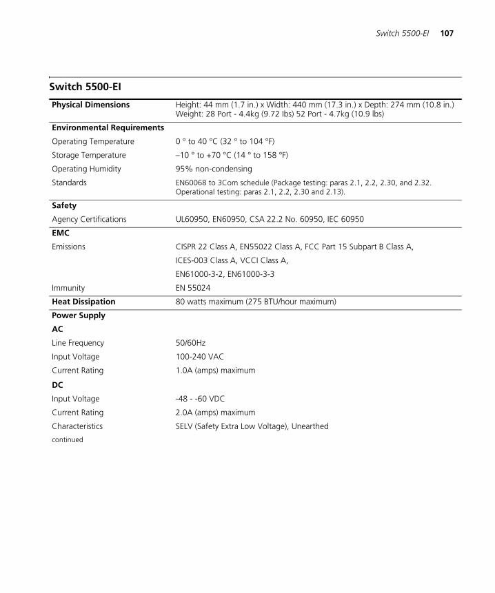
Switch 5500-EI 107
DUA1715-0AAA02.book Page 107 Wednesday, March 23, 2005 11:17 AM
Switch 5500-EI
Physical Dimensions Height: 44 mm (1.7 in.) x Width: 440 mm (17.3 in.) x Depth: 274 mm (10.8 in.) Weight: 28 Port - 4.4kg (9.72 Ibs) 52 Port - 4.7kg (10.9 lbs)
Environmental Requirements
Operating Temperature 0 ° to 40 °C (32 ° to 104 °F)
Storage Temperature –10 ° to +70 °C (14 ° to 158 °F)
Operating Humidity 95% non-condensing
Standards EN60068 to 3Com schedule (Package testing: paras 2.1, 2.2, 2.30, and 2.32. Operational testing: paras 2.1, 2.2, 2.30 and 2.13).
Safety
Agency Certifications UL60950, EN60950, CSA 22.2 No. 60950, IEC 60950
EMC
Emissions CISPR 22 Class A, EN55022 Class A, FCC Part 15 Subpart B Class A,
ICES-003 Class A, VCCI Class A,
EN61000-3-2, EN61000-3-3
Immunity EN 55024
Heat Dissipation 80 watts maximum (275 BTU/hour maximum)
Power Supply
AC
Line Frequency 50/60Hz
Input Voltage 100-240 VAC
Current Rating 1.0A (amps) maximum
DC
Input Voltage -48 - -60 VDC
Current Rating 2.0A (amps) maximum
Characteristics SELV (Safety Extra Low Voltage), Unearthed
continued
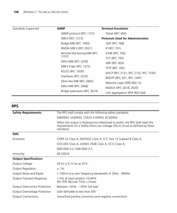
108 APPENDIX C: TECHNICAL SPECIFICATIONS
DUA1715-0AAA02.book Page 108 Wednesday, March 23, 2005 11:17 AM
RPS
Standards Supported SNMP
SNMP protocol (RFC 1157)
MIB-II (RFC 1213)
Bridge MIB (RFC 1493)
RMON MIB II (RFC 2021)
Remote Monitoring MIB (RFC 1757)
MAU MIB (RFC 2239)
MIB II Traps (RFC 1215)
RS232 (RFC 1659)
Interfaces (RFC 2233)
Ether-like MIB (RFC 2665)
MAU MIB (RFC 2668)
Bridge extensions (RFC 2674)
Terminal Emulation
Telnet (RFC 854)
Protocols Used for Administration
UDP (RFC 768)
IP (RFC 791)
ICMP (RFC 792)
TCP (RFC 793)
ARP (RFC 826)
TFTP (RFC 783)
DHCP (RFC 2131, RFC 2132, RFC 1534)
BOOTP (RFC 951, RFC 1497)
Network Login (IEEE 802.1x)
RADIUS (RFC 2618, 2620)
Link aggregation (IEEE 802.3ad)
Safety Requirements The RPS shall comply with the following safety standards:
EN60950, UL60950, CSA22.2 60950, IEC60950
When the output is floating (not referenced to earth), the RPS shall meet the requirements for a Safety Extra Low Voltage (SELV) circuit as defined by these standards
EMC
Emissions CISPR 22 Class A, EN55022 Class A, FCC Part 15 Subpart B Class A,
ICES-003 Class A, AS/NZS 3548 Class A, VCCI Class A,
EN61000-3-2, EN61000-3-3
Immunity EN 55024
Output Specifications
Output Voltage 54.5V + 0.1V dc at 25°C
Output Regulation + 1%
Output Noise and Ripple < 100mV p-p over frequency bandwidth of 30Hz - 30MHz
Output Transient Response < 5% at load variation 10-90%90-10% Recover Time < 2msec
Output Overcurrent Protection Between 105% - 130% full load
Output Overvoltage Protection User definable to less than 59V
Output Connections Unearthed positive (common) and negative connections
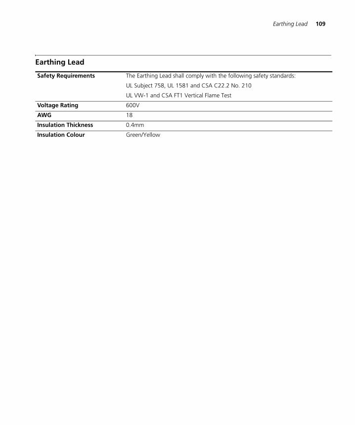
Earthing Lead 109
DUA1715-0AAA02.book Page 109 Wednesday, March 23, 2005 11:17 AM
Earthing Lead
Safety Requirements The Earthing Lead shall comply with the following safety standards:
UL Subject 758, UL 1581 and CSA C22.2 No. 210
UL VW-1 and CSA FT1 Vertical Flame Test
Voltage Rating 600V
AWG 18
Insulation Thickness 0.4mm
Insulation Colour Green/Yellow

110 APPENDIX C: TECHNICAL SPECIFICATIONS
DUA1715-0AAA02.book Page 110 Wednesday, March 23, 2005 11:17 AM
DUA1715-0AAA02.book Page 111 Wednesday, March 23, 2005 11:17 AM
D
OBTAINING SUPPORT FOR YOUR PRODUCTRegister Your Product
Warranty and other service benefits start from the date of purchase, so it is important to register your product quickly to ensure you get full use of the warranty and other service benefits available to you.
Warranty and other service benefits are enabled through product registration. Register your product at http://eSupport.3com.com/. 3Com eSupport services are based on accounts that you create or have authorization to access. First time users must apply for a user name and password that provides access to a number of eSupport features including Product Registration, Repair Services, and Service Request. If you have trouble registering your product, please contact 3Com Global Services for assistance.
Purchase Value-Added Services
To enhance response times or extend warranty benefits, contact 3Com or your authorized 3Com reseller. Value-added services like 3Com ExpressSM and GuardianSM can include 24x7 telephone technical support, software upgrades, onsite assistance or advance hardware replacement. Experienced engineers are available to manage your installation with minimal disruption to your network. Expert assessment and implementation services are offered to fill resource gaps and ensure the success of your networking projects. More information on 3Com maintenance and Professional Services is available at http://www.3com.com/
Contact your authorized 3Com reseller or 3Com for a complete list of the value-added services available in your area.
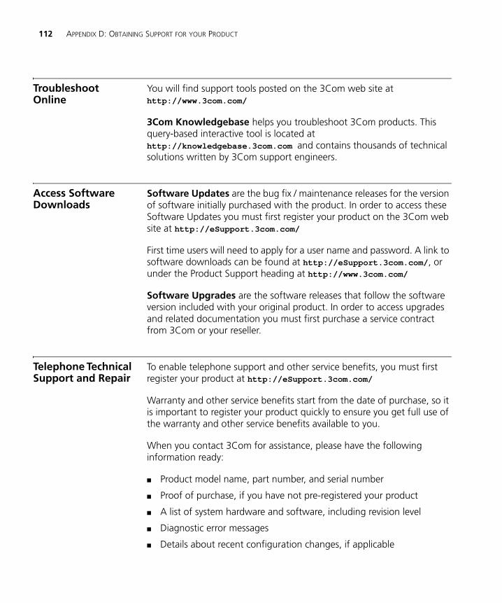
112 APPENDIX D: OBTAINING SUPPORT FOR YOUR PRODUCT
DUA1715-0AAA02.book Page 112 Wednesday, March 23, 2005 11:17 AM
Troubleshoot Online
You will find support tools posted on the 3Com web site at http://www.3com.com/
3Com Knowledgebase helps you troubleshoot 3Com products. This query-based interactive tool is located at http://knowledgebase.3com.com and contains thousands of technical solutions written by 3Com support engineers.
Access Software Downloads
Software Updates are the bug fix / maintenance releases for the version of software initially purchased with the product. In order to access these Software Updates you must first register your product on the 3Com web site at http://eSupport.3com.com/
First time users will need to apply for a user name and password. A link to software downloads can be found at http://eSupport.3com.com/, or under the Product Support heading at http://www.3com.com/
Software Upgrades are the software releases that follow the software version included with your original product. In order to access upgrades and related documentation you must first purchase a service contract from 3Com or your reseller.
Telephone Technical Support and Repair
To enable telephone support and other service benefits, you must first register your product at http://eSupport.3com.com/
Warranty and other service benefits start from the date of purchase, so it is important to register your product quickly to ensure you get full use of the warranty and other service benefits available to you.
When you contact 3Com for assistance, please have the following information ready:
■ Product model name, part number, and serial number
■ Proof of purchase, if you have not pre-registered your product
■ A list of system hardware and software, including revision level
■ Diagnostic error messages
■ Details about recent configuration changes, if applicable
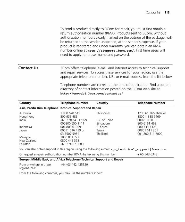
Contact Us 113
DUA1715-0AAA02.book Page 113 Wednesday, March 23, 2005 11:17 AM
To send a product directly to 3Com for repair, you must first obtain a return authorization number (RMA). Products sent to 3Com, without authorization numbers clearly marked on the outside of the package, will be returned to the sender unopened, at the sender’s expense. If your product is registered and under warranty, you can obtain an RMA number online at http://eSupport.3com.com/. First time users will need to apply for a user name and password.
Contact Us 3Com offers telephone, e-mail and internet access to technical support and repair services. To access these services for your region, use the appropriate telephone number, URL or e-mail address from the list below.
Telephone numbers are correct at the time of publication. Find a current directory of contact information posted on the 3Com web site at http://csoweb4.3com.com/contactus/
Country Telephone Number Country Telephone Number
Asia, Pacific Rim Telephone Technical Support and Repair
AustraliaHong KongIndia
IndonesiaJapan
MalaysiaNew ZealandPakistan
1 800 678 515800 933 486+61 2 9424 5179 or000800 650 1111001 803 6100900531 616 439 or03 3507 59841800 801 7770800 446 398+61 2 9937 5083
Philippines
P.R. of ChinaSingaporeS. KoreaTaiwanThailand
1235 61 266 2602 or1800 1 888 9469800 810 3033800 6161 463080 333 330800801 611 261001 800 611 2000
You can also obtain support in this region using the following e-mail: [email protected]
Or request a repair authorization number (RMA) by fax using this number: + 65 543 6348
Europe, Middle East, and Africa Telephone Technical Support and Repair
From anywhere in these regions, call:
+44 (0)1442 435529
From the following countries, you may use the numbers shown:
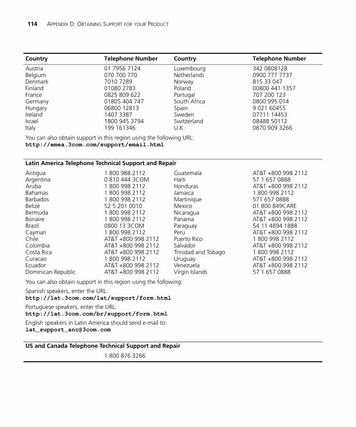
114 APPENDIX D: OBTAINING SUPPORT FOR YOUR PRODUCT
DUA1715-0AAA02.book Page 114 Wednesday, March 23, 2005 11:17 AM
AustriaBelgiumDenmarkFinland FranceGermanyHungaryIrelandIsraelItaly
01 7956 7124070 700 7707010 728901080 27830825 809 62201805 404 74706800 128131407 33871800 945 3794199 161346
LuxembourgNetherlandsNorwayPolandPortugalSouth AfricaSpainSwedenSwitzerlandU.K.
342 08081280900 777 7737815 33 04700800 441 1357707 200 1230800 995 0149 021 6045507711 1445308488 501120870 909 3266
You can also obtain support in this region using the following URL: http://emea.3com.com/support/email.html
Latin America Telephone Technical Support and Repair
AntiguaArgentinaArubaBahamasBarbadosBelizeBermudaBonaireBrazilCaymanChileColombiaCosta RicaCuracaoEcuadorDominican Republic
1 800 988 21120 810 444 3COM1 800 998 21121 800 998 21121 800 998 211252 5 201 00101 800 998 21121 800 998 21120800 13 3COM1 800 998 2112AT&T +800 998 2112AT&T +800 998 2112AT&T +800 998 21121 800 998 2112AT&T +800 998 2112AT&T +800 998 2112
GuatemalaHaitiHondurasJamaicaMartiniqueMexicoNicaraguaPanamaParaguayPeruPuerto RicoSalvadorTrinidad and TobagoUruguayVenezuelaVirgin Islands
AT&T +800 998 211257 1 657 0888AT&T +800 998 21121 800 998 2112571 657 088801 800 849CAREAT&T +800 998 2112AT&T +800 998 211254 11 4894 1888AT&T +800 998 21121 800 998 2112AT&T +800 998 21121 800 998 2112AT&T +800 998 2112AT&T +800 998 211257 1 657 0888
You can also obtain support in this region using the following:
Spanish speakers, enter the URL: http://lat.3com.com/lat/support/form.html
Portuguese speakers, enter the URL: http://lat.3com.com/br/support/form.html
English speakers in Latin America should send e-mail to:[email protected]
US and Canada Telephone Technical Support and Repair
1 800 876 3266
Country Telephone Number Country Telephone Number
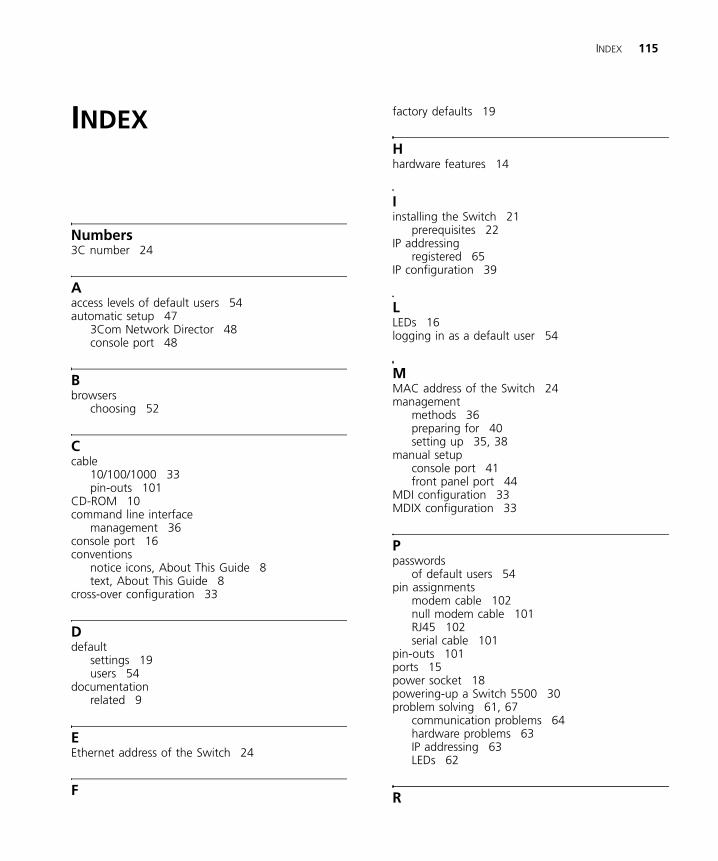
INDEX 115
DUA1715-0AAA02.book Page 115 Wednesday, March 23, 2005 11:17 AM
INDEX
Numbers3C number 24
Aaccess levels of default users 54automatic setup 47
3Com Network Director 48console port 48
Bbrowsers
choosing 52
Ccable
10/100/1000 33pin-outs 101
CD-ROM 10command line interface
management 36console port 16conventions
notice icons, About This Guide 8text, About This Guide 8
cross-over configuration 33
Ddefault
settings 19users 54
documentationrelated 9
EEthernet address of the Switch 24
F
factory defaults 19
Hhardware features 14
Iinstalling the Switch 21
prerequisites 22IP addressing
registered 65IP configuration 39
LLEDs 16logging in as a default user 54
MMAC address of the Switch 24management
methods 36preparing for 40setting up 35, 38
manual setupconsole port 41front panel port 44
MDI configuration 33MDIX configuration 33
Ppasswords
of default users 54pin assignments
modem cable 102null modem cable 101RJ45 102serial cable 101
pin-outs 101ports 15power socket 18powering-up a Switch 5500 30problem solving 61, 67
communication problems 64hardware problems 63IP addressing 63LEDs 62
R
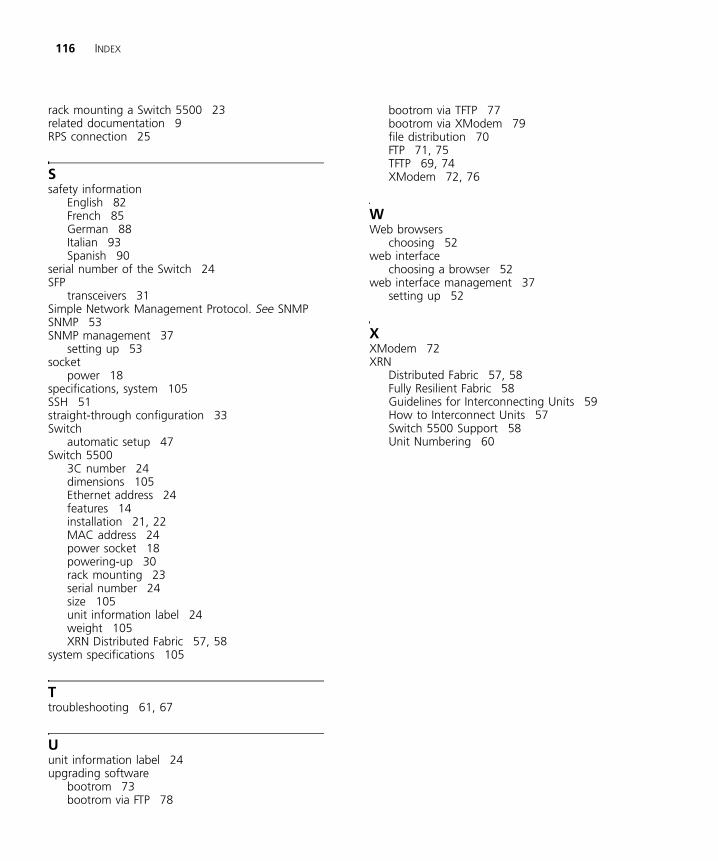
116 INDEX
DUA1715-0AAA02.book Page 116 Wednesday, March 23, 2005 11:17 AM
rack mounting a Switch 5500 23related documentation 9RPS connection 25
Ssafety information
English 82French 85German 88Italian 93Spanish 90
serial number of the Switch 24SFP
transceivers 31Simple Network Management Protocol. See SNMPSNMP 53SNMP management 37
setting up 53socket
power 18specifications, system 105SSH 51straight-through configuration 33Switch
automatic setup 47Switch 5500
3C number 24dimensions 105Ethernet address 24features 14installation 21, 22MAC address 24power socket 18powering-up 30rack mounting 23serial number 24size 105unit information label 24weight 105XRN Distributed Fabric 57, 58
system specifications 105
Ttroubleshooting 61, 67
Uunit information label 24upgrading software
bootrom 73bootrom via FTP 78
bootrom via TFTP 77bootrom via XModem 79file distribution 70FTP 71, 75TFTP 69, 74XModem 72, 76
WWeb browsers
choosing 52web interface
choosing a browser 52web interface management 37
setting up 52
XXModem 72XRN
Distributed Fabric 57, 58Fully Resilient Fabric 58Guidelines for Interconnecting Units 59How to Interconnect Units 57Switch 5500 Support 58Unit Numbering 60
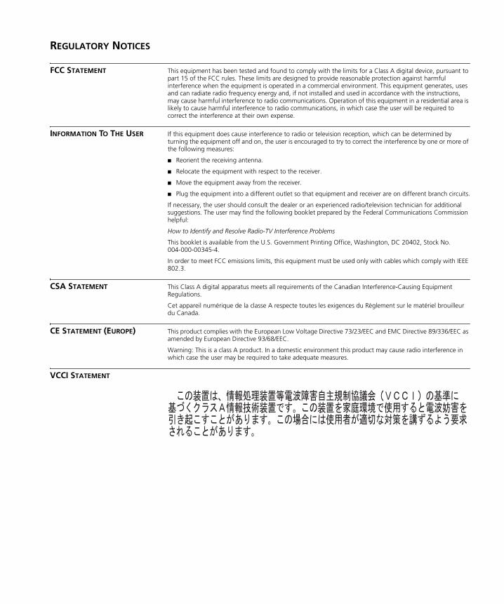
DUA1715-0AAA02.book Page 117 Wednesday, March 23, 2005 11:17 AM
REGULATORY NOTICES
FCC STATEMENT This equipment has been tested and found to comply with the limits for a Class A digital device, pursuant to part 15 of the FCC rules. These limits are designed to provide reasonable protection against harmful interference when the equipment is operated in a commercial environment. This equipment generates, uses and can radiate radio frequency energy and, if not installed and used in accordance with the instructions, may cause harmful interference to radio communications. Operation of this equipment in a residential area is likely to cause harmful interference to radio communications, in which case the user will be required to correct the interference at their own expense.
INFORMATION TO THE USER If this equipment does cause interference to radio or television reception, which can be determined by turning the equipment off and on, the user is encouraged to try to correct the interference by one or more of the following measures:
■ Reorient the receiving antenna.
■ Relocate the equipment with respect to the receiver.
■ Move the equipment away from the receiver.
■ Plug the equipment into a different outlet so that equipment and receiver are on different branch circuits.
If necessary, the user should consult the dealer or an experienced radio/television technician for additional suggestions. The user may find the following booklet prepared by the Federal Communications Commission helpful:
How to Identify and Resolve Radio-TV Interference Problems
This booklet is available from the U.S. Government Printing Office, Washington, DC 20402, Stock No. 004-000-00345-4.
In order to meet FCC emissions limits, this equipment must be used only with cables which comply with IEEE 802.3.
CSA STATEMENT This Class A digital apparatus meets all requirements of the Canadian Interference-Causing Equipment Regulations.
Cet appareil numérique de la classe A respecte toutes les exigences du Règlement sur le matériel brouilleur du Canada.
CE STATEMENT (EUROPE) This product complies with the European Low Voltage Directive 73/23/EEC and EMC Directive 89/336/EEC as amended by European Directive 93/68/EEC.
Warning: This is a class A product. In a domestic environment this product may cause radio interference in which case the user may be required to take adequate measures.
VCCI STATEMENT

DUA1715-0AAA02.book Page 118 Wednesday, March 23, 2005 11:17 AM