Embed Size (px)
Citation preview

SuperStack® 3Switch 4300 Implementation Guide
http://www.3com.com/
Part No. DUA1710-0BAA01Published March 2001
3C17100

3Com Corporation5400 Bayfront Plaza Santa Clara, California 95052-8145
Copyright © 2001, 3Com Technologies. All rights reserved. No part of this documentation may be reproduced in any form or by any means or used to make any derivative work (such as translation, transformation, or adaptation) without written permission from 3Com Technologies.
3Com Technologies reserves the right to revise this documentation and to make changes in content from time to time without obligation on the part of 3Com Technologies to provide notification of such revision or change.
3Com Technologies provides this documentation without warranty, term, or condition of any kind, either implied or expressed, including, but not limited to, the implied warranties, terms or conditions of merchantability, satisfactory quality, and fitness for a particular purpose. 3Com may make improvements or changes in the product(s) and/or the program(s) described in this documentation at any time.
If there is any software on removable media described in this documentation, it is furnished under a license agreement included with the product as a separate document, in the hard copy documentation, or on the removable media in a directory file named LICENSE.TXT or !LICENSE.TXT. If you are unable to locate a copy, please contact 3Com and a copy will be provided to you.
UNITED STATES GOVERNMENT LEGEND
If you are a United States government agency, then this documentation and the software described herein are provided to you subject to the following:
All technical data and computer software are commercial in nature and developed solely at private expense. Software is delivered as “Commercial Computer Software” as defined in DFARS 252.227-7014 (June 1995) or as a “commercial item” as defined in FAR 2.101(a) and as such is provided with only such rights as are provided in 3Com’s standard commercial license for the Software. Technical data is provided with limited rights only as provided in DFAR 252.227-7015 (Nov 1995) or FAR 52.227-14 (June 1987), whichever is applicable. You agree not to remove or deface any portion of any legend provided on any licensed program or documentation contained in, or delivered to you in conjunction with, this User Guide.
Unless otherwise indicated, 3Com registered trademarks are registered in the United States and may or may not be registered in other countries.
3Com, SuperStack, and Transcend are registered trademarks of 3Com Corporation. The 3Com logo is a trademark of 3Com Corporation.
Intel and Pentium are registered trademarks of Intel Corporation. Microsoft, MS-DOS, Windows, and Windows NT are registered trademarks of Microsoft Corporation. Novell and NetWare are registered trademarks of Novell, Inc. UNIX is a registered trademark in the United States and other countries, licensed exclusively through X/Open Company, Ltd.
All other company and product names may be trademarks of the respective companies with which they are associated.
ENVIRONMENTAL STATEMENT
It is the policy of 3Com Corporation to be environmentally-friendly in all operations. To uphold our policy, we are committed to:
Establishing environmental performance standards that comply with national legislation and regulations.
Conserving energy, materials and natural resources in all operations.
Reducing the waste generated by all operations. Ensuring that all waste conforms to recognized environmental standards. Maximizing the recyclable and reusable content of all products.
Ensuring that all products can be recycled, reused and disposed of safely.
Ensuring that all products are labelled according to recognized environmental standards.
Improving our environmental record on a continual basis.
End of Life Statement
3Com processes allow for the recovery, reclamation and safe disposal of all end-of-life electronic components.
Regulated Materials Statement
3Com products do not contain any hazardous or ozone-depleting material.
Environmental Statement about the Documentation
The documentation for this product is printed on paper that comes from sustainable, managed forests; it is fully biodegradable and recyclable, and is completely chlorine-free. The varnish is environmentally-friendly, and the inks are vegetable-based with a low heavy-metal content.

CONTENTS
ABOUT THIS GUIDE
Conventions 8Related Documentation 9
Accessing Online Documentation 9Documentation Comments 10Product Registration 10
1 SWITCH FEATURES OVERVIEW
What is Management Software? 13Switch Features Explained 13
BOOTP 13Port Security 14Aggregated Links 14Auto-negotiation 14Multicast Filtering 15Spanning Tree Protocol 15Switch Database 15Traffic Prioritization 16Roving Analysis 16RMON 16Broadcast Storm Control 17VLANs 17
2 OPTIMIZING BANDWIDTH
Port Features 19Duplex 19Flow Control 20Auto-negotiation 20
Aggregated Links 20Aggregated Links and Your Switch 4300 21Aggregated Link Example 24

3 USING MULTICAST FILTERING
What is a Multicast? 25Multicast Filtering 25IGMP Multicast Filtering 26
4 USING RESILIENCE FEATURES
Spanning Tree Protocol (STP) 29What is STP? 29How STP Works 31
STP Requirements 31STP Calculation 32STP Configuration 32STP Reconfiguration 33STP Example 33STP Configurations 34
Using STP on a Network with Multiple VLANs 36
5 USING THE SWITCH DATABASE
What is the Switch Database? 37How Switch Database Entries Get Added 37Switch Database Entry States 38
6 USING TRAFFIC PRIORITIZATION
What is Traffic Prioritization? 39How Traffic Prioritization Works 40Traffic Prioritization and Your Switch 41
7 STATUS MONITORING AND STATISTICS
Roving Analysis Port (RAP) 43Roving Analysis and the Switch 4300 43
RMON 44What is RMON? 44
The RMON Groups 44Benefits of RMON 46RMON and the Switch 4300 47

Alarm Events 47The Default Alarm Settings 48
8 SETTING UP VIRTUAL LANS
What are VLANs? 49Benefits of VLANs 50VLANs and Your Switch 51
The Default VLAN 51Creating New VLANs 51Untagged and Tagged VLANs 52Placing a Port in a Single VLAN 52Connecting VLANs to Other VLANs 52
VLAN Configuration Examples 54Using Untagged Connections 54Using 802.1Q Tagged Connections 55
A CONFIGURATION RULES
Configuration Rules for Gigabit Ethernet 59Configuration Rules for Fast Ethernet 60
Configuration Rules with Full Duplex 61
B NETWORK CONFIGURATION EXAMPLES
Network Configuration Examples 64Segmentation Switch Example 64Collapsed Backbone Switch Example 65Desktop Switch Example 66
GLOSSARY
INDEX


ABOUT THIS GUIDE
This guide describes the features of the SuperStack® 3 Switch 4300 and outlines how to use these features to optimize the performance of your network.
This guide is intended for the system or network administrator who is responsible for configuring, using, and managing the Switches. It assumes a working knowledge of local area network (LAN) operations and familiarity with communication protocols that are used to interconnect LANs.
For detailed descriptions of the web interface operations and the command line interface (CLI) commands that you require to manage the Switch please refer to the Management Interface Reference Guide supplied in HTML format on the CD-ROM that accompanies your Switch.
If release notes are shipped with your product and the information there differs from the information in this guide, follow the instructions in the release notes.
Most user guides and release notes are available in Adobe Acrobat Reader Portable Document Format (PDF) or HTML on the 3Com World Wide Web site:
http://www.3com.com/
8 ABOUT THIS GUIDE
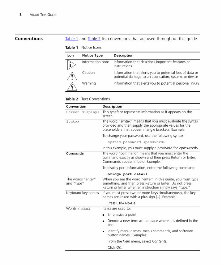
Conventions Table 1 and Table 2 list conventions that are used throughout this guide.
Table 1 Notice Icons
Icon Notice Type Description
Information note Information that describes important features or instructions
Caution Information that alerts you to potential loss of data or potential damage to an application, system, or device
Warning Information that alerts you to potential personal injury
Table 2 Text Conventions
Convention Description
Screen displays This typeface represents information as it appears on the screen.
Syntax The word “syntax” means that you must evaluate the syntax provided and then supply the appropriate values for the placeholders that appear in angle brackets. Example:
To change your password, use the following syntax:
system password <password>
In this example, you must supply a password for <password>.
Commands The word “command” means that you must enter the command exactly as shown and then press Return or Enter. Commands appear in bold. Example:
To display port information, enter the following command:
bridge port detail
The words “enter” and “type”
When you see the word “enter” in this guide, you must type something, and then press Return or Enter. Do not press Return or Enter when an instruction simply says “type.”
Keyboard key names If you must press two or more keys simultaneously, the key names are linked with a plus sign (+). Example:
Press Ctrl+Alt+Del
Words in italics Italics are used to:
■ Emphasize a point.
■ Denote a new term at the place where it is defined in the text.
■ Identify menu names, menu commands, and software button names. Examples:
From the Help menu, select Contents.
Click OK.

Related Documentation 9
Related Documentation
In addition to this guide, each Switch documentation set includes the following:
■ Getting Started Guide
This guide contains:
■ a list of the features supported by the Switch
■ all the information you need to install and set up the Switch in its default state
■ information on how to access the management software to begin managing the Switch.
■ Management Interface Reference Guide
This guide contains information about the web interface operations and CLI (command line interface) commands that enable you to manage the Switch. It contains an explanation for each command and the different parameters available. It is supplied in HTML format on the CD-ROM that accompanies your Switch.
■ Management Quick Reference Guide
This guide contains a summary of the web interface operations and CLI commands that enable you to manage the Switch.
■ Release Notes
These notes provide information about the current software release, including new features, modifications, and known problems.
In addition, there are other publications you may find useful:
■ Documentation accompanying the Expansion Modules.
■ Documentation accompanying the Advanced Redundant Power System.
Accessing OnlineDocumentation
The CD-ROM supplied with your Switch contains the following online documentation:
■ Implementation Guide (PDF format)
■ Management Interface Reference Guide (HTML format)
1 To access the documentation insert the CD-ROM into your CD-ROM drive. If your PC has auto-run enabled, a splash screen will be displayed automatically.

10 ABOUT THIS GUIDE
2 Select the Documentation section from the contents page.
If the online documentation is to be accessed from a local drive or server, you will need to access the CD-ROM contents via the root directory and copy the files from the CD-ROM to a suitable directory.
■ The HTML Reference Guide is stored in the Docs/reference directory on the CD-ROM. The documentation is accessed using the contents.htm file.
■ The PDF Implementation Guide is stored in the Docs/implementation directory of the CD-ROM.
3Com recommends that you copy the Docs/reference directory as a whole to maintain the structure of the files.
Documentation Comments
Your suggestions are very important to us. They will help make our documentation more useful to you. Please e-mail comments about this document to 3Com at:
Please include the following information when contacting us:
■ Document title
■ Document part number (on the title page)
■ Page number (if appropriate)
Example:
■ SuperStack 3 Switch Implementation Guide
■ Part number: DUA1710-0BAA01
■ Page 25
Please note that we can only respond to comments and questions about 3Com product documentation at this e-mail address. Questions related to technical support or sales should be directed in the first instance to your network supplier.
Product Registration
You can now register your SuperStack 3 Switch on the 3Com web site:
http://support.3com.com/registration/frontpg.pl

I
SWITCH FEATURESChapter 1 Switch Features Overview
Chapter 2 Optimizing Bandwidth
Chapter 3 Using Multicast Filtering
Chapter 4 Using Resilience Features
Chapter 5 Using the Switch Database
Chapter 6 Using Traffic Prioritization
Chapter 7 Status Monitoring and Statistics
Chapter 8 Setting Up Virtual LANs

12

1
SWITCH FEATURES OVERVIEWThis chapter contains introductory information about the SuperStack® 3 Switch 4300 management software and supported features. It covers the following topics:
■ What is Management Software?
■ Switch Features Explained
What is Management Software?
Your Switch can operate in its default state. However, to make full use of the features offered by the Switch, and to change and monitor the way it works, you have to access the management software that resides on the Switch. This is known as managing the Switch.
Managing the Switch can help you to improve its efficiency and therefore the overall performance of your network.
There are several different methods of accessing the management software to manage the Switch. These methods are explained in Chapter 3 of the Getting Started Guide that accompanies your Switch.
Switch Features Explained
The management software provides you with the capability to change the default state of some of the Switch features. This section provides a brief overview of these features — their applications are explained in more detail later in this guide.
For a list of the features supported by your Switch, please refer to Chapter 1 of the Getting Started Guide that accompanies your Switch.
BOOTP If you have a BOOTP server on your network you can input the Switch MAC address on the BOOTP server so it will automatically identify the unit and allocate IP information.
14 CHAPTER 1: SWITCH FEATURES OVERVIEW
Port Security Port security guards against unauthorized users connecting devices to your network. The port security feature allows any packets with addresses learned against a port to be forwarded — all other packets are dropped.
Aggregated Links Aggregated links are connections that allow devices to communicate using up to four links in parallel. Aggregated links provide two benefits:
■ They can potentially double, triple or quadruple the bandwidth of a connection.
■ They can provide redundancy — if one link is broken, the other links share the traffic for that link.
For more information about aggregated links, see Chapter 2 “Optimizing Bandwidth”.
Auto-negotiation Auto-negotiation allows ports to auto-negotiate port speed, duplex-mode (only at 10 Mbps and 100 Mbps) and flow control. When auto-negotiation is enabled (default), a port “advertises” its maximum capabilities — these capabilities are the parameters that are supported by the port.
1000BASE-SX/LX and 100BASE-FX ports do not support auto-negotiation of port speed.
1000BASE-T ports support auto-negotiation of port speed and flow control.
Ports operating at 1000 Mbps support full duplex mode only.
For details of the auto-negotation features supported by your Switch, please refer to the Getting Started Guide that accompanies your Switch.
Duplex
Full duplex mode allows packets to be transmitted and received simultaneously and, in effect, doubles the potential throughput of a link.
Flow Control
All Switch ports support flow control, which is a mechanism that prevents packet loss during periods of congestion on the network.

Switch Features Explained 15
Flow control is implemented using the IEEE 802.3x standard for ports operating in full duplex mode, and Intelligent Flow Management (IFM) for ports operating in half duplex mode.
Multicast Filtering Multicast filtering allows the Switch to forward multicast traffic to only the endstations that are part of a predefined multicast group, rather than broadcasting the traffic to the whole network.
The multicast filtering system supported by your Switch uses IGMP (Internet Group Management Protocol) snooping to detect the endstations in each multicast group to which multicast traffic should be forwarded.
For more information about multicast filtering, see Chapter 3 “Using Multicast Filtering”.
Spanning TreeProtocol
Spanning Tree Protocol (STP) is a bridge-based system that makes your network more resilient to link failure and also provides protection from network loops — one of the major causes of broadcast storms.
STP allows you to implement alternative paths for network traffic in the event of path failure and uses a loop-detection process to:
■ Discover the efficiency of each path.
■ Enable the most efficient path.
■ Disable the less efficient paths.
■ Enable one of the less efficient paths if the most efficient path fails.
For more information about STP, see Chapter 4 “Using Resilience Features”.
Switch Database The Switch Database is an integral part of the Switch and is used by the Switch to determine if a packet should be forwarded, and which port should transmit the packet if it is to be forwarded.
For more information about the Switch Database, see Chapter 5 “Using the Switch Database”.

16 CHAPTER 1: SWITCH FEATURES OVERVIEW
Traffic Prioritization Traffic prioritization allows time-sensitive and system-critical data, such as digital video and network-control signals, to be transferred smoothly and with minimal delay over a network. This data is assigned a high priority by the transmitting endstation and traffic prioritization allows high priority data to be forwarded through the Switch without being obstructed by lower priority data.
The system works by using the multiple traffic queues that are present in the hardware of the Switch — high priority data is forwarded on a different queue from lower priority data, and is given preference over the lower priority data.
This system is compatible with the relevant sections of the IEEE 802.1D/D17 standard (incorporating IEEE 802.1p).
For more information about 802.1D and traffic prioritization, see Chapter 6 “Using Traffic Prioritization”.
Roving Analysis Roving analysis is a system that allows you to attach a network analyzer to one port and use it to monitor the traffic of other ports on the Switch. The system works by enabling you to define an analysis port (the port that is connected to the analyzer), and a monitor port (the port that is to be monitored). Once the pair are defined, and you start monitoring, the Switch takes all the traffic going in and out of the monitor port and copies it to the analysis port.
You can use roving analysis when you need the functions of a network analyzer, but do not want to change the physical characteristics of the monitored segment by attaching an analyzer to that segment.
For more information about roving analysis, see Chapter 7 “Status Monitoring and Statistics”.
RMON Remote Monitoring (RMON) is a system that allows you to monitor LANs remotely. The Switch contains RMON probe software that continually collects statistics about the LAN segments connected to the Switch. If you have a management workstation with an RMON management application, the Switch can transfer these statistics to your workstation on request or when a pre-defined threshold is exceeded.
For more information about RMON, see Chapter 7 “Status Monitoring and Statistics”.

Switch Features Explained 17
Broadcast StormControl
Broadcast Storm Control is a system that monitors the level of broadcast traffic on that port. If the broadcast traffic level rises to a pre-defined number of frames per second (threshold), the broadcast traffic on the port is blocked until the broadcast traffic level drops below the threshold. This system prevents the overwhelming broadcast traffic that can result from network equipment which is faulty or configured incorrectly.
VLANs A Virtual LAN (VLAN) is a flexible group of devices that can be located anywhere in a network, but which communicate as if they are on the same physical segment. With VLANs, you can segment your network without being restricted by physical connections — a limitation of traditional network design. As an example, with VLANs you can segment your network according to:
■ Departmental groups
■ Hierarchical groups
■ Usage groups
For more information about VLANs, see Chapter 8 “Setting Up Virtual LANs”.

18 CHAPTER 1: SWITCH FEATURES OVERVIEW

2
OPTIMIZING BANDWIDTHThere are many ways you can optimize the bandwidth on your network and improve network performance. If you utilize certain Switch features you can provide the following benefits to your network and end users:
■ Increased bandwidth
■ Quicker connections
■ Faster transfer of data
■ Minimized data errors
■ Reduced network downtime
Port Features The default state for all the features detailed below provides the best configuration for a typical user. In normal operation, you do not need to alter the Switch from its default state. However, under certain conditions you may wish to alter the default state of these ports, for example, if you are connecting to old equipment that does not comply with the IEEE 802.3x standard.
Duplex Full duplex allows packets to be transmitted and received simultaneously and, in effect, doubles the potential throughput of a link. Half duplex only allows packets to be transmitted or received at any one time.
To communicate effectively, both devices at either end of a link must use the same duplex mode. If the devices at either end of a link support auto-negotiation, this is done automatically. If the devices at either end of a link do not support auto-negotiation, both ends must be manually set to full duplex or half duplex accordingly.
Ports operating at 1000 Mbps support full duplex mode only.

20 CHAPTER 2: OPTIMIZING BANDWIDTH
Flow Control All Switch ports support flow control, which is a mechanism that prevents packet loss during periods of congestion on the network. Packet loss is caused by one or more devices sending traffic to an already overloaded port on the Switch. Flow control prevents packet loss by inhibiting the transmitting port from generating more packets until the period of congestion ends.
Flow control is implemented using the IEEE 802.3x standard for ports operating in full duplex mode, and Intelligent Flow Management (IFM) for ports operating in half duplex mode.
Auto-negotiation Auto-negotiation allows ports to auto-negotiate port speed, duplex-mode (only at 10 Mbps and 100 Mbps) and flow control. When auto-negotiation is enabled (default), a port “advertises” its maximum capabilities — these capabilities are the parameters that are supported by the port.
You can disable auto-negotiation for the whole Switch, or per port.
1000BASE-SX/LX and 100BASE-FX ports do not support auto-negotiation of port speed.
1000BASE-T ports support auto-negotiation of port speed and flow control.
Ports operating at 1000 Mbps support full duplex mode only.
Conditions that affect auto-negotiation:
■ Ports at both ends of the link must be set to auto-negotiate.
■ 1000BASE-SX/LX ports support auto-negotiation, however, the standard defines that 1000BASE-SX/LX can only operate at 1000 Mbps, full duplex mode, so they can only auto-negotiate flow control.
Aggregated Links Aggregated links are connections that allow devices to communicate using up to four links in parallel. These parallel links provide two benefits:
■ They can potentially double, triple or quadruple the bandwidth of a connection.
Aggregated Links 21
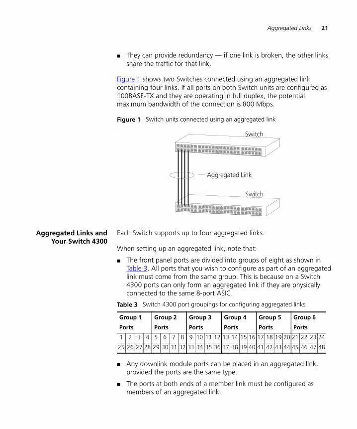
■ They can provide redundancy — if one link is broken, the other links share the traffic for that link.
Figure 1 shows two Switches connected using an aggregated link containing four links. If all ports on both Switch units are configured as 100BASE-TX and they are operating in full duplex, the potential maximum bandwidth of the connection is 800 Mbps.
Figure 1 Switch units connected using an aggregated link.
Aggregated Links andYour Switch 4300
Each Switch supports up to four aggregated links.
When setting up an aggregated link, note that:
■ The front panel ports are divided into groups of eight as shown in Table 3. All ports that you wish to configure as part of an aggregated link must come from the same group. This is because on a Switch 4300 ports can only form an aggregated link if they are physically connected to the same 8-port ASIC.
Table 3 Switch 4300 port groupings for configuring aggregated links
■ Any downlink module ports can be placed in an aggregated link, provided the ports are the same type.
■ The ports at both ends of a member link must be configured as members of an aggregated link.
Group 1
Ports
Group 2
Ports
Group 3
Ports
Group 4
Ports
Group 5
Ports
Group 6
Ports
1 2 3 4 5 6 7 8 9 10 11 12 13 14 15 16 17 18 19 20 21 22 23 24
25 26 27 28 29 30 31 32 33 34 35 36 37 38 39 40 41 42 43 44 45 46 47 48

22 CHAPTER 2: OPTIMIZING BANDWIDTH
■ Member links must retain the same groupings at both ends of an aggregated link. For example, the configuration in Figure 2 will not work as Switch A has one aggregated link defined whose member links are then split between two aggregated links defined on Switches B and C. To make this configuration work you need to have two aggregated links defined on Switch A, one containing the member links for Switch B and the other containing those for Switch C.
Figure 2 An illegal aggregated link configuration
■ A member link port can only belong to one aggregated link.
■ The member link ports must be fiber or twisted pair ports.
■ The member link ports must operate in full duplex mode.
■ All member link ports will be active within the aggregated link regardless of speed or duplex mode.
■ The aggregated link does not support security or roving analysis.
■ The ports at either end of a member link must have an identical configuration. And ideally all member links within an aggregated link should also have an identical configuration.
When using an aggregated link, note that:
■ To gather statistics about an aggregated link, you must add together the statistics for each port in the aggregated link.
■ If you wish to disable a single member link of an aggregated link, you must first physically remove the connection to ensure that you do not lose any traffic, before you disable both ends of the member link separately. If you do this, the traffic destined for that link is distributed to the other links in the aggregated link.

Aggregated Links 23
If you do not remove the connection and only disable one end of the member link port, traffic is still forwarded to that port by the aggregated link port at the other end. This means that a significant amount of traffic may be lost.
■ Before removing all member links from an aggregated link, you must disable all the aggregated link member ports or disconnect all the links, except one — if you do not, a loop may be created.
Traffic Distribution and Link Failure on Aggregated Links
To maximize throughput, all traffic is distributed across the individual member links that make up an aggregated link. Therefore, when a packet is made available for transmission down an aggregated link, a hardware-based traffic-distribution algorithm determines which particular port in the aggregated link should be used.
The algorithm distributes the traffic among the member links as efficiently as possible. To avoid the potential problem of out-of-sequence packets (or “packet re-ordering”), the algorithm ensures that all the conversations between a given pair of endstations will pass through the same port in the aggregated link. Single-to-multiple-endstation conversations, on the other hand, may still take place over different ports.
On the Switch 4300, traffic distribution is carried out on learned address packets only. Therefore a packet with an unknown desination address will always be sent down the primary link (a designated port determined by the software). Once a reply packet has returned and the address learned, all future packets will be sent down a single link.
On a Switch 4300 aggregated link, addresses are learned against the member link ports, not against the aggregated link itself.
If the link state on any of the ports in an aggregated link becomes inactive due to link failure, then the Switch will automatically redirect the aggregated link traffic to the remaining ports. Aggregated links therefore provide built-in resilience for your network.
The Switch also incorporates a mechanism to prevent the possible occurrence of packet re-ordering when a link recovers too soon after a failure.
24 CHAPTER 2: OPTIMIZING BANDWIDTH
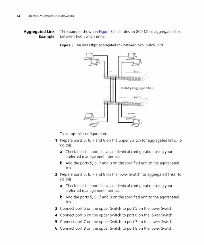
Aggregated LinkExample
The example shown in Figure 3 illustrates an 800 Mbps aggregated link between two Switch units.
Figure 3 An 800 Mbps aggregated link between two Switch units
To set up this configuration:
1 Prepare ports 5, 6, 7 and 8 on the upper Switch for aggregated links. To do this:
a Check that the ports have an identical configuration using your preferred management interface.
b Add the ports 5, 6, 7 and 8 on the specified unit to the aggregated link.
2 Prepare ports 5, 6, 7 and 8 on the lower Switch for aggregated links. To do this:
a Check that the ports have an identical configuration using your preferred management interface.
b Add the ports 5, 6, 7 and 8 on the specified unit to the aggregated link.
3 Connect port 5 on the upper Switch to port 5 on the lower Switch.
4 Connect port 6 on the upper Switch to port 6 on the lower Switch.
5 Connect port 7 on the upper Switch to port 7 on the lower Switch.
6 Connect port 8 on the upper Switch to port 8 on the lower Switch.

3
USING MULTICAST FILTERINGMulticast filtering improves the performance of networks that carry multicast traffic.
This chapter explains multicasts, multicast filtering, and how multicast filtering can be implemented on your Switch. It covers the following topics:
■ What is a Multicast?
■ Multicast Filtering
■ IGMP Multicast Filtering
What is a Multicast?
A multicast is a packet that is intended to go to a subset of endstations in a LAN, or VLAN, that belong to a multicast group. If the network is set up correctly, a multicast can only be sent to an endstation if it has joined the relevant group.
A typical use of multicasts is in video-conferencing, where high volumes of traffic need to be sent to several endstations simultaneously, but where broadcasting that traffic to all endstations would seriously reduce network performance.
Multicast Filtering Multicast filtering is the system by which endstations only receive multicast traffic if they register to join specific multicast groups. With multicast filtering, network devices only forward multicast traffic to the ports that are connected to registered endstations.

26 CHAPTER 3: USING MULTICAST FILTERING
Figure 4 The effect of multicast filtering
Your Switch provides automatic filtering support using IGMP (Internet Group Management Protocol) Snooping. It “snoops” on exchanges between endstations and an IGMP device, typically a router, to detect the ports wishing to join a multicast group.
IGMP Multicast Filtering
IGMP is the system that all multicast-supporting network devices use to register endstations with multicast groups. It can be used on all LANs and VLANs that contain a multicast capable multicast router and on other network devices which support multicast filtering.
IGMP multicast filtering works as follows:
1 The router (or querier) periodically sends query packets to all the endstations in the LANs or VLANs that are connected to it.
If your network has more than one router, then the one with the lowest MAC address becomes the querier.
2 When an endstation receives a query packet, it sends a report packet back that identifies the multicast group that the endstation would like to join.

IGMP Multicast Filtering 27
3 When the report packet arrives at a port on a Switch with IGMP multicast learning enabled, the Switch learns that the port is to forward traffic for the multicast group and then forwards the packet to the router.
4 When the router receives the report packet, it registers that the LAN or VLAN requires traffic for the multicast groups.
5 When the router forwards traffic for the multicast group to the LAN or VLAN, the Switch units only forward the traffic to ports that received a report packet.
If multicast filtering is enabled, the Switch will always filter unknown multicast streams, independent of a querier being present in the network.
Enabling IGMP Multicast Learning
You can enable or disable multicast learning and IGMP querying using the snoopMode command on the CLI or the web interface. For more information about enabling IGMP multicast learning, please refer to the Management Interface Reference Guide supplied on your Switch CD-ROM.
If IGMP multicast learning is disabled then multicast traffic is always forwarded, that is, it floods the network.
For information about configuring IGMP functionality on an endstation, refer to the user documentation supplied with your endstation or the endstation’s Network Interface Card (NIC).

28 CHAPTER 3: USING MULTICAST FILTERING

4
USING RESILIENCE FEATURESSetting up resilience on your network helps protect critical links against failure, protects against network loops, and reduces network downtime to a minimum.
The main feature supported by the Switch that provides resilience for your network is Spanning Tree Protocol (STP).
The Switch also supports aggregated links which increase bandwidth and also provide resilience. Aggregated links will operate with STP enabled. For more information, see Aggregated Links on page 20.
Spanning Tree Protocol (STP)
The Spanning Tree Protocol (STP) makes your network more resilient to link failure and also provides a protection from loops — one of the major causes of broadcast storms.
The following sections explain more about STP and the protocol features supported by your Switch. They cover the following topics:
■ What is STP?
■ How STP Works
■ Using STP on a Network with Multiple VLANs
The protocol is a part of the IEEE 802.1D bridge specification. To explain STP more effectively, your Switch will be referred to as a bridge.
What is STP? STP is a bridge-based system that allows you to implement parallel paths for network traffic and uses a loop-detection process to:
■ Find and disable the less efficient paths (that is, the paths that have a lower bandwidth).
■ Enable one of the less efficient paths if the most efficient path fails.

30 CHAPTER 4: USING RESILIENCE FEATURES
As an example, Figure 5 shows a network containing three LAN segments separated by three bridges. With this configuration, each segment can communicate with the others using two paths. Without STP enabled, this configuration creates loops that cause the network to overload.
Figure 5 A network configuration that creates loops
Figure 6 shows the result of enabling STP on the bridges in the configuration. STP detects the duplicate paths and prevents, or blocks, one of them from forwarding traffic, so this configuration will work satisfactorily. STP has determined that traffic from LAN segment 2 to LAN segment 1 can only flow through Bridges C and A, because, for example, this path has a greater bandwidth and is therefore more efficient.
Figure 6 Traffic flowing through Bridges C and A

How STP Works 31
If a link failure is detected, as shown in Figure 7, the STP process reconfigures the network so that traffic from LAN segment 2 flows through Bridge B.
Figure 7 Traffic flowing through Bridge B
STP determines which is the most efficient path between each bridged segment and a specifically assigned reference point on the network. Once the most efficient path has been determined, all other paths are blocked. Therefore, in Figure 5, Figure 6, and Figure 7, STP initially determined that the path through Bridge C was the most efficient, and so blocked the path through Bridge B. After the failure of Bridge C, STP re-evaluated the situation and opened the path through Bridge B.
How STP Works When enabled, STP determines the most appropriate path for traffic through a network. It does this as outlined in the sections below.
STP Requirements Before it can configure the network, the STP system requires:
■ Communication between all the bridges. This communication is carried out using Bridge Protocol Data Units (BPDUs), which are transmitted in packets with a known multicast address.
■ Each bridge to have a Bridge Identifier. This specifies which bridge acts as the central reference point, or Root Bridge, for the STP system — the lower the Bridge Identifier, the more likely the bridge is to become the Root Bridge. The Bridge Identifier is calculated using the MAC address of the bridge and a priority defined for the bridge. The default priority of your Switch is 32768.

32 CHAPTER 4: USING RESILIENCE FEATURES
■ Each port to have a cost. This specifies the efficiency of each link, usually determined by the bandwidth of the link — the higher the cost, the less efficient the link. Table 4 shows the default port costs for a Switch.
Table 4 Default port costs
STP Calculation The first stage in the STP process is the calculation stage. During this stage, each bridge on the network transmits BPDUs that allow the system to work out:
■ The identity of the bridge that is to be the Root Bridge. The Root Bridge is the central reference point from which the network is configured.
■ The Root Path Costs for each bridge — that is, the cost of the paths from each bridge to the Root Bridge.
■ The identity of the port on each bridge that is to be the Root Port. The Root Port is the one that is connected to the Root Bridge using the most efficient path, that is, the one that has the lowest Root Path Cost. Note that the Root Bridge does not have a Root Port.
■ The identity of the bridge that is to be the Designated Bridge of each LAN segment. The Designated Bridge is the one that has the lowest Root Path Cost from that segment. Note that if several bridges have the same Root Path Cost, the one with the lowest Bridge Identifier becomes the Designated Bridge.
All traffic destined to pass in the direction of the Root Bridge flows through the Designated Bridge. The port on this bridge that connects to the segment is called the Designated Bridge Port.
STP Configuration After all the bridges on the network have agreed on the identity of the Root Bridge, and have established the other relevant parameters, each bridge is configured to forward traffic only between its Root Port and the Designated Bridge Ports for the respective network segments. All other ports are blocked, which means that they are prevented from receiving or forwarding traffic.
Port Type Cost
10 Mbps 100
100 Mbps 19
1000 Mbps 4
How STP Works 33
STP Reconfiguration Once the network topology is stable, all the bridges listen for Hello BPDUs transmitted from the Root Bridge at regular intervals. If a bridge does not receive a Hello BPDU after a certain interval (the Max Age time), the bridge assumes that the Root Bridge, or a link between itself and the Root Bridge, has gone down. The bridge then reconfigures the network to cater for the change. If you have configured an SNMP trap destination, when the topology of your network changes, the first bridge to detect the change sends out an SNMP trap.
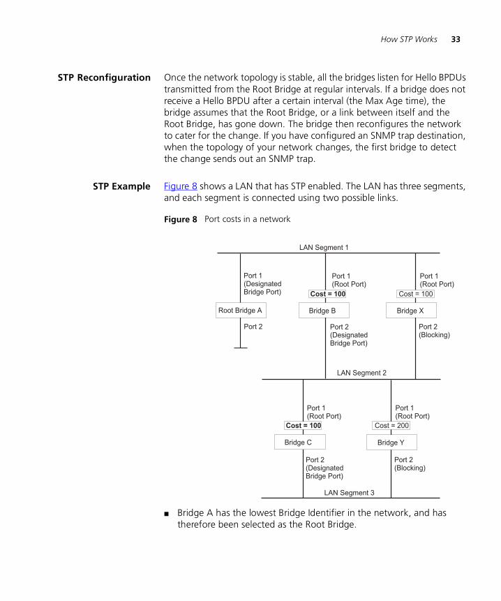
STP Example Figure 8 shows a LAN that has STP enabled. The LAN has three segments, and each segment is connected using two possible links.
Figure 8 Port costs in a network
■ Bridge A has the lowest Bridge Identifier in the network, and has therefore been selected as the Root Bridge.

34 CHAPTER 4: USING RESILIENCE FEATURES
■ Because Bridge A is the Root Bridge, it is also the Designated Bridge for LAN segment 1. Port 1 on Bridge A is therefore selected as the Designated Bridge Port for LAN Segment 1.
■ Port 1 of Bridges B, C, X and Y have been defined as Root Ports because they are the nearest to the Root Bridge and therefore have the most efficient path.
■ Bridges B and X offer the same Root Path Cost for LAN segment 2, however, Bridge B has been selected as the Designated Bridge for the segment because it has a lower Bridge Identifier. Port 2 on Bridge B is therefore selected as the Designated Bridge Port for LAN Segment 2.
■ Bridge C has been selected as the Designated Bridge for LAN segment 3, because it offers the lowest Root Path Cost for LAN Segment 3:
■ the route through Bridges C and B costs 200 (C to B=100, B to A=100)
■ the route through Bridges Y and B costs 300 (Y to B=200, B to A=100).
Port 2 on Bridge C is therefore selected as the Designated Bridge Port for LAN Segment 3.
STP Configurations Figure 9 shows three possible STP configurations using SuperStack 3 Switch units.
■ Configuration 1 — Redundancy for Backbone Link
In this configuration, the Switches both have STP enabled and are connected by two links. STP discovers a duplicate path and blocks one of the links. If the enabled link breaks, the disabled link becomes re-enabled, therefore maintaining connectivity.
■ Configuration 2 — Redundancy through Meshed Backbone
In this configuration, four Switch units are connected in a way that creates multiple paths between each one. STP discovers the duplicate paths and blocks two of the links. If an enabled link breaks, one of the disabled links becomes re-enabled, therefore maintaining connectivity.
■ Configuration 3 — Redundancy for Cabling Error
In this configuration, a Switch has STP enabled and is accidentally connected to a hub using two links. STP discovers a duplicate path and blocks one of the links, therefore avoiding a loop.

How STP Works 35
Figure 9 STP configurations

36 CHAPTER 4: USING RESILIENCE FEATURES
Using STP on a Network with Multiple VLANs
Your Switch does not take into account VLANs when it calculates STP information — the calculations are only performed on the basis of physical connections. For this reason, some network configurations can result in VLANs being subdivided into a number of isolated sections by the STP system.
For example, Figure 10 shows a network containing VLANs 1 and 2. They are connected using the 802.1Q-tagged link between Switch B and Switch C. By default, this link has a path cost of 100 and is automatically blocked because the other Switch-to-Switch connections have a path cost of 36 (18+18). This means that both VLANs are now subdivided — VLAN 1 on Switch units A and B cannot communicate with VLAN 1 on Switch C, and VLAN 2 on Switch units A and C cannot communicate with VLAN 2 on Switch B.
Figure 10 Configuration that separates VLANs
To avoid any VLAN subdivision, 3Com recommends that all inter-Switch connections are made members of all available 802.1Q VLANs to ensure connectivity at all times. For example, the connections between Switches A and B, and between Switches A and C should be 802.1Q tagged and carrying VLANs 1 and 2 to ensure connectivity.
For more information about VLAN Tagging, see Chapter 8 “Setting Up Virtual LANs”.

5
USING THE SWITCH DATABASEWhat is the Switch Database?
The Switch Database is used by the Switch to determine where a packet should be forwarded to, and which port should transmit the packet if it is to be forwarded.
The database contains a list of entries — each entry contains three items:
■ MAC (Ethernet) address information of the endstation that sends packets to the Switch.
■ Port identifier, that is the port attached to the endstation that is sending the packet.
■ VLAN ID of the VLAN to which the endstation belongs.
For details of the number of addresses supported by your Switch database, please refer to Chapter 1 of the Getting Started Guide that accompanies your Switch.
How Switch Database Entries Get Added
Entries are added to the Switch Database in one of two ways:
■ The Switch can learn entries. The Switch updates its database with the source MAC address of the endstation that sent the packet, the VLAN ID, and the port identifier on which the packet is received.
■ You can enter and update entries using the managment interface, or an SNMP Network Manager.

38 CHAPTER 5: USING THE SWITCH DATABASE
Switch Database Entry States
Databases entries can have three states:
■ Learned — The Switch has placed the entry into the Switch Database when a packet was received from an endstation. Note that:
■ Learned entries are removed (aged out) from the Switch Database if the Switch does not receive further packets from that endstation within a certain period of time (the aging time). This prevents the Switch Database from becoming full with obsolete entries by ensuring that when an endstation is removed from the network, its entry is also removed from the database.
■ Learned entries are removed from the Switch Database if the Switch is reset or powered-down.
■ Non-aging learned — If the aging time is set to 0 seconds, all learned entries in the Switch Database become non-aging learned entries. This means that they are not aged out, but they are still removed from the database if the Switch is reset or powered-down.
■ Permanent — The entry has been placed into the Switch Database using the management interface. Permanent entries are not removed from the Switch Database unless they are removed using the Switch management interface or the Switch is initialized.
6
USING TRAFFIC PRIORITIZATIONUsing the traffic prioritization capabilities of your Switch allows you to prioritise your network traffic to ensure that high priority data is transmitted with minimum delay.
This chapter explains more about traffic prioritization.
For a list of the features supported by your Switch, please refer to Chapter 1 of the Getting Started Guide that accompanies your Switch.
What is Traffic Prioritization?
Traffic prioritization allows high priority data, such as time-sensitive and system-critical data to be transferred smoothly and with minimal delay over a network.
This system is compatible with the relevant sections of the IEEE 802.1D/D17 standard (incorporating IEEE 802.1p).
Traffic prioritization is most useful for critical applications that require a high Class of Service (CoS) from the network. These could include:
■ Converged network applications — Used by organizations with a converged network, that is, a network that uses the same infrastructure for voice and video data and traditional data. Organizations that require high quality voice and video data transmission at all times can ensure this by maximising bandwidth and providing low latency.
■ Resource planning applications — Used by organizations that require predictable and reliable access to enterprise resource planning applications such as SAP.
■ Financial applications — Used by Accounts departments that need immediate access to large files and spreadsheets at the end of the month.

40 CHAPTER 6: USING TRAFFIC PRIORITIZATION
■ CAD/CAM design applications — Design departments that need priority connections to server farms and other devices for transferring large files.
How TrafficPrioritization Works
Traffic prioritization ensures that high priority data is forwarded through the Switch without being obstructed by lower priority data. Traffic prioritization uses the multiple traffic queues that are present in the hardware of the Switch to ensure that high priority traffic is forwarded on a different queue from lower priority traffic, and is given preference over that traffic. This ensures that time-sensitive traffic gets the highest Class of Service (CoS).
CoS differentiates traffic into classes and prioritizing those classes automatically.
The 802.1D standard specifies eight distinct levels of priority (0 to 7), each of which relates to a particular type (class) of traffic. The priority levels and their traffic types are shown in Table 5 in order of increasing priority.
You cannot alter the mapping of the priorities as this is fixed (as defined in IEEE 802.1D).
Table 5 IEEE 802.1D Priority levels and traffic types
The transmitting endstation sets the priority of each packet. The Switch receives the packet from the endstation and is able to recognize and process all eight levels. The Switch then maps the packets internally to the appropriate priority queue for onward transmission across the network.
IEEE 802.1D Priority Level IEEE 802.1D Traffic Type
0 (Default) Best Effort
1 Background
2 Standard (spare)
3 Excellent Effort (business critical)
4 Controlled Load (streaming multimedia)
5 Video (Interactive media), less than 100 milliseconds latency and jitter.
6 Voice (Interactive voice), less than 10 milliseconds latency and jitter.
7 Network Control Reserved traffic

What is Traffic Prioritization? 41
Traffic Prioritizationand Your Switch
The Switch 4300 has two priority queues set as default (high and low). The Switch maps 802.1D priority level 0-3 traffic to the low priority queue, and maps the priority level 4-7 traffic to the high priority queue.
Queues cannot be enabled on a per-port basis.
You cannot alter the number of priority queues — this is fixed at two (default).
The Switch 4300 uses the Strict Priority method of selecting data for transmission. That is, the data is selected from a queue for onward transmission only if all the higher queues are empty.
Default Port Priority
If an untagged packet is received against a port, the packet is given default priority to pass through the Switch.

42 CHAPTER 6: USING TRAFFIC PRIORITIZATION

7
STATUS MONITORING AND STATISTICSThis chapter contains details of the features that assist you with status monitoring and statistics. It covers the following topics:
■ Roving Analysis Port (RAP)
■ Remote Monitoring (RMON)
For a list of the features supported by your Switch, please refer to Chapter 1 of the Getting Started Guide that accompanies your Switch.
Roving Analysis Port (RAP)
Roving analysis is a system that allows you to attach a network analyzer to one port and use it to monitor the traffic of other ports on the Switch. The system works by enabling you to define an analysis port (the port that is connected to the analyzer), and a monitor port (the port that is to be monitored). Once the pair are defined, and you start monitoring, the Switch takes all the traffic going in and out of the monitor port and copies it to the analysis port.
Roving analysis is used when you need the functions of a network analyzer, but do not want to change the physical characteristics of the monitored segment by attaching an analyzer to that segment.
Roving Analysis andthe Switch 4300
When setting up a port for roving analysis, note the following:
■ You can only set up roving analysis on ports operating at the same speed, for example, 10 Mbps ports cannot be mirrored to a 100 Mbps port, and vice versa.
■ You cannot set up roving analysis between a front panel port and a downlink module gigabit ethernet port.
■ Only one roving analysis port can be set up per unit.

44 CHAPTER 7: STATUS MONITORING AND STATISTICS
RMON Using the RMON capabilities of a Switch allows you to improve your network efficiency and reduce the load on your network.
This section explains more about RMON. It covers the following topics:
■ What is RMON?
■ Benefits of RMON
■ RMON and the Switch 4300
You can only use the RMON features of the Switch if you have an RMON management application.
What is RMON? RMON is a system defined by the IETF (Internet Engineering Task Force) that allows you to monitor the traffic of LANs or VLANs remotely.
A typical RMON setup consists of two components:
■ The RMON probe — An intelligent, remotely-controlled device or software agent that continually collects statistics about a LAN segment or VLAN, and transfers the information to a management workstation on request or when a pre-defined threshold is crossed.
■ The management workstation — Communicates with the RMON probe and collects the statistics from it. The workstation does not have to be on the same network as the probe and can manage the probe by in-band or out-of-band connections.
The RMON Groups The IETF define groups of Ethernet RMON statistics. This section describes seven groups, and details how you can use them.
Refer to Table 6 on page 47 for details of which RMON groups are supported by your Switch.
Statistics
The Statistics group provides traffic and error statistics showing packets, bytes, broadcasts, multicasts and errors on a LAN segment or VLAN.
Information from the Statistics group is used to detect changes in traffic and error patterns in critical areas of your network.

What is RMON? 45
History
The History group provides historical views of network performance by taking periodic samples of the counters supplied by the Statistics group.
The group is useful for analyzing the traffic patterns and trends on a LAN segment or VLAN, and for establishing the normal operating parameters of your network.
Alarms
The Alarms group provides a mechanism for setting thresholds and sampling intervals to generate events on any RMON variable.
Alarms are used to inform you of network performance problems and they can trigger automated responses through the Events group.
Hosts
The Hosts group specifies a table of traffic and error statistics for each host (endstation) on a LAN segment or VLAN. Statistics include packets sent and received, octets sent and received, as well as broadcasts, multicasts, and error packets received.
The group supplies a list of all hosts that have transmitted across the network.
Hosts Top N
This group requires implementation of the Hosts group. The Hosts Top N group extends the Hosts table by providing sorted host statistics, such as the top 20 hosts sending packets or an ordered list of all hosts according to the errors they sent over the last 24 hours.
Matrix
The Matrix group shows the amount of traffic and number of errors between pairs of devices on a LAN segment or VLAN. For each pair, the Matrix group maintains counters of the number of packets, number of octets, and number of error packets between the hosts.
The conversation matrix helps you to examine network statistics in more detail to discover, for example, who is talking to whom or if a particular PC is producing more errors when communicating with its file server. Combined with Hosts Top N, this allows you to view the busiest hosts and their primary conversation partners.
46 CHAPTER 7: STATUS MONITORING AND STATISTICS
Events
The Events group provides you with the ability to create entries in an event log and send SNMP traps to the management workstation. Events are the action that can result from an RMON alarm. In addition to the standard five traps required by SNMP (link up, link down, warm start, cold start, and authentication failure), RMON adds two more: rising threshold and falling threshold.
Effective use of the Events group saves you time; rather than having to watch real-time graphs for important occurrences, you can depend on the Event group for notification. Through the SNMP traps, events can trigger other actions, therefore providing a way to automatically respond to certain occurrences.
Benefits of RMON Using the RMON features of your Switch has three main advantages:
■ It improves your efficiency
Using RMON probes allows you to remain at one workstation and collect information from widely dispersed LAN segments or VLANs. This means that the time taken to reach a problem site, set up equipment, and begin collecting information is largely eliminated.
■ It allows you to manage your network in a more proactive manner
If they are configured correctly, RMON probes deliver information before problems occur. This means that you can take action before they affect users. In addition, probes record the behavior of your network, so that you can analyze the causes of problems.
■ It reduces the load on the network and the management workstation
Traditional network management involves a management workstation polling network devices at regular intervals to gather statistics and identify problems or trends. As network sizes and traffic levels grow, this approach places a strain on the management workstation and also generates large amounts of traffic.
An RMON probe, however, autonomously looks at the network on behalf of the management workstation without affecting the characteristics and performance of the network. The probe reports by

RMON and the Switch 4300 47
exception, which means that it only informs the management workstation when the network has entered an abnormal state.
RMON and the Switch 4300
Your Switch contains an RMON probe in its management software. Table 6 details the RMON support provided by this built-in probe.
When using the RMON features of the Switch, note the following:
■ After the default sessions are created, they have no special status. You can delete or change them as required.
■ The greater the number of RMON sessions, the greater the burden on the management resources of the Switch. If you have many RMON sessions, the forwarding performance of the Switch is not affected but you may experience slow response times from the web interface.
Alarm Events You can define up to 8 alarms for the Switch. The events that you can define for each alarm and their resulting actions are listed in Table 7.
Table 6 RMON support supplied by the Switch 4300
RMON group Support supplied by the Switch
Statistics A new or initialized Switch has one Statistics session per port.
History A new or initialized Switch has two History sessions per port.
These sessions provide the data for the web interface history displays:
■ 600 second intervals, 6 historical samples stored
■ 1 hour intervals, 6 historical samples stored
Alarms A new or initialized Switch has a Broadcast bandwidth used alarm defined for each port:
You can modify this alarm using an RMON management application, but you cannot create or delete them.
You can define up to 8 alarms for the Switch.
For more information about the alarms setup on the Switch, see “Alarm Events” on page 47 and “The Default Alarm Settings” on page 48.
Events A new or initialized Switch has Events defined for use with the default alarm system. See “The Default Alarm Settings” on page 48 for more information.

48 CHAPTER 7: STATUS MONITORING AND STATISTICS
The Default AlarmSettings
A new or initialized Switch has a Broadcast bandwidth used alarm defined for each port.
The default values and actions for this alarm is given in Table 8.
Table 7 Alarm Events
Event Action
No action
Notify only Send Trap.
Notify and filter port Send Trap. Block broadcast and multicast traffic on the port. Recovers with the unfilter port event.
Notify and disable port Send Trap. Turn port off.
Notify and enable port Send Trap. Turn port on.
Disable port Turn port off.
Enable port Turn port on.
Notify and unfilter port Send Trap. Stop blocking broadcast and multicast traffic on the port.
System started
Software Upgrade report
Table 8 Values for the default alarm
Statistic High Threshold Low Threshold Recovery Period
Broadcast bandwidth used
Value: 20%
Action: Notify and filter
Value: 10%
Action: Notify and unfilter
30 secs

8
SETTING UP VIRTUAL LANSSetting up Virtual LANs (VLANs) on your Switch reduces the time and effort required by many network administration tasks, and increases the efficiency of your network.
This chapter explains more about the concept of VLANs and explains how they can be implemented on your Switch. It covers the following topics:
■ What are VLANs?
■ Benefits of VLANs
■ VLANs and Your Switch
■ VLAN Configuration Examples
What are VLANs? A VLAN is a flexible group of devices that can be located anywhere in a network, but which communicate as if they are on the same physical segment. With VLANs, you can segment your network without being restricted by physical connections — a limitation of traditional network design. As an example, with VLANs you can segment your network according to:
■ Departmental groups — For example, you can have one VLAN for the Marketing department, another for the Finance department, and another for the Development department.
■ Hierarchical groups — For example, you can have one VLAN for directors, another for managers, and another for general staff.
■ Usage groups — For example, you can have one VLAN for users of e-mail, and another for users of multimedia.

50 CHAPTER 8: SETTING UP VIRTUAL LANS
Figure 11 A network setup showing three VLANs
Benefits of VLANs The main benefit of VLANs is that they provide a network segmentation system that is far more flexible than any traditional network. Using VLANs also provides you with three other benefits:
■ VLANs ease the movement of devices on networks
With traditional networks, network administrators spend much of their time dealing with moves and changes. If users move to a different subnetwork, the addresses of each endstation must be updated manually.
With a VLAN setup, if an endstation in VLAN Marketing is moved to a port in another part of the network, and retains its original subnet membership, you only need to specify that the new port is in VLAN Marketing. You do not need to carry out any re-cabling.
■ VLANs provide extra security
Devices within each VLAN can only communicate with other devices in the same VLAN. If a device in VLAN Marketing needs to communicate with devices in VLAN Finance, the traffic must pass through a routing device or Layer 3 switch.

VLANs and Your Switch 51
■ VLANs help to control traffic
With traditional networks, congestion can be caused by broadcast traffic that is directed to all network devices whether they require it or not. VLANs increase the efficiency of your network because each VLAN can be set up to contain only those devices that need to communicate with each other.
VLANs and Your Switch
Your Switch provides support for VLANs using the IEEE 802.1Q standard. This standard allows traffic from multiple VLANs to be carried across one physical link.
The IEEE 802.1Q standard allows each port on your Switch to be placed in:
■ Any one VLAN defined on the Switch.
■ Several VLANs at the same time using 802.1Q tagging.
The standard requires that you define the following information about each VLAN on your Switch before the Switch can use it to forward traffic:
■ VLAN Name — This is a descriptive name for the VLAN (for example, Marketing or Management).
■ 802.1Q VLAN ID — This is used to identify the VLAN if you use 802.1Q tagging across your network.
The Default VLAN A new or initialized Switch contains a single VLAN, the Default VLAN. This VLAN has the following definition:
■ VLAN Name — Default VLAN
■ 802.1Q VLAN ID — 1
All the ports are initially placed in this VLAN, and it is the only VLAN that allows you to access the management software of the Switch over the network.
Creating New VLANs If you want to move a port from the Default VLAN to another VLAN, you must first define information about the new VLAN on your Switch.

52 CHAPTER 8: SETTING UP VIRTUAL LANS
Untagged andTagged VLANs
Your Switch supports 802.1Q VLAN tagging, a system that allows traffic for multiple VLANs to be carried on a single physical (backbone) link.
When setting up VLANs you need to understand when to use untagged and tagged VLANs. Quite simply, if a port is in a single VLAN it can be untagged but if the port needs to be a member of multiple VLANs it must be tagged.
The IEEE 802.1Q standard defines how VLANs operate within an open packet-switched network. An 802.1Q compliant packet carries additional information that allows a switch to determine to which VLAN the port belongs. If a frame is carrying the additional information, it is known as tagged.
To carry multiple VLANs across a single physical (backbone) link, each packet must be tagged with a VLAN identifier so that the switches can identify which packets belong in which VLANs. Routers interconnect VLANs, so they must also understand 802.1Q tagging, so that they do not become bottlenecks for inter-VLAN traffic.
Placing a Port in aSingle VLAN
Once the information for a new VLAN has been defined, you can place a port in that VLAN.
Creating an IEEE 802.1Q Tagged Link
This method of tagging is defined in the IEEE 802.1Q standard, and allows a link to carry traffic for any of the VLANs defined on your Switch. 802.1Q tagging can only be used if the devices at both ends of a link support IEEE 802.1Q.
To create an 802.1Q tagged link:
1 Ensure that the device at the other end of the link uses the same 802.1Q tags as your Switch, that is, the same VLAN IDs are configured.
2 Place the Switch port in the required VLANs.
3 Place the port at the other end of the link in the same VLANs as the port on your Switch.
Connecting VLANs toOther VLANs
If the devices placed in a VLAN need to communicate to devices in a different VLAN, each VLAN requires a connection to a router or Layer 3 switching device. Communication between VLANs can only take place if they are all connected to a routing or Layer 3 switching device.

VLANs and Your Switch 53
Figure 12 Two VLANs connected via a router
54 CHAPTER 8: SETTING UP VIRTUAL LANS
VLAN Configuration Examples
This section contains examples of simple VLAN configurations. It describes how to set up your switch to support simple untagged and tagged connections.
Using UntaggedConnections
The simplest VLAN operates in a small network using a single switch. In this network there is no requirement to pass VLAN traffic across a link. All traffic is handled by the single Switch and therefore untagged connections can be used.
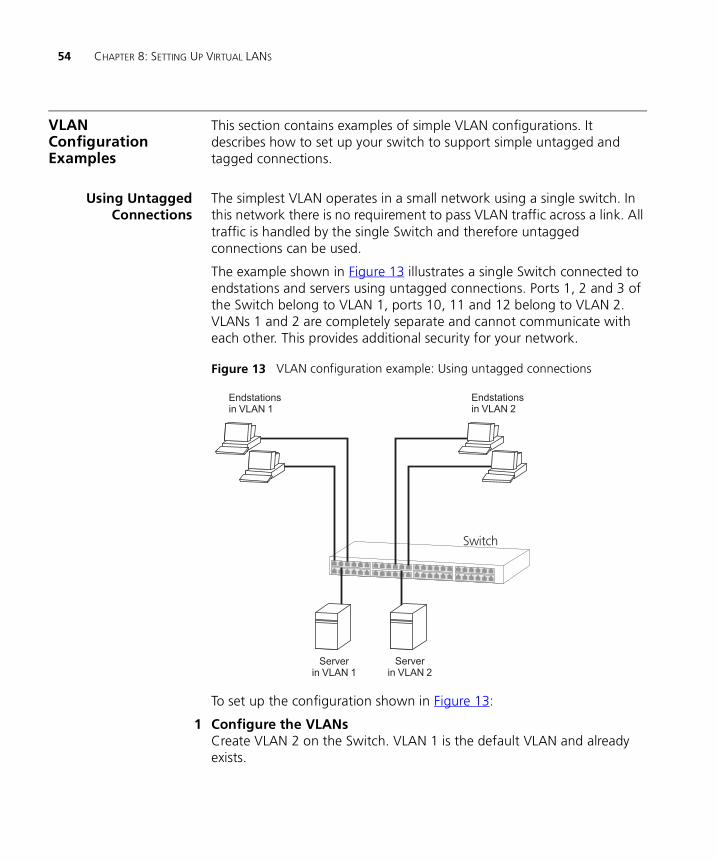
The example shown in Figure 13 illustrates a single Switch connected to endstations and servers using untagged connections. Ports 1, 2 and 3 of the Switch belong to VLAN 1, ports 10, 11 and 12 belong to VLAN 2. VLANs 1 and 2 are completely separate and cannot communicate with each other. This provides additional security for your network.
Figure 13 VLAN configuration example: Using untagged connections
To set up the configuration shown in Figure 13:
1 Configure the VLANs Create VLAN 2 on the Switch. VLAN 1 is the default VLAN and already exists.

VLAN Configuration Examples 55
2 Add ports to the VLANs
a Place ports 1, 2 and 3 of the Switch in VLAN 1.
b Place ports 10, 11 and 12 of the Switch in VLAN 2.
Using 802.1Q TaggedConnections
In a network where the VLANs are distributed amongst more than one Switch, you must use 802.1Q tagged connections so that all VLAN traffic can be passed along the link between the Switches.
The example shown in Figure 14 illustrates two Switch units. Each switch has endstations in VLAN 1 and VLAN 2 and each Switch has a server for a VLAN. All endstations in VLAN 1 need to be able to connect to the server attached to Switch 1 and all endstations in VLAN 2 need to connect to the server attached to Switch 2.
Figure 14 VLAN configuration example: 802.1Q tagged connections
To set up the configuration shown in Figure 14:
1 Configure the VLANs on Switch 1Define VLAN 2. VLAN 1 is the default VLAN and already exists.
2 Add untagged ports on Switch 1Place untagged ports in the appropriate VLAN

56 CHAPTER 8: SETTING UP VIRTUAL LANS
3 Add tagged port 12 on Switch 1Assign port 12 on Switch 1 to both VLANs 1 and 2 so that all VLAN traffic is passed over the link to Switch 2.
4 Configure the VLANs on Switch 2Define VLAN 2. VLAN 1 is the default VLAN and already exists.
5 Add untagged ports on Switch 2Place untagged ports in the appropriate VLAN
6 Add tagged port 11 on Switch 2Assign port 11 on Switch 2 to both VLANs 1 and 2 so that all VLAN traffic is passed over the link to Switch 1.
7 Check the VLAN membership for both switchesThe relevant ports should be listed in the VLAN members summary.
8 Connect the switchesConnect port 12 on Switch 1 to port 11 on Switch 2.
The VLANs are now configured and operational and the endstations in both VLANs can communicate with their relevant servers.

II
APPENDICES AND INDEXAppendix A Configuration Rules
Appendix B Network Configuration Examples
Glossary
Index

58
A
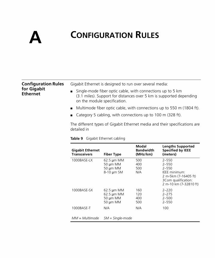
CONFIGURATION RULESConfiguration Rules for Gigabit Ethernet
Gigabit Ethernet is designed to run over several media:
■ Single-mode fiber optic cable, with connections up to 5 km (3.1 miles). Support for distances over 5 km is supported depending on the module specification.
■ Multimode fiber optic cable, with connections up to 550 m (1804 ft).
■ Category 5 cabling, with connections up to 100 m (328 ft).
The different types of Gigabit Ethernet media and their specifications are detailed in
Table 9 Gigabit Ethernet cabling
Gigabit EthernetTransceivers Fiber Type
Modal Bandwidth(MHz/km)
Lengths SupportedSpecified by IEEE(meters)
1000BASE-LX
1000BASE-SX
1000BASE-T
MM = Multimode
62.5 µm MM50 µm MM50 µm MM8-10 µm SM
62.5 µm MM62.5 µm MM50 µm MM50 µm MM
N/A
SM = Single-mode
500400500N/A
160120400500
N/A
2–5502–5502–550IEEE minimum: 2 m-5km (7-16405 ft)3Com qualification: 2 m-10 km (7-32810 ft)
2–2202–2752–5002–550
100

60 APPENDIX A: CONFIGURATION RULES
Configuration Rules for Fast Ethernet
The topology rules for 100 Mbps Fast Ethernet are slightly different to those for 10 Mbps Ethernet. Figure 15 illustrates the key topology rules and provides examples of how they allow for large-scale Fast Ethernet networks.
Figure 15 Fast Ethernet configuration rules
The key topology rules are:
■ Maximum UTP cable length is 100 m (328 ft) over Category 5 cable.
■ A 412 m (1352 ft) fiber link is allowed for connecting switch-to-switch, or endstation-to-switch, using half-duplex 100BASE-FX.
■ A total network span of 325 m (1066 ft) is allowed in single-repeater topologies (one hub stack per wiring closet with a fiber link to the

Configuration Rules for Fast Ethernet 61
collapsed backbone). For example, a 225 m (738 ft) fiber link from a repeater to a router or switch, plus a 100 m (328 ft) UTP link from a repeater out to the endstations.
Configuration Ruleswith Full Duplex
The Switch provides full duplex support for all its ports, including Expansion Module ports. Full duplex allows packets to be transmitted and received simultaneously and, in effect, doubles the potential throughput of a link.
With full duplex, the Ethernet topology rules are the same, but the Fast Ethernet rules are:
■ Maximum UTP cable length is 100 m (328 ft) over Category 5 cable.
■ A 2 km (6562 ft) fiber link is allowed for connecting switch-to-switch, or endstation-to-switch.

62 APPENDIX A: CONFIGURATION RULES

B
NETWORK CONFIGURATION EXAMPLESThis chapter contains the following sections:
■ Network Configuration Examples
■ Segmentation Switch Example
■ Collapsed Backbone Switch Example
■ Desktop Switch Example
Where a Switch 4900 is shown, this is interchangeable with the Switch 4900 SX.
64 APPENDIX B: NETWORK CONFIGURATION EXAMPLES
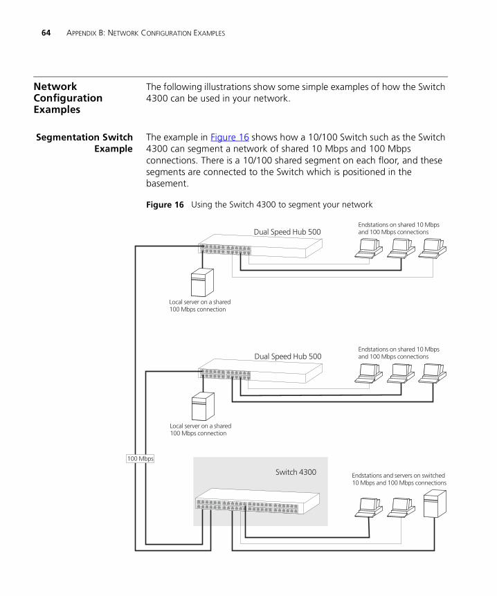
Network Configuration Examples
The following illustrations show some simple examples of how the Switch 4300 can be used in your network.
Segmentation SwitchExample
The example in Figure 16 shows how a 10/100 Switch such as the Switch 4300 can segment a network of shared 10 Mbps and 100 Mbps connections. There is a 10/100 shared segment on each floor, and these segments are connected to the Switch which is positioned in the basement.
Figure 16 Using the Switch 4300 to segment your network

Network Configuration Examples 65
Collapsed BackboneSwitch Example
The example in Figure 17 shows how a Switch 4300 can act as a backbone for both shared and switched network segments.
Figure 17 Using the Switch 4300 as a collapsed backbone

66 APPENDIX B: NETWORK CONFIGURATION EXAMPLES
Desktop SwitchExample
The example in Figure 18 shows how a Switch 4300 can be used for a group of users that require dedicated 10 Mbps or 100 Mbps connections to the desktop. The Switch 4300 has a 1000BASE-T Module fitted that allows it to provide a Gigabit Ethernet link to a Switch 4900 in the basement.
Figure 18 Using the Switch 4300 in a desktop environment

GLOSSARY
10BASE-T The IEEE specification for 10 Mbps Ethernet over Category 3, 4 or 5 twisted pair cable.
100BASE-FX The IEEE specification for 100 Mbps Fast Ethernet over fiber-optic cable.
100BASE-TX The IEEE specification for 100 Mbps Fast Ethernet over Category 5 twisted-pair cable.
1000BASE-T The IEEE specification for 1000 Mbps Gigabit Ethernet over four-pair Category 5 twisted-pair cable.
1000BASE-SX The IEEE specification for 1000 Mbps Gigabit Ethernet over fiber-optic cable.
aging The automatic removal of dynamic entries from the Switch Database which have timed-out and are no longer valid.
Aggregated Links Aggregated links allow a user to increase the bandwidth and resilience between switches by using a group of ports to carry traffic between the switches.
auto-negotiation A feature on twisted pair ports that allows them to advertise their capabilities for speed, duplex and flow control. When connected to a port that also supports auto-negotiation, the link can automatically configure itself to the optimum setup.
backbone The part of a network used as a primary path for transporting traffic between network segments.
bandwidth The information capacity, measured in bits per second, that a channel can transmit. The bandwidth of Ethernet is 10 Mbps, the bandwidth of Fast Ethernet is 100 Mbps, and the bandwidth of Gigabit Ethernet is 1000 Mbps.
68 GLOSSARY
baud The signalling rate of a line, that is, the number of transitions (voltage or frequency changes) made per second. Also known as line speed.
BOOTP The BOOTP protocol allows you to automatically map an IP address to a given MAC address each time a device is started. In addition, the protocol can assign the subnet mask and default gateway to a device.
bridge A device that interconnects two LANs of a different type to form a single logical network that comprises of two network segments.
Bridges learn which endstations are on which network segment by examining the source addresses of packets. They then use this information to forward packets based on their destination address. This process is known as filtering.
broadcast A packet sent to all devices on a network.
broadcast storm Multiple simultaneous broadcasts that typically absorb all the available network bandwidth and can cause a network to fail. Broadcast storms can be due to faulty network devices.
collision A term used to describe two colliding packets in an Ethernet network. Collisions are a part of normal Ethernet operation, but a sudden prolonged increase in the number of collisions can indicate a problem with a device, particularly if it is not accompanied by a general increase in traffic.
CSMA/CD Carrier-sense Multiple Access with Collision Detection. The protocol defined in Ethernet and IEEE 802.3 standards in which devices transmit only after finding a data channel clear for a period of time. When two devices transmit simultaneously, a collision occurs and the colliding devices delay their retransmissions for a random length of time.
endstation A computer, printer or server that is connected to a network.
Ethernet A LAN specification developed jointly by Xerox, Intel and Digital Equipment Corporation. Ethernet networks use CSMA/CD to transmit packets at a rate of 10 Mbps over a variety of cables.
Ethernet address See MAC address.
Fast Ethernet An Ethernet system that is designed to operate at 100Mbps.
forwarding The process of sending a packet toward its destination using a networking device.

69
Forwarding Database See Switch Database.
filtering The process of screening a packet for certain characteristics, such as source address, destination address, or protocol. Filtering is used to determine whether traffic is to be forwarded, and can also prevent unauthorized access to a network or network devices.
flow control A mechanism that prevents packet loss during periods of congestion on the network. Packet loss is caused when devices send traffic to an already overloaded port on a Switch. Flow control prevents packet loss by inhibiting devices from generating more traffic until the period of congestion ends.
full duplex A system that allows packets to be transmitted and received at the same time and, in effect, doubles the potential throughput of a link.
Gigabit Ethernet IEEE standard 802.3z for 1000 Mbps Ethernet; it is compatible with existing 10/100 Mbps Ethernet standards.
half duplex A system that allows packets to transmitted and received, but not at the same time. Contrast with full duplex.
hub A device that regenerates LAN traffic so that the transmission distance of that signal can be extended. Hubs are similar to repeaters, in that they connect LANs of the same type; however they connect more LANs than a repeater and are generally more sophisticated.
IEEE Institute of Electrical and Electronics Engineers. This American organization was founded in 1963 and sets standards for computers and communications.
IEEE 802.1D A standard that defines the behavior of bridges in an Ethernet network.
IEEE 802.1p A standard that defines traffic prioritization. 802.1p is now incorporated into the relevant sections of the IEEE 802.1D/D17 standard.
IEEE 802.1Q A standard that defines VLAN tagging.
IEEE 802.3x A standard that defines a system of flow control for ports that operate in full duplex.
IETF Internet Engineering Task Force. An organization responsible for providing engineering solutions for TCP/IP networks. In the network

70 GLOSSARY
management area, this group is responsible for the development of the SNMP protocol.
IFM Intelligent Flow Management. A flow control mechanism that prevents packet loss during periods of congestion on the network.
Internet GroupManagement
Protocol
Internet Group Management Protocol (IGMP) is a protocol that runs between hosts and their immediate neighboring multicast routers. The protocol allows a host to inform its local router that it wishes to receive transmissions addressed to a specific multicast group. Based on group membership information learned from the IGMP, a router is able to determine which if any multicast traffic needs to be forwarded to each of its subnetworks.
IGMP snooping A mechanism performed by intermediate systems that optimizes the flow of multicast traffic; these intermediate systems (such as Layer 2 switches) listen for IGMP messages and build mapping tables and associated forwarding filters, in addition to reducing the IGMP protocol traffic.
IP Internet Protocol. IP is a layer 3 network protocol that is the standard for sending data through a network. IP is part of the TCP/IP set of protocols that describe the routing of packets to addressed devices.
IPX Internetwork Packet Exchange. IPX is a layer 3 and 4 network protocol designed for networks that use Novell® Netware®.
IP address Internet Protocol address. A unique identifier for a device attached to a network using TCP/IP. The address is written as four octets separated with periods (full-stops), and is made up of a network section, an optional subnet section and a host section.
Jitter An expression often used to describe the end-to-end delay variations during the course of a transmission. See also latency.
LAN Local Area Network. A network of endstations (such as PCs, printers, servers) and network devices (hubs and switches) that cover a relatively small geographic area (usually not larger than a floor or building). LANs are characterized by high transmission speeds over short distances (up to 1000 m).
LLC Logical Link Control. A sublayer of the IEEE data link layer that is located above the MAC sublayer. The LLC sublayer is responsible for MAC sublayer addressing, flow control, error control, and framing.

71
latency The delay between the time a device receives a packet and the time the packet is forwarded out of the destination port.
line speed See baud.
loop An event that occurs when two network devices are connected by more than one path, thereby causing packets to repeatedly cycle around the network and not reach their destination.
MAC Media Access Control. A protocol specified by the IEEE for determining which devices have access to a network at any one time.
MAC address Media Access Control address; also called hardware or physical address. A layer 2 address associated with a particular network device. Most devices that connect to a LAN have a MAC address assigned to them as they are used to identify other devices in a network. MAC addresses are 6 bytes long.
main port The port in a resilient link that carries data traffic in normal operating conditions.
MDI Medium Dependent Interface. An Ethernet port connection where the transmitter of one device is connected to the receiver of another device.
MDI-X Medium Dependent Interface Cross-over. An Ethernet port connection where the internal transmit and receive lines are crossed.
MIB Management Information Base. A collection of information about the management characteristics and parameters of a networking device. MIBs are used by the Simple Network Management Protocol (SNMP) to gather information about the devices on a network. The Switch contains its own internal MIB.
multicast A packet sent to a specific group of endstations on a network.
multicast filtering A system that allows a network device to only forward multicast traffic to an endstation if it has registered that it would like to receive that traffic.
NIC Network Interface Card. A circuit board installed in an endstation that allows it to be connected to a network.
POST Power On Self Test. An internal test that a Switch carries out when it is powered-up.

72 GLOSSARY
protocol A set of rules for communication between devices on a network. The rules dictate format, timing, sequencing and error control.
repeater A simple device that regenerates LAN traffic so that the transmission distance of that signal can be extended. Repeaters are used to connect two LANs of the same network type.
resilient link A pair of ports that can be configured so that one takes over data transmission should the other fail. See also main port and standby port.
RMON IETF Remote Monitoring MIB. A MIB that allows you to remotely monitor LANs by addressing up to nine different groups of information.
router A device that provides WAN links between geographically separate networks.
roving analysis port(RAP)
A system that allows you to copy the traffic from one port on a Switch to another port on the Switch. Roving Analysis is used when you want to monitor the physical characteristics of a LAN segment without changing the characteristics by attaching a monitoring device.
RPS Redundant Power System. A device that provides a backup source of power when connected to a Switch.
SAP Service Access Point. A well-defined location that identifies the user of services of a protocol entity.
segment A section of a LAN that is connected to the rest of the network using a switch or bridge.
server A computer in a network that is shared by multiple endstations. Servers provide endstations with access to shared network services such as computer files and printer queues.
SLIP Serial Line Internet Protocol. A protocol that allows IP to run over a serial line (console port) connection.
SNMP Simple Network Management Protocol. The current IETF standard protocol for managing devices on an TCP/IP network.
Spanning TreeProtocol (STP)
A bridge-based system for providing fault tolerance on networks. STP works by allowing you to implement parallel paths for network traffic, and ensure that redundant paths are disabled when the main paths are operational and enabled if the main paths fail.
73
stack A group of network devices that are integrated to form a single logical device.
standby port The port in a resilient link that takes over data transmission if the main port in the link fails.
STP See Spanning Tree Protocol (STP).
switch A device that interconnects several LANs to form a single logical LAN that comprises of several LAN segments. Switches are similar to bridges, in that they connect LANs of a different type; however they connect more LANs than a bridge and are generally more sophisticated.
Switch Database A database that is stored by a switch to determine if a packet should be forwarded, and which port should forward the packet if it is to be forwarded. Also known as Forwarding Database.
TCP/IP Transmission Control Protocol/Internet Protocol. This is the name for two of the most well-known protocols developed for the interconnection of networks. Originally a UNIX standard, TCP/IP is now supported on almost all platforms, and is the protocol of the Internet.
TCP relates to the content of the data travelling through a network — ensuring that the information sent arrives in one piece when it reaches its destination. IP relates to the address of the endstation to which data is being sent, as well as the address of the destination network.
Telnet A TCP/IP application protocol that provides a virtual terminal service, letting a user log into another computer system and access a device as if the user were connected directly to the device.
TFTP Trivial File Transfer Protocol. Allows you to transfer files (such as software upgrades) from a remote device using the local management capabilities of the Switch.
traffic prioritization A system which allows data that has been assigned a high priority to be forwarded through a switch without being obstructed by other data.
Transcend® The 3Com umbrella management system used to manage all of 3Com’s networking solutions.
unicast A packet sent to a single endstation on a network.
VLAN Virtual LAN. A group of location- and topology-independent devices that communicate as if they are on the same physical LAN.

74 GLOSSARY
VLAN tagging A system that allows traffic for multiple VLANs to be carried on a single link.
WAN Wide Area Network. A communications network that covers a wide area. A WAN can cover a large geographic area, and may contain several LANs within it.

INDEX
Numbers802.1D 40802.1Q tagging 52
Aaggregated links 14, 20aging time, definition 38alarm events 48alarm settings, default 48Alarms (RMON group) 45, 47auto-negotiation 14, 20
Bbandwidth 19BOOTP 13BPDUs. See Bridge Protocol Data UnitsBridge Identifier 31Bridge Protocol Data Units 31
Ccable
maximum length 60, 61Capture (RMON group) 47CD-ROM 9Class of Service 40conventions
notice icons, About This Guide 8text, About This Guide 8
CoS (see Class of Service) 40
DDefault VLAN 51Designated Bridge 32Designated Bridge Port 32
EEvents (RMON group) 46, 47
FFast Ethernet configuration rules 60Filter (RMON group) 46, 47flow control 20full duplex configuration rules 61
GGigabit Ethernet configuration rules 59glossary 67
HHello BPDUs 33History (RMON group) 45, 47Hosts (RMON group) 45, 47Hosts Top N (RMON group) 45, 47
IIEEE 802.1Q 51IEEE 802.3x flow control 15, 20IGMP multicast filtering 26
Llearned SDB entries 38
MMatrix (RMON group) 45, 47Max Age 33multicast filtering 25
IGMP 26multicasts, description 25
Nnon-aging learned SDB entries 38
Ppath costs. See port costspermanent SDB entries 38

76 INDEX
port costs, default 32port trunks
example 24priority in STP 31
RRemote Monitoring. See RMONRMON 16
alarm events 48benefits 46default alarm settings 48groups 44probe 44
Root Bridge 31Root Path Cost 32Root Port 32
SSDB. See Switch Databasesegment, maximum length 60Spanning Tree Protocol, see STP 29Statistics (RMON group) 44, 47STP 29
avoiding the subdivision of VLANs 36Bridge Identifier 31Bridge Protocol Data Units 31default port costs 32default priority 31Designated Bridge 32Designated Bridge Port 32example 33Hello BPDUs 33Max Age 33priority 31Root Bridge 31Root Path Cost 32Root Port 32using on a network with multiple VLANs 36
Switch Database 37
Ttopology rules for Fast Ethernet 60topology rules with full duplex 61traffic prioritization 39
802.1D 40Class of Service 40
VVLANs 49
802.1Q tagging 52benefits 50Default 51defining the information for 51IEEE 802.1Q 51placing ports in multiple 52