Embed Size (px)
Citation preview

1 www.zensol.com
Copyright © 1992 to 2012 – All Rights reserved worldwide
DIAGNOSTIC/TYPICAL SIGNATURES
February 1st, 2013

2 www.zensol.com
Copyright © 1992 to 2012 – All Rights reserved worldwide
Contents per Brand and Model CONTENTS PER BRAND AND MODEL ....................................................................................................................................................................................................................................... 2
CONTENTS PER PROBLEM ........................................................................................................................................................................................................................................................ 5
#1 ABB – UC (B, C, D, G AND L) AND UZ (B, C, D, E AND F) - BRAID IMPROPERLY INSTALLED ........................................................................................................................................... 9
#2 ABB – UC (B, C, D, G AND L) AND UZ (B, C, D, E AND F) - BENDING OF THE MOVING MAIN CONTACT ARM .............................................................................................................. 10
#3 ABB – UC (B, C, D, G AND L) AND UZ (B, C, D, E AND F) - LACK OF LUBRICATION OF THE CONTROL GEAR ................................................................................................................. 11
#4 ABB – UC (B, C, D, G AND L) AND UZ (B, C, D, E AND F) - SLACK IN THE CONTROL ROD ............................................................................................................................................. 12
#5 ABB – UC (B, C, D, G AND L) AND UZ (B, C, D, E AND F) - ADVANCED WEAR OF THE WHEEL SWITCH ........................................................................................................................ 13
#6 ABB – UC (B, C, D, G AND L) AND UZ (B, C, D, E AND F) - FAULTY CONTROL RELAY ................................................................................................................................................... 14
#7 ABB – UC (B, C, D, G AND L) - DESYNCHRONIZATION BETWEEN SWITCHES .............................................................................................................................................................. 15
#8 ABB – UC (B, C, D, G AND L) - ANOMALY IN THE VOLTAGE LIMITER DEVICE ............................................................................................................................................................. 16
#9 ABB – UC (B, C, D, G AND L) - TIME OF TRANSITION NOT PERCEPTIBLE .................................................................................................................................................................... 17
#10 ABB – UC (B, C, D, G AND L) - SWITCHING SYNCHRONIZATION ................................................................................................................................................................................. 18
#11 ABB – UC (B, C, D, G AND L) - ALIGNING THE CONTACTS OF THE SELECTOR .............................................................................................................................................................. 19
#12 ABB – UC (B, C, D, G AND L) - ASYMMETRY OF SIGNATURES SWITCHING ................................................................................................................................................................. 20
#13 ABB – UCCRN - CONTACT WEAR BY MISSING IMPACTS ............................................................................................................................................................................................ 21
#14 ABB – UCB - TYPICAL SWITCHING ............................................................................................................................................................................................................................. 22
#15 ABB – UCC - TYPICAL SWITCHING ............................................................................................................................................................................................................................. 23
#16 ABB – UCD - TYPICAL SWITCHING ............................................................................................................................................................................................................................. 24
#17 ABB – UCG - TYPICAL SWITCHING............................................................................................................................................................................................................................. 25
#18 ABB – UCL - TYPICAL SWITCHING ............................................................................................................................................................................................................................. 26
#19 ABB – UC - EXPECTED SIGNATURE ............................................................................................................................................................................................................................ 27
#20 ABB – UZ (B, C, D, E AND F) - BRAKE FAILURE ........................................................................................................................................................................................................... 28
#21 ABB – UZ (B, C, D, E AND F) - BRAKE FAILURE ........................................................................................................................................................................................................... 29

3 www.zensol.com
Copyright © 1992 to 2012 – All Rights reserved worldwide
#22 ABB – UZ (B, C, D, E AND F) - WEAR OF CONTACTS ................................................................................................................................................................................................... 30
#23 ABB – UZ (B, C, D, E AND F) FAULTY CONTROL RELAY ............................................................................................................................................................................................... 31
#24 ABB – UZ - TYPES OF TAPS ........................................................................................................................................................................................................................................ 32
#25 ABB - UZCRN - ARCING CONTACT ............................................................................................................................................................................................................................. 33
#26 ABB – UZCRN - SINGLE OPERATION .......................................................................................................................................................................................................................... 34
#27 ABB – UZC, UZE AND UZF - MULTIPLE OPERATIONS ................................................................................................................................................................................................. 35
#28 ABB – UZC, UZE AND UZF - TYPICAL SWITCHING ...................................................................................................................................................................................................... 36
#29 ABB – UZC, UZE AND UZF - TYPICAL SWITCHING ...................................................................................................................................................................................................... 37
#30 ABB – UZB - TYPICAL SWITCHING ............................................................................................................................................................................................................................. 38
#31 ABB UZ - EXPECTED SIGNATURE ............................................................................................................................................................................................................................... 39
#32 FEDERAL PIONEER – REACTIVE MODELS - EXTENDED LENGTH OF THE BRAKING ...................................................................................................................................................... 40
#33 FEDERAL PIONEER – REACTIVE MODELS - DESYNCHRONIZATION OF THE SWITCHING ............................................................................................................................................. 41
#34 FEDERAL PIONEER – REACTIVE MODELS - LACK OF THE LUBRICATION IN THE DRIVE MECHANISM .......................................................................................................................... 42
#35 FEDERAL PIONEER – REACTIVE MODELS - MOTOR STARTUP CONTACTOR ............................................................................................................................................................... 43
#36 FEDERAL PIONEER – REACTIVE MODELS - NOISE OF VERY HIGH AMPLITUDE SWITCHING ........................................................................................................................................ 44
#37 FEDERAL PIONEER – REACTIVE MODELS - NOISE OF VERY HIGH AMPLITUDE DURING THE OPERATION OF THE INVERTER ...................................................................................... 45
#38 FEDERAL PIONEER – REACTIVE MODELS - NOISE OF THE MECHANISM DURING ITS OPERATION .............................................................................................................................. 46
#39 MR REINHAUSEN – M AND V - WEAR OF CONTACT .................................................................................................................................................................................................. 47
#40 MR REINHAUSEN – M AND V - WEAR OF THE ROLLS OF MAIN CONTACTS ............................................................................................................................................................... 48
#41 MR REINHAUSEN – M AND T - GENERAL WEAR OF THE SWITCH .............................................................................................................................................................................. 49
#42 MR REINHAUSEN – M AND T - WEAR OF CONTACTS ................................................................................................................................................................................................ 50
#43 MR REINHAUSEN – M AND MS - TYPICAL SWITCHING .............................................................................................................................................................................................. 51
#44 MR REINHAUSEN – M - SINGLE OPERATION ............................................................................................................................................................................................................. 52
#45 MR REINHAUSEN – M - DUAL OPERATION ............................................................................................................................................................................................................... 53
#46 MR REINHAUSEN – C, D, E, F, G, M AND T - DESYNCHRONIZATION OF THE SWITCHING ........................................................................................................................................... 54
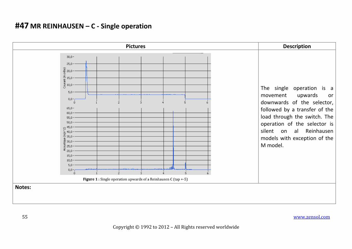
#47 MR REINHAUSEN – C - SINGLE OPERATION .............................................................................................................................................................................................................. 55

4 www.zensol.com
Copyright © 1992 to 2012 – All Rights reserved worldwide
#48 MR REINHAUSEN – C - TYPICAL SWITCHING ............................................................................................................................................................................................................. 56
#49 MR REINHAUSEN – D - WEAKENED SPRINGS ............................................................................................................................................................................................................ 57
#50 MR REINHAUSEN – D - TYPICAL SWITCHING ............................................................................................................................................................................................................ 58
#51 MR REINHAUSEN – E - TYPICAL SWITCHING ............................................................................................................................................................................................................. 59
#52 MR REINHAUSEN – F - TYPICAL SWITCHING ............................................................................................................................................................................................................. 60
#53 MR REINHAUSEN – G - TYPICAL SWITCHING ............................................................................................................................................................................................................ 61
#54 MR REINHAUSEN – VR - TYPICAL SWITCHING........................................................................................................................................................................................................... 62
#55 MR REINHAUSEN – VIII - EXPECTED SIGNATURE ....................................................................................................................................................................................................... 63
#56 MR REINHAUSEN – RMV II - TYPICAL SWITCHING .................................................................................................................................................................................................... 64
#57 ANY KIND OF TAP CHANGERS - LACK OF LUBRICATION ............................................................................................................................................................................................ 65
#58 ANY KIND OF TAP CHANGERS - POOR LUBRICATION ................................................................................................................................................................................................ 66
#59 UNKNOWN TAP CHANGER - ASYNCHRONISM .......................................................................................................................................................................................................... 67
#60 UNKNOWN TAP CHANGER - ARCING CONTACT ........................................................................................................................................................................................................ 68
#61 UNKNOWN TAP CHANGER - JOB QUALITY CONTROL ............................................................................................................................................................................................... 69
#62 OTHER APPLICATION – AIR COMPRESSOR OF 735KV BREAKERS .............................................................................................................................................................................. 70
#63 OTHER APPLICATION – COOPER VR 32 VOLTAGE REGULATOR WITH CL 5C CONTROL .............................................................................................................................................. 71
#64 OTHER APPLICATION – CHARACTERIZATION OF AN ARCING CONTACT .................................................................................................................................................................... 72
#65 OTHER APPLICATION – CIRCUIT BREAKERS (BAD ASSEMBLY) ................................................................................................................................................................................... 73
#66 OTHER APPLICATION – CIRCUIT BREAKERS (BAD ADJUSTMENT) .............................................................................................................................................................................. 74
5 www.zensol.com
Copyright © 1992 to 2012 – All Rights reserved worldwide
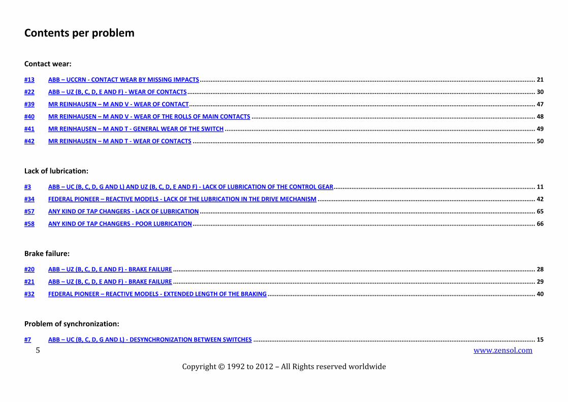
Contents per problem
Contact wear:
#13 ABB – UCCRN - CONTACT WEAR BY MISSING IMPACTS ............................................................................................................................................................................................ 21
#22 ABB – UZ (B, C, D, E AND F) - WEAR OF CONTACTS ................................................................................................................................................................................................... 30
#39 MR REINHAUSEN – M AND V - WEAR OF CONTACT .................................................................................................................................................................................................. 47
#40 MR REINHAUSEN – M AND V - WEAR OF THE ROLLS OF MAIN CONTACTS ............................................................................................................................................................... 48
#41 MR REINHAUSEN – M AND T - GENERAL WEAR OF THE SWITCH .............................................................................................................................................................................. 49
#42 MR REINHAUSEN – M AND T - WEAR OF CONTACTS ................................................................................................................................................................................................ 50
Lack of lubrication:
#3 ABB – UC (B, C, D, G AND L) AND UZ (B, C, D, E AND F) - LACK OF LUBRICATION OF THE CONTROL GEAR ................................................................................................................. 11
#34 FEDERAL PIONEER – REACTIVE MODELS - LACK OF THE LUBRICATION IN THE DRIVE MECHANISM .......................................................................................................................... 42
#57 ANY KIND OF TAP CHANGERS - LACK OF LUBRICATION ............................................................................................................................................................................................ 65
#58 ANY KIND OF TAP CHANGERS - POOR LUBRICATION ................................................................................................................................................................................................ 66
Brake failure:
#20 ABB – UZ (B, C, D, E AND F) - BRAKE FAILURE ........................................................................................................................................................................................................... 28
#21 ABB – UZ (B, C, D, E AND F) - BRAKE FAILURE ........................................................................................................................................................................................................... 29
#32 FEDERAL PIONEER – REACTIVE MODELS - EXTENDED LENGTH OF THE BRAKING ...................................................................................................................................................... 40
Problem of synchronization:
#7 ABB – UC (B, C, D, G AND L) - DESYNCHRONIZATION BETWEEN SWITCHES .............................................................................................................................................................. 15

6 www.zensol.com
Copyright © 1992 to 2012 – All Rights reserved worldwide
#10 ABB – UC (B, C, D, G AND L) - SWITCHING SYNCHRONIZATION ................................................................................................................................................................................. 18
#33 FEDERAL PIONEER – REACTIVE MODELS - DESYNCHRONIZATION OF THE SWITCHING ............................................................................................................................................. 41
#46 MR REINHAUSEN – C, D, E, F, G, M AND T - DESYNCHRONIZATION OF THE SWITCHING ........................................................................................................................................... 54
#59 UNKNOWN TAP CHANGER - ASYNCHRONISM .......................................................................................................................................................................................................... 67
Abnormal noise:
#36 FEDERAL PIONEER – REACTIVE MODELS - NOISE OF VERY HIGH AMPLITUDE SWITCHING ........................................................................................................................................ 44
#37 FEDERAL PIONEER – REACTIVE MODELS - NOISE OF VERY HIGH AMPLITUDE DURING THE OPERATION OF THE INVERTER ...................................................................................... 45
#38 FEDERAL PIONEER – REACTIVE MODELS - NOISE OF THE MECHANISM DURING ITS OPERATION .............................................................................................................................. 46
Problem of relay:
#6 ABB – UC (B, C, D, G AND L) AND UZ (B, C, D, E AND F) - FAULTY CONTROL RELAY ................................................................................................................................................... 14
#23 ABB – UZ (B, C, D, E AND F) FAULTY CONTROL RELAY ............................................................................................................................................................................................... 31
#35 FEDERAL PIONEER – REACTIVE MODELS - MOTOR STARTUP CONTACTOR ............................................................................................................................................................... 43
Arcing contact:
#25 ABB - UZCRN - ARCING CONTACT ............................................................................................................................................................................................................................. 33
#60 UNKNOWN TAP CHANGER - ARCING CONTACT ........................................................................................................................................................................................................ 68
Other problems:
#1 ABB – UC (B, C, D, G AND L) AND UZ (B, C, D, E AND F) - BRAID IMPROPERLY INSTALLED ........................................................................................................................................... 9
#2 ABB – UC (B, C, D, G AND L) AND UZ (B, C, D, E AND F) - BENDING OF THE MOVING MAIN CONTACT ARM .............................................................................................................. 10
#4 ABB – UC (B, C, D, G AND L) AND UZ (B, C, D, E AND F) - SLACK IN THE CONTROL ROD ............................................................................................................................................. 12

7 www.zensol.com
Copyright © 1992 to 2012 – All Rights reserved worldwide
#5 ABB – UC (B, C, D, G AND L) AND UZ (B, C, D, E AND F) - ADVANCED WEAR OF THE WHEEL SWITCH ........................................................................................................................ 13
#8 ABB – UC (B, C, D, G AND L) - ANOMALY IN THE VOLTAGE LIMITER DEVICE ............................................................................................................................................................. 16
#9 ABB – UC (B, C, D, G AND L) - TIME OF TRANSITION NOT PERCEPTIBLE .................................................................................................................................................................... 17
#11 ABB – UC (B, C, D, G AND L) - ALIGNING THE CONTACTS OF THE SELECTOR .............................................................................................................................................................. 19
#12 ABB – UC (B, C, D, G AND L) - ASYMMETRY OF SIGNATURES SWITCHING ................................................................................................................................................................. 20
#49 MR REINHAUSEN – D - WEAKENED SPRINGS ............................................................................................................................................................................................................ 57
#61 UNKNOWN TAP CHANGER - JOB QUALITY CONTROL ............................................................................................................................................................................................... 69
Typical signatures:
#14 ABB – UCB - TYPICAL SWITCHING ............................................................................................................................................................................................................................. 22
#15 ABB – UCC - TYPICAL SWITCHING ............................................................................................................................................................................................................................. 23
#16 ABB – UCD - TYPICAL SWITCHING ............................................................................................................................................................................................................................. 24
#17 ABB – UCG - TYPICAL SWITCHING............................................................................................................................................................................................................................. 25
#18 ABB – UCL - TYPICAL SWITCHING ............................................................................................................................................................................................................................. 26
#19 ABB – UC - EXPECTED SIGNATURE ............................................................................................................................................................................................................................ 27
#28 ABB – UZC, UZE AND UZF - TYPICAL SWITCHING ...................................................................................................................................................................................................... 36
#29 ABB – UZC, UZE AND UZF - TYPICAL SWITCHING ...................................................................................................................................................................................................... 37
#30 ABB – UZB - TYPICAL SWITCHING ............................................................................................................................................................................................................................. 38
#31 ABB UZ - EXPECTED SIGNATURE ............................................................................................................................................................................................................................... 39
#43 MR REINHAUSEN – M AND MS - TYPICAL SWITCHING .............................................................................................................................................................................................. 51
#48 MR REINHAUSEN – C - TYPICAL SWITCHING ............................................................................................................................................................................................................. 56
#50 MR REINHAUSEN – D - TYPICAL SWITCHING ............................................................................................................................................................................................................ 58
#51 MR REINHAUSEN – E - TYPICAL SWITCHING ............................................................................................................................................................................................................. 59
#52 MR REINHAUSEN – F - TYPICAL SWITCHING ............................................................................................................................................................................................................. 60
#53 MR REINHAUSEN – G - TYPICAL SWITCHING ............................................................................................................................................................................................................ 61

8 www.zensol.com
Copyright © 1992 to 2012 – All Rights reserved worldwide
#54 MR REINHAUSEN – VR - TYPICAL SWITCHING........................................................................................................................................................................................................... 62
#55 MR REINHAUSEN – VIII - EXPECTED SIGNATURE ....................................................................................................................................................................................................... 63
#56 MR REINHAUSEN – RMV II - TYPICAL SWITCHING .................................................................................................................................................................................................... 64
Tap changer configurations:
#24 ABB – UZ - TYPES OF TAPS ........................................................................................................................................................................................................................................ 32
#26 ABB – UZCRN - SINGLE OPERATION .......................................................................................................................................................................................................................... 34
#27 ABB – UZC, UZE AND UZF - MULTIPLE OPERATIONS ................................................................................................................................................................................................. 35
#44 MR REINHAUSEN – M - SINGLE OPERATION ............................................................................................................................................................................................................. 52
#45 MR REINHAUSEN – M - DUAL OPERATION ............................................................................................................................................................................................................... 53
#47 MR REINHAUSEN – C - SINGLE OPERATION .............................................................................................................................................................................................................. 55
Other applications:
#62 OTHER APPLICATION – AIR COMPRESSOR OF 735KV BREAKERS .............................................................................................................................................................................. 70
#63 OTHER APPLICATION – COOPER VR 32 VOLTAGE REGULATOR WITH CL 5C CONTROL .............................................................................................................................................. 71
#64 OTHER APPLICATION – CHARACTERIZATION OF AN ARCING CONTACT .................................................................................................................................................................... 72
#65 OTHER APPLICATION – CIRCUIT BREAKERS (BAD ASSEMBLY) ................................................................................................................................................................................... 73
#66 OTHER APPLICATION – CIRCUIT BREAKERS (BAD ADJUSTMENT) .............................................................................................................................................................................. 74

9 www.zensol.com
Copyright © 1992 to 2012 – All Rights reserved worldwide
#1 ABB – UC (B, C, D, G and L) and UZ (B, C, D, E and F) - Braid improperly installed
Pictures Description
The signature of a switch with a braid improperly installed (red trace) is easily distinguished from a normal switch (blue trace).
Notes: An improper installation of the braid may interfere with the operation of the mechanism and eventually cause its failure.

10 www.zensol.com
Copyright © 1992 to 2012 – All Rights reserved worldwide
#2 ABB – UC (B, C, D, G and L) and UZ (B, C, D, E and F) - Bending of the moving main contact arm
Pictures Description
As a result of repeated impacts during normal operations, the copper arm of the mobile contacts is bent and the minimum distance between mobile and fixed points of tungsten (0.5 mm) is no longer respected. This anomaly may cause local overheating due to the lower conductivity of tungsten. This anomaly is visible on the noise impact of arcing contacts. To discern the phenomenon of wear, you can note that the bending of the moving contact’s arm does not alter the sequence. (red trace) is contact arm bent. (blue trace) is after recovery of the arm.
Notes: Recovery or replacement of the main contact moving arm.

11 www.zensol.com
Copyright © 1992 to 2012 – All Rights reserved worldwide
#3 ABB – UC (B, C, D, G and L) and UZ (B, C, D, E and F) - Lack of lubrication of the control gear
Pictures Description
A lack of lubrication of the gear drive mechanism may affect the acoustic signature as shown in this example. This phenomenon is highlighted in particular in the signature of the lower frequencies.
Notes: Lubrication of the control gear.

12 www.zensol.com
Copyright © 1992 to 2012 – All Rights reserved worldwide
#4 ABB – UC (B, C, D, G and L) and UZ (B, C, D, E and F) - Slack in the control rod
Pictures Description
An important slack in the control rod can be shown in the signature of the motor current as shown above. When the motor starts with loose parts, the amplitude of the inrush current can be significantly reduced.
Notes: Tighten any loose components.

13 www.zensol.com
Copyright © 1992 to 2012 – All Rights reserved worldwide
#5 ABB – UC (B, C, D, G and L) and UZ (B, C, D, E and F) - Advanced wear of the wheel switch
Pictures Description
The slack caused by a very advanced wear of the wheel switch (the unit tested had accumulated above 400,000 operations) may cause the blocking of the mechanism, a loss of synchronization with the switch that can cause an arc across the terminals of the selector in the tank. This degradation is easily noticeable on the acoustic signature by a significant decrease of amplitudes with the wear. (red trace) is normal. (blue trace) is worn wheel switch.
Notes: Replacement of the wheel switch.

14 www.zensol.com
Copyright © 1992 to 2012 – All Rights reserved worldwide
#6 ABB – UC (B, C, D, G and L) and UZ (B, C, D, E and F) - Faulty control relay
Pictures Description
Anomalies of operation or of adjustment of control relays (upward, downward, maintenance, etc.) can often be observed by rapid fluctuations of the current. These anomalies are usually benign but still indicate a deterioration of the device which can ultimately lead to a refusal to operate; the operations are jerky or jumping to a position other than the set point. From the exploitation perspective, this behavior explains the reports of skipped taps.
Notes: Monitor this activity because it can lead to faulty tap switching.
15 www.zensol.com
Copyright © 1992 to 2012 – All Rights reserved worldwide
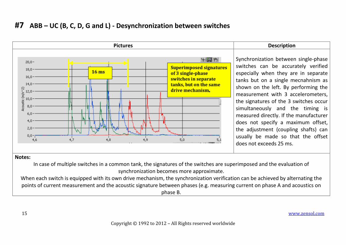
#7 ABB – UC (B, C, D, G and L) - Desynchronization between switches
Pictures Description
Synchronization between single-phase switches can be accurately verified especially when they are in separate tanks but on a single mecnahnism as shown on the left. By performing the measurement with 3 accelerometers, the signatures of the 3 switches occur simultaneously and the timing is measured directly. If the manufacturer does not specify a maximum offset, the adjustment (coupling shafts) can usually be made so that the offset does not exceeds 25 ms.
Notes: In case of multiple switches in a common tank, the signatures of the switches are superimposed and the evaluation of
synchronization becomes more approximate. When each switch is equipped with its own drive mechanism, the synchronization verification can be achieved by alternating the points of current measurement and the acoustic signature between phases (e.g. measuring current on phase A and acoustics on
phase B.
16 www.zensol.com
Copyright © 1992 to 2012 – All Rights reserved worldwide
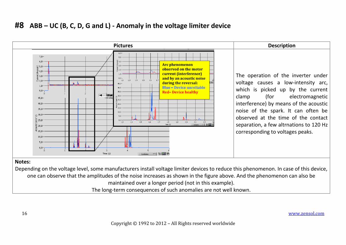
#8 ABB – UC (B, C, D, G and L) - Anomaly in the voltage limiter device
Pictures Description
The operation of the inverter under voltage causes a low-intensity arc, which is picked up by the current clamp (for electromagnetic interference) by means of the acoustic noise of the spark. It can often be observed at the time of the contact separation, a few altrnations to 120 Hz corresponding to voltages peaks.
Notes: Depending on the voltage level, some manufacturers install voltage limiter devices to reduce this phenomenon. In case of this device,
one can observe that the amplitudes of the noise increases as shown in the figure above. And the phenomenon can also be maintained over a longer period (not in this example).
The long-term consequences of such anomalies are not well known.

17 www.zensol.com
Copyright © 1992 to 2012 – All Rights reserved worldwide
#9 ABB – UC (B, C, D, G and L) - Time of transition not perceptible
Pictures Description
When the transition time is barely perceptible by a visual examination of the acoustic signature, the most likely causes are: -Misalignement of the mechanism (pass-through bolts) -Wear of the mechanism -Wear of the driving ring These anomalies are followed by an assymetry between even and odd operations. Contacts badly worn may also complicate the identification of the 3rd pic, but without causing an assymetry.
Notes:

18 www.zensol.com
Copyright © 1992 to 2012 – All Rights reserved worldwide
#10 ABB – UC (B, C, D, G and L) - Switching synchronization
Pictures Description
Following repairs, or adjustments in the driving mechanism, it is possible that the switching is out of synchronization. In these models, this anomaly can be demonstrated by comparing the upward and downward operations.
Notes: In order to correct the adjustment, we must rebuild the shaft coupling at the output of the control box.

19 www.zensol.com
Copyright © 1992 to 2012 – All Rights reserved worldwide
#11 ABB – UC (B, C, D, G and L) - Aligning the contacts of the selector
Pictures Description
A misalignment of the selector contacts can cause abnormal noise during its operation. For a model with inverter (or pre-selector) that noise will be observed in the two operations corresponding to the same tap as shown on the left. In this example, there is a noise at the departure of the taps 5 and 13 only, which corresponds to the same fixed contact.
Notes: For single-phase models, this noise can be confused with a normal arc noise when the test is performed under voltage. These arc
noises can be observed both at departure and arrival of the selector. The amplitude is usually a little higher at the departure of the selector when the movement removes the turns of regulation and vice versa for the arrival. For these models, the misalignment of
contacts can be observed only if the test is performed disconnected from voltage.

20 www.zensol.com
Copyright © 1992 to 2012 – All Rights reserved worldwide
#12 ABB – UC (B, C, D, G and L) - Asymmetry of signatures switching
Pictures Description
To check the symmetry of the switch you must graphically superimpose the signature of an even operation to an odd one. The probable causes of this asymmetry are: -The excessive wear of the driving wheel of the switch -A bad adjustment of the switch (adjustment screw – pass through bolts) -An uneven wear of contacts between the even and odd sides.
Notes: Adjustments to correct the situation.

21 www.zensol.com
Copyright © 1992 to 2012 – All Rights reserved worldwide
#13 ABB – UCCRN - Contact wear by missing impacts
Pictures Description
The closing of the main contacts becomes very weak with the wear of contacts. Contact wear is confirmed by opening up the ABB UCCRN tap changer and replacing the arcing contacts, as highlighted by the traces.
Notes: The loss of material caused by the wear of the driving contacts, for inertial effect, a variation in the sequence and a reduction of the
impact noise of the main arc contacts. Trending of the suspected contacts is necessary to know the speed of the degradation.

22 www.zensol.com
Copyright © 1992 to 2012 – All Rights reserved worldwide
#14 ABB – UCB - Typical switching
Pictures Description
Notes:

23 www.zensol.com
Copyright © 1992 to 2012 – All Rights reserved worldwide
#15 ABB – UCC - Typical switching
Pictures Description
Notes:

24 www.zensol.com
Copyright © 1992 to 2012 – All Rights reserved worldwide
#16 ABB – UCD - Typical switching
Pictures Description
Notes:

25 www.zensol.com
Copyright © 1992 to 2012 – All Rights reserved worldwide
#17 ABB – UCG - Typical switching
Pictures Description
Notes:

26 www.zensol.com
Copyright © 1992 to 2012 – All Rights reserved worldwide
#18 ABB – UCL - Typical switching
Pictures Description
Notes:

27 www.zensol.com
Copyright © 1992 to 2012 – All Rights reserved worldwide
#19 ABB – UC - Expected signature
Pictures Description
Notes:

28 www.zensol.com
Copyright © 1992 to 2012 – All Rights reserved worldwide
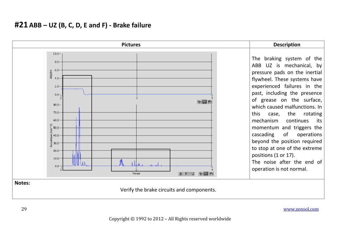
#20 ABB – UZ (B, C, D, E and F) - Brake failure
Pictures Description
The braking system of the ABB UZ is mechanical, by pressure pads on the inertial flywheel. These systems have experienced failures in the past, including the presence of grease on the surface, which caused malfunctions. In this case, the rotating mechanism continues its momentum and triggers the cascading of operations beyond the position required to stop at one of the extreme positions (1 or 17). The noise after the end of operation is not normal.
Notes: Verify the brake circuits and components.
29 www.zensol.com
Copyright © 1992 to 2012 – All Rights reserved worldwide
#21 ABB – UZ (B, C, D, E and F) - Brake failure
Pictures Description
The braking system of the ABB UZ is mechanical, by pressure pads on the inertial flywheel. These systems have experienced failures in the past, including the presence of grease on the surface, which caused malfunctions. In this case, the rotating mechanism continues its momentum and triggers the cascading of operations beyond the position required to stop at one of the extreme positions (1 or 17). The noise after the end of operation is not normal.
Notes: Verify the brake circuits and components.

30 www.zensol.com
Copyright © 1992 to 2012 – All Rights reserved worldwide
#22 ABB – UZ (B, C, D, E and F) - Wear of contacts
Pictures Description
Wear of the switch contacts appears on the acoustic signatures by a gap between the amplitudes of the traces of the High Frequency and the Low Frequency.
Notes: Trending of the suspected contacts is necessary to know the speed of the degradation.

31 www.zensol.com
Copyright © 1992 to 2012 – All Rights reserved worldwide
#23 ABB – UZ (B, C, D, E and F) Faulty control relay
Pictures Description
It is to note that sometimes with multiple operations there are important current fluctuations. These phenomena are due to a malfunction of the control relay. Usually a minor problem that can be tuned either by adjusting or replacing the defective relay.
Notes:

32 www.zensol.com
Copyright © 1992 to 2012 – All Rights reserved worldwide
#24 ABB – UZ - Types of taps
Pictures Description
The figure shows the setup of the fixed contacts of an ABB UZ operating with 17 taps with an inverter. As seen, there is a representation of two types of contacts, either as: contacts bridges and single contacts. There are so many types of switching, depending of the type of departure and arrival contact: -single contact to a contact bridge -contact bridge to a single contact -switching over the same contact bridge -contact bridge to a contact bridge -switching over the same contact bridge with an operation of the inverter -single contact to a single contact.
Notes: Each type of switching has a distinct signature since the mechanical mechanisms are themselves distinctive.

33 www.zensol.com
Copyright © 1992 to 2012 – All Rights reserved worldwide
#25 ABB - UZCRN - Arcing contact
Pictures Description
SUPERPOSITION OF
HIGH AND LOW FREQUENCIES
Notes:

34 www.zensol.com
Copyright © 1992 to 2012 – All Rights reserved worldwide
#26 ABB – UZCRN - Single operation
Pictures Description
The single operation is an upward or a downward movement of the selector, followed by a transfer of the load through the switch.
Notes:

35 www.zensol.com
Copyright © 1992 to 2012 – All Rights reserved worldwide
#27 ABB – UZC, UZE and UZF - Multiple operations
Pictures Description
Tap Changers of models ABB UZC, UZE and UZF have two different taps and several types of switching. When a moving contact must pass through several intermediate positions before reaching the next tap, the operation is called “multiple operations”. Multiple operations include triple and quadruple operations.
Notes: For example, when a moving contact is switched from tap 8 to tap 9, the switch passes through the intermediate positions 9A and 9B.
This operation is a triple operation and is expressed by multiple switching (x3) on the acoustic signature, as shown on the picture above.

36 www.zensol.com
Copyright © 1992 to 2012 – All Rights reserved worldwide
#28 ABB – UZC, UZE and UZF - Typical switching
Pictures Description
Notes:

37 www.zensol.com
Copyright © 1992 to 2012 – All Rights reserved worldwide
#29 ABB – UZC, UZE and UZF - Typical switching
Pictures Description
Notes:

38 www.zensol.com
Copyright © 1992 to 2012 – All Rights reserved worldwide
#30 ABB – UZB - Typical switching
Pictures Description
The ABB UZB has a configuration of 17 fixed positions. This allows the operation without a pre-selector or an inverter for the usual settings of our network. This eliminates multiple switching operations.
Notes: The ABB UZB is different from the other ABB UZ models due to the signatures of non-symmetrical upward and downward operations.

39 www.zensol.com
Copyright © 1992 to 2012 – All Rights reserved worldwide
#31 ABB UZ - Expected signature
Pictures Description
The normal switching operation of the ABB UZ model occurs close to the end of the motor current.
Notes:

40 www.zensol.com
Copyright © 1992 to 2012 – All Rights reserved worldwide
#32 FEDERAL PIONEER – REACTIVE MODELS - Extended length of the braking
Pictures Description
The trace of the current contains an extended braking. Dynamic brake is applied for an abnormally long time.
Notes: Adjust and repair the braking system.

41 www.zensol.com
Copyright © 1992 to 2012 – All Rights reserved worldwide
#33 FEDERAL PIONEER – REACTIVE MODELS - Desynchronization of the switching
Pictures Description
The switching occurs too early/late. It happens after the end of the motor current during the braking or much too early in the operation.
Notes: Synchronize the switching.
42 www.zensol.com
Copyright © 1992 to 2012 – All Rights reserved worldwide
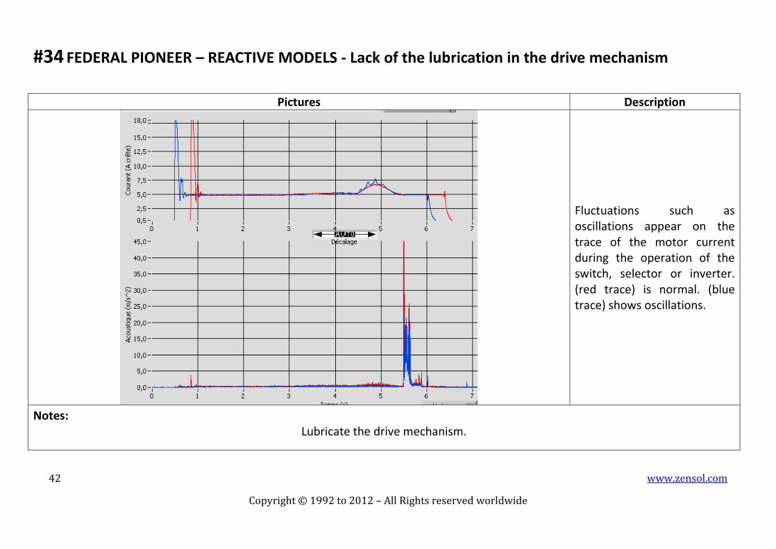
#34 FEDERAL PIONEER – REACTIVE MODELS - Lack of the lubrication in the drive mechanism
Pictures Description
Fluctuations such as oscillations appear on the trace of the motor current during the operation of the switch, selector or inverter. (red trace) is normal. (blue trace) shows oscillations.
Notes: Lubricate the drive mechanism.
43 www.zensol.com
Copyright © 1992 to 2012 – All Rights reserved worldwide
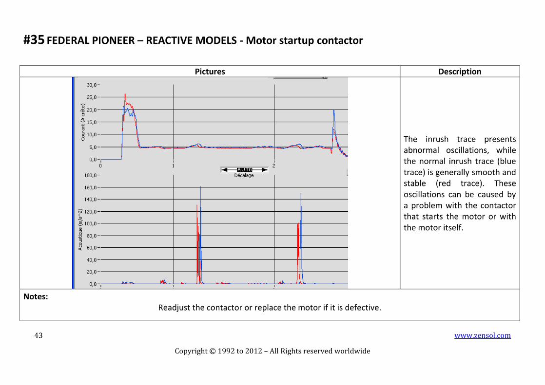
#35 FEDERAL PIONEER – REACTIVE MODELS - Motor startup contactor
Pictures Description
The inrush trace presents abnormal oscillations, while the normal inrush trace (blue trace) is generally smooth and stable (red trace). These oscillations can be caused by a problem with the contactor that starts the motor or with the motor itself.
Notes: Readjust the contactor or replace the motor if it is defective.

44 www.zensol.com
Copyright © 1992 to 2012 – All Rights reserved worldwide
#36 FEDERAL PIONEER – REACTIVE MODELS - Noise of very high amplitude switching
Pictures Description
The switching shows a noise with very high amplitude compared to normal switching, and compared with other noises on the same switching. This may be due to a problem of the transition of the spring, a problem with the switch mechanism or another cause.
Notes: Identify the cause of the problem and repair, by readjustment of the mechanism, changing the much worn parts or the springs.
45 www.zensol.com
Copyright © 1992 to 2012 – All Rights reserved worldwide
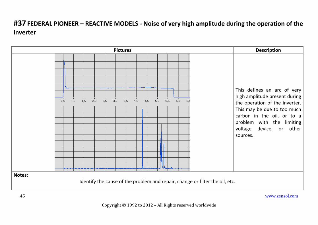
#37 FEDERAL PIONEER – REACTIVE MODELS - Noise of very high amplitude during the operation of the
inverter
Pictures Description
This defines an arc of very high amplitude present during the operation of the inverter. This may be due to too much carbon in the oil, or to a problem with the limiting voltage device, or other sources.
Notes: Identify the cause of the problem and repair, change or filter the oil, etc.

46 www.zensol.com
Copyright © 1992 to 2012 – All Rights reserved worldwide
#38 FEDERAL PIONEER – REACTIVE MODELS - Noise of the mechanism during its operation
Pictures Description
We notice a noise of the mechanism during its operation. The oscillations are present throughout all the trace of the High Frequency. A lack of lubrication of the drive mechanism or an advanced wear of the drive mechanism is present.
Notes: Correct the situation by lubricating or replacing worn parts or observe the OLTC periodically to monitor the problem at hand.

47 www.zensol.com
Copyright © 1992 to 2012 – All Rights reserved worldwide
#39 MR REINHAUSEN – M and V - Wear of contact
Pictures Description
!
The wear of contacts is seen as gaps between low and high frequency envelopes. A new mechanism will show similar envelopes while one of the envelopes becomes dominant as the wear increases.
Notes: Trending of the suspected contacts is necessary to know the speed of the degradation.

48 www.zensol.com
Copyright © 1992 to 2012 – All Rights reserved worldwide
#40 MR REINHAUSEN – M and V - Wear of the rolls of main contacts
Pictures Description
The rolls of the main contacts on a type D-0466 mechanism can wear off and show flats and streaks as above. Such type of wear can cause variations in the resistance measurements. The change of the cross is easily perceptible on the signatures of low-frequencies, Red curve is before repairs and blue is after repairs.
Notes: Replacement of the faulty hardware.

49 www.zensol.com
Copyright © 1992 to 2012 – All Rights reserved worldwide
#41 MR REINHAUSEN – M and T - General wear of the switch
Pictures Description
In addition to the wear of contacts, gaps between frequency bands are also indicative of the general wear of the switch. This example illustrates a case of extreme wear of a type M mechanism.
Notes:

50 www.zensol.com
Copyright © 1992 to 2012 – All Rights reserved worldwide
#42 MR REINHAUSEN – M and T - Wear of contacts
Pictures Description
The wear of contacts on types M and T, are seen as gaps between low and high frequency envelopes.
Notes: A new mechanism will show similar envelopes while the low frequency envelope becomes dominant as the wear increases.

51 www.zensol.com
Copyright © 1992 to 2012 – All Rights reserved worldwide
#43 MR REINHAUSEN – M and MS - Typical switching
Pictures Description
Notes:

52 www.zensol.com
Copyright © 1992 to 2012 – All Rights reserved worldwide
#44 MR REINHAUSEN – M - Single operation
Pictures Description
The selector of the type M tap changer is very noisy, as seen on the signature.
Notes:

53 www.zensol.com
Copyright © 1992 to 2012 – All Rights reserved worldwide
#45 MR REINHAUSEN – M - Dual operation
Pictures Description
The tap changer can access a second range of positions through the inverter. During the operation of the inverter, two switch operations are performed one after another, as shown on the acoustic signature below.
Notes: Again, the operation of the selector is silent on all models except the M type.

54 www.zensol.com
Copyright © 1992 to 2012 – All Rights reserved worldwide
#46 MR REINHAUSEN – C, D, E, F, G, M and T - Desynchronization of the switching
Pictures Description
A desynchronization may result from a poor adjustment, or following an inspection of a poor reinsertion. In extreme cases, the switching is so misadjusted that it may not happen in the current operation but during the subsequent operation, which may cause a delay of taps between two devices in parallel. Red curve is normal, blue curve is bad.
Notes: Adjustments to correct the situation.
55 www.zensol.com
Copyright © 1992 to 2012 – All Rights reserved worldwide
#47 MR REINHAUSEN – C - Single operation
Pictures Description
The single operation is a movement upwards or downwards of the selector, followed by a transfer of the load through the switch. The operation of the selector is silent on al Reinhausen models with exception of the M model.
Notes:

56 www.zensol.com
Copyright © 1992 to 2012 – All Rights reserved worldwide
#48 MR REINHAUSEN – C - Typical switching
Pictures Description
Notes:

57 www.zensol.com
Copyright © 1992 to 2012 – All Rights reserved worldwide
#49 MR REINHAUSEN – D - Weakened springs
Pictures Description
The weakening of a type D is expressed by a decrease in high frequency envelopes as shown in this example.
Notes:

58 www.zensol.com
Copyright © 1992 to 2012 – All Rights reserved worldwide
#50 MR REINHAUSEN – D - Typical switching
Pictures Description
The Reinhausen type D can have three different types of switches, namely: -LU D0466 -LU D20000 -LU D21000
Notes:

59 www.zensol.com
Copyright © 1992 to 2012 – All Rights reserved worldwide
#51 MR REINHAUSEN – E - Typical switching
Pictures Description
Notes:

60 www.zensol.com
Copyright © 1992 to 2012 – All Rights reserved worldwide
#52 MR REINHAUSEN – F - Typical switching
Pictures Description
Notes:

61 www.zensol.com
Copyright © 1992 to 2012 – All Rights reserved worldwide
#53 MR REINHAUSEN – G - Typical switching
Pictures Description
Notes:

62 www.zensol.com
Copyright © 1992 to 2012 – All Rights reserved worldwide
#54 MR REINHAUSEN – VR - Typical switching
Pictures Description
Notes:

63 www.zensol.com
Copyright © 1992 to 2012 – All Rights reserved worldwide
#55 MR REINHAUSEN – VIII - Expected signature
Pictures Description
Notes:

64 www.zensol.com
Copyright © 1992 to 2012 – All Rights reserved worldwide
#56 MR REINHAUSEN – RMV II - Typical switching
Pictures Description
Notes:

65 www.zensol.com
Copyright © 1992 to 2012 – All Rights reserved worldwide
#57 ANY KIND OF TAP CHANGERS - Lack of lubrication
Pictures Description
The trace of the motor current shows obvious fluctuations towards the end of the operation. There is a lack of lubrication of the drive mechanism. The lack of lubrication of the drive mechanism has a significant effect on the stress of the motor and sometimes causes a refusal to operate followed by the start of the motor protection.
Notes: To lubricate or replace worn parts or observe the tap changer periodically to monitor the problem at hand.

66 www.zensol.com
Copyright © 1992 to 2012 – All Rights reserved worldwide
#58 ANY KIND OF TAP CHANGERS - Poor lubrication
Pictures Description
An easy interpretation example is shown by the unusual shape of the motor current which increases at the end of the movement. Lack of lubrication leads to larger torques felt by the motor. As a result, the motor current can see sharp increases.
Notes: To lubricate or replace worn parts or observe the tap changer periodically to monitor the problem at hand.

67 www.zensol.com
Copyright © 1992 to 2012 – All Rights reserved worldwide
#59 Unknown Tap Changer - Asynchronism
Pictures Description
BEFORE REPAIR AFTER REPAIR
Certain types of signal analysis may be easily performed without a reference signature. The example shown demonstrates a switching operation signal delayed by 120 milliseconds after the end of the current envelope.
Notes: The repair was simply to uncouple the drive motor in order to adjust it so the switching occurs before the motor current drops.

68 www.zensol.com
Copyright © 1992 to 2012 – All Rights reserved worldwide
#60 Unknown Tap Changer - Arcing contact
Pictures Description
HIGH AND LOW FREQUENCY SUPERPOSITION OF
HIGH AND LOW FREQUENCIES
Notes:

69 www.zensol.com
Copyright © 1992 to 2012 – All Rights reserved worldwide
#61 Unknown Tap Changer - Job quality control
Pictures Description
Notes:

70 www.zensol.com
Copyright © 1992 to 2012 – All Rights reserved worldwide
#62 Other application – Air compressor of 735KV breakers
Pictures Description
The purposes of these tests were: -To verify the mounting of the compressor and make sure that it respects the manufacturer’s recommendations. -To find the origin of the random noise which is present before and after the #72 compressor mounting. With the results, we notice that the 60 ms cycle is divided in 4 regular impacts which refer to the mechanical motion. We also notice unpredictable impacts between 250G and 300G that would come from the radiator on the pipes on the #72 compressor.
Notes: Tests have been performed with accelerometers with a range of + or – 500G and AC current clamp.
The tests allows to see regular cycles in Amplitude, Time and Shape and also allow to check that there is no seating in the bearing; no wearing on the tree; no wearing on pistons.

71 www.zensol.com
Copyright © 1992 to 2012 – All Rights reserved worldwide
#63 Other application – COOPER VR 32 voltage regulator with CL 5C control
Pictures Description
Exploratory tests have been performed on a voltage regulator as a tap changer is used inside. Results are pretty similar to the ones we obtain when we do tests on transformer’s tap changers. We notice that the impact amplitude is quite low. It would be interesting to use a more precise accelerometer with a + or – 10G limitations instead of + or – 50Gs as we did.
It also would be interesting to do a test on a same kind of regulator in order to compare each other as we do on transformer’s tap changers.
Notes: Tests have been performed OFF-LINE with accelerometers with a limitation of + or – 50G and AC current clamp.
RAW DATA ENVELOPES

72 www.zensol.com
Copyright © 1992 to 2012 – All Rights reserved worldwide
#64 Other application – Characterization of an arcing contact
Pictures Description
Oil Oil Ceramic
The purpose is to show that an accelerometer can detect electric arcing through a tank full of oil or a ceramic tank. The current clamp is located on the primary of the arcing generator. We clearly see when the electric arcing appears and disappears.
Notes: Tests have been performed with accelerometers with a limitation of + or – 50G and an AC/DC current clamp.
The oil was extra dry as used for HV transformers.
73 www.zensol.com
Copyright © 1992 to 2012 – All Rights reserved worldwide
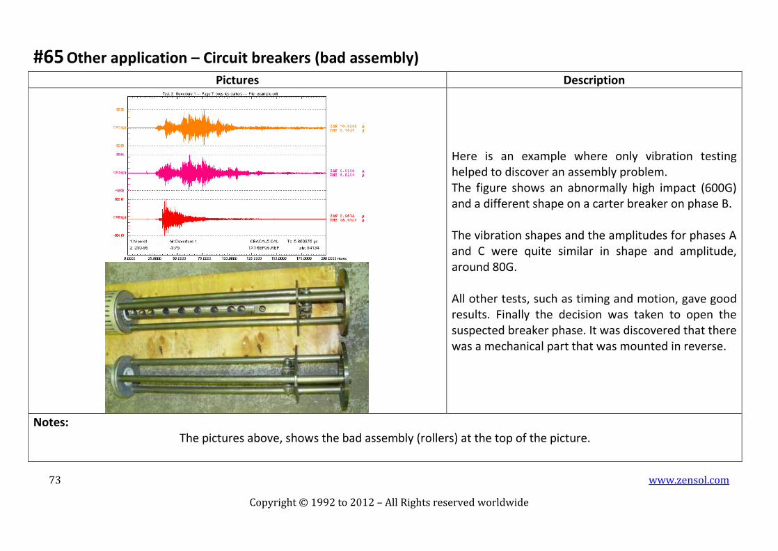
#65 Other application – Circuit breakers (bad assembly)
Pictures Description
Here is an example where only vibration testing helped to discover an assembly problem. The figure shows an abnormally high impact (600G) and a different shape on a carter breaker on phase B. The vibration shapes and the amplitudes for phases A and C were quite similar in shape and amplitude, around 80G. All other tests, such as timing and motion, gave good results. Finally the decision was taken to open the suspected breaker phase. It was discovered that there was a mechanical part that was mounted in reverse.
Notes: The pictures above, shows the bad assembly (rollers) at the top of the picture.

74 www.zensol.com
Copyright © 1992 to 2012 – All Rights reserved worldwide
#66 Other application – Circuit breakers (bad adjustment)
Pictures Description
BEFORE REPAIR AFTER REPAIR
This example shows two cases where a bad adjustment has broken the casing of a breaker that has produced an explosion and the other has produced a SF6 alarm. These two cases have been detected thanks to vibration testing. The figure shows the high impacts around 1300G for the middle trace which is phase B, whereas phases A and C show amplitude around 500G.
Notes: We see after repair, similar shapes and amplitudes for all three phases. The pictures show impact marks inside the casing of phase B.