Embed Size (px)
Citation preview

Suitability of Superregenerative Nuclear Quadrupole Resonance
Detector
R. Cumby, N. Sullivan
Abstract:
Nuclear quadrupole resonance (NQR) results when quadrupolar nuclei are excited by an AC magnetic field at the NQR frequency, inducing transitions in quadrupole energy levels. The energy of the transition is proportional to the product of the nuclear quadrupole moment and the electric field gradient (EFG) at the site of the nucleus. Because EFGs are properties of their crystals, no external DC magnetic field is needed to detect resonance. A superregenerative detector was designed with hopes of being used in a laboratory setting for NQR. Unfortunately, the device proved too difficult to tune and too sensitive to be used in a general lab setting.
I. Introduction
Nuclear quadrupole resonance (NQR) results when quadrupolar nuclei are
excited by an AC magnetic field at the NQR frequency. As NQR is a material specific
property, no external DC magnetic field is needed to detect NQR spectra. Because of
this nuclear quadrupole resonance detection has a broad range of applications, from
bomb detection to the discovery of oil wells.1
NQR detection has been performed with a number of different devices which
irradiate a sample with an AC magnetic field at radio frequency (RF) and measure
the response in some way.2 One major tool that may be suitable for this is a
superregenerative receiver. Superregenerative receivers function by using an active
component such as a transistor to simulate a negative impedance and thus amplify a
signal across a tank circuit consisting of a capacitor and inductor in parallel.3,4,5
When the voltage across the tank reaches a certain cutoff, it must be “quenched” and
allowed to return to zero in order to receive a signal.3,4,5 This can be accomplished
by an external signal or by means of an internal signal such as a colpitt’s oscillator.3,6
A superregenerative device for NQR detection was developed earlier by Bruin and
Khunaysir.6 However, they believed their device to be more useful as a classroom
demonstration than as a laboratory tool.6 The purpose of the project was then to
develop a supperregnerative NQR detector to be used in a lab environment,
specifically to determine the resonances of Cl35 and Cl37 in DTN, an organic
quantum magnet. The detector design developed by this lab proved to be too
sensitive and difficult to tune to be of use for scientific purposes, and it has been
determined that significant improvements must be made in the design and use of
these receivers in order to get useful results from them in the future.
II. Methods
The design used was inspired by the receiver design of Ranmuthu and Bruin
and Khunaysir.6,7 The final design is shown in Fig 1.
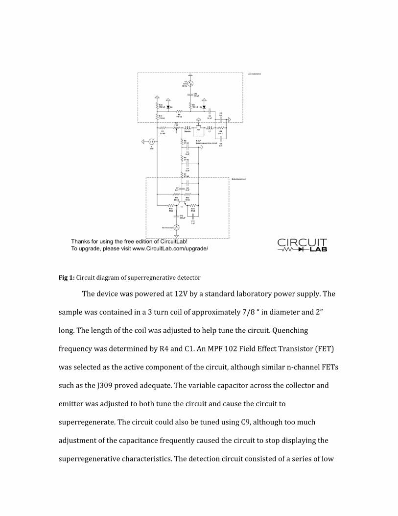
Fig 1: Circuit diagram of superregnerative detector
The device was powered at 12V by a standard laboratory power supply. The
sample was contained in a 3 turn coil of approximately 7/8 “ in diameter and 2”
long. The length of the coil was adjusted to help tune the circuit. Quenching
frequency was determined by R4 and C1. An MPF 102 Field Effect Transistor (FET)
was selected as the active component of the circuit, although similar n-‐channel FETs
such as the J309 proved adequate. The variable capacitor across the collector and
emitter was adjusted to both tune the circuit and cause the circuit to
superregenerate. The circuit could also be tuned using C9, although too much
adjustment of the capacitance frequently caused the circuit to stop displaying the
superregenerative characteristics. The detection circuit consisted of a series of low
pass filters connected to another FET, which acted as an amplifier. This was
connected to the oscilloscope by means of s short length of BNC cable. The AC
voltage from the transformer provided the AC magnetic field across the sample to
induce transition in the quadrupole energy levels.
In order to test a sample, the circuit was first tuned to the desired frequency.
Tuning was achieved by adjusting R2, C1, the length of the sample coil, and/or the
varicap across Q1. In order to test the frequency, a high-‐accuracy RF generator was
used. The RF frequency on the generator was moved until a response was viewed on
the screen of the oscilloscope. The RF generator was then switched off and the
sample placed in the coil. If a similar response on the screen of the oscilloscope was
viewed, then the NQR frequency was the same as the frequency on the RF generator.
Further confirmation that the observed effect was NQR could be observed by
bringing a magnet near the sample. If the “dip” on the screen disappeared, then the
frequency the receiver was tuned to was indeed the NQR frequency of the sample.
III. Results and Discussion
The detection circuit proves capable of picking up radio signals quite well.
Fig 2 displays the oscilloscope screen for the de-‐tuned circuit, while Fig 3 shows the
results of tuning the circuit to its resonant frequency. When the correct frequency is
selected, there is a noticeable drop off in the amount of noise in the signal. The
introduction of AM modulation from the frequency generator shows very clearly. Fig
4 shows the introduction of I kHz wave to the signal, While Fig. 5 shows the
introduction of a 400 Hz signal. In both cases, the modulation is visible and would
clearly be audible were one to attach a speaker to the output. The detector functions
as a very good radio receiver.
Fig 2. Output of de-‐tuned circuit on oscilloscope. Noise dominates the signal. The AC modulation is
only slightly visible.
Fig 3. Output of tuned circuit. AC modulation is now clearly visible and there is almost no noise in the
signal.
Fig 4. Output of tuned circuit with 1kHz modulation. Signal is now clearly modulates by the signal.
Due to good clarity and relatively little noise reception is quite good.
Fig 5. Output of tuned circuit with 400 Hz modulation. The AM modulation is clearly visible and has
almost no noise obscuring the signal.
The detector was unable to pick up NQR. The issue lies primarily in two
areas. First, the lack of ability to tune the circuit accurately over a broad range of
frequencies prevents one from adequately being able to dial in a very specific
frequency as is needed in NQR detection. While some change in frequency is
possible from adjusting either of the variable capacitors and the potentiometer, too
much adjustment leads to the circuit no longer superregnerating. Second, the circuit
is far too sensitive to external factors. The signal on the screen changes dramatically
when a person moves towards the receiver and detects a host of other objects in the
vicinity of the device. These signals are far greater than any signal that could be
received from the sample, and completely overwhelm the desired signal.
IV. Conclusion
The device proved to be unsuitable for the purposes intended. The issues of
tuning and sensitivity were too great for to be used to detect resonances that are too
complicated to be calculated from first principles alone. In order to improve the
design of the detector a better way of isolating the sample and the circuit must be
made to accurately tune to a broader range of frequencies. It is possible that
isolating the sample in some kind of box or shielding might be able to solve the
sensitivity issue, although the issue of tuning might not be as easy to solve.
However, the positive attributes of this device means that it may be a helpful tool in
the future if its problems are addressed.
Acknowledgement
Lab and materials provided by University of Florida. This work was
supported by the UF Material Physics REU Program through NSF grant DMR-‐
1156737. Much help was given by Allen Majewski.
References
1 A Garroway Nav. Rsch. Lab. (2003)
2 Taken from the lecture notes of N. Sullivan
3 E Insam, Electronics World (2002)
4 C Kitchin, AARL handbook (1998)
5 F. Xavier Moncunill-‐Geniz, P. Pala-‐Schonwalder, C. Dehollain, N. Joehl, and M.
Declercq, IEEE Trans. Microw. Theory Techn. 55 6 (2007)
6 F. Bruin, and H. Khunaysir, Am. J Phys. 38 12 (1970)

7 N. Ranmuthu, qsl.net (1999)