Embed Size (px)
Citation preview
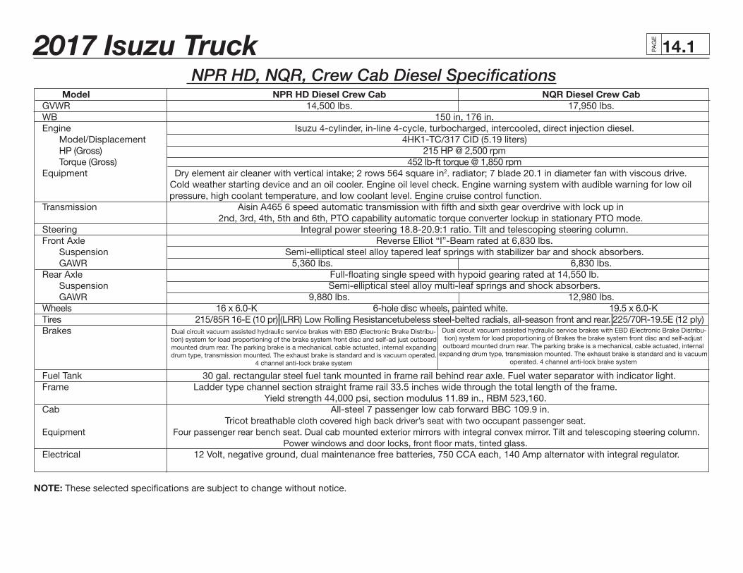
2017 Isuzu Truck PAG
E
.114
NPR HD, NQR, Crew Cab Diesel Specifications Model NPR HD Diesel Crew Cab NQR Diesel Crew Cab GVWR 14,500 lbs. 17,950 lbs. WB 150 in, 176 in. Engine Isuzu 4-cylinder, in-line 4-cycle, turbocharged, intercooled, direct injection diesel. Model/Displacement 4HK1-TC/317 CID (5.19 liters) HP (Gross) 215 HP @ 2,500 rpm Torque (Gross) 452 lb-ft torque @ 1,850 rpm Equipment Dry element air cleaner with vertical intake; 2 rows 564 square in2. radiator; 7 blade 20.1 in diameter fan with viscous drive. Cold weather starting device and an oil cooler. Engine oil level check. Engine warning system with audible warning for low oil pressure, high coolant temperature, and low coolant level. Engine cruise control function. Transmission Aisin A465 6 speed automatic transmission with fifth and sixth gear overdrive with lock up in 2nd, 3rd, 4th, 5th and 6th, PTO capability automatic torque converter lockup in stationary PTO mode. Steering Integral power steering 18.8-20.9:1 ratio. Tilt and telescoping steering column. Front Axle Reverse Elliot “I”-Beam rated at 6,830 lbs. Suspension Semi-elliptical steel alloy tapered leaf springs with stabilizer bar and shock absorbers. GAWR 5,360 lbs. 6,830 lbs. Rear Axle Full-floating single speed with hypoid gearing rated at 14,550 lb. Suspension Semi-elliptical steel alloy multi-leaf springs and shock absorbers. GAWR 9,880 lbs. 12,980 lbs. Wheels 16 x 6.0-K 6-hole disc wheels, painted white. 19.5 x 6.0-K Tires 215/85R 16-E (10 pr) (LRR) Low Rolling Resistancetubeless steel-belted radials, all-season front and rear. 225/70R-19.5E (12 ply) Brakes
Fuel Tank 30 gal. rectangular steel fuel tank mounted in frame rail behind rear axle. Fuel water separator with indicator light. Frame Ladder type channel section straight frame rail 33.5 inches wide through the total length of the frame. Yield strength 44,000 psi, section modulus 11.89 in., RBM 523,160. Cab All-steel 7 passenger low cab forward BBC 109.9 in. Tricot breathable cloth covered high back driver’s seat with two occupant passenger seat. Equipment Four passenger rear bench seat. Dual cab mounted exterior mirrors with integral convex mirror. Tilt and telescoping steering column. Power windows and door locks, front floor mats, tinted glass. Electrical 12 Volt, negative ground, dual maintenance free batteries, 750 CCA each, 140 Amp alternator with integral regulator. NOTE: These selected specifications are subject to change without notice.
Dual circuit vacuum assisted hydraulic service brakes with EBD (Electronic Brake Distribu-tion) system for load proportioning of the brake system front disc and self-ad just outboard mounted drum rear. The parking brake is a mechanical, cable actuated, internal expanding drum type, transmission mounted. The exhaust brake is standard and is vacuum operated.
4 channel anti-lock brake system
Dual circuit vacuum assisted hydraulic service brakes with EBD (Electronic Brake Distribu-tion) system for load proportioning of Brakes the brake system front disc and self-adjust outboard mounted drum rear. The parking brake is a mechanical, cable actuated, internal
expanding drum type, transmission mounted. The exhaust brake is standard and is vacuum operated. 4 channel anti-lock brake system
2017 Isuzu Truck PAG
E
.214
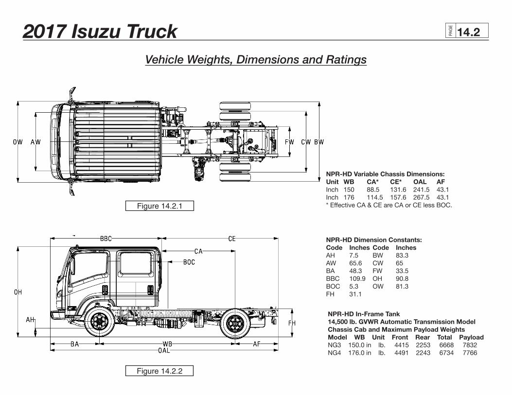
Vehicle Weights, Dimensions and Ratings
Figure 14.2.1
Figure 14.2.2
NPR-HD Variable Chassis Dimensions:Unit WB CA* CE* OAL AFInch 150 88.5 131.6 241.5 43.1Inch 176 114.5 157.6 267.5 43.1* Effective CA & CE are CA or CE less BOC.
NPR-HD Dimension Constants:Code Inches Code InchesAH 7.5 BW 83.3AW 65.6 CW 65BA 48.3 FW 33.5BBC 109.9 OH 90.8BOC 5.3 OW 81.3FH 31.1
NPR-HD In-Frame Tank 14,500 lb. GVWR Automatic Transmission Model Chassis Cab and Maximum Payload Weights Model WB Unit Front Rear Total Payload NG3 150.0 in lb. 4415 2253 6668 7832 NG4 176.0 in lb. 4491 2243 6734 7766
2017 Isuzu Truck PAG
E
.314
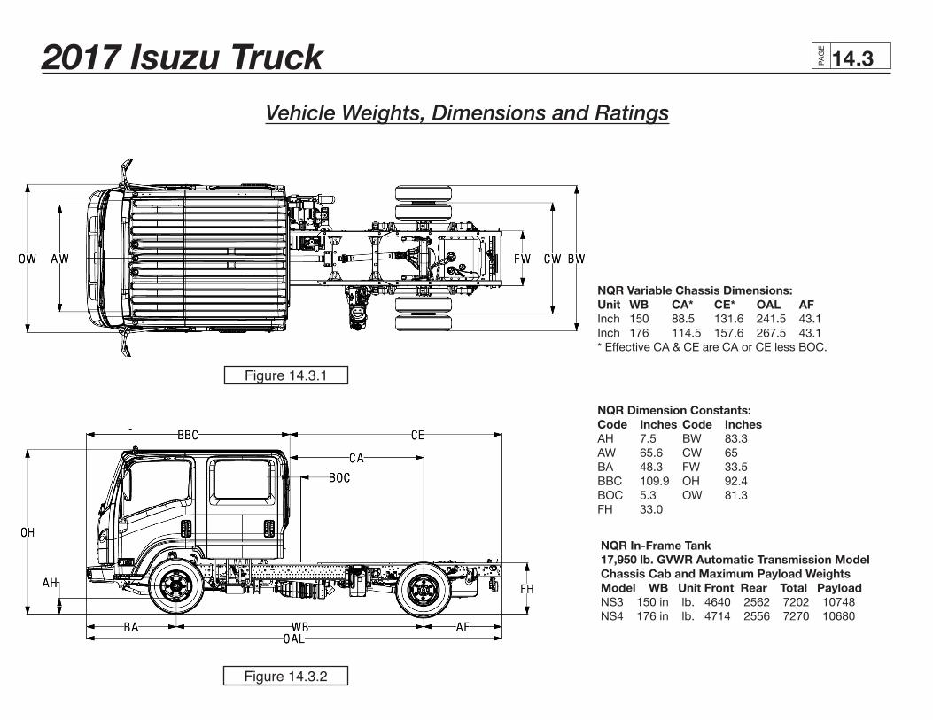
Vehicle Weights, Dimensions and Ratings
Figure 14.3.1
Figure 14.3.2
NQR Dimension Constants:Code Inches Code InchesAH 7.5 BW 83.3AW 65.6 CW 65BA 48.3 FW 33.5BBC 109.9 OH 92.4BOC 5.3 OW 81.3FH 33.0
NQR Variable Chassis Dimensions:Unit WB CA* CE* OAL AFInch 150 88.5 131.6 241.5 43.1Inch 176 114.5 157.6 267.5 43.1* Effective CA & CE are CA or CE less BOC.
NQR In-Frame Tank 17,950 lb. GVWR Automatic Transmission Model Chassis Cab and Maximum Payload Weights Model WB Unit Front Rear Total Payload NS3 150 in lb. 4640 2562 7202 10748 NS4 176 in lb. 4714 2556 7270 10680
2017 Isuzu Truck PAG
E
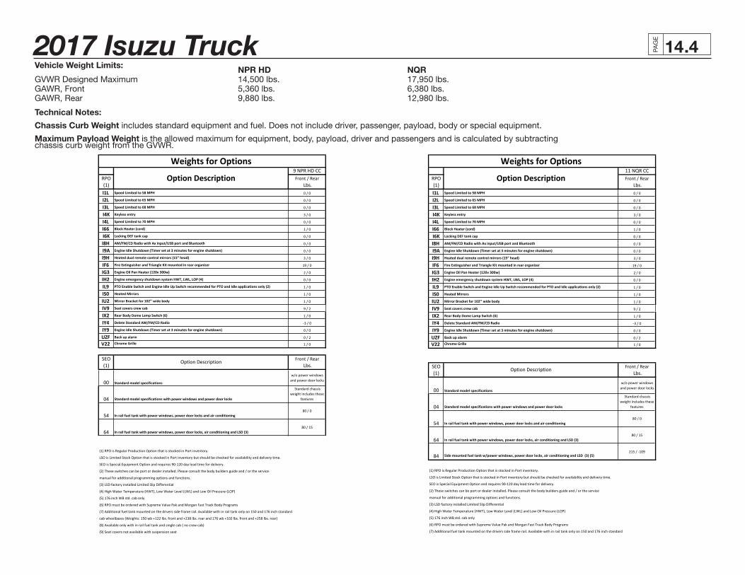
.414Vehicle Weight Limits: NPR HD NQRGVWR Designed Maximum 14,500 lbs. 17,950 lbs.GAWR, Front 5,360 lbs. 6,380 lbs.GAWR, Rear 9,880 lbs. 12,980 lbs.
Technical Notes:
Chassis Curb Weight includes standard equipment and fuel. Does not include driver, passenger, payload, body or special equipment.
Maximum Payload Weight is the allowed maximum for equipment, body, payload, driver and passengers and is calculated by subtractingchassis curb weight from the GVWR.
9 NPR HD CCRPO Front / Rear(1) Lbs.I1L Speed Limited to 58 MPH 0 / 0
I2L Speed Limited to 65 MPH 0 / 0
I3L Speed Limited to 68 MPH 0 / 0
I4K Keyless entry 3 / 0
I4L Speed Limited to 70 MPH 0 / 0
I66 Block Heater (cord) 1 / 0
I6K Locking DEF tank cap 0 / 0
I8H AM/FM/CD Radio with Ax input/USB port and Bluetooth 0 / 0
I9A Engine Idle Shutdown (Timer set at 3 minutes for engine shutdown) 0 / 0
I9H Heated dual remote control mirrors (15” head) 3 / 0
IF6 Fire Extinguisher and Triangle Kit mounted in rear organizer 19 / 0
IG3 Engine Oil Pan Heater (120v 300w) 2 / 0
IH2 Engine emergency shutdown system HWT, LWL, LOP (4) 0 / 0
IL9 PTO Enable Switch and Engine Idle Up Switch recommended for PTO and Idle applications only (2) 1 / 0
IS0 Heated Mirrors 1 / 0
IU2 Mirror Bracket for 102’’ wide body 1 / 0
IV9 Seat covers crew cab 9 / 2
IX2 Rear Body Dome Lamp Switch (6) 1 / 0
IY4 Delete Standard AM/FM/CD Radio -‐3 / 0
IY9 Engine Idle Shutdown (Timer set at 3 minutes for engine shutdown) 0 / 0
UZF Back up alarm 0 / 2
V22 Chrome Grille 1 / 0
SEO Front / Rear(1) Lbs.
00 Standard model specifications
w/o power windows and power door locks
04 Standard model specifications with power windows and power door locks
Standard chassis weight includes these
features
54 In rail fuel tank with power windows, power door locks and air conditioning80 / 0
64 In rail fuel tank with power windows, power door locks, air conditioning and LSD (3)80 / 15
(1) RPO is Regular Production Option that is stocked in Port inventory.
LSO is Limited Stock Option that is stocked in Port inventory but should be checked for availability and delivery time.
SEO is Special Equipment Option and requires 90-‐120 day lead time for delivery.
(2) These switches can be port or dealer installed. Please consult the body builders guide and / or the service
manual for additional programming options and functions.
(3) LSD factory installed Limited Slip Differential
(4) High Water Temperature (HWT), Low Water Level (LWL) and Low Oil Pressure (LOP)
(5) 176 inch WB std. cab only
(6) RPO must be ordered with Supreme Value Pak and Morgan Fast Track Body Programs
(7) Additional fuel tank mounted on the drivers side frame rail. Available with in rail tank only on 150 and 176 inch standard
cab wheelbases (Weights: 150 wb +122 lbs. front and +238 lbs. rear and 176 wb +102 lbs. front and +258 lbs. rear)
(8) Available only with in rail fuel tank and single cab ( no crew cab)
(9) Seat covers not available with suspension seat
Option Description
Weights for Options
Option Description11 NQR CC
RPO Front / Rear(1) Lbs.I1L Speed Limited to 58 MPH 0 / 0
I2L Speed Limited to 65 MPH 0 / 0
I3L Speed Limited to 68 MPH 0 / 0
I4K Keyless entry 3 / 0
I4L Speed Limited to 70 MPH 0 / 0
I66 Block Heater (cord) 1 / 0
I6K Locking DEF tank cap 0 / 0
I8H AM/FM/CD Radio with Ax input/USB port and Bluetooth 0 / 0
I9A Engine Idle Shutdown (Timer set at 3 minutes for engine shutdown) 0 / 0
I9H Heated dual remote control mirrors (15” head) 3 / 0
IF6 Fire Extinguisher and Triangle Kit mounted in rear organizer 19 / 0
IG3 Engine Oil Pan Heater (120v 300w) 2 / 0
IH2 Engine emergency shutdown system HWT, LWL, LOP (4) 0 / 0
IL9 PTO Enable Switch and Engine Idle Up Switch recommended for PTO and Idle applications only (2) 1 / 0
IS0 Heated Mirrors 1 / 0
IU2 Mirror Bracket for 102’’ wide body 1 / 0
IV9 Seat covers crew cab 9 / 2
IX2 Rear Body Dome Lamp Switch (6) 1 / 0
IY4 Delete Standard AM/FM/CD Radio -‐3 / 0
IY9 Engine Idle Shutdown (Timer set at 3 minutes for engine shutdown) 0 / 0
UZF Back up alarm 0 / 2
V22 Chrome Grille 1 / 0
SEO Front / Rear(1) Lbs.
00 Standard model specifications
w/o power windows and power door locks
04 Standard model specifications with power windows and power door locks
Standard chassis weight includes these
features
54 In rail fuel tank with power windows, power door locks and air conditioning80 / 0
64 In rail fuel tank with power windows, power door locks, air conditioning and LSD (3)80 / 15
84 Side mounted fuel tank w/power windows, power door locks, air conditioning and LSD (3) (5)215 / -‐109
(1) RPO is Regular Production Option that is stocked in Port inventory.
LSO is Limited Stock Option that is stocked in Port inventory but should be checked for availability and delivery time.
SEO is Special Equipment Option and requires 90-‐120 day lead time for delivery.
(2) These switches can be port or dealer installed. Please consult the body builders guide and / or the service
manual for additional programming options and functions.
(3) LSD factory installed Limited Slip Differential
(4) High Water Temperature (HWT), Low Water Level (LWL) and Low Oil Pressure (LOP)
(5) 176 inch WB std. cab only
(6) RPO must be ordered with Supreme Value Pak and Morgan Fast Track Body Programs
(7) Additional fuel tank mounted on the drivers side frame rail. Available with in rail tank only on 150 and 176 inch standard
cab wheelbases (Weights: 150 wb +122 lbs. front and +238 lbs. rear and 176 wb +102 lbs. front and +258 lbs. rear)
(8) Available only with in rail fuel tank and single cab ( no crew cab)
(9) Seat covers not available with suspension seat
Weights for Options
Option Description
Option Description
2017 Isuzu Truck PAG
E
.514
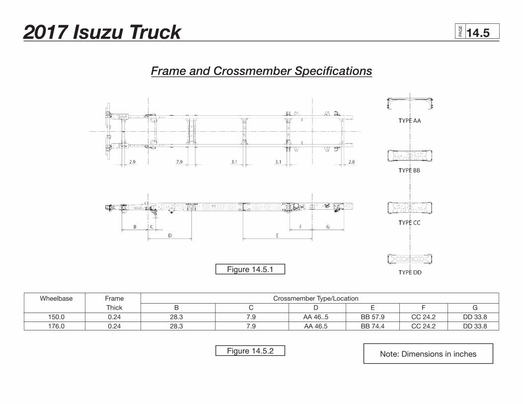
Wheelbase Frame Crossmember Type/Location Thick B C D E F G 150.0 0.24 28.3 7.9 AA 46..5 BB 57.9 CC 24.2 DD 33.8 176.0 0.24 28.3 7.9 AA 46.5 BB 74.4 CC 24.2 DD 33.8
Frame and Crossmember Specifications
Note: Dimensions in inches
Figure 14.5.1
Figure 14.5.2
2017 Isuzu Truck PAG
E
.614
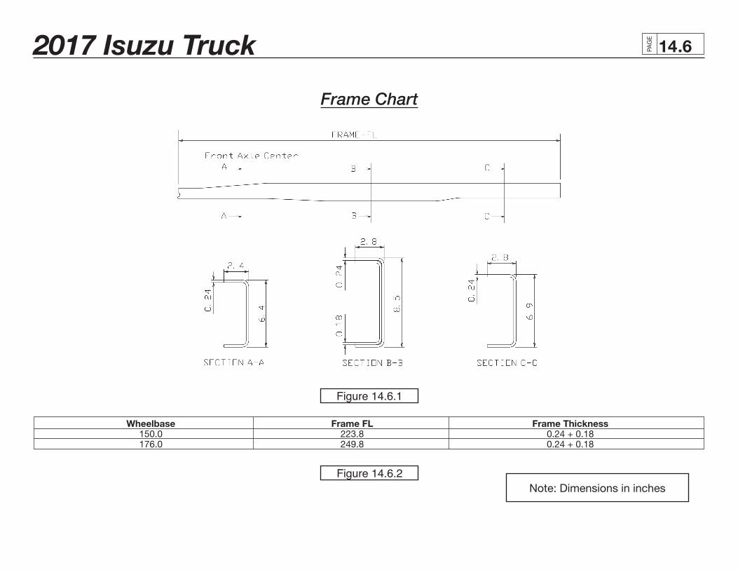
Frame Chart
Wheelbase Frame FL Frame Thickness 150.0 223.8 0.24 + 0.18 176.0 249.8 0.24 + 0.18
Note: Dimensions in inches
Figure 14.6.1
Figure 14.6.2
2017 Isuzu Truck PAG
E
.714
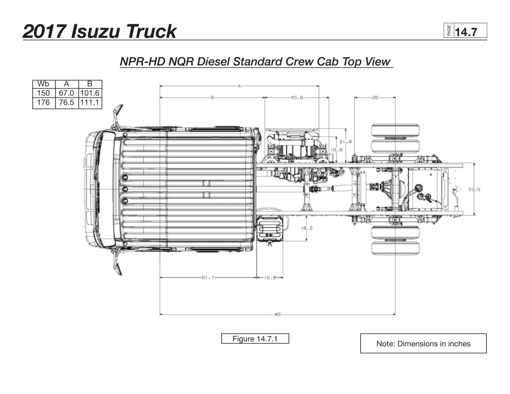
NPR-HD NQR Diesel Standard Crew Cab Top View
Note: Dimensions in inches
Wb A B 150 67.0 101.6 176 76.5 111.1
Figure 14.7.1
2017 Isuzu Truck PAG
E
.814
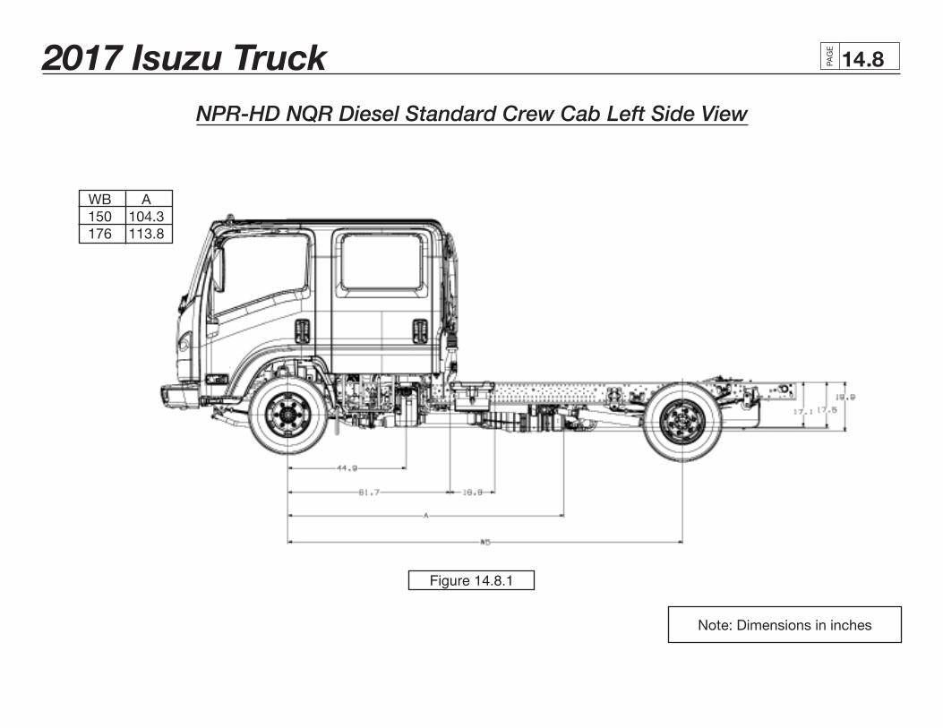
NPR-HD NQR Diesel Standard Crew Cab Left Side View
Note: Dimensions in inches
WB A 150 104.3 176 113.8
Figure 14.8.1
2017 Isuzu Truck PAG
E
.914
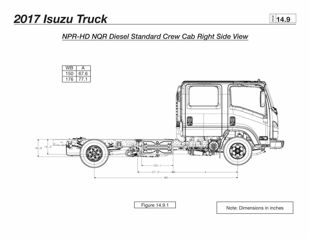
NPR-HD NQR Diesel Standard Crew Cab Right Side View
Note: Dimensions in inches
WB A 150 67.6 176 77.1
Figure 14.9.1
2017 Isuzu Truck PAG
E
.1014
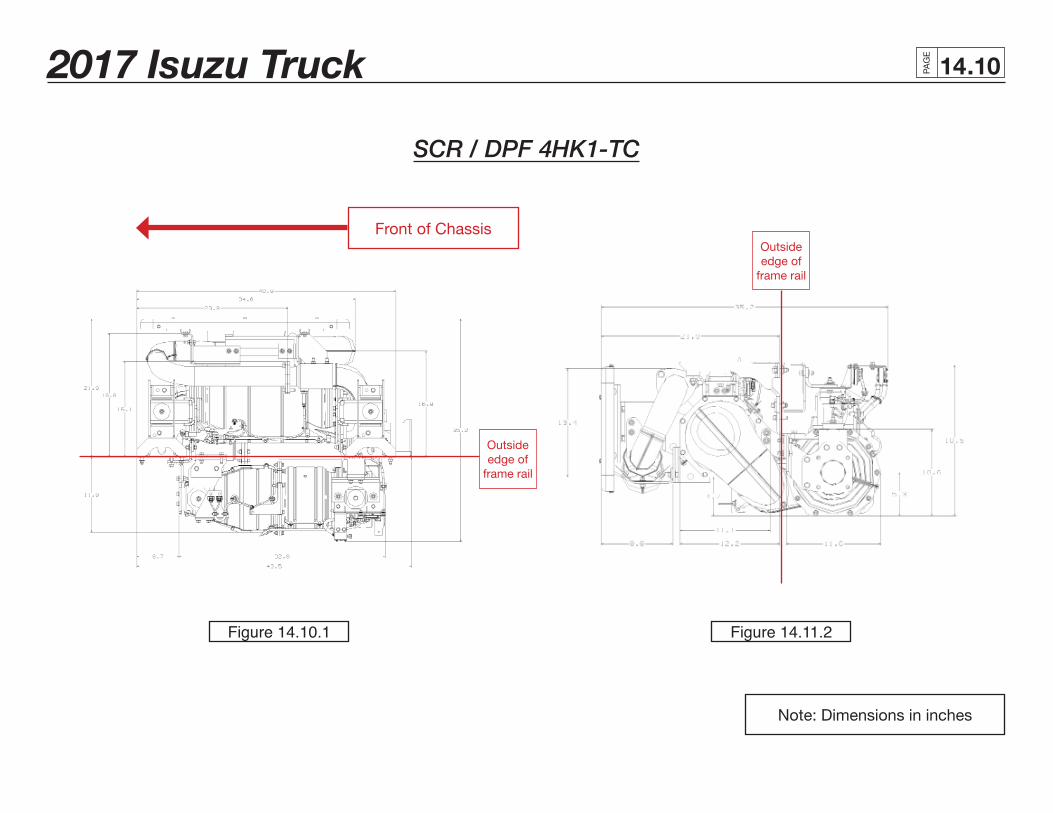
SCR / DPF 4HK1-TC
Note: Dimensions in inches
Front of Chassis
Outside edge of
frame rail
Outside edge of
frame rail
Figure 14.10.1 Figure 14.11.2
2017 Isuzu Truck PAG
E
.1114
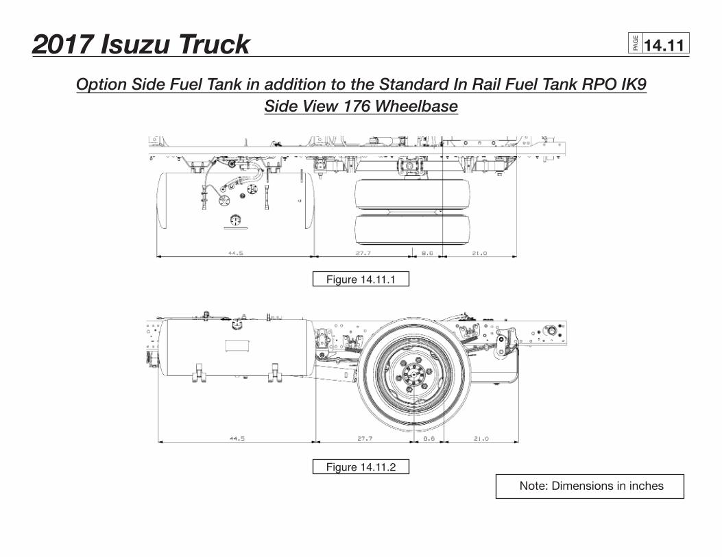
Option Side Fuel Tank in addition to the Standard In Rail Fuel Tank RPO IK9Side View 176 Wheelbase
Note: Dimensions in inches
Figure 14.11.1
Figure 14.11.2
2017 Isuzu Truck PAG
E
.1214
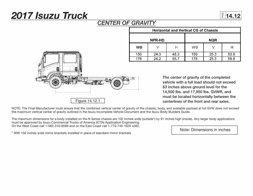
NOTE: The Final Manufacturer must ensure that the combined vertical center of gravity of the chassis, body, and available payload at full GVW does not exceed the maximum vertical center of gravity outlined in the Isuzu Incomplete Vehicle Document and the Isuzu Body Builders Guide.
The maximum dimensions for a body installed on the N Series chassis are 102 inches wide (outside*) by 91 inches high (inside). Any larger body applications must be approved by Isuzu Commercial Trucks of America (ICTA) Application Engineering. On the West Coast call 1-562-310-8599 and on the East Coast call 1-770-740-1620 x262. * With 102 inches wide mirror brackets installed in place of standard mirror brackets
The center of gravity of the completed vehicle with a full load should not exceed 63 inches above ground level for the 14,500 lbs. and 17,950 lbs. GVWR, and must be located horizontally between the centerlines of the front and rear axles.
CENTER OF GRAVITY
Note: Dimensions in inches
Figure 14.12.1
2017 Isuzu Truck PAG
E
.1314
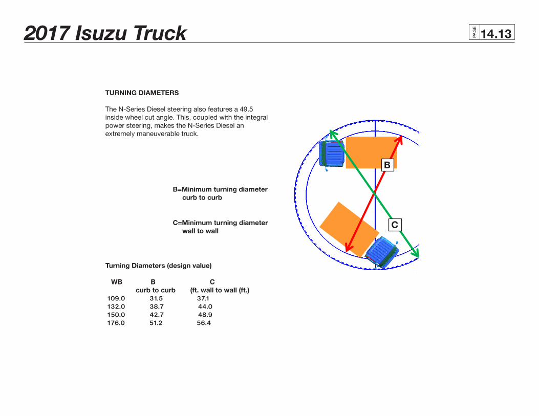
TURNING DIAMETERS
The N-Series Diesel steering also features a 49.5 inside wheel cut angle. This, coupled with the integral power steering, makes the N-Series Diesel an extremely maneuverable truck.
B=Minimum turning diameter curb to curb
C=Minimum turning diameter wall to wall
Turning Diameters (design value) WB B C curb to curb (ft. wall to wall (ft.) 109.0 31.5 37.1 132.0 38.7 44.0 150.0 42.7 48.9 176.0 51.2 56.4
A B
C
VN60 B
C
2017 Isuzu Truck PAG
E
.1414
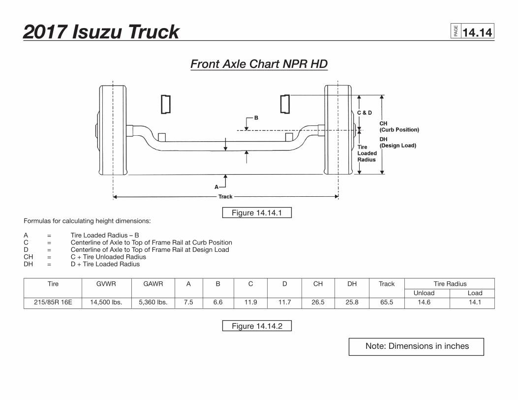
Front Axle Chart NPR HD
Formulas for calculating height dimensions:
A = Tire Loaded Radius – BC = Centerline of Axle to Top of Frame Rail at Curb PositionD = Centerline of Axle to Top of Frame Rail at Design LoadCH = C + Tire Unloaded RadiusDH = D + Tire Loaded Radius
Tire GVWR GAWR A B C D CH DH Track Tire Radius Unload Load 215/85R 16E 14,500 lbs. 5,360 lbs. 7.5 6.6 11.9 11.7 26.5 25.8 65.5 14.6 14.1
Note: Dimensions in inches
Figure 14.14.1
Figure 14.14.2
2017 Isuzu Truck PAG
E
.1514
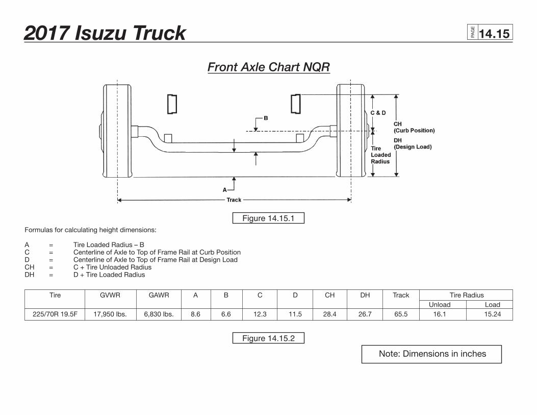
Front Axle Chart NQR
Formulas for calculating height dimensions:
A = Tire Loaded Radius – BC = Centerline of Axle to Top of Frame Rail at Curb PositionD = Centerline of Axle to Top of Frame Rail at Design LoadCH = C + Tire Unloaded RadiusDH = D + Tire Loaded Radius
Tire GVWR GAWR A B C D CH DH Track Tire Radius Unload Load 225/70R 19.5F 17,950 lbs. 6,830 lbs. 8.6 6.6 12.3 11.5 28.4 26.7 65.5 16.1 15.24
Note: Dimensions in inches
Figure 14.15.1
Figure 14.15.2
2017 Isuzu Truck PAG
E
.1614
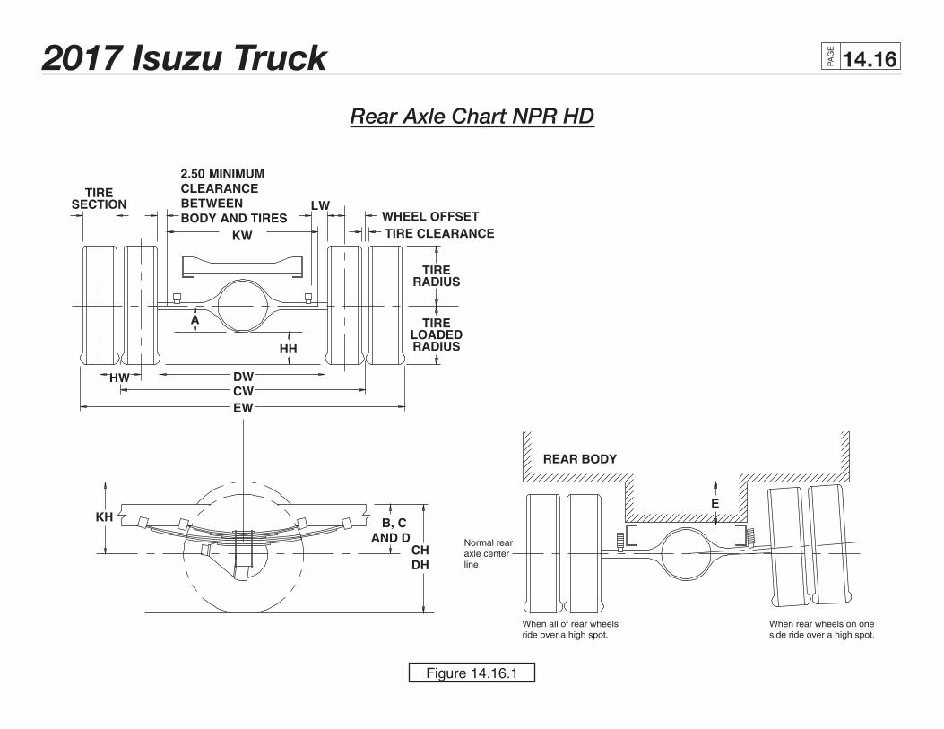
Rear Axle Chart NPR HD
Figure 14.16.1
2017 Isuzu Truck PAG
E
.1714
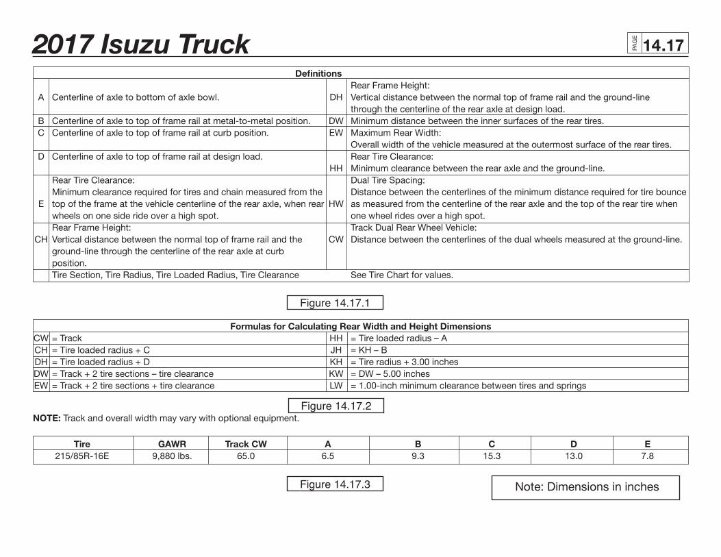
Definitions Rear Frame Height: A Centerline of axle to bottom of axle bowl. DH Vertical distance between the normal top of frame rail and the ground-line through the centerline of the rear axle at design load. B Centerline of axle to top of frame rail at metal-to-metal position. DW Minimum distance between the inner surfaces of the rear tires. C Centerline of axle to top of frame rail at curb position. EW Maximum Rear Width: Overall width of the vehicle measured at the outermost surface of the rear tires. D Centerline of axle to top of frame rail at design load. Rear Tire Clearance: HH Minimum clearance between the rear axle and the ground-line. Rear Tire Clearance: Dual Tire Spacing: Minimum clearance required for tires and chain measured from the Distance between the centerlines of the minimum distance required for tire bounce E top of the frame at the vehicle centerline of the rear axle, when rear HW as measured from the centerline of the rear axle and the top of the rear tire when wheels on one side ride over a high spot. one wheel rides over a high spot. Rear Frame Height: Track Dual Rear Wheel Vehicle: CH Vertical distance between the normal top of frame rail and the CW Distance between the centerlines of the dual wheels measured at the ground-line. ground-line through the centerline of the rear axle at curb position. Tire Section, Tire Radius, Tire Loaded Radius, Tire Clearance See Tire Chart for values.
Formulas for Calculating Rear Width and Height Dimensions CW = Track HH = Tire loaded radius – A CH = Tire loaded radius + C JH = KH – B DH = Tire loaded radius + D KH = Tire radius + 3.00 inches DW = Track + 2 tire sections – tire clearance KW = DW – 5.00 inches EW = Track + 2 tire sections + tire clearance LW = 1.00-inch minimum clearance between tires and springs
NOTE: Track and overall width may vary with optional equipment.
Tire GAWR Track CW A B C D E 215/85R-16E 9,880 lbs. 65.0 6.5 9.3 15.3 13.0 7.8
Note: Dimensions in inches
Figure 14.17.1
Figure 14.17.2
Figure 14.17.3

2017 Isuzu Truck PAG
E
.1814
Rear Axle Chart NQR
Figure 14.18.1
2017 Isuzu Truck PAG
E
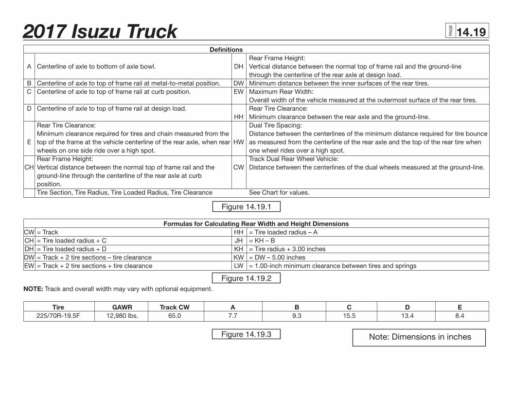
.1914 Definitions Rear Frame Height: A Centerline of axle to bottom of axle bowl. DH Vertical distance between the normal top of frame rail and the ground-line through the centerline of the rear axle at design load. B Centerline of axle to top of frame rail at metal-to-metal position. DW Minimum distance between the inner surfaces of the rear tires. C Centerline of axle to top of frame rail at curb position. EW Maximum Rear Width: Overall width of the vehicle measured at the outermost surface of the rear tires. D Centerline of axle to top of frame rail at design load. Rear Tire Clearance: HH Minimum clearance between the rear axle and the ground-line. Rear Tire Clearance: Dual Tire Spacing: Minimum clearance required for tires and chain measured from the Distance between the centerlines of the minimum distance required for tire bounce E top of the frame at the vehicle centerline of the rear axle, when rear HW as measured from the centerline of the rear axle and the top of the rear tire when wheels on one side ride over a high spot. one wheel rides over a high spot. Rear Frame Height: Track Dual Rear Wheel Vehicle: CH Vertical distance between the normal top of frame rail and the CW Distance between the centerlines of the dual wheels measured at the ground-line. ground-line through the centerline of the rear axle at curb position. Tire Section, Tire Radius, Tire Loaded Radius, Tire Clearance See Chart for values.
Formulas for Calculating Rear Width and Height Dimensions CW = Track HH = Tire loaded radius – A CH = Tire loaded radius + C JH = KH – B DH = Tire loaded radius + D KH = Tire radius + 3.00 inches DW = Track + 2 tire sections – tire clearance KW = DW – 5.00 inches EW = Track + 2 tire sections + tire clearance LW = 1.00-inch minimum clearance between tires and springs
NOTE: Track and overall width may vary with optional equipment.
Tire GAWR Track CW A B C D E 225/70R-19.5F 12,980 lbs. 65.0 7.7 9.3 15.5 13.4 8.4
Note: Dimensions in inches
Figure 14.19.1
Figure 14.19.2
Figure 14.19.3
2017 Isuzu Truck PAG
E
.2014
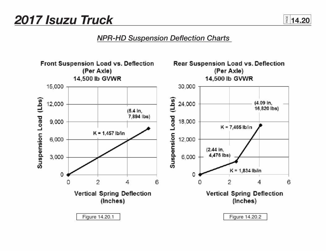
NPR-HD Suspension Deflection Charts
Figure 14.20.1 Figure 14.20.2
2017 Isuzu Truck PAG
E
.2114
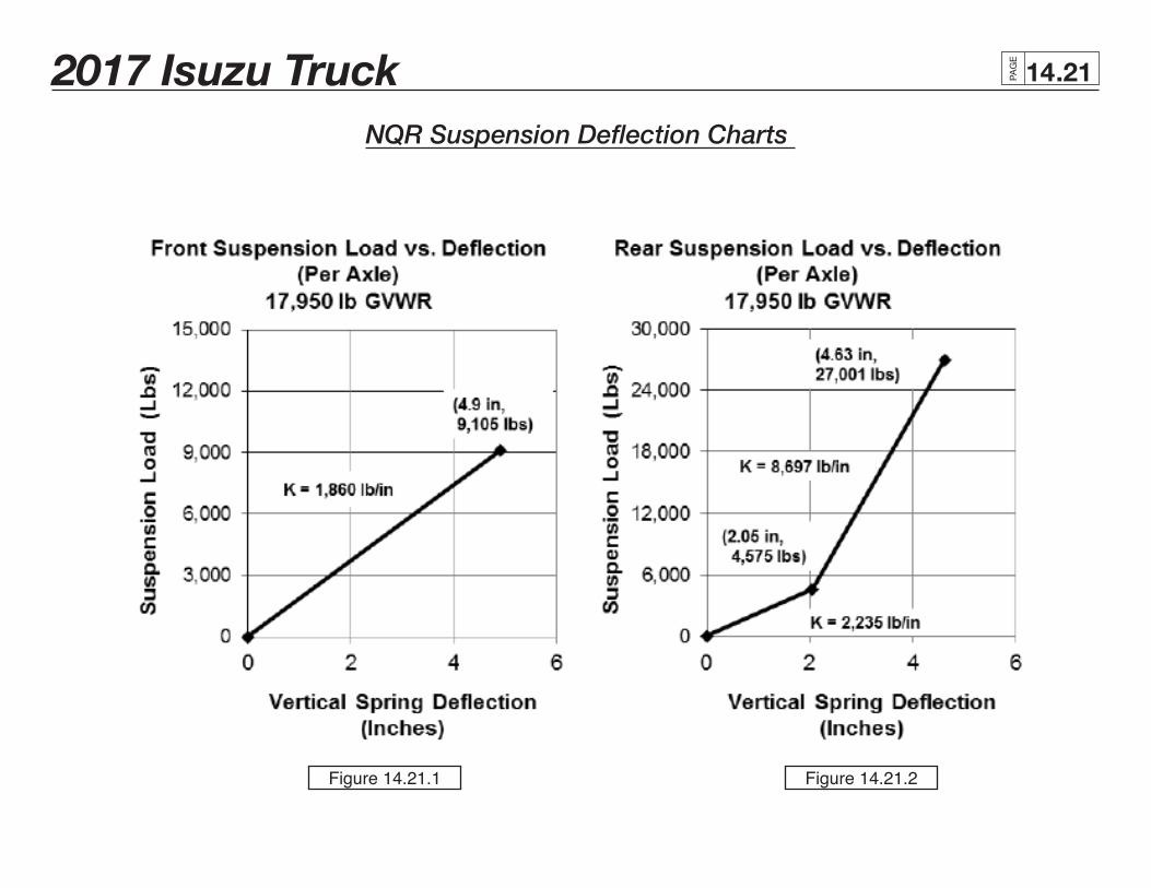
NQR Suspension Deflection Charts
Figure 14.21.1 Figure 14.21.2
2017 Isuzu Truck PAG
E
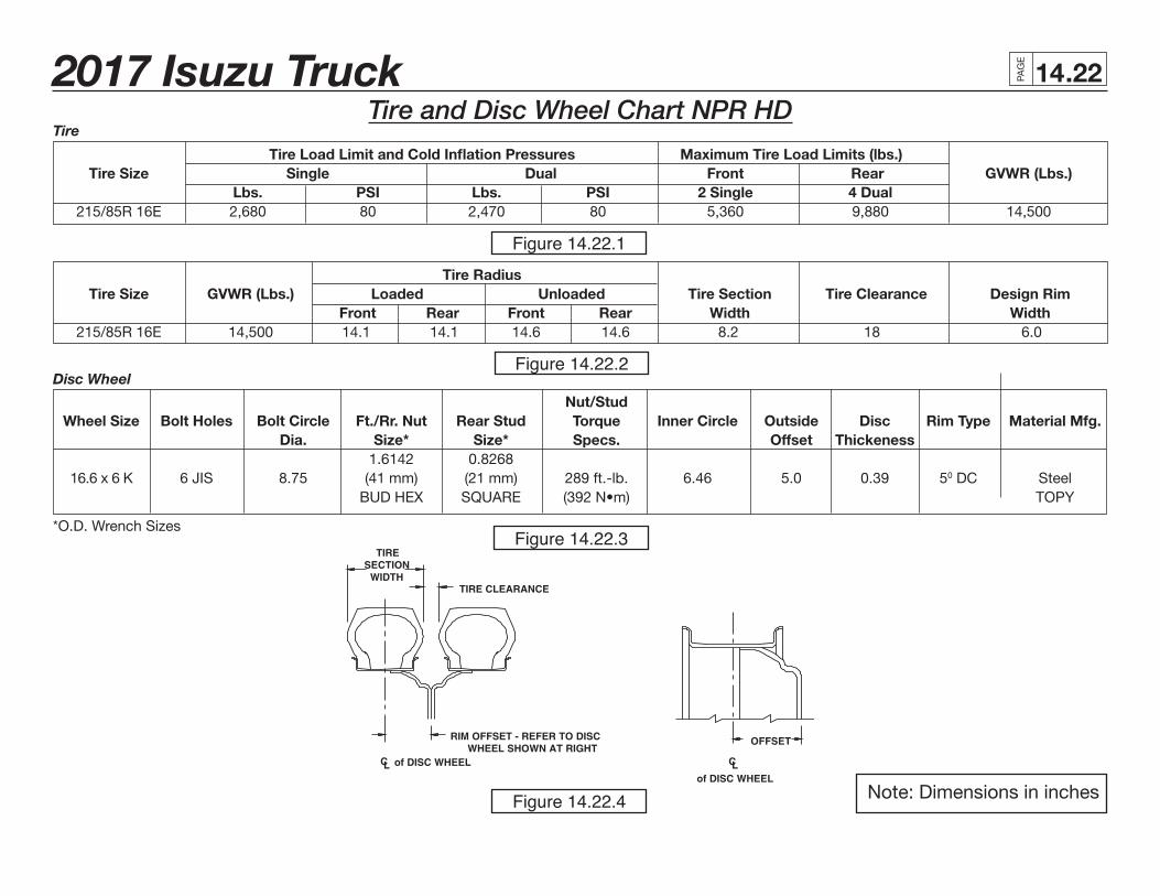
.2214Tire and Disc Wheel Chart NPR HD
Tire Load Limit and Cold Inflation Pressures Maximum Tire Load Limits (lbs.) Tire Size Single Dual Front Rear GVWR (Lbs.) Lbs. PSI Lbs. PSI 2 Single 4 Dual 215/85R 16E 2,680 80 2,470 80 5,360 9,880 14,500
Tire Radius Tire Size GVWR (Lbs.) Loaded Unloaded Tire Section Tire Clearance Design Rim Front Rear Front Rear Width Width 215/85R 16E 14,500 14.1 14.1 14.6 14.6 8.2 18 6.0
Nut/Stud Wheel Size Bolt Holes Bolt Circle Ft./Rr. Nut Rear Stud Torque Inner Circle Outside Disc Rim Type Material Mfg. Dia. Size* Size* Specs. Offset Thickeness 1.6142 0.8268 16.6 x 6 K 6 JIS 8.75 (41 mm) (21 mm) 289 ft.-lb. 6.46 5.0 0.39 50 DC Steel BUD HEX SQUARE (392 N•m) TOPY
Tire
Disc Wheel
*O.D. Wrench Sizes
Note: Dimensions in inches
Figure 14.22.1
Figure 14.22.2
Figure 14.22.3
Figure 14.22.4
2017 Isuzu Truck PAG
E
.23142015 Isuzu Truck PAG
E
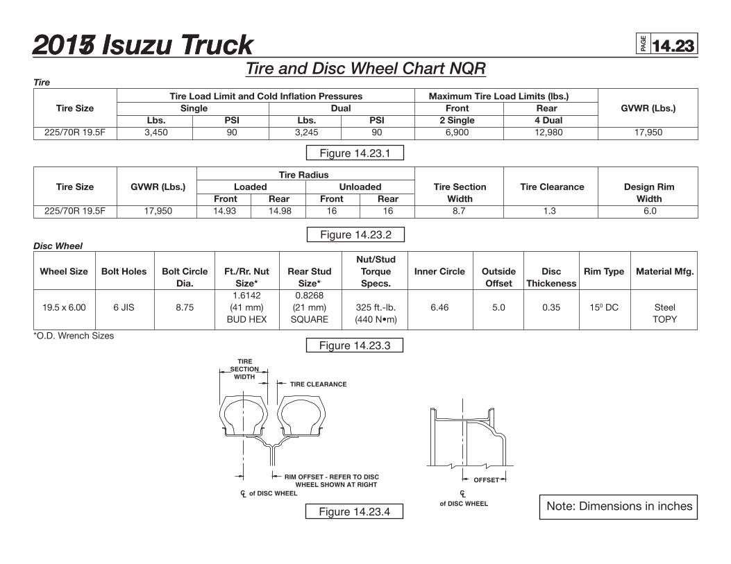
.2314Tire and Disc Wheel Chart NQR
Tire Load Limit and Cold Inflation Pressures Maximum Tire Load Limits (lbs.) Tire Size Single Dual Front Rear GVWR (Lbs.) Lbs. PSI Lbs. PSI 2 Single 4 Dual 225/70R 19.5F 3,450 90 3,245 90 6,900 12,980 17,950
Tire Radius Tire Size GVWR (Lbs.) Loaded Unloaded Tire Section Tire Clearance Design Rim Front Rear Front Rear Width Width 225/70R 19.5F 17,950 14.93 14.98 16 16 8.7 1.3 6.0
Nut/Stud Wheel Size Bolt Holes Bolt Circle Ft./Rr. Nut Rear Stud Torque Inner Circle Outside Disc Rim Type Material Mfg. Dia. Size* Size* Specs. Offset Thickeness 1.6142 0.8268 19.5 x 6.00 6 JIS 8.75 (41 mm) (21 mm) 325 ft.-lb. 6.46 5.0 0.35 150 DC Steel BUD HEX SQUARE (440 N•m) TOPY
Tire
Disc Wheel
*O.D. Wrench Sizes
Note: Dimensions in inches
Figure 14.23.1
Figure 14.23.2
Figure 14.23.3
Figure 14.23.4
2017 Isuzu Truck PAG
E
.24142015 Isuzu Truck PAG
E
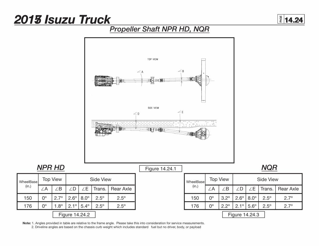
.2414Propeller Shaft NPR HD, NQR
NPR HD NQRFigure 14.24.1
Figure 14.24.2 Figure 14.24.3
WheelBase(in.)
WheelBase(in.)
Top View Top ViewSide View Side View
∠A ∠B ∠D ∠E Trans. Rear Axle
150 0º 2.7º 2.6º 8.0º 2.5º 2.5º
176 0º 1.8º 2.1º 5.4º 2.5º 2.5º
∠A ∠B ∠D ∠E Trans. Rear Axle
150 0º 3.2º 2.6º 8.0º 2.5º 2.7º
176 0º 2.2º 2.1º 5.6º 2.5º 2.7º
Note: 1. Angles provided in table are relative to the frame angle. Please take this into consideration for service measurements. 2. Driveline angles are based on the chassis curb weight which includes standard fuel but no driver, body, or payload
2017 Isuzu Truck PAG
E
.2514
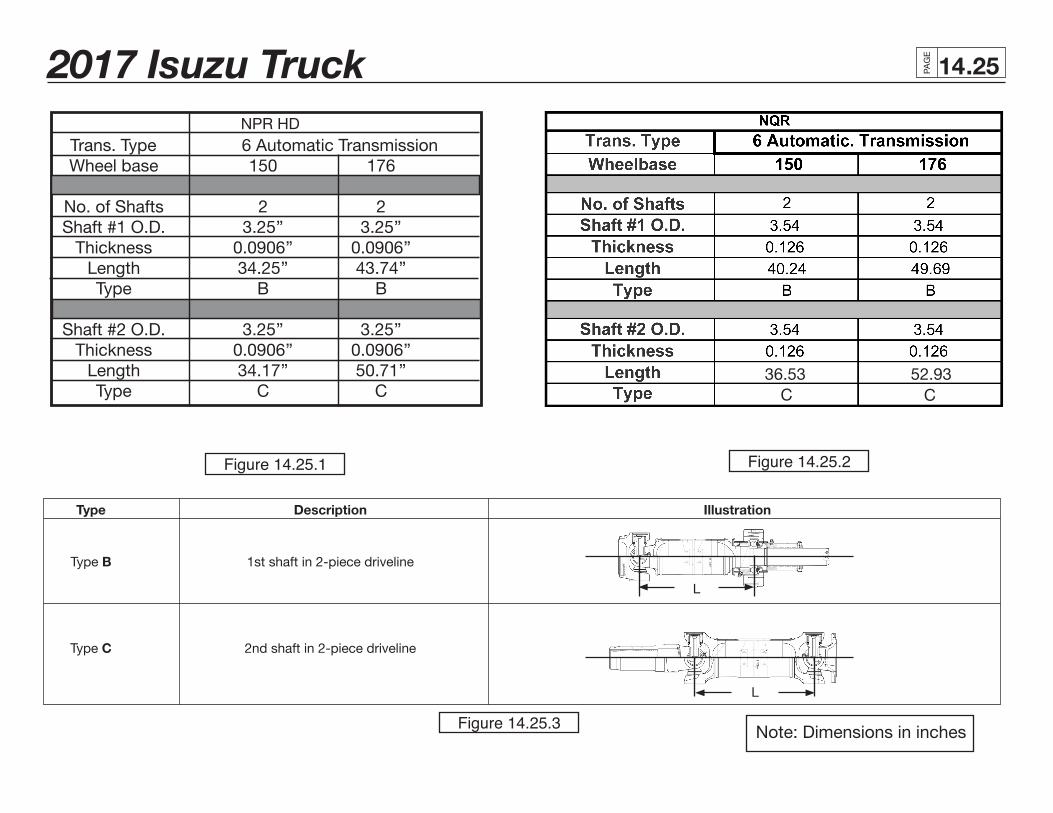
Note: Dimensions in inches
NPR HD Trans. Type 6 Automatic Transmission Wheel base 150 176
No. of Shafts 2 2 Shaft #1 O.D. 3.25’’ 3.25’’ Thickness 0.0906’’ 0.0906’’ Length 34.25’’ 43.74’’ Type B B Shaft #2 O.D. 3.25’’ 3.25’’ Thickness 0.0906’’ 0.0906’’ Length 34.17’’ 50.71’’ Type C C
Type Description Illustration
Type B 1st shaft in 2-piece driveline
Type C 2nd shaft in 2-piece driveline
L
L
Figure 14.25.1 Figure 14.25.2
Figure 14.25.3
36.53C C
52.93
2017 Isuzu Truck PAG
E
.2614
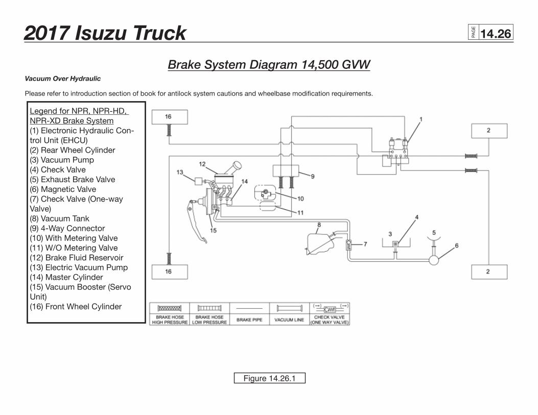
Vacuum Over Hydraulic
Please refer to introduction section of book for antilock system cautions and wheelbase modification requirements.
Brake System Diagram 14,500 GVW
Figure 14.26.1
Legend for NPR, NPR-HD, NPR-XD Brake System(1) Electronic Hydraulic Con-trol Unit (EHCU)(2) Rear Wheel Cylinder(3) Vacuum Pump(4) Check Valve(5) Exhaust Brake Valve(6) Magnetic Valve(7) Check Valve (One-way Valve)(8) Vacuum Tank(9) 4-Way Connector(10) With Metering Valve(11) W/O Metering Valve(12) Brake Fluid Reservoir(13) Electric Vacuum Pump(14) Master Cylinder(15) Vacuum Booster (Servo Unit)(16) Front Wheel Cylinder
2017 Isuzu Truck PAG
E
.2714
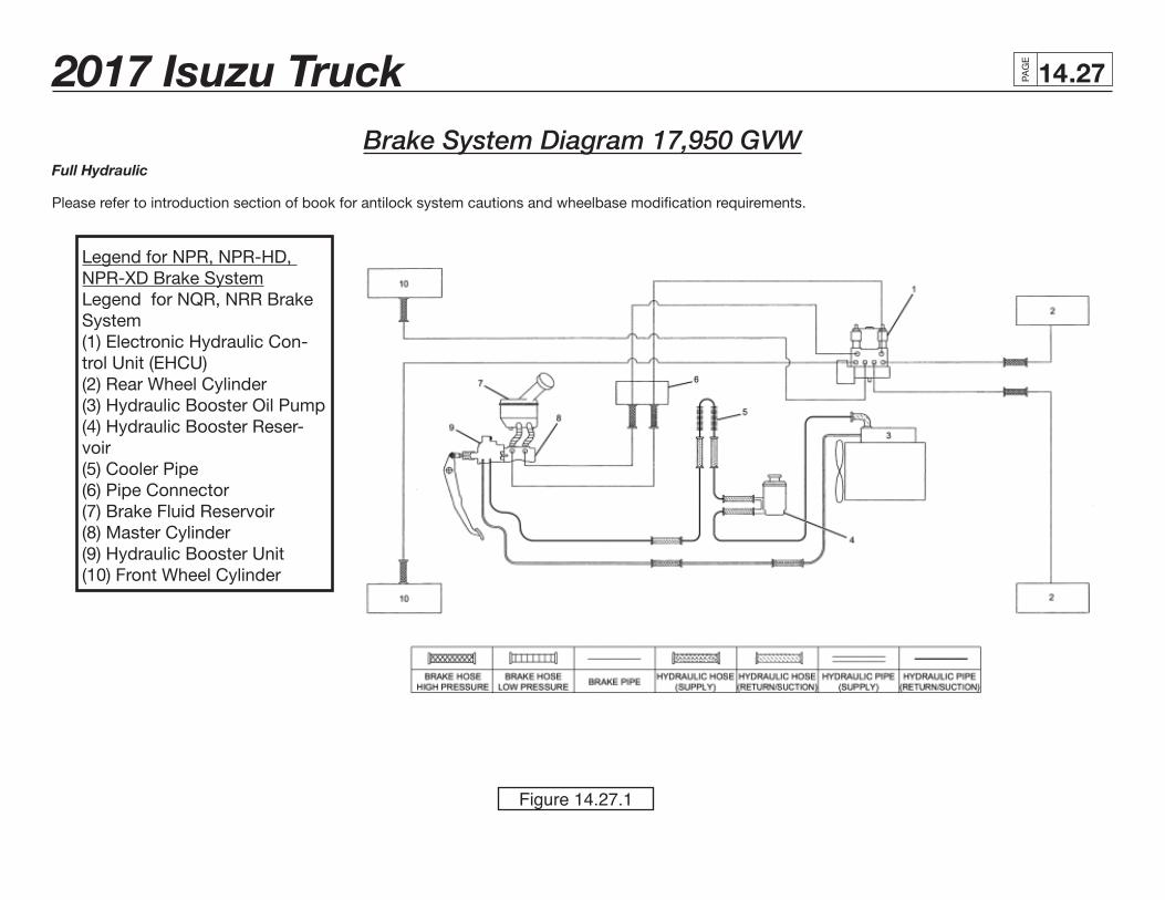
Brake System Diagram 17,950 GVWFull Hydraulic
Please refer to introduction section of book for antilock system cautions and wheelbase modification requirements.
Figure 14.27.1
Legend for NPR, NPR-HD, NPR-XD Brake SystemLegend for NQR, NRR Brake System(1) Electronic Hydraulic Con-trol Unit (EHCU)(2) Rear Wheel Cylinder(3) Hydraulic Booster Oil Pump(4) Hydraulic Booster Reser-voir(5) Cooler Pipe(6) Pipe Connector(7) Brake Fluid Reservoir(8) Master Cylinder(9) Hydraulic Booster Unit(10) Front Wheel Cylinder
2017 Isuzu Truck PAG
E
.2814
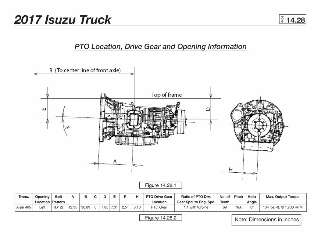
Trans. Opening Bolt A B C D E F H PTO Drive Gear Ratio of PTO Drv. No. of Pitch Helix Max. Output Torque Location Pattern Location Gear Spd. to Eng. Spd. Teeth Angle Aisin 465 Left (Dr 2) 12.35 36.89 0 7.85 7.31 2.50 5.16 PTO Gear 1:1 with turbine 69 N/A 00 134 lbs.-ft. @ 1,700 RPM
PTO Location, Drive Gear and Opening Information
Note: Dimensions in inches
Figure 14.28.1
Figure 14.28.2
2017 Isuzu Truck PAG
E
.2914
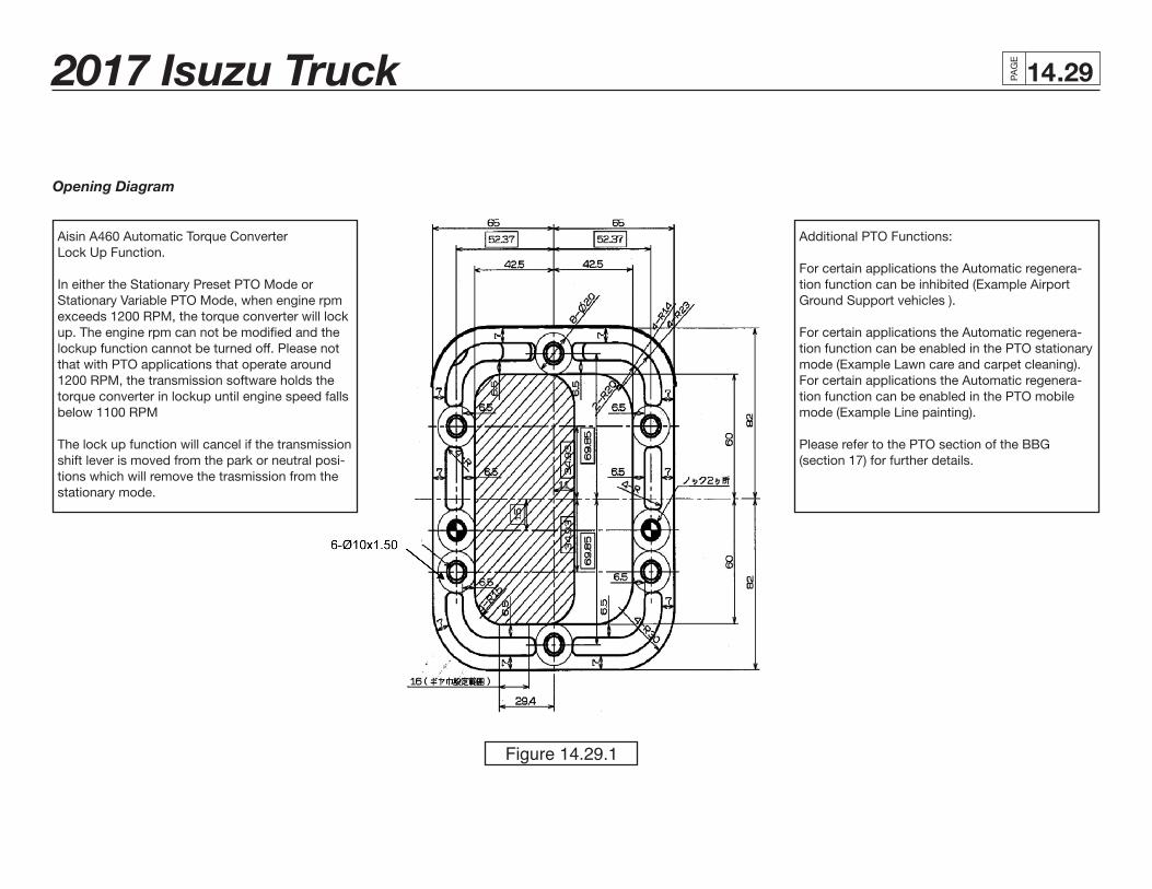
Opening Diagram
Aisin A460 Automatic Torque Converter Lock Up Function.
In either the Stationary Preset PTO Mode or Stationary Variable PTO Mode, when engine rpm exceeds 1200 RPM, the torque converter will lock up. The engine rpm can not be modified and the lockup function cannot be turned off. Please not that with PTO applications that operate around 1200 RPM, the transmission software holds the torque converter in lockup until engine speed falls below 1100 RPM
The lock up function will cancel if the transmission shift lever is moved from the park or neutral posi-tions which will remove the trasmission from the stationary mode.
Additional PTO Functions: For certain applications the Automatic regenera-tion function can be inhibited (Example Airport Ground Support vehicles ). For certain applications the Automatic regenera-tion function can be enabled in the PTO stationary mode (Example Lawn care and carpet cleaning). For certain applications the Automatic regenera-tion function can be enabled in the PTO mobile mode (Example Line painting). Please refer to the PTO section of the BBG (section 17) for further details.
Figure 14.29.1
2017 Isuzu Truck PAG
E
.3014
Diesel Fuel Fill
Installation Instructions
1. Disconnect battery.
2. Loosen hose from the tie downs. Remove caps from plate on rail.
3. Install hoses onto the plate.
4. Extend hose out from the driver side of the rail to body rail.
5. The filler neck must be mounted to allow the fill plate bracket to be parallel to the frame horizontal.
6. Cover with protector wrap and secure with tie wraps.
7. Filler hose is set for 102 inches outside width body.
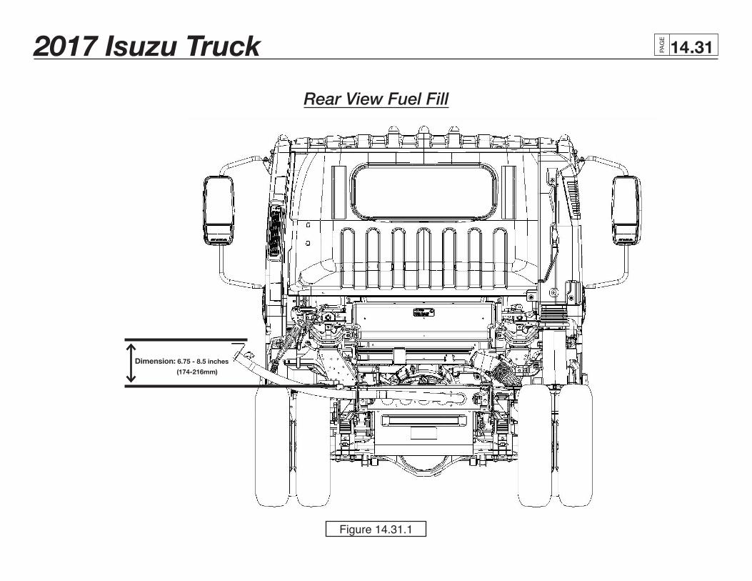
8. Filler neck (dimension A) must be between 6.85 inches and 8.5 inches above frame.
9. Secure the filler plate to the bottom of the body and check for leaks.
10. Ensure that fill hose does not sag, creating an area where the fuel could pool in the fill hose.
11. Reconnect battery.
2017 Isuzu Truck PAG
E
.3114
Rear View Fuel Fill
Dimension: 6.75 - 8.5 inches
(174-216mm)
Figure 14.31.1
2017 Isuzu Truck PAG
E
.3214
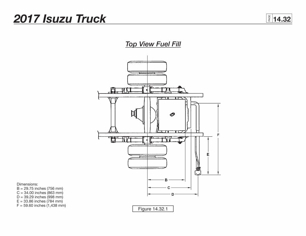
Top View Fuel Fill
Dimensions:B = 29.75 inches (756 mm)C = 34.00 inches (863 mm)D = 39.29 inches (998 mm)E = 33.86 inches (784 mm)F = 59.60 inches (1,438 mm)
Figure 14.32.1
2017 Isuzu Truck PAG
E
.3314
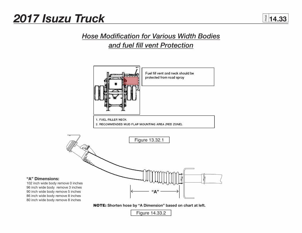
Hose Modification for Various Width Bodiesand fuel fill vent Protection
“A” Dimensions: 102 inch wide body remove 0 inches96 inch wide body remove 3 inches90 inch wide body remove 5 inches86 inch wide body remove 8 inches80 inch wide body remove 8 inches
NOTE: Shorten hose by “A Dimension” based on chart at left.
“A”
Figure 13.32.1
Figure 14.33.2
2017 Isuzu Truck PAG
E
.3414
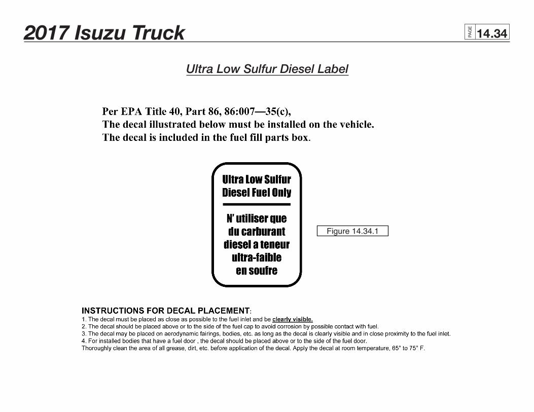
Ultra Low Sulfur Diesel Label
Figure 14.34.1
2017 Isuzu Truck PAG
E
.3514
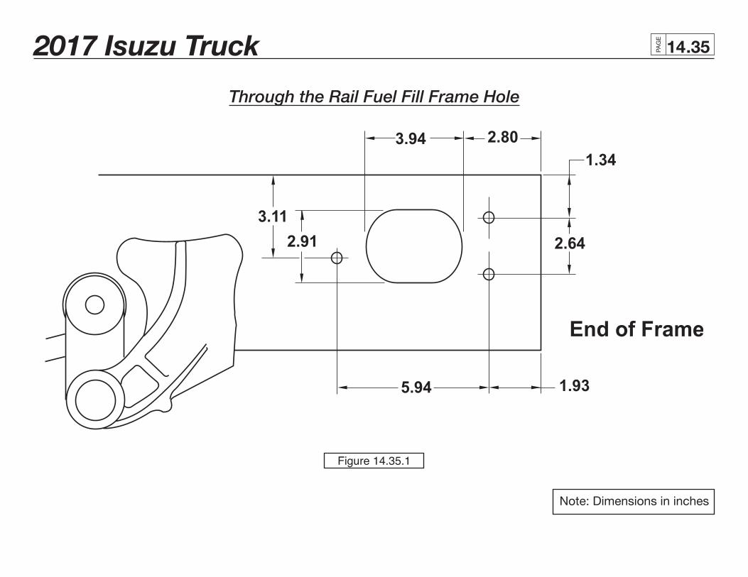
Through the Rail Fuel Fill Frame Hole
Note: Dimensions in inches
Figure 14.35.1
2017 Isuzu Truck PAG
E
.3614
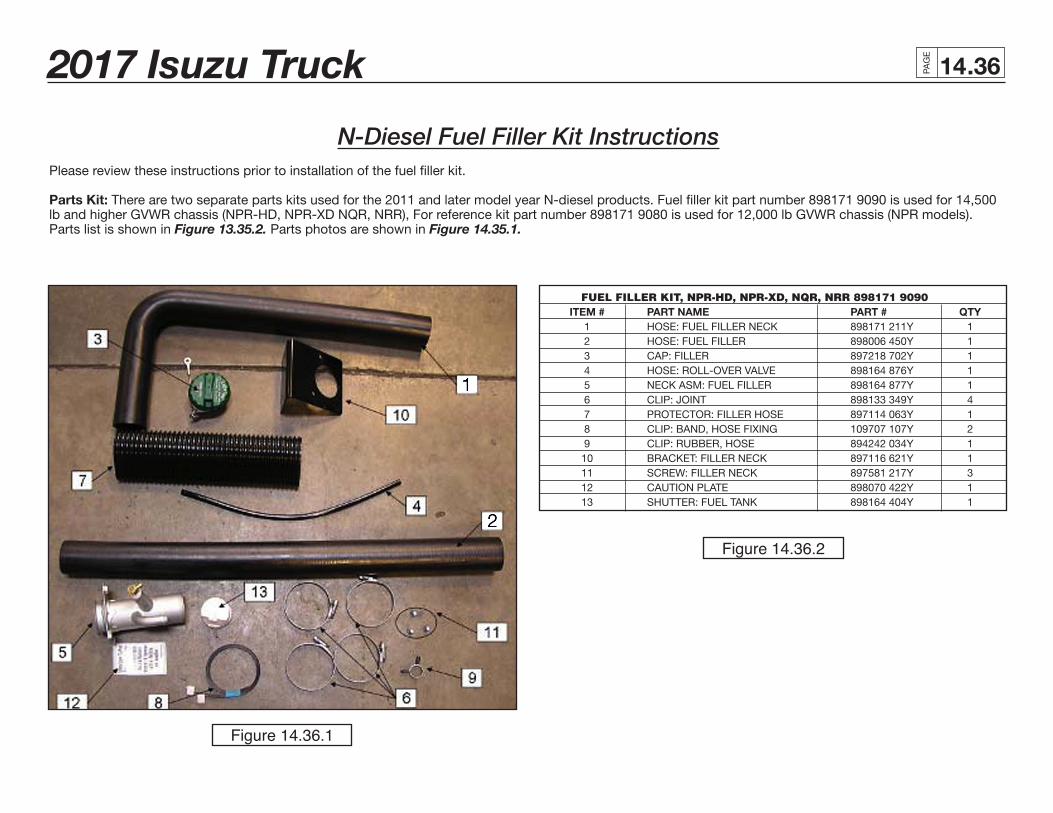
N-Diesel Fuel Filler Kit InstructionsPlease review these instructions prior to installation of the fuel filler kit.
Parts Kit: There are two separate parts kits used for the 2011 and later model year N-diesel products. Fuel filler kit part number 898171 9090 is used for 14,500 lb and higher GVWR chassis (NPR-HD, NPR-XD NQR, NRR), For reference kit part number 898171 9080 is used for 12,000 lb GVWR chassis (NPR models). Parts list is shown in Figure 13.35.2. Parts photos are shown in Figure 14.35.1.
FUEL FILLER KIT, NPR-HD, NPR-XD, NQR, NRR 898171 9090 ITEM # PART NAME PART # QTY 1 HOSE: FUEL FILLER NECK 898171 211Y 1 2 HOSE: FUEL FILLER 898006 450Y 1 3 CAP: FILLER 897218 702Y 1 4 HOSE: ROLL-OVER VALVE 898164 876Y 1 5 NECK ASM: FUEL FILLER 898164 877Y 1 6 CLIP: JOINT 898133 349Y 4 7 PROTECTOR: FILLER HOSE 897114 063Y 1 8 CLIP: BAND, HOSE FIXING 109707 107Y 2 9 CLIP: RUBBER, HOSE 894242 034Y 1 10 BRACKET: FILLER NECK 897116 621Y 1 11 SCREW: FILLER NECK 897581 217Y 3 12 CAUTION PLATE 898070 422Y 1 13 SHUTTER: FUEL TANK 898164 404Y 1
Figure 14.36.2
Figure 14.36.1
2017 Isuzu Truck PAG
E
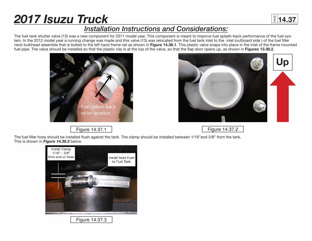
.3714Installation Instructions and Considerations:
The fuel tank shutter valve (13) was a new component for 2011 model year. This component is meant to improve fuel splash-back performance of the fuel sys-tem. In the 2012 model year a running change was made and this valve (13) was relocated from the fuel tank inlet to the inlet (outboard side ) of the fuel filler neck bulkhead assemble that is bolted to the left hand frame rail as shown in Figure 14.38.1. This plastic valve snaps into place in the inlet of the frame mounted fuel pipe. The valve should be installed so that the plastic clip is at the top of the valve, so that the flap door opens up, as shown in Figures 13.38.2.
The fuel filler hose should be installed flush against the tank. The clamp should be installed between 1/16”and 3/8” from the tank. This is shown in Figure 14.38.3 below.
Up
Figure 14.37.1 Figure 14.37.2
Figure 14.37.3
2017 Isuzu Truck PAG
E
.3814
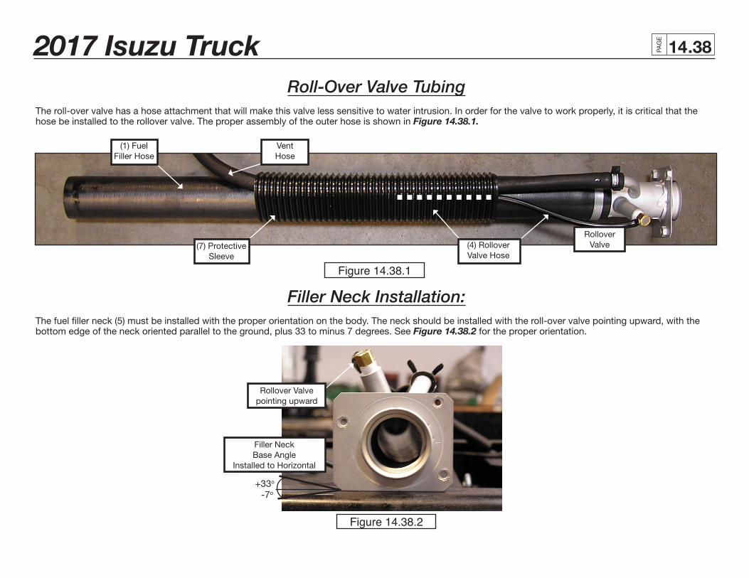
Roll-Over Valve TubingThe roll-over valve has a hose attachment that will make this valve less sensitive to water intrusion. In order for the valve to work properly, it is critical that the hose be installed to the rollover valve. The proper assembly of the outer hose is shown in Figure 14.38.1.
(1) FuelFiller Hose
Vent Hose
(7) Protective Sleeve
RolloverValve
Filler Neck Installation:The fuel filler neck (5) must be installed with the proper orientation on the body. The neck should be installed with the roll-over valve pointing upward, with the bottom edge of the neck oriented parallel to the ground, plus 33 to minus 7 degrees. See Figure 14.38.2 for the proper orientation.
Rollover Valve pointing upward
Filler Neck Base Angle
Installed to Horizontal
+33o
-7o
(4) RolloverValve Hose
Figure 14.38.1
Figure 14.38.2