Embed Size (px)
Citation preview

SUBMITTAL TRANSMITTAL
Date Sent 4102017 Job 2016913
Project Name 40 Tenth Avenue
Transmittal LOT-2016913-S170
From
Jeremy Behrhorst
Cauldwell Wingate Company
380 Lexington Avenue New York NY 10168
Phone 212-983-7150 Fax 212-983-7275
To
StructureTech NY
90 West Sandford Boulevard Mount Vernon NY 10550
CC
Aurora Capital Associates
Spec Section 030000 Submittal Type Product Data ScopeArea
Distribution E-Mail wLinks (Merged Copy)
Package Company Contact Comments
StructureTech NY
Submittal listing
Submittal Doc Doc Date Item Subject Action
250 Hilti HIT-HY 100 NR
ACTION CODES
A Approved B Approved As Noted B1 Resubmit for Record
C Revise amp Resubmit D Rejected RNR ReviewedNot Reviewed
REMARKS
Reviewed for Compliance with Contract Documents and Specifications
SUBMISSION LINKRETURN DOCUMENT
250_Hilti HIT-HY 100_Not Reviewed_041017pdf
PDF File 318 MB
httpsportalcwingatecomsites2016913Submittals030000030000s25r0ret193pdf
SUBMITTAL TRANSMITTAL
Date Sent 362017 Job 2016913
Project Name 40 Tenth Avenue
Transmittal LOT-2016913-S25
From
Jeremy Behrhorst
Cauldwell Wingate Company
380 Lexington Avenue New York NY 10168
Phone 212-983-7150 Fax 212-983-7275
To
Studio Gang Architects
50 Broad Street Suite 1901 New York NY 10004
CC
Aurora Capital Associates
PLEASE REVIEW AND RETURN BY 031617
return priority Standard
nmlkji Critical nmlkji
Spec Section 030000 Submittal Type Product Data ScopeArea
Distribution E-Mail wLinks (Merged Copy)
Package Company Contact Comments
Studio Gang Architects
Submittal listing
Submittal Doc Doc Date Item Subject Action
250 Hilti HIT-HY 100 For Approval
REMARKS
Reviewed for Compliance with Contract Documents and Specifications
SUBMISSION LINKRETURN DOCUMENT
250_Hilti HIT-HY 100_For Approval_031617pdf PDF File 211 MB
httpsportalcwingatecomsites2016913Submittals030000030000-250pdf
SUBMITTALTo Jeremy Behrhorst Date 021517
Company Cauldwell Wingate Job J0368
From Tom Wang Submittal 033000-17-C-9
Re 40 10th Ave Foundation
HILTI HIT-HY 100
Stamp by Engineer
Stamp by Architect
Signed TW Date 021517
StructureTech NY
Signed Date
Cauldwell Wingate
Location To be used for embed (or missing) anchoring rebar dowels
SUBMITTAL 250 03-06-17
Shaina Saporta Apr 02 2017
Not for structural applications
x
A - No Exception Taken B - Make Corrections Noted and Proceed with Fabrication Revise and Resubmit for RecordC - Revise and Resubmit and Do Not Proceed with FabricationD - RejectedIncompleteE - Reviewed for Conformance with Contract DocumentsF - Not Reviewed Information OnlyG - Reviewed Information Only
SGA
Date Returned
Date Received
SGA Project Number
Submittal Number
Submittal Description
Refer to Division One and the General Conditions The Architectrsquos review of the Contractorrsquos submission shall not relieve the Contractor of any obligation contained in the Contract Documents The Architectrsquos review shall not constitute approval of means methods or safety procedures The Architectrsquos review of a specific item shall not indicate approval of an assembly of which the item is a component
STUDIOGANGARCHITECTS50 Broad Street Suite 1901 New York NY 10004
T 212-579-1514 15009
250
Hilti HITshyHY 100
3062017
X
BS
4072017
HIT-HY 100 Adhesive Anchor Technical Supplement
Setting the standard for performance and reliabilityHilti Outperform Outlast
SUBMITTAL 250
03-06-17
Hilti Outperform Outlast
2 Hilti Inc (USA) 1-800-879-8000 I wwwushilticom I en espantildeol 1-800-879-5000 I Hilti (Canada) Corp 1-800-363-4458 I wwwhiltica I HIT-HY 100 Technical Supplement 0114
The new Hilti HIT-HY 100 Adhesive Anchoring System is the latest addition to the fast cure adhesive anchor portfolio and designed for solid performance in a wide range of applications Designed to utilize the existing Hilti dispenser platform and ICC-ES approved for uncracked concrete this anchor is the perfect complement to the portfolio for day to day jobsite needs
Setting the standard for performance and reliability HIT-HY 100 Adhesive Anchoring System
Hilti Adhesive Anchors mdash every job every application
HY 200 SAFEset HY 200 HY 100 HY 10+
Performance ◼ ICC approved for uncracked concrete
◼ Complete anchor system available including HIT-V HAS-E and HIS rods
◼ Easy and accurate dispensing with battery dispenser
Reliability ◼ Reliable fastenings using the traditional cleaning method (2x2x2)
◼ Tested with wide range of rod diameters and embedments
SUBMITTAL 250
03-06-17
HIT-HY 100 Adhesive Anchoring System
HIT-HY 100 Adhesive Anchoring System
3Hilti Inc (USA) 1-800-879-8000 I wwwushilticom I en espantildeol 1-800-879-5000 I Hilti (Canada) Corp 1-800-363-4458 I wwwhiltica I HIT-HY 100 Technical Supplement 0114
HIT-HY 100 Hybrid Adhesive Features and Applications
◼ Anchoring light structural steel connections (eg steel columns beams)
◼ Anchoring secondary steel elements ◼ Rebar doweling and connecting secondary
post-installed rebar ◼ Substituting misplaced or missing rebar ◼ ICC approved for un-cracked concrete ◼ Tested with a wide range of rod diameters
and embedments ◼ Complete anchor system available
including HIT-V rods HAS-E rods and HIS inserts
◼ Easy and accurate dispensing with battery dispenser
Technical Data HIT-HY 100Product Hybrid Urethane
Methacrylate
Base material temperature
14deg F to 104deg F(-10deg C to 40deg C)
Diameter range 38 to 1-14
ListingsApprovalsbull ICC-ES (International Code Council) ndash
ESR-3574 for un-cracked concrete bull COLA (City of Los Angeles) (pending)
Package volumebull Volume of HIT-HY 100 111 fl oz330 ml foil pack
is 201 in3
bull Volume of HIT-HY 100 169 fl oz500 ml foil pack is 305 in3
WorkingFull Cure Time Table (Approximate)Base Material Temperature
deg F deg C twork tcure
14 22 -10 -5 3 h 12 hrs23 31 -4 0 40 min 4 hrs32 40 1 5 20 min 2 hrs41 50 6 10 8 min 60 min51 68 11 20 5 min 30 min69 86 21 30 3 min 30 min
87 104 31 40 2 min 30 min
Order Information Description Qty of foil packs Item No
HIT-HY 100 (111oz330ml) 1 02078494HIT-HY 100 Master Carton (111oz330ml) 25 03510989HIT-HY 100 Master Carton (111oz330ml) + HDM 500 25 03510991HIT-HY 100 Master Carton (169oz500ml) 20 02078495(2) HIT-HY 100 Master Cartons (169oz500ml) + HDM 500 40 03511063(2) HIT-HY 100 Master Cartons (169oz500ml) + HDE 500 Kit 40 03511064
Accessories Description Item No
HDM 500 Manual Dispenser 03498241HDE 500 Compact Cordless Dispenser 03496606HDE 500 Industrial Cordless Dispenser 03496605
SUBMITTAL 250 03-06-17
HIT-HY 100 Adhesive Anchoring System
HIT-HY 100 Adhesive Anchoring System
4 Hilti Inc (USA) 1-800-879-8000 I wwwushilticom I en espantildeol 1-800-879-5000 I Hilti (Canada) Corp 1-800-363-4458 I wwwhiltica I HIT-HY 100 Technical Supplement 0114
10 Product Description
20 Technical Data
ListingsApprovalsICC-ES (International Code Council) ESR-3574
NSFANSI Standard 61 Certification for use of HIT-HY 100 in potable water
Independent Code EvaluationIBCregIRCreg 2009 (ICC-ES AC308)
IBCregIRCreg 2006 (ICC-ES AC308)
IBCregIRCreg 2003 (ICC-ES AC308)
LEEDreg Credit 41-Low Emitting Materials
The Leadership in Energy and Environmental Design (LEED) Green Building Rating systemtrade is the nationally accepted benchmark for the design construction and operation of high performance green buildings
10 Product Description
The Hilti HIT-HY 100 Adhesive Anchoring System is used to resist static wind or earthquake (Seismic Design Categories A and B only) tension and shear loads in normal-weight concrete having a compressive strength f´c of 2500 psi to 8500 psi (172 MPa to 586 MPa) It is suitable to be used in uncracked concrete as defined per ICC-ES ACI and CSA
Hilti HIT-HY 100 Adhesive is an injectable two-component hybrid adhesive The two components are separated by means of a dual-cylinder foil pack attached to a manifold The two components combine and react when dispensed through a static mixing nozzle attached to the manifold
Elements that are suitable for use with this system are as follows threaded steel rods Hilti HIS-(R)N steel internally threaded inserts and steel reinforcing bars
Hilti HIT-HY 100 Adhesive Technical Data Table of Contents
Element Type Rebar Hilti HAS Threaded Rod
Hilti HIS-N and HIS-RN Internally Threaded Insert
United States Canada
Pages 9 ndash 15 16 ndash 19 20 ndash 26 27 ndash 29
Tables 1 ndash 10 11 ndash 17 18 ndash 27 28 ndash 30
Information on Working Time and Cure Time on page 30 Information on Resistance of Cured Hilti HIT-HY 100 to Chemicals on page 30
SUBMITTAL 250 03-06-17
HIT-HY 100 Adhesive Anchoring System
HIT-HY 100 Adhesive Anchoring System
5Hilti Inc (USA) 1-800-879-8000 I wwwushilticom I en espantildeol 1-800-879-5000 I Hilti (Canada) Corp 1-800-363-4458 I wwwhiltica I HIT-HY 100 Technical Supplement 0114
20 Technical Data21 Testing and Product
EvaluationHilti HIT-HY 100 has been tested in accordance with ICC Evaluation Services (ICC-ES) Acceptance Criteria for Post-Installed Adhesive Anchors in Concrete Elements (AC308)
Hilti has had Hilti HIT-HY 100 evaluated according to AC308 and has received ESR-3574 from ICC-ES
22 Adhesive Anchor Design Codes
221 United StatesFor post-installed and cast-in anchor systems design calculations are performed according to ACI 318 Appendix D This has been a requirement of the International Building Code (IBC) since 2003 ACI 318-11 Appendix D introduced for the first time specific equations for the design of adhesive anchor systems using threaded rod or rebar Prior to this only post-installed expansion and undercut anchors and cast-in headed studs were recognized
Prior to the publication of ACI 318-11 designers of post-installed adhesive anchor systems used ACI 318-08 Appendix D and Section 33 of AC308 which provides amendments to Appendix D These amendments provide the relevant equations to design a post-installed adhesive anchor
At the time of this publication ESR-3574 for Hilti HIT-HY 100 includes the design provisions for ACI 318-08 and AC308 Section 33
222 CanadaCSA A233-04 Annex D provides the required limit states design equations for post-installed mechanical anchors and for cast-in headed studs At the time of this publication Annex D which is a non-mandatory part of the Canadian code does not address adhesive anchor design or test criteria
Since Annex D does not provide guidance for the design of adhesive anchor systems it is the position of Hilti that the design provisions of ACI 318-11 Appendix D can be used for the design of Hilti HIT-HY 100 in Canada The foundations of a proper adhesive anchor design are now well established through ACI 318-11 and a proper chemical anchor design in the United States would be also relevant in Canada It will be shown in later sections how to relate the results from technical data in this supplement to the Canadian design standard
23 Design of Hilti HIT-HY 100 Adhesive Anchor System
231 Using technical data in ESR-3574
Technical data for the system components of Hilti HIT-HY 100 can be found in ICC-ES ESR-3574 This includes
bull Hilti HIT-HY 100 adhesive
bull Standard threaded rods and rebar
bull Hilti HIS-(R)N internally threaded inserts
A designer can use the data in ESR-3574 to calculate the capacity of the Hilti HIT-HY 100 system in the following manner
bull For standard threaded rods rebar and the Hilti HIS-(R)Ninternally threaded inserts a design using either ACI 318-11Appendix D or ACI 318-08 Appendix D and AC308 Section33 amendments to ACI 318 would be appropriate
The tables from ESR-3574 are not included in this supplement but can be found by downloading ESR-3574 from wwwushilticom or on the ICC-ES website at wwwicc-esorg or by contacting your local Hilti representative
232 Using the New Hilti Simplified Design Tables
In lieu of providing a copy of ESR-3574 design tables in this supplement Hilti is providing a new simple approach for designing an anchor according to the current codes described in Section 22 Refer to Section 24 for a description of these new innovative tables
24 Hilti Simplified Design TablesThe Hilti Simplified Design Tables is not a new ldquomethodrdquo of designing an anchor that is different than the provisions of ACI 318 Appendix D or CSA A233 Annex D Rather it is a series of pre-calculated tables and reduction factors meant to help the designer create a quick calculation of the capacity of the Hilti anchor system and still be compliant with the codes and criteria of ACI and CSA
The Hilti Simplified Design Tables are formatted similar to the Allowable Stress Design (ASD) tables and reduction factors which was a standard of practice for design of post-installed anchors
The Hilti Simplified Design Tables combine the simplicity of performing a calculation according to the ASD method with the code-required testing evaluation criteria and technical data in ACI Appendix D and CSA Annex D
SUBMITTAL 25003-06-17
HIT-HY 100 Adhesive Anchoring System
HIT-HY 100 Adhesive Anchoring System
6 Hilti Inc (USA) 1-800-879-8000 I wwwushilticom I en espantildeol 1-800-879-5000 I Hilti (Canada) Corp 1-800-363-4458 I wwwhiltica I HIT-HY 100 Technical Supplement 0114
241 Simplified Tables Data Development
The Simplified Tables have two table types The single anchor capacity table and the reduction factor table
Single anchor capacity tables show the design strength (for ACI) or factored resistance (for CSA) in tension and shear for a single anchor This is the capacity of a single anchor with no edge distance or concrete thickness influences and is based on the assumptions outlined in the footnotes below each table
Reduction factor tables are created by comparing the single anchor capacity to the capacity that includes the influence of a specific edge distance spacing or concrete thickness using the equations of ACI 318-11 Appendix D
The single anchor tension capacity is based on the lesser of concrete breakout strength or bond strength
ACI ФNn = min | ФNcb ФNa | CSAACI Nr = min | Ncbr Na |
ФNn = Nr
The shear value is based on the pryout strength
ACI ФVn = ФVcp CSAACI Vr = Vcpr
ФVn = Vr
Concrete breakout is calculated according to ACI 318 Appendix D and CSA A233 Annex D using the variables from ESR-3574 These values are equivalent
Bond strength is not recognized in CSA so this is determined from ACI 318-11 Appendix D for both the US and Canada
242 Steel Strength for All Elements
The steel strength is provided on a separate table and is based on calculations from ACI 318 Appendix D and CSA A233 Annex D ACI and CSA have different reduction factors for steel strength thus the values for both ACI and CSA are published
243 How to Calculate Anchor Capacity Using Simplified Tables
The process for calculating the capacity of a single anchor or anchor group is similar to the ASD calculation process currently outlined in the 2011 North American Product Technical Guide Volume 2 Anchor Fastening Technical Guide on page 19
The design strength (factored resistance) of an anchor is obtained as follows
Tension
ACI Ndes = n bull min | ФNn bull fAN bull fRN ФNsa |
CSA Ndes = n bull min | Nr bull fAN bull fRN Nsr |
Shear
ACI Vdes = n bull min | ФVn bull fAV bull fRV bull fHV ФVsa |
CSA Vdes = n bull min | Vr bull fAV bull fRV bull fHV Vsr |
where
n = number of anchorsNdes = design resistance in tension
ФNn = design strength in tension considering concrete breakout pullout or bond failure (ACI)
ФNsa = design strength in tension considering steel failure (ACI)
Nr = factored resistance in tension considering concrete breakout pullout or bond failure (CSA)
Nsr = factored resistance in tension considering steel failure (CSA)
Vdes = design resistance in shear ФVn = design strength in shear considering
concrete failure (ACI) ФVsa = design strength in shear considering steel
failure (ACI)Vr = factored resistance in shear considering
concrete failure (CSA)Vsr = factored resistance in shear considering steel
failure (CSA)fAN = adjustment factor for spacing in tensionfRN = adjustment factor for edge distance in tensionfAV = adjustment factor for spacing in shearfRV = adjustment factor for edge distance in shearfHV = adjustment factor for concrete thickness in
shear (this is a new factor that ASD did not use previously)
Adjustment factors are applied for all applicable near edge and spacing conditions
For example the capacity in tension corresponding to the anchor group based on worst case anchor ldquoardquo in the figure below is evaluated as follows
ACI Ndes = 4 bull ФNn bull fAx bull fAy bull fRx bull fRy
CSA Ndes = 4 bull Nr bull fAx bull fAy bull fRx bull fRy
SUBMITTAL 25003-06-17
HIT-HY 100 Adhesive Anchoring System
HIT-HY 100 Adhesive Anchoring System
7Hilti Inc (USA) 1-800-879-8000 I wwwushilticom I en espantildeol 1-800-879-5000 I Hilti (Canada) Corp 1-800-363-4458 I wwwhiltica I HIT-HY 100 Technical Supplement 0114
Note designs are for orthogonal anchor bolt patterns and no reduction factor for the diagonally located adjacent anchor is required
Where anchors are loaded simultaneously in tension and shear interaction must be considered The interaction equation is as follows
Nua Vua ACI ____ + ____ le 12Ndes Vdes
Nf Vf CSA ____ + ____ le 12 Ndes Vdes
where
Nua = Required strength in tension based on factored load combinations of ACI 318 Chapter 9
Vua = Required strength in shear based on factored load combinations of ACI 318 Chapter 9
Nf = Required strength in tension based on factored load combinations of CSA A233 Chapter 8
Vf = Required strength in shear based on factored load combinations of CSA A233 Chapter 8
The full tension strength can be permitted if Vua ACI _____ le 02 Vdes
Vf CSA ____ le 02Vdes
The full shear strength can be permitted if Nua ACI ____ le 02Ndes
Nf CSA ____ le 02Ndes
244 Allowable Stress Design (ASD)
The values of Ndes and Vdes developed from Section 243 are design strengths (factored resistances) and are to be compared to the required strength in tension and shear from factored load combinations of ACI 318 Chapter 9 or CSA A233 Chapter 8
The design strength (factored resistance) can be converted to an ASD value as follows
NdesNdesASD = _____
αASD
VdesVdesASD = _____
αASD
whereαASD = Conversion factor calculated as a weighted
average of the load factors for the controlling load combination
An example for the calculation of αASD is as follows
Controlling strength design load combination is 12D + 16L contribution is 30 D 70 L
αASD = 12 x 030 + 16 x 070 = 148
245 Sustained Loads and Overhead Use
Sustained loading is calculated by multiplying the value of ФNn or Nr by 055 and comparing the value to the tension dead load contribution (and any sustained live loads or other loads) of the factored load Edge spacing and concrete thickness influences do not need to be accounted for when evaluating sustained loads
Consideration of sustained loads is based on ACI 318-11 Appendix D Since sustained loading is not addressed in CSA A233 Annex D it is reasonable to use this approach for CSA based designs
246 Accuracy of the Simplified Tables
Calculations using the Simplified Tables have the potential of providing a design strength (factored resistance) that is exactly what would be calculated using equations from ACI 318 Appendix D or CSA A233 Annex D
The tables for the single anchor design strength (factored resistance) for concrete bond pullout failure or steel failure have the same values that will be computed using the provisions of ACI and CSA
The load adjustment factors for edge distance influences are SUBMITTAL 250
03-06-17
HIT-HY 100 Adhesive Anchoring System
HIT-HY 100 Adhesive Anchoring System
8 Hilti Inc (USA) 1-800-879-8000 I wwwushilticom I en espantildeol 1-800-879-5000 I Hilti (Canada) Corp 1-800-363-4458 I wwwhiltica I HIT-HY 100 Technical Supplement 0114
based on a single anchor near an edge The load adjustment factors for spacing are determined from the influence of two adjacent anchors Each reduction factor is calculated for the minimum value of either concrete or bond failure When more than one edge distance andor spacing condition exists the load adjustment factors are multiplied together This will result in a conservative design when compared to a full calculation based on ACI or CSA Additionally if the failure mode in the single anchor tables is controlled by concrete failure and the reduction factor is controlled by bond failure this will also give a conservative value (and vice versa)
The following is a general summary of the accuracy of the simplified tables
bull Single anchor tables have values equivalent to acalculation according to ACI or CSA
bull Since the table values including load adjustment factorsare calculated using equations that are not linear linearinterpolation is not permitted Use the smaller of the twotable values listed This provides a conservative valueif the application falls between concrete compressivestrengths embedment depths or spacing edgedistance and concrete thickness
bull For one anchor near one edge applying the edgedistance factor typically provides accurate valuesprovided the failure mode of the table values is thesame If the failure mode is not the same the values areconservative
bull For two to four anchors in tension with no edgereductions applying the spacing factors provides a valuethat is equivalent to the ACI and CSA calculated valuesprovided the controlling failure modes of the table valuesare the same If the failure mode is not the same thevalues are conservative
bull The spacing factor in shear is conservative whencompared to two anchors with no edge distanceconsiderations This factor is based on spacing nearan edge and can be conservative for installations awayfrom the edge of the concrete member Note for lessconservative results it is possible to use the spacingfactor in tension for this application if there is no edgedistance to consider
bull The concrete thickness factor in shear is conservativewhen compared to an anchor with no edge influencesThis factor is based on applications near an edge In themiddle of a concrete member this is conservative Notefor less conservative results this factor can be ignored ifthe application is not near an edge
bull The load adjustment factors are determined bycalculations according to ACI 318-11 Appendix D This ismore conservative than ACI 318-08 Appendix D becausethe ψ
gNa factor which is always greater than or equal to10 does not need to be calculated
IMPORTANT NOTE
For applications such as a four bolt or six bolt anchor pattern in a corner in a thin slab the calculation can be up to 80 conservative when compared to a calculation according to ACI or CSA It is always suggested to perform a calculation by hand using the provisions of ACI and CSA to optimize the design This is especially true when the Simplified Table calculation does not provide a value that satisfies the design requirements The fact that a Simplified Table calculation does not exceed a design load does not mean the HIT-HY 100 Adhesive system will not fulfill the design requirements Additional assistance can be given by your local Hilti representative
247 Limitations Using Simplified Tables
There are additional limitations that the Simplified Tables do not consider
bull Load Combinations Table values are meant to be usedwith the load combinations of ACI 318 Section 92 andCSA A233 Chapter 8
bull Supplementary Reinforcement Table values includingreduction factors are based on Condition B which doesnot consider the effects of supplementary reinforcementnor is there an influence factor that can be applied toaccount for supplementary reinforcement
bull Eccentric loading Currently there is not a method forapplying a factor to the tables to account for eccentricloading
bull Moments or Torsion While a designer can apply amoment or torsion to the anchor system and obtain aspecific load per anchor the tables themselves do nothave specific factors to account for moments or torsionapplied to the anchor system
bull Standoff Standoff is not considered in the steel designtables
bull Anchor layout The Simplified Tables assume anorthogonal layout
There may be additional applications not noted above Contact Hilti with any questions for specific applications
SUBMITTAL 25003-06-17
HIT-HY 100 Adhesive Anchoring System
HIT-HY 100 Adhesive Anchoring System
9Hilti Inc (USA) 1-800-879-8000 I wwwushilticom I en espantildeol 1-800-879-5000 I Hilti (Canada) Corp 1-800-363-4458 I wwwhiltica I HIT-HY 100 Technical Supplement 0114
248 Hilti HIT-HY 100 Adhesive with Deformed Reinforcing Bars (Rebar)
Rebar Installation Conditions
Perm
issi
ble
Con
cret
e C
ondi
tions
UncrackedConcrete
DryConcrete
Perm
issi
ble
Dril
ling
Met
hod
Hammer Drilling with Carbide Tipped Drill Bit Water Saturated
Concrete
US Rebar Installation Specifications
RebarSize
DrillBitDia
StandardEmbedDepth
EmbedDepthRange
MinimumBase
MaterialThickness
oslashdin
hef std
in (mm) hef
in (mm) hmin
in (mm)
3 123-38 2-38 ndash 7-12
hef + 1-14(hef + 30)
(86) (60 ndash 191)
4 584-12 2-34 ndash 10(114) (70 ndash 254)
5 345-58 3-18 ndash 12-12
hef + 2d0
(143) (79 ndash 318)
6 786-34 3-12 ndash 15(171) (89 ndash 381)
7 17-78 3-12 ndash 17-12(200) (89 ndash 445)
8 1-189 4 ndash 20
(229) (102 ndash 508)
9 1-3810-18 4-12 ndash 22-12(257) (114 ndash 572)
10 1-1211-14 5 ndash 25(286) (127 ndash 635)
Canadian Rebar Installation Specifications
RebarSize
DrillBitDia
StandardEmbedDepth
EmbedDepthRange
MinimumBase
MaterialThickness
oslashdin
hef std
mm hef
mm hmin
mm10 M 916 115 70 ndash 226 hef + 3015 M 34 145 80 ndash 320
hef + 2d0
20 M 1 200 90 ndash 39025 M 1-14 230 101 ndash 50430 M 1-12 260 120 ndash 598
SUBMITTAL 25003-06-17
HIT-HY 100 Adhesive Anchoring System
HIT-HY 100 Adhesive Anchoring System
10 Hilti Inc (USA) 1-800-879-8000 I wwwushilticom I en espantildeol 1-800-879-5000 I Hilti (Canada) Corp 1-800-363-4458 I wwwhiltica I HIT-HY 100 Technical Supplement 0114
Table 1 mdash Hilti HIT-HY 100 Adhesive Design Strength (Factored Resistance) with Concrete Bond Failure for US Rebar in Uncracked Concrete 12345678
NominalRebar Size
EffectiveEmbedment
Depthin (mm)
Tension mdash ϕNn or Nr Shear mdash ϕVn or Vr
f´c = 2500 psi (172 Mpa)
lb (kN)
f´c = 3000 psi (207 Mpa)
lb (kN)
f´c = 4000 psi (276 Mpa)
lb (kN)
f´c = 6000 psi (414 Mpa)
lb (kN)
f´c = 2500 psi (172 Mpa)
lb (kN)
f´c = 3000 psi (207 Mpa)
lb (kN)
f´c = 4000 psi (276 Mpa)
lb (kN)
f´c = 6000 psi (414 Mpa)
lb (kN)
3
3-38 3155 3155 3155 3340 6790 6790 6790 7200(86) (140) (140) (140) (149) (302) (302) (302) (320)
4-12 4205 4205 4205 4455 9055 9055 9055 9600(114) (187) (187) (187) (198) (403) (403) (403) (427)7-12 7005 7005 7005 7425 15090 15090 15090 15995(191) (312) (312) (312) (330) (671) (671) (671) (711)
4
4-12 5605 5605 5605 5940 12075 12075 12075 12800(114) (249) (249) (249) (264) (537) (537) (537) (569)
6 7475 7475 7475 7920 16100 16100 16100 17065(152) (333) (333) (333) (352) (716) (716) (716) (759)10 12455 12455 12455 13205 26830 26830 26830 28440
(254) (554) (554) (554) (587) (1193) (1193) (1193) (1265)
5
5-58 8760 8760 8760 9285 18865 18865 18865 19995(143) (390) (390) (390) (413) (839) (839) (839) (889)7-12 11680 11680 11680 12380 25150 25150 25150 26660(191) (520) (520) (520) (551) (1119) (1119) (1119) (1186)
12-12 19465 19465 19465 20630 41920 41920 41920 44435(318) (866) (866) (866) (918) (1865) (1865) (1865) (1977)
6
6-34 12610 12610 12610 13370 27165 27165 27165 28795(171) (561) (561) (561) (595) (1208) (1208) (1208) (1281)
9 16815 16815 16815 17825 36220 36220 36220 38395(229) (748) (748) (748) (793) (1611) (1611) (1611) (1708)15 28025 28025 28025 29710 60365 60365 60365 63990
(381) (1247) (1247) (1247) (1322) (2685) (2685) (2685) (2846)
7
7-78 17165 17165 17165 18195 36975 36975 36975 39190(200) (764) (764) (764) (809) (1645) (1645) (1645) (1743)
10-12 22890 22890 22890 24260 49300 49300 49300 52255(267) (1018) (1018) (1018) (1079) (2193) (2193) (2193) (2324)
17-12 38150 38150 38150 40435 82165 82165 82165 87095(445) (1697) (1697) (1697) (1799) (3655) (3655) (3655) (3874)
8
9 21060 22420 22420 23765 45360 48295 48295 51190(229) (937) (997) (997) (1057) (2018) (2148) (2148) (2277)12 29895 29895 29895 31690 64390 64390 64390 68255
(305) (1330) (1330) (1330) (1410) (2864) (2864) (2864) (3036)20 49825 49825 49825 52815 107315 107315 107315 113755
(508) (2216) (2216) (2216) (2349) (4774) (4774) (4774) (5060)
9
10-18 24010 24010 24010 25450 54125 59290 61120 64785(257) (1068) (1068) (1068) (1132) (2408) (2637) (2719) (2882)
13-12 32015 32015 32015 33935 81495 81495 81495 86385(343) (1424) (1424) (1424) (1509) (3625) (3625) (3625) (3843)
22-12 53360 53360 53360 56560 135825 135825 135825 143970(572) (2374) (2374) (2374) (2516) (6042) (6042) (6042) (6404)
10
11-14 29430 29645 29645 31425 63395 69445 75455 79985(286) (1309) (1319) (1319) (1398) (2820) (3089) (3356) (3558)15 39525 39525 39525 41895 97600 100610 100610 106645
(381) (1758) (1758) (1758) (1864) (4341) (4475) (4475) (4744)25 65875 65875 65875 69830 167685 167685 167685 177745
(635) (2930) (2930) (2930) (3106) (7459) (7459) (7459) (7906)
1 See Section 24 for explanation on development of load values2 See Section 244 to convert design strength (factored resistance) value to ASD value3 Linear interpolation between embedment depths and concrete compressive strengths is not permitted4 Apply spacing edge distance and concrete thickness factors in tables 3 - 10 as necessary Compare to the steel values in table 2
The lesser of the values is to be used for the design5 Data is for temperature range A Max short term temperature = 104deg F (40deg C) max long term temperature = 75deg F (24deg C)
For temperature range B Max short term temperature = 176deg F (80deg C) max long term temperature = 122deg F (50deg C) multiply above value by 083 For temperature range C Max short term temperature = 248deg F (120deg C) max long term temperature = 162deg F (72deg C) multiply above value by 048 Short term elevated concrete temperatures are those that occur over brief intervals eg as a result of diurnal cycling Long term concrete temperatures are roughly constant over significant periods of time
6 Tabular values are for dry and water-saturated concrete conditions7 Tabular values are for short term loads only For sustained loads including overhead use see Section 2458 Tabular values are for normal weight concrete only For lightweight concrete multiply design strength (factored resistance) by λa as follows
For sand-lightweight λa = 051 For all-lightweight λa = 045
SUBMITTAL 25003-06-17
HIT-HY 100 Adhesive Anchoring System
HIT-HY 100 Adhesive Anchoring System
11Hilti Inc (USA) 1-800-879-8000 I wwwushilticom I en espantildeol 1-800-879-5000 I Hilti (Canada) Corp 1-800-363-4458 I wwwhiltica I HIT-HY 100 Technical Supplement 0114
Table 2 mdash Steel Design Strength (ACI 318 Appendix D Based Design) for US Rebar 3
NominalRebar Size
ASTM A 615 Grade 40 4 ASTM A 615 Grade 60 4 ASTM A 706 Grade 60 4 Tensile1
ϕNsa
lb (kN)
Shear2
ϕVsa
lb (kN)
Tensile1
ϕNsa
lb (kN)
Shear2
ϕVsa
lb (kN)
Tensile1
ϕNsa
lb (kN)
Shear2
ϕVsa
lb (kN)
34290 2375 6435 3565 6600 3430(191) (106) (286) (159) (294) (153)
47800 4320 11700 6480 12000 6240(347) (192) (520) (288) (534) (278)
512090 6695 18135 10045 18600 9670(538) (298) (807) (447) (827) (430)
617160 9505 25740 14255 26400 13730(763) (423) (1145) (634) (1174) (611)
723400 12960 35100 19440 36000 18720(1041) (576) (1561) (865) (1601) (833)
830810 17065 46215 25595 47400 24650(1370) (759) (2056) (1139) (2108) (1096)
939000 21600 58500 32400 60000 31200(1735) (961) (2602) (1441) (2669) (1388)
1049530 27430 74295 41150 76200 39625(2203) (1220) (3305) (1830) (3390) (1763)
1 Tensile = ϕ AseN futa as noted in ACI 318 Appendix D2 Shear = ϕ 060 AseN futa as noted in ACI 318 Appendix D3 See Section 244 to convert design strength (factored resistance) value to ASD value4 ASTM A706 Grade 60 rebar are considered ductile steel elements ASTM A 615 Grade 40 and 60 rebar are considered brittle steel elements
Table 3 mdash Load Adjustment Factors for 3 US Rebar in Uncracked Concrete 12
3Uncracked Concrete
Spacing Factor in Tension
fAN
Edge Distance Factor in Tension
fRN
Spacing Factor in Shear3
fAV
Edge Distance in ShearConc Thickness Factor in Shear4
fHV
Toward Edge
fRV
To Edge
fRV
Embedment hef in (mm)
3-38 4-12 7-12 3-38 4-12 7-12 3-38 4-12 7-12 3-38 4-12 7-12 3-38 4-12 7-12 3-38 4-12 7-12(86) (114) (191) (86) (114) (191) (86) (114) (191) (86) (114) (191) (86) (114) (191) (86) (114) (191)
Spac
ing
(s)
Edg
e D
ista
nce
(ca)
Con
cret
e Th
ickn
ess
(h)
mdash in
(mm
)
1-34 (44) na na na 032 023 013 na na na 011 008 005 022 016 010 na na na1-78 (48) 059 057 054 033 024 014 054 053 052 012 009 005 024 018 011 na na na
2 (51) 060 057 054 034 025 014 054 054 053 013 010 006 027 020 012 na na na3 (76) 065 061 057 043 031 018 057 055 054 024 018 011 046 037 022 na na na
3-58 (92) 068 063 058 049 036 021 058 056 055 032 024 015 052 042 029 na na na4 (102) 070 065 059 053 038 022 059 057 055 038 028 017 055 045 034 na na na
4-58 (117) 073 067 060 060 044 025 060 058 056 047 035 021 062 049 036 063 na na5 (127) 075 069 061 065 048 028 061 059 056 052 039 024 065 051 037 066 na na
5-34 (146) 078 071 063 075 055 032 062 060 057 065 048 029 075 057 040 071 064 na6 (152) 080 072 063 078 057 033 063 061 058 069 052 031 078 059 041 072 066 na7 (178) 085 076 066 091 067 039 065 063 059 087 065 039 091 067 045 078 071 na8 (203) 090 080 068 100 076 044 067 064 060 100 080 048 100 076 048 083 076 na
8-34 (222) 093 082 069 083 048 069 066 061 091 055 083 051 087 079 0679 (229) 094 083 070 086 050 070 066 061 095 057 086 052 088 080 068
10 (254) 099 087 072 095 055 072 068 063 100 067 095 057 093 085 07111 (279) 100 091 074 100 061 074 070 064 077 100 061 098 089 07512 (305) 094 077 066 076 071 065 088 066 100 093 07814 (356) 100 081 077 080 075 068 100 077 100 08416 (406) 086 088 085 079 070 088 09018 (457) 090 099 089 082 073 099 09624 (610) 100 100 100 093 081 100 10030 (762) 100 08836 (914) 096
gt48 (1219) 1001 Linear interpolation not permitted2 Shaded area with reduced edge distance is permitted provided rebar has no installation torque3 Spacing factor reduction in shear fAV assumes an influence of a nearby edge If no edge exists then fAV = fAN4 Concrete thickness reduction factor in shear fHV assumes an influence of a nearby edge If no edge exists then fHV = 10
SUBMITTAL 25003-06-17
HIT-HY 100 Adhesive Anchoring System
HIT-HY 100 Adhesive Anchoring System
12 Hilti Inc (USA) 1-800-879-8000 I wwwushilticom I en espantildeol 1-800-879-5000 I Hilti (Canada) Corp 1-800-363-4458 I wwwhiltica I HIT-HY 100 Technical Supplement 0114
Table 4 mdash Load Adjustment Factors for 4 US Rebar in Uncracked Concrete 12
4Uncracked Concrete
Spacing Factor in Tension
fAN
Edge Distance Factor in Tension
fRN
Spacing Factor in Shear3
fAV
Edge Distance in ShearConc Thickness Factor in Shear4
fHV
Toward Edge
fRV
To Edge
fRV
Embedment hef in (mm)
4-12 6 10 4-12 6 10 4-12 6 10 4-12 6 10 4-12 6 10 4-12 6 10(114) (152) (254) (114) (152) (254) (114) (152) (254) (114) (152) (254) (114) (152) (254) (114) (152) (254)
Spac
ing
(s)
Edg
e D
ista
nce
(ca)
Con
cret
e Th
ickn
ess
(h)
mdash in
(mm
) 1-34 (44) na na na 027 020 012 na na na 007 005 003 014 011 006 na na na2-12 (64) 059 057 054 032 023 014 054 053 052 012 009 005 024 018 011 na na na
3 (76) 061 058 055 035 026 015 055 054 053 016 012 007 032 024 014 na na na4 (102) 065 061 057 042 030 018 057 055 054 024 018 011 045 037 022 na na na5 (127) 069 064 058 049 036 021 058 057 055 034 026 015 051 042 031 na na na
5-34 (146) 071 066 060 055 040 023 059 058 055 042 031 019 057 046 034 061 na na6 (152) 072 067 060 057 042 024 060 058 056 045 034 020 059 047 035 062 na na7 (178) 076 069 062 067 049 029 061 059 057 056 042 025 067 052 038 067 na na
7-14 (184) 077 070 062 069 051 030 062 060 057 059 045 027 069 053 038 069 062 na8 (203) 080 072 063 076 056 033 063 061 058 069 052 031 076 057 040 072 066 na9 (229) 083 075 065 086 063 037 065 062 059 082 062 037 086 063 043 076 069 na
10 (254) 087 078 067 095 070 041 066 063 060 096 072 043 095 070 046 081 073 na11-14 (286) 092 081 069 100 078 046 068 065 061 100 086 052 100 078 050 086 078 066
12 (305) 094 083 070 084 049 070 066 061 095 057 084 052 088 080 06814 (356) 100 089 073 098 057 073 069 063 100 072 098 058 095 087 07316 (406) 094 077 100 065 076 071 065 088 100 065 100 093 07818 (457) 100 080 073 079 074 067 100 073 098 08320 (508) 083 082 083 077 069 082 100 08722 (559) 087 090 086 080 071 090 09224 (610) 090 098 089 082 073 098 09630 (762) 100 100 099 090 079 100 10036 (914) 100 098 084
gt48 (1219) 100 096
1 Linear interpolation not permitted2 Shaded area with reduced edge distance is permitted provided rebar has no installation torque3 Spacing factor reduction in shear fAV assumes an influence of a nearby edge If no edge exists then fAV = fAN4 Concrete thickness reduction factor in shear fHV assumes an influence of a nearby edge If no edge exists then fHV = 10
Table 5 mdash Load Adjustment Factors for 5 US Rebar in Uncracked Concrete 12
5Uncracked Concrete
Spacing Factor in Tension
fAN
Edge Distance Factor in Tension
fRN
Spacing Factor in Shear3
fAV
Edge Distance in ShearConc Thickness Factor in Shear4
fHV
Toward Edge
fRV
To Edge
fRV
Embedment hef in (mm)
5-58 7-12 12-12 5-58 7-12 12-12 5-58 7-12 12-12 5-58 7-12 12-12 5-58 7-12 12-12 5-58 7-12 12-12(143) (191) (318) (143) (191) (318) (143) (191) (318) (143) (191) (318) (143) (191) (318) (143) (191) (318)
Spac
ing
(s)
Edg
e D
ista
nce
(ca)
Con
cret
e Th
ickn
ess
(h)
mdash in
(mm
)
1-34 (44) na na na 025 019 011 na na na 005 004 002 010 008 005 na na na3-18 (79) 059 057 054 032 023 014 054 053 052 012 009 005 024 018 011 na na na
4 (102) 062 059 055 036 027 016 055 054 053 017 013 008 035 026 016 na na na4-58 (117) 064 060 056 039 029 017 056 055 054 022 016 010 043 033 020 na na na
5 (127) 065 061 057 041 030 018 057 055 054 024 018 011 045 037 022 na na na6 (152) 068 063 058 047 034 020 058 056 055 032 024 014 050 041 029 na na na7 (178) 071 066 059 053 039 023 059 058 055 040 030 018 055 045 034 na na na
7-18 (181) 071 066 060 054 040 023 059 058 055 041 031 019 056 046 034 061 na na8 (203) 074 068 061 061 045 026 060 059 056 049 037 022 061 049 036 065 na na9 (229) 077 070 062 068 050 029 062 060 057 059 044 026 068 053 038 068 062 na
10 (254) 080 072 063 076 056 033 063 061 058 069 052 031 076 057 040 072 066 na11 (279) 083 074 065 083 061 036 064 062 058 079 060 036 083 062 042 076 069 na12 (305) 086 077 066 091 067 039 066 063 059 091 068 041 091 067 045 079 072 na14 (356) 091 081 069 100 078 046 068 065 061 100 086 051 100 078 049 085 078 06516 (406) 097 086 071 089 052 071 067 062 100 063 089 054 091 083 07018 (457) 100 090 074 100 059 073 069 064 075 100 059 097 088 07420 (508) 094 077 065 076 071 065 088 065 100 093 07822 (559) 099 079 072 079 074 067 100 072 097 08224 (610) 100 082 078 081 076 068 078 100 08626 (660) 085 085 084 078 070 085 08928 (711) 087 091 086 080 071 091 09230 (762) 090 098 089 082 073 098 09636 (914) 098 100 097 089 077 100 100
gt48 (1219) 100 100 100 087
SUBMITTAL 250 03-06-17
HIT-HY 100 Adhesive Anchoring System
HIT-HY 100 Adhesive Anchoring System
13Hilti Inc (USA) 1-800-879-8000 I wwwushilticom I en espantildeol 1-800-879-5000 I Hilti (Canada) Corp 1-800-363-4458 I wwwhiltica I HIT-HY 100 Technical Supplement 0114
Table 6 mdash Load Adjustment Factors for 6 US Rebar in Uncracked Concrete 12
6Uncracked Concrete
Spacing Factor in Tension
fAN
Edge Distance Factor in Tension
fRN
Spacing Factor in Shear3
fAV
Edge Distance in Shear Conc Thickness Factor in Shear4
fHV
Toward Edge
fRV
To Edge
fRV
Embedment hef in (mm)
6-34 9 15 6-34 9 15 6-34 9 15 6-34 9 15 6-34 9 15 6-34 9 15(171) (229) (381) (171) (229) (381) (171) (229) (381) (171) (229) (381) (171) (229) (381) (171) (229) (381)
Spac
ing
(s)
Edg
e D
ista
nce
(ca)
Con
cret
e Th
ickn
ess
(h)
mdash in
(mm
)
1-34 (44) na na na 024 018 010 na na na 004 003 002 008 006 003 na na na3-34 (95) 059 057 054 032 023 014 054 053 052 012 009 005 024 018 011 na na na
4 (102) 060 057 054 033 024 014 054 054 053 013 010 006 026 019 012 na na na5 (127) 062 059 056 037 027 016 055 054 053 018 014 008 036 027 016 na na na
5-14 (133) 063 060 056 038 028 016 056 055 053 020 015 009 039 029 018 na na na6 (152) 065 061 057 041 030 018 056 055 054 024 018 011 045 036 021 na na na7 (178) 067 063 058 046 034 020 057 056 054 030 023 014 049 041 027 na na na8 (203) 070 065 059 051 037 022 059 057 055 037 028 017 053 044 033 na na na
8-12 (216) 071 066 059 054 039 023 059 057 055 040 030 018 056 045 034 060 na na9 (229) 072 067 060 057 042 024 060 058 056 044 033 020 058 047 035 062 na na
10 (254) 075 069 061 063 046 027 061 059 056 051 039 023 063 050 037 065 na na10-34 (273) 077 070 062 068 050 029 061 059 057 057 043 026 068 053 038 068 062 na
12 (305) 080 072 063 076 056 033 063 061 058 067 051 030 076 057 040 072 065 na14 (356) 085 076 066 088 065 038 065 062 059 085 064 038 088 065 044 077 070 na16 (406) 090 080 068 100 074 043 067 064 060 100 078 047 100 074 048 083 075 na
16-34 (425) 091 081 069 078 045 068 065 061 083 050 078 049 085 077 06518 (457) 094 083 070 083 049 069 066 061 093 056 083 052 088 080 06720 (508) 099 087 072 093 054 071 068 063 100 065 093 056 092 084 07122 (559) 100 091 074 100 060 074 069 064 075 100 060 097 088 07424 (610) 094 077 065 076 071 065 086 065 100 092 07826 (660) 098 079 071 078 073 066 097 071 096 08128 (711) 100 081 076 080 075 068 100 076 099 08430 (762) 083 081 082 076 069 081 100 08736 (914) 090 098 088 082 073 098 095
gt48 (1219) 100 100 100 092 080 100 100
1 Linear interpolation not permitted2 Shaded area with reduced edge distance is permitted provided rebar has no installation torque3 Spacing factor reduction in shear fAV assumes an influence of a nearby edge If no edge exists then fAV = fAN4 Concrete thickness reduction factor in shear fHV assumes an influence of a nearby edge If no edge exists then fHV = 10
Table 7 mdash Load Adjustment Factors for 7 US Rebar in Uncracked Concrete 12
7Uncracked Concrete
Spacing Factor in Tension
fAN
Edge Distance Factor in Tension
fRN
Spacing Factor in Shear3
fAV
Edge Distance in Shear Conc Thickness Factor in Shear4
fHV
Toward Edge
fRV
To Edge
fRV
Embedment hef in (mm)
7-78 10-12 17-12 7-78 10-12 17-12 7-78 10-12 17-12 7-78 10-12 17-12 7-78 10-12 17-12 7-78 10-12 17-12(200) (267) (445) (200) (267) (445) (200) (267) (445) (200) (267) (445) (200) (267) (445) (200) (267) (445)
Spac
ing
(s)
Edg
e D
ista
nce
(ca)
Con
cret
e Th
ickn
ess
(h)
mdash in
(mm
)
1-34 (44) na na na 023 017 010 na na na 003 002 001 006 004 002 na na na4-38 (111) 059 057 054 032 023 014 054 053 052 011 008 005 022 016 010 na na na
5 (127) 061 058 055 034 025 015 054 054 053 013 010 006 027 020 012 na na na5-12 (140) 062 059 055 036 026 015 055 054 053 015 012 007 031 023 014 na na na
6 (152) 063 060 056 037 028 016 055 054 053 018 013 008 035 026 016 na na na7 (178) 065 061 057 041 030 018 056 055 054 022 017 010 044 033 020 na na na8 (203) 067 063 058 045 033 019 057 056 054 027 020 012 048 040 024 na na na9 (229) 069 064 059 049 036 021 058 056 055 032 024 014 052 043 029 na na na
9-78 (251) 071 066 059 053 039 023 059 057 055 037 028 017 056 045 033 059 na na10 (254) 071 066 060 054 040 023 059 057 055 038 028 017 056 045 034 059 na na11 (279) 073 067 060 059 044 026 060 058 056 044 033 020 060 048 036 062 na na12 (305) 075 069 061 065 048 028 060 059 056 050 037 022 065 051 037 065 na na
12-12 (318) 076 070 062 067 050 029 061 059 056 053 040 024 067 053 038 066 060 na14 (356) 080 072 063 075 055 033 062 060 057 062 047 028 075 057 040 070 063 na16 (406) 084 075 065 086 063 037 064 061 058 076 057 034 086 063 043 075 068 na18 (457) 088 079 067 097 071 042 066 063 059 091 068 041 097 071 047 079 072 na
19-12 (495) 091 081 069 100 077 045 067 064 060 100 077 046 100 077 049 082 075 06320 (508) 092 082 069 079 046 067 064 060 080 048 079 050 083 076 06422 (559) 097 085 071 087 051 069 066 061 092 055 087 053 088 079 06724 (610) 100 088 073 095 056 071 067 062 100 063 095 057 091 083 07026 (660) 091 075 100 060 073 069 063 071 100 061 095 086 07328 (711) 094 077 065 074 070 064 080 065 099 090 07630 (762) 098 079 070 076 072 065 088 070 100 093 07836 (914) 100 084 084 081 076 068 100 084 100 086
gt48 (1219) 096 100 092 084 075 100 099
SUBMITTAL 250 03-06-17
HIT-HY 100 Adhesive Anchoring System
HIT-HY 100 Adhesive Anchoring System
14 Hilti Inc (USA) 1-800-879-8000 I wwwushilticom I en espantildeol 1-800-879-5000 I Hilti (Canada) Corp 1-800-363-4458 I wwwhiltica I HIT-HY 100 Technical Supplement 0114
Table 8 mdash Load Adjustment Factors for 8 US Rebar in Uncracked Concrete 12
8Uncracked Concrete
Spacing Factor in Tension
fAN
Edge Distance Factor in Tension
fRN
Spacing Factor in Shear3
fAV
Edge Distance in Shear Conc Thickness Factor in Shear4
fHV
Toward Edge
fRV
To Edge
fRV
Embedment hef in (mm)
9 12 20 9 12 20 9 12 20 9 12 20 9 12 20 9 12 20(229) (305) (508) (229) (305) (508) (229) (305) (508) (229) (305) (508) (229) (305) (508) (229) (305) (508)
Spac
ing
(s)
Edg
e D
ista
nce
(ca)
Con
cret
e Th
ickn
ess
(h)
mdash in
(mm
)
1-34 (44) na na na 023 017 010 na na na 002 002 001 005 003 002 na na na5 (127) 059 057 054 032 023 014 054 053 052 011 008 005 022 015 009 na na na6 (152) 061 058 055 035 025 015 055 054 053 014 010 006 029 020 012 na na na
6-14 (159) 062 059 055 035 026 015 055 054 053 015 011 006 030 021 013 na na na7 (178) 063 060 056 038 028 016 055 054 053 018 013 008 036 025 015 na na na8 (203) 065 061 057 041 030 018 056 055 053 022 015 009 044 031 019 na na na9 (229) 067 063 058 045 033 019 057 055 054 026 018 011 048 037 022 na na na
10 (254) 069 064 058 048 035 021 058 056 054 031 022 013 051 042 026 na na na11 (279) 070 065 059 052 038 022 058 057 055 035 025 015 055 044 030 na na na
11-14 (286) 071 066 059 053 039 023 059 057 055 037 026 016 055 045 031 058 na na12 (305) 072 067 060 057 042 024 059 057 055 040 028 017 058 047 034 060 na na13 (330) 074 068 061 061 045 026 060 058 056 046 032 019 062 049 036 063 na na14 (356) 076 069 062 066 049 028 061 058 056 051 036 022 066 052 038 065 na na
14-14 (362) 076 070 062 067 049 029 061 059 056 052 037 022 067 052 038 066 059 na16 (406) 080 072 063 075 055 033 062 060 057 062 044 026 075 057 040 070 062 na18 (457) 083 075 065 085 062 037 064 061 058 074 052 031 085 062 043 074 066 na20 (508) 087 078 067 094 069 041 065 062 059 087 061 037 094 069 046 078 069 na22 (559) 091 081 068 100 076 045 067 063 059 100 071 042 100 076 049 082 073 na
22-14 (565) 091 081 069 077 045 067 063 060 072 043 077 049 082 073 06224 (610) 094 083 070 083 049 068 064 060 081 048 083 052 085 076 06426 (660) 098 086 072 090 053 070 066 061 091 054 090 055 089 079 06728 (711) 100 089 073 097 057 071 067 062 100 061 097 058 092 082 06930 (762) 092 075 100 061 073 068 063 068 100 061 095 085 07236 (914) 100 080 073 077 072 065 089 073 100 093 078
gt48 (1219) 090 098 086 079 071 100 098 100 091
1 Linear interpolation not permitted2 Shaded area with reduced edge distance is permitted provided rebar has no installation torque3 Spacing factor reduction in shear fAV assumes an influence of a nearby edge If no edge exists then fAV = fAN4 Concrete thickness reduction factor in shear fHV assumes an influence of a nearby edge If no edge exists then fHV = 10
Table 9 mdash Load Adjustment Factors for 9 US Rebar in Uncracked Concrete 12
9Uncracked Concrete
Spacing Factor in Tension
fAN
Edge Distance Factor in Tension
fRN
Spacing Factor in Shear3
fAV
Edge Distance in Shear Conc Thickness Factor in Shear4
fHV
Toward Edge
fRV
To Edge
fRV
Embedment hef in (mm)
10-18 13-12 22-12 10-18 13-12 22-12 10-18 13-12 22-12 10-18 13-12 22-12 10-18 13-12 22-12 10-18 13-12 22-12(257) (343) (572) (257) (343) (572) (257) (343) (572) (257) (343) (572) (257) (343) (572) (257) (343) (572)
Spac
ing
(s)
Edg
e D
ista
nce
(ca)
Con
cret
e Th
ickn
ess
(h)
mdash in
(mm
)
1-34 (44) na na na 022 016 010 na na na 002 001 001 004 003 002 na na na5-58 (143) 059 057 054 032 023 014 054 053 052 011 007 004 022 014 009 na na na
6 (152) 060 057 054 033 024 014 054 053 052 012 008 005 024 016 010 na na na7 (178) 062 059 055 036 026 015 055 054 053 015 010 006 030 020 012 na na na
7-14 (184) 062 059 055 036 027 016 055 054 053 016 011 006 032 021 013 na na na8 (203) 063 060 056 038 028 017 055 054 053 018 012 007 037 024 015 na na na9 (229) 065 061 057 041 030 018 056 055 053 022 015 009 044 029 018 na na na
10 (254) 066 062 057 045 033 019 057 055 054 026 017 010 048 034 021 na na na11 (279) 068 064 058 048 035 020 057 056 054 030 020 012 051 039 024 na na na12 (305) 070 065 059 051 037 022 058 056 054 034 022 013 054 044 027 na na na
12-78 (327) 071 066 060 054 040 023 059 057 055 038 025 015 056 046 030 059 na na13 (330) 071 066 060 055 040 024 059 057 055 038 025 015 057 046 030 059 na na14 (356) 073 067 060 059 043 025 059 057 055 043 028 017 060 048 034 061 na na16 (406) 076 070 062 067 050 029 061 058 056 052 035 021 067 053 038 066 na na
16-14 (413) 077 070 062 069 050 029 061 058 056 053 035 021 069 053 038 066 058 na18 (457) 080 072 063 076 056 033 062 059 057 062 041 025 076 057 040 070 061 na20 (508) 083 075 065 084 062 036 063 060 057 073 048 029 084 062 043 073 064 na22 (559) 086 077 066 093 068 040 065 061 058 084 056 034 093 068 045 077 067 na24 (610) 090 080 068 100 074 043 066 062 059 096 064 038 100 074 048 080 070 na
25-14 (641) 092 081 069 078 046 067 063 059 100 069 041 078 049 083 072 06126 (660) 093 082 069 080 047 068 063 060 072 043 080 050 084 073 06228 (711) 096 085 071 087 051 069 064 060 080 048 087 053 087 076 06430 (762) 099 087 072 093 054 070 065 061 089 053 093 056 090 079 06636 (914) 100 094 077 100 065 074 068 063 100 070 100 065 099 086 073
gt48 (1219) 100 086 087 082 075 068 100 087 100 099 084
SUBMITTAL 250 03-06-17
HIT-HY 100 Adhesive Anchoring System
HIT-HY 100 Adhesive Anchoring System
15Hilti Inc (USA) 1-800-879-8000 I wwwushilticom I en espantildeol 1-800-879-5000 I Hilti (Canada) Corp 1-800-363-4458 I wwwhiltica I HIT-HY 100 Technical Supplement 0114
Table 10 mdash Load Adjustment Factors for 10 US Rebar in Uncracked Concrete 12
10Uncracked Concrete
Spacing Factor in Tension
fAN
Edge Distance Factor in Tension
fRN
Spacing Factor in Shear3
fAV
Edge Distance in ShearConc Thickness Factor in Shear4
fHV
Toward Edge
fRV
To Edge
fRV
Embedment hef in (mm)
11-14 15 25 11-14 15 25 11-14 15 25 11-14 15 25 11-14 15 25 11-14 15 25(286) (381) (635) (286) (381) (635) (286) (381) (635) (286) (381) (635) (286) (381) (635) (286) (381) (635)
Spac
ing
(s)
Edg
e D
ista
nce
(ca)
Con
cret
e Th
ickn
ess
(h)
mdash in
(mm
) 1-34 (44) na na na 022 016 009 na na na 002 001 001 003 002 001 na na na6-14 (159) 059 057 054 032 023 014 054 053 052 011 007 004 022 014 008 na na na
7 (178) 060 058 055 034 025 014 054 053 052 013 008 005 026 017 010 na na na8 (203) 062 059 055 036 027 016 055 054 053 016 010 006 031 020 012 na na na9 (229) 063 060 056 039 028 017 055 054 053 019 012 007 038 024 014 na na na
10 (254) 065 061 057 041 030 018 056 055 053 022 014 008 044 029 017 na na na11 (279) 066 062 057 044 032 019 057 055 053 025 016 010 047 033 019 na na na12 (305) 068 063 058 047 034 020 057 055 054 029 019 011 050 038 022 na na na13 (330) 069 064 059 050 037 021 058 056 054 033 021 012 053 042 025 na na na14 (356) 071 066 059 053 039 023 059 056 054 036 024 014 055 045 028 na na na
14-14 (362) 071 066 060 054 040 023 059 056 055 037 024 014 056 046 028 059 na na15 (381) 072 067 060 057 042 024 059 057 055 040 026 015 058 047 031 060 na na16 (406) 074 068 061 061 045 026 060 057 055 045 029 017 061 049 034 062 na na17 (432) 075 069 061 064 047 028 060 058 055 049 032 018 064 051 037 064 na na18 (457) 077 070 062 068 050 029 061 058 056 053 035 020 068 053 038 066 057 na20 (508) 080 072 063 076 056 033 062 059 056 062 040 024 076 057 040 070 060 na22 (559) 083 074 065 083 061 036 063 060 057 072 047 027 083 062 042 073 063 na24 (610) 086 077 066 091 067 039 065 061 058 082 053 031 091 067 045 076 066 na26 (660) 089 079 067 099 072 042 066 062 058 092 060 035 099 072 047 079 069 na28 (711) 091 081 069 100 078 046 067 063 059 100 067 039 100 078 049 082 071 06030 (762) 094 083 070 083 049 068 064 060 074 043 083 052 085 074 06236 (914) 100 090 074 100 059 072 066 061 098 057 100 059 094 081 068
gt48 (1219) 100 082 078 079 072 065 100 087 078 100 094 078
1 Linear interpolation not permitted2 Shaded area with reduced edge distance is permitted provided rebar has no installation torque3 Spacing factor reduction in shear fAV assumes an influence of a nearby edge If no edge exists then fAV = fAN4 Concrete thickness reduction factor in shear fHV assumes an influence of a nearby edge If no edge exists then fHV = 10
SUBMITTAL 25003-06-17
HIT-HY 100 Adhesive Anchoring System
HIT-HY 100 Adhesive Anchoring System
16 Hilti Inc (USA) 1-800-879-8000 I wwwushilticom I en espantildeol 1-800-879-5000 I Hilti (Canada) Corp 1-800-363-4458 I wwwhiltica I HIT-HY 100 Technical Supplement 0114
Table 11 mdash Hilti HIT-HY 100 Adhesive Factored Resistance with Concrete Bond Failure for Canadian Rebar in Uncracked Concrete 12345678
NominalRebar Size
EffectiveEmbedment
Depthmm
Tension mdash Nr Shear mdash Vr
f´c = 20 MPa
(kN)
f´c = 25 MPa
(kN)
f´c = 30 MPa
(kN)
f´c = 35 MPa
(kN)
f´c = 40 MPa
(kN)
f´c = 20 MPa
(kN)
f´c = 25 MPa
(kN)
f´c = 30 MPa
(kN)
f´c = 35 MPa
(kN)
f´c = 40 MPa
(kN)
10 M115 223 223 223 236 236 480 480 480 509 509180 349 349 349 370 370 751 751 751 797 797226 438 438 438 464 464 944 944 944 1000 1000
15 M145 398 398 398 422 422 857 857 857 909 909250 686 686 686 727 727 1478 1478 1478 1566 1566320 878 878 878 931 931 1892 1892 1892 2005 2005
20 M200 669 669 669 709 709 1441 1441 1441 1527 1527355 1187 1187 1187 1259 1259 2558 2558 2558 2711 2711390 1304 1304 1304 1383 1383 2810 2810 2810 2978 2978
25 M230 994 994 994 1054 1054 2141 2141 2141 2270 2270405 1751 1751 1751 1856 1856 3771 3771 3771 3997 3997504 2179 2179 2179 2309 2309 4692 4692 4692 4974 4974
30 M260 1128 1128 1128 1196 1196 2625 2872 2872 3044 3044455 1975 1975 1975 2093 2093 5026 5026 5026 5328 5328598 2595 2595 2595 2751 2751 6606 6606 6606 7002 7002
1 See Section 24 for explanation on development of load values2 See Section 244 to convert design strength (factored resistance) value to ASD value3 Linear interpolation between embedment depths and concrete compressive strengths is not permitted4 Apply spacing edge distance and concrete thickness factors in tables 13 - 17 as necessary Compare to the steel values in table 12
The lesser of the values is to be used for the design5 Data is for temperature range A Max short term temperature = 104deg F (40deg C) max long term temperature = 75deg F (24deg C)
For temperature range B Max short term temperature = 176deg F (80deg C) max long term temperature = 122deg F (50deg C) multiply above value by 083 For temperature range C Max short term temperature = 248deg F (120deg C) max long term temperature = 162deg F (72deg C) multiply above value by 048 Short term elevated concrete temperatures are those that occur over brief intervals eg as a result of diurnal cycling Long term concrete temperatures are roughly constant over significant periods of time
6 Tabular values are for dry and water-saturated concrete conditions7 Tabular values are for short term loads only For sustained loads including overhead use see Section 2458 Tabular values are for normal weight concrete only For lightweight concrete multiply design strength (factored resistance) by λa as follows
For sand-lightweight λa = 051 For all-lightweight λa = 045
Table 12 mdash Steel Factored Resistance (CSA A233 Annex D Based Design) for Canadian Rebar 3
NominalRebar Size
CSA-G3018 Grade 400 4 Tensile1
Nsr
Shear2
Vsr
10 M 321 17915 M 646 35920 M 961 53625 M 1607 89230 M 2261 1257
1 Tensile = Ase ϕs fut R as noted in CSA A233 Annex D2 Shear = Ase ϕs 060 fut R as noted in CSA A233 Annex D3 See Section 244 to convert factored resistance value to ASD value4 CSA-G3018 Grade 400 rebar are considered brittle steel elements
SUBMITTAL 250 03-06-17
HIT-HY 100 Adhesive Anchoring System
HIT-HY 100 Adhesive Anchoring System
17Hilti Inc (USA) 1-800-879-8000 I wwwushilticom I en espantildeol 1-800-879-5000 I Hilti (Canada) Corp 1-800-363-4458 I wwwhiltica I HIT-HY 100 Technical Supplement 0114
Table 13 mdash Load Adjustment Factors for 10 M Canadian Rebar in Uncracked Concrete 12
10 MUncracked Concrete
Spacing Factor in Tension
fAN
Edge Distance Factor in Tension
fRN
Spacing Factor in Shear3
fAV
Edge Distance in ShearConc Thickness Factor in Shear4
fHV
Toward Edge
fRV
To Edge
fRV
Embedment hef mm
115 180 226 115 180 226 115 180 226 115 180 226 115 180 226 115 180 226
Spac
ing
(s)
Edg
e D
ista
nce
(ca)
Con
cret
e Th
ickn
ess
(h)
mdash in
(mm
)
45 na na na 025 016 012 na na na 008 005 004 016 010 008 na na na50 057 055 054 027 017 013 053 053 052 010 006 005 019 012 010 na na na75 061 057 056 033 020 016 055 054 053 018 011 009 035 022 018 na na na
100 064 059 057 039 024 019 057 055 054 027 017 014 045 035 028 na na na125 068 062 059 047 029 023 059 056 056 038 024 019 051 039 035 na na na150 072 064 061 056 035 028 060 058 057 050 032 025 058 042 037 065 na na175 075 066 063 066 041 032 062 059 058 063 040 032 066 046 040 070 na na200 079 069 065 075 047 037 064 060 059 076 049 039 075 051 043 075 na na225 083 071 067 085 052 041 066 062 060 091 058 046 085 055 047 079 068 na250 086 073 068 094 058 046 067 063 061 100 068 054 094 059 050 083 072 na275 090 075 070 100 064 051 069 064 062 079 063 100 064 053 088 075 070300 093 078 072 070 055 071 066 063 090 071 070 057 091 079 073325 097 080 074 076 060 073 067 064 100 081 076 060 095 082 076350 100 082 076 082 064 074 068 066 090 082 064 099 085 079375 085 078 087 069 076 069 067 100 087 069 100 088 082400 087 079 093 074 078 071 068 093 074 091 084450 092 083 100 083 081 073 070 100 083 096 089500 096 087 092 085 076 072 092 100 094550 100 091 100 088 078 074 100 099600 094 092 081 077 100700 100 099 086 081800 100 091 0861000 100 094
gt1200 100
1 Linear interpolation not permitted2 Shaded area with reduced edge distance is permitted provided rebar has no installation torque3 Spacing factor reduction in shear fAV assumes an influence of a nearby edge If no edge exists then fAV = fAN4 Concrete thickness reduction factor in shear fHV assumes an influence of a nearby edge If no edge exists then fHV = 10
Table 14 mdash Load Adjustment Factors for 15 M Canadian Rebar in Uncracked Concrete 12
15 MUncracked Concrete
Spacing Factor in Tension
fAN
Edge Distance Factor in Tension
fRN
Spacing Factor in Shear3
fAV
Edge Distance in ShearConc Thickness Factor in Shear4
fHV
Toward Edge
fRV
To Edge
fRV
Embedment hef mm
145 250 320 145 250 320 145 250 320 145 250 320 145 250 320 145 250 320
Spac
ing
(s)
Edg
e D
ista
nce
(ca)
Con
cret
e Th
ickn
ess
(h)
mdash in
(mm
)
45 na na na 025 014 011 na na na 005 003 002 011 006 005 na na na75 059 055 054 030 017 013 054 053 052 012 007 005 023 014 011 na na na
100 061 057 055 035 020 015 055 054 053 018 010 008 036 021 016 na na na125 064 058 057 040 023 018 057 055 054 025 015 011 044 029 023 na na na150 067 060 058 045 026 020 058 056 055 033 019 015 049 036 030 na na na175 070 062 059 051 029 022 059 056 055 042 024 019 054 038 034 061 na na200 073 063 060 058 033 026 061 057 056 051 030 023 060 041 036 065 na na225 076 065 062 066 037 029 062 058 057 061 035 028 066 044 038 069 na na250 079 067 063 073 041 032 063 059 058 071 041 032 073 046 040 073 na na275 082 068 064 080 045 035 065 060 059 082 048 037 080 049 042 076 na na300 084 070 066 088 050 038 066 061 059 094 054 042 088 052 044 080 067 na325 087 072 067 095 054 042 067 062 060 100 061 048 095 056 047 083 069 na350 090 073 068 100 058 045 069 063 061 068 053 100 059 049 086 072 066375 093 075 070 062 048 070 064 062 076 059 062 051 089 074 069400 096 077 071 066 051 071 065 063 084 065 066 054 092 077 071450 100 080 073 074 058 074 067 064 100 078 074 058 098 082 075500 083 076 083 064 077 068 066 091 083 064 100 086 079550 087 079 091 070 079 070 067 100 091 070 090 083600 090 081 099 077 082 072 069 099 077 094 087650 093 084 100 083 085 074 070 100 083 098 090700 097 086 090 087 076 072 090 100 094800 100 092 100 093 080 075 100 100
1000 100 100 087 081gt1200 094 088
SUBMITTAL 250
03-06-17
HIT-HY 100 Adhesive Anchoring System
HIT-HY 100 Adhesive Anchoring System
18 Hilti Inc (USA) 1-800-879-8000 I wwwushilticom I en espantildeol 1-800-879-5000 I Hilti (Canada) Corp 1-800-363-4458 I wwwhiltica I HIT-HY 100 Technical Supplement 0114
Table 15 mdash Load Adjustment Factors for 20 M Canadian Rebar in Uncracked Concrete 12
20 MUncracked Concrete
Spacing Factor in Tension
fAN
Edge Distance Factor in Tension
fRN
Spacing Factor in Shear3
fAV
Edge Distance in ShearConc Thickness Factor in Shear4
fHV
Toward Edge
fRV
To Edge
fRV
Embedment hef mm
200 355 390 200 355 390 200 355 390 200 355 390 200 355 390 200 355 390
Spac
ing
(s)
Edg
e D
ista
nce
(ca)
Con
cret
e Th
ickn
ess
(h)
mdash in
(mm
)
45 na na na 021 011 010 na na na 003 002 002 007 004 004 na na na100 058 055 054 028 015 014 054 053 053 011 006 006 023 013 012 na na na125 060 056 055 032 017 016 055 053 053 016 009 008 032 018 016 na na na150 063 057 056 036 019 018 056 054 054 021 012 011 041 024 022 na na na175 065 058 057 039 021 019 057 055 054 027 015 014 045 030 027 na na na200 067 059 059 044 024 022 058 055 055 032 018 017 049 035 033 na na na225 069 061 060 049 026 024 059 056 056 039 022 020 052 037 035 na na na250 071 062 061 054 029 027 060 057 056 045 026 023 056 039 037 na na na275 073 063 062 059 032 029 061 057 057 052 029 027 060 041 038 066 na na300 075 064 063 065 035 032 062 058 058 060 034 031 065 042 040 069 na na325 077 065 064 070 038 035 063 059 058 067 038 034 070 044 042 071 na na350 079 066 065 075 041 037 064 059 059 075 042 038 075 046 044 074 na na375 081 068 066 081 044 040 065 060 059 083 047 043 081 049 046 077 na na400 083 069 067 086 047 043 066 061 060 092 052 047 086 051 047 079 na na450 088 071 069 097 053 048 068 062 061 100 062 056 097 055 051 084 069 067500 092 073 071 100 059 053 070 063 063 072 066 100 059 055 089 073 071550 096 076 074 065 059 072 065 064 083 076 065 059 093 077 074600 100 078 076 070 064 074 066 065 095 086 070 064 097 080 078650 081 078 076 069 076 067 066 100 097 076 069 100 084 081700 083 080 082 074 078 069 068 100 082 074 087 084800 088 084 094 085 081 071 070 094 085 093 090
1000 097 093 100 100 089 077 075 100 100 100 1001200 100 100 097 082 080
gt1500 100 090 088
1 Linear interpolation not permitted2 Shaded area with reduced edge distance is permitted provided rebar has no installation torque3 Spacing factor reduction in shear fAV assumes an influence of a nearby edge If no edge exists then fAV = fAN4 Concrete thickness reduction factor in shear fHV assumes an influence of a nearby edge If no edge exists then fHV = 10
Table 16 mdash Load Adjustment Factors for 25 M Canadian Rebar in Uncracked Concrete 12
25 MUncracked Concrete
Spacing Factor in Tension
fAN
Edge Distance Factor in Tension
fRN
Spacing Factor in Shear3
fAV
Edge Distance in ShearConc Thickness Factor in Shear4
fHV
Toward Edge
fRV
To Edge
fRV
Embedment hef mm
230 405 504 230 405 504 230 405 504 230 405 504 230 405 504 230 405 504
Spac
ing
(s)
Edg
e D
ista
nce
(ca)
Con
cret
e Th
ickn
ess
(h)
mdash in
(mm
)
45 na na na 022 012 010 na na na 002 001 001 005 003 002 na na na125 059 055 054 031 017 014 054 053 052 011 006 005 022 012 010 na na na150 061 056 055 035 019 015 055 053 053 014 008 006 028 016 013 na na na175 063 057 056 038 021 016 055 054 053 018 010 008 036 020 016 na na na200 064 058 057 041 022 018 056 054 054 022 012 010 044 025 020 na na na225 066 059 057 045 024 019 057 055 054 026 015 012 048 030 024 na na na250 068 060 058 048 026 021 058 055 054 030 017 014 052 035 028 na na na275 070 061 059 052 028 023 058 056 055 035 020 016 055 038 032 na na na300 072 062 060 057 031 025 059 056 055 040 023 018 058 040 036 060 na na325 074 063 061 061 034 027 060 057 056 045 026 021 062 041 037 063 na na350 075 064 062 066 036 029 061 057 056 050 029 023 066 043 038 065 na na375 077 065 062 071 039 031 061 058 057 056 032 026 071 045 039 067 na na400 079 066 063 076 041 033 062 058 057 062 035 028 076 047 041 070 na na450 083 069 065 085 046 037 064 059 058 074 042 034 085 050 044 074 na na500 086 071 067 094 052 041 065 060 059 086 049 039 094 054 046 078 064 na550 090 073 068 100 057 045 067 061 060 099 056 045 100 058 049 081 067 na600 093 075 070 062 049 068 062 061 100 064 052 062 052 085 070 066650 097 077 071 067 053 070 063 062 073 058 067 055 089 073 068700 100 079 073 072 058 071 064 063 081 065 072 059 092 076 071750 081 075 077 062 073 066 063 090 072 077 062 095 079 073800 083 076 083 066 074 067 064 099 080 083 066 098 081 076
1000 091 083 100 082 080 071 068 100 100 100 082 100 091 0851200 099 090 099 086 075 071 099 100 093
gt1500 100 100 100 095 081 077 100 100
SUBMITTAL 250
03-06-17
HIT-HY 100 Adhesive Anchoring System
HIT-HY 100 Adhesive Anchoring System
19Hilti Inc (USA) 1-800-879-8000 I wwwushilticom I en espantildeol 1-800-879-5000 I Hilti (Canada) Corp 1-800-363-4458 I wwwhiltica I HIT-HY 100 Technical Supplement 0114
Table 17 mdash Load Adjustment Factors for 30 M Canadian Rebar in Uncracked Concrete 12
30 MUncracked Concrete
Spacing Factor in Tension
fAN
Edge Distance Factor in Tension
fRN
Spacing Factor in Shear3
fAV
Edge Distance in ShearConc Thickness Factor in Shear4
fHV
Toward Edge
fRV
To Edge
fRV
Embedment hef mm
260 455 598 260 455 598 260 455 598 260 455 598 260 455 598 260 455 598
Spac
ing
(s)
Edg
e D
ista
nce
(ca)
Con
cret
e Th
ickn
ess
(h)
mdash in
(mm
)
45 na na na 023 013 009 na na na 002 001 001 004 002 002 na na na150 060 055 054 033 018 014 054 053 052 012 006 005 023 012 009 na na na175 061 056 055 036 020 015 055 053 052 014 008 006 029 015 012 na na na200 063 057 056 039 021 016 055 053 053 018 009 007 035 019 014 na na na225 064 058 056 042 023 017 056 054 053 021 011 008 042 022 017 na na na250 066 059 057 045 025 019 057 054 054 025 013 010 048 026 020 na na na275 068 060 058 048 026 020 057 055 054 029 015 011 051 030 023 na na na300 069 061 058 051 028 021 058 055 054 033 017 013 054 034 026 na na na325 071 062 059 055 030 023 059 056 055 037 019 015 057 038 029 na na na350 072 063 060 059 032 024 059 056 055 041 022 016 060 041 033 061 na na375 074 064 060 063 035 026 060 056 055 045 024 018 063 042 036 063 na na400 076 065 061 067 037 028 061 057 056 050 026 020 067 044 037 065 na na450 079 066 063 076 042 031 062 058 056 060 031 024 076 047 040 069 na na500 082 068 064 084 046 035 063 059 057 070 037 028 084 050 042 072 na na550 085 070 065 092 051 038 064 059 058 081 042 032 092 054 044 076 061 na600 088 072 067 100 055 042 066 060 059 092 048 037 100 057 047 079 064 na650 092 074 068 060 045 067 061 059 100 054 041 061 049 083 067 na700 095 076 070 065 049 068 062 060 061 046 065 052 086 069 063750 098 077 071 069 052 070 063 061 067 051 069 054 089 072 065800 100 079 072 074 055 071 064 061 074 057 074 057 092 074 068900 083 075 083 062 074 065 063 089 067 083 062 097 078 072
1000 087 078 092 069 076 067 064 100 079 092 069 100 083 0751200 094 083 100 083 082 071 067 100 100 083 091 083
gt1500 100 092 100 089 076 071 100 100 092
1 Linear interpolation not permitted2 Shaded area with reduced edge distance is permitted provided rebar has no installation torque3 Spacing factor reduction in shear fAV assumes an influence of a nearby edge If no edge exists then fAV = fAN4 Concrete thickness reduction factor in shear fHV assumes an influence of a nearby edge If no edge exists then fHV = 10
SUBMITTAL 25003-06-17
HIT-HY 100 Adhesive Anchoring System
HIT-HY 100 Adhesive Anchoring System
20 Hilti Inc (USA) 1-800-879-8000 I wwwushilticom I en espantildeol 1-800-879-5000 I Hilti (Canada) Corp 1-800-363-4458 I wwwhiltica I HIT-HY 100 Technical Supplement 0114
249 Hilti HIT-HY 100 Adhesive with Hilti HAS Threaded Rod
Hilti HAS Threaded Rod Installation Conditions
Perm
issi
ble
Con
cret
e C
ondi
tions
UncrackedConcrete
DryConcrete
Perm
issi
ble
Dril
ling
Met
hod
Hammer Drilling with Carbide Tipped Drill Bit Water Saturated
Concrete
Mechanical PropertiesHilti HAS Threaded Rod Material Specifications fya Min futa
ksi (MPa) ksi (MPa)Standard HAS-E rod material meets the requirements of ISO 898 Class 58 58 (400) 725 (500)High Strength or lsquoSuper HASrsquo rod material meets the requirements of ASTM A 193 Grade B7 105 (724) 125 (862)Stainless HAS rod material meets the requirements of ASTM F 593 (AISI 304316) Condition CW1 38 to 58
65 (448) 100 (689)
Stainless HAS rod material meets the requirements of ASTM F 593 (AISI 304316) Condition CW 34 to 1-14
45 (310) 85 (586)
HAS Super amp HAS-E Standard Nut Material meets the requirements of SAE J995 Grade 5HAS Stainless Steel Nut material meets the requirements of ASTM F 594HAS Standard and Stainless Steel Washers meet dimensional requirements of ANSI B18221 Type A PlainHAS Stainless Steel Washers meet the requirements of AISI 304 or AISI 316 conforming to ASTM A 240HAS Super amp HAS-E Standard Washers meet the requirements of ASTM F 884 HVAll HAS Super Rods (except 78rdquo) amp HAS-E Standard nuts amp washers are zinc plated to ASTM B 633 SC 178rdquo HAS Super rods hot-dip galvanized in accordance with ASTM A 153HAS Carbon steel HAS rods are furnished with a 0005-mm-thick zinc electroplated coatingNote Special Order threaded rods may vary from standard materials
Hilti HAS Threaded Rod Installation SpecificationsNominal
Rod Diameter
Drill Bit Diameter
Embedment Depth
Embedment Depth Range
Maximum Installation
Torque
Minimum Base Material
Thickness
oslashdin (mm)
oslashd0in
hef stdin (mm)
hefin (mm)
Tmaxft-lb (Nm)
hminin (mm)
38716
3-38 2-38 ndash 7-12 15hef + 1-14 (hef + 30)
(95) (86) (60 ndash 191) (20)12
9164-12 2-34 ndash 10 30
(127) (114) (70 ndash 254) (41)58
345-58 3-18 ndash 12-12 60
hef + 2d0
(159) (143) (79 ndash 318) (81)34
786-34 3-12 ndash 15 100
(191) (171) (89 ndash 381) (136)78
17-78 3-12 ndash 17-12 125
(222) (200) (89 ndash 445) (169)1
1-189 4 ndash 20 150
(254) (229) (102 ndash 508) (203)1-14
1-3811-14 5 ndash 25 200
(318) (286) (127 ndash 635) (271)
min
maxdf HAS 38 12 58 34 78 1 1-14
df1 12 58 1316 1516 1-18 1-14 1-12
df2 716 916 1116 1316 1516 1-18 1-38
Use two washers
SUBMITTAL 25003-06-17
HIT-HY 100 Adhesive Anchoring System
HIT-HY 100 Adhesive Anchoring System
21Hilti Inc (USA) 1-800-879-8000 I wwwushilticom I en espantildeol 1-800-879-5000 I Hilti (Canada) Corp 1-800-363-4458 I wwwhiltica I HIT-HY 100 Technical Supplement 0114
Table 18 mdash Hilti HIT-HY 100 Adhesive Design Strength (Factored Resistance) with Concrete Bond Failure for Fractional Threaded Rod in Uncracked Concrete 12345678
Anchor Diameter in (mm)
Effective Embedment
Depth in (mm)
Tension mdash ФNn or Nr Shear mdash ФVn or Vr
f´c = 2500 psi (172 Mpa)
lb (kN)
f´c = 3000 psi (207 Mpa)
lb (kN)
f´c = 4000 psi (276 Mpa)
lb (kN)
f´c = 6000 psi (414 Mpa)
lb (kN)
f´c = 2500 psi(172 Mpa)
lb (kN)
f´c = 3000 psi(207 Mpa)
lb (kN)
f´c = 4000 psi(276 Mpa)
lb (kN)
f´c = 6000 psi(414 Mpa)
lb (kN)
38(95)
2-38 2765 2765 2765 2930 2975 2975 2975 3155(60) (123) (123) (123) (130) (132) (132) (132) (140)
3-38 3930 3930 3930 4165 8460 8460 8460 8970(86) (175) (175) (175) (185) (376) (376) (376) (399)
4-12 5240 5240 5240 5550 11280 11280 11280 11960(114) (233) (233) (233) (247) (502) (502) (502) (532)7-12 8730 8730 8730 9255 18800 18800 18800 19930(191) (388) (388) (388) (412) (836) (836) (836) (887)
12(127)
2-34 3555 3895 4500 4790 7660 8395 9690 10320(70) (158) (173) (200) (213) (341) (373) (431) (459)
4-12 7395 7395 7395 7840 15935 15935 15935 16890(114) (329) (329) (329) (349) (709) (709) (709) (751)
6 9865 9865 9865 10455 21245 21245 21245 22520(152) (439) (439) (439) (465) (945) (945) (945) (1002)10 16440 16440 16440 17425 35405 35405 35405 37530
(254) (731) (731) (731) (775) (1575) (1575) (1575) (1669)
58(159)
3-18 4310 4720 5450 6675 9280 10165 11740 14380(79) (192) (210) (242) (297) (413) (452) (522) (640)
5-58 10405 11400 12135 12860 22415 24550 26130 27700(143) (463) (507) (540) (572) (997) (1092) (1162) (1232)7-12 16020 16175 16175 17145 34505 34840 34840 36935(191) (713) (719) (719) (763) (1535) (1550) (1550) (1643)
12-12 26960 26960 26960 28580 58070 58070 58070 61555(318) (1199) (1199) (1199) (1271) (2583) (2583) (2583) (2738)
34(191)
3-12 5105 5595 6460 7910 11000 12050 13915 17040(89) (227) (249) (287) (352) (489) (536) (619) (758)
6-34 13680 14985 17305 18630 29460 32275 37265 40125(171) (609) (667) (770) (829) (1310) (1436) (1658) (1785)
9 21060 23070 23430 24840 45360 49690 50470 53500(229) (937) (1026) (1042) (1105) (2018) (2210) (2245) (2380)15 39055 39055 39055 41395 84115 84115 84115 89165
(381) (1737) (1737) (1737) (1841) (3742) (3742) (3742) (3966)
78(222)
3-12 5105 5595 6460 7910 11000 12050 13915 17040(89) (227) (249) (287) (352) (489) (536) (619) (758)
7-78 17235 18885 21245 22520 37125 40670 45765 48510(200) (767) (840) (945) (1002) (1651) (1809) (2036) (2158)
10-12 26540 28330 28330 30030 57160 61015 61015 64680(267) (1181) (1260) (1260) (1336) (2543) (2714) (2714) (2877)
17-12 47215 47215 47215 50050 101695 101695 101695 107795(445) (2100) (2100) (2100) (2226) (4524) (4524) (4524) (4795)
1(254)
4 6240 6835 7895 9665 13440 14725 17000 20820(102) (278) (304) (351) (430) (598) (655) (756) (926)
9 21060 23070 25545 27080 45360 49690 55020 58325(229) (937) (1026) (1136) (1205) (2018) (2210) (2447) (2594)12 32425 34060 34060 36105 69835 73360 73360 77765
(305) (1442) (1515) (1515) (1606) (3106) (3263) (3263) (3459)20 56770 56770 56770 60175 122270 122270 122270 129605
(508) (2525) (2525) (2525) (2677) (5439) (5439) (5439) (5765)
1-14(318)
5 8720 9555 11030 13165 18785 20575 23760 29100(127) (388) (425) (491) (586) (836) (915) (1057) (1294)
11-14 27945 27945 27945 29620 63395 69445 71130 75395(286) (1243) (1243) (1243) (1318) (2820) (3089) (3164) (3354)15 37255 37255 37255 39495 94835 94835 94835 100525
(381) (1657) (1657) (1657) (1757) (4218) (4218) (4218) (4472)25 62095 62095 62095 65820 158060 158060 158060 167545
(635) (2762) (2762) (2762) (2928) (7031) (7031) (7031) (7453)1 See Section 24 for explanation on development of load values2 See Section 244 to convert design strength (factored resistance) value to ASD value3 Linear interpolation between embedment depths and concrete compressive strengths is not permitted4 Apply spacing edge distance and concrete thickness factors in tables 21 - 27 as necessary Compare to the steel values in table 19 or 20
The lesser of the values is to be used for the design5 Data is for temperature range A Max short term temperature = 104deg F (40deg C) max long term temperature = 75deg F (24deg C)
For temperature range B Max short term temperature = 176deg F (80deg C) max long term temperature = 122deg F (50deg C) multiply above value by 077 For temperature range C Max short term temperature = 248deg F (120deg C) max long term temperature = 162deg F (72deg C) multiply above value by 044 Short term elevated concrete temperatures are those that occur over brief intervals eg as a result of diurnal cycling Long term concrete temperatures are roughly constant over significant periods of time
6 Tabular values are for dry concrete conditions For water saturated concrete multiply design strength (factored resistance) by 0857 Tabular values are for short term loads only For sustained loads including overhead use see Section 2458 Tabular values are for normal weight concrete only For lightweight concrete multiply design strength (factored resistance) by λa as follows
For sand-lightweight λa = 051 For all-lightweight λa = 045
SUBMITTAL 250
03-06-17
HIT-HY 100 Adhesive Anchoring System
HIT-HY 100 Adhesive Anchoring System
22 Hilti Inc (USA) 1-800-879-8000 I wwwushilticom I en espantildeol 1-800-879-5000 I Hilti (Canada) Corp 1-800-363-4458 I wwwhiltica I HIT-HY 100 Technical Supplement 0114
Table 19 mdash Steel Design Strength (ACI 318 Appendix D Based Design) for Hilti HAS Threaded Rods 3
AnchorDiameterin (mm)
HAS Standard ISO 898 Class 58 4 HAS-Super ASTM A193 B7 4 HAS SS AISI 304316 SS 4 Tensile1
ϕNsa
lb (kN)
Shear2
ϕVsa
lb (kN)
Tensile1
ϕNsa
lb (kN)
Shear2
ϕVsa
lb (kN)
Tensile1
ϕNsa
lb (kN)
Shear2
ϕVsa
lb (kN)38 3655 1685 7265 3150 5040 2325(95) (163) (75) (323) (140) (224) (103)12 6690 3705 13300 6915 9225 5110
(127) (298) (165) (592) (308) (410) (227)58 10650 5900 21190 11020 14690 8135
(159) (474) (262) (943) (490) (653) (362)34 15765 8730 31360 16305 18480 10235
(191) (701) (388) (1395) (725) (822) (455)78 21755 12050 43285 22505 25510 14125
(222) (968) (536) (1925) (1001) (1135) (628)1 28540 15805 56785 29525 33465 18535
(254) (1270) (703) (2526) (1313) (1489) (824)1-14 45670 25295 90850 47240 53540 29655(318) (2031) (1125) (4041) (2101) (2382) (1319)
1 Tensile = ϕ AseN futa as noted in ACI 318 Appendix D2 Shear = ϕ 060 AseN futa as noted in ACI 318 Appendix D3 See Section 244 to convert design strength (factored resistance) value to ASD value4 HAS Super rods are considered ductile steel elements HAS Standard and HAS SS rods are considered brittle steel elements
Table 20 mdash Steel Factored Resistance (CSA A233 Annex D Based Design) for Hilti HAS Threaded Rods 3
AnchorDiameterin (mm)
HAS Standard ISO 898 Class 58 4 HAS-Super ASTM A193 B7 4 HAS SS AISI 304316 SS 4 Tensile1
ϕNsr
lb (kN)
Shear2
ϕVsr
lb (kN)
Tensile1
ϕNsr
lb (kN)
Shear2
ϕVsr
lb (kN)
Tensile1
ϕNsr
lb (kN)
Shear2
ϕVsr
lb (kN)38 3345 1555 6585 3090 4610 2140(95) (149) (69) (293) (137) (205) (95)12 6125 3410 12060 6785 8445 4705
(127) (272) (152) (536) (302) (376) (209)58 9750 5430 19210 10805 13445 7490
(159) (434) (242) (854) (481) (598) (333)34 14430 8040 28430 15990 16915 9425
(191) (642) (358) (1265) (711) (752) (419)78 19915 11095 39245 22075 23350 13010
(222) (886) (494) (1746) (982) (1039) (579)1 26125 14555 51485 28960 30635 17065
(254) (1162) (647) (2290) (1288) (1363) (759)1-14 41805 23290 82370 46335 49010 27305(318) (1860) (1036) (3664) (2061) (2180) (1215)
1 Tensile = Ase ϕs fut R as noted in CSA A233 Annex D2 Shear = Ase ϕs 060 fut R as noted in CSA A233 Annex D3 See Section 244 to convert design strength (factored resistance) value to ASD value4 HAS Super rods are considered ductile steel elements HAS Standard and HAS SS rods are considered brittle steel elements
SUBMITTAL 25003-06-17
HIT-HY 100 Adhesive Anchoring System
HIT-HY 100 Adhesive Anchoring System
23Hilti Inc (USA) 1-800-879-8000 I wwwushilticom I en espantildeol 1-800-879-5000 I Hilti (Canada) Corp 1-800-363-4458 I wwwhiltica I HIT-HY 100 Technical Supplement 0114
Table 21 mdash Load Adjustment Factors for 38-in Diameter Fractional Threaded Rods in Uncracked Concrete 12
38 inUncracked Concrete
Spacing Factor in Tension
fAN
Edge Distance Factor in Tension
fRN
Spacing Factor in Shear3
fAV
Edge Distance in ShearConc Thickness Factor in Shear4
fHV
Toward Edge
fRV
To Edge
fRV
Embedment hef in (mm)
2-38 3-38 4-12 7-12 2-38 3-38 4-12 7-12 2-38 3-38 4-12 7-12 2-38 3-38 4-12 7-12 2-38 3-38 4-12 7-12 2-38 3-38 4-12 7-12(60) (86) (114) (191) (60) (86) (114) (191) (60) (86) (114) (191) (60) (86) (114) (191) (60) (86) (114) (191) (60) (86) (114) (191)
Spac
ing
(s)
Edg
e D
ista
nce
(ca)
Con
cret
e Th
ickn
ess
(h)
mdash in
(mm
)
1-34 (44) na na na na 040 031 023 013 na na na na 024 009 007 004 047 017 013 008 na na na na1-78 (48) 060 059 057 054 042 032 023 013 057 054 053 052 026 010 007 004 042 019 014 009 na na na na
2 (51) 061 060 057 054 043 033 024 014 057 054 053 052 029 011 008 005 043 021 016 010 na na na na3 (76) 066 065 061 057 056 041 030 017 061 056 055 053 053 020 015 009 056 039 029 018 na na na na
3-58 (92) 070 068 063 058 065 046 034 019 063 057 056 054 070 026 019 012 065 048 039 023 073 na na na4 (102) 072 070 065 059 072 049 036 021 065 057 056 054 082 030 023 014 072 051 041 027 076 na na na
4-58 (117) 075 073 067 060 083 055 040 023 067 059 057 055 100 037 028 017 083 056 045 033 082 059 na na5 (127) 077 075 069 061 090 060 044 025 068 059 058 055 042 032 019 090 060 047 034 085 061 na na
5-34 (146) 081 078 071 063 100 069 050 029 071 061 059 056 052 039 023 100 069 052 037 091 066 060 na6 (152) 082 080 072 063 072 052 030 072 061 059 057 055 041 025 072 054 037 093 067 061 na7 (178) 088 085 076 066 084 061 035 075 063 061 058 070 052 031 084 061 041 100 072 066 na8 (203) 093 090 080 068 096 070 040 079 065 062 059 085 064 038 096 070 044 077 070 na
8-34 (222) 097 093 082 069 100 076 044 082 066 064 060 097 073 044 100 076 047 081 074 0629 (229) 099 094 083 070 078 045 083 067 064 060 100 076 046 078 048 082 075 063
10 (254) 100 099 087 072 087 050 086 069 065 061 089 054 087 052 087 079 06611 (279) 100 091 074 096 055 090 071 067 062 100 062 096 056 091 082 07012 (305) 094 077 100 061 094 072 069 063 070 100 061 095 086 07314 (356) 100 081 071 100 076 072 065 089 071 100 093 07816 (406) 086 081 080 075 068 100 081 099 08418 (457) 090 091 084 078 070 091 100 08924 (610) 100 100 095 087 076 100 10030 (762) 100 096 08336 (914) 100 090
gt48 (1219) 100
1 Linear interpolation not permitted2 Shaded area with reduced edge distance is permitted provided the installation torque is reduced to 030 Tmax for 5d le s le 16-in and to 05 Tmax for s gt 16-in3 Spacing factor reduction in shear fAV assumes an influence of a nearby edge If no edge exists then fAV = fAN4 Concrete thickness reduction factor in shear fHV assumes an influence of a nearby edge If no edge exists then fHV = 10
Table 22 mdash Load Adjustment Factors for 12-in Diameter Fractional Threaded Rods in Uncracked Concrete 12
12 inUncracked Concrete
Spacing Factor in Tension
fAN
Edge Distance Factor in Tension
fRN
Spacing Factor in Shear 3
fAV
Edge Distance in ShearConc Thickness Factor in Shear4
fHV
Toward Edge
fRV
To Edge
fRV
Embedment hef in (mm)
2-34 4-12 6 10 2-34 4-12 6 10 2-34 4-12 6 10 2-34 4-12 6 10 2-34 4-12 6 10 2-34 4-12 6 10(70) (114) (152) (254) (70) (114) (152) (254) (70) (114) (152) (254) (70) (114) (152) (254) (70) (114) (152) (254) (70) (114) (152) (254)
Spac
ing
(s)
Edg
e D
ista
nce
(ca)
Con
cret
e Th
ickn
ess
(h)
mdash in
(mm
) 1-34 (44) na na na na 036 027 020 012 na na na na 010 005 004 002 021 011 008 005 na na na na2-12 (64) 060 059 057 054 043 031 023 013 055 053 053 052 018 009 007 004 035 018 014 008 na na na na
3 (76) 062 061 058 055 048 033 025 014 056 054 053 052 023 012 009 005 046 024 018 011 na na na na4 (102) 066 065 061 057 059 039 029 017 058 055 054 053 036 018 014 008 059 037 028 017 058 na na na5 (127) 070 069 064 058 074 045 033 019 060 057 056 054 050 026 019 012 074 046 038 023 065 na na na
5-34 (146) 073 071 066 060 085 050 037 021 062 058 056 055 061 032 024 014 085 051 041 029 069 056 na na6 (152) 074 072 067 060 088 052 038 022 063 058 057 055 065 034 025 015 088 052 042 031 071 057 na na7 (178) 078 076 069 062 100 060 044 026 065 059 058 056 082 043 032 019 100 060 047 034 077 061 na na
7-14 (184) 079 077 070 062 062 045 026 065 060 058 056 087 045 034 020 062 048 034 078 063 057 na8 (203) 082 080 072 063 068 050 029 067 061 059 056 100 052 039 023 068 051 036 082 066 060 na9 (229) 085 083 075 065 077 056 033 069 062 060 057 062 047 028 077 056 039 087 070 063 na
10 (254) 089 087 078 067 085 062 037 071 064 061 058 073 055 033 085 062 041 092 074 067 na11-14 (286) 094 092 081 069 096 070 041 074 065 063 059 087 065 039 096 070 044 097 078 071 060
12 (305) 097 094 083 070 100 075 044 075 066 063 060 096 072 043 100 075 046 100 081 073 06214 (356) 100 100 089 073 087 051 079 069 066 061 100 091 054 087 052 087 079 06716 (406) 094 077 100 058 083 072 068 063 100 066 100 058 093 084 07118 (457) 100 080 066 088 074 070 064 079 066 099 090 07620 (508) 083 073 092 077 072 066 093 073 100 094 08022 (559) 087 080 096 080 075 067 100 080 099 08424 (610) 090 088 100 082 077 069 088 100 08730 (762) 100 100 091 083 074 100 09836 (914) 099 090 079 100
gt48 (1219) 100 100 088
SUBMITTAL 250
03-06-17
HIT-HY 100 Adhesive Anchoring System
HIT-HY 100 Adhesive Anchoring System
24 Hilti Inc (USA) 1-800-879-8000 I wwwushilticom I en espantildeol 1-800-879-5000 I Hilti (Canada) Corp 1-800-363-4458 I wwwhiltica I HIT-HY 100 Technical Supplement 0114
Table 23 mdash Load Adjustment Factors for 58-in Diameter Fractional Threaded Rods in Uncracked Concrete 12
58 inUncracked Concrete
Spacing Factor in Tension
fAN
Edge Distance Factor in Tension
fRN
Spacing Factor in Shear3
fAV
Edge Distance in ShearConc Thickness Factor in Shear4
fHV
Toward Edge
fRV
To Edge
fRV
Embedment hef in (mm)
3-18 5-58 7-12 12-12 3-18 5-58 7-12 12-12 3-18 5-58 7-12 12-12 3-18 5-58 7-12 12-12 3-18 5-58 7-12 12-12 3-18 5-58 7-12 12-12(79) (143) (191) (318) (79) (143) (191) (318) (79) (143) (191) (318) (79) (143) (191) (318) (79) (143) (191) (318) (79) (143) (191) (318)
Spac
ing
(s)
Edg
e D
ista
nce
(ca)
Con
cret
e Th
ickn
ess
(h)
mdash in
(mm
)
1-34 (44) na na na na 034 025 018 011 na na na na 009 004 003 002 019 008 006 003 na na na na3-18 (79) 060 059 057 054 045 031 022 013 056 054 053 052 022 010 007 004 045 020 013 008 na na na na
4 (102) 062 062 059 055 053 034 025 015 058 055 053 052 032 015 010 006 053 029 019 011 na na na na4-58 (117) 064 064 060 056 060 037 027 016 059 055 054 053 040 018 012 007 060 036 024 014 060 na na na
5 (127) 065 065 061 057 064 039 028 017 060 056 054 053 045 021 013 008 064 039 027 016 063 na na na6 (152) 068 068 063 058 077 043 032 019 062 057 055 054 059 027 018 010 077 044 035 021 069 na na na7 (178) 072 071 066 059 089 048 035 021 064 058 056 054 075 034 022 013 090 049 040 026 074 na na na
7-18 (181) 072 071 066 060 090 049 036 021 064 058 056 054 077 035 023 013 091 049 040 027 075 057 na na8 (203) 075 074 068 061 099 053 039 023 066 059 057 055 091 041 027 016 100 054 043 032 079 061 na na9 (229) 078 077 070 062 100 060 044 026 068 060 058 056 100 050 032 019 060 046 033 084 065 056 na10 (254) 081 080 072 063 067 049 029 070 062 059 056 058 038 022 067 050 035 089 068 059 na11 (279) 084 083 074 065 073 054 031 072 063 060 057 067 043 026 073 054 037 093 071 062 na12 (305) 087 086 077 066 080 059 034 074 064 060 057 076 050 029 080 059 039 097 075 065 na14 (356) 093 091 081 069 093 068 040 077 066 062 059 096 062 037 093 068 043 100 081 070 05916 (406) 099 097 086 071 100 078 046 081 069 064 060 100 076 045 100 078 048 086 075 06318 (457) 100 100 090 074 088 051 085 071 066 061 091 054 088 052 091 079 06720 (508) 094 077 098 057 089 073 067 062 100 063 098 057 096 083 07022 (559) 099 079 100 063 093 075 069 064 073 100 063 100 087 07424 (610) 100 082 069 097 078 071 065 083 069 091 07726 (660) 085 074 100 080 073 066 094 074 095 08028 (711) 087 080 082 074 067 100 080 099 08330 (762) 090 086 085 076 068 086 100 08636 (914) 098 100 092 081 072 100 094
gt48 (1219) 100 100 092 079 100
1 Linear interpolation not permitted2 Shaded area with reduced edge distance is permitted provided the installation torque is reduced to 030 Tmax for 5d le s le 16-in and to 05 Tmax for s gt 16-in3 Spacing factor reduction in shear fAV assumes an influence of a nearby edge If no edge exists then fAV = fAN4 Concrete thickness reduction factor in shear fHV assumes an influence of a nearby edge If no edge exists then fHV = 10
Table 24 mdash Load Adjustment Factors for 34-in Diameter Fractional Threaded Rods in Uncracked Concrete 12
34 inUncracked Concrete
Spacing Factor in Tension
fAN
Edge Distance Factor in Tension
fRN
Spacing Factor in Shear3
fAV
Edge Distance in ShearConc Thickness Factor in Shear4
fHV
Toward Edge
fRV
To Edge
fRV
Embedment hef in (mm)
3-12 6-34 9 15 3-12 6-34 9 15 3-12 6-34 9 15 3-12 6-34 9 15 3-12 6-34 9 15 3-12 6-34 9 15(89) (171) (229) (381) (89) (171) (229) (381) (89) (171) (229) (381) (89) (171) (229) (381) (89) (171) (229) (381) (89) (171) (229) (381)
Spac
ing
(s)
Edg
e D
ista
nce
(ca)
Con
cret
e Th
ickn
ess
(h)
mdash in
(mm
)
1-34 (44) na na na na 033 024 018 010 na na na na 009 003 002 001 017 007 005 002 na na na na3-34 (95) 060 059 057 054 049 030 022 013 057 054 053 052 027 011 007 004 049 022 014 008 na na na na
4 (102) 060 060 057 054 051 031 023 013 057 054 053 052 029 012 008 004 051 024 016 008 na na na na5 (127) 063 062 059 056 060 035 026 015 059 055 054 053 041 017 011 006 060 033 022 012 na na na na
5-14 (133) 063 063 060 056 063 036 026 015 060 055 054 053 044 018 012 006 063 036 023 013 062 na na na6 (152) 065 065 061 057 071 038 028 017 061 056 055 053 054 022 014 008 072 039 029 015 066 na na na7 (178) 068 067 063 058 078 042 031 018 063 057 055 054 068 028 018 010 084 043 036 019 072 na na na8 (203) 070 070 065 059 086 046 034 020 065 058 056 054 083 034 022 012 096 047 038 024 077 na na na
8-12 (216) 072 071 066 059 090 048 036 021 066 059 056 054 091 037 024 013 100 049 040 026 079 059 na na9 (229) 073 072 067 060 094 051 037 022 067 059 057 055 099 040 026 014 051 041 028 081 060 na na10 (254) 076 075 069 061 100 055 041 024 068 060 058 055 100 047 031 017 055 044 032 086 064 na na
10-34 (273) 077 077 070 062 059 044 026 070 061 058 055 053 034 018 059 046 033 089 066 057 na12 (305) 081 080 072 063 066 049 029 072 062 059 056 062 040 022 066 050 035 094 070 060 na14 (356) 086 085 076 066 077 057 033 076 064 061 057 078 051 027 077 057 038 100 075 065 na16 (406) 091 090 080 068 088 065 038 079 066 062 058 096 062 034 088 065 042 080 070 na
16-34 (425) 093 091 081 069 092 068 040 081 067 063 058 100 067 036 092 068 043 082 071 05818 (457) 096 094 083 070 099 073 043 083 068 064 059 074 040 099 073 045 085 074 06020 (508) 100 099 087 072 100 081 048 087 070 065 060 087 047 100 081 049 090 078 06322 (559) 100 091 074 089 052 091 072 067 061 100 054 089 053 094 082 06724 (610) 094 077 097 057 094 074 068 062 062 097 057 099 085 06926 (660) 098 079 100 062 098 076 070 063 070 100 062 100 089 07228 (711) 100 081 067 100 078 071 064 078 067 092 07530 (762) 083 071 080 073 065 086 071 095 07836 (914) 090 086 086 077 068 100 086 100 085
gt48 (1219) 100 100 099 086 074 100 098
SUBMITTAL 250
03-06-17
HIT-HY 100 Adhesive Anchoring System
HIT-HY 100 Adhesive Anchoring System
25Hilti Inc (USA) 1-800-879-8000 I wwwushilticom I en espantildeol 1-800-879-5000 I Hilti (Canada) Corp 1-800-363-4458 I wwwhiltica I HIT-HY 100 Technical Supplement 0114
Table 25 mdash Load Adjustment Factors for 78-in Diameter Fractional Threaded Rods in Uncracked Concrete 12
78 inUncracked Concrete
Spacing Factor in Tension
fAN
Edge Distance Factor in Tension
fRN
Spacing Factor in Shear3
fAV
Edge Distance in ShearConc Thickness Factor in Shear4
fHV
Toward Edge
fRV
To Edge
fRV
Embedment hef in (mm)
3-12 7-78 10-12 17-12 3-12 7-78 10-12 17-12 3-12 7-78 10-12 17-12 3-12 7-78 10-12 17-12 3-12 7-78 10-12 17-12 3-12 7-78 10-12 17-12(89) (200) (267) (445) (89) (200) (267) (445) (89) (200) (267) (445) (89) (200) (267) (445) (89) (200) (267) (445) (89) (200) (267) (445)
Spac
ing
(s)
Edg
e D
ista
nce
(ca)
Con
cret
e Th
ickn
ess
(h)
mdash in
(mm
)
1-34 (44) na na na na 036 023 017 010 na na na na 009 003 002 001 018 005 004 002 na na na na4-38 (111) 060 059 057 054 058 031 023 013 058 054 053 052 035 011 007 004 060 022 014 008 na na na na
5 (127) 062 061 058 055 061 033 024 014 059 054 053 052 043 013 009 005 066 027 017 010 na na na na5-12 (140) 063 062 059 055 065 034 025 015 060 055 054 052 050 015 010 006 072 031 020 011 065 na na na
6 (152) 064 063 060 056 068 036 026 016 061 055 054 053 057 017 011 006 078 035 023 013 068 na na na7 (178) 066 065 061 057 074 039 029 017 063 056 055 053 071 022 014 008 091 041 029 016 073 na na na8 (203) 069 067 063 058 081 043 032 018 065 057 055 054 087 027 017 010 100 044 035 020 078 na na na9 (229) 071 069 064 059 087 046 034 020 067 058 056 054 100 032 021 012 048 039 023 083 na na na
9-78 (251) 073 071 066 059 094 050 037 021 069 059 056 054 037 024 013 051 041 027 087 059 na na10 (254) 073 071 066 060 094 050 037 022 069 059 057 054 038 024 014 051 042 027 087 059 na na11 (279) 076 073 067 060 100 054 040 023 071 060 057 055 043 028 016 055 044 032 091 062 na na12 (305) 078 075 069 061 059 044 026 073 060 058 055 049 032 018 059 047 034 095 065 na na
12-12 (318) 079 076 070 062 062 045 027 074 061 058 056 052 034 019 062 048 035 097 066 057 na14 (356) 083 080 072 063 069 051 030 077 062 059 056 062 040 023 069 052 037 100 070 060 na16 (406) 087 084 075 065 079 058 034 080 064 060 057 076 049 028 079 058 040 075 065 na18 (457) 092 088 079 067 089 066 038 084 066 062 058 091 059 033 089 066 043 079 068 na
19-12 (495) 095 091 081 069 097 071 042 087 067 063 059 100 066 037 097 071 045 082 071 05920 (508) 097 092 082 069 099 073 043 088 067 063 059 069 039 099 073 046 083 072 06022 (559) 100 097 085 071 100 080 047 092 069 064 060 080 045 100 080 049 087 076 06224 (610) 100 088 073 087 051 096 071 066 061 091 051 087 052 091 079 06526 (660) 091 075 095 055 099 073 067 062 100 057 095 056 095 082 06828 (711) 094 077 100 060 100 074 068 062 064 100 060 099 085 07030 (762) 098 079 064 076 070 063 071 064 100 088 07336 (914) 100 084 077 081 073 066 094 077 097 080
gt48 (1219) 096 100 092 081 071 100 100 100 092
1 Linear interpolation not permitted2 Shaded area with reduced edge distance is permitted provided the installation torque is reduced to 030 Tmax for 5d le s le 16-in and to 05 Tmax for s gt 16-in3 Spacing factor reduction in shear fAV assumes an influence of a nearby edge If no edge exists then fAV = fAN4 Concrete thickness reduction factor in shear fHV assumes an influence of a nearby edge If no edge exists then fHV = 10
Table 26 mdash Load Adjustment Factors for 1-in Diameter Fractional Threaded Rods in Uncracked Concrete 12
1 inUncracked Concrete
Spacing Factor in Tension
fAN
Edge Distance Factor in Tension
fRN
Spacing Factor in Shear3
fAV
Edge Distance in ShearConc Thickness Factor in Shear4
fHV
Toward Edge
fRV
To Edge
fRV
Embedment hef in (mm)
4 9 12 20 4 9 12 20 4 9 12 20 4 9 12 20 4 9 12 20 4 9 12 20(102) (229) (305) (508) (102) (229) (305) (508) (102) (229) (305) (508) (102) (229) (305) (508) (102) (229) (305) (508) (102) (229) (305) (508)
Spac
ing
(s)
Edg
e D
ista
nce
(ca)
Con
cret
e Th
ickn
ess
(h)
mdash in
(mm
)
1-34 (44) na na na na 036 023 017 010 na na na na 008 002 001 001 015 005 003 002 na na na na5 (127) 061 059 057 054 059 031 023 013 059 054 053 052 037 011 007 004 061 022 014 008 na na na na6 (152) 063 061 058 055 064 034 025 015 060 055 053 052 048 014 009 005 070 029 019 011 na na na na
6-14 (159) 063 062 059 055 066 035 025 015 061 055 054 052 051 015 010 006 073 030 020 011 065 na na na7 (178) 065 063 060 056 070 037 027 016 062 055 054 053 061 018 012 007 082 036 023 013 069 na na na8 (203) 067 065 061 057 076 040 029 017 064 056 055 053 074 022 014 008 093 042 029 016 074 na na na9 (229) 069 067 063 058 082 043 032 019 065 057 055 054 089 026 017 010 100 045 034 019 078 na na na
10 (254) 071 069 064 058 088 046 034 020 067 058 056 054 100 031 020 011 048 040 023 083 na na na11 (279) 073 070 065 059 095 050 037 022 069 058 056 054 035 023 013 052 042 026 087 na na na
11-14 (286) 074 071 066 059 096 051 037 022 069 059 056 054 037 024 014 053 043 027 088 058 na na12 (305) 075 072 067 060 100 054 039 023 070 059 057 055 040 026 015 055 044 030 091 060 na na13 (330) 078 074 068 061 058 043 025 072 060 057 055 046 030 017 059 047 034 094 063 na na14 (356) 080 076 069 062 063 046 027 074 061 058 055 051 033 019 063 049 036 098 065 na na
14-14 (362) 080 076 070 062 064 047 027 074 061 058 056 052 034 019 064 050 036 099 066 057 na16 (406) 084 080 072 063 072 053 031 077 062 059 056 062 040 023 072 054 038 100 070 060 na18 (457) 088 083 075 065 080 059 035 081 064 060 057 074 048 028 080 059 041 074 064 na20 (508) 092 087 078 067 089 066 039 084 065 061 058 087 056 032 089 066 043 078 067 na22 (559) 097 091 081 068 098 072 042 088 067 063 059 100 065 037 098 072 046 082 071 na
22-14 (565) 097 091 081 069 099 073 043 088 067 063 059 066 038 099 073 046 082 071 05924 (610) 100 094 083 070 100 079 046 091 068 064 059 074 042 100 079 049 085 074 06126 (660) 098 086 072 086 050 094 070 065 060 084 048 086 052 089 077 06428 (711) 100 089 073 092 054 098 071 066 061 094 053 092 055 092 080 06630 (762) 092 075 099 058 100 073 067 062 100 059 099 058 095 083 06936 (914) 100 080 100 069 077 070 064 078 100 069 100 091 075
gt48 (1219) 090 093 086 077 069 100 093 100 087
SUBMITTAL 250
03-06-17
HIT-HY 100 Adhesive Anchoring System
HIT-HY 100 Adhesive Anchoring System
26 Hilti Inc (USA) 1-800-879-8000 I wwwushilticom I en espantildeol 1-800-879-5000 I Hilti (Canada) Corp 1-800-363-4458 I wwwhiltica I HIT-HY 100 Technical Supplement 0114
Table 27 mdash Load Adjustment Factors for 1-14-in Diameter Fractional Threaded Rods in Uncracked Concrete 12
1-14 inUncracked Concrete
Spacing Factor in Tension
fAN
Edge Distance Factor in Tension
fRN
Spacing Factor in Shear3
fAV
Edge Distance in ShearConc Thickness Factor in Shear4
fHV
Toward Edge
fRV
To Edge
fRV
Embedment hef in (mm)
5 11-14 15 25 5 11-14 15 25 5 11-14 15 25 5 11-14 15 25 5 11-14 15 25 5 11-14 11-14 25(127) (286) (381) (635) (127) (286) (381) (635) (127) (286) (381) (635) (127) (286) (381) (635) (127) (286) (381) (635) (127) (286) (286) (635)
Spac
ing
(s)
Edg
e D
ista
nce
(ca)
Con
cret
e Th
ickn
ess
(h)
mdash in
(mm
) 1-34 (44) na na na na 035 022 016 009 na na na na 005 002 001 001 011 003 002 001 na na na na6-14 (159) 062 059 057 054 062 032 023 014 059 054 053 052 037 011 007 004 063 022 015 009 na na na na
7 (178) 063 060 058 055 065 034 025 015 060 054 053 052 043 013 009 005 069 026 017 010 na na na na8 (203) 065 062 059 055 070 036 027 016 061 055 054 053 053 016 011 006 078 031 021 013 066 na na na9 (229) 067 063 060 056 075 039 029 017 062 055 054 053 063 019 013 008 087 038 025 015 070 na na na
10 (254) 069 065 061 057 081 042 031 018 064 056 055 053 074 022 015 009 097 044 029 018 074 na na na11 (279) 071 066 062 057 086 044 033 019 065 057 055 054 086 025 017 010 100 048 034 020 078 na na na12 (305) 072 068 063 058 092 047 035 020 066 057 056 054 098 029 019 012 051 039 023 081 na na na13 (330) 074 069 064 059 098 050 037 022 068 058 056 054 100 033 022 013 054 044 026 084 na na na14 (356) 076 071 066 059 100 054 040 023 069 059 057 055 036 024 015 056 046 029 087 058 na na
14-14 (362) 077 071 066 060 055 040 024 069 059 057 055 037 025 015 057 046 030 088 059 na na15 (381) 078 072 067 060 058 043 025 070 059 057 055 040 027 016 059 048 032 091 060 na na16 (406) 080 074 068 061 062 045 027 072 060 057 055 045 030 018 062 050 036 094 062 na na17 (432) 082 075 069 061 065 048 028 073 060 058 056 049 033 020 065 052 038 096 064 na na18 (457) 084 077 070 062 069 051 030 075 061 058 056 053 036 021 069 054 039 099 066 058 na20 (508) 087 080 072 063 077 057 033 077 062 059 057 062 042 025 077 058 041 100 070 061 na22 (559) 091 083 074 065 085 062 037 080 063 060 057 072 048 029 085 063 043 073 064 na24 (610) 095 086 077 066 092 068 040 083 065 061 058 082 055 033 092 068 046 076 067 na26 (660) 098 089 079 067 100 074 043 086 066 062 059 092 062 037 100 074 048 079 069 na28 (711) 100 091 081 069 079 047 088 067 063 059 100 069 041 079 050 082 072 06130 (762) 094 083 070 085 050 091 068 064 060 076 046 085 053 085 075 06336 (914) 100 090 074 100 060 099 072 067 062 100 060 100 060 094 082 069
gt48 (1219) 100 082 080 100 079 072 066 093 080 100 094 080
1 Linear interpolation not permitted2 Shaded area with reduced edge distance is permitted provided the installation torque is reduced to 030 Tmax for 5d le s le 16-in and to 05 Tmax for s gt 16-in3 Spacing factor reduction in shear fAV assumes an influence of a nearby edge If no edge exists then fAV = fAN4 Concrete thickness reduction factor in shear fHV assumes an influence of a nearby edge If no edge exists then fHV = 10
SUBMITTAL 250
03-06-17
HIT-HY 100 Adhesive Anchoring System
HIT-HY 100 Adhesive Anchoring System
27Hilti Inc (USA) 1-800-879-8000 I wwwushilticom I en espantildeol 1-800-879-5000 I Hilti (Canada) Corp 1-800-363-4458 I wwwhiltica I HIT-HY 100 Technical Supplement 0114
2410 Hilti HIT-HY 100 Adhesive with Hilti HIS-N and HIS-RN Internally Threaded Insert
Hilti HIS-N and HIS-RN Internally Threaded Insert Installation Conditions
Perm
issi
ble
Con
cret
e C
ondi
tions
UncrackedConcrete
DryConcrete
Perm
issi
ble
Dril
ling
Met
hod
Hammer Drilling with Carbide Tipped Drill Bit Water Saturated
Concrete
Mechanical PropertiesHilti HIS-N and HIS-RN Internally Threaded Insert Material Specifications fya Min futa
ksi (MPa) ksi (MPa)HIS-N Insert (38-in) 11MnPb30+C Carbon Steel conforming to DIN 10277-3 595 (410) 711 (490)HIS-N Insert (12-in to 34-in) 11MnPb30+C Carbon Steel conforming to DIN 10277-3 544 (375) 667 (460)HIS-RN Insert X5CrNiMo17122 K700 Stainless Steel conforming to DIN EN 10088-3 508 (350) 1015 (700)
Hilti HIS-N and HIS-RN Installation SpecificationsInternal Nominal
Rod Diameter
InsertExternal Diameter
DrillBit Diameter
Embedment Depth
BoltEmbedment
Maximum Installation
Torque
Minimum Base
Material Thickness
oslashdin (mm)
oslashDin (mm)
oslashd0in
hefin (mm)
hsin
Tmaxft-lb (Nm)
hminin (mm)
38 0651116
4-3838 ndash 1516
15 59(95) (165) (110) (20) (150)12 081
785
12 ndash 1-31630 67
(127) (205) (125) (41) (170)58 100
1-186-34
58 ndash 1-1260 91
(159) (254) (170) (81) (230)34 109
1-148-18
34 ndash 1-78100 106
(191) (276) (205) (136) (270)
min
maxSUBMITTAL 250 03-06-17
HIT-HY 100 Adhesive Anchoring System
HIT-HY 100 Adhesive Anchoring System
28 Hilti Inc (USA) 1-800-879-8000 I wwwushilticom I en espantildeol 1-800-879-5000 I Hilti (Canada) Corp 1-800-363-4458 I wwwhiltica I HIT-HY 100 Technical Supplement 0114
Table 28 mdash Hilti HIT-HY 100 Adhesive Design Strength (Factored Resistance) with Concrete Bond Failure for Hilti HIS-N and HIS-RN Internally Threaded Inserts in Uncracked Concrete 12345678
Anchor Diameter in (mm)
Effective Embedment
Depth in (mm)
Tension mdash ФNn or Nr Shear mdash ФVn or Vr
f´c = 2500 psi (172 Mpa)
lb (kN)
f´c = 3000 psi (207 Mpa)
lb (kN)
f´c = 4000 psi (276 Mpa)
lb (kN)
f´c = 6000 psi (414 Mpa)
lb (kN)
f´c = 2500 psi(172 Mpa)
lb (kN)
f´c = 3000 psi(207 Mpa)
lb (kN)
f´c = 4000 psi(276 Mpa)
lb (kN)
f´c = 6000 psi(414 Mpa)
lb (kN)38 4-38 7140 7820 8740 9265 15375 16840 18825 19955(95) (111) (318) (348) (389) (412) (684) (749) (837) (888)12 5 8720 9555 11030 12185 18785 20575 23760 26245
(127) (127) (388) (425) (491) (542) (836) (915) (1057) (1167)58 6-34 13680 14985 16265 17240 29460 32275 35030 37135
(159) (171) (609) (667) (723) (767) (1310) (1436) (1558) (1652)34 8-18 18065 19790 20165 21375 38910 42620 43430 46035
(191) (206) (804) (880) (897) (951) (1731) (1896) (1932) (2048)
1 See Section 24 for explanation on development of load values2 See Section 244 to convert design strength (factored resistance) value to ASD value3 Linear interpolation between embedment depths and concrete compressive strengths is not permitted4 Apply spacing edge distance and concrete thickness factors in table 30 as necessary Compare to the steel values in table 29
The lesser of the values is to be used for the design5 Data is for temperature range A Max short term temperature = 104deg F (40deg C) max long term temperature = 75deg F (24deg C)
For temperature range B Max short term temperature = 176deg F (80deg C) max long term temperature = 122deg F (50deg C) multiply above value by 075 For temperature range C Max short term temperature = 248deg F (120deg C) max long term temperature = 162deg F (72deg C) multiply above value by 041 Short term elevated concrete temperatures are those that occur over brief intervals eg as a result of diurnal cycling Long term concrete temperatures are roughly constant over significant periods of time
6 Tabular values are for dry concrete conditions For water saturated concrete multiply design strength (factored resistance) by 0857 Tabular values are for short term loads only For sustained loads including overhead use see Section 2458 Tabular values are for normal weight concrete only For lightweight concrete multiply design strength (factored resistance) by λa as follows
For sand-lightweight λa = 051 For all-lightweight λa = 045
Table 29 mdash Steel Design Strength (Factored Resistance) for Steel Bolt Cap Screw for Hilti HIS-N and HIS-RN Internally Threaded Inserts 56
InternalThread
Diameterin (mm)
ACI 318 Appendix D Based Design CSA A233 Annex D Based Design
ASTM A 193 B7ASTM A 193 Grade B8M
Stainless SteelASTM A 193 B7
ASTM A 193 Grade B8MStainless Steel
Tensile1
ϕNsa
lb (kN)
Shear2
ϕVsa
lb (kN)
Tensile1
ϕNsa
lb (kN)
Shear2
ϕVsa
lb (kN)
Tensile3
Nsr
lb (kN)
Shear4
Vsr
lb (kN)
Tensile3
Nsr
lb (kN)
Shear4
Vsr
lb (kN)38 6300 3490 5540 3070 5765 3215 5070 2825(95) (280) (155) (246) (137) (256) (143) (226) (126)12 11530 6385 10145 5620 10555 5880 9290 5175
(127) (513) (284) (451) (250) (470) (262) (413) (230)58 18365 10170 16160 8950 16810 9365 14790 8240
(159) (817) (452) (719) (398) (748) (417) (658) (367)34 27180 15055 23915 13245 24880 13860 21895 12195
(191) (1209) (670) (1064) (589) (1107) (617) (974) (542)
1 Tensile = ϕ AseN futa as noted in ACI 318 Appendix D2 Shear = ϕ 060 AseN futa as noted in ACI 318 Appendix D3 Tensile = Ase ϕs fut R as noted in CSA A233 Annex D2 Shear = Ase ϕs 060 fut R as noted in CSA A233 Annex D5 See Section 244 to convert design strength (factored resistance) value to ASD value6 Steel bolt cap screw for Hilti HIS-N and HIS-RN inserts are considered brittle steel elements
SUBMITTAL 250 03-06-17
HIT-HY 100 Adhesive Anchoring System
HIT-HY 100 Adhesive Anchoring System
29Hilti Inc (USA) 1-800-879-8000 I wwwushilticom I en espantildeol 1-800-879-5000 I Hilti (Canada) Corp 1-800-363-4458 I wwwhiltica I HIT-HY 100 Technical Supplement 0114
Table 30 mdash Load Adjustment Factors for Hilti HIS-N and HIS-RN Internally Threaded Inserts in Uncracked Concrete 1
HIS-N and HIS-RNAll DiametersUncracked Concrete
Spacing Factor in Tension
fAN
Edge Distance Factor in Tension
fRN
Spacing Factor in Shear2
fAV
Edge Distance in ShearConc Thickness Factor in Shear3
fHV
Toward Edge
fRV
To Edge
fRV
Internal Diameterin (mm)
38 12 58 34 38 12 58 34 38 12 58 34 38 12 58 34 38 12 58 34 38 12 58 34(95) (127) (159) (191) (95) (127) (159) (191) (95) (127) (159) (191) (95) (127) (159) (191) (95) (127) (159) (191) (95) (127) (159) (191)
Embedment hef in (mm)
4-38 5 6-34 8-18 4-38 5 6-34 8-18 4-38 5 6-34 8-18 4-38 5 6-34 8-18 4-38 5 6-34 8-18 4-38 5 6-34 8-18(111) (127) (171) (206) (111) (127) (171) (206) (111) (127) (171) (206) (111) (127) (171) (206) (111) (127) (171) (206) (111) (127) (171) (206)
Spac
ing
(s)
Edg
e Di
stan
ce (c
a) C
oncr
ete
Thic
knes
s (h
) mdash
in (m
m) 3-14 (83) 060 na na na 038 na na na 055 na na na 015 na na na 031 na na na na na na na
4 (102) 063 060 na na 043 041 na na 056 055 na na 021 019 na na 042 038 na na na na na na5 (127) 066 063 062 na 049 047 042 na 057 057 055 na 029 026 017 na 049 047 033 na na na na na
5-12 (140) 067 064 063 061 053 050 044 039 058 058 056 055 034 030 019 015 053 050 039 029 na na na na6 (152) 069 066 064 062 056 053 046 041 059 058 056 055 039 035 022 017 056 053 044 033 060 na na na7 (178) 072 068 066 064 064 059 051 045 060 060 057 056 049 043 028 021 064 059 051 042 064 062 na na8 (203) 075 071 068 066 074 066 056 049 062 061 058 057 060 053 034 026 074 066 056 050 069 066 na na9 (229) 078 074 071 068 083 075 061 053 063 062 059 058 071 063 040 031 083 075 061 054 073 070 na na
10 (254) 081 076 073 071 092 083 066 057 065 064 060 058 083 074 047 036 092 083 066 058 077 074 064 na11 (279) 084 079 075 073 100 091 072 061 066 065 061 059 096 086 055 041 100 091 072 062 081 078 067 06112 (305) 088 081 078 075 099 079 066 068 066 062 060 100 098 062 047 099 079 066 084 081 070 06414 (356) 094 087 082 079 100 092 077 071 069 064 062 100 078 059 100 092 077 091 087 075 06916 (406) 100 092 087 083 100 088 074 072 066 063 096 073 100 088 097 094 080 07318 (457) 097 091 087 099 077 075 068 065 100 087 099 100 099 085 07824 (610) 100 100 099 100 085 083 074 070 100 100 100 099 09030 (762) 100 094 091 080 075 100 10036 (914) 100 099 086 080
gt48 (1219) 100 099 090
1 Linear interpolation not permitted2 Spacing factor reduction in shear fAV assumes an influence of a nearby edge If no edge exists then fAV = fAN3 Concrete thickness reduction factor in shear fHV assumes an influence of a nearby edge If no edge exists then fHV = 10
SUBMITTAL 25003-06-17
HIT-HY 100 Adhesive Anchoring System
HIT-HY 100 Adhesive Anchoring System
30 Hilti Inc (USA) 1-800-879-8000 I wwwushilticom I en espantildeol 1-800-879-5000 I Hilti (Canada) Corp 1-800-363-4458 I wwwhiltica I HIT-HY 100 Technical Supplement 0114
2411 Installation InstructionsInstallation Instructions For Use (IFU) are included with each product package They can also be viewed or downloaded on-line at wwwushilticom (US) and wwwhiltica (Canada) mdash ldquoServiceTechnical Info gtgt Technical Downloads gtgt Anchoring Systemsrdquo Because of the possibility of changes always verify that downloaded IFU are current when used Proper installation is critical to achieve full performance Training is available on request Contact Hilti Technical Services for applications and conditions not addressed in the IFU
2412 Working Time and Cure Time
HIT-HY 100
HIT-V HASHIS-N
Rebar
[degC] [degF] twork tcure
-10-5 1422 3 h 12 h
-40 2331 40 min 4 h
15 3240 20 min 2 h
610 4150 8 min 60 min
1120 5168 5 min 30 min
2130 6986 3 min 30 min
3140 87104 2 min 30 min
Chemical Behavior
Acetic acid conc bull10 +
Acetone ndash
Ammonia conc bull5 +
Carbolic acid solution 10 ndashCarbon tetrachloride ndashChlorinated lime solution 10 +Citric acid 10 +Diesel oil bullEthanol ndash
Formic acid conc ndash10 bull
Gasoline Petrol bullGlycol +
Hydrochloric acid conc bull10 +
Hydrogen peroxide 10 +
Lactic acid conc +10 +
Machine oil bull
Nitric acid conc ndash10 bull
Phosphoric acid conc +10 +
Salt (common) solution 10 +Sea water +Soda solution 10 +
Sodium Hydroxide (Caustic soda)
40 bull20 +5 +
Sodium hypochlorite 2 +
Sulphuric acidconc ndash30 bull10 +
Toluene +Key ndash non-resistant + resistant bull limited resistance
Samples of the HIT-HY 100 resin were immersed in the various chemical compounds for up to one year At the time of the test period the samples were analyzed Any samples showing no visible damage and having less than a 25 reduction in bending (flexural) strength were classified as ldquoResistantrdquo Samples that had slight damage such as small cracks chips etc or reduction in bending strength of 25 or more were classified as ldquoPartially Resistantrdquo Samples that were heavily damaged or destroyed were classified as ldquoNot Resistantrdquo
Note In actual use the majority of the resin is encased in the base material leaving very little surface area exposed
2413 Resistance of Cured HIT-HY 100 to Chemicals
SUBMITTAL 250 03-06-17
Notes
31Hilti Inc (USA) 1-800-879-8000 I wwwushilticom I en espantildeol 1-800-879-5000 I Hilti (Canada) Corp 1-800-363-4458 I wwwhiltica I HIT-HY 100 Technical Supplement 0114
SUBMITTAL 250 03-06-17
Hilti Outperform OutlastPO Box 21148 Tulsa OK 74121 bull Hilti Inc (US) 1-800-879-8000 bull wwwushilticom bull en espantildeol 1-800-879-5000 bull Hilti (Canada) Corp 1-800-363-4458 wwwhiltica bull Hilti is an equal opportunity employer bull Hilti is a registered trademark of Hilti Corp copyCopyright 2014 by Hilti Inc (US) bull 0114 bull DBS
The data contained in this literature was current as of the date of publication Updates and changes may be made based on later testing If verification is needed that the data is still current please contact the Hilti Technical Support Specialists at 1-800-363-4458 All published load values contained in this literature represent the results of testing by Hilti or test organizations Local base materials were used Because of variations in materials on-site testing is necessary to determine performance at any specific site Laser beams represented by red lines in this publication Printed in the United States
14001 US only
SUBMITTAL 250 03-06-17

HIT-HY 100 Adhesive Anchoring System
HIT-HY 100 Adhesive Anchoring System
5Hilti Inc (USA) 1-800-879-8000 I wwwushilticom I en espantildeol 1-800-879-5000 I Hilti (Canada) Corp 1-800-363-4458 I wwwhiltica I HIT-HY 100 Technical Supplement 0114
20 Technical Data21 Testing and Product
EvaluationHilti HIT-HY 100 has been tested in accordance with ICC Evaluation Services (ICC-ES) Acceptance Criteria for Post-Installed Adhesive Anchors in Concrete Elements (AC308)
Hilti has had Hilti HIT-HY 100 evaluated according to AC308 and has received ESR-3574 from ICC-ES
22 Adhesive Anchor Design Codes
221 United StatesFor post-installed and cast-in anchor systems design calculations are performed according to ACI 318 Appendix D This has been a requirement of the International Building Code (IBC) since 2003 ACI 318-11 Appendix D introduced for the first time specific equations for the design of adhesive anchor systems using threaded rod or rebar Prior to this only post-installed expansion and undercut anchors and cast-in headed studs were recognized
Prior to the publication of ACI 318-11 designers of post-installed adhesive anchor systems used ACI 318-08 Appendix D and Section 33 of AC308 which provides amendments to Appendix D These amendments provide the relevant equations to design a post-installed adhesive anchor
At the time of this publication ESR-3574 for Hilti HIT-HY 100 includes the design provisions for ACI 318-08 and AC308 Section 33
222 CanadaCSA A233-04 Annex D provides the required limit states design equations for post-installed mechanical anchors and for cast-in headed studs At the time of this publication Annex D which is a non-mandatory part of the Canadian code does not address adhesive anchor design or test criteria
Since Annex D does not provide guidance for the design of adhesive anchor systems it is the position of Hilti that the design provisions of ACI 318-11 Appendix D can be used for the design of Hilti HIT-HY 100 in Canada The foundations of a proper adhesive anchor design are now well established through ACI 318-11 and a proper chemical anchor design in the United States would be also relevant in Canada It will be shown in later sections how to relate the results from technical data in this supplement to the Canadian design standard
23 Design of Hilti HIT-HY 100 Adhesive Anchor System
231 Using technical data in ESR-3574
Technical data for the system components of Hilti HIT-HY 100 can be found in ICC-ES ESR-3574 This includes
bull Hilti HIT-HY 100 adhesive
bull Standard threaded rods and rebar
bull Hilti HIS-(R)N internally threaded inserts
A designer can use the data in ESR-3574 to calculate the capacity of the Hilti HIT-HY 100 system in the following manner
bull For standard threaded rods rebar and the Hilti HIS-(R)Ninternally threaded inserts a design using either ACI 318-11Appendix D or ACI 318-08 Appendix D and AC308 Section33 amendments to ACI 318 would be appropriate
The tables from ESR-3574 are not included in this supplement but can be found by downloading ESR-3574 from wwwushilticom or on the ICC-ES website at wwwicc-esorg or by contacting your local Hilti representative
232 Using the New Hilti Simplified Design Tables
In lieu of providing a copy of ESR-3574 design tables in this supplement Hilti is providing a new simple approach for designing an anchor according to the current codes described in Section 22 Refer to Section 24 for a description of these new innovative tables
24 Hilti Simplified Design TablesThe Hilti Simplified Design Tables is not a new ldquomethodrdquo of designing an anchor that is different than the provisions of ACI 318 Appendix D or CSA A233 Annex D Rather it is a series of pre-calculated tables and reduction factors meant to help the designer create a quick calculation of the capacity of the Hilti anchor system and still be compliant with the codes and criteria of ACI and CSA
The Hilti Simplified Design Tables are formatted similar to the Allowable Stress Design (ASD) tables and reduction factors which was a standard of practice for design of post-installed anchors
The Hilti Simplified Design Tables combine the simplicity of performing a calculation according to the ASD method with the code-required testing evaluation criteria and technical data in ACI Appendix D and CSA Annex D
SUBMITTAL 25003-06-17
HIT-HY 100 Adhesive Anchoring System
HIT-HY 100 Adhesive Anchoring System
6 Hilti Inc (USA) 1-800-879-8000 I wwwushilticom I en espantildeol 1-800-879-5000 I Hilti (Canada) Corp 1-800-363-4458 I wwwhiltica I HIT-HY 100 Technical Supplement 0114
241 Simplified Tables Data Development
The Simplified Tables have two table types The single anchor capacity table and the reduction factor table
Single anchor capacity tables show the design strength (for ACI) or factored resistance (for CSA) in tension and shear for a single anchor This is the capacity of a single anchor with no edge distance or concrete thickness influences and is based on the assumptions outlined in the footnotes below each table
Reduction factor tables are created by comparing the single anchor capacity to the capacity that includes the influence of a specific edge distance spacing or concrete thickness using the equations of ACI 318-11 Appendix D
The single anchor tension capacity is based on the lesser of concrete breakout strength or bond strength
ACI ФNn = min | ФNcb ФNa | CSAACI Nr = min | Ncbr Na |
ФNn = Nr
The shear value is based on the pryout strength
ACI ФVn = ФVcp CSAACI Vr = Vcpr
ФVn = Vr
Concrete breakout is calculated according to ACI 318 Appendix D and CSA A233 Annex D using the variables from ESR-3574 These values are equivalent
Bond strength is not recognized in CSA so this is determined from ACI 318-11 Appendix D for both the US and Canada
242 Steel Strength for All Elements
The steel strength is provided on a separate table and is based on calculations from ACI 318 Appendix D and CSA A233 Annex D ACI and CSA have different reduction factors for steel strength thus the values for both ACI and CSA are published
243 How to Calculate Anchor Capacity Using Simplified Tables
The process for calculating the capacity of a single anchor or anchor group is similar to the ASD calculation process currently outlined in the 2011 North American Product Technical Guide Volume 2 Anchor Fastening Technical Guide on page 19
The design strength (factored resistance) of an anchor is obtained as follows
Tension
ACI Ndes = n bull min | ФNn bull fAN bull fRN ФNsa |
CSA Ndes = n bull min | Nr bull fAN bull fRN Nsr |
Shear
ACI Vdes = n bull min | ФVn bull fAV bull fRV bull fHV ФVsa |
CSA Vdes = n bull min | Vr bull fAV bull fRV bull fHV Vsr |
where
n = number of anchorsNdes = design resistance in tension
ФNn = design strength in tension considering concrete breakout pullout or bond failure (ACI)
ФNsa = design strength in tension considering steel failure (ACI)
Nr = factored resistance in tension considering concrete breakout pullout or bond failure (CSA)
Nsr = factored resistance in tension considering steel failure (CSA)
Vdes = design resistance in shear ФVn = design strength in shear considering
concrete failure (ACI) ФVsa = design strength in shear considering steel
failure (ACI)Vr = factored resistance in shear considering
concrete failure (CSA)Vsr = factored resistance in shear considering steel
failure (CSA)fAN = adjustment factor for spacing in tensionfRN = adjustment factor for edge distance in tensionfAV = adjustment factor for spacing in shearfRV = adjustment factor for edge distance in shearfHV = adjustment factor for concrete thickness in
shear (this is a new factor that ASD did not use previously)
Adjustment factors are applied for all applicable near edge and spacing conditions
For example the capacity in tension corresponding to the anchor group based on worst case anchor ldquoardquo in the figure below is evaluated as follows
ACI Ndes = 4 bull ФNn bull fAx bull fAy bull fRx bull fRy
CSA Ndes = 4 bull Nr bull fAx bull fAy bull fRx bull fRy
SUBMITTAL 25003-06-17
HIT-HY 100 Adhesive Anchoring System
HIT-HY 100 Adhesive Anchoring System
7Hilti Inc (USA) 1-800-879-8000 I wwwushilticom I en espantildeol 1-800-879-5000 I Hilti (Canada) Corp 1-800-363-4458 I wwwhiltica I HIT-HY 100 Technical Supplement 0114
Note designs are for orthogonal anchor bolt patterns and no reduction factor for the diagonally located adjacent anchor is required
Where anchors are loaded simultaneously in tension and shear interaction must be considered The interaction equation is as follows
Nua Vua ACI ____ + ____ le 12Ndes Vdes
Nf Vf CSA ____ + ____ le 12 Ndes Vdes
where
Nua = Required strength in tension based on factored load combinations of ACI 318 Chapter 9
Vua = Required strength in shear based on factored load combinations of ACI 318 Chapter 9
Nf = Required strength in tension based on factored load combinations of CSA A233 Chapter 8
Vf = Required strength in shear based on factored load combinations of CSA A233 Chapter 8
The full tension strength can be permitted if Vua ACI _____ le 02 Vdes
Vf CSA ____ le 02Vdes
The full shear strength can be permitted if Nua ACI ____ le 02Ndes
Nf CSA ____ le 02Ndes
244 Allowable Stress Design (ASD)
The values of Ndes and Vdes developed from Section 243 are design strengths (factored resistances) and are to be compared to the required strength in tension and shear from factored load combinations of ACI 318 Chapter 9 or CSA A233 Chapter 8
The design strength (factored resistance) can be converted to an ASD value as follows
NdesNdesASD = _____
αASD
VdesVdesASD = _____
αASD
whereαASD = Conversion factor calculated as a weighted
average of the load factors for the controlling load combination
An example for the calculation of αASD is as follows
Controlling strength design load combination is 12D + 16L contribution is 30 D 70 L
αASD = 12 x 030 + 16 x 070 = 148
245 Sustained Loads and Overhead Use
Sustained loading is calculated by multiplying the value of ФNn or Nr by 055 and comparing the value to the tension dead load contribution (and any sustained live loads or other loads) of the factored load Edge spacing and concrete thickness influences do not need to be accounted for when evaluating sustained loads
Consideration of sustained loads is based on ACI 318-11 Appendix D Since sustained loading is not addressed in CSA A233 Annex D it is reasonable to use this approach for CSA based designs
246 Accuracy of the Simplified Tables
Calculations using the Simplified Tables have the potential of providing a design strength (factored resistance) that is exactly what would be calculated using equations from ACI 318 Appendix D or CSA A233 Annex D
The tables for the single anchor design strength (factored resistance) for concrete bond pullout failure or steel failure have the same values that will be computed using the provisions of ACI and CSA
The load adjustment factors for edge distance influences are SUBMITTAL 250
03-06-17
HIT-HY 100 Adhesive Anchoring System
HIT-HY 100 Adhesive Anchoring System
8 Hilti Inc (USA) 1-800-879-8000 I wwwushilticom I en espantildeol 1-800-879-5000 I Hilti (Canada) Corp 1-800-363-4458 I wwwhiltica I HIT-HY 100 Technical Supplement 0114
based on a single anchor near an edge The load adjustment factors for spacing are determined from the influence of two adjacent anchors Each reduction factor is calculated for the minimum value of either concrete or bond failure When more than one edge distance andor spacing condition exists the load adjustment factors are multiplied together This will result in a conservative design when compared to a full calculation based on ACI or CSA Additionally if the failure mode in the single anchor tables is controlled by concrete failure and the reduction factor is controlled by bond failure this will also give a conservative value (and vice versa)
The following is a general summary of the accuracy of the simplified tables
bull Single anchor tables have values equivalent to acalculation according to ACI or CSA
bull Since the table values including load adjustment factorsare calculated using equations that are not linear linearinterpolation is not permitted Use the smaller of the twotable values listed This provides a conservative valueif the application falls between concrete compressivestrengths embedment depths or spacing edgedistance and concrete thickness
bull For one anchor near one edge applying the edgedistance factor typically provides accurate valuesprovided the failure mode of the table values is thesame If the failure mode is not the same the values areconservative
bull For two to four anchors in tension with no edgereductions applying the spacing factors provides a valuethat is equivalent to the ACI and CSA calculated valuesprovided the controlling failure modes of the table valuesare the same If the failure mode is not the same thevalues are conservative
bull The spacing factor in shear is conservative whencompared to two anchors with no edge distanceconsiderations This factor is based on spacing nearan edge and can be conservative for installations awayfrom the edge of the concrete member Note for lessconservative results it is possible to use the spacingfactor in tension for this application if there is no edgedistance to consider
bull The concrete thickness factor in shear is conservativewhen compared to an anchor with no edge influencesThis factor is based on applications near an edge In themiddle of a concrete member this is conservative Notefor less conservative results this factor can be ignored ifthe application is not near an edge
bull The load adjustment factors are determined bycalculations according to ACI 318-11 Appendix D This ismore conservative than ACI 318-08 Appendix D becausethe ψ
gNa factor which is always greater than or equal to10 does not need to be calculated
IMPORTANT NOTE
For applications such as a four bolt or six bolt anchor pattern in a corner in a thin slab the calculation can be up to 80 conservative when compared to a calculation according to ACI or CSA It is always suggested to perform a calculation by hand using the provisions of ACI and CSA to optimize the design This is especially true when the Simplified Table calculation does not provide a value that satisfies the design requirements The fact that a Simplified Table calculation does not exceed a design load does not mean the HIT-HY 100 Adhesive system will not fulfill the design requirements Additional assistance can be given by your local Hilti representative
247 Limitations Using Simplified Tables
There are additional limitations that the Simplified Tables do not consider
bull Load Combinations Table values are meant to be usedwith the load combinations of ACI 318 Section 92 andCSA A233 Chapter 8
bull Supplementary Reinforcement Table values includingreduction factors are based on Condition B which doesnot consider the effects of supplementary reinforcementnor is there an influence factor that can be applied toaccount for supplementary reinforcement
bull Eccentric loading Currently there is not a method forapplying a factor to the tables to account for eccentricloading
bull Moments or Torsion While a designer can apply amoment or torsion to the anchor system and obtain aspecific load per anchor the tables themselves do nothave specific factors to account for moments or torsionapplied to the anchor system
bull Standoff Standoff is not considered in the steel designtables
bull Anchor layout The Simplified Tables assume anorthogonal layout
There may be additional applications not noted above Contact Hilti with any questions for specific applications
SUBMITTAL 25003-06-17
HIT-HY 100 Adhesive Anchoring System
HIT-HY 100 Adhesive Anchoring System
9Hilti Inc (USA) 1-800-879-8000 I wwwushilticom I en espantildeol 1-800-879-5000 I Hilti (Canada) Corp 1-800-363-4458 I wwwhiltica I HIT-HY 100 Technical Supplement 0114
248 Hilti HIT-HY 100 Adhesive with Deformed Reinforcing Bars (Rebar)
Rebar Installation Conditions
Perm
issi
ble
Con
cret
e C
ondi
tions
UncrackedConcrete
DryConcrete
Perm
issi
ble
Dril
ling
Met
hod
Hammer Drilling with Carbide Tipped Drill Bit Water Saturated
Concrete
US Rebar Installation Specifications
RebarSize
DrillBitDia
StandardEmbedDepth
EmbedDepthRange
MinimumBase
MaterialThickness
oslashdin
hef std
in (mm) hef
in (mm) hmin
in (mm)
3 123-38 2-38 ndash 7-12
hef + 1-14(hef + 30)
(86) (60 ndash 191)
4 584-12 2-34 ndash 10(114) (70 ndash 254)
5 345-58 3-18 ndash 12-12
hef + 2d0
(143) (79 ndash 318)
6 786-34 3-12 ndash 15(171) (89 ndash 381)
7 17-78 3-12 ndash 17-12(200) (89 ndash 445)
8 1-189 4 ndash 20
(229) (102 ndash 508)
9 1-3810-18 4-12 ndash 22-12(257) (114 ndash 572)
10 1-1211-14 5 ndash 25(286) (127 ndash 635)
Canadian Rebar Installation Specifications
RebarSize
DrillBitDia
StandardEmbedDepth
EmbedDepthRange
MinimumBase
MaterialThickness
oslashdin
hef std
mm hef
mm hmin
mm10 M 916 115 70 ndash 226 hef + 3015 M 34 145 80 ndash 320
hef + 2d0
20 M 1 200 90 ndash 39025 M 1-14 230 101 ndash 50430 M 1-12 260 120 ndash 598
SUBMITTAL 25003-06-17
HIT-HY 100 Adhesive Anchoring System
HIT-HY 100 Adhesive Anchoring System
10 Hilti Inc (USA) 1-800-879-8000 I wwwushilticom I en espantildeol 1-800-879-5000 I Hilti (Canada) Corp 1-800-363-4458 I wwwhiltica I HIT-HY 100 Technical Supplement 0114
Table 1 mdash Hilti HIT-HY 100 Adhesive Design Strength (Factored Resistance) with Concrete Bond Failure for US Rebar in Uncracked Concrete 12345678
NominalRebar Size
EffectiveEmbedment
Depthin (mm)
Tension mdash ϕNn or Nr Shear mdash ϕVn or Vr
f´c = 2500 psi (172 Mpa)
lb (kN)
f´c = 3000 psi (207 Mpa)
lb (kN)
f´c = 4000 psi (276 Mpa)
lb (kN)
f´c = 6000 psi (414 Mpa)
lb (kN)
f´c = 2500 psi (172 Mpa)
lb (kN)
f´c = 3000 psi (207 Mpa)
lb (kN)
f´c = 4000 psi (276 Mpa)
lb (kN)
f´c = 6000 psi (414 Mpa)
lb (kN)
3
3-38 3155 3155 3155 3340 6790 6790 6790 7200(86) (140) (140) (140) (149) (302) (302) (302) (320)
4-12 4205 4205 4205 4455 9055 9055 9055 9600(114) (187) (187) (187) (198) (403) (403) (403) (427)7-12 7005 7005 7005 7425 15090 15090 15090 15995(191) (312) (312) (312) (330) (671) (671) (671) (711)
4
4-12 5605 5605 5605 5940 12075 12075 12075 12800(114) (249) (249) (249) (264) (537) (537) (537) (569)
6 7475 7475 7475 7920 16100 16100 16100 17065(152) (333) (333) (333) (352) (716) (716) (716) (759)10 12455 12455 12455 13205 26830 26830 26830 28440
(254) (554) (554) (554) (587) (1193) (1193) (1193) (1265)
5
5-58 8760 8760 8760 9285 18865 18865 18865 19995(143) (390) (390) (390) (413) (839) (839) (839) (889)7-12 11680 11680 11680 12380 25150 25150 25150 26660(191) (520) (520) (520) (551) (1119) (1119) (1119) (1186)
12-12 19465 19465 19465 20630 41920 41920 41920 44435(318) (866) (866) (866) (918) (1865) (1865) (1865) (1977)
6
6-34 12610 12610 12610 13370 27165 27165 27165 28795(171) (561) (561) (561) (595) (1208) (1208) (1208) (1281)
9 16815 16815 16815 17825 36220 36220 36220 38395(229) (748) (748) (748) (793) (1611) (1611) (1611) (1708)15 28025 28025 28025 29710 60365 60365 60365 63990
(381) (1247) (1247) (1247) (1322) (2685) (2685) (2685) (2846)
7
7-78 17165 17165 17165 18195 36975 36975 36975 39190(200) (764) (764) (764) (809) (1645) (1645) (1645) (1743)
10-12 22890 22890 22890 24260 49300 49300 49300 52255(267) (1018) (1018) (1018) (1079) (2193) (2193) (2193) (2324)
17-12 38150 38150 38150 40435 82165 82165 82165 87095(445) (1697) (1697) (1697) (1799) (3655) (3655) (3655) (3874)
8
9 21060 22420 22420 23765 45360 48295 48295 51190(229) (937) (997) (997) (1057) (2018) (2148) (2148) (2277)12 29895 29895 29895 31690 64390 64390 64390 68255
(305) (1330) (1330) (1330) (1410) (2864) (2864) (2864) (3036)20 49825 49825 49825 52815 107315 107315 107315 113755
(508) (2216) (2216) (2216) (2349) (4774) (4774) (4774) (5060)
9
10-18 24010 24010 24010 25450 54125 59290 61120 64785(257) (1068) (1068) (1068) (1132) (2408) (2637) (2719) (2882)
13-12 32015 32015 32015 33935 81495 81495 81495 86385(343) (1424) (1424) (1424) (1509) (3625) (3625) (3625) (3843)
22-12 53360 53360 53360 56560 135825 135825 135825 143970(572) (2374) (2374) (2374) (2516) (6042) (6042) (6042) (6404)
10
11-14 29430 29645 29645 31425 63395 69445 75455 79985(286) (1309) (1319) (1319) (1398) (2820) (3089) (3356) (3558)15 39525 39525 39525 41895 97600 100610 100610 106645
(381) (1758) (1758) (1758) (1864) (4341) (4475) (4475) (4744)25 65875 65875 65875 69830 167685 167685 167685 177745
(635) (2930) (2930) (2930) (3106) (7459) (7459) (7459) (7906)
1 See Section 24 for explanation on development of load values2 See Section 244 to convert design strength (factored resistance) value to ASD value3 Linear interpolation between embedment depths and concrete compressive strengths is not permitted4 Apply spacing edge distance and concrete thickness factors in tables 3 - 10 as necessary Compare to the steel values in table 2
The lesser of the values is to be used for the design5 Data is for temperature range A Max short term temperature = 104deg F (40deg C) max long term temperature = 75deg F (24deg C)
For temperature range B Max short term temperature = 176deg F (80deg C) max long term temperature = 122deg F (50deg C) multiply above value by 083 For temperature range C Max short term temperature = 248deg F (120deg C) max long term temperature = 162deg F (72deg C) multiply above value by 048 Short term elevated concrete temperatures are those that occur over brief intervals eg as a result of diurnal cycling Long term concrete temperatures are roughly constant over significant periods of time
6 Tabular values are for dry and water-saturated concrete conditions7 Tabular values are for short term loads only For sustained loads including overhead use see Section 2458 Tabular values are for normal weight concrete only For lightweight concrete multiply design strength (factored resistance) by λa as follows
For sand-lightweight λa = 051 For all-lightweight λa = 045
SUBMITTAL 25003-06-17
HIT-HY 100 Adhesive Anchoring System
HIT-HY 100 Adhesive Anchoring System
11Hilti Inc (USA) 1-800-879-8000 I wwwushilticom I en espantildeol 1-800-879-5000 I Hilti (Canada) Corp 1-800-363-4458 I wwwhiltica I HIT-HY 100 Technical Supplement 0114
Table 2 mdash Steel Design Strength (ACI 318 Appendix D Based Design) for US Rebar 3
NominalRebar Size
ASTM A 615 Grade 40 4 ASTM A 615 Grade 60 4 ASTM A 706 Grade 60 4 Tensile1
ϕNsa
lb (kN)
Shear2
ϕVsa
lb (kN)
Tensile1
ϕNsa
lb (kN)
Shear2
ϕVsa
lb (kN)
Tensile1
ϕNsa
lb (kN)
Shear2
ϕVsa
lb (kN)
34290 2375 6435 3565 6600 3430(191) (106) (286) (159) (294) (153)
47800 4320 11700 6480 12000 6240(347) (192) (520) (288) (534) (278)
512090 6695 18135 10045 18600 9670(538) (298) (807) (447) (827) (430)
617160 9505 25740 14255 26400 13730(763) (423) (1145) (634) (1174) (611)
723400 12960 35100 19440 36000 18720(1041) (576) (1561) (865) (1601) (833)
830810 17065 46215 25595 47400 24650(1370) (759) (2056) (1139) (2108) (1096)
939000 21600 58500 32400 60000 31200(1735) (961) (2602) (1441) (2669) (1388)
1049530 27430 74295 41150 76200 39625(2203) (1220) (3305) (1830) (3390) (1763)
1 Tensile = ϕ AseN futa as noted in ACI 318 Appendix D2 Shear = ϕ 060 AseN futa as noted in ACI 318 Appendix D3 See Section 244 to convert design strength (factored resistance) value to ASD value4 ASTM A706 Grade 60 rebar are considered ductile steel elements ASTM A 615 Grade 40 and 60 rebar are considered brittle steel elements
Table 3 mdash Load Adjustment Factors for 3 US Rebar in Uncracked Concrete 12
3Uncracked Concrete
Spacing Factor in Tension
fAN
Edge Distance Factor in Tension
fRN
Spacing Factor in Shear3
fAV
Edge Distance in ShearConc Thickness Factor in Shear4
fHV
Toward Edge
fRV
To Edge
fRV
Embedment hef in (mm)
3-38 4-12 7-12 3-38 4-12 7-12 3-38 4-12 7-12 3-38 4-12 7-12 3-38 4-12 7-12 3-38 4-12 7-12(86) (114) (191) (86) (114) (191) (86) (114) (191) (86) (114) (191) (86) (114) (191) (86) (114) (191)
Spac
ing
(s)
Edg
e D
ista
nce
(ca)
Con
cret
e Th
ickn
ess
(h)
mdash in
(mm
)
1-34 (44) na na na 032 023 013 na na na 011 008 005 022 016 010 na na na1-78 (48) 059 057 054 033 024 014 054 053 052 012 009 005 024 018 011 na na na
2 (51) 060 057 054 034 025 014 054 054 053 013 010 006 027 020 012 na na na3 (76) 065 061 057 043 031 018 057 055 054 024 018 011 046 037 022 na na na
3-58 (92) 068 063 058 049 036 021 058 056 055 032 024 015 052 042 029 na na na4 (102) 070 065 059 053 038 022 059 057 055 038 028 017 055 045 034 na na na
4-58 (117) 073 067 060 060 044 025 060 058 056 047 035 021 062 049 036 063 na na5 (127) 075 069 061 065 048 028 061 059 056 052 039 024 065 051 037 066 na na
5-34 (146) 078 071 063 075 055 032 062 060 057 065 048 029 075 057 040 071 064 na6 (152) 080 072 063 078 057 033 063 061 058 069 052 031 078 059 041 072 066 na7 (178) 085 076 066 091 067 039 065 063 059 087 065 039 091 067 045 078 071 na8 (203) 090 080 068 100 076 044 067 064 060 100 080 048 100 076 048 083 076 na
8-34 (222) 093 082 069 083 048 069 066 061 091 055 083 051 087 079 0679 (229) 094 083 070 086 050 070 066 061 095 057 086 052 088 080 068
10 (254) 099 087 072 095 055 072 068 063 100 067 095 057 093 085 07111 (279) 100 091 074 100 061 074 070 064 077 100 061 098 089 07512 (305) 094 077 066 076 071 065 088 066 100 093 07814 (356) 100 081 077 080 075 068 100 077 100 08416 (406) 086 088 085 079 070 088 09018 (457) 090 099 089 082 073 099 09624 (610) 100 100 100 093 081 100 10030 (762) 100 08836 (914) 096
gt48 (1219) 1001 Linear interpolation not permitted2 Shaded area with reduced edge distance is permitted provided rebar has no installation torque3 Spacing factor reduction in shear fAV assumes an influence of a nearby edge If no edge exists then fAV = fAN4 Concrete thickness reduction factor in shear fHV assumes an influence of a nearby edge If no edge exists then fHV = 10
SUBMITTAL 25003-06-17
HIT-HY 100 Adhesive Anchoring System
HIT-HY 100 Adhesive Anchoring System
12 Hilti Inc (USA) 1-800-879-8000 I wwwushilticom I en espantildeol 1-800-879-5000 I Hilti (Canada) Corp 1-800-363-4458 I wwwhiltica I HIT-HY 100 Technical Supplement 0114
Table 4 mdash Load Adjustment Factors for 4 US Rebar in Uncracked Concrete 12
4Uncracked Concrete
Spacing Factor in Tension
fAN
Edge Distance Factor in Tension
fRN
Spacing Factor in Shear3
fAV
Edge Distance in ShearConc Thickness Factor in Shear4
fHV
Toward Edge
fRV
To Edge
fRV
Embedment hef in (mm)
4-12 6 10 4-12 6 10 4-12 6 10 4-12 6 10 4-12 6 10 4-12 6 10(114) (152) (254) (114) (152) (254) (114) (152) (254) (114) (152) (254) (114) (152) (254) (114) (152) (254)
Spac
ing
(s)
Edg
e D
ista
nce
(ca)
Con
cret
e Th
ickn
ess
(h)
mdash in
(mm
) 1-34 (44) na na na 027 020 012 na na na 007 005 003 014 011 006 na na na2-12 (64) 059 057 054 032 023 014 054 053 052 012 009 005 024 018 011 na na na
3 (76) 061 058 055 035 026 015 055 054 053 016 012 007 032 024 014 na na na4 (102) 065 061 057 042 030 018 057 055 054 024 018 011 045 037 022 na na na5 (127) 069 064 058 049 036 021 058 057 055 034 026 015 051 042 031 na na na
5-34 (146) 071 066 060 055 040 023 059 058 055 042 031 019 057 046 034 061 na na6 (152) 072 067 060 057 042 024 060 058 056 045 034 020 059 047 035 062 na na7 (178) 076 069 062 067 049 029 061 059 057 056 042 025 067 052 038 067 na na
7-14 (184) 077 070 062 069 051 030 062 060 057 059 045 027 069 053 038 069 062 na8 (203) 080 072 063 076 056 033 063 061 058 069 052 031 076 057 040 072 066 na9 (229) 083 075 065 086 063 037 065 062 059 082 062 037 086 063 043 076 069 na
10 (254) 087 078 067 095 070 041 066 063 060 096 072 043 095 070 046 081 073 na11-14 (286) 092 081 069 100 078 046 068 065 061 100 086 052 100 078 050 086 078 066
12 (305) 094 083 070 084 049 070 066 061 095 057 084 052 088 080 06814 (356) 100 089 073 098 057 073 069 063 100 072 098 058 095 087 07316 (406) 094 077 100 065 076 071 065 088 100 065 100 093 07818 (457) 100 080 073 079 074 067 100 073 098 08320 (508) 083 082 083 077 069 082 100 08722 (559) 087 090 086 080 071 090 09224 (610) 090 098 089 082 073 098 09630 (762) 100 100 099 090 079 100 10036 (914) 100 098 084
gt48 (1219) 100 096
1 Linear interpolation not permitted2 Shaded area with reduced edge distance is permitted provided rebar has no installation torque3 Spacing factor reduction in shear fAV assumes an influence of a nearby edge If no edge exists then fAV = fAN4 Concrete thickness reduction factor in shear fHV assumes an influence of a nearby edge If no edge exists then fHV = 10
Table 5 mdash Load Adjustment Factors for 5 US Rebar in Uncracked Concrete 12
5Uncracked Concrete
Spacing Factor in Tension
fAN
Edge Distance Factor in Tension
fRN
Spacing Factor in Shear3
fAV
Edge Distance in ShearConc Thickness Factor in Shear4
fHV
Toward Edge
fRV
To Edge
fRV
Embedment hef in (mm)
5-58 7-12 12-12 5-58 7-12 12-12 5-58 7-12 12-12 5-58 7-12 12-12 5-58 7-12 12-12 5-58 7-12 12-12(143) (191) (318) (143) (191) (318) (143) (191) (318) (143) (191) (318) (143) (191) (318) (143) (191) (318)
Spac
ing
(s)
Edg
e D
ista
nce
(ca)
Con
cret
e Th
ickn
ess
(h)
mdash in
(mm
)
1-34 (44) na na na 025 019 011 na na na 005 004 002 010 008 005 na na na3-18 (79) 059 057 054 032 023 014 054 053 052 012 009 005 024 018 011 na na na
4 (102) 062 059 055 036 027 016 055 054 053 017 013 008 035 026 016 na na na4-58 (117) 064 060 056 039 029 017 056 055 054 022 016 010 043 033 020 na na na
5 (127) 065 061 057 041 030 018 057 055 054 024 018 011 045 037 022 na na na6 (152) 068 063 058 047 034 020 058 056 055 032 024 014 050 041 029 na na na7 (178) 071 066 059 053 039 023 059 058 055 040 030 018 055 045 034 na na na
7-18 (181) 071 066 060 054 040 023 059 058 055 041 031 019 056 046 034 061 na na8 (203) 074 068 061 061 045 026 060 059 056 049 037 022 061 049 036 065 na na9 (229) 077 070 062 068 050 029 062 060 057 059 044 026 068 053 038 068 062 na
10 (254) 080 072 063 076 056 033 063 061 058 069 052 031 076 057 040 072 066 na11 (279) 083 074 065 083 061 036 064 062 058 079 060 036 083 062 042 076 069 na12 (305) 086 077 066 091 067 039 066 063 059 091 068 041 091 067 045 079 072 na14 (356) 091 081 069 100 078 046 068 065 061 100 086 051 100 078 049 085 078 06516 (406) 097 086 071 089 052 071 067 062 100 063 089 054 091 083 07018 (457) 100 090 074 100 059 073 069 064 075 100 059 097 088 07420 (508) 094 077 065 076 071 065 088 065 100 093 07822 (559) 099 079 072 079 074 067 100 072 097 08224 (610) 100 082 078 081 076 068 078 100 08626 (660) 085 085 084 078 070 085 08928 (711) 087 091 086 080 071 091 09230 (762) 090 098 089 082 073 098 09636 (914) 098 100 097 089 077 100 100
gt48 (1219) 100 100 100 087
SUBMITTAL 250 03-06-17
HIT-HY 100 Adhesive Anchoring System
HIT-HY 100 Adhesive Anchoring System
13Hilti Inc (USA) 1-800-879-8000 I wwwushilticom I en espantildeol 1-800-879-5000 I Hilti (Canada) Corp 1-800-363-4458 I wwwhiltica I HIT-HY 100 Technical Supplement 0114
Table 6 mdash Load Adjustment Factors for 6 US Rebar in Uncracked Concrete 12
6Uncracked Concrete
Spacing Factor in Tension
fAN
Edge Distance Factor in Tension
fRN
Spacing Factor in Shear3
fAV
Edge Distance in Shear Conc Thickness Factor in Shear4
fHV
Toward Edge
fRV
To Edge
fRV
Embedment hef in (mm)
6-34 9 15 6-34 9 15 6-34 9 15 6-34 9 15 6-34 9 15 6-34 9 15(171) (229) (381) (171) (229) (381) (171) (229) (381) (171) (229) (381) (171) (229) (381) (171) (229) (381)
Spac
ing
(s)
Edg
e D
ista
nce
(ca)
Con
cret
e Th
ickn
ess
(h)
mdash in
(mm
)
1-34 (44) na na na 024 018 010 na na na 004 003 002 008 006 003 na na na3-34 (95) 059 057 054 032 023 014 054 053 052 012 009 005 024 018 011 na na na
4 (102) 060 057 054 033 024 014 054 054 053 013 010 006 026 019 012 na na na5 (127) 062 059 056 037 027 016 055 054 053 018 014 008 036 027 016 na na na
5-14 (133) 063 060 056 038 028 016 056 055 053 020 015 009 039 029 018 na na na6 (152) 065 061 057 041 030 018 056 055 054 024 018 011 045 036 021 na na na7 (178) 067 063 058 046 034 020 057 056 054 030 023 014 049 041 027 na na na8 (203) 070 065 059 051 037 022 059 057 055 037 028 017 053 044 033 na na na
8-12 (216) 071 066 059 054 039 023 059 057 055 040 030 018 056 045 034 060 na na9 (229) 072 067 060 057 042 024 060 058 056 044 033 020 058 047 035 062 na na
10 (254) 075 069 061 063 046 027 061 059 056 051 039 023 063 050 037 065 na na10-34 (273) 077 070 062 068 050 029 061 059 057 057 043 026 068 053 038 068 062 na
12 (305) 080 072 063 076 056 033 063 061 058 067 051 030 076 057 040 072 065 na14 (356) 085 076 066 088 065 038 065 062 059 085 064 038 088 065 044 077 070 na16 (406) 090 080 068 100 074 043 067 064 060 100 078 047 100 074 048 083 075 na
16-34 (425) 091 081 069 078 045 068 065 061 083 050 078 049 085 077 06518 (457) 094 083 070 083 049 069 066 061 093 056 083 052 088 080 06720 (508) 099 087 072 093 054 071 068 063 100 065 093 056 092 084 07122 (559) 100 091 074 100 060 074 069 064 075 100 060 097 088 07424 (610) 094 077 065 076 071 065 086 065 100 092 07826 (660) 098 079 071 078 073 066 097 071 096 08128 (711) 100 081 076 080 075 068 100 076 099 08430 (762) 083 081 082 076 069 081 100 08736 (914) 090 098 088 082 073 098 095
gt48 (1219) 100 100 100 092 080 100 100
1 Linear interpolation not permitted2 Shaded area with reduced edge distance is permitted provided rebar has no installation torque3 Spacing factor reduction in shear fAV assumes an influence of a nearby edge If no edge exists then fAV = fAN4 Concrete thickness reduction factor in shear fHV assumes an influence of a nearby edge If no edge exists then fHV = 10
Table 7 mdash Load Adjustment Factors for 7 US Rebar in Uncracked Concrete 12
7Uncracked Concrete
Spacing Factor in Tension
fAN
Edge Distance Factor in Tension
fRN
Spacing Factor in Shear3
fAV
Edge Distance in Shear Conc Thickness Factor in Shear4
fHV
Toward Edge
fRV
To Edge
fRV
Embedment hef in (mm)
7-78 10-12 17-12 7-78 10-12 17-12 7-78 10-12 17-12 7-78 10-12 17-12 7-78 10-12 17-12 7-78 10-12 17-12(200) (267) (445) (200) (267) (445) (200) (267) (445) (200) (267) (445) (200) (267) (445) (200) (267) (445)
Spac
ing
(s)
Edg
e D
ista
nce
(ca)
Con
cret
e Th
ickn
ess
(h)
mdash in
(mm
)
1-34 (44) na na na 023 017 010 na na na 003 002 001 006 004 002 na na na4-38 (111) 059 057 054 032 023 014 054 053 052 011 008 005 022 016 010 na na na
5 (127) 061 058 055 034 025 015 054 054 053 013 010 006 027 020 012 na na na5-12 (140) 062 059 055 036 026 015 055 054 053 015 012 007 031 023 014 na na na
6 (152) 063 060 056 037 028 016 055 054 053 018 013 008 035 026 016 na na na7 (178) 065 061 057 041 030 018 056 055 054 022 017 010 044 033 020 na na na8 (203) 067 063 058 045 033 019 057 056 054 027 020 012 048 040 024 na na na9 (229) 069 064 059 049 036 021 058 056 055 032 024 014 052 043 029 na na na
9-78 (251) 071 066 059 053 039 023 059 057 055 037 028 017 056 045 033 059 na na10 (254) 071 066 060 054 040 023 059 057 055 038 028 017 056 045 034 059 na na11 (279) 073 067 060 059 044 026 060 058 056 044 033 020 060 048 036 062 na na12 (305) 075 069 061 065 048 028 060 059 056 050 037 022 065 051 037 065 na na
12-12 (318) 076 070 062 067 050 029 061 059 056 053 040 024 067 053 038 066 060 na14 (356) 080 072 063 075 055 033 062 060 057 062 047 028 075 057 040 070 063 na16 (406) 084 075 065 086 063 037 064 061 058 076 057 034 086 063 043 075 068 na18 (457) 088 079 067 097 071 042 066 063 059 091 068 041 097 071 047 079 072 na
19-12 (495) 091 081 069 100 077 045 067 064 060 100 077 046 100 077 049 082 075 06320 (508) 092 082 069 079 046 067 064 060 080 048 079 050 083 076 06422 (559) 097 085 071 087 051 069 066 061 092 055 087 053 088 079 06724 (610) 100 088 073 095 056 071 067 062 100 063 095 057 091 083 07026 (660) 091 075 100 060 073 069 063 071 100 061 095 086 07328 (711) 094 077 065 074 070 064 080 065 099 090 07630 (762) 098 079 070 076 072 065 088 070 100 093 07836 (914) 100 084 084 081 076 068 100 084 100 086
gt48 (1219) 096 100 092 084 075 100 099
SUBMITTAL 250 03-06-17
HIT-HY 100 Adhesive Anchoring System
HIT-HY 100 Adhesive Anchoring System
14 Hilti Inc (USA) 1-800-879-8000 I wwwushilticom I en espantildeol 1-800-879-5000 I Hilti (Canada) Corp 1-800-363-4458 I wwwhiltica I HIT-HY 100 Technical Supplement 0114
Table 8 mdash Load Adjustment Factors for 8 US Rebar in Uncracked Concrete 12
8Uncracked Concrete
Spacing Factor in Tension
fAN
Edge Distance Factor in Tension
fRN
Spacing Factor in Shear3
fAV
Edge Distance in Shear Conc Thickness Factor in Shear4
fHV
Toward Edge
fRV
To Edge
fRV
Embedment hef in (mm)
9 12 20 9 12 20 9 12 20 9 12 20 9 12 20 9 12 20(229) (305) (508) (229) (305) (508) (229) (305) (508) (229) (305) (508) (229) (305) (508) (229) (305) (508)
Spac
ing
(s)
Edg
e D
ista
nce
(ca)
Con
cret
e Th
ickn
ess
(h)
mdash in
(mm
)
1-34 (44) na na na 023 017 010 na na na 002 002 001 005 003 002 na na na5 (127) 059 057 054 032 023 014 054 053 052 011 008 005 022 015 009 na na na6 (152) 061 058 055 035 025 015 055 054 053 014 010 006 029 020 012 na na na
6-14 (159) 062 059 055 035 026 015 055 054 053 015 011 006 030 021 013 na na na7 (178) 063 060 056 038 028 016 055 054 053 018 013 008 036 025 015 na na na8 (203) 065 061 057 041 030 018 056 055 053 022 015 009 044 031 019 na na na9 (229) 067 063 058 045 033 019 057 055 054 026 018 011 048 037 022 na na na
10 (254) 069 064 058 048 035 021 058 056 054 031 022 013 051 042 026 na na na11 (279) 070 065 059 052 038 022 058 057 055 035 025 015 055 044 030 na na na
11-14 (286) 071 066 059 053 039 023 059 057 055 037 026 016 055 045 031 058 na na12 (305) 072 067 060 057 042 024 059 057 055 040 028 017 058 047 034 060 na na13 (330) 074 068 061 061 045 026 060 058 056 046 032 019 062 049 036 063 na na14 (356) 076 069 062 066 049 028 061 058 056 051 036 022 066 052 038 065 na na
14-14 (362) 076 070 062 067 049 029 061 059 056 052 037 022 067 052 038 066 059 na16 (406) 080 072 063 075 055 033 062 060 057 062 044 026 075 057 040 070 062 na18 (457) 083 075 065 085 062 037 064 061 058 074 052 031 085 062 043 074 066 na20 (508) 087 078 067 094 069 041 065 062 059 087 061 037 094 069 046 078 069 na22 (559) 091 081 068 100 076 045 067 063 059 100 071 042 100 076 049 082 073 na
22-14 (565) 091 081 069 077 045 067 063 060 072 043 077 049 082 073 06224 (610) 094 083 070 083 049 068 064 060 081 048 083 052 085 076 06426 (660) 098 086 072 090 053 070 066 061 091 054 090 055 089 079 06728 (711) 100 089 073 097 057 071 067 062 100 061 097 058 092 082 06930 (762) 092 075 100 061 073 068 063 068 100 061 095 085 07236 (914) 100 080 073 077 072 065 089 073 100 093 078
gt48 (1219) 090 098 086 079 071 100 098 100 091
1 Linear interpolation not permitted2 Shaded area with reduced edge distance is permitted provided rebar has no installation torque3 Spacing factor reduction in shear fAV assumes an influence of a nearby edge If no edge exists then fAV = fAN4 Concrete thickness reduction factor in shear fHV assumes an influence of a nearby edge If no edge exists then fHV = 10
Table 9 mdash Load Adjustment Factors for 9 US Rebar in Uncracked Concrete 12
9Uncracked Concrete
Spacing Factor in Tension
fAN
Edge Distance Factor in Tension
fRN
Spacing Factor in Shear3
fAV
Edge Distance in Shear Conc Thickness Factor in Shear4
fHV
Toward Edge
fRV
To Edge
fRV
Embedment hef in (mm)
10-18 13-12 22-12 10-18 13-12 22-12 10-18 13-12 22-12 10-18 13-12 22-12 10-18 13-12 22-12 10-18 13-12 22-12(257) (343) (572) (257) (343) (572) (257) (343) (572) (257) (343) (572) (257) (343) (572) (257) (343) (572)
Spac
ing
(s)
Edg
e D
ista
nce
(ca)
Con
cret
e Th
ickn
ess
(h)
mdash in
(mm
)
1-34 (44) na na na 022 016 010 na na na 002 001 001 004 003 002 na na na5-58 (143) 059 057 054 032 023 014 054 053 052 011 007 004 022 014 009 na na na
6 (152) 060 057 054 033 024 014 054 053 052 012 008 005 024 016 010 na na na7 (178) 062 059 055 036 026 015 055 054 053 015 010 006 030 020 012 na na na
7-14 (184) 062 059 055 036 027 016 055 054 053 016 011 006 032 021 013 na na na8 (203) 063 060 056 038 028 017 055 054 053 018 012 007 037 024 015 na na na9 (229) 065 061 057 041 030 018 056 055 053 022 015 009 044 029 018 na na na
10 (254) 066 062 057 045 033 019 057 055 054 026 017 010 048 034 021 na na na11 (279) 068 064 058 048 035 020 057 056 054 030 020 012 051 039 024 na na na12 (305) 070 065 059 051 037 022 058 056 054 034 022 013 054 044 027 na na na
12-78 (327) 071 066 060 054 040 023 059 057 055 038 025 015 056 046 030 059 na na13 (330) 071 066 060 055 040 024 059 057 055 038 025 015 057 046 030 059 na na14 (356) 073 067 060 059 043 025 059 057 055 043 028 017 060 048 034 061 na na16 (406) 076 070 062 067 050 029 061 058 056 052 035 021 067 053 038 066 na na
16-14 (413) 077 070 062 069 050 029 061 058 056 053 035 021 069 053 038 066 058 na18 (457) 080 072 063 076 056 033 062 059 057 062 041 025 076 057 040 070 061 na20 (508) 083 075 065 084 062 036 063 060 057 073 048 029 084 062 043 073 064 na22 (559) 086 077 066 093 068 040 065 061 058 084 056 034 093 068 045 077 067 na24 (610) 090 080 068 100 074 043 066 062 059 096 064 038 100 074 048 080 070 na
25-14 (641) 092 081 069 078 046 067 063 059 100 069 041 078 049 083 072 06126 (660) 093 082 069 080 047 068 063 060 072 043 080 050 084 073 06228 (711) 096 085 071 087 051 069 064 060 080 048 087 053 087 076 06430 (762) 099 087 072 093 054 070 065 061 089 053 093 056 090 079 06636 (914) 100 094 077 100 065 074 068 063 100 070 100 065 099 086 073
gt48 (1219) 100 086 087 082 075 068 100 087 100 099 084
SUBMITTAL 250 03-06-17
HIT-HY 100 Adhesive Anchoring System
HIT-HY 100 Adhesive Anchoring System
15Hilti Inc (USA) 1-800-879-8000 I wwwushilticom I en espantildeol 1-800-879-5000 I Hilti (Canada) Corp 1-800-363-4458 I wwwhiltica I HIT-HY 100 Technical Supplement 0114
Table 10 mdash Load Adjustment Factors for 10 US Rebar in Uncracked Concrete 12
10Uncracked Concrete
Spacing Factor in Tension
fAN
Edge Distance Factor in Tension
fRN
Spacing Factor in Shear3
fAV
Edge Distance in ShearConc Thickness Factor in Shear4
fHV
Toward Edge
fRV
To Edge
fRV
Embedment hef in (mm)
11-14 15 25 11-14 15 25 11-14 15 25 11-14 15 25 11-14 15 25 11-14 15 25(286) (381) (635) (286) (381) (635) (286) (381) (635) (286) (381) (635) (286) (381) (635) (286) (381) (635)
Spac
ing
(s)
Edg
e D
ista
nce
(ca)
Con
cret
e Th
ickn
ess
(h)
mdash in
(mm
) 1-34 (44) na na na 022 016 009 na na na 002 001 001 003 002 001 na na na6-14 (159) 059 057 054 032 023 014 054 053 052 011 007 004 022 014 008 na na na
7 (178) 060 058 055 034 025 014 054 053 052 013 008 005 026 017 010 na na na8 (203) 062 059 055 036 027 016 055 054 053 016 010 006 031 020 012 na na na9 (229) 063 060 056 039 028 017 055 054 053 019 012 007 038 024 014 na na na
10 (254) 065 061 057 041 030 018 056 055 053 022 014 008 044 029 017 na na na11 (279) 066 062 057 044 032 019 057 055 053 025 016 010 047 033 019 na na na12 (305) 068 063 058 047 034 020 057 055 054 029 019 011 050 038 022 na na na13 (330) 069 064 059 050 037 021 058 056 054 033 021 012 053 042 025 na na na14 (356) 071 066 059 053 039 023 059 056 054 036 024 014 055 045 028 na na na
14-14 (362) 071 066 060 054 040 023 059 056 055 037 024 014 056 046 028 059 na na15 (381) 072 067 060 057 042 024 059 057 055 040 026 015 058 047 031 060 na na16 (406) 074 068 061 061 045 026 060 057 055 045 029 017 061 049 034 062 na na17 (432) 075 069 061 064 047 028 060 058 055 049 032 018 064 051 037 064 na na18 (457) 077 070 062 068 050 029 061 058 056 053 035 020 068 053 038 066 057 na20 (508) 080 072 063 076 056 033 062 059 056 062 040 024 076 057 040 070 060 na22 (559) 083 074 065 083 061 036 063 060 057 072 047 027 083 062 042 073 063 na24 (610) 086 077 066 091 067 039 065 061 058 082 053 031 091 067 045 076 066 na26 (660) 089 079 067 099 072 042 066 062 058 092 060 035 099 072 047 079 069 na28 (711) 091 081 069 100 078 046 067 063 059 100 067 039 100 078 049 082 071 06030 (762) 094 083 070 083 049 068 064 060 074 043 083 052 085 074 06236 (914) 100 090 074 100 059 072 066 061 098 057 100 059 094 081 068
gt48 (1219) 100 082 078 079 072 065 100 087 078 100 094 078
1 Linear interpolation not permitted2 Shaded area with reduced edge distance is permitted provided rebar has no installation torque3 Spacing factor reduction in shear fAV assumes an influence of a nearby edge If no edge exists then fAV = fAN4 Concrete thickness reduction factor in shear fHV assumes an influence of a nearby edge If no edge exists then fHV = 10
SUBMITTAL 25003-06-17
HIT-HY 100 Adhesive Anchoring System
HIT-HY 100 Adhesive Anchoring System
16 Hilti Inc (USA) 1-800-879-8000 I wwwushilticom I en espantildeol 1-800-879-5000 I Hilti (Canada) Corp 1-800-363-4458 I wwwhiltica I HIT-HY 100 Technical Supplement 0114
Table 11 mdash Hilti HIT-HY 100 Adhesive Factored Resistance with Concrete Bond Failure for Canadian Rebar in Uncracked Concrete 12345678
NominalRebar Size
EffectiveEmbedment
Depthmm
Tension mdash Nr Shear mdash Vr
f´c = 20 MPa
(kN)
f´c = 25 MPa
(kN)
f´c = 30 MPa
(kN)
f´c = 35 MPa
(kN)
f´c = 40 MPa
(kN)
f´c = 20 MPa
(kN)
f´c = 25 MPa
(kN)
f´c = 30 MPa
(kN)
f´c = 35 MPa
(kN)
f´c = 40 MPa
(kN)
10 M115 223 223 223 236 236 480 480 480 509 509180 349 349 349 370 370 751 751 751 797 797226 438 438 438 464 464 944 944 944 1000 1000
15 M145 398 398 398 422 422 857 857 857 909 909250 686 686 686 727 727 1478 1478 1478 1566 1566320 878 878 878 931 931 1892 1892 1892 2005 2005
20 M200 669 669 669 709 709 1441 1441 1441 1527 1527355 1187 1187 1187 1259 1259 2558 2558 2558 2711 2711390 1304 1304 1304 1383 1383 2810 2810 2810 2978 2978
25 M230 994 994 994 1054 1054 2141 2141 2141 2270 2270405 1751 1751 1751 1856 1856 3771 3771 3771 3997 3997504 2179 2179 2179 2309 2309 4692 4692 4692 4974 4974
30 M260 1128 1128 1128 1196 1196 2625 2872 2872 3044 3044455 1975 1975 1975 2093 2093 5026 5026 5026 5328 5328598 2595 2595 2595 2751 2751 6606 6606 6606 7002 7002
1 See Section 24 for explanation on development of load values2 See Section 244 to convert design strength (factored resistance) value to ASD value3 Linear interpolation between embedment depths and concrete compressive strengths is not permitted4 Apply spacing edge distance and concrete thickness factors in tables 13 - 17 as necessary Compare to the steel values in table 12
The lesser of the values is to be used for the design5 Data is for temperature range A Max short term temperature = 104deg F (40deg C) max long term temperature = 75deg F (24deg C)
For temperature range B Max short term temperature = 176deg F (80deg C) max long term temperature = 122deg F (50deg C) multiply above value by 083 For temperature range C Max short term temperature = 248deg F (120deg C) max long term temperature = 162deg F (72deg C) multiply above value by 048 Short term elevated concrete temperatures are those that occur over brief intervals eg as a result of diurnal cycling Long term concrete temperatures are roughly constant over significant periods of time
6 Tabular values are for dry and water-saturated concrete conditions7 Tabular values are for short term loads only For sustained loads including overhead use see Section 2458 Tabular values are for normal weight concrete only For lightweight concrete multiply design strength (factored resistance) by λa as follows
For sand-lightweight λa = 051 For all-lightweight λa = 045
Table 12 mdash Steel Factored Resistance (CSA A233 Annex D Based Design) for Canadian Rebar 3
NominalRebar Size
CSA-G3018 Grade 400 4 Tensile1
Nsr
Shear2
Vsr
10 M 321 17915 M 646 35920 M 961 53625 M 1607 89230 M 2261 1257
1 Tensile = Ase ϕs fut R as noted in CSA A233 Annex D2 Shear = Ase ϕs 060 fut R as noted in CSA A233 Annex D3 See Section 244 to convert factored resistance value to ASD value4 CSA-G3018 Grade 400 rebar are considered brittle steel elements
SUBMITTAL 250 03-06-17
HIT-HY 100 Adhesive Anchoring System
HIT-HY 100 Adhesive Anchoring System
17Hilti Inc (USA) 1-800-879-8000 I wwwushilticom I en espantildeol 1-800-879-5000 I Hilti (Canada) Corp 1-800-363-4458 I wwwhiltica I HIT-HY 100 Technical Supplement 0114
Table 13 mdash Load Adjustment Factors for 10 M Canadian Rebar in Uncracked Concrete 12
10 MUncracked Concrete
Spacing Factor in Tension
fAN
Edge Distance Factor in Tension
fRN
Spacing Factor in Shear3
fAV
Edge Distance in ShearConc Thickness Factor in Shear4
fHV
Toward Edge
fRV
To Edge
fRV
Embedment hef mm
115 180 226 115 180 226 115 180 226 115 180 226 115 180 226 115 180 226
Spac
ing
(s)
Edg
e D
ista
nce
(ca)
Con
cret
e Th
ickn
ess
(h)
mdash in
(mm
)
45 na na na 025 016 012 na na na 008 005 004 016 010 008 na na na50 057 055 054 027 017 013 053 053 052 010 006 005 019 012 010 na na na75 061 057 056 033 020 016 055 054 053 018 011 009 035 022 018 na na na
100 064 059 057 039 024 019 057 055 054 027 017 014 045 035 028 na na na125 068 062 059 047 029 023 059 056 056 038 024 019 051 039 035 na na na150 072 064 061 056 035 028 060 058 057 050 032 025 058 042 037 065 na na175 075 066 063 066 041 032 062 059 058 063 040 032 066 046 040 070 na na200 079 069 065 075 047 037 064 060 059 076 049 039 075 051 043 075 na na225 083 071 067 085 052 041 066 062 060 091 058 046 085 055 047 079 068 na250 086 073 068 094 058 046 067 063 061 100 068 054 094 059 050 083 072 na275 090 075 070 100 064 051 069 064 062 079 063 100 064 053 088 075 070300 093 078 072 070 055 071 066 063 090 071 070 057 091 079 073325 097 080 074 076 060 073 067 064 100 081 076 060 095 082 076350 100 082 076 082 064 074 068 066 090 082 064 099 085 079375 085 078 087 069 076 069 067 100 087 069 100 088 082400 087 079 093 074 078 071 068 093 074 091 084450 092 083 100 083 081 073 070 100 083 096 089500 096 087 092 085 076 072 092 100 094550 100 091 100 088 078 074 100 099600 094 092 081 077 100700 100 099 086 081800 100 091 0861000 100 094
gt1200 100
1 Linear interpolation not permitted2 Shaded area with reduced edge distance is permitted provided rebar has no installation torque3 Spacing factor reduction in shear fAV assumes an influence of a nearby edge If no edge exists then fAV = fAN4 Concrete thickness reduction factor in shear fHV assumes an influence of a nearby edge If no edge exists then fHV = 10
Table 14 mdash Load Adjustment Factors for 15 M Canadian Rebar in Uncracked Concrete 12
15 MUncracked Concrete
Spacing Factor in Tension
fAN
Edge Distance Factor in Tension
fRN
Spacing Factor in Shear3
fAV
Edge Distance in ShearConc Thickness Factor in Shear4
fHV
Toward Edge
fRV
To Edge
fRV
Embedment hef mm
145 250 320 145 250 320 145 250 320 145 250 320 145 250 320 145 250 320
Spac
ing
(s)
Edg
e D
ista
nce
(ca)
Con
cret
e Th
ickn
ess
(h)
mdash in
(mm
)
45 na na na 025 014 011 na na na 005 003 002 011 006 005 na na na75 059 055 054 030 017 013 054 053 052 012 007 005 023 014 011 na na na
100 061 057 055 035 020 015 055 054 053 018 010 008 036 021 016 na na na125 064 058 057 040 023 018 057 055 054 025 015 011 044 029 023 na na na150 067 060 058 045 026 020 058 056 055 033 019 015 049 036 030 na na na175 070 062 059 051 029 022 059 056 055 042 024 019 054 038 034 061 na na200 073 063 060 058 033 026 061 057 056 051 030 023 060 041 036 065 na na225 076 065 062 066 037 029 062 058 057 061 035 028 066 044 038 069 na na250 079 067 063 073 041 032 063 059 058 071 041 032 073 046 040 073 na na275 082 068 064 080 045 035 065 060 059 082 048 037 080 049 042 076 na na300 084 070 066 088 050 038 066 061 059 094 054 042 088 052 044 080 067 na325 087 072 067 095 054 042 067 062 060 100 061 048 095 056 047 083 069 na350 090 073 068 100 058 045 069 063 061 068 053 100 059 049 086 072 066375 093 075 070 062 048 070 064 062 076 059 062 051 089 074 069400 096 077 071 066 051 071 065 063 084 065 066 054 092 077 071450 100 080 073 074 058 074 067 064 100 078 074 058 098 082 075500 083 076 083 064 077 068 066 091 083 064 100 086 079550 087 079 091 070 079 070 067 100 091 070 090 083600 090 081 099 077 082 072 069 099 077 094 087650 093 084 100 083 085 074 070 100 083 098 090700 097 086 090 087 076 072 090 100 094800 100 092 100 093 080 075 100 100
1000 100 100 087 081gt1200 094 088
SUBMITTAL 250
03-06-17
HIT-HY 100 Adhesive Anchoring System
HIT-HY 100 Adhesive Anchoring System
18 Hilti Inc (USA) 1-800-879-8000 I wwwushilticom I en espantildeol 1-800-879-5000 I Hilti (Canada) Corp 1-800-363-4458 I wwwhiltica I HIT-HY 100 Technical Supplement 0114
Table 15 mdash Load Adjustment Factors for 20 M Canadian Rebar in Uncracked Concrete 12
20 MUncracked Concrete
Spacing Factor in Tension
fAN
Edge Distance Factor in Tension
fRN
Spacing Factor in Shear3
fAV
Edge Distance in ShearConc Thickness Factor in Shear4
fHV
Toward Edge
fRV
To Edge
fRV
Embedment hef mm
200 355 390 200 355 390 200 355 390 200 355 390 200 355 390 200 355 390
Spac
ing
(s)
Edg
e D
ista
nce
(ca)
Con
cret
e Th
ickn
ess
(h)
mdash in
(mm
)
45 na na na 021 011 010 na na na 003 002 002 007 004 004 na na na100 058 055 054 028 015 014 054 053 053 011 006 006 023 013 012 na na na125 060 056 055 032 017 016 055 053 053 016 009 008 032 018 016 na na na150 063 057 056 036 019 018 056 054 054 021 012 011 041 024 022 na na na175 065 058 057 039 021 019 057 055 054 027 015 014 045 030 027 na na na200 067 059 059 044 024 022 058 055 055 032 018 017 049 035 033 na na na225 069 061 060 049 026 024 059 056 056 039 022 020 052 037 035 na na na250 071 062 061 054 029 027 060 057 056 045 026 023 056 039 037 na na na275 073 063 062 059 032 029 061 057 057 052 029 027 060 041 038 066 na na300 075 064 063 065 035 032 062 058 058 060 034 031 065 042 040 069 na na325 077 065 064 070 038 035 063 059 058 067 038 034 070 044 042 071 na na350 079 066 065 075 041 037 064 059 059 075 042 038 075 046 044 074 na na375 081 068 066 081 044 040 065 060 059 083 047 043 081 049 046 077 na na400 083 069 067 086 047 043 066 061 060 092 052 047 086 051 047 079 na na450 088 071 069 097 053 048 068 062 061 100 062 056 097 055 051 084 069 067500 092 073 071 100 059 053 070 063 063 072 066 100 059 055 089 073 071550 096 076 074 065 059 072 065 064 083 076 065 059 093 077 074600 100 078 076 070 064 074 066 065 095 086 070 064 097 080 078650 081 078 076 069 076 067 066 100 097 076 069 100 084 081700 083 080 082 074 078 069 068 100 082 074 087 084800 088 084 094 085 081 071 070 094 085 093 090
1000 097 093 100 100 089 077 075 100 100 100 1001200 100 100 097 082 080
gt1500 100 090 088
1 Linear interpolation not permitted2 Shaded area with reduced edge distance is permitted provided rebar has no installation torque3 Spacing factor reduction in shear fAV assumes an influence of a nearby edge If no edge exists then fAV = fAN4 Concrete thickness reduction factor in shear fHV assumes an influence of a nearby edge If no edge exists then fHV = 10
Table 16 mdash Load Adjustment Factors for 25 M Canadian Rebar in Uncracked Concrete 12
25 MUncracked Concrete
Spacing Factor in Tension
fAN
Edge Distance Factor in Tension
fRN
Spacing Factor in Shear3
fAV
Edge Distance in ShearConc Thickness Factor in Shear4
fHV
Toward Edge
fRV
To Edge
fRV
Embedment hef mm
230 405 504 230 405 504 230 405 504 230 405 504 230 405 504 230 405 504
Spac
ing
(s)
Edg
e D
ista
nce
(ca)
Con
cret
e Th
ickn
ess
(h)
mdash in
(mm
)
45 na na na 022 012 010 na na na 002 001 001 005 003 002 na na na125 059 055 054 031 017 014 054 053 052 011 006 005 022 012 010 na na na150 061 056 055 035 019 015 055 053 053 014 008 006 028 016 013 na na na175 063 057 056 038 021 016 055 054 053 018 010 008 036 020 016 na na na200 064 058 057 041 022 018 056 054 054 022 012 010 044 025 020 na na na225 066 059 057 045 024 019 057 055 054 026 015 012 048 030 024 na na na250 068 060 058 048 026 021 058 055 054 030 017 014 052 035 028 na na na275 070 061 059 052 028 023 058 056 055 035 020 016 055 038 032 na na na300 072 062 060 057 031 025 059 056 055 040 023 018 058 040 036 060 na na325 074 063 061 061 034 027 060 057 056 045 026 021 062 041 037 063 na na350 075 064 062 066 036 029 061 057 056 050 029 023 066 043 038 065 na na375 077 065 062 071 039 031 061 058 057 056 032 026 071 045 039 067 na na400 079 066 063 076 041 033 062 058 057 062 035 028 076 047 041 070 na na450 083 069 065 085 046 037 064 059 058 074 042 034 085 050 044 074 na na500 086 071 067 094 052 041 065 060 059 086 049 039 094 054 046 078 064 na550 090 073 068 100 057 045 067 061 060 099 056 045 100 058 049 081 067 na600 093 075 070 062 049 068 062 061 100 064 052 062 052 085 070 066650 097 077 071 067 053 070 063 062 073 058 067 055 089 073 068700 100 079 073 072 058 071 064 063 081 065 072 059 092 076 071750 081 075 077 062 073 066 063 090 072 077 062 095 079 073800 083 076 083 066 074 067 064 099 080 083 066 098 081 076
1000 091 083 100 082 080 071 068 100 100 100 082 100 091 0851200 099 090 099 086 075 071 099 100 093
gt1500 100 100 100 095 081 077 100 100
SUBMITTAL 250
03-06-17
HIT-HY 100 Adhesive Anchoring System
HIT-HY 100 Adhesive Anchoring System
19Hilti Inc (USA) 1-800-879-8000 I wwwushilticom I en espantildeol 1-800-879-5000 I Hilti (Canada) Corp 1-800-363-4458 I wwwhiltica I HIT-HY 100 Technical Supplement 0114
Table 17 mdash Load Adjustment Factors for 30 M Canadian Rebar in Uncracked Concrete 12
30 MUncracked Concrete
Spacing Factor in Tension
fAN
Edge Distance Factor in Tension
fRN
Spacing Factor in Shear3
fAV
Edge Distance in ShearConc Thickness Factor in Shear4
fHV
Toward Edge
fRV
To Edge
fRV
Embedment hef mm
260 455 598 260 455 598 260 455 598 260 455 598 260 455 598 260 455 598
Spac
ing
(s)
Edg
e D
ista
nce
(ca)
Con
cret
e Th
ickn
ess
(h)
mdash in
(mm
)
45 na na na 023 013 009 na na na 002 001 001 004 002 002 na na na150 060 055 054 033 018 014 054 053 052 012 006 005 023 012 009 na na na175 061 056 055 036 020 015 055 053 052 014 008 006 029 015 012 na na na200 063 057 056 039 021 016 055 053 053 018 009 007 035 019 014 na na na225 064 058 056 042 023 017 056 054 053 021 011 008 042 022 017 na na na250 066 059 057 045 025 019 057 054 054 025 013 010 048 026 020 na na na275 068 060 058 048 026 020 057 055 054 029 015 011 051 030 023 na na na300 069 061 058 051 028 021 058 055 054 033 017 013 054 034 026 na na na325 071 062 059 055 030 023 059 056 055 037 019 015 057 038 029 na na na350 072 063 060 059 032 024 059 056 055 041 022 016 060 041 033 061 na na375 074 064 060 063 035 026 060 056 055 045 024 018 063 042 036 063 na na400 076 065 061 067 037 028 061 057 056 050 026 020 067 044 037 065 na na450 079 066 063 076 042 031 062 058 056 060 031 024 076 047 040 069 na na500 082 068 064 084 046 035 063 059 057 070 037 028 084 050 042 072 na na550 085 070 065 092 051 038 064 059 058 081 042 032 092 054 044 076 061 na600 088 072 067 100 055 042 066 060 059 092 048 037 100 057 047 079 064 na650 092 074 068 060 045 067 061 059 100 054 041 061 049 083 067 na700 095 076 070 065 049 068 062 060 061 046 065 052 086 069 063750 098 077 071 069 052 070 063 061 067 051 069 054 089 072 065800 100 079 072 074 055 071 064 061 074 057 074 057 092 074 068900 083 075 083 062 074 065 063 089 067 083 062 097 078 072
1000 087 078 092 069 076 067 064 100 079 092 069 100 083 0751200 094 083 100 083 082 071 067 100 100 083 091 083
gt1500 100 092 100 089 076 071 100 100 092
1 Linear interpolation not permitted2 Shaded area with reduced edge distance is permitted provided rebar has no installation torque3 Spacing factor reduction in shear fAV assumes an influence of a nearby edge If no edge exists then fAV = fAN4 Concrete thickness reduction factor in shear fHV assumes an influence of a nearby edge If no edge exists then fHV = 10
SUBMITTAL 25003-06-17
HIT-HY 100 Adhesive Anchoring System
HIT-HY 100 Adhesive Anchoring System
20 Hilti Inc (USA) 1-800-879-8000 I wwwushilticom I en espantildeol 1-800-879-5000 I Hilti (Canada) Corp 1-800-363-4458 I wwwhiltica I HIT-HY 100 Technical Supplement 0114
249 Hilti HIT-HY 100 Adhesive with Hilti HAS Threaded Rod
Hilti HAS Threaded Rod Installation Conditions
Perm
issi
ble
Con
cret
e C
ondi
tions
UncrackedConcrete
DryConcrete
Perm
issi
ble
Dril
ling
Met
hod
Hammer Drilling with Carbide Tipped Drill Bit Water Saturated
Concrete
Mechanical PropertiesHilti HAS Threaded Rod Material Specifications fya Min futa
ksi (MPa) ksi (MPa)Standard HAS-E rod material meets the requirements of ISO 898 Class 58 58 (400) 725 (500)High Strength or lsquoSuper HASrsquo rod material meets the requirements of ASTM A 193 Grade B7 105 (724) 125 (862)Stainless HAS rod material meets the requirements of ASTM F 593 (AISI 304316) Condition CW1 38 to 58
65 (448) 100 (689)
Stainless HAS rod material meets the requirements of ASTM F 593 (AISI 304316) Condition CW 34 to 1-14
45 (310) 85 (586)
HAS Super amp HAS-E Standard Nut Material meets the requirements of SAE J995 Grade 5HAS Stainless Steel Nut material meets the requirements of ASTM F 594HAS Standard and Stainless Steel Washers meet dimensional requirements of ANSI B18221 Type A PlainHAS Stainless Steel Washers meet the requirements of AISI 304 or AISI 316 conforming to ASTM A 240HAS Super amp HAS-E Standard Washers meet the requirements of ASTM F 884 HVAll HAS Super Rods (except 78rdquo) amp HAS-E Standard nuts amp washers are zinc plated to ASTM B 633 SC 178rdquo HAS Super rods hot-dip galvanized in accordance with ASTM A 153HAS Carbon steel HAS rods are furnished with a 0005-mm-thick zinc electroplated coatingNote Special Order threaded rods may vary from standard materials
Hilti HAS Threaded Rod Installation SpecificationsNominal
Rod Diameter
Drill Bit Diameter
Embedment Depth
Embedment Depth Range
Maximum Installation
Torque
Minimum Base Material
Thickness
oslashdin (mm)
oslashd0in
hef stdin (mm)
hefin (mm)
Tmaxft-lb (Nm)
hminin (mm)
38716
3-38 2-38 ndash 7-12 15hef + 1-14 (hef + 30)
(95) (86) (60 ndash 191) (20)12
9164-12 2-34 ndash 10 30
(127) (114) (70 ndash 254) (41)58
345-58 3-18 ndash 12-12 60
hef + 2d0
(159) (143) (79 ndash 318) (81)34
786-34 3-12 ndash 15 100
(191) (171) (89 ndash 381) (136)78
17-78 3-12 ndash 17-12 125
(222) (200) (89 ndash 445) (169)1
1-189 4 ndash 20 150
(254) (229) (102 ndash 508) (203)1-14
1-3811-14 5 ndash 25 200
(318) (286) (127 ndash 635) (271)
min
maxdf HAS 38 12 58 34 78 1 1-14
df1 12 58 1316 1516 1-18 1-14 1-12
df2 716 916 1116 1316 1516 1-18 1-38
Use two washers
SUBMITTAL 25003-06-17
HIT-HY 100 Adhesive Anchoring System
HIT-HY 100 Adhesive Anchoring System
21Hilti Inc (USA) 1-800-879-8000 I wwwushilticom I en espantildeol 1-800-879-5000 I Hilti (Canada) Corp 1-800-363-4458 I wwwhiltica I HIT-HY 100 Technical Supplement 0114
Table 18 mdash Hilti HIT-HY 100 Adhesive Design Strength (Factored Resistance) with Concrete Bond Failure for Fractional Threaded Rod in Uncracked Concrete 12345678
Anchor Diameter in (mm)
Effective Embedment
Depth in (mm)
Tension mdash ФNn or Nr Shear mdash ФVn or Vr
f´c = 2500 psi (172 Mpa)
lb (kN)
f´c = 3000 psi (207 Mpa)
lb (kN)
f´c = 4000 psi (276 Mpa)
lb (kN)
f´c = 6000 psi (414 Mpa)
lb (kN)
f´c = 2500 psi(172 Mpa)
lb (kN)
f´c = 3000 psi(207 Mpa)
lb (kN)
f´c = 4000 psi(276 Mpa)
lb (kN)
f´c = 6000 psi(414 Mpa)
lb (kN)
38(95)
2-38 2765 2765 2765 2930 2975 2975 2975 3155(60) (123) (123) (123) (130) (132) (132) (132) (140)
3-38 3930 3930 3930 4165 8460 8460 8460 8970(86) (175) (175) (175) (185) (376) (376) (376) (399)
4-12 5240 5240 5240 5550 11280 11280 11280 11960(114) (233) (233) (233) (247) (502) (502) (502) (532)7-12 8730 8730 8730 9255 18800 18800 18800 19930(191) (388) (388) (388) (412) (836) (836) (836) (887)
12(127)
2-34 3555 3895 4500 4790 7660 8395 9690 10320(70) (158) (173) (200) (213) (341) (373) (431) (459)
4-12 7395 7395 7395 7840 15935 15935 15935 16890(114) (329) (329) (329) (349) (709) (709) (709) (751)
6 9865 9865 9865 10455 21245 21245 21245 22520(152) (439) (439) (439) (465) (945) (945) (945) (1002)10 16440 16440 16440 17425 35405 35405 35405 37530
(254) (731) (731) (731) (775) (1575) (1575) (1575) (1669)
58(159)
3-18 4310 4720 5450 6675 9280 10165 11740 14380(79) (192) (210) (242) (297) (413) (452) (522) (640)
5-58 10405 11400 12135 12860 22415 24550 26130 27700(143) (463) (507) (540) (572) (997) (1092) (1162) (1232)7-12 16020 16175 16175 17145 34505 34840 34840 36935(191) (713) (719) (719) (763) (1535) (1550) (1550) (1643)
12-12 26960 26960 26960 28580 58070 58070 58070 61555(318) (1199) (1199) (1199) (1271) (2583) (2583) (2583) (2738)
34(191)
3-12 5105 5595 6460 7910 11000 12050 13915 17040(89) (227) (249) (287) (352) (489) (536) (619) (758)
6-34 13680 14985 17305 18630 29460 32275 37265 40125(171) (609) (667) (770) (829) (1310) (1436) (1658) (1785)
9 21060 23070 23430 24840 45360 49690 50470 53500(229) (937) (1026) (1042) (1105) (2018) (2210) (2245) (2380)15 39055 39055 39055 41395 84115 84115 84115 89165
(381) (1737) (1737) (1737) (1841) (3742) (3742) (3742) (3966)
78(222)
3-12 5105 5595 6460 7910 11000 12050 13915 17040(89) (227) (249) (287) (352) (489) (536) (619) (758)
7-78 17235 18885 21245 22520 37125 40670 45765 48510(200) (767) (840) (945) (1002) (1651) (1809) (2036) (2158)
10-12 26540 28330 28330 30030 57160 61015 61015 64680(267) (1181) (1260) (1260) (1336) (2543) (2714) (2714) (2877)
17-12 47215 47215 47215 50050 101695 101695 101695 107795(445) (2100) (2100) (2100) (2226) (4524) (4524) (4524) (4795)
1(254)
4 6240 6835 7895 9665 13440 14725 17000 20820(102) (278) (304) (351) (430) (598) (655) (756) (926)
9 21060 23070 25545 27080 45360 49690 55020 58325(229) (937) (1026) (1136) (1205) (2018) (2210) (2447) (2594)12 32425 34060 34060 36105 69835 73360 73360 77765
(305) (1442) (1515) (1515) (1606) (3106) (3263) (3263) (3459)20 56770 56770 56770 60175 122270 122270 122270 129605
(508) (2525) (2525) (2525) (2677) (5439) (5439) (5439) (5765)
1-14(318)
5 8720 9555 11030 13165 18785 20575 23760 29100(127) (388) (425) (491) (586) (836) (915) (1057) (1294)
11-14 27945 27945 27945 29620 63395 69445 71130 75395(286) (1243) (1243) (1243) (1318) (2820) (3089) (3164) (3354)15 37255 37255 37255 39495 94835 94835 94835 100525
(381) (1657) (1657) (1657) (1757) (4218) (4218) (4218) (4472)25 62095 62095 62095 65820 158060 158060 158060 167545
(635) (2762) (2762) (2762) (2928) (7031) (7031) (7031) (7453)1 See Section 24 for explanation on development of load values2 See Section 244 to convert design strength (factored resistance) value to ASD value3 Linear interpolation between embedment depths and concrete compressive strengths is not permitted4 Apply spacing edge distance and concrete thickness factors in tables 21 - 27 as necessary Compare to the steel values in table 19 or 20
The lesser of the values is to be used for the design5 Data is for temperature range A Max short term temperature = 104deg F (40deg C) max long term temperature = 75deg F (24deg C)
For temperature range B Max short term temperature = 176deg F (80deg C) max long term temperature = 122deg F (50deg C) multiply above value by 077 For temperature range C Max short term temperature = 248deg F (120deg C) max long term temperature = 162deg F (72deg C) multiply above value by 044 Short term elevated concrete temperatures are those that occur over brief intervals eg as a result of diurnal cycling Long term concrete temperatures are roughly constant over significant periods of time
6 Tabular values are for dry concrete conditions For water saturated concrete multiply design strength (factored resistance) by 0857 Tabular values are for short term loads only For sustained loads including overhead use see Section 2458 Tabular values are for normal weight concrete only For lightweight concrete multiply design strength (factored resistance) by λa as follows
For sand-lightweight λa = 051 For all-lightweight λa = 045
SUBMITTAL 250
03-06-17
HIT-HY 100 Adhesive Anchoring System
HIT-HY 100 Adhesive Anchoring System
22 Hilti Inc (USA) 1-800-879-8000 I wwwushilticom I en espantildeol 1-800-879-5000 I Hilti (Canada) Corp 1-800-363-4458 I wwwhiltica I HIT-HY 100 Technical Supplement 0114
Table 19 mdash Steel Design Strength (ACI 318 Appendix D Based Design) for Hilti HAS Threaded Rods 3
AnchorDiameterin (mm)
HAS Standard ISO 898 Class 58 4 HAS-Super ASTM A193 B7 4 HAS SS AISI 304316 SS 4 Tensile1
ϕNsa
lb (kN)
Shear2
ϕVsa
lb (kN)
Tensile1
ϕNsa
lb (kN)
Shear2
ϕVsa
lb (kN)
Tensile1
ϕNsa
lb (kN)
Shear2
ϕVsa
lb (kN)38 3655 1685 7265 3150 5040 2325(95) (163) (75) (323) (140) (224) (103)12 6690 3705 13300 6915 9225 5110
(127) (298) (165) (592) (308) (410) (227)58 10650 5900 21190 11020 14690 8135
(159) (474) (262) (943) (490) (653) (362)34 15765 8730 31360 16305 18480 10235
(191) (701) (388) (1395) (725) (822) (455)78 21755 12050 43285 22505 25510 14125
(222) (968) (536) (1925) (1001) (1135) (628)1 28540 15805 56785 29525 33465 18535
(254) (1270) (703) (2526) (1313) (1489) (824)1-14 45670 25295 90850 47240 53540 29655(318) (2031) (1125) (4041) (2101) (2382) (1319)
1 Tensile = ϕ AseN futa as noted in ACI 318 Appendix D2 Shear = ϕ 060 AseN futa as noted in ACI 318 Appendix D3 See Section 244 to convert design strength (factored resistance) value to ASD value4 HAS Super rods are considered ductile steel elements HAS Standard and HAS SS rods are considered brittle steel elements
Table 20 mdash Steel Factored Resistance (CSA A233 Annex D Based Design) for Hilti HAS Threaded Rods 3
AnchorDiameterin (mm)
HAS Standard ISO 898 Class 58 4 HAS-Super ASTM A193 B7 4 HAS SS AISI 304316 SS 4 Tensile1
ϕNsr
lb (kN)
Shear2
ϕVsr
lb (kN)
Tensile1
ϕNsr
lb (kN)
Shear2
ϕVsr
lb (kN)
Tensile1
ϕNsr
lb (kN)
Shear2
ϕVsr
lb (kN)38 3345 1555 6585 3090 4610 2140(95) (149) (69) (293) (137) (205) (95)12 6125 3410 12060 6785 8445 4705
(127) (272) (152) (536) (302) (376) (209)58 9750 5430 19210 10805 13445 7490
(159) (434) (242) (854) (481) (598) (333)34 14430 8040 28430 15990 16915 9425
(191) (642) (358) (1265) (711) (752) (419)78 19915 11095 39245 22075 23350 13010
(222) (886) (494) (1746) (982) (1039) (579)1 26125 14555 51485 28960 30635 17065
(254) (1162) (647) (2290) (1288) (1363) (759)1-14 41805 23290 82370 46335 49010 27305(318) (1860) (1036) (3664) (2061) (2180) (1215)
1 Tensile = Ase ϕs fut R as noted in CSA A233 Annex D2 Shear = Ase ϕs 060 fut R as noted in CSA A233 Annex D3 See Section 244 to convert design strength (factored resistance) value to ASD value4 HAS Super rods are considered ductile steel elements HAS Standard and HAS SS rods are considered brittle steel elements
SUBMITTAL 25003-06-17
HIT-HY 100 Adhesive Anchoring System
HIT-HY 100 Adhesive Anchoring System
23Hilti Inc (USA) 1-800-879-8000 I wwwushilticom I en espantildeol 1-800-879-5000 I Hilti (Canada) Corp 1-800-363-4458 I wwwhiltica I HIT-HY 100 Technical Supplement 0114
Table 21 mdash Load Adjustment Factors for 38-in Diameter Fractional Threaded Rods in Uncracked Concrete 12
38 inUncracked Concrete
Spacing Factor in Tension
fAN
Edge Distance Factor in Tension
fRN
Spacing Factor in Shear3
fAV
Edge Distance in ShearConc Thickness Factor in Shear4
fHV
Toward Edge
fRV
To Edge
fRV
Embedment hef in (mm)
2-38 3-38 4-12 7-12 2-38 3-38 4-12 7-12 2-38 3-38 4-12 7-12 2-38 3-38 4-12 7-12 2-38 3-38 4-12 7-12 2-38 3-38 4-12 7-12(60) (86) (114) (191) (60) (86) (114) (191) (60) (86) (114) (191) (60) (86) (114) (191) (60) (86) (114) (191) (60) (86) (114) (191)
Spac
ing
(s)
Edg
e D
ista
nce
(ca)
Con
cret
e Th
ickn
ess
(h)
mdash in
(mm
)
1-34 (44) na na na na 040 031 023 013 na na na na 024 009 007 004 047 017 013 008 na na na na1-78 (48) 060 059 057 054 042 032 023 013 057 054 053 052 026 010 007 004 042 019 014 009 na na na na
2 (51) 061 060 057 054 043 033 024 014 057 054 053 052 029 011 008 005 043 021 016 010 na na na na3 (76) 066 065 061 057 056 041 030 017 061 056 055 053 053 020 015 009 056 039 029 018 na na na na
3-58 (92) 070 068 063 058 065 046 034 019 063 057 056 054 070 026 019 012 065 048 039 023 073 na na na4 (102) 072 070 065 059 072 049 036 021 065 057 056 054 082 030 023 014 072 051 041 027 076 na na na
4-58 (117) 075 073 067 060 083 055 040 023 067 059 057 055 100 037 028 017 083 056 045 033 082 059 na na5 (127) 077 075 069 061 090 060 044 025 068 059 058 055 042 032 019 090 060 047 034 085 061 na na
5-34 (146) 081 078 071 063 100 069 050 029 071 061 059 056 052 039 023 100 069 052 037 091 066 060 na6 (152) 082 080 072 063 072 052 030 072 061 059 057 055 041 025 072 054 037 093 067 061 na7 (178) 088 085 076 066 084 061 035 075 063 061 058 070 052 031 084 061 041 100 072 066 na8 (203) 093 090 080 068 096 070 040 079 065 062 059 085 064 038 096 070 044 077 070 na
8-34 (222) 097 093 082 069 100 076 044 082 066 064 060 097 073 044 100 076 047 081 074 0629 (229) 099 094 083 070 078 045 083 067 064 060 100 076 046 078 048 082 075 063
10 (254) 100 099 087 072 087 050 086 069 065 061 089 054 087 052 087 079 06611 (279) 100 091 074 096 055 090 071 067 062 100 062 096 056 091 082 07012 (305) 094 077 100 061 094 072 069 063 070 100 061 095 086 07314 (356) 100 081 071 100 076 072 065 089 071 100 093 07816 (406) 086 081 080 075 068 100 081 099 08418 (457) 090 091 084 078 070 091 100 08924 (610) 100 100 095 087 076 100 10030 (762) 100 096 08336 (914) 100 090
gt48 (1219) 100
1 Linear interpolation not permitted2 Shaded area with reduced edge distance is permitted provided the installation torque is reduced to 030 Tmax for 5d le s le 16-in and to 05 Tmax for s gt 16-in3 Spacing factor reduction in shear fAV assumes an influence of a nearby edge If no edge exists then fAV = fAN4 Concrete thickness reduction factor in shear fHV assumes an influence of a nearby edge If no edge exists then fHV = 10
Table 22 mdash Load Adjustment Factors for 12-in Diameter Fractional Threaded Rods in Uncracked Concrete 12
12 inUncracked Concrete
Spacing Factor in Tension
fAN
Edge Distance Factor in Tension
fRN
Spacing Factor in Shear 3
fAV
Edge Distance in ShearConc Thickness Factor in Shear4
fHV
Toward Edge
fRV
To Edge
fRV
Embedment hef in (mm)
2-34 4-12 6 10 2-34 4-12 6 10 2-34 4-12 6 10 2-34 4-12 6 10 2-34 4-12 6 10 2-34 4-12 6 10(70) (114) (152) (254) (70) (114) (152) (254) (70) (114) (152) (254) (70) (114) (152) (254) (70) (114) (152) (254) (70) (114) (152) (254)
Spac
ing
(s)
Edg
e D
ista
nce
(ca)
Con
cret
e Th
ickn
ess
(h)
mdash in
(mm
) 1-34 (44) na na na na 036 027 020 012 na na na na 010 005 004 002 021 011 008 005 na na na na2-12 (64) 060 059 057 054 043 031 023 013 055 053 053 052 018 009 007 004 035 018 014 008 na na na na
3 (76) 062 061 058 055 048 033 025 014 056 054 053 052 023 012 009 005 046 024 018 011 na na na na4 (102) 066 065 061 057 059 039 029 017 058 055 054 053 036 018 014 008 059 037 028 017 058 na na na5 (127) 070 069 064 058 074 045 033 019 060 057 056 054 050 026 019 012 074 046 038 023 065 na na na
5-34 (146) 073 071 066 060 085 050 037 021 062 058 056 055 061 032 024 014 085 051 041 029 069 056 na na6 (152) 074 072 067 060 088 052 038 022 063 058 057 055 065 034 025 015 088 052 042 031 071 057 na na7 (178) 078 076 069 062 100 060 044 026 065 059 058 056 082 043 032 019 100 060 047 034 077 061 na na
7-14 (184) 079 077 070 062 062 045 026 065 060 058 056 087 045 034 020 062 048 034 078 063 057 na8 (203) 082 080 072 063 068 050 029 067 061 059 056 100 052 039 023 068 051 036 082 066 060 na9 (229) 085 083 075 065 077 056 033 069 062 060 057 062 047 028 077 056 039 087 070 063 na
10 (254) 089 087 078 067 085 062 037 071 064 061 058 073 055 033 085 062 041 092 074 067 na11-14 (286) 094 092 081 069 096 070 041 074 065 063 059 087 065 039 096 070 044 097 078 071 060
12 (305) 097 094 083 070 100 075 044 075 066 063 060 096 072 043 100 075 046 100 081 073 06214 (356) 100 100 089 073 087 051 079 069 066 061 100 091 054 087 052 087 079 06716 (406) 094 077 100 058 083 072 068 063 100 066 100 058 093 084 07118 (457) 100 080 066 088 074 070 064 079 066 099 090 07620 (508) 083 073 092 077 072 066 093 073 100 094 08022 (559) 087 080 096 080 075 067 100 080 099 08424 (610) 090 088 100 082 077 069 088 100 08730 (762) 100 100 091 083 074 100 09836 (914) 099 090 079 100
gt48 (1219) 100 100 088
SUBMITTAL 250
03-06-17
HIT-HY 100 Adhesive Anchoring System
HIT-HY 100 Adhesive Anchoring System
24 Hilti Inc (USA) 1-800-879-8000 I wwwushilticom I en espantildeol 1-800-879-5000 I Hilti (Canada) Corp 1-800-363-4458 I wwwhiltica I HIT-HY 100 Technical Supplement 0114
Table 23 mdash Load Adjustment Factors for 58-in Diameter Fractional Threaded Rods in Uncracked Concrete 12
58 inUncracked Concrete
Spacing Factor in Tension
fAN
Edge Distance Factor in Tension
fRN
Spacing Factor in Shear3
fAV
Edge Distance in ShearConc Thickness Factor in Shear4
fHV
Toward Edge
fRV
To Edge
fRV
Embedment hef in (mm)
3-18 5-58 7-12 12-12 3-18 5-58 7-12 12-12 3-18 5-58 7-12 12-12 3-18 5-58 7-12 12-12 3-18 5-58 7-12 12-12 3-18 5-58 7-12 12-12(79) (143) (191) (318) (79) (143) (191) (318) (79) (143) (191) (318) (79) (143) (191) (318) (79) (143) (191) (318) (79) (143) (191) (318)
Spac
ing
(s)
Edg
e D
ista
nce
(ca)
Con
cret
e Th
ickn
ess
(h)
mdash in
(mm
)
1-34 (44) na na na na 034 025 018 011 na na na na 009 004 003 002 019 008 006 003 na na na na3-18 (79) 060 059 057 054 045 031 022 013 056 054 053 052 022 010 007 004 045 020 013 008 na na na na
4 (102) 062 062 059 055 053 034 025 015 058 055 053 052 032 015 010 006 053 029 019 011 na na na na4-58 (117) 064 064 060 056 060 037 027 016 059 055 054 053 040 018 012 007 060 036 024 014 060 na na na
5 (127) 065 065 061 057 064 039 028 017 060 056 054 053 045 021 013 008 064 039 027 016 063 na na na6 (152) 068 068 063 058 077 043 032 019 062 057 055 054 059 027 018 010 077 044 035 021 069 na na na7 (178) 072 071 066 059 089 048 035 021 064 058 056 054 075 034 022 013 090 049 040 026 074 na na na
7-18 (181) 072 071 066 060 090 049 036 021 064 058 056 054 077 035 023 013 091 049 040 027 075 057 na na8 (203) 075 074 068 061 099 053 039 023 066 059 057 055 091 041 027 016 100 054 043 032 079 061 na na9 (229) 078 077 070 062 100 060 044 026 068 060 058 056 100 050 032 019 060 046 033 084 065 056 na10 (254) 081 080 072 063 067 049 029 070 062 059 056 058 038 022 067 050 035 089 068 059 na11 (279) 084 083 074 065 073 054 031 072 063 060 057 067 043 026 073 054 037 093 071 062 na12 (305) 087 086 077 066 080 059 034 074 064 060 057 076 050 029 080 059 039 097 075 065 na14 (356) 093 091 081 069 093 068 040 077 066 062 059 096 062 037 093 068 043 100 081 070 05916 (406) 099 097 086 071 100 078 046 081 069 064 060 100 076 045 100 078 048 086 075 06318 (457) 100 100 090 074 088 051 085 071 066 061 091 054 088 052 091 079 06720 (508) 094 077 098 057 089 073 067 062 100 063 098 057 096 083 07022 (559) 099 079 100 063 093 075 069 064 073 100 063 100 087 07424 (610) 100 082 069 097 078 071 065 083 069 091 07726 (660) 085 074 100 080 073 066 094 074 095 08028 (711) 087 080 082 074 067 100 080 099 08330 (762) 090 086 085 076 068 086 100 08636 (914) 098 100 092 081 072 100 094
gt48 (1219) 100 100 092 079 100
1 Linear interpolation not permitted2 Shaded area with reduced edge distance is permitted provided the installation torque is reduced to 030 Tmax for 5d le s le 16-in and to 05 Tmax for s gt 16-in3 Spacing factor reduction in shear fAV assumes an influence of a nearby edge If no edge exists then fAV = fAN4 Concrete thickness reduction factor in shear fHV assumes an influence of a nearby edge If no edge exists then fHV = 10
Table 24 mdash Load Adjustment Factors for 34-in Diameter Fractional Threaded Rods in Uncracked Concrete 12
34 inUncracked Concrete
Spacing Factor in Tension
fAN
Edge Distance Factor in Tension
fRN
Spacing Factor in Shear3
fAV
Edge Distance in ShearConc Thickness Factor in Shear4
fHV
Toward Edge
fRV
To Edge
fRV
Embedment hef in (mm)
3-12 6-34 9 15 3-12 6-34 9 15 3-12 6-34 9 15 3-12 6-34 9 15 3-12 6-34 9 15 3-12 6-34 9 15(89) (171) (229) (381) (89) (171) (229) (381) (89) (171) (229) (381) (89) (171) (229) (381) (89) (171) (229) (381) (89) (171) (229) (381)
Spac
ing
(s)
Edg
e D
ista
nce
(ca)
Con
cret
e Th
ickn
ess
(h)
mdash in
(mm
)
1-34 (44) na na na na 033 024 018 010 na na na na 009 003 002 001 017 007 005 002 na na na na3-34 (95) 060 059 057 054 049 030 022 013 057 054 053 052 027 011 007 004 049 022 014 008 na na na na
4 (102) 060 060 057 054 051 031 023 013 057 054 053 052 029 012 008 004 051 024 016 008 na na na na5 (127) 063 062 059 056 060 035 026 015 059 055 054 053 041 017 011 006 060 033 022 012 na na na na
5-14 (133) 063 063 060 056 063 036 026 015 060 055 054 053 044 018 012 006 063 036 023 013 062 na na na6 (152) 065 065 061 057 071 038 028 017 061 056 055 053 054 022 014 008 072 039 029 015 066 na na na7 (178) 068 067 063 058 078 042 031 018 063 057 055 054 068 028 018 010 084 043 036 019 072 na na na8 (203) 070 070 065 059 086 046 034 020 065 058 056 054 083 034 022 012 096 047 038 024 077 na na na
8-12 (216) 072 071 066 059 090 048 036 021 066 059 056 054 091 037 024 013 100 049 040 026 079 059 na na9 (229) 073 072 067 060 094 051 037 022 067 059 057 055 099 040 026 014 051 041 028 081 060 na na10 (254) 076 075 069 061 100 055 041 024 068 060 058 055 100 047 031 017 055 044 032 086 064 na na
10-34 (273) 077 077 070 062 059 044 026 070 061 058 055 053 034 018 059 046 033 089 066 057 na12 (305) 081 080 072 063 066 049 029 072 062 059 056 062 040 022 066 050 035 094 070 060 na14 (356) 086 085 076 066 077 057 033 076 064 061 057 078 051 027 077 057 038 100 075 065 na16 (406) 091 090 080 068 088 065 038 079 066 062 058 096 062 034 088 065 042 080 070 na
16-34 (425) 093 091 081 069 092 068 040 081 067 063 058 100 067 036 092 068 043 082 071 05818 (457) 096 094 083 070 099 073 043 083 068 064 059 074 040 099 073 045 085 074 06020 (508) 100 099 087 072 100 081 048 087 070 065 060 087 047 100 081 049 090 078 06322 (559) 100 091 074 089 052 091 072 067 061 100 054 089 053 094 082 06724 (610) 094 077 097 057 094 074 068 062 062 097 057 099 085 06926 (660) 098 079 100 062 098 076 070 063 070 100 062 100 089 07228 (711) 100 081 067 100 078 071 064 078 067 092 07530 (762) 083 071 080 073 065 086 071 095 07836 (914) 090 086 086 077 068 100 086 100 085
gt48 (1219) 100 100 099 086 074 100 098
SUBMITTAL 250
03-06-17
HIT-HY 100 Adhesive Anchoring System
HIT-HY 100 Adhesive Anchoring System
25Hilti Inc (USA) 1-800-879-8000 I wwwushilticom I en espantildeol 1-800-879-5000 I Hilti (Canada) Corp 1-800-363-4458 I wwwhiltica I HIT-HY 100 Technical Supplement 0114
Table 25 mdash Load Adjustment Factors for 78-in Diameter Fractional Threaded Rods in Uncracked Concrete 12
78 inUncracked Concrete
Spacing Factor in Tension
fAN
Edge Distance Factor in Tension
fRN
Spacing Factor in Shear3
fAV
Edge Distance in ShearConc Thickness Factor in Shear4
fHV
Toward Edge
fRV
To Edge
fRV
Embedment hef in (mm)
3-12 7-78 10-12 17-12 3-12 7-78 10-12 17-12 3-12 7-78 10-12 17-12 3-12 7-78 10-12 17-12 3-12 7-78 10-12 17-12 3-12 7-78 10-12 17-12(89) (200) (267) (445) (89) (200) (267) (445) (89) (200) (267) (445) (89) (200) (267) (445) (89) (200) (267) (445) (89) (200) (267) (445)
Spac
ing
(s)
Edg
e D
ista
nce
(ca)
Con
cret
e Th
ickn
ess
(h)
mdash in
(mm
)
1-34 (44) na na na na 036 023 017 010 na na na na 009 003 002 001 018 005 004 002 na na na na4-38 (111) 060 059 057 054 058 031 023 013 058 054 053 052 035 011 007 004 060 022 014 008 na na na na
5 (127) 062 061 058 055 061 033 024 014 059 054 053 052 043 013 009 005 066 027 017 010 na na na na5-12 (140) 063 062 059 055 065 034 025 015 060 055 054 052 050 015 010 006 072 031 020 011 065 na na na
6 (152) 064 063 060 056 068 036 026 016 061 055 054 053 057 017 011 006 078 035 023 013 068 na na na7 (178) 066 065 061 057 074 039 029 017 063 056 055 053 071 022 014 008 091 041 029 016 073 na na na8 (203) 069 067 063 058 081 043 032 018 065 057 055 054 087 027 017 010 100 044 035 020 078 na na na9 (229) 071 069 064 059 087 046 034 020 067 058 056 054 100 032 021 012 048 039 023 083 na na na
9-78 (251) 073 071 066 059 094 050 037 021 069 059 056 054 037 024 013 051 041 027 087 059 na na10 (254) 073 071 066 060 094 050 037 022 069 059 057 054 038 024 014 051 042 027 087 059 na na11 (279) 076 073 067 060 100 054 040 023 071 060 057 055 043 028 016 055 044 032 091 062 na na12 (305) 078 075 069 061 059 044 026 073 060 058 055 049 032 018 059 047 034 095 065 na na
12-12 (318) 079 076 070 062 062 045 027 074 061 058 056 052 034 019 062 048 035 097 066 057 na14 (356) 083 080 072 063 069 051 030 077 062 059 056 062 040 023 069 052 037 100 070 060 na16 (406) 087 084 075 065 079 058 034 080 064 060 057 076 049 028 079 058 040 075 065 na18 (457) 092 088 079 067 089 066 038 084 066 062 058 091 059 033 089 066 043 079 068 na
19-12 (495) 095 091 081 069 097 071 042 087 067 063 059 100 066 037 097 071 045 082 071 05920 (508) 097 092 082 069 099 073 043 088 067 063 059 069 039 099 073 046 083 072 06022 (559) 100 097 085 071 100 080 047 092 069 064 060 080 045 100 080 049 087 076 06224 (610) 100 088 073 087 051 096 071 066 061 091 051 087 052 091 079 06526 (660) 091 075 095 055 099 073 067 062 100 057 095 056 095 082 06828 (711) 094 077 100 060 100 074 068 062 064 100 060 099 085 07030 (762) 098 079 064 076 070 063 071 064 100 088 07336 (914) 100 084 077 081 073 066 094 077 097 080
gt48 (1219) 096 100 092 081 071 100 100 100 092
1 Linear interpolation not permitted2 Shaded area with reduced edge distance is permitted provided the installation torque is reduced to 030 Tmax for 5d le s le 16-in and to 05 Tmax for s gt 16-in3 Spacing factor reduction in shear fAV assumes an influence of a nearby edge If no edge exists then fAV = fAN4 Concrete thickness reduction factor in shear fHV assumes an influence of a nearby edge If no edge exists then fHV = 10
Table 26 mdash Load Adjustment Factors for 1-in Diameter Fractional Threaded Rods in Uncracked Concrete 12
1 inUncracked Concrete
Spacing Factor in Tension
fAN
Edge Distance Factor in Tension
fRN
Spacing Factor in Shear3
fAV
Edge Distance in ShearConc Thickness Factor in Shear4
fHV
Toward Edge
fRV
To Edge
fRV
Embedment hef in (mm)
4 9 12 20 4 9 12 20 4 9 12 20 4 9 12 20 4 9 12 20 4 9 12 20(102) (229) (305) (508) (102) (229) (305) (508) (102) (229) (305) (508) (102) (229) (305) (508) (102) (229) (305) (508) (102) (229) (305) (508)
Spac
ing
(s)
Edg
e D
ista
nce
(ca)
Con
cret
e Th
ickn
ess
(h)
mdash in
(mm
)
1-34 (44) na na na na 036 023 017 010 na na na na 008 002 001 001 015 005 003 002 na na na na5 (127) 061 059 057 054 059 031 023 013 059 054 053 052 037 011 007 004 061 022 014 008 na na na na6 (152) 063 061 058 055 064 034 025 015 060 055 053 052 048 014 009 005 070 029 019 011 na na na na
6-14 (159) 063 062 059 055 066 035 025 015 061 055 054 052 051 015 010 006 073 030 020 011 065 na na na7 (178) 065 063 060 056 070 037 027 016 062 055 054 053 061 018 012 007 082 036 023 013 069 na na na8 (203) 067 065 061 057 076 040 029 017 064 056 055 053 074 022 014 008 093 042 029 016 074 na na na9 (229) 069 067 063 058 082 043 032 019 065 057 055 054 089 026 017 010 100 045 034 019 078 na na na
10 (254) 071 069 064 058 088 046 034 020 067 058 056 054 100 031 020 011 048 040 023 083 na na na11 (279) 073 070 065 059 095 050 037 022 069 058 056 054 035 023 013 052 042 026 087 na na na
11-14 (286) 074 071 066 059 096 051 037 022 069 059 056 054 037 024 014 053 043 027 088 058 na na12 (305) 075 072 067 060 100 054 039 023 070 059 057 055 040 026 015 055 044 030 091 060 na na13 (330) 078 074 068 061 058 043 025 072 060 057 055 046 030 017 059 047 034 094 063 na na14 (356) 080 076 069 062 063 046 027 074 061 058 055 051 033 019 063 049 036 098 065 na na
14-14 (362) 080 076 070 062 064 047 027 074 061 058 056 052 034 019 064 050 036 099 066 057 na16 (406) 084 080 072 063 072 053 031 077 062 059 056 062 040 023 072 054 038 100 070 060 na18 (457) 088 083 075 065 080 059 035 081 064 060 057 074 048 028 080 059 041 074 064 na20 (508) 092 087 078 067 089 066 039 084 065 061 058 087 056 032 089 066 043 078 067 na22 (559) 097 091 081 068 098 072 042 088 067 063 059 100 065 037 098 072 046 082 071 na
22-14 (565) 097 091 081 069 099 073 043 088 067 063 059 066 038 099 073 046 082 071 05924 (610) 100 094 083 070 100 079 046 091 068 064 059 074 042 100 079 049 085 074 06126 (660) 098 086 072 086 050 094 070 065 060 084 048 086 052 089 077 06428 (711) 100 089 073 092 054 098 071 066 061 094 053 092 055 092 080 06630 (762) 092 075 099 058 100 073 067 062 100 059 099 058 095 083 06936 (914) 100 080 100 069 077 070 064 078 100 069 100 091 075
gt48 (1219) 090 093 086 077 069 100 093 100 087
SUBMITTAL 250
03-06-17
HIT-HY 100 Adhesive Anchoring System
HIT-HY 100 Adhesive Anchoring System
26 Hilti Inc (USA) 1-800-879-8000 I wwwushilticom I en espantildeol 1-800-879-5000 I Hilti (Canada) Corp 1-800-363-4458 I wwwhiltica I HIT-HY 100 Technical Supplement 0114
Table 27 mdash Load Adjustment Factors for 1-14-in Diameter Fractional Threaded Rods in Uncracked Concrete 12
1-14 inUncracked Concrete
Spacing Factor in Tension
fAN
Edge Distance Factor in Tension
fRN
Spacing Factor in Shear3
fAV
Edge Distance in ShearConc Thickness Factor in Shear4
fHV
Toward Edge
fRV
To Edge
fRV
Embedment hef in (mm)
5 11-14 15 25 5 11-14 15 25 5 11-14 15 25 5 11-14 15 25 5 11-14 15 25 5 11-14 11-14 25(127) (286) (381) (635) (127) (286) (381) (635) (127) (286) (381) (635) (127) (286) (381) (635) (127) (286) (381) (635) (127) (286) (286) (635)
Spac
ing
(s)
Edg
e D
ista
nce
(ca)
Con
cret
e Th
ickn
ess
(h)
mdash in
(mm
) 1-34 (44) na na na na 035 022 016 009 na na na na 005 002 001 001 011 003 002 001 na na na na6-14 (159) 062 059 057 054 062 032 023 014 059 054 053 052 037 011 007 004 063 022 015 009 na na na na
7 (178) 063 060 058 055 065 034 025 015 060 054 053 052 043 013 009 005 069 026 017 010 na na na na8 (203) 065 062 059 055 070 036 027 016 061 055 054 053 053 016 011 006 078 031 021 013 066 na na na9 (229) 067 063 060 056 075 039 029 017 062 055 054 053 063 019 013 008 087 038 025 015 070 na na na
10 (254) 069 065 061 057 081 042 031 018 064 056 055 053 074 022 015 009 097 044 029 018 074 na na na11 (279) 071 066 062 057 086 044 033 019 065 057 055 054 086 025 017 010 100 048 034 020 078 na na na12 (305) 072 068 063 058 092 047 035 020 066 057 056 054 098 029 019 012 051 039 023 081 na na na13 (330) 074 069 064 059 098 050 037 022 068 058 056 054 100 033 022 013 054 044 026 084 na na na14 (356) 076 071 066 059 100 054 040 023 069 059 057 055 036 024 015 056 046 029 087 058 na na
14-14 (362) 077 071 066 060 055 040 024 069 059 057 055 037 025 015 057 046 030 088 059 na na15 (381) 078 072 067 060 058 043 025 070 059 057 055 040 027 016 059 048 032 091 060 na na16 (406) 080 074 068 061 062 045 027 072 060 057 055 045 030 018 062 050 036 094 062 na na17 (432) 082 075 069 061 065 048 028 073 060 058 056 049 033 020 065 052 038 096 064 na na18 (457) 084 077 070 062 069 051 030 075 061 058 056 053 036 021 069 054 039 099 066 058 na20 (508) 087 080 072 063 077 057 033 077 062 059 057 062 042 025 077 058 041 100 070 061 na22 (559) 091 083 074 065 085 062 037 080 063 060 057 072 048 029 085 063 043 073 064 na24 (610) 095 086 077 066 092 068 040 083 065 061 058 082 055 033 092 068 046 076 067 na26 (660) 098 089 079 067 100 074 043 086 066 062 059 092 062 037 100 074 048 079 069 na28 (711) 100 091 081 069 079 047 088 067 063 059 100 069 041 079 050 082 072 06130 (762) 094 083 070 085 050 091 068 064 060 076 046 085 053 085 075 06336 (914) 100 090 074 100 060 099 072 067 062 100 060 100 060 094 082 069
gt48 (1219) 100 082 080 100 079 072 066 093 080 100 094 080
1 Linear interpolation not permitted2 Shaded area with reduced edge distance is permitted provided the installation torque is reduced to 030 Tmax for 5d le s le 16-in and to 05 Tmax for s gt 16-in3 Spacing factor reduction in shear fAV assumes an influence of a nearby edge If no edge exists then fAV = fAN4 Concrete thickness reduction factor in shear fHV assumes an influence of a nearby edge If no edge exists then fHV = 10
SUBMITTAL 250
03-06-17
HIT-HY 100 Adhesive Anchoring System
HIT-HY 100 Adhesive Anchoring System
27Hilti Inc (USA) 1-800-879-8000 I wwwushilticom I en espantildeol 1-800-879-5000 I Hilti (Canada) Corp 1-800-363-4458 I wwwhiltica I HIT-HY 100 Technical Supplement 0114
2410 Hilti HIT-HY 100 Adhesive with Hilti HIS-N and HIS-RN Internally Threaded Insert
Hilti HIS-N and HIS-RN Internally Threaded Insert Installation Conditions
Perm
issi
ble
Con
cret
e C
ondi
tions
UncrackedConcrete
DryConcrete
Perm
issi
ble
Dril
ling
Met
hod
Hammer Drilling with Carbide Tipped Drill Bit Water Saturated
Concrete
Mechanical PropertiesHilti HIS-N and HIS-RN Internally Threaded Insert Material Specifications fya Min futa
ksi (MPa) ksi (MPa)HIS-N Insert (38-in) 11MnPb30+C Carbon Steel conforming to DIN 10277-3 595 (410) 711 (490)HIS-N Insert (12-in to 34-in) 11MnPb30+C Carbon Steel conforming to DIN 10277-3 544 (375) 667 (460)HIS-RN Insert X5CrNiMo17122 K700 Stainless Steel conforming to DIN EN 10088-3 508 (350) 1015 (700)
Hilti HIS-N and HIS-RN Installation SpecificationsInternal Nominal
Rod Diameter
InsertExternal Diameter
DrillBit Diameter
Embedment Depth
BoltEmbedment
Maximum Installation
Torque
Minimum Base
Material Thickness
oslashdin (mm)
oslashDin (mm)
oslashd0in
hefin (mm)
hsin
Tmaxft-lb (Nm)
hminin (mm)
38 0651116
4-3838 ndash 1516
15 59(95) (165) (110) (20) (150)12 081
785
12 ndash 1-31630 67
(127) (205) (125) (41) (170)58 100
1-186-34
58 ndash 1-1260 91
(159) (254) (170) (81) (230)34 109
1-148-18
34 ndash 1-78100 106
(191) (276) (205) (136) (270)
min
maxSUBMITTAL 250 03-06-17
HIT-HY 100 Adhesive Anchoring System
HIT-HY 100 Adhesive Anchoring System
28 Hilti Inc (USA) 1-800-879-8000 I wwwushilticom I en espantildeol 1-800-879-5000 I Hilti (Canada) Corp 1-800-363-4458 I wwwhiltica I HIT-HY 100 Technical Supplement 0114
Table 28 mdash Hilti HIT-HY 100 Adhesive Design Strength (Factored Resistance) with Concrete Bond Failure for Hilti HIS-N and HIS-RN Internally Threaded Inserts in Uncracked Concrete 12345678
Anchor Diameter in (mm)
Effective Embedment
Depth in (mm)
Tension mdash ФNn or Nr Shear mdash ФVn or Vr
f´c = 2500 psi (172 Mpa)
lb (kN)
f´c = 3000 psi (207 Mpa)
lb (kN)
f´c = 4000 psi (276 Mpa)
lb (kN)
f´c = 6000 psi (414 Mpa)
lb (kN)
f´c = 2500 psi(172 Mpa)
lb (kN)
f´c = 3000 psi(207 Mpa)
lb (kN)
f´c = 4000 psi(276 Mpa)
lb (kN)
f´c = 6000 psi(414 Mpa)
lb (kN)38 4-38 7140 7820 8740 9265 15375 16840 18825 19955(95) (111) (318) (348) (389) (412) (684) (749) (837) (888)12 5 8720 9555 11030 12185 18785 20575 23760 26245
(127) (127) (388) (425) (491) (542) (836) (915) (1057) (1167)58 6-34 13680 14985 16265 17240 29460 32275 35030 37135
(159) (171) (609) (667) (723) (767) (1310) (1436) (1558) (1652)34 8-18 18065 19790 20165 21375 38910 42620 43430 46035
(191) (206) (804) (880) (897) (951) (1731) (1896) (1932) (2048)
1 See Section 24 for explanation on development of load values2 See Section 244 to convert design strength (factored resistance) value to ASD value3 Linear interpolation between embedment depths and concrete compressive strengths is not permitted4 Apply spacing edge distance and concrete thickness factors in table 30 as necessary Compare to the steel values in table 29
The lesser of the values is to be used for the design5 Data is for temperature range A Max short term temperature = 104deg F (40deg C) max long term temperature = 75deg F (24deg C)
For temperature range B Max short term temperature = 176deg F (80deg C) max long term temperature = 122deg F (50deg C) multiply above value by 075 For temperature range C Max short term temperature = 248deg F (120deg C) max long term temperature = 162deg F (72deg C) multiply above value by 041 Short term elevated concrete temperatures are those that occur over brief intervals eg as a result of diurnal cycling Long term concrete temperatures are roughly constant over significant periods of time
6 Tabular values are for dry concrete conditions For water saturated concrete multiply design strength (factored resistance) by 0857 Tabular values are for short term loads only For sustained loads including overhead use see Section 2458 Tabular values are for normal weight concrete only For lightweight concrete multiply design strength (factored resistance) by λa as follows
For sand-lightweight λa = 051 For all-lightweight λa = 045
Table 29 mdash Steel Design Strength (Factored Resistance) for Steel Bolt Cap Screw for Hilti HIS-N and HIS-RN Internally Threaded Inserts 56
InternalThread
Diameterin (mm)
ACI 318 Appendix D Based Design CSA A233 Annex D Based Design
ASTM A 193 B7ASTM A 193 Grade B8M
Stainless SteelASTM A 193 B7
ASTM A 193 Grade B8MStainless Steel
Tensile1
ϕNsa
lb (kN)
Shear2
ϕVsa
lb (kN)
Tensile1
ϕNsa
lb (kN)
Shear2
ϕVsa
lb (kN)
Tensile3
Nsr
lb (kN)
Shear4
Vsr
lb (kN)
Tensile3
Nsr
lb (kN)
Shear4
Vsr
lb (kN)38 6300 3490 5540 3070 5765 3215 5070 2825(95) (280) (155) (246) (137) (256) (143) (226) (126)12 11530 6385 10145 5620 10555 5880 9290 5175
(127) (513) (284) (451) (250) (470) (262) (413) (230)58 18365 10170 16160 8950 16810 9365 14790 8240
(159) (817) (452) (719) (398) (748) (417) (658) (367)34 27180 15055 23915 13245 24880 13860 21895 12195
(191) (1209) (670) (1064) (589) (1107) (617) (974) (542)
1 Tensile = ϕ AseN futa as noted in ACI 318 Appendix D2 Shear = ϕ 060 AseN futa as noted in ACI 318 Appendix D3 Tensile = Ase ϕs fut R as noted in CSA A233 Annex D2 Shear = Ase ϕs 060 fut R as noted in CSA A233 Annex D5 See Section 244 to convert design strength (factored resistance) value to ASD value6 Steel bolt cap screw for Hilti HIS-N and HIS-RN inserts are considered brittle steel elements
SUBMITTAL 250 03-06-17
HIT-HY 100 Adhesive Anchoring System
HIT-HY 100 Adhesive Anchoring System
29Hilti Inc (USA) 1-800-879-8000 I wwwushilticom I en espantildeol 1-800-879-5000 I Hilti (Canada) Corp 1-800-363-4458 I wwwhiltica I HIT-HY 100 Technical Supplement 0114
Table 30 mdash Load Adjustment Factors for Hilti HIS-N and HIS-RN Internally Threaded Inserts in Uncracked Concrete 1
HIS-N and HIS-RNAll DiametersUncracked Concrete
Spacing Factor in Tension
fAN
Edge Distance Factor in Tension
fRN
Spacing Factor in Shear2
fAV
Edge Distance in ShearConc Thickness Factor in Shear3
fHV
Toward Edge
fRV
To Edge
fRV
Internal Diameterin (mm)
38 12 58 34 38 12 58 34 38 12 58 34 38 12 58 34 38 12 58 34 38 12 58 34(95) (127) (159) (191) (95) (127) (159) (191) (95) (127) (159) (191) (95) (127) (159) (191) (95) (127) (159) (191) (95) (127) (159) (191)
Embedment hef in (mm)
4-38 5 6-34 8-18 4-38 5 6-34 8-18 4-38 5 6-34 8-18 4-38 5 6-34 8-18 4-38 5 6-34 8-18 4-38 5 6-34 8-18(111) (127) (171) (206) (111) (127) (171) (206) (111) (127) (171) (206) (111) (127) (171) (206) (111) (127) (171) (206) (111) (127) (171) (206)
Spac
ing
(s)
Edg
e Di
stan
ce (c
a) C
oncr
ete
Thic
knes
s (h
) mdash
in (m
m) 3-14 (83) 060 na na na 038 na na na 055 na na na 015 na na na 031 na na na na na na na
4 (102) 063 060 na na 043 041 na na 056 055 na na 021 019 na na 042 038 na na na na na na5 (127) 066 063 062 na 049 047 042 na 057 057 055 na 029 026 017 na 049 047 033 na na na na na
5-12 (140) 067 064 063 061 053 050 044 039 058 058 056 055 034 030 019 015 053 050 039 029 na na na na6 (152) 069 066 064 062 056 053 046 041 059 058 056 055 039 035 022 017 056 053 044 033 060 na na na7 (178) 072 068 066 064 064 059 051 045 060 060 057 056 049 043 028 021 064 059 051 042 064 062 na na8 (203) 075 071 068 066 074 066 056 049 062 061 058 057 060 053 034 026 074 066 056 050 069 066 na na9 (229) 078 074 071 068 083 075 061 053 063 062 059 058 071 063 040 031 083 075 061 054 073 070 na na
10 (254) 081 076 073 071 092 083 066 057 065 064 060 058 083 074 047 036 092 083 066 058 077 074 064 na11 (279) 084 079 075 073 100 091 072 061 066 065 061 059 096 086 055 041 100 091 072 062 081 078 067 06112 (305) 088 081 078 075 099 079 066 068 066 062 060 100 098 062 047 099 079 066 084 081 070 06414 (356) 094 087 082 079 100 092 077 071 069 064 062 100 078 059 100 092 077 091 087 075 06916 (406) 100 092 087 083 100 088 074 072 066 063 096 073 100 088 097 094 080 07318 (457) 097 091 087 099 077 075 068 065 100 087 099 100 099 085 07824 (610) 100 100 099 100 085 083 074 070 100 100 100 099 09030 (762) 100 094 091 080 075 100 10036 (914) 100 099 086 080
gt48 (1219) 100 099 090
1 Linear interpolation not permitted2 Spacing factor reduction in shear fAV assumes an influence of a nearby edge If no edge exists then fAV = fAN3 Concrete thickness reduction factor in shear fHV assumes an influence of a nearby edge If no edge exists then fHV = 10
SUBMITTAL 25003-06-17
HIT-HY 100 Adhesive Anchoring System
HIT-HY 100 Adhesive Anchoring System
30 Hilti Inc (USA) 1-800-879-8000 I wwwushilticom I en espantildeol 1-800-879-5000 I Hilti (Canada) Corp 1-800-363-4458 I wwwhiltica I HIT-HY 100 Technical Supplement 0114
2411 Installation InstructionsInstallation Instructions For Use (IFU) are included with each product package They can also be viewed or downloaded on-line at wwwushilticom (US) and wwwhiltica (Canada) mdash ldquoServiceTechnical Info gtgt Technical Downloads gtgt Anchoring Systemsrdquo Because of the possibility of changes always verify that downloaded IFU are current when used Proper installation is critical to achieve full performance Training is available on request Contact Hilti Technical Services for applications and conditions not addressed in the IFU
2412 Working Time and Cure Time
HIT-HY 100
HIT-V HASHIS-N
Rebar
[degC] [degF] twork tcure
-10-5 1422 3 h 12 h
-40 2331 40 min 4 h
15 3240 20 min 2 h
610 4150 8 min 60 min
1120 5168 5 min 30 min
2130 6986 3 min 30 min
3140 87104 2 min 30 min
Chemical Behavior
Acetic acid conc bull10 +
Acetone ndash
Ammonia conc bull5 +
Carbolic acid solution 10 ndashCarbon tetrachloride ndashChlorinated lime solution 10 +Citric acid 10 +Diesel oil bullEthanol ndash
Formic acid conc ndash10 bull
Gasoline Petrol bullGlycol +
Hydrochloric acid conc bull10 +
Hydrogen peroxide 10 +
Lactic acid conc +10 +
Machine oil bull
Nitric acid conc ndash10 bull
Phosphoric acid conc +10 +
Salt (common) solution 10 +Sea water +Soda solution 10 +
Sodium Hydroxide (Caustic soda)
40 bull20 +5 +
Sodium hypochlorite 2 +
Sulphuric acidconc ndash30 bull10 +
Toluene +Key ndash non-resistant + resistant bull limited resistance
Samples of the HIT-HY 100 resin were immersed in the various chemical compounds for up to one year At the time of the test period the samples were analyzed Any samples showing no visible damage and having less than a 25 reduction in bending (flexural) strength were classified as ldquoResistantrdquo Samples that had slight damage such as small cracks chips etc or reduction in bending strength of 25 or more were classified as ldquoPartially Resistantrdquo Samples that were heavily damaged or destroyed were classified as ldquoNot Resistantrdquo
Note In actual use the majority of the resin is encased in the base material leaving very little surface area exposed
2413 Resistance of Cured HIT-HY 100 to Chemicals
SUBMITTAL 250 03-06-17
Notes
31Hilti Inc (USA) 1-800-879-8000 I wwwushilticom I en espantildeol 1-800-879-5000 I Hilti (Canada) Corp 1-800-363-4458 I wwwhiltica I HIT-HY 100 Technical Supplement 0114
SUBMITTAL 250 03-06-17
Hilti Outperform OutlastPO Box 21148 Tulsa OK 74121 bull Hilti Inc (US) 1-800-879-8000 bull wwwushilticom bull en espantildeol 1-800-879-5000 bull Hilti (Canada) Corp 1-800-363-4458 wwwhiltica bull Hilti is an equal opportunity employer bull Hilti is a registered trademark of Hilti Corp copyCopyright 2014 by Hilti Inc (US) bull 0114 bull DBS
The data contained in this literature was current as of the date of publication Updates and changes may be made based on later testing If verification is needed that the data is still current please contact the Hilti Technical Support Specialists at 1-800-363-4458 All published load values contained in this literature represent the results of testing by Hilti or test organizations Local base materials were used Because of variations in materials on-site testing is necessary to determine performance at any specific site Laser beams represented by red lines in this publication Printed in the United States
14001 US only
SUBMITTAL 250 03-06-17
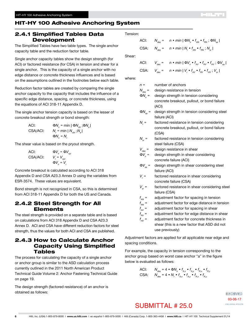
HIT-HY 100 Adhesive Anchoring System
HIT-HY 100 Adhesive Anchoring System
6 Hilti Inc (USA) 1-800-879-8000 I wwwushilticom I en espantildeol 1-800-879-5000 I Hilti (Canada) Corp 1-800-363-4458 I wwwhiltica I HIT-HY 100 Technical Supplement 0114
241 Simplified Tables Data Development
The Simplified Tables have two table types The single anchor capacity table and the reduction factor table
Single anchor capacity tables show the design strength (for ACI) or factored resistance (for CSA) in tension and shear for a single anchor This is the capacity of a single anchor with no edge distance or concrete thickness influences and is based on the assumptions outlined in the footnotes below each table
Reduction factor tables are created by comparing the single anchor capacity to the capacity that includes the influence of a specific edge distance spacing or concrete thickness using the equations of ACI 318-11 Appendix D
The single anchor tension capacity is based on the lesser of concrete breakout strength or bond strength
ACI ФNn = min | ФNcb ФNa | CSAACI Nr = min | Ncbr Na |
ФNn = Nr
The shear value is based on the pryout strength
ACI ФVn = ФVcp CSAACI Vr = Vcpr
ФVn = Vr
Concrete breakout is calculated according to ACI 318 Appendix D and CSA A233 Annex D using the variables from ESR-3574 These values are equivalent
Bond strength is not recognized in CSA so this is determined from ACI 318-11 Appendix D for both the US and Canada
242 Steel Strength for All Elements
The steel strength is provided on a separate table and is based on calculations from ACI 318 Appendix D and CSA A233 Annex D ACI and CSA have different reduction factors for steel strength thus the values for both ACI and CSA are published
243 How to Calculate Anchor Capacity Using Simplified Tables
The process for calculating the capacity of a single anchor or anchor group is similar to the ASD calculation process currently outlined in the 2011 North American Product Technical Guide Volume 2 Anchor Fastening Technical Guide on page 19
The design strength (factored resistance) of an anchor is obtained as follows
Tension
ACI Ndes = n bull min | ФNn bull fAN bull fRN ФNsa |
CSA Ndes = n bull min | Nr bull fAN bull fRN Nsr |
Shear
ACI Vdes = n bull min | ФVn bull fAV bull fRV bull fHV ФVsa |
CSA Vdes = n bull min | Vr bull fAV bull fRV bull fHV Vsr |
where
n = number of anchorsNdes = design resistance in tension
ФNn = design strength in tension considering concrete breakout pullout or bond failure (ACI)
ФNsa = design strength in tension considering steel failure (ACI)
Nr = factored resistance in tension considering concrete breakout pullout or bond failure (CSA)
Nsr = factored resistance in tension considering steel failure (CSA)
Vdes = design resistance in shear ФVn = design strength in shear considering
concrete failure (ACI) ФVsa = design strength in shear considering steel
failure (ACI)Vr = factored resistance in shear considering
concrete failure (CSA)Vsr = factored resistance in shear considering steel
failure (CSA)fAN = adjustment factor for spacing in tensionfRN = adjustment factor for edge distance in tensionfAV = adjustment factor for spacing in shearfRV = adjustment factor for edge distance in shearfHV = adjustment factor for concrete thickness in
shear (this is a new factor that ASD did not use previously)
Adjustment factors are applied for all applicable near edge and spacing conditions
For example the capacity in tension corresponding to the anchor group based on worst case anchor ldquoardquo in the figure below is evaluated as follows
ACI Ndes = 4 bull ФNn bull fAx bull fAy bull fRx bull fRy
CSA Ndes = 4 bull Nr bull fAx bull fAy bull fRx bull fRy
SUBMITTAL 25003-06-17
HIT-HY 100 Adhesive Anchoring System
HIT-HY 100 Adhesive Anchoring System
7Hilti Inc (USA) 1-800-879-8000 I wwwushilticom I en espantildeol 1-800-879-5000 I Hilti (Canada) Corp 1-800-363-4458 I wwwhiltica I HIT-HY 100 Technical Supplement 0114
Note designs are for orthogonal anchor bolt patterns and no reduction factor for the diagonally located adjacent anchor is required
Where anchors are loaded simultaneously in tension and shear interaction must be considered The interaction equation is as follows
Nua Vua ACI ____ + ____ le 12Ndes Vdes
Nf Vf CSA ____ + ____ le 12 Ndes Vdes
where
Nua = Required strength in tension based on factored load combinations of ACI 318 Chapter 9
Vua = Required strength in shear based on factored load combinations of ACI 318 Chapter 9
Nf = Required strength in tension based on factored load combinations of CSA A233 Chapter 8
Vf = Required strength in shear based on factored load combinations of CSA A233 Chapter 8
The full tension strength can be permitted if Vua ACI _____ le 02 Vdes
Vf CSA ____ le 02Vdes
The full shear strength can be permitted if Nua ACI ____ le 02Ndes
Nf CSA ____ le 02Ndes
244 Allowable Stress Design (ASD)
The values of Ndes and Vdes developed from Section 243 are design strengths (factored resistances) and are to be compared to the required strength in tension and shear from factored load combinations of ACI 318 Chapter 9 or CSA A233 Chapter 8
The design strength (factored resistance) can be converted to an ASD value as follows
NdesNdesASD = _____
αASD
VdesVdesASD = _____
αASD
whereαASD = Conversion factor calculated as a weighted
average of the load factors for the controlling load combination
An example for the calculation of αASD is as follows
Controlling strength design load combination is 12D + 16L contribution is 30 D 70 L
αASD = 12 x 030 + 16 x 070 = 148
245 Sustained Loads and Overhead Use
Sustained loading is calculated by multiplying the value of ФNn or Nr by 055 and comparing the value to the tension dead load contribution (and any sustained live loads or other loads) of the factored load Edge spacing and concrete thickness influences do not need to be accounted for when evaluating sustained loads
Consideration of sustained loads is based on ACI 318-11 Appendix D Since sustained loading is not addressed in CSA A233 Annex D it is reasonable to use this approach for CSA based designs
246 Accuracy of the Simplified Tables
Calculations using the Simplified Tables have the potential of providing a design strength (factored resistance) that is exactly what would be calculated using equations from ACI 318 Appendix D or CSA A233 Annex D
The tables for the single anchor design strength (factored resistance) for concrete bond pullout failure or steel failure have the same values that will be computed using the provisions of ACI and CSA
The load adjustment factors for edge distance influences are SUBMITTAL 250
03-06-17
HIT-HY 100 Adhesive Anchoring System
HIT-HY 100 Adhesive Anchoring System
8 Hilti Inc (USA) 1-800-879-8000 I wwwushilticom I en espantildeol 1-800-879-5000 I Hilti (Canada) Corp 1-800-363-4458 I wwwhiltica I HIT-HY 100 Technical Supplement 0114
based on a single anchor near an edge The load adjustment factors for spacing are determined from the influence of two adjacent anchors Each reduction factor is calculated for the minimum value of either concrete or bond failure When more than one edge distance andor spacing condition exists the load adjustment factors are multiplied together This will result in a conservative design when compared to a full calculation based on ACI or CSA Additionally if the failure mode in the single anchor tables is controlled by concrete failure and the reduction factor is controlled by bond failure this will also give a conservative value (and vice versa)
The following is a general summary of the accuracy of the simplified tables
bull Single anchor tables have values equivalent to acalculation according to ACI or CSA
bull Since the table values including load adjustment factorsare calculated using equations that are not linear linearinterpolation is not permitted Use the smaller of the twotable values listed This provides a conservative valueif the application falls between concrete compressivestrengths embedment depths or spacing edgedistance and concrete thickness
bull For one anchor near one edge applying the edgedistance factor typically provides accurate valuesprovided the failure mode of the table values is thesame If the failure mode is not the same the values areconservative
bull For two to four anchors in tension with no edgereductions applying the spacing factors provides a valuethat is equivalent to the ACI and CSA calculated valuesprovided the controlling failure modes of the table valuesare the same If the failure mode is not the same thevalues are conservative
bull The spacing factor in shear is conservative whencompared to two anchors with no edge distanceconsiderations This factor is based on spacing nearan edge and can be conservative for installations awayfrom the edge of the concrete member Note for lessconservative results it is possible to use the spacingfactor in tension for this application if there is no edgedistance to consider
bull The concrete thickness factor in shear is conservativewhen compared to an anchor with no edge influencesThis factor is based on applications near an edge In themiddle of a concrete member this is conservative Notefor less conservative results this factor can be ignored ifthe application is not near an edge
bull The load adjustment factors are determined bycalculations according to ACI 318-11 Appendix D This ismore conservative than ACI 318-08 Appendix D becausethe ψ
gNa factor which is always greater than or equal to10 does not need to be calculated
IMPORTANT NOTE
For applications such as a four bolt or six bolt anchor pattern in a corner in a thin slab the calculation can be up to 80 conservative when compared to a calculation according to ACI or CSA It is always suggested to perform a calculation by hand using the provisions of ACI and CSA to optimize the design This is especially true when the Simplified Table calculation does not provide a value that satisfies the design requirements The fact that a Simplified Table calculation does not exceed a design load does not mean the HIT-HY 100 Adhesive system will not fulfill the design requirements Additional assistance can be given by your local Hilti representative
247 Limitations Using Simplified Tables
There are additional limitations that the Simplified Tables do not consider
bull Load Combinations Table values are meant to be usedwith the load combinations of ACI 318 Section 92 andCSA A233 Chapter 8
bull Supplementary Reinforcement Table values includingreduction factors are based on Condition B which doesnot consider the effects of supplementary reinforcementnor is there an influence factor that can be applied toaccount for supplementary reinforcement
bull Eccentric loading Currently there is not a method forapplying a factor to the tables to account for eccentricloading
bull Moments or Torsion While a designer can apply amoment or torsion to the anchor system and obtain aspecific load per anchor the tables themselves do nothave specific factors to account for moments or torsionapplied to the anchor system
bull Standoff Standoff is not considered in the steel designtables
bull Anchor layout The Simplified Tables assume anorthogonal layout
There may be additional applications not noted above Contact Hilti with any questions for specific applications
SUBMITTAL 25003-06-17
HIT-HY 100 Adhesive Anchoring System
HIT-HY 100 Adhesive Anchoring System
9Hilti Inc (USA) 1-800-879-8000 I wwwushilticom I en espantildeol 1-800-879-5000 I Hilti (Canada) Corp 1-800-363-4458 I wwwhiltica I HIT-HY 100 Technical Supplement 0114
248 Hilti HIT-HY 100 Adhesive with Deformed Reinforcing Bars (Rebar)
Rebar Installation Conditions
Perm
issi
ble
Con
cret
e C
ondi
tions
UncrackedConcrete
DryConcrete
Perm
issi
ble
Dril
ling
Met
hod
Hammer Drilling with Carbide Tipped Drill Bit Water Saturated
Concrete
US Rebar Installation Specifications
RebarSize
DrillBitDia
StandardEmbedDepth
EmbedDepthRange
MinimumBase
MaterialThickness
oslashdin
hef std
in (mm) hef
in (mm) hmin
in (mm)
3 123-38 2-38 ndash 7-12
hef + 1-14(hef + 30)
(86) (60 ndash 191)
4 584-12 2-34 ndash 10(114) (70 ndash 254)
5 345-58 3-18 ndash 12-12
hef + 2d0
(143) (79 ndash 318)
6 786-34 3-12 ndash 15(171) (89 ndash 381)
7 17-78 3-12 ndash 17-12(200) (89 ndash 445)
8 1-189 4 ndash 20
(229) (102 ndash 508)
9 1-3810-18 4-12 ndash 22-12(257) (114 ndash 572)
10 1-1211-14 5 ndash 25(286) (127 ndash 635)
Canadian Rebar Installation Specifications
RebarSize
DrillBitDia
StandardEmbedDepth
EmbedDepthRange
MinimumBase
MaterialThickness
oslashdin
hef std
mm hef
mm hmin
mm10 M 916 115 70 ndash 226 hef + 3015 M 34 145 80 ndash 320
hef + 2d0
20 M 1 200 90 ndash 39025 M 1-14 230 101 ndash 50430 M 1-12 260 120 ndash 598
SUBMITTAL 25003-06-17
HIT-HY 100 Adhesive Anchoring System
HIT-HY 100 Adhesive Anchoring System
10 Hilti Inc (USA) 1-800-879-8000 I wwwushilticom I en espantildeol 1-800-879-5000 I Hilti (Canada) Corp 1-800-363-4458 I wwwhiltica I HIT-HY 100 Technical Supplement 0114
Table 1 mdash Hilti HIT-HY 100 Adhesive Design Strength (Factored Resistance) with Concrete Bond Failure for US Rebar in Uncracked Concrete 12345678
NominalRebar Size
EffectiveEmbedment
Depthin (mm)
Tension mdash ϕNn or Nr Shear mdash ϕVn or Vr
f´c = 2500 psi (172 Mpa)
lb (kN)
f´c = 3000 psi (207 Mpa)
lb (kN)
f´c = 4000 psi (276 Mpa)
lb (kN)
f´c = 6000 psi (414 Mpa)
lb (kN)
f´c = 2500 psi (172 Mpa)
lb (kN)
f´c = 3000 psi (207 Mpa)
lb (kN)
f´c = 4000 psi (276 Mpa)
lb (kN)
f´c = 6000 psi (414 Mpa)
lb (kN)
3
3-38 3155 3155 3155 3340 6790 6790 6790 7200(86) (140) (140) (140) (149) (302) (302) (302) (320)
4-12 4205 4205 4205 4455 9055 9055 9055 9600(114) (187) (187) (187) (198) (403) (403) (403) (427)7-12 7005 7005 7005 7425 15090 15090 15090 15995(191) (312) (312) (312) (330) (671) (671) (671) (711)
4
4-12 5605 5605 5605 5940 12075 12075 12075 12800(114) (249) (249) (249) (264) (537) (537) (537) (569)
6 7475 7475 7475 7920 16100 16100 16100 17065(152) (333) (333) (333) (352) (716) (716) (716) (759)10 12455 12455 12455 13205 26830 26830 26830 28440
(254) (554) (554) (554) (587) (1193) (1193) (1193) (1265)
5
5-58 8760 8760 8760 9285 18865 18865 18865 19995(143) (390) (390) (390) (413) (839) (839) (839) (889)7-12 11680 11680 11680 12380 25150 25150 25150 26660(191) (520) (520) (520) (551) (1119) (1119) (1119) (1186)
12-12 19465 19465 19465 20630 41920 41920 41920 44435(318) (866) (866) (866) (918) (1865) (1865) (1865) (1977)
6
6-34 12610 12610 12610 13370 27165 27165 27165 28795(171) (561) (561) (561) (595) (1208) (1208) (1208) (1281)
9 16815 16815 16815 17825 36220 36220 36220 38395(229) (748) (748) (748) (793) (1611) (1611) (1611) (1708)15 28025 28025 28025 29710 60365 60365 60365 63990
(381) (1247) (1247) (1247) (1322) (2685) (2685) (2685) (2846)
7
7-78 17165 17165 17165 18195 36975 36975 36975 39190(200) (764) (764) (764) (809) (1645) (1645) (1645) (1743)
10-12 22890 22890 22890 24260 49300 49300 49300 52255(267) (1018) (1018) (1018) (1079) (2193) (2193) (2193) (2324)
17-12 38150 38150 38150 40435 82165 82165 82165 87095(445) (1697) (1697) (1697) (1799) (3655) (3655) (3655) (3874)
8
9 21060 22420 22420 23765 45360 48295 48295 51190(229) (937) (997) (997) (1057) (2018) (2148) (2148) (2277)12 29895 29895 29895 31690 64390 64390 64390 68255
(305) (1330) (1330) (1330) (1410) (2864) (2864) (2864) (3036)20 49825 49825 49825 52815 107315 107315 107315 113755
(508) (2216) (2216) (2216) (2349) (4774) (4774) (4774) (5060)
9
10-18 24010 24010 24010 25450 54125 59290 61120 64785(257) (1068) (1068) (1068) (1132) (2408) (2637) (2719) (2882)
13-12 32015 32015 32015 33935 81495 81495 81495 86385(343) (1424) (1424) (1424) (1509) (3625) (3625) (3625) (3843)
22-12 53360 53360 53360 56560 135825 135825 135825 143970(572) (2374) (2374) (2374) (2516) (6042) (6042) (6042) (6404)
10
11-14 29430 29645 29645 31425 63395 69445 75455 79985(286) (1309) (1319) (1319) (1398) (2820) (3089) (3356) (3558)15 39525 39525 39525 41895 97600 100610 100610 106645
(381) (1758) (1758) (1758) (1864) (4341) (4475) (4475) (4744)25 65875 65875 65875 69830 167685 167685 167685 177745
(635) (2930) (2930) (2930) (3106) (7459) (7459) (7459) (7906)
1 See Section 24 for explanation on development of load values2 See Section 244 to convert design strength (factored resistance) value to ASD value3 Linear interpolation between embedment depths and concrete compressive strengths is not permitted4 Apply spacing edge distance and concrete thickness factors in tables 3 - 10 as necessary Compare to the steel values in table 2
The lesser of the values is to be used for the design5 Data is for temperature range A Max short term temperature = 104deg F (40deg C) max long term temperature = 75deg F (24deg C)
For temperature range B Max short term temperature = 176deg F (80deg C) max long term temperature = 122deg F (50deg C) multiply above value by 083 For temperature range C Max short term temperature = 248deg F (120deg C) max long term temperature = 162deg F (72deg C) multiply above value by 048 Short term elevated concrete temperatures are those that occur over brief intervals eg as a result of diurnal cycling Long term concrete temperatures are roughly constant over significant periods of time
6 Tabular values are for dry and water-saturated concrete conditions7 Tabular values are for short term loads only For sustained loads including overhead use see Section 2458 Tabular values are for normal weight concrete only For lightweight concrete multiply design strength (factored resistance) by λa as follows
For sand-lightweight λa = 051 For all-lightweight λa = 045
SUBMITTAL 25003-06-17
HIT-HY 100 Adhesive Anchoring System
HIT-HY 100 Adhesive Anchoring System
11Hilti Inc (USA) 1-800-879-8000 I wwwushilticom I en espantildeol 1-800-879-5000 I Hilti (Canada) Corp 1-800-363-4458 I wwwhiltica I HIT-HY 100 Technical Supplement 0114
Table 2 mdash Steel Design Strength (ACI 318 Appendix D Based Design) for US Rebar 3
NominalRebar Size
ASTM A 615 Grade 40 4 ASTM A 615 Grade 60 4 ASTM A 706 Grade 60 4 Tensile1
ϕNsa
lb (kN)
Shear2
ϕVsa
lb (kN)
Tensile1
ϕNsa
lb (kN)
Shear2
ϕVsa
lb (kN)
Tensile1
ϕNsa
lb (kN)
Shear2
ϕVsa
lb (kN)
34290 2375 6435 3565 6600 3430(191) (106) (286) (159) (294) (153)
47800 4320 11700 6480 12000 6240(347) (192) (520) (288) (534) (278)
512090 6695 18135 10045 18600 9670(538) (298) (807) (447) (827) (430)
617160 9505 25740 14255 26400 13730(763) (423) (1145) (634) (1174) (611)
723400 12960 35100 19440 36000 18720(1041) (576) (1561) (865) (1601) (833)
830810 17065 46215 25595 47400 24650(1370) (759) (2056) (1139) (2108) (1096)
939000 21600 58500 32400 60000 31200(1735) (961) (2602) (1441) (2669) (1388)
1049530 27430 74295 41150 76200 39625(2203) (1220) (3305) (1830) (3390) (1763)
1 Tensile = ϕ AseN futa as noted in ACI 318 Appendix D2 Shear = ϕ 060 AseN futa as noted in ACI 318 Appendix D3 See Section 244 to convert design strength (factored resistance) value to ASD value4 ASTM A706 Grade 60 rebar are considered ductile steel elements ASTM A 615 Grade 40 and 60 rebar are considered brittle steel elements
Table 3 mdash Load Adjustment Factors for 3 US Rebar in Uncracked Concrete 12
3Uncracked Concrete
Spacing Factor in Tension
fAN
Edge Distance Factor in Tension
fRN
Spacing Factor in Shear3
fAV
Edge Distance in ShearConc Thickness Factor in Shear4
fHV
Toward Edge
fRV
To Edge
fRV
Embedment hef in (mm)
3-38 4-12 7-12 3-38 4-12 7-12 3-38 4-12 7-12 3-38 4-12 7-12 3-38 4-12 7-12 3-38 4-12 7-12(86) (114) (191) (86) (114) (191) (86) (114) (191) (86) (114) (191) (86) (114) (191) (86) (114) (191)
Spac
ing
(s)
Edg
e D
ista
nce
(ca)
Con
cret
e Th
ickn
ess
(h)
mdash in
(mm
)
1-34 (44) na na na 032 023 013 na na na 011 008 005 022 016 010 na na na1-78 (48) 059 057 054 033 024 014 054 053 052 012 009 005 024 018 011 na na na
2 (51) 060 057 054 034 025 014 054 054 053 013 010 006 027 020 012 na na na3 (76) 065 061 057 043 031 018 057 055 054 024 018 011 046 037 022 na na na
3-58 (92) 068 063 058 049 036 021 058 056 055 032 024 015 052 042 029 na na na4 (102) 070 065 059 053 038 022 059 057 055 038 028 017 055 045 034 na na na
4-58 (117) 073 067 060 060 044 025 060 058 056 047 035 021 062 049 036 063 na na5 (127) 075 069 061 065 048 028 061 059 056 052 039 024 065 051 037 066 na na
5-34 (146) 078 071 063 075 055 032 062 060 057 065 048 029 075 057 040 071 064 na6 (152) 080 072 063 078 057 033 063 061 058 069 052 031 078 059 041 072 066 na7 (178) 085 076 066 091 067 039 065 063 059 087 065 039 091 067 045 078 071 na8 (203) 090 080 068 100 076 044 067 064 060 100 080 048 100 076 048 083 076 na
8-34 (222) 093 082 069 083 048 069 066 061 091 055 083 051 087 079 0679 (229) 094 083 070 086 050 070 066 061 095 057 086 052 088 080 068
10 (254) 099 087 072 095 055 072 068 063 100 067 095 057 093 085 07111 (279) 100 091 074 100 061 074 070 064 077 100 061 098 089 07512 (305) 094 077 066 076 071 065 088 066 100 093 07814 (356) 100 081 077 080 075 068 100 077 100 08416 (406) 086 088 085 079 070 088 09018 (457) 090 099 089 082 073 099 09624 (610) 100 100 100 093 081 100 10030 (762) 100 08836 (914) 096
gt48 (1219) 1001 Linear interpolation not permitted2 Shaded area with reduced edge distance is permitted provided rebar has no installation torque3 Spacing factor reduction in shear fAV assumes an influence of a nearby edge If no edge exists then fAV = fAN4 Concrete thickness reduction factor in shear fHV assumes an influence of a nearby edge If no edge exists then fHV = 10
SUBMITTAL 25003-06-17
HIT-HY 100 Adhesive Anchoring System
HIT-HY 100 Adhesive Anchoring System
12 Hilti Inc (USA) 1-800-879-8000 I wwwushilticom I en espantildeol 1-800-879-5000 I Hilti (Canada) Corp 1-800-363-4458 I wwwhiltica I HIT-HY 100 Technical Supplement 0114
Table 4 mdash Load Adjustment Factors for 4 US Rebar in Uncracked Concrete 12
4Uncracked Concrete
Spacing Factor in Tension
fAN
Edge Distance Factor in Tension
fRN
Spacing Factor in Shear3
fAV
Edge Distance in ShearConc Thickness Factor in Shear4
fHV
Toward Edge
fRV
To Edge
fRV
Embedment hef in (mm)
4-12 6 10 4-12 6 10 4-12 6 10 4-12 6 10 4-12 6 10 4-12 6 10(114) (152) (254) (114) (152) (254) (114) (152) (254) (114) (152) (254) (114) (152) (254) (114) (152) (254)
Spac
ing
(s)
Edg
e D
ista
nce
(ca)
Con
cret
e Th
ickn
ess
(h)
mdash in
(mm
) 1-34 (44) na na na 027 020 012 na na na 007 005 003 014 011 006 na na na2-12 (64) 059 057 054 032 023 014 054 053 052 012 009 005 024 018 011 na na na
3 (76) 061 058 055 035 026 015 055 054 053 016 012 007 032 024 014 na na na4 (102) 065 061 057 042 030 018 057 055 054 024 018 011 045 037 022 na na na5 (127) 069 064 058 049 036 021 058 057 055 034 026 015 051 042 031 na na na
5-34 (146) 071 066 060 055 040 023 059 058 055 042 031 019 057 046 034 061 na na6 (152) 072 067 060 057 042 024 060 058 056 045 034 020 059 047 035 062 na na7 (178) 076 069 062 067 049 029 061 059 057 056 042 025 067 052 038 067 na na
7-14 (184) 077 070 062 069 051 030 062 060 057 059 045 027 069 053 038 069 062 na8 (203) 080 072 063 076 056 033 063 061 058 069 052 031 076 057 040 072 066 na9 (229) 083 075 065 086 063 037 065 062 059 082 062 037 086 063 043 076 069 na
10 (254) 087 078 067 095 070 041 066 063 060 096 072 043 095 070 046 081 073 na11-14 (286) 092 081 069 100 078 046 068 065 061 100 086 052 100 078 050 086 078 066
12 (305) 094 083 070 084 049 070 066 061 095 057 084 052 088 080 06814 (356) 100 089 073 098 057 073 069 063 100 072 098 058 095 087 07316 (406) 094 077 100 065 076 071 065 088 100 065 100 093 07818 (457) 100 080 073 079 074 067 100 073 098 08320 (508) 083 082 083 077 069 082 100 08722 (559) 087 090 086 080 071 090 09224 (610) 090 098 089 082 073 098 09630 (762) 100 100 099 090 079 100 10036 (914) 100 098 084
gt48 (1219) 100 096
1 Linear interpolation not permitted2 Shaded area with reduced edge distance is permitted provided rebar has no installation torque3 Spacing factor reduction in shear fAV assumes an influence of a nearby edge If no edge exists then fAV = fAN4 Concrete thickness reduction factor in shear fHV assumes an influence of a nearby edge If no edge exists then fHV = 10
Table 5 mdash Load Adjustment Factors for 5 US Rebar in Uncracked Concrete 12
5Uncracked Concrete
Spacing Factor in Tension
fAN
Edge Distance Factor in Tension
fRN
Spacing Factor in Shear3
fAV
Edge Distance in ShearConc Thickness Factor in Shear4
fHV
Toward Edge
fRV
To Edge
fRV
Embedment hef in (mm)
5-58 7-12 12-12 5-58 7-12 12-12 5-58 7-12 12-12 5-58 7-12 12-12 5-58 7-12 12-12 5-58 7-12 12-12(143) (191) (318) (143) (191) (318) (143) (191) (318) (143) (191) (318) (143) (191) (318) (143) (191) (318)
Spac
ing
(s)
Edg
e D
ista
nce
(ca)
Con
cret
e Th
ickn
ess
(h)
mdash in
(mm
)
1-34 (44) na na na 025 019 011 na na na 005 004 002 010 008 005 na na na3-18 (79) 059 057 054 032 023 014 054 053 052 012 009 005 024 018 011 na na na
4 (102) 062 059 055 036 027 016 055 054 053 017 013 008 035 026 016 na na na4-58 (117) 064 060 056 039 029 017 056 055 054 022 016 010 043 033 020 na na na
5 (127) 065 061 057 041 030 018 057 055 054 024 018 011 045 037 022 na na na6 (152) 068 063 058 047 034 020 058 056 055 032 024 014 050 041 029 na na na7 (178) 071 066 059 053 039 023 059 058 055 040 030 018 055 045 034 na na na
7-18 (181) 071 066 060 054 040 023 059 058 055 041 031 019 056 046 034 061 na na8 (203) 074 068 061 061 045 026 060 059 056 049 037 022 061 049 036 065 na na9 (229) 077 070 062 068 050 029 062 060 057 059 044 026 068 053 038 068 062 na
10 (254) 080 072 063 076 056 033 063 061 058 069 052 031 076 057 040 072 066 na11 (279) 083 074 065 083 061 036 064 062 058 079 060 036 083 062 042 076 069 na12 (305) 086 077 066 091 067 039 066 063 059 091 068 041 091 067 045 079 072 na14 (356) 091 081 069 100 078 046 068 065 061 100 086 051 100 078 049 085 078 06516 (406) 097 086 071 089 052 071 067 062 100 063 089 054 091 083 07018 (457) 100 090 074 100 059 073 069 064 075 100 059 097 088 07420 (508) 094 077 065 076 071 065 088 065 100 093 07822 (559) 099 079 072 079 074 067 100 072 097 08224 (610) 100 082 078 081 076 068 078 100 08626 (660) 085 085 084 078 070 085 08928 (711) 087 091 086 080 071 091 09230 (762) 090 098 089 082 073 098 09636 (914) 098 100 097 089 077 100 100
gt48 (1219) 100 100 100 087
SUBMITTAL 250 03-06-17
HIT-HY 100 Adhesive Anchoring System
HIT-HY 100 Adhesive Anchoring System
13Hilti Inc (USA) 1-800-879-8000 I wwwushilticom I en espantildeol 1-800-879-5000 I Hilti (Canada) Corp 1-800-363-4458 I wwwhiltica I HIT-HY 100 Technical Supplement 0114
Table 6 mdash Load Adjustment Factors for 6 US Rebar in Uncracked Concrete 12
6Uncracked Concrete
Spacing Factor in Tension
fAN
Edge Distance Factor in Tension
fRN
Spacing Factor in Shear3
fAV
Edge Distance in Shear Conc Thickness Factor in Shear4
fHV
Toward Edge
fRV
To Edge
fRV
Embedment hef in (mm)
6-34 9 15 6-34 9 15 6-34 9 15 6-34 9 15 6-34 9 15 6-34 9 15(171) (229) (381) (171) (229) (381) (171) (229) (381) (171) (229) (381) (171) (229) (381) (171) (229) (381)
Spac
ing
(s)
Edg
e D
ista
nce
(ca)
Con
cret
e Th
ickn
ess
(h)
mdash in
(mm
)
1-34 (44) na na na 024 018 010 na na na 004 003 002 008 006 003 na na na3-34 (95) 059 057 054 032 023 014 054 053 052 012 009 005 024 018 011 na na na
4 (102) 060 057 054 033 024 014 054 054 053 013 010 006 026 019 012 na na na5 (127) 062 059 056 037 027 016 055 054 053 018 014 008 036 027 016 na na na
5-14 (133) 063 060 056 038 028 016 056 055 053 020 015 009 039 029 018 na na na6 (152) 065 061 057 041 030 018 056 055 054 024 018 011 045 036 021 na na na7 (178) 067 063 058 046 034 020 057 056 054 030 023 014 049 041 027 na na na8 (203) 070 065 059 051 037 022 059 057 055 037 028 017 053 044 033 na na na
8-12 (216) 071 066 059 054 039 023 059 057 055 040 030 018 056 045 034 060 na na9 (229) 072 067 060 057 042 024 060 058 056 044 033 020 058 047 035 062 na na
10 (254) 075 069 061 063 046 027 061 059 056 051 039 023 063 050 037 065 na na10-34 (273) 077 070 062 068 050 029 061 059 057 057 043 026 068 053 038 068 062 na
12 (305) 080 072 063 076 056 033 063 061 058 067 051 030 076 057 040 072 065 na14 (356) 085 076 066 088 065 038 065 062 059 085 064 038 088 065 044 077 070 na16 (406) 090 080 068 100 074 043 067 064 060 100 078 047 100 074 048 083 075 na
16-34 (425) 091 081 069 078 045 068 065 061 083 050 078 049 085 077 06518 (457) 094 083 070 083 049 069 066 061 093 056 083 052 088 080 06720 (508) 099 087 072 093 054 071 068 063 100 065 093 056 092 084 07122 (559) 100 091 074 100 060 074 069 064 075 100 060 097 088 07424 (610) 094 077 065 076 071 065 086 065 100 092 07826 (660) 098 079 071 078 073 066 097 071 096 08128 (711) 100 081 076 080 075 068 100 076 099 08430 (762) 083 081 082 076 069 081 100 08736 (914) 090 098 088 082 073 098 095
gt48 (1219) 100 100 100 092 080 100 100
1 Linear interpolation not permitted2 Shaded area with reduced edge distance is permitted provided rebar has no installation torque3 Spacing factor reduction in shear fAV assumes an influence of a nearby edge If no edge exists then fAV = fAN4 Concrete thickness reduction factor in shear fHV assumes an influence of a nearby edge If no edge exists then fHV = 10
Table 7 mdash Load Adjustment Factors for 7 US Rebar in Uncracked Concrete 12
7Uncracked Concrete
Spacing Factor in Tension
fAN
Edge Distance Factor in Tension
fRN
Spacing Factor in Shear3
fAV
Edge Distance in Shear Conc Thickness Factor in Shear4
fHV
Toward Edge
fRV
To Edge
fRV
Embedment hef in (mm)
7-78 10-12 17-12 7-78 10-12 17-12 7-78 10-12 17-12 7-78 10-12 17-12 7-78 10-12 17-12 7-78 10-12 17-12(200) (267) (445) (200) (267) (445) (200) (267) (445) (200) (267) (445) (200) (267) (445) (200) (267) (445)
Spac
ing
(s)
Edg
e D
ista
nce
(ca)
Con
cret
e Th
ickn
ess
(h)
mdash in
(mm
)
1-34 (44) na na na 023 017 010 na na na 003 002 001 006 004 002 na na na4-38 (111) 059 057 054 032 023 014 054 053 052 011 008 005 022 016 010 na na na
5 (127) 061 058 055 034 025 015 054 054 053 013 010 006 027 020 012 na na na5-12 (140) 062 059 055 036 026 015 055 054 053 015 012 007 031 023 014 na na na
6 (152) 063 060 056 037 028 016 055 054 053 018 013 008 035 026 016 na na na7 (178) 065 061 057 041 030 018 056 055 054 022 017 010 044 033 020 na na na8 (203) 067 063 058 045 033 019 057 056 054 027 020 012 048 040 024 na na na9 (229) 069 064 059 049 036 021 058 056 055 032 024 014 052 043 029 na na na
9-78 (251) 071 066 059 053 039 023 059 057 055 037 028 017 056 045 033 059 na na10 (254) 071 066 060 054 040 023 059 057 055 038 028 017 056 045 034 059 na na11 (279) 073 067 060 059 044 026 060 058 056 044 033 020 060 048 036 062 na na12 (305) 075 069 061 065 048 028 060 059 056 050 037 022 065 051 037 065 na na
12-12 (318) 076 070 062 067 050 029 061 059 056 053 040 024 067 053 038 066 060 na14 (356) 080 072 063 075 055 033 062 060 057 062 047 028 075 057 040 070 063 na16 (406) 084 075 065 086 063 037 064 061 058 076 057 034 086 063 043 075 068 na18 (457) 088 079 067 097 071 042 066 063 059 091 068 041 097 071 047 079 072 na
19-12 (495) 091 081 069 100 077 045 067 064 060 100 077 046 100 077 049 082 075 06320 (508) 092 082 069 079 046 067 064 060 080 048 079 050 083 076 06422 (559) 097 085 071 087 051 069 066 061 092 055 087 053 088 079 06724 (610) 100 088 073 095 056 071 067 062 100 063 095 057 091 083 07026 (660) 091 075 100 060 073 069 063 071 100 061 095 086 07328 (711) 094 077 065 074 070 064 080 065 099 090 07630 (762) 098 079 070 076 072 065 088 070 100 093 07836 (914) 100 084 084 081 076 068 100 084 100 086
gt48 (1219) 096 100 092 084 075 100 099
SUBMITTAL 250 03-06-17
HIT-HY 100 Adhesive Anchoring System
HIT-HY 100 Adhesive Anchoring System
14 Hilti Inc (USA) 1-800-879-8000 I wwwushilticom I en espantildeol 1-800-879-5000 I Hilti (Canada) Corp 1-800-363-4458 I wwwhiltica I HIT-HY 100 Technical Supplement 0114
Table 8 mdash Load Adjustment Factors for 8 US Rebar in Uncracked Concrete 12
8Uncracked Concrete
Spacing Factor in Tension
fAN
Edge Distance Factor in Tension
fRN
Spacing Factor in Shear3
fAV
Edge Distance in Shear Conc Thickness Factor in Shear4
fHV
Toward Edge
fRV
To Edge
fRV
Embedment hef in (mm)
9 12 20 9 12 20 9 12 20 9 12 20 9 12 20 9 12 20(229) (305) (508) (229) (305) (508) (229) (305) (508) (229) (305) (508) (229) (305) (508) (229) (305) (508)
Spac
ing
(s)
Edg
e D
ista
nce
(ca)
Con
cret
e Th
ickn
ess
(h)
mdash in
(mm
)
1-34 (44) na na na 023 017 010 na na na 002 002 001 005 003 002 na na na5 (127) 059 057 054 032 023 014 054 053 052 011 008 005 022 015 009 na na na6 (152) 061 058 055 035 025 015 055 054 053 014 010 006 029 020 012 na na na
6-14 (159) 062 059 055 035 026 015 055 054 053 015 011 006 030 021 013 na na na7 (178) 063 060 056 038 028 016 055 054 053 018 013 008 036 025 015 na na na8 (203) 065 061 057 041 030 018 056 055 053 022 015 009 044 031 019 na na na9 (229) 067 063 058 045 033 019 057 055 054 026 018 011 048 037 022 na na na
10 (254) 069 064 058 048 035 021 058 056 054 031 022 013 051 042 026 na na na11 (279) 070 065 059 052 038 022 058 057 055 035 025 015 055 044 030 na na na
11-14 (286) 071 066 059 053 039 023 059 057 055 037 026 016 055 045 031 058 na na12 (305) 072 067 060 057 042 024 059 057 055 040 028 017 058 047 034 060 na na13 (330) 074 068 061 061 045 026 060 058 056 046 032 019 062 049 036 063 na na14 (356) 076 069 062 066 049 028 061 058 056 051 036 022 066 052 038 065 na na
14-14 (362) 076 070 062 067 049 029 061 059 056 052 037 022 067 052 038 066 059 na16 (406) 080 072 063 075 055 033 062 060 057 062 044 026 075 057 040 070 062 na18 (457) 083 075 065 085 062 037 064 061 058 074 052 031 085 062 043 074 066 na20 (508) 087 078 067 094 069 041 065 062 059 087 061 037 094 069 046 078 069 na22 (559) 091 081 068 100 076 045 067 063 059 100 071 042 100 076 049 082 073 na
22-14 (565) 091 081 069 077 045 067 063 060 072 043 077 049 082 073 06224 (610) 094 083 070 083 049 068 064 060 081 048 083 052 085 076 06426 (660) 098 086 072 090 053 070 066 061 091 054 090 055 089 079 06728 (711) 100 089 073 097 057 071 067 062 100 061 097 058 092 082 06930 (762) 092 075 100 061 073 068 063 068 100 061 095 085 07236 (914) 100 080 073 077 072 065 089 073 100 093 078
gt48 (1219) 090 098 086 079 071 100 098 100 091
1 Linear interpolation not permitted2 Shaded area with reduced edge distance is permitted provided rebar has no installation torque3 Spacing factor reduction in shear fAV assumes an influence of a nearby edge If no edge exists then fAV = fAN4 Concrete thickness reduction factor in shear fHV assumes an influence of a nearby edge If no edge exists then fHV = 10
Table 9 mdash Load Adjustment Factors for 9 US Rebar in Uncracked Concrete 12
9Uncracked Concrete
Spacing Factor in Tension
fAN
Edge Distance Factor in Tension
fRN
Spacing Factor in Shear3
fAV
Edge Distance in Shear Conc Thickness Factor in Shear4
fHV
Toward Edge
fRV
To Edge
fRV
Embedment hef in (mm)
10-18 13-12 22-12 10-18 13-12 22-12 10-18 13-12 22-12 10-18 13-12 22-12 10-18 13-12 22-12 10-18 13-12 22-12(257) (343) (572) (257) (343) (572) (257) (343) (572) (257) (343) (572) (257) (343) (572) (257) (343) (572)
Spac
ing
(s)
Edg
e D
ista
nce
(ca)
Con
cret
e Th
ickn
ess
(h)
mdash in
(mm
)
1-34 (44) na na na 022 016 010 na na na 002 001 001 004 003 002 na na na5-58 (143) 059 057 054 032 023 014 054 053 052 011 007 004 022 014 009 na na na
6 (152) 060 057 054 033 024 014 054 053 052 012 008 005 024 016 010 na na na7 (178) 062 059 055 036 026 015 055 054 053 015 010 006 030 020 012 na na na
7-14 (184) 062 059 055 036 027 016 055 054 053 016 011 006 032 021 013 na na na8 (203) 063 060 056 038 028 017 055 054 053 018 012 007 037 024 015 na na na9 (229) 065 061 057 041 030 018 056 055 053 022 015 009 044 029 018 na na na
10 (254) 066 062 057 045 033 019 057 055 054 026 017 010 048 034 021 na na na11 (279) 068 064 058 048 035 020 057 056 054 030 020 012 051 039 024 na na na12 (305) 070 065 059 051 037 022 058 056 054 034 022 013 054 044 027 na na na
12-78 (327) 071 066 060 054 040 023 059 057 055 038 025 015 056 046 030 059 na na13 (330) 071 066 060 055 040 024 059 057 055 038 025 015 057 046 030 059 na na14 (356) 073 067 060 059 043 025 059 057 055 043 028 017 060 048 034 061 na na16 (406) 076 070 062 067 050 029 061 058 056 052 035 021 067 053 038 066 na na
16-14 (413) 077 070 062 069 050 029 061 058 056 053 035 021 069 053 038 066 058 na18 (457) 080 072 063 076 056 033 062 059 057 062 041 025 076 057 040 070 061 na20 (508) 083 075 065 084 062 036 063 060 057 073 048 029 084 062 043 073 064 na22 (559) 086 077 066 093 068 040 065 061 058 084 056 034 093 068 045 077 067 na24 (610) 090 080 068 100 074 043 066 062 059 096 064 038 100 074 048 080 070 na
25-14 (641) 092 081 069 078 046 067 063 059 100 069 041 078 049 083 072 06126 (660) 093 082 069 080 047 068 063 060 072 043 080 050 084 073 06228 (711) 096 085 071 087 051 069 064 060 080 048 087 053 087 076 06430 (762) 099 087 072 093 054 070 065 061 089 053 093 056 090 079 06636 (914) 100 094 077 100 065 074 068 063 100 070 100 065 099 086 073
gt48 (1219) 100 086 087 082 075 068 100 087 100 099 084
SUBMITTAL 250 03-06-17
HIT-HY 100 Adhesive Anchoring System
HIT-HY 100 Adhesive Anchoring System
15Hilti Inc (USA) 1-800-879-8000 I wwwushilticom I en espantildeol 1-800-879-5000 I Hilti (Canada) Corp 1-800-363-4458 I wwwhiltica I HIT-HY 100 Technical Supplement 0114
Table 10 mdash Load Adjustment Factors for 10 US Rebar in Uncracked Concrete 12
10Uncracked Concrete
Spacing Factor in Tension
fAN
Edge Distance Factor in Tension
fRN
Spacing Factor in Shear3
fAV
Edge Distance in ShearConc Thickness Factor in Shear4
fHV
Toward Edge
fRV
To Edge
fRV
Embedment hef in (mm)
11-14 15 25 11-14 15 25 11-14 15 25 11-14 15 25 11-14 15 25 11-14 15 25(286) (381) (635) (286) (381) (635) (286) (381) (635) (286) (381) (635) (286) (381) (635) (286) (381) (635)
Spac
ing
(s)
Edg
e D
ista
nce
(ca)
Con
cret
e Th
ickn
ess
(h)
mdash in
(mm
) 1-34 (44) na na na 022 016 009 na na na 002 001 001 003 002 001 na na na6-14 (159) 059 057 054 032 023 014 054 053 052 011 007 004 022 014 008 na na na
7 (178) 060 058 055 034 025 014 054 053 052 013 008 005 026 017 010 na na na8 (203) 062 059 055 036 027 016 055 054 053 016 010 006 031 020 012 na na na9 (229) 063 060 056 039 028 017 055 054 053 019 012 007 038 024 014 na na na
10 (254) 065 061 057 041 030 018 056 055 053 022 014 008 044 029 017 na na na11 (279) 066 062 057 044 032 019 057 055 053 025 016 010 047 033 019 na na na12 (305) 068 063 058 047 034 020 057 055 054 029 019 011 050 038 022 na na na13 (330) 069 064 059 050 037 021 058 056 054 033 021 012 053 042 025 na na na14 (356) 071 066 059 053 039 023 059 056 054 036 024 014 055 045 028 na na na
14-14 (362) 071 066 060 054 040 023 059 056 055 037 024 014 056 046 028 059 na na15 (381) 072 067 060 057 042 024 059 057 055 040 026 015 058 047 031 060 na na16 (406) 074 068 061 061 045 026 060 057 055 045 029 017 061 049 034 062 na na17 (432) 075 069 061 064 047 028 060 058 055 049 032 018 064 051 037 064 na na18 (457) 077 070 062 068 050 029 061 058 056 053 035 020 068 053 038 066 057 na20 (508) 080 072 063 076 056 033 062 059 056 062 040 024 076 057 040 070 060 na22 (559) 083 074 065 083 061 036 063 060 057 072 047 027 083 062 042 073 063 na24 (610) 086 077 066 091 067 039 065 061 058 082 053 031 091 067 045 076 066 na26 (660) 089 079 067 099 072 042 066 062 058 092 060 035 099 072 047 079 069 na28 (711) 091 081 069 100 078 046 067 063 059 100 067 039 100 078 049 082 071 06030 (762) 094 083 070 083 049 068 064 060 074 043 083 052 085 074 06236 (914) 100 090 074 100 059 072 066 061 098 057 100 059 094 081 068
gt48 (1219) 100 082 078 079 072 065 100 087 078 100 094 078
1 Linear interpolation not permitted2 Shaded area with reduced edge distance is permitted provided rebar has no installation torque3 Spacing factor reduction in shear fAV assumes an influence of a nearby edge If no edge exists then fAV = fAN4 Concrete thickness reduction factor in shear fHV assumes an influence of a nearby edge If no edge exists then fHV = 10
SUBMITTAL 25003-06-17
HIT-HY 100 Adhesive Anchoring System
HIT-HY 100 Adhesive Anchoring System
16 Hilti Inc (USA) 1-800-879-8000 I wwwushilticom I en espantildeol 1-800-879-5000 I Hilti (Canada) Corp 1-800-363-4458 I wwwhiltica I HIT-HY 100 Technical Supplement 0114
Table 11 mdash Hilti HIT-HY 100 Adhesive Factored Resistance with Concrete Bond Failure for Canadian Rebar in Uncracked Concrete 12345678
NominalRebar Size
EffectiveEmbedment
Depthmm
Tension mdash Nr Shear mdash Vr
f´c = 20 MPa
(kN)
f´c = 25 MPa
(kN)
f´c = 30 MPa
(kN)
f´c = 35 MPa
(kN)
f´c = 40 MPa
(kN)
f´c = 20 MPa
(kN)
f´c = 25 MPa
(kN)
f´c = 30 MPa
(kN)
f´c = 35 MPa
(kN)
f´c = 40 MPa
(kN)
10 M115 223 223 223 236 236 480 480 480 509 509180 349 349 349 370 370 751 751 751 797 797226 438 438 438 464 464 944 944 944 1000 1000
15 M145 398 398 398 422 422 857 857 857 909 909250 686 686 686 727 727 1478 1478 1478 1566 1566320 878 878 878 931 931 1892 1892 1892 2005 2005
20 M200 669 669 669 709 709 1441 1441 1441 1527 1527355 1187 1187 1187 1259 1259 2558 2558 2558 2711 2711390 1304 1304 1304 1383 1383 2810 2810 2810 2978 2978
25 M230 994 994 994 1054 1054 2141 2141 2141 2270 2270405 1751 1751 1751 1856 1856 3771 3771 3771 3997 3997504 2179 2179 2179 2309 2309 4692 4692 4692 4974 4974
30 M260 1128 1128 1128 1196 1196 2625 2872 2872 3044 3044455 1975 1975 1975 2093 2093 5026 5026 5026 5328 5328598 2595 2595 2595 2751 2751 6606 6606 6606 7002 7002
1 See Section 24 for explanation on development of load values2 See Section 244 to convert design strength (factored resistance) value to ASD value3 Linear interpolation between embedment depths and concrete compressive strengths is not permitted4 Apply spacing edge distance and concrete thickness factors in tables 13 - 17 as necessary Compare to the steel values in table 12
The lesser of the values is to be used for the design5 Data is for temperature range A Max short term temperature = 104deg F (40deg C) max long term temperature = 75deg F (24deg C)
For temperature range B Max short term temperature = 176deg F (80deg C) max long term temperature = 122deg F (50deg C) multiply above value by 083 For temperature range C Max short term temperature = 248deg F (120deg C) max long term temperature = 162deg F (72deg C) multiply above value by 048 Short term elevated concrete temperatures are those that occur over brief intervals eg as a result of diurnal cycling Long term concrete temperatures are roughly constant over significant periods of time
6 Tabular values are for dry and water-saturated concrete conditions7 Tabular values are for short term loads only For sustained loads including overhead use see Section 2458 Tabular values are for normal weight concrete only For lightweight concrete multiply design strength (factored resistance) by λa as follows
For sand-lightweight λa = 051 For all-lightweight λa = 045
Table 12 mdash Steel Factored Resistance (CSA A233 Annex D Based Design) for Canadian Rebar 3
NominalRebar Size
CSA-G3018 Grade 400 4 Tensile1
Nsr
Shear2
Vsr
10 M 321 17915 M 646 35920 M 961 53625 M 1607 89230 M 2261 1257
1 Tensile = Ase ϕs fut R as noted in CSA A233 Annex D2 Shear = Ase ϕs 060 fut R as noted in CSA A233 Annex D3 See Section 244 to convert factored resistance value to ASD value4 CSA-G3018 Grade 400 rebar are considered brittle steel elements
SUBMITTAL 250 03-06-17
HIT-HY 100 Adhesive Anchoring System
HIT-HY 100 Adhesive Anchoring System
17Hilti Inc (USA) 1-800-879-8000 I wwwushilticom I en espantildeol 1-800-879-5000 I Hilti (Canada) Corp 1-800-363-4458 I wwwhiltica I HIT-HY 100 Technical Supplement 0114
Table 13 mdash Load Adjustment Factors for 10 M Canadian Rebar in Uncracked Concrete 12
10 MUncracked Concrete
Spacing Factor in Tension
fAN
Edge Distance Factor in Tension
fRN
Spacing Factor in Shear3
fAV
Edge Distance in ShearConc Thickness Factor in Shear4
fHV
Toward Edge
fRV
To Edge
fRV
Embedment hef mm
115 180 226 115 180 226 115 180 226 115 180 226 115 180 226 115 180 226
Spac
ing
(s)
Edg
e D
ista
nce
(ca)
Con
cret
e Th
ickn
ess
(h)
mdash in
(mm
)
45 na na na 025 016 012 na na na 008 005 004 016 010 008 na na na50 057 055 054 027 017 013 053 053 052 010 006 005 019 012 010 na na na75 061 057 056 033 020 016 055 054 053 018 011 009 035 022 018 na na na
100 064 059 057 039 024 019 057 055 054 027 017 014 045 035 028 na na na125 068 062 059 047 029 023 059 056 056 038 024 019 051 039 035 na na na150 072 064 061 056 035 028 060 058 057 050 032 025 058 042 037 065 na na175 075 066 063 066 041 032 062 059 058 063 040 032 066 046 040 070 na na200 079 069 065 075 047 037 064 060 059 076 049 039 075 051 043 075 na na225 083 071 067 085 052 041 066 062 060 091 058 046 085 055 047 079 068 na250 086 073 068 094 058 046 067 063 061 100 068 054 094 059 050 083 072 na275 090 075 070 100 064 051 069 064 062 079 063 100 064 053 088 075 070300 093 078 072 070 055 071 066 063 090 071 070 057 091 079 073325 097 080 074 076 060 073 067 064 100 081 076 060 095 082 076350 100 082 076 082 064 074 068 066 090 082 064 099 085 079375 085 078 087 069 076 069 067 100 087 069 100 088 082400 087 079 093 074 078 071 068 093 074 091 084450 092 083 100 083 081 073 070 100 083 096 089500 096 087 092 085 076 072 092 100 094550 100 091 100 088 078 074 100 099600 094 092 081 077 100700 100 099 086 081800 100 091 0861000 100 094
gt1200 100
1 Linear interpolation not permitted2 Shaded area with reduced edge distance is permitted provided rebar has no installation torque3 Spacing factor reduction in shear fAV assumes an influence of a nearby edge If no edge exists then fAV = fAN4 Concrete thickness reduction factor in shear fHV assumes an influence of a nearby edge If no edge exists then fHV = 10
Table 14 mdash Load Adjustment Factors for 15 M Canadian Rebar in Uncracked Concrete 12
15 MUncracked Concrete
Spacing Factor in Tension
fAN
Edge Distance Factor in Tension
fRN
Spacing Factor in Shear3
fAV
Edge Distance in ShearConc Thickness Factor in Shear4
fHV
Toward Edge
fRV
To Edge
fRV
Embedment hef mm
145 250 320 145 250 320 145 250 320 145 250 320 145 250 320 145 250 320
Spac
ing
(s)
Edg
e D
ista
nce
(ca)
Con
cret
e Th
ickn
ess
(h)
mdash in
(mm
)
45 na na na 025 014 011 na na na 005 003 002 011 006 005 na na na75 059 055 054 030 017 013 054 053 052 012 007 005 023 014 011 na na na
100 061 057 055 035 020 015 055 054 053 018 010 008 036 021 016 na na na125 064 058 057 040 023 018 057 055 054 025 015 011 044 029 023 na na na150 067 060 058 045 026 020 058 056 055 033 019 015 049 036 030 na na na175 070 062 059 051 029 022 059 056 055 042 024 019 054 038 034 061 na na200 073 063 060 058 033 026 061 057 056 051 030 023 060 041 036 065 na na225 076 065 062 066 037 029 062 058 057 061 035 028 066 044 038 069 na na250 079 067 063 073 041 032 063 059 058 071 041 032 073 046 040 073 na na275 082 068 064 080 045 035 065 060 059 082 048 037 080 049 042 076 na na300 084 070 066 088 050 038 066 061 059 094 054 042 088 052 044 080 067 na325 087 072 067 095 054 042 067 062 060 100 061 048 095 056 047 083 069 na350 090 073 068 100 058 045 069 063 061 068 053 100 059 049 086 072 066375 093 075 070 062 048 070 064 062 076 059 062 051 089 074 069400 096 077 071 066 051 071 065 063 084 065 066 054 092 077 071450 100 080 073 074 058 074 067 064 100 078 074 058 098 082 075500 083 076 083 064 077 068 066 091 083 064 100 086 079550 087 079 091 070 079 070 067 100 091 070 090 083600 090 081 099 077 082 072 069 099 077 094 087650 093 084 100 083 085 074 070 100 083 098 090700 097 086 090 087 076 072 090 100 094800 100 092 100 093 080 075 100 100
1000 100 100 087 081gt1200 094 088
SUBMITTAL 250
03-06-17
HIT-HY 100 Adhesive Anchoring System
HIT-HY 100 Adhesive Anchoring System
18 Hilti Inc (USA) 1-800-879-8000 I wwwushilticom I en espantildeol 1-800-879-5000 I Hilti (Canada) Corp 1-800-363-4458 I wwwhiltica I HIT-HY 100 Technical Supplement 0114
Table 15 mdash Load Adjustment Factors for 20 M Canadian Rebar in Uncracked Concrete 12
20 MUncracked Concrete
Spacing Factor in Tension
fAN
Edge Distance Factor in Tension
fRN
Spacing Factor in Shear3
fAV
Edge Distance in ShearConc Thickness Factor in Shear4
fHV
Toward Edge
fRV
To Edge
fRV
Embedment hef mm
200 355 390 200 355 390 200 355 390 200 355 390 200 355 390 200 355 390
Spac
ing
(s)
Edg
e D
ista
nce
(ca)
Con
cret
e Th
ickn
ess
(h)
mdash in
(mm
)
45 na na na 021 011 010 na na na 003 002 002 007 004 004 na na na100 058 055 054 028 015 014 054 053 053 011 006 006 023 013 012 na na na125 060 056 055 032 017 016 055 053 053 016 009 008 032 018 016 na na na150 063 057 056 036 019 018 056 054 054 021 012 011 041 024 022 na na na175 065 058 057 039 021 019 057 055 054 027 015 014 045 030 027 na na na200 067 059 059 044 024 022 058 055 055 032 018 017 049 035 033 na na na225 069 061 060 049 026 024 059 056 056 039 022 020 052 037 035 na na na250 071 062 061 054 029 027 060 057 056 045 026 023 056 039 037 na na na275 073 063 062 059 032 029 061 057 057 052 029 027 060 041 038 066 na na300 075 064 063 065 035 032 062 058 058 060 034 031 065 042 040 069 na na325 077 065 064 070 038 035 063 059 058 067 038 034 070 044 042 071 na na350 079 066 065 075 041 037 064 059 059 075 042 038 075 046 044 074 na na375 081 068 066 081 044 040 065 060 059 083 047 043 081 049 046 077 na na400 083 069 067 086 047 043 066 061 060 092 052 047 086 051 047 079 na na450 088 071 069 097 053 048 068 062 061 100 062 056 097 055 051 084 069 067500 092 073 071 100 059 053 070 063 063 072 066 100 059 055 089 073 071550 096 076 074 065 059 072 065 064 083 076 065 059 093 077 074600 100 078 076 070 064 074 066 065 095 086 070 064 097 080 078650 081 078 076 069 076 067 066 100 097 076 069 100 084 081700 083 080 082 074 078 069 068 100 082 074 087 084800 088 084 094 085 081 071 070 094 085 093 090
1000 097 093 100 100 089 077 075 100 100 100 1001200 100 100 097 082 080
gt1500 100 090 088
1 Linear interpolation not permitted2 Shaded area with reduced edge distance is permitted provided rebar has no installation torque3 Spacing factor reduction in shear fAV assumes an influence of a nearby edge If no edge exists then fAV = fAN4 Concrete thickness reduction factor in shear fHV assumes an influence of a nearby edge If no edge exists then fHV = 10
Table 16 mdash Load Adjustment Factors for 25 M Canadian Rebar in Uncracked Concrete 12
25 MUncracked Concrete
Spacing Factor in Tension
fAN
Edge Distance Factor in Tension
fRN
Spacing Factor in Shear3
fAV
Edge Distance in ShearConc Thickness Factor in Shear4
fHV
Toward Edge
fRV
To Edge
fRV
Embedment hef mm
230 405 504 230 405 504 230 405 504 230 405 504 230 405 504 230 405 504
Spac
ing
(s)
Edg
e D
ista
nce
(ca)
Con
cret
e Th
ickn
ess
(h)
mdash in
(mm
)
45 na na na 022 012 010 na na na 002 001 001 005 003 002 na na na125 059 055 054 031 017 014 054 053 052 011 006 005 022 012 010 na na na150 061 056 055 035 019 015 055 053 053 014 008 006 028 016 013 na na na175 063 057 056 038 021 016 055 054 053 018 010 008 036 020 016 na na na200 064 058 057 041 022 018 056 054 054 022 012 010 044 025 020 na na na225 066 059 057 045 024 019 057 055 054 026 015 012 048 030 024 na na na250 068 060 058 048 026 021 058 055 054 030 017 014 052 035 028 na na na275 070 061 059 052 028 023 058 056 055 035 020 016 055 038 032 na na na300 072 062 060 057 031 025 059 056 055 040 023 018 058 040 036 060 na na325 074 063 061 061 034 027 060 057 056 045 026 021 062 041 037 063 na na350 075 064 062 066 036 029 061 057 056 050 029 023 066 043 038 065 na na375 077 065 062 071 039 031 061 058 057 056 032 026 071 045 039 067 na na400 079 066 063 076 041 033 062 058 057 062 035 028 076 047 041 070 na na450 083 069 065 085 046 037 064 059 058 074 042 034 085 050 044 074 na na500 086 071 067 094 052 041 065 060 059 086 049 039 094 054 046 078 064 na550 090 073 068 100 057 045 067 061 060 099 056 045 100 058 049 081 067 na600 093 075 070 062 049 068 062 061 100 064 052 062 052 085 070 066650 097 077 071 067 053 070 063 062 073 058 067 055 089 073 068700 100 079 073 072 058 071 064 063 081 065 072 059 092 076 071750 081 075 077 062 073 066 063 090 072 077 062 095 079 073800 083 076 083 066 074 067 064 099 080 083 066 098 081 076
1000 091 083 100 082 080 071 068 100 100 100 082 100 091 0851200 099 090 099 086 075 071 099 100 093
gt1500 100 100 100 095 081 077 100 100
SUBMITTAL 250
03-06-17
HIT-HY 100 Adhesive Anchoring System
HIT-HY 100 Adhesive Anchoring System
19Hilti Inc (USA) 1-800-879-8000 I wwwushilticom I en espantildeol 1-800-879-5000 I Hilti (Canada) Corp 1-800-363-4458 I wwwhiltica I HIT-HY 100 Technical Supplement 0114
Table 17 mdash Load Adjustment Factors for 30 M Canadian Rebar in Uncracked Concrete 12
30 MUncracked Concrete
Spacing Factor in Tension
fAN
Edge Distance Factor in Tension
fRN
Spacing Factor in Shear3
fAV
Edge Distance in ShearConc Thickness Factor in Shear4
fHV
Toward Edge
fRV
To Edge
fRV
Embedment hef mm
260 455 598 260 455 598 260 455 598 260 455 598 260 455 598 260 455 598
Spac
ing
(s)
Edg
e D
ista
nce
(ca)
Con
cret
e Th
ickn
ess
(h)
mdash in
(mm
)
45 na na na 023 013 009 na na na 002 001 001 004 002 002 na na na150 060 055 054 033 018 014 054 053 052 012 006 005 023 012 009 na na na175 061 056 055 036 020 015 055 053 052 014 008 006 029 015 012 na na na200 063 057 056 039 021 016 055 053 053 018 009 007 035 019 014 na na na225 064 058 056 042 023 017 056 054 053 021 011 008 042 022 017 na na na250 066 059 057 045 025 019 057 054 054 025 013 010 048 026 020 na na na275 068 060 058 048 026 020 057 055 054 029 015 011 051 030 023 na na na300 069 061 058 051 028 021 058 055 054 033 017 013 054 034 026 na na na325 071 062 059 055 030 023 059 056 055 037 019 015 057 038 029 na na na350 072 063 060 059 032 024 059 056 055 041 022 016 060 041 033 061 na na375 074 064 060 063 035 026 060 056 055 045 024 018 063 042 036 063 na na400 076 065 061 067 037 028 061 057 056 050 026 020 067 044 037 065 na na450 079 066 063 076 042 031 062 058 056 060 031 024 076 047 040 069 na na500 082 068 064 084 046 035 063 059 057 070 037 028 084 050 042 072 na na550 085 070 065 092 051 038 064 059 058 081 042 032 092 054 044 076 061 na600 088 072 067 100 055 042 066 060 059 092 048 037 100 057 047 079 064 na650 092 074 068 060 045 067 061 059 100 054 041 061 049 083 067 na700 095 076 070 065 049 068 062 060 061 046 065 052 086 069 063750 098 077 071 069 052 070 063 061 067 051 069 054 089 072 065800 100 079 072 074 055 071 064 061 074 057 074 057 092 074 068900 083 075 083 062 074 065 063 089 067 083 062 097 078 072
1000 087 078 092 069 076 067 064 100 079 092 069 100 083 0751200 094 083 100 083 082 071 067 100 100 083 091 083
gt1500 100 092 100 089 076 071 100 100 092
1 Linear interpolation not permitted2 Shaded area with reduced edge distance is permitted provided rebar has no installation torque3 Spacing factor reduction in shear fAV assumes an influence of a nearby edge If no edge exists then fAV = fAN4 Concrete thickness reduction factor in shear fHV assumes an influence of a nearby edge If no edge exists then fHV = 10
SUBMITTAL 25003-06-17
HIT-HY 100 Adhesive Anchoring System
HIT-HY 100 Adhesive Anchoring System
20 Hilti Inc (USA) 1-800-879-8000 I wwwushilticom I en espantildeol 1-800-879-5000 I Hilti (Canada) Corp 1-800-363-4458 I wwwhiltica I HIT-HY 100 Technical Supplement 0114
249 Hilti HIT-HY 100 Adhesive with Hilti HAS Threaded Rod
Hilti HAS Threaded Rod Installation Conditions
Perm
issi
ble
Con
cret
e C
ondi
tions
UncrackedConcrete
DryConcrete
Perm
issi
ble
Dril
ling
Met
hod
Hammer Drilling with Carbide Tipped Drill Bit Water Saturated
Concrete
Mechanical PropertiesHilti HAS Threaded Rod Material Specifications fya Min futa
ksi (MPa) ksi (MPa)Standard HAS-E rod material meets the requirements of ISO 898 Class 58 58 (400) 725 (500)High Strength or lsquoSuper HASrsquo rod material meets the requirements of ASTM A 193 Grade B7 105 (724) 125 (862)Stainless HAS rod material meets the requirements of ASTM F 593 (AISI 304316) Condition CW1 38 to 58
65 (448) 100 (689)
Stainless HAS rod material meets the requirements of ASTM F 593 (AISI 304316) Condition CW 34 to 1-14
45 (310) 85 (586)
HAS Super amp HAS-E Standard Nut Material meets the requirements of SAE J995 Grade 5HAS Stainless Steel Nut material meets the requirements of ASTM F 594HAS Standard and Stainless Steel Washers meet dimensional requirements of ANSI B18221 Type A PlainHAS Stainless Steel Washers meet the requirements of AISI 304 or AISI 316 conforming to ASTM A 240HAS Super amp HAS-E Standard Washers meet the requirements of ASTM F 884 HVAll HAS Super Rods (except 78rdquo) amp HAS-E Standard nuts amp washers are zinc plated to ASTM B 633 SC 178rdquo HAS Super rods hot-dip galvanized in accordance with ASTM A 153HAS Carbon steel HAS rods are furnished with a 0005-mm-thick zinc electroplated coatingNote Special Order threaded rods may vary from standard materials
Hilti HAS Threaded Rod Installation SpecificationsNominal
Rod Diameter
Drill Bit Diameter
Embedment Depth
Embedment Depth Range
Maximum Installation
Torque
Minimum Base Material
Thickness
oslashdin (mm)
oslashd0in
hef stdin (mm)
hefin (mm)
Tmaxft-lb (Nm)
hminin (mm)
38716
3-38 2-38 ndash 7-12 15hef + 1-14 (hef + 30)
(95) (86) (60 ndash 191) (20)12
9164-12 2-34 ndash 10 30
(127) (114) (70 ndash 254) (41)58
345-58 3-18 ndash 12-12 60
hef + 2d0
(159) (143) (79 ndash 318) (81)34
786-34 3-12 ndash 15 100
(191) (171) (89 ndash 381) (136)78
17-78 3-12 ndash 17-12 125
(222) (200) (89 ndash 445) (169)1
1-189 4 ndash 20 150
(254) (229) (102 ndash 508) (203)1-14
1-3811-14 5 ndash 25 200
(318) (286) (127 ndash 635) (271)
min
maxdf HAS 38 12 58 34 78 1 1-14
df1 12 58 1316 1516 1-18 1-14 1-12
df2 716 916 1116 1316 1516 1-18 1-38
Use two washers
SUBMITTAL 25003-06-17
HIT-HY 100 Adhesive Anchoring System
HIT-HY 100 Adhesive Anchoring System
21Hilti Inc (USA) 1-800-879-8000 I wwwushilticom I en espantildeol 1-800-879-5000 I Hilti (Canada) Corp 1-800-363-4458 I wwwhiltica I HIT-HY 100 Technical Supplement 0114
Table 18 mdash Hilti HIT-HY 100 Adhesive Design Strength (Factored Resistance) with Concrete Bond Failure for Fractional Threaded Rod in Uncracked Concrete 12345678
Anchor Diameter in (mm)
Effective Embedment
Depth in (mm)
Tension mdash ФNn or Nr Shear mdash ФVn or Vr
f´c = 2500 psi (172 Mpa)
lb (kN)
f´c = 3000 psi (207 Mpa)
lb (kN)
f´c = 4000 psi (276 Mpa)
lb (kN)
f´c = 6000 psi (414 Mpa)
lb (kN)
f´c = 2500 psi(172 Mpa)
lb (kN)
f´c = 3000 psi(207 Mpa)
lb (kN)
f´c = 4000 psi(276 Mpa)
lb (kN)
f´c = 6000 psi(414 Mpa)
lb (kN)
38(95)
2-38 2765 2765 2765 2930 2975 2975 2975 3155(60) (123) (123) (123) (130) (132) (132) (132) (140)
3-38 3930 3930 3930 4165 8460 8460 8460 8970(86) (175) (175) (175) (185) (376) (376) (376) (399)
4-12 5240 5240 5240 5550 11280 11280 11280 11960(114) (233) (233) (233) (247) (502) (502) (502) (532)7-12 8730 8730 8730 9255 18800 18800 18800 19930(191) (388) (388) (388) (412) (836) (836) (836) (887)
12(127)
2-34 3555 3895 4500 4790 7660 8395 9690 10320(70) (158) (173) (200) (213) (341) (373) (431) (459)
4-12 7395 7395 7395 7840 15935 15935 15935 16890(114) (329) (329) (329) (349) (709) (709) (709) (751)
6 9865 9865 9865 10455 21245 21245 21245 22520(152) (439) (439) (439) (465) (945) (945) (945) (1002)10 16440 16440 16440 17425 35405 35405 35405 37530
(254) (731) (731) (731) (775) (1575) (1575) (1575) (1669)
58(159)
3-18 4310 4720 5450 6675 9280 10165 11740 14380(79) (192) (210) (242) (297) (413) (452) (522) (640)
5-58 10405 11400 12135 12860 22415 24550 26130 27700(143) (463) (507) (540) (572) (997) (1092) (1162) (1232)7-12 16020 16175 16175 17145 34505 34840 34840 36935(191) (713) (719) (719) (763) (1535) (1550) (1550) (1643)
12-12 26960 26960 26960 28580 58070 58070 58070 61555(318) (1199) (1199) (1199) (1271) (2583) (2583) (2583) (2738)
34(191)
3-12 5105 5595 6460 7910 11000 12050 13915 17040(89) (227) (249) (287) (352) (489) (536) (619) (758)
6-34 13680 14985 17305 18630 29460 32275 37265 40125(171) (609) (667) (770) (829) (1310) (1436) (1658) (1785)
9 21060 23070 23430 24840 45360 49690 50470 53500(229) (937) (1026) (1042) (1105) (2018) (2210) (2245) (2380)15 39055 39055 39055 41395 84115 84115 84115 89165
(381) (1737) (1737) (1737) (1841) (3742) (3742) (3742) (3966)
78(222)
3-12 5105 5595 6460 7910 11000 12050 13915 17040(89) (227) (249) (287) (352) (489) (536) (619) (758)
7-78 17235 18885 21245 22520 37125 40670 45765 48510(200) (767) (840) (945) (1002) (1651) (1809) (2036) (2158)
10-12 26540 28330 28330 30030 57160 61015 61015 64680(267) (1181) (1260) (1260) (1336) (2543) (2714) (2714) (2877)
17-12 47215 47215 47215 50050 101695 101695 101695 107795(445) (2100) (2100) (2100) (2226) (4524) (4524) (4524) (4795)
1(254)
4 6240 6835 7895 9665 13440 14725 17000 20820(102) (278) (304) (351) (430) (598) (655) (756) (926)
9 21060 23070 25545 27080 45360 49690 55020 58325(229) (937) (1026) (1136) (1205) (2018) (2210) (2447) (2594)12 32425 34060 34060 36105 69835 73360 73360 77765
(305) (1442) (1515) (1515) (1606) (3106) (3263) (3263) (3459)20 56770 56770 56770 60175 122270 122270 122270 129605
(508) (2525) (2525) (2525) (2677) (5439) (5439) (5439) (5765)
1-14(318)
5 8720 9555 11030 13165 18785 20575 23760 29100(127) (388) (425) (491) (586) (836) (915) (1057) (1294)
11-14 27945 27945 27945 29620 63395 69445 71130 75395(286) (1243) (1243) (1243) (1318) (2820) (3089) (3164) (3354)15 37255 37255 37255 39495 94835 94835 94835 100525
(381) (1657) (1657) (1657) (1757) (4218) (4218) (4218) (4472)25 62095 62095 62095 65820 158060 158060 158060 167545
(635) (2762) (2762) (2762) (2928) (7031) (7031) (7031) (7453)1 See Section 24 for explanation on development of load values2 See Section 244 to convert design strength (factored resistance) value to ASD value3 Linear interpolation between embedment depths and concrete compressive strengths is not permitted4 Apply spacing edge distance and concrete thickness factors in tables 21 - 27 as necessary Compare to the steel values in table 19 or 20
The lesser of the values is to be used for the design5 Data is for temperature range A Max short term temperature = 104deg F (40deg C) max long term temperature = 75deg F (24deg C)
For temperature range B Max short term temperature = 176deg F (80deg C) max long term temperature = 122deg F (50deg C) multiply above value by 077 For temperature range C Max short term temperature = 248deg F (120deg C) max long term temperature = 162deg F (72deg C) multiply above value by 044 Short term elevated concrete temperatures are those that occur over brief intervals eg as a result of diurnal cycling Long term concrete temperatures are roughly constant over significant periods of time
6 Tabular values are for dry concrete conditions For water saturated concrete multiply design strength (factored resistance) by 0857 Tabular values are for short term loads only For sustained loads including overhead use see Section 2458 Tabular values are for normal weight concrete only For lightweight concrete multiply design strength (factored resistance) by λa as follows
For sand-lightweight λa = 051 For all-lightweight λa = 045
SUBMITTAL 250
03-06-17
HIT-HY 100 Adhesive Anchoring System
HIT-HY 100 Adhesive Anchoring System
22 Hilti Inc (USA) 1-800-879-8000 I wwwushilticom I en espantildeol 1-800-879-5000 I Hilti (Canada) Corp 1-800-363-4458 I wwwhiltica I HIT-HY 100 Technical Supplement 0114
Table 19 mdash Steel Design Strength (ACI 318 Appendix D Based Design) for Hilti HAS Threaded Rods 3
AnchorDiameterin (mm)
HAS Standard ISO 898 Class 58 4 HAS-Super ASTM A193 B7 4 HAS SS AISI 304316 SS 4 Tensile1
ϕNsa
lb (kN)
Shear2
ϕVsa
lb (kN)
Tensile1
ϕNsa
lb (kN)
Shear2
ϕVsa
lb (kN)
Tensile1
ϕNsa
lb (kN)
Shear2
ϕVsa
lb (kN)38 3655 1685 7265 3150 5040 2325(95) (163) (75) (323) (140) (224) (103)12 6690 3705 13300 6915 9225 5110
(127) (298) (165) (592) (308) (410) (227)58 10650 5900 21190 11020 14690 8135
(159) (474) (262) (943) (490) (653) (362)34 15765 8730 31360 16305 18480 10235
(191) (701) (388) (1395) (725) (822) (455)78 21755 12050 43285 22505 25510 14125
(222) (968) (536) (1925) (1001) (1135) (628)1 28540 15805 56785 29525 33465 18535
(254) (1270) (703) (2526) (1313) (1489) (824)1-14 45670 25295 90850 47240 53540 29655(318) (2031) (1125) (4041) (2101) (2382) (1319)
1 Tensile = ϕ AseN futa as noted in ACI 318 Appendix D2 Shear = ϕ 060 AseN futa as noted in ACI 318 Appendix D3 See Section 244 to convert design strength (factored resistance) value to ASD value4 HAS Super rods are considered ductile steel elements HAS Standard and HAS SS rods are considered brittle steel elements
Table 20 mdash Steel Factored Resistance (CSA A233 Annex D Based Design) for Hilti HAS Threaded Rods 3
AnchorDiameterin (mm)
HAS Standard ISO 898 Class 58 4 HAS-Super ASTM A193 B7 4 HAS SS AISI 304316 SS 4 Tensile1
ϕNsr
lb (kN)
Shear2
ϕVsr
lb (kN)
Tensile1
ϕNsr
lb (kN)
Shear2
ϕVsr
lb (kN)
Tensile1
ϕNsr
lb (kN)
Shear2
ϕVsr
lb (kN)38 3345 1555 6585 3090 4610 2140(95) (149) (69) (293) (137) (205) (95)12 6125 3410 12060 6785 8445 4705
(127) (272) (152) (536) (302) (376) (209)58 9750 5430 19210 10805 13445 7490
(159) (434) (242) (854) (481) (598) (333)34 14430 8040 28430 15990 16915 9425
(191) (642) (358) (1265) (711) (752) (419)78 19915 11095 39245 22075 23350 13010
(222) (886) (494) (1746) (982) (1039) (579)1 26125 14555 51485 28960 30635 17065
(254) (1162) (647) (2290) (1288) (1363) (759)1-14 41805 23290 82370 46335 49010 27305(318) (1860) (1036) (3664) (2061) (2180) (1215)
1 Tensile = Ase ϕs fut R as noted in CSA A233 Annex D2 Shear = Ase ϕs 060 fut R as noted in CSA A233 Annex D3 See Section 244 to convert design strength (factored resistance) value to ASD value4 HAS Super rods are considered ductile steel elements HAS Standard and HAS SS rods are considered brittle steel elements
SUBMITTAL 25003-06-17
HIT-HY 100 Adhesive Anchoring System
HIT-HY 100 Adhesive Anchoring System
23Hilti Inc (USA) 1-800-879-8000 I wwwushilticom I en espantildeol 1-800-879-5000 I Hilti (Canada) Corp 1-800-363-4458 I wwwhiltica I HIT-HY 100 Technical Supplement 0114
Table 21 mdash Load Adjustment Factors for 38-in Diameter Fractional Threaded Rods in Uncracked Concrete 12
38 inUncracked Concrete
Spacing Factor in Tension
fAN
Edge Distance Factor in Tension
fRN
Spacing Factor in Shear3
fAV
Edge Distance in ShearConc Thickness Factor in Shear4
fHV
Toward Edge
fRV
To Edge
fRV
Embedment hef in (mm)
2-38 3-38 4-12 7-12 2-38 3-38 4-12 7-12 2-38 3-38 4-12 7-12 2-38 3-38 4-12 7-12 2-38 3-38 4-12 7-12 2-38 3-38 4-12 7-12(60) (86) (114) (191) (60) (86) (114) (191) (60) (86) (114) (191) (60) (86) (114) (191) (60) (86) (114) (191) (60) (86) (114) (191)
Spac
ing
(s)
Edg
e D
ista
nce
(ca)
Con
cret
e Th
ickn
ess
(h)
mdash in
(mm
)
1-34 (44) na na na na 040 031 023 013 na na na na 024 009 007 004 047 017 013 008 na na na na1-78 (48) 060 059 057 054 042 032 023 013 057 054 053 052 026 010 007 004 042 019 014 009 na na na na
2 (51) 061 060 057 054 043 033 024 014 057 054 053 052 029 011 008 005 043 021 016 010 na na na na3 (76) 066 065 061 057 056 041 030 017 061 056 055 053 053 020 015 009 056 039 029 018 na na na na
3-58 (92) 070 068 063 058 065 046 034 019 063 057 056 054 070 026 019 012 065 048 039 023 073 na na na4 (102) 072 070 065 059 072 049 036 021 065 057 056 054 082 030 023 014 072 051 041 027 076 na na na
4-58 (117) 075 073 067 060 083 055 040 023 067 059 057 055 100 037 028 017 083 056 045 033 082 059 na na5 (127) 077 075 069 061 090 060 044 025 068 059 058 055 042 032 019 090 060 047 034 085 061 na na
5-34 (146) 081 078 071 063 100 069 050 029 071 061 059 056 052 039 023 100 069 052 037 091 066 060 na6 (152) 082 080 072 063 072 052 030 072 061 059 057 055 041 025 072 054 037 093 067 061 na7 (178) 088 085 076 066 084 061 035 075 063 061 058 070 052 031 084 061 041 100 072 066 na8 (203) 093 090 080 068 096 070 040 079 065 062 059 085 064 038 096 070 044 077 070 na
8-34 (222) 097 093 082 069 100 076 044 082 066 064 060 097 073 044 100 076 047 081 074 0629 (229) 099 094 083 070 078 045 083 067 064 060 100 076 046 078 048 082 075 063
10 (254) 100 099 087 072 087 050 086 069 065 061 089 054 087 052 087 079 06611 (279) 100 091 074 096 055 090 071 067 062 100 062 096 056 091 082 07012 (305) 094 077 100 061 094 072 069 063 070 100 061 095 086 07314 (356) 100 081 071 100 076 072 065 089 071 100 093 07816 (406) 086 081 080 075 068 100 081 099 08418 (457) 090 091 084 078 070 091 100 08924 (610) 100 100 095 087 076 100 10030 (762) 100 096 08336 (914) 100 090
gt48 (1219) 100
1 Linear interpolation not permitted2 Shaded area with reduced edge distance is permitted provided the installation torque is reduced to 030 Tmax for 5d le s le 16-in and to 05 Tmax for s gt 16-in3 Spacing factor reduction in shear fAV assumes an influence of a nearby edge If no edge exists then fAV = fAN4 Concrete thickness reduction factor in shear fHV assumes an influence of a nearby edge If no edge exists then fHV = 10
Table 22 mdash Load Adjustment Factors for 12-in Diameter Fractional Threaded Rods in Uncracked Concrete 12
12 inUncracked Concrete
Spacing Factor in Tension
fAN
Edge Distance Factor in Tension
fRN
Spacing Factor in Shear 3
fAV
Edge Distance in ShearConc Thickness Factor in Shear4
fHV
Toward Edge
fRV
To Edge
fRV
Embedment hef in (mm)
2-34 4-12 6 10 2-34 4-12 6 10 2-34 4-12 6 10 2-34 4-12 6 10 2-34 4-12 6 10 2-34 4-12 6 10(70) (114) (152) (254) (70) (114) (152) (254) (70) (114) (152) (254) (70) (114) (152) (254) (70) (114) (152) (254) (70) (114) (152) (254)
Spac
ing
(s)
Edg
e D
ista
nce
(ca)
Con
cret
e Th
ickn
ess
(h)
mdash in
(mm
) 1-34 (44) na na na na 036 027 020 012 na na na na 010 005 004 002 021 011 008 005 na na na na2-12 (64) 060 059 057 054 043 031 023 013 055 053 053 052 018 009 007 004 035 018 014 008 na na na na
3 (76) 062 061 058 055 048 033 025 014 056 054 053 052 023 012 009 005 046 024 018 011 na na na na4 (102) 066 065 061 057 059 039 029 017 058 055 054 053 036 018 014 008 059 037 028 017 058 na na na5 (127) 070 069 064 058 074 045 033 019 060 057 056 054 050 026 019 012 074 046 038 023 065 na na na
5-34 (146) 073 071 066 060 085 050 037 021 062 058 056 055 061 032 024 014 085 051 041 029 069 056 na na6 (152) 074 072 067 060 088 052 038 022 063 058 057 055 065 034 025 015 088 052 042 031 071 057 na na7 (178) 078 076 069 062 100 060 044 026 065 059 058 056 082 043 032 019 100 060 047 034 077 061 na na
7-14 (184) 079 077 070 062 062 045 026 065 060 058 056 087 045 034 020 062 048 034 078 063 057 na8 (203) 082 080 072 063 068 050 029 067 061 059 056 100 052 039 023 068 051 036 082 066 060 na9 (229) 085 083 075 065 077 056 033 069 062 060 057 062 047 028 077 056 039 087 070 063 na
10 (254) 089 087 078 067 085 062 037 071 064 061 058 073 055 033 085 062 041 092 074 067 na11-14 (286) 094 092 081 069 096 070 041 074 065 063 059 087 065 039 096 070 044 097 078 071 060
12 (305) 097 094 083 070 100 075 044 075 066 063 060 096 072 043 100 075 046 100 081 073 06214 (356) 100 100 089 073 087 051 079 069 066 061 100 091 054 087 052 087 079 06716 (406) 094 077 100 058 083 072 068 063 100 066 100 058 093 084 07118 (457) 100 080 066 088 074 070 064 079 066 099 090 07620 (508) 083 073 092 077 072 066 093 073 100 094 08022 (559) 087 080 096 080 075 067 100 080 099 08424 (610) 090 088 100 082 077 069 088 100 08730 (762) 100 100 091 083 074 100 09836 (914) 099 090 079 100
gt48 (1219) 100 100 088
SUBMITTAL 250
03-06-17
HIT-HY 100 Adhesive Anchoring System
HIT-HY 100 Adhesive Anchoring System
24 Hilti Inc (USA) 1-800-879-8000 I wwwushilticom I en espantildeol 1-800-879-5000 I Hilti (Canada) Corp 1-800-363-4458 I wwwhiltica I HIT-HY 100 Technical Supplement 0114
Table 23 mdash Load Adjustment Factors for 58-in Diameter Fractional Threaded Rods in Uncracked Concrete 12
58 inUncracked Concrete
Spacing Factor in Tension
fAN
Edge Distance Factor in Tension
fRN
Spacing Factor in Shear3
fAV
Edge Distance in ShearConc Thickness Factor in Shear4
fHV
Toward Edge
fRV
To Edge
fRV
Embedment hef in (mm)
3-18 5-58 7-12 12-12 3-18 5-58 7-12 12-12 3-18 5-58 7-12 12-12 3-18 5-58 7-12 12-12 3-18 5-58 7-12 12-12 3-18 5-58 7-12 12-12(79) (143) (191) (318) (79) (143) (191) (318) (79) (143) (191) (318) (79) (143) (191) (318) (79) (143) (191) (318) (79) (143) (191) (318)
Spac
ing
(s)
Edg
e D
ista
nce
(ca)
Con
cret
e Th
ickn
ess
(h)
mdash in
(mm
)
1-34 (44) na na na na 034 025 018 011 na na na na 009 004 003 002 019 008 006 003 na na na na3-18 (79) 060 059 057 054 045 031 022 013 056 054 053 052 022 010 007 004 045 020 013 008 na na na na
4 (102) 062 062 059 055 053 034 025 015 058 055 053 052 032 015 010 006 053 029 019 011 na na na na4-58 (117) 064 064 060 056 060 037 027 016 059 055 054 053 040 018 012 007 060 036 024 014 060 na na na
5 (127) 065 065 061 057 064 039 028 017 060 056 054 053 045 021 013 008 064 039 027 016 063 na na na6 (152) 068 068 063 058 077 043 032 019 062 057 055 054 059 027 018 010 077 044 035 021 069 na na na7 (178) 072 071 066 059 089 048 035 021 064 058 056 054 075 034 022 013 090 049 040 026 074 na na na
7-18 (181) 072 071 066 060 090 049 036 021 064 058 056 054 077 035 023 013 091 049 040 027 075 057 na na8 (203) 075 074 068 061 099 053 039 023 066 059 057 055 091 041 027 016 100 054 043 032 079 061 na na9 (229) 078 077 070 062 100 060 044 026 068 060 058 056 100 050 032 019 060 046 033 084 065 056 na10 (254) 081 080 072 063 067 049 029 070 062 059 056 058 038 022 067 050 035 089 068 059 na11 (279) 084 083 074 065 073 054 031 072 063 060 057 067 043 026 073 054 037 093 071 062 na12 (305) 087 086 077 066 080 059 034 074 064 060 057 076 050 029 080 059 039 097 075 065 na14 (356) 093 091 081 069 093 068 040 077 066 062 059 096 062 037 093 068 043 100 081 070 05916 (406) 099 097 086 071 100 078 046 081 069 064 060 100 076 045 100 078 048 086 075 06318 (457) 100 100 090 074 088 051 085 071 066 061 091 054 088 052 091 079 06720 (508) 094 077 098 057 089 073 067 062 100 063 098 057 096 083 07022 (559) 099 079 100 063 093 075 069 064 073 100 063 100 087 07424 (610) 100 082 069 097 078 071 065 083 069 091 07726 (660) 085 074 100 080 073 066 094 074 095 08028 (711) 087 080 082 074 067 100 080 099 08330 (762) 090 086 085 076 068 086 100 08636 (914) 098 100 092 081 072 100 094
gt48 (1219) 100 100 092 079 100
1 Linear interpolation not permitted2 Shaded area with reduced edge distance is permitted provided the installation torque is reduced to 030 Tmax for 5d le s le 16-in and to 05 Tmax for s gt 16-in3 Spacing factor reduction in shear fAV assumes an influence of a nearby edge If no edge exists then fAV = fAN4 Concrete thickness reduction factor in shear fHV assumes an influence of a nearby edge If no edge exists then fHV = 10
Table 24 mdash Load Adjustment Factors for 34-in Diameter Fractional Threaded Rods in Uncracked Concrete 12
34 inUncracked Concrete
Spacing Factor in Tension
fAN
Edge Distance Factor in Tension
fRN
Spacing Factor in Shear3
fAV
Edge Distance in ShearConc Thickness Factor in Shear4
fHV
Toward Edge
fRV
To Edge
fRV
Embedment hef in (mm)
3-12 6-34 9 15 3-12 6-34 9 15 3-12 6-34 9 15 3-12 6-34 9 15 3-12 6-34 9 15 3-12 6-34 9 15(89) (171) (229) (381) (89) (171) (229) (381) (89) (171) (229) (381) (89) (171) (229) (381) (89) (171) (229) (381) (89) (171) (229) (381)
Spac
ing
(s)
Edg
e D
ista
nce
(ca)
Con
cret
e Th
ickn
ess
(h)
mdash in
(mm
)
1-34 (44) na na na na 033 024 018 010 na na na na 009 003 002 001 017 007 005 002 na na na na3-34 (95) 060 059 057 054 049 030 022 013 057 054 053 052 027 011 007 004 049 022 014 008 na na na na
4 (102) 060 060 057 054 051 031 023 013 057 054 053 052 029 012 008 004 051 024 016 008 na na na na5 (127) 063 062 059 056 060 035 026 015 059 055 054 053 041 017 011 006 060 033 022 012 na na na na
5-14 (133) 063 063 060 056 063 036 026 015 060 055 054 053 044 018 012 006 063 036 023 013 062 na na na6 (152) 065 065 061 057 071 038 028 017 061 056 055 053 054 022 014 008 072 039 029 015 066 na na na7 (178) 068 067 063 058 078 042 031 018 063 057 055 054 068 028 018 010 084 043 036 019 072 na na na8 (203) 070 070 065 059 086 046 034 020 065 058 056 054 083 034 022 012 096 047 038 024 077 na na na
8-12 (216) 072 071 066 059 090 048 036 021 066 059 056 054 091 037 024 013 100 049 040 026 079 059 na na9 (229) 073 072 067 060 094 051 037 022 067 059 057 055 099 040 026 014 051 041 028 081 060 na na10 (254) 076 075 069 061 100 055 041 024 068 060 058 055 100 047 031 017 055 044 032 086 064 na na
10-34 (273) 077 077 070 062 059 044 026 070 061 058 055 053 034 018 059 046 033 089 066 057 na12 (305) 081 080 072 063 066 049 029 072 062 059 056 062 040 022 066 050 035 094 070 060 na14 (356) 086 085 076 066 077 057 033 076 064 061 057 078 051 027 077 057 038 100 075 065 na16 (406) 091 090 080 068 088 065 038 079 066 062 058 096 062 034 088 065 042 080 070 na
16-34 (425) 093 091 081 069 092 068 040 081 067 063 058 100 067 036 092 068 043 082 071 05818 (457) 096 094 083 070 099 073 043 083 068 064 059 074 040 099 073 045 085 074 06020 (508) 100 099 087 072 100 081 048 087 070 065 060 087 047 100 081 049 090 078 06322 (559) 100 091 074 089 052 091 072 067 061 100 054 089 053 094 082 06724 (610) 094 077 097 057 094 074 068 062 062 097 057 099 085 06926 (660) 098 079 100 062 098 076 070 063 070 100 062 100 089 07228 (711) 100 081 067 100 078 071 064 078 067 092 07530 (762) 083 071 080 073 065 086 071 095 07836 (914) 090 086 086 077 068 100 086 100 085
gt48 (1219) 100 100 099 086 074 100 098
SUBMITTAL 250
03-06-17
HIT-HY 100 Adhesive Anchoring System
HIT-HY 100 Adhesive Anchoring System
25Hilti Inc (USA) 1-800-879-8000 I wwwushilticom I en espantildeol 1-800-879-5000 I Hilti (Canada) Corp 1-800-363-4458 I wwwhiltica I HIT-HY 100 Technical Supplement 0114
Table 25 mdash Load Adjustment Factors for 78-in Diameter Fractional Threaded Rods in Uncracked Concrete 12
78 inUncracked Concrete
Spacing Factor in Tension
fAN
Edge Distance Factor in Tension
fRN
Spacing Factor in Shear3
fAV
Edge Distance in ShearConc Thickness Factor in Shear4
fHV
Toward Edge
fRV
To Edge
fRV
Embedment hef in (mm)
3-12 7-78 10-12 17-12 3-12 7-78 10-12 17-12 3-12 7-78 10-12 17-12 3-12 7-78 10-12 17-12 3-12 7-78 10-12 17-12 3-12 7-78 10-12 17-12(89) (200) (267) (445) (89) (200) (267) (445) (89) (200) (267) (445) (89) (200) (267) (445) (89) (200) (267) (445) (89) (200) (267) (445)
Spac
ing
(s)
Edg
e D
ista
nce
(ca)
Con
cret
e Th
ickn
ess
(h)
mdash in
(mm
)
1-34 (44) na na na na 036 023 017 010 na na na na 009 003 002 001 018 005 004 002 na na na na4-38 (111) 060 059 057 054 058 031 023 013 058 054 053 052 035 011 007 004 060 022 014 008 na na na na
5 (127) 062 061 058 055 061 033 024 014 059 054 053 052 043 013 009 005 066 027 017 010 na na na na5-12 (140) 063 062 059 055 065 034 025 015 060 055 054 052 050 015 010 006 072 031 020 011 065 na na na
6 (152) 064 063 060 056 068 036 026 016 061 055 054 053 057 017 011 006 078 035 023 013 068 na na na7 (178) 066 065 061 057 074 039 029 017 063 056 055 053 071 022 014 008 091 041 029 016 073 na na na8 (203) 069 067 063 058 081 043 032 018 065 057 055 054 087 027 017 010 100 044 035 020 078 na na na9 (229) 071 069 064 059 087 046 034 020 067 058 056 054 100 032 021 012 048 039 023 083 na na na
9-78 (251) 073 071 066 059 094 050 037 021 069 059 056 054 037 024 013 051 041 027 087 059 na na10 (254) 073 071 066 060 094 050 037 022 069 059 057 054 038 024 014 051 042 027 087 059 na na11 (279) 076 073 067 060 100 054 040 023 071 060 057 055 043 028 016 055 044 032 091 062 na na12 (305) 078 075 069 061 059 044 026 073 060 058 055 049 032 018 059 047 034 095 065 na na
12-12 (318) 079 076 070 062 062 045 027 074 061 058 056 052 034 019 062 048 035 097 066 057 na14 (356) 083 080 072 063 069 051 030 077 062 059 056 062 040 023 069 052 037 100 070 060 na16 (406) 087 084 075 065 079 058 034 080 064 060 057 076 049 028 079 058 040 075 065 na18 (457) 092 088 079 067 089 066 038 084 066 062 058 091 059 033 089 066 043 079 068 na
19-12 (495) 095 091 081 069 097 071 042 087 067 063 059 100 066 037 097 071 045 082 071 05920 (508) 097 092 082 069 099 073 043 088 067 063 059 069 039 099 073 046 083 072 06022 (559) 100 097 085 071 100 080 047 092 069 064 060 080 045 100 080 049 087 076 06224 (610) 100 088 073 087 051 096 071 066 061 091 051 087 052 091 079 06526 (660) 091 075 095 055 099 073 067 062 100 057 095 056 095 082 06828 (711) 094 077 100 060 100 074 068 062 064 100 060 099 085 07030 (762) 098 079 064 076 070 063 071 064 100 088 07336 (914) 100 084 077 081 073 066 094 077 097 080
gt48 (1219) 096 100 092 081 071 100 100 100 092
1 Linear interpolation not permitted2 Shaded area with reduced edge distance is permitted provided the installation torque is reduced to 030 Tmax for 5d le s le 16-in and to 05 Tmax for s gt 16-in3 Spacing factor reduction in shear fAV assumes an influence of a nearby edge If no edge exists then fAV = fAN4 Concrete thickness reduction factor in shear fHV assumes an influence of a nearby edge If no edge exists then fHV = 10
Table 26 mdash Load Adjustment Factors for 1-in Diameter Fractional Threaded Rods in Uncracked Concrete 12
1 inUncracked Concrete
Spacing Factor in Tension
fAN
Edge Distance Factor in Tension
fRN
Spacing Factor in Shear3
fAV
Edge Distance in ShearConc Thickness Factor in Shear4
fHV
Toward Edge
fRV
To Edge
fRV
Embedment hef in (mm)
4 9 12 20 4 9 12 20 4 9 12 20 4 9 12 20 4 9 12 20 4 9 12 20(102) (229) (305) (508) (102) (229) (305) (508) (102) (229) (305) (508) (102) (229) (305) (508) (102) (229) (305) (508) (102) (229) (305) (508)
Spac
ing
(s)
Edg
e D
ista
nce
(ca)
Con
cret
e Th
ickn
ess
(h)
mdash in
(mm
)
1-34 (44) na na na na 036 023 017 010 na na na na 008 002 001 001 015 005 003 002 na na na na5 (127) 061 059 057 054 059 031 023 013 059 054 053 052 037 011 007 004 061 022 014 008 na na na na6 (152) 063 061 058 055 064 034 025 015 060 055 053 052 048 014 009 005 070 029 019 011 na na na na
6-14 (159) 063 062 059 055 066 035 025 015 061 055 054 052 051 015 010 006 073 030 020 011 065 na na na7 (178) 065 063 060 056 070 037 027 016 062 055 054 053 061 018 012 007 082 036 023 013 069 na na na8 (203) 067 065 061 057 076 040 029 017 064 056 055 053 074 022 014 008 093 042 029 016 074 na na na9 (229) 069 067 063 058 082 043 032 019 065 057 055 054 089 026 017 010 100 045 034 019 078 na na na
10 (254) 071 069 064 058 088 046 034 020 067 058 056 054 100 031 020 011 048 040 023 083 na na na11 (279) 073 070 065 059 095 050 037 022 069 058 056 054 035 023 013 052 042 026 087 na na na
11-14 (286) 074 071 066 059 096 051 037 022 069 059 056 054 037 024 014 053 043 027 088 058 na na12 (305) 075 072 067 060 100 054 039 023 070 059 057 055 040 026 015 055 044 030 091 060 na na13 (330) 078 074 068 061 058 043 025 072 060 057 055 046 030 017 059 047 034 094 063 na na14 (356) 080 076 069 062 063 046 027 074 061 058 055 051 033 019 063 049 036 098 065 na na
14-14 (362) 080 076 070 062 064 047 027 074 061 058 056 052 034 019 064 050 036 099 066 057 na16 (406) 084 080 072 063 072 053 031 077 062 059 056 062 040 023 072 054 038 100 070 060 na18 (457) 088 083 075 065 080 059 035 081 064 060 057 074 048 028 080 059 041 074 064 na20 (508) 092 087 078 067 089 066 039 084 065 061 058 087 056 032 089 066 043 078 067 na22 (559) 097 091 081 068 098 072 042 088 067 063 059 100 065 037 098 072 046 082 071 na
22-14 (565) 097 091 081 069 099 073 043 088 067 063 059 066 038 099 073 046 082 071 05924 (610) 100 094 083 070 100 079 046 091 068 064 059 074 042 100 079 049 085 074 06126 (660) 098 086 072 086 050 094 070 065 060 084 048 086 052 089 077 06428 (711) 100 089 073 092 054 098 071 066 061 094 053 092 055 092 080 06630 (762) 092 075 099 058 100 073 067 062 100 059 099 058 095 083 06936 (914) 100 080 100 069 077 070 064 078 100 069 100 091 075
gt48 (1219) 090 093 086 077 069 100 093 100 087
SUBMITTAL 250
03-06-17
HIT-HY 100 Adhesive Anchoring System
HIT-HY 100 Adhesive Anchoring System
26 Hilti Inc (USA) 1-800-879-8000 I wwwushilticom I en espantildeol 1-800-879-5000 I Hilti (Canada) Corp 1-800-363-4458 I wwwhiltica I HIT-HY 100 Technical Supplement 0114
Table 27 mdash Load Adjustment Factors for 1-14-in Diameter Fractional Threaded Rods in Uncracked Concrete 12
1-14 inUncracked Concrete
Spacing Factor in Tension
fAN
Edge Distance Factor in Tension
fRN
Spacing Factor in Shear3
fAV
Edge Distance in ShearConc Thickness Factor in Shear4
fHV
Toward Edge
fRV
To Edge
fRV
Embedment hef in (mm)
5 11-14 15 25 5 11-14 15 25 5 11-14 15 25 5 11-14 15 25 5 11-14 15 25 5 11-14 11-14 25(127) (286) (381) (635) (127) (286) (381) (635) (127) (286) (381) (635) (127) (286) (381) (635) (127) (286) (381) (635) (127) (286) (286) (635)
Spac
ing
(s)
Edg
e D
ista
nce
(ca)
Con
cret
e Th
ickn
ess
(h)
mdash in
(mm
) 1-34 (44) na na na na 035 022 016 009 na na na na 005 002 001 001 011 003 002 001 na na na na6-14 (159) 062 059 057 054 062 032 023 014 059 054 053 052 037 011 007 004 063 022 015 009 na na na na
7 (178) 063 060 058 055 065 034 025 015 060 054 053 052 043 013 009 005 069 026 017 010 na na na na8 (203) 065 062 059 055 070 036 027 016 061 055 054 053 053 016 011 006 078 031 021 013 066 na na na9 (229) 067 063 060 056 075 039 029 017 062 055 054 053 063 019 013 008 087 038 025 015 070 na na na
10 (254) 069 065 061 057 081 042 031 018 064 056 055 053 074 022 015 009 097 044 029 018 074 na na na11 (279) 071 066 062 057 086 044 033 019 065 057 055 054 086 025 017 010 100 048 034 020 078 na na na12 (305) 072 068 063 058 092 047 035 020 066 057 056 054 098 029 019 012 051 039 023 081 na na na13 (330) 074 069 064 059 098 050 037 022 068 058 056 054 100 033 022 013 054 044 026 084 na na na14 (356) 076 071 066 059 100 054 040 023 069 059 057 055 036 024 015 056 046 029 087 058 na na
14-14 (362) 077 071 066 060 055 040 024 069 059 057 055 037 025 015 057 046 030 088 059 na na15 (381) 078 072 067 060 058 043 025 070 059 057 055 040 027 016 059 048 032 091 060 na na16 (406) 080 074 068 061 062 045 027 072 060 057 055 045 030 018 062 050 036 094 062 na na17 (432) 082 075 069 061 065 048 028 073 060 058 056 049 033 020 065 052 038 096 064 na na18 (457) 084 077 070 062 069 051 030 075 061 058 056 053 036 021 069 054 039 099 066 058 na20 (508) 087 080 072 063 077 057 033 077 062 059 057 062 042 025 077 058 041 100 070 061 na22 (559) 091 083 074 065 085 062 037 080 063 060 057 072 048 029 085 063 043 073 064 na24 (610) 095 086 077 066 092 068 040 083 065 061 058 082 055 033 092 068 046 076 067 na26 (660) 098 089 079 067 100 074 043 086 066 062 059 092 062 037 100 074 048 079 069 na28 (711) 100 091 081 069 079 047 088 067 063 059 100 069 041 079 050 082 072 06130 (762) 094 083 070 085 050 091 068 064 060 076 046 085 053 085 075 06336 (914) 100 090 074 100 060 099 072 067 062 100 060 100 060 094 082 069
gt48 (1219) 100 082 080 100 079 072 066 093 080 100 094 080
1 Linear interpolation not permitted2 Shaded area with reduced edge distance is permitted provided the installation torque is reduced to 030 Tmax for 5d le s le 16-in and to 05 Tmax for s gt 16-in3 Spacing factor reduction in shear fAV assumes an influence of a nearby edge If no edge exists then fAV = fAN4 Concrete thickness reduction factor in shear fHV assumes an influence of a nearby edge If no edge exists then fHV = 10
SUBMITTAL 250
03-06-17
HIT-HY 100 Adhesive Anchoring System
HIT-HY 100 Adhesive Anchoring System
27Hilti Inc (USA) 1-800-879-8000 I wwwushilticom I en espantildeol 1-800-879-5000 I Hilti (Canada) Corp 1-800-363-4458 I wwwhiltica I HIT-HY 100 Technical Supplement 0114
2410 Hilti HIT-HY 100 Adhesive with Hilti HIS-N and HIS-RN Internally Threaded Insert
Hilti HIS-N and HIS-RN Internally Threaded Insert Installation Conditions
Perm
issi
ble
Con
cret
e C
ondi
tions
UncrackedConcrete
DryConcrete
Perm
issi
ble
Dril
ling
Met
hod
Hammer Drilling with Carbide Tipped Drill Bit Water Saturated
Concrete
Mechanical PropertiesHilti HIS-N and HIS-RN Internally Threaded Insert Material Specifications fya Min futa
ksi (MPa) ksi (MPa)HIS-N Insert (38-in) 11MnPb30+C Carbon Steel conforming to DIN 10277-3 595 (410) 711 (490)HIS-N Insert (12-in to 34-in) 11MnPb30+C Carbon Steel conforming to DIN 10277-3 544 (375) 667 (460)HIS-RN Insert X5CrNiMo17122 K700 Stainless Steel conforming to DIN EN 10088-3 508 (350) 1015 (700)
Hilti HIS-N and HIS-RN Installation SpecificationsInternal Nominal
Rod Diameter
InsertExternal Diameter
DrillBit Diameter
Embedment Depth
BoltEmbedment
Maximum Installation
Torque
Minimum Base
Material Thickness
oslashdin (mm)
oslashDin (mm)
oslashd0in
hefin (mm)
hsin
Tmaxft-lb (Nm)
hminin (mm)
38 0651116
4-3838 ndash 1516
15 59(95) (165) (110) (20) (150)12 081
785
12 ndash 1-31630 67
(127) (205) (125) (41) (170)58 100
1-186-34
58 ndash 1-1260 91
(159) (254) (170) (81) (230)34 109
1-148-18
34 ndash 1-78100 106
(191) (276) (205) (136) (270)
min
maxSUBMITTAL 250 03-06-17
HIT-HY 100 Adhesive Anchoring System
HIT-HY 100 Adhesive Anchoring System
28 Hilti Inc (USA) 1-800-879-8000 I wwwushilticom I en espantildeol 1-800-879-5000 I Hilti (Canada) Corp 1-800-363-4458 I wwwhiltica I HIT-HY 100 Technical Supplement 0114
Table 28 mdash Hilti HIT-HY 100 Adhesive Design Strength (Factored Resistance) with Concrete Bond Failure for Hilti HIS-N and HIS-RN Internally Threaded Inserts in Uncracked Concrete 12345678
Anchor Diameter in (mm)
Effective Embedment
Depth in (mm)
Tension mdash ФNn or Nr Shear mdash ФVn or Vr
f´c = 2500 psi (172 Mpa)
lb (kN)
f´c = 3000 psi (207 Mpa)
lb (kN)
f´c = 4000 psi (276 Mpa)
lb (kN)
f´c = 6000 psi (414 Mpa)
lb (kN)
f´c = 2500 psi(172 Mpa)
lb (kN)
f´c = 3000 psi(207 Mpa)
lb (kN)
f´c = 4000 psi(276 Mpa)
lb (kN)
f´c = 6000 psi(414 Mpa)
lb (kN)38 4-38 7140 7820 8740 9265 15375 16840 18825 19955(95) (111) (318) (348) (389) (412) (684) (749) (837) (888)12 5 8720 9555 11030 12185 18785 20575 23760 26245
(127) (127) (388) (425) (491) (542) (836) (915) (1057) (1167)58 6-34 13680 14985 16265 17240 29460 32275 35030 37135
(159) (171) (609) (667) (723) (767) (1310) (1436) (1558) (1652)34 8-18 18065 19790 20165 21375 38910 42620 43430 46035
(191) (206) (804) (880) (897) (951) (1731) (1896) (1932) (2048)
1 See Section 24 for explanation on development of load values2 See Section 244 to convert design strength (factored resistance) value to ASD value3 Linear interpolation between embedment depths and concrete compressive strengths is not permitted4 Apply spacing edge distance and concrete thickness factors in table 30 as necessary Compare to the steel values in table 29
The lesser of the values is to be used for the design5 Data is for temperature range A Max short term temperature = 104deg F (40deg C) max long term temperature = 75deg F (24deg C)
For temperature range B Max short term temperature = 176deg F (80deg C) max long term temperature = 122deg F (50deg C) multiply above value by 075 For temperature range C Max short term temperature = 248deg F (120deg C) max long term temperature = 162deg F (72deg C) multiply above value by 041 Short term elevated concrete temperatures are those that occur over brief intervals eg as a result of diurnal cycling Long term concrete temperatures are roughly constant over significant periods of time
6 Tabular values are for dry concrete conditions For water saturated concrete multiply design strength (factored resistance) by 0857 Tabular values are for short term loads only For sustained loads including overhead use see Section 2458 Tabular values are for normal weight concrete only For lightweight concrete multiply design strength (factored resistance) by λa as follows
For sand-lightweight λa = 051 For all-lightweight λa = 045
Table 29 mdash Steel Design Strength (Factored Resistance) for Steel Bolt Cap Screw for Hilti HIS-N and HIS-RN Internally Threaded Inserts 56
InternalThread
Diameterin (mm)
ACI 318 Appendix D Based Design CSA A233 Annex D Based Design
ASTM A 193 B7ASTM A 193 Grade B8M
Stainless SteelASTM A 193 B7
ASTM A 193 Grade B8MStainless Steel
Tensile1
ϕNsa
lb (kN)
Shear2
ϕVsa
lb (kN)
Tensile1
ϕNsa
lb (kN)
Shear2
ϕVsa
lb (kN)
Tensile3
Nsr
lb (kN)
Shear4
Vsr
lb (kN)
Tensile3
Nsr
lb (kN)
Shear4
Vsr
lb (kN)38 6300 3490 5540 3070 5765 3215 5070 2825(95) (280) (155) (246) (137) (256) (143) (226) (126)12 11530 6385 10145 5620 10555 5880 9290 5175
(127) (513) (284) (451) (250) (470) (262) (413) (230)58 18365 10170 16160 8950 16810 9365 14790 8240
(159) (817) (452) (719) (398) (748) (417) (658) (367)34 27180 15055 23915 13245 24880 13860 21895 12195
(191) (1209) (670) (1064) (589) (1107) (617) (974) (542)
1 Tensile = ϕ AseN futa as noted in ACI 318 Appendix D2 Shear = ϕ 060 AseN futa as noted in ACI 318 Appendix D3 Tensile = Ase ϕs fut R as noted in CSA A233 Annex D2 Shear = Ase ϕs 060 fut R as noted in CSA A233 Annex D5 See Section 244 to convert design strength (factored resistance) value to ASD value6 Steel bolt cap screw for Hilti HIS-N and HIS-RN inserts are considered brittle steel elements
SUBMITTAL 250 03-06-17
HIT-HY 100 Adhesive Anchoring System
HIT-HY 100 Adhesive Anchoring System
29Hilti Inc (USA) 1-800-879-8000 I wwwushilticom I en espantildeol 1-800-879-5000 I Hilti (Canada) Corp 1-800-363-4458 I wwwhiltica I HIT-HY 100 Technical Supplement 0114
Table 30 mdash Load Adjustment Factors for Hilti HIS-N and HIS-RN Internally Threaded Inserts in Uncracked Concrete 1
HIS-N and HIS-RNAll DiametersUncracked Concrete
Spacing Factor in Tension
fAN
Edge Distance Factor in Tension
fRN
Spacing Factor in Shear2
fAV
Edge Distance in ShearConc Thickness Factor in Shear3
fHV
Toward Edge
fRV
To Edge
fRV
Internal Diameterin (mm)
38 12 58 34 38 12 58 34 38 12 58 34 38 12 58 34 38 12 58 34 38 12 58 34(95) (127) (159) (191) (95) (127) (159) (191) (95) (127) (159) (191) (95) (127) (159) (191) (95) (127) (159) (191) (95) (127) (159) (191)
Embedment hef in (mm)
4-38 5 6-34 8-18 4-38 5 6-34 8-18 4-38 5 6-34 8-18 4-38 5 6-34 8-18 4-38 5 6-34 8-18 4-38 5 6-34 8-18(111) (127) (171) (206) (111) (127) (171) (206) (111) (127) (171) (206) (111) (127) (171) (206) (111) (127) (171) (206) (111) (127) (171) (206)
Spac
ing
(s)
Edg
e Di
stan
ce (c
a) C
oncr
ete
Thic
knes
s (h
) mdash
in (m
m) 3-14 (83) 060 na na na 038 na na na 055 na na na 015 na na na 031 na na na na na na na
4 (102) 063 060 na na 043 041 na na 056 055 na na 021 019 na na 042 038 na na na na na na5 (127) 066 063 062 na 049 047 042 na 057 057 055 na 029 026 017 na 049 047 033 na na na na na
5-12 (140) 067 064 063 061 053 050 044 039 058 058 056 055 034 030 019 015 053 050 039 029 na na na na6 (152) 069 066 064 062 056 053 046 041 059 058 056 055 039 035 022 017 056 053 044 033 060 na na na7 (178) 072 068 066 064 064 059 051 045 060 060 057 056 049 043 028 021 064 059 051 042 064 062 na na8 (203) 075 071 068 066 074 066 056 049 062 061 058 057 060 053 034 026 074 066 056 050 069 066 na na9 (229) 078 074 071 068 083 075 061 053 063 062 059 058 071 063 040 031 083 075 061 054 073 070 na na
10 (254) 081 076 073 071 092 083 066 057 065 064 060 058 083 074 047 036 092 083 066 058 077 074 064 na11 (279) 084 079 075 073 100 091 072 061 066 065 061 059 096 086 055 041 100 091 072 062 081 078 067 06112 (305) 088 081 078 075 099 079 066 068 066 062 060 100 098 062 047 099 079 066 084 081 070 06414 (356) 094 087 082 079 100 092 077 071 069 064 062 100 078 059 100 092 077 091 087 075 06916 (406) 100 092 087 083 100 088 074 072 066 063 096 073 100 088 097 094 080 07318 (457) 097 091 087 099 077 075 068 065 100 087 099 100 099 085 07824 (610) 100 100 099 100 085 083 074 070 100 100 100 099 09030 (762) 100 094 091 080 075 100 10036 (914) 100 099 086 080
gt48 (1219) 100 099 090
1 Linear interpolation not permitted2 Spacing factor reduction in shear fAV assumes an influence of a nearby edge If no edge exists then fAV = fAN3 Concrete thickness reduction factor in shear fHV assumes an influence of a nearby edge If no edge exists then fHV = 10
SUBMITTAL 25003-06-17
HIT-HY 100 Adhesive Anchoring System
HIT-HY 100 Adhesive Anchoring System
30 Hilti Inc (USA) 1-800-879-8000 I wwwushilticom I en espantildeol 1-800-879-5000 I Hilti (Canada) Corp 1-800-363-4458 I wwwhiltica I HIT-HY 100 Technical Supplement 0114
2411 Installation InstructionsInstallation Instructions For Use (IFU) are included with each product package They can also be viewed or downloaded on-line at wwwushilticom (US) and wwwhiltica (Canada) mdash ldquoServiceTechnical Info gtgt Technical Downloads gtgt Anchoring Systemsrdquo Because of the possibility of changes always verify that downloaded IFU are current when used Proper installation is critical to achieve full performance Training is available on request Contact Hilti Technical Services for applications and conditions not addressed in the IFU
2412 Working Time and Cure Time
HIT-HY 100
HIT-V HASHIS-N
Rebar
[degC] [degF] twork tcure
-10-5 1422 3 h 12 h
-40 2331 40 min 4 h
15 3240 20 min 2 h
610 4150 8 min 60 min
1120 5168 5 min 30 min
2130 6986 3 min 30 min
3140 87104 2 min 30 min
Chemical Behavior
Acetic acid conc bull10 +
Acetone ndash
Ammonia conc bull5 +
Carbolic acid solution 10 ndashCarbon tetrachloride ndashChlorinated lime solution 10 +Citric acid 10 +Diesel oil bullEthanol ndash
Formic acid conc ndash10 bull
Gasoline Petrol bullGlycol +
Hydrochloric acid conc bull10 +
Hydrogen peroxide 10 +
Lactic acid conc +10 +
Machine oil bull
Nitric acid conc ndash10 bull
Phosphoric acid conc +10 +
Salt (common) solution 10 +Sea water +Soda solution 10 +
Sodium Hydroxide (Caustic soda)
40 bull20 +5 +
Sodium hypochlorite 2 +
Sulphuric acidconc ndash30 bull10 +
Toluene +Key ndash non-resistant + resistant bull limited resistance
Samples of the HIT-HY 100 resin were immersed in the various chemical compounds for up to one year At the time of the test period the samples were analyzed Any samples showing no visible damage and having less than a 25 reduction in bending (flexural) strength were classified as ldquoResistantrdquo Samples that had slight damage such as small cracks chips etc or reduction in bending strength of 25 or more were classified as ldquoPartially Resistantrdquo Samples that were heavily damaged or destroyed were classified as ldquoNot Resistantrdquo
Note In actual use the majority of the resin is encased in the base material leaving very little surface area exposed
2413 Resistance of Cured HIT-HY 100 to Chemicals
SUBMITTAL 250 03-06-17
Notes
31Hilti Inc (USA) 1-800-879-8000 I wwwushilticom I en espantildeol 1-800-879-5000 I Hilti (Canada) Corp 1-800-363-4458 I wwwhiltica I HIT-HY 100 Technical Supplement 0114
SUBMITTAL 250 03-06-17
Hilti Outperform OutlastPO Box 21148 Tulsa OK 74121 bull Hilti Inc (US) 1-800-879-8000 bull wwwushilticom bull en espantildeol 1-800-879-5000 bull Hilti (Canada) Corp 1-800-363-4458 wwwhiltica bull Hilti is an equal opportunity employer bull Hilti is a registered trademark of Hilti Corp copyCopyright 2014 by Hilti Inc (US) bull 0114 bull DBS
The data contained in this literature was current as of the date of publication Updates and changes may be made based on later testing If verification is needed that the data is still current please contact the Hilti Technical Support Specialists at 1-800-363-4458 All published load values contained in this literature represent the results of testing by Hilti or test organizations Local base materials were used Because of variations in materials on-site testing is necessary to determine performance at any specific site Laser beams represented by red lines in this publication Printed in the United States
14001 US only
SUBMITTAL 250 03-06-17
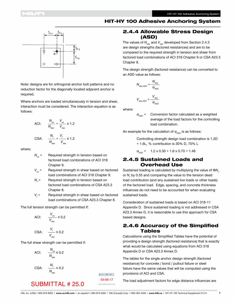
HIT-HY 100 Adhesive Anchoring System
HIT-HY 100 Adhesive Anchoring System
10 Hilti Inc (USA) 1-800-879-8000 I wwwushilticom I en espantildeol 1-800-879-5000 I Hilti (Canada) Corp 1-800-363-4458 I wwwhiltica I HIT-HY 100 Technical Supplement 0114
Table 1 mdash Hilti HIT-HY 100 Adhesive Design Strength (Factored Resistance) with Concrete Bond Failure for US Rebar in Uncracked Concrete 12345678
NominalRebar Size
EffectiveEmbedment
Depthin (mm)
Tension mdash ϕNn or Nr Shear mdash ϕVn or Vr
f´c = 2500 psi (172 Mpa)
lb (kN)
f´c = 3000 psi (207 Mpa)
lb (kN)
f´c = 4000 psi (276 Mpa)
lb (kN)
f´c = 6000 psi (414 Mpa)
lb (kN)
f´c = 2500 psi (172 Mpa)
lb (kN)
f´c = 3000 psi (207 Mpa)
lb (kN)
f´c = 4000 psi (276 Mpa)
lb (kN)
f´c = 6000 psi (414 Mpa)
lb (kN)
3
3-38 3155 3155 3155 3340 6790 6790 6790 7200(86) (140) (140) (140) (149) (302) (302) (302) (320)
4-12 4205 4205 4205 4455 9055 9055 9055 9600(114) (187) (187) (187) (198) (403) (403) (403) (427)7-12 7005 7005 7005 7425 15090 15090 15090 15995(191) (312) (312) (312) (330) (671) (671) (671) (711)
4
4-12 5605 5605 5605 5940 12075 12075 12075 12800(114) (249) (249) (249) (264) (537) (537) (537) (569)
6 7475 7475 7475 7920 16100 16100 16100 17065(152) (333) (333) (333) (352) (716) (716) (716) (759)10 12455 12455 12455 13205 26830 26830 26830 28440
(254) (554) (554) (554) (587) (1193) (1193) (1193) (1265)
5
5-58 8760 8760 8760 9285 18865 18865 18865 19995(143) (390) (390) (390) (413) (839) (839) (839) (889)7-12 11680 11680 11680 12380 25150 25150 25150 26660(191) (520) (520) (520) (551) (1119) (1119) (1119) (1186)
12-12 19465 19465 19465 20630 41920 41920 41920 44435(318) (866) (866) (866) (918) (1865) (1865) (1865) (1977)
6
6-34 12610 12610 12610 13370 27165 27165 27165 28795(171) (561) (561) (561) (595) (1208) (1208) (1208) (1281)
9 16815 16815 16815 17825 36220 36220 36220 38395(229) (748) (748) (748) (793) (1611) (1611) (1611) (1708)15 28025 28025 28025 29710 60365 60365 60365 63990
(381) (1247) (1247) (1247) (1322) (2685) (2685) (2685) (2846)
7
7-78 17165 17165 17165 18195 36975 36975 36975 39190(200) (764) (764) (764) (809) (1645) (1645) (1645) (1743)
10-12 22890 22890 22890 24260 49300 49300 49300 52255(267) (1018) (1018) (1018) (1079) (2193) (2193) (2193) (2324)
17-12 38150 38150 38150 40435 82165 82165 82165 87095(445) (1697) (1697) (1697) (1799) (3655) (3655) (3655) (3874)
8
9 21060 22420 22420 23765 45360 48295 48295 51190(229) (937) (997) (997) (1057) (2018) (2148) (2148) (2277)12 29895 29895 29895 31690 64390 64390 64390 68255
(305) (1330) (1330) (1330) (1410) (2864) (2864) (2864) (3036)20 49825 49825 49825 52815 107315 107315 107315 113755
(508) (2216) (2216) (2216) (2349) (4774) (4774) (4774) (5060)
9
10-18 24010 24010 24010 25450 54125 59290 61120 64785(257) (1068) (1068) (1068) (1132) (2408) (2637) (2719) (2882)
13-12 32015 32015 32015 33935 81495 81495 81495 86385(343) (1424) (1424) (1424) (1509) (3625) (3625) (3625) (3843)
22-12 53360 53360 53360 56560 135825 135825 135825 143970(572) (2374) (2374) (2374) (2516) (6042) (6042) (6042) (6404)
10
11-14 29430 29645 29645 31425 63395 69445 75455 79985(286) (1309) (1319) (1319) (1398) (2820) (3089) (3356) (3558)15 39525 39525 39525 41895 97600 100610 100610 106645
(381) (1758) (1758) (1758) (1864) (4341) (4475) (4475) (4744)25 65875 65875 65875 69830 167685 167685 167685 177745
(635) (2930) (2930) (2930) (3106) (7459) (7459) (7459) (7906)
1 See Section 24 for explanation on development of load values2 See Section 244 to convert design strength (factored resistance) value to ASD value3 Linear interpolation between embedment depths and concrete compressive strengths is not permitted4 Apply spacing edge distance and concrete thickness factors in tables 3 - 10 as necessary Compare to the steel values in table 2
The lesser of the values is to be used for the design5 Data is for temperature range A Max short term temperature = 104deg F (40deg C) max long term temperature = 75deg F (24deg C)
For temperature range B Max short term temperature = 176deg F (80deg C) max long term temperature = 122deg F (50deg C) multiply above value by 083 For temperature range C Max short term temperature = 248deg F (120deg C) max long term temperature = 162deg F (72deg C) multiply above value by 048 Short term elevated concrete temperatures are those that occur over brief intervals eg as a result of diurnal cycling Long term concrete temperatures are roughly constant over significant periods of time
6 Tabular values are for dry and water-saturated concrete conditions7 Tabular values are for short term loads only For sustained loads including overhead use see Section 2458 Tabular values are for normal weight concrete only For lightweight concrete multiply design strength (factored resistance) by λa as follows
For sand-lightweight λa = 051 For all-lightweight λa = 045
SUBMITTAL 25003-06-17
HIT-HY 100 Adhesive Anchoring System
HIT-HY 100 Adhesive Anchoring System
11Hilti Inc (USA) 1-800-879-8000 I wwwushilticom I en espantildeol 1-800-879-5000 I Hilti (Canada) Corp 1-800-363-4458 I wwwhiltica I HIT-HY 100 Technical Supplement 0114
Table 2 mdash Steel Design Strength (ACI 318 Appendix D Based Design) for US Rebar 3
NominalRebar Size
ASTM A 615 Grade 40 4 ASTM A 615 Grade 60 4 ASTM A 706 Grade 60 4 Tensile1
ϕNsa
lb (kN)
Shear2
ϕVsa
lb (kN)
Tensile1
ϕNsa
lb (kN)
Shear2
ϕVsa
lb (kN)
Tensile1
ϕNsa
lb (kN)
Shear2
ϕVsa
lb (kN)
34290 2375 6435 3565 6600 3430(191) (106) (286) (159) (294) (153)
47800 4320 11700 6480 12000 6240(347) (192) (520) (288) (534) (278)
512090 6695 18135 10045 18600 9670(538) (298) (807) (447) (827) (430)
617160 9505 25740 14255 26400 13730(763) (423) (1145) (634) (1174) (611)
723400 12960 35100 19440 36000 18720(1041) (576) (1561) (865) (1601) (833)
830810 17065 46215 25595 47400 24650(1370) (759) (2056) (1139) (2108) (1096)
939000 21600 58500 32400 60000 31200(1735) (961) (2602) (1441) (2669) (1388)
1049530 27430 74295 41150 76200 39625(2203) (1220) (3305) (1830) (3390) (1763)
1 Tensile = ϕ AseN futa as noted in ACI 318 Appendix D2 Shear = ϕ 060 AseN futa as noted in ACI 318 Appendix D3 See Section 244 to convert design strength (factored resistance) value to ASD value4 ASTM A706 Grade 60 rebar are considered ductile steel elements ASTM A 615 Grade 40 and 60 rebar are considered brittle steel elements
Table 3 mdash Load Adjustment Factors for 3 US Rebar in Uncracked Concrete 12
3Uncracked Concrete
Spacing Factor in Tension
fAN
Edge Distance Factor in Tension
fRN
Spacing Factor in Shear3
fAV
Edge Distance in ShearConc Thickness Factor in Shear4
fHV
Toward Edge
fRV
To Edge
fRV
Embedment hef in (mm)
3-38 4-12 7-12 3-38 4-12 7-12 3-38 4-12 7-12 3-38 4-12 7-12 3-38 4-12 7-12 3-38 4-12 7-12(86) (114) (191) (86) (114) (191) (86) (114) (191) (86) (114) (191) (86) (114) (191) (86) (114) (191)
Spac
ing
(s)
Edg
e D
ista
nce
(ca)
Con
cret
e Th
ickn
ess
(h)
mdash in
(mm
)
1-34 (44) na na na 032 023 013 na na na 011 008 005 022 016 010 na na na1-78 (48) 059 057 054 033 024 014 054 053 052 012 009 005 024 018 011 na na na
2 (51) 060 057 054 034 025 014 054 054 053 013 010 006 027 020 012 na na na3 (76) 065 061 057 043 031 018 057 055 054 024 018 011 046 037 022 na na na
3-58 (92) 068 063 058 049 036 021 058 056 055 032 024 015 052 042 029 na na na4 (102) 070 065 059 053 038 022 059 057 055 038 028 017 055 045 034 na na na
4-58 (117) 073 067 060 060 044 025 060 058 056 047 035 021 062 049 036 063 na na5 (127) 075 069 061 065 048 028 061 059 056 052 039 024 065 051 037 066 na na
5-34 (146) 078 071 063 075 055 032 062 060 057 065 048 029 075 057 040 071 064 na6 (152) 080 072 063 078 057 033 063 061 058 069 052 031 078 059 041 072 066 na7 (178) 085 076 066 091 067 039 065 063 059 087 065 039 091 067 045 078 071 na8 (203) 090 080 068 100 076 044 067 064 060 100 080 048 100 076 048 083 076 na
8-34 (222) 093 082 069 083 048 069 066 061 091 055 083 051 087 079 0679 (229) 094 083 070 086 050 070 066 061 095 057 086 052 088 080 068
10 (254) 099 087 072 095 055 072 068 063 100 067 095 057 093 085 07111 (279) 100 091 074 100 061 074 070 064 077 100 061 098 089 07512 (305) 094 077 066 076 071 065 088 066 100 093 07814 (356) 100 081 077 080 075 068 100 077 100 08416 (406) 086 088 085 079 070 088 09018 (457) 090 099 089 082 073 099 09624 (610) 100 100 100 093 081 100 10030 (762) 100 08836 (914) 096
gt48 (1219) 1001 Linear interpolation not permitted2 Shaded area with reduced edge distance is permitted provided rebar has no installation torque3 Spacing factor reduction in shear fAV assumes an influence of a nearby edge If no edge exists then fAV = fAN4 Concrete thickness reduction factor in shear fHV assumes an influence of a nearby edge If no edge exists then fHV = 10
SUBMITTAL 25003-06-17
HIT-HY 100 Adhesive Anchoring System
HIT-HY 100 Adhesive Anchoring System
12 Hilti Inc (USA) 1-800-879-8000 I wwwushilticom I en espantildeol 1-800-879-5000 I Hilti (Canada) Corp 1-800-363-4458 I wwwhiltica I HIT-HY 100 Technical Supplement 0114
Table 4 mdash Load Adjustment Factors for 4 US Rebar in Uncracked Concrete 12
4Uncracked Concrete
Spacing Factor in Tension
fAN
Edge Distance Factor in Tension
fRN
Spacing Factor in Shear3
fAV
Edge Distance in ShearConc Thickness Factor in Shear4
fHV
Toward Edge
fRV
To Edge
fRV
Embedment hef in (mm)
4-12 6 10 4-12 6 10 4-12 6 10 4-12 6 10 4-12 6 10 4-12 6 10(114) (152) (254) (114) (152) (254) (114) (152) (254) (114) (152) (254) (114) (152) (254) (114) (152) (254)
Spac
ing
(s)
Edg
e D
ista
nce
(ca)
Con
cret
e Th
ickn
ess
(h)
mdash in
(mm
) 1-34 (44) na na na 027 020 012 na na na 007 005 003 014 011 006 na na na2-12 (64) 059 057 054 032 023 014 054 053 052 012 009 005 024 018 011 na na na
3 (76) 061 058 055 035 026 015 055 054 053 016 012 007 032 024 014 na na na4 (102) 065 061 057 042 030 018 057 055 054 024 018 011 045 037 022 na na na5 (127) 069 064 058 049 036 021 058 057 055 034 026 015 051 042 031 na na na
5-34 (146) 071 066 060 055 040 023 059 058 055 042 031 019 057 046 034 061 na na6 (152) 072 067 060 057 042 024 060 058 056 045 034 020 059 047 035 062 na na7 (178) 076 069 062 067 049 029 061 059 057 056 042 025 067 052 038 067 na na
7-14 (184) 077 070 062 069 051 030 062 060 057 059 045 027 069 053 038 069 062 na8 (203) 080 072 063 076 056 033 063 061 058 069 052 031 076 057 040 072 066 na9 (229) 083 075 065 086 063 037 065 062 059 082 062 037 086 063 043 076 069 na
10 (254) 087 078 067 095 070 041 066 063 060 096 072 043 095 070 046 081 073 na11-14 (286) 092 081 069 100 078 046 068 065 061 100 086 052 100 078 050 086 078 066
12 (305) 094 083 070 084 049 070 066 061 095 057 084 052 088 080 06814 (356) 100 089 073 098 057 073 069 063 100 072 098 058 095 087 07316 (406) 094 077 100 065 076 071 065 088 100 065 100 093 07818 (457) 100 080 073 079 074 067 100 073 098 08320 (508) 083 082 083 077 069 082 100 08722 (559) 087 090 086 080 071 090 09224 (610) 090 098 089 082 073 098 09630 (762) 100 100 099 090 079 100 10036 (914) 100 098 084
gt48 (1219) 100 096
1 Linear interpolation not permitted2 Shaded area with reduced edge distance is permitted provided rebar has no installation torque3 Spacing factor reduction in shear fAV assumes an influence of a nearby edge If no edge exists then fAV = fAN4 Concrete thickness reduction factor in shear fHV assumes an influence of a nearby edge If no edge exists then fHV = 10
Table 5 mdash Load Adjustment Factors for 5 US Rebar in Uncracked Concrete 12
5Uncracked Concrete
Spacing Factor in Tension
fAN
Edge Distance Factor in Tension
fRN
Spacing Factor in Shear3
fAV
Edge Distance in ShearConc Thickness Factor in Shear4
fHV
Toward Edge
fRV
To Edge
fRV
Embedment hef in (mm)
5-58 7-12 12-12 5-58 7-12 12-12 5-58 7-12 12-12 5-58 7-12 12-12 5-58 7-12 12-12 5-58 7-12 12-12(143) (191) (318) (143) (191) (318) (143) (191) (318) (143) (191) (318) (143) (191) (318) (143) (191) (318)
Spac
ing
(s)
Edg
e D
ista
nce
(ca)
Con
cret
e Th
ickn
ess
(h)
mdash in
(mm
)
1-34 (44) na na na 025 019 011 na na na 005 004 002 010 008 005 na na na3-18 (79) 059 057 054 032 023 014 054 053 052 012 009 005 024 018 011 na na na
4 (102) 062 059 055 036 027 016 055 054 053 017 013 008 035 026 016 na na na4-58 (117) 064 060 056 039 029 017 056 055 054 022 016 010 043 033 020 na na na
5 (127) 065 061 057 041 030 018 057 055 054 024 018 011 045 037 022 na na na6 (152) 068 063 058 047 034 020 058 056 055 032 024 014 050 041 029 na na na7 (178) 071 066 059 053 039 023 059 058 055 040 030 018 055 045 034 na na na
7-18 (181) 071 066 060 054 040 023 059 058 055 041 031 019 056 046 034 061 na na8 (203) 074 068 061 061 045 026 060 059 056 049 037 022 061 049 036 065 na na9 (229) 077 070 062 068 050 029 062 060 057 059 044 026 068 053 038 068 062 na
10 (254) 080 072 063 076 056 033 063 061 058 069 052 031 076 057 040 072 066 na11 (279) 083 074 065 083 061 036 064 062 058 079 060 036 083 062 042 076 069 na12 (305) 086 077 066 091 067 039 066 063 059 091 068 041 091 067 045 079 072 na14 (356) 091 081 069 100 078 046 068 065 061 100 086 051 100 078 049 085 078 06516 (406) 097 086 071 089 052 071 067 062 100 063 089 054 091 083 07018 (457) 100 090 074 100 059 073 069 064 075 100 059 097 088 07420 (508) 094 077 065 076 071 065 088 065 100 093 07822 (559) 099 079 072 079 074 067 100 072 097 08224 (610) 100 082 078 081 076 068 078 100 08626 (660) 085 085 084 078 070 085 08928 (711) 087 091 086 080 071 091 09230 (762) 090 098 089 082 073 098 09636 (914) 098 100 097 089 077 100 100
gt48 (1219) 100 100 100 087
SUBMITTAL 250 03-06-17
HIT-HY 100 Adhesive Anchoring System
HIT-HY 100 Adhesive Anchoring System
13Hilti Inc (USA) 1-800-879-8000 I wwwushilticom I en espantildeol 1-800-879-5000 I Hilti (Canada) Corp 1-800-363-4458 I wwwhiltica I HIT-HY 100 Technical Supplement 0114
Table 6 mdash Load Adjustment Factors for 6 US Rebar in Uncracked Concrete 12
6Uncracked Concrete
Spacing Factor in Tension
fAN
Edge Distance Factor in Tension
fRN
Spacing Factor in Shear3
fAV
Edge Distance in Shear Conc Thickness Factor in Shear4
fHV
Toward Edge
fRV
To Edge
fRV
Embedment hef in (mm)
6-34 9 15 6-34 9 15 6-34 9 15 6-34 9 15 6-34 9 15 6-34 9 15(171) (229) (381) (171) (229) (381) (171) (229) (381) (171) (229) (381) (171) (229) (381) (171) (229) (381)
Spac
ing
(s)
Edg
e D
ista
nce
(ca)
Con
cret
e Th
ickn
ess
(h)
mdash in
(mm
)
1-34 (44) na na na 024 018 010 na na na 004 003 002 008 006 003 na na na3-34 (95) 059 057 054 032 023 014 054 053 052 012 009 005 024 018 011 na na na
4 (102) 060 057 054 033 024 014 054 054 053 013 010 006 026 019 012 na na na5 (127) 062 059 056 037 027 016 055 054 053 018 014 008 036 027 016 na na na
5-14 (133) 063 060 056 038 028 016 056 055 053 020 015 009 039 029 018 na na na6 (152) 065 061 057 041 030 018 056 055 054 024 018 011 045 036 021 na na na7 (178) 067 063 058 046 034 020 057 056 054 030 023 014 049 041 027 na na na8 (203) 070 065 059 051 037 022 059 057 055 037 028 017 053 044 033 na na na
8-12 (216) 071 066 059 054 039 023 059 057 055 040 030 018 056 045 034 060 na na9 (229) 072 067 060 057 042 024 060 058 056 044 033 020 058 047 035 062 na na
10 (254) 075 069 061 063 046 027 061 059 056 051 039 023 063 050 037 065 na na10-34 (273) 077 070 062 068 050 029 061 059 057 057 043 026 068 053 038 068 062 na
12 (305) 080 072 063 076 056 033 063 061 058 067 051 030 076 057 040 072 065 na14 (356) 085 076 066 088 065 038 065 062 059 085 064 038 088 065 044 077 070 na16 (406) 090 080 068 100 074 043 067 064 060 100 078 047 100 074 048 083 075 na
16-34 (425) 091 081 069 078 045 068 065 061 083 050 078 049 085 077 06518 (457) 094 083 070 083 049 069 066 061 093 056 083 052 088 080 06720 (508) 099 087 072 093 054 071 068 063 100 065 093 056 092 084 07122 (559) 100 091 074 100 060 074 069 064 075 100 060 097 088 07424 (610) 094 077 065 076 071 065 086 065 100 092 07826 (660) 098 079 071 078 073 066 097 071 096 08128 (711) 100 081 076 080 075 068 100 076 099 08430 (762) 083 081 082 076 069 081 100 08736 (914) 090 098 088 082 073 098 095
gt48 (1219) 100 100 100 092 080 100 100
1 Linear interpolation not permitted2 Shaded area with reduced edge distance is permitted provided rebar has no installation torque3 Spacing factor reduction in shear fAV assumes an influence of a nearby edge If no edge exists then fAV = fAN4 Concrete thickness reduction factor in shear fHV assumes an influence of a nearby edge If no edge exists then fHV = 10
Table 7 mdash Load Adjustment Factors for 7 US Rebar in Uncracked Concrete 12
7Uncracked Concrete
Spacing Factor in Tension
fAN
Edge Distance Factor in Tension
fRN
Spacing Factor in Shear3
fAV
Edge Distance in Shear Conc Thickness Factor in Shear4
fHV
Toward Edge
fRV
To Edge
fRV
Embedment hef in (mm)
7-78 10-12 17-12 7-78 10-12 17-12 7-78 10-12 17-12 7-78 10-12 17-12 7-78 10-12 17-12 7-78 10-12 17-12(200) (267) (445) (200) (267) (445) (200) (267) (445) (200) (267) (445) (200) (267) (445) (200) (267) (445)
Spac
ing
(s)
Edg
e D
ista
nce
(ca)
Con
cret
e Th
ickn
ess
(h)
mdash in
(mm
)
1-34 (44) na na na 023 017 010 na na na 003 002 001 006 004 002 na na na4-38 (111) 059 057 054 032 023 014 054 053 052 011 008 005 022 016 010 na na na
5 (127) 061 058 055 034 025 015 054 054 053 013 010 006 027 020 012 na na na5-12 (140) 062 059 055 036 026 015 055 054 053 015 012 007 031 023 014 na na na
6 (152) 063 060 056 037 028 016 055 054 053 018 013 008 035 026 016 na na na7 (178) 065 061 057 041 030 018 056 055 054 022 017 010 044 033 020 na na na8 (203) 067 063 058 045 033 019 057 056 054 027 020 012 048 040 024 na na na9 (229) 069 064 059 049 036 021 058 056 055 032 024 014 052 043 029 na na na
9-78 (251) 071 066 059 053 039 023 059 057 055 037 028 017 056 045 033 059 na na10 (254) 071 066 060 054 040 023 059 057 055 038 028 017 056 045 034 059 na na11 (279) 073 067 060 059 044 026 060 058 056 044 033 020 060 048 036 062 na na12 (305) 075 069 061 065 048 028 060 059 056 050 037 022 065 051 037 065 na na
12-12 (318) 076 070 062 067 050 029 061 059 056 053 040 024 067 053 038 066 060 na14 (356) 080 072 063 075 055 033 062 060 057 062 047 028 075 057 040 070 063 na16 (406) 084 075 065 086 063 037 064 061 058 076 057 034 086 063 043 075 068 na18 (457) 088 079 067 097 071 042 066 063 059 091 068 041 097 071 047 079 072 na
19-12 (495) 091 081 069 100 077 045 067 064 060 100 077 046 100 077 049 082 075 06320 (508) 092 082 069 079 046 067 064 060 080 048 079 050 083 076 06422 (559) 097 085 071 087 051 069 066 061 092 055 087 053 088 079 06724 (610) 100 088 073 095 056 071 067 062 100 063 095 057 091 083 07026 (660) 091 075 100 060 073 069 063 071 100 061 095 086 07328 (711) 094 077 065 074 070 064 080 065 099 090 07630 (762) 098 079 070 076 072 065 088 070 100 093 07836 (914) 100 084 084 081 076 068 100 084 100 086
gt48 (1219) 096 100 092 084 075 100 099
SUBMITTAL 250 03-06-17
HIT-HY 100 Adhesive Anchoring System
HIT-HY 100 Adhesive Anchoring System
14 Hilti Inc (USA) 1-800-879-8000 I wwwushilticom I en espantildeol 1-800-879-5000 I Hilti (Canada) Corp 1-800-363-4458 I wwwhiltica I HIT-HY 100 Technical Supplement 0114
Table 8 mdash Load Adjustment Factors for 8 US Rebar in Uncracked Concrete 12
8Uncracked Concrete
Spacing Factor in Tension
fAN
Edge Distance Factor in Tension
fRN
Spacing Factor in Shear3
fAV
Edge Distance in Shear Conc Thickness Factor in Shear4
fHV
Toward Edge
fRV
To Edge
fRV
Embedment hef in (mm)
9 12 20 9 12 20 9 12 20 9 12 20 9 12 20 9 12 20(229) (305) (508) (229) (305) (508) (229) (305) (508) (229) (305) (508) (229) (305) (508) (229) (305) (508)
Spac
ing
(s)
Edg
e D
ista
nce
(ca)
Con
cret
e Th
ickn
ess
(h)
mdash in
(mm
)
1-34 (44) na na na 023 017 010 na na na 002 002 001 005 003 002 na na na5 (127) 059 057 054 032 023 014 054 053 052 011 008 005 022 015 009 na na na6 (152) 061 058 055 035 025 015 055 054 053 014 010 006 029 020 012 na na na
6-14 (159) 062 059 055 035 026 015 055 054 053 015 011 006 030 021 013 na na na7 (178) 063 060 056 038 028 016 055 054 053 018 013 008 036 025 015 na na na8 (203) 065 061 057 041 030 018 056 055 053 022 015 009 044 031 019 na na na9 (229) 067 063 058 045 033 019 057 055 054 026 018 011 048 037 022 na na na
10 (254) 069 064 058 048 035 021 058 056 054 031 022 013 051 042 026 na na na11 (279) 070 065 059 052 038 022 058 057 055 035 025 015 055 044 030 na na na
11-14 (286) 071 066 059 053 039 023 059 057 055 037 026 016 055 045 031 058 na na12 (305) 072 067 060 057 042 024 059 057 055 040 028 017 058 047 034 060 na na13 (330) 074 068 061 061 045 026 060 058 056 046 032 019 062 049 036 063 na na14 (356) 076 069 062 066 049 028 061 058 056 051 036 022 066 052 038 065 na na
14-14 (362) 076 070 062 067 049 029 061 059 056 052 037 022 067 052 038 066 059 na16 (406) 080 072 063 075 055 033 062 060 057 062 044 026 075 057 040 070 062 na18 (457) 083 075 065 085 062 037 064 061 058 074 052 031 085 062 043 074 066 na20 (508) 087 078 067 094 069 041 065 062 059 087 061 037 094 069 046 078 069 na22 (559) 091 081 068 100 076 045 067 063 059 100 071 042 100 076 049 082 073 na
22-14 (565) 091 081 069 077 045 067 063 060 072 043 077 049 082 073 06224 (610) 094 083 070 083 049 068 064 060 081 048 083 052 085 076 06426 (660) 098 086 072 090 053 070 066 061 091 054 090 055 089 079 06728 (711) 100 089 073 097 057 071 067 062 100 061 097 058 092 082 06930 (762) 092 075 100 061 073 068 063 068 100 061 095 085 07236 (914) 100 080 073 077 072 065 089 073 100 093 078
gt48 (1219) 090 098 086 079 071 100 098 100 091
1 Linear interpolation not permitted2 Shaded area with reduced edge distance is permitted provided rebar has no installation torque3 Spacing factor reduction in shear fAV assumes an influence of a nearby edge If no edge exists then fAV = fAN4 Concrete thickness reduction factor in shear fHV assumes an influence of a nearby edge If no edge exists then fHV = 10
Table 9 mdash Load Adjustment Factors for 9 US Rebar in Uncracked Concrete 12
9Uncracked Concrete
Spacing Factor in Tension
fAN
Edge Distance Factor in Tension
fRN
Spacing Factor in Shear3
fAV
Edge Distance in Shear Conc Thickness Factor in Shear4
fHV
Toward Edge
fRV
To Edge
fRV
Embedment hef in (mm)
10-18 13-12 22-12 10-18 13-12 22-12 10-18 13-12 22-12 10-18 13-12 22-12 10-18 13-12 22-12 10-18 13-12 22-12(257) (343) (572) (257) (343) (572) (257) (343) (572) (257) (343) (572) (257) (343) (572) (257) (343) (572)
Spac
ing
(s)
Edg
e D
ista
nce
(ca)
Con
cret
e Th
ickn
ess
(h)
mdash in
(mm
)
1-34 (44) na na na 022 016 010 na na na 002 001 001 004 003 002 na na na5-58 (143) 059 057 054 032 023 014 054 053 052 011 007 004 022 014 009 na na na
6 (152) 060 057 054 033 024 014 054 053 052 012 008 005 024 016 010 na na na7 (178) 062 059 055 036 026 015 055 054 053 015 010 006 030 020 012 na na na
7-14 (184) 062 059 055 036 027 016 055 054 053 016 011 006 032 021 013 na na na8 (203) 063 060 056 038 028 017 055 054 053 018 012 007 037 024 015 na na na9 (229) 065 061 057 041 030 018 056 055 053 022 015 009 044 029 018 na na na
10 (254) 066 062 057 045 033 019 057 055 054 026 017 010 048 034 021 na na na11 (279) 068 064 058 048 035 020 057 056 054 030 020 012 051 039 024 na na na12 (305) 070 065 059 051 037 022 058 056 054 034 022 013 054 044 027 na na na
12-78 (327) 071 066 060 054 040 023 059 057 055 038 025 015 056 046 030 059 na na13 (330) 071 066 060 055 040 024 059 057 055 038 025 015 057 046 030 059 na na14 (356) 073 067 060 059 043 025 059 057 055 043 028 017 060 048 034 061 na na16 (406) 076 070 062 067 050 029 061 058 056 052 035 021 067 053 038 066 na na
16-14 (413) 077 070 062 069 050 029 061 058 056 053 035 021 069 053 038 066 058 na18 (457) 080 072 063 076 056 033 062 059 057 062 041 025 076 057 040 070 061 na20 (508) 083 075 065 084 062 036 063 060 057 073 048 029 084 062 043 073 064 na22 (559) 086 077 066 093 068 040 065 061 058 084 056 034 093 068 045 077 067 na24 (610) 090 080 068 100 074 043 066 062 059 096 064 038 100 074 048 080 070 na
25-14 (641) 092 081 069 078 046 067 063 059 100 069 041 078 049 083 072 06126 (660) 093 082 069 080 047 068 063 060 072 043 080 050 084 073 06228 (711) 096 085 071 087 051 069 064 060 080 048 087 053 087 076 06430 (762) 099 087 072 093 054 070 065 061 089 053 093 056 090 079 06636 (914) 100 094 077 100 065 074 068 063 100 070 100 065 099 086 073
gt48 (1219) 100 086 087 082 075 068 100 087 100 099 084
SUBMITTAL 250 03-06-17
HIT-HY 100 Adhesive Anchoring System
HIT-HY 100 Adhesive Anchoring System
15Hilti Inc (USA) 1-800-879-8000 I wwwushilticom I en espantildeol 1-800-879-5000 I Hilti (Canada) Corp 1-800-363-4458 I wwwhiltica I HIT-HY 100 Technical Supplement 0114
Table 10 mdash Load Adjustment Factors for 10 US Rebar in Uncracked Concrete 12
10Uncracked Concrete
Spacing Factor in Tension
fAN
Edge Distance Factor in Tension
fRN
Spacing Factor in Shear3
fAV
Edge Distance in ShearConc Thickness Factor in Shear4
fHV
Toward Edge
fRV
To Edge
fRV
Embedment hef in (mm)
11-14 15 25 11-14 15 25 11-14 15 25 11-14 15 25 11-14 15 25 11-14 15 25(286) (381) (635) (286) (381) (635) (286) (381) (635) (286) (381) (635) (286) (381) (635) (286) (381) (635)
Spac
ing
(s)
Edg
e D
ista
nce
(ca)
Con
cret
e Th
ickn
ess
(h)
mdash in
(mm
) 1-34 (44) na na na 022 016 009 na na na 002 001 001 003 002 001 na na na6-14 (159) 059 057 054 032 023 014 054 053 052 011 007 004 022 014 008 na na na
7 (178) 060 058 055 034 025 014 054 053 052 013 008 005 026 017 010 na na na8 (203) 062 059 055 036 027 016 055 054 053 016 010 006 031 020 012 na na na9 (229) 063 060 056 039 028 017 055 054 053 019 012 007 038 024 014 na na na
10 (254) 065 061 057 041 030 018 056 055 053 022 014 008 044 029 017 na na na11 (279) 066 062 057 044 032 019 057 055 053 025 016 010 047 033 019 na na na12 (305) 068 063 058 047 034 020 057 055 054 029 019 011 050 038 022 na na na13 (330) 069 064 059 050 037 021 058 056 054 033 021 012 053 042 025 na na na14 (356) 071 066 059 053 039 023 059 056 054 036 024 014 055 045 028 na na na
14-14 (362) 071 066 060 054 040 023 059 056 055 037 024 014 056 046 028 059 na na15 (381) 072 067 060 057 042 024 059 057 055 040 026 015 058 047 031 060 na na16 (406) 074 068 061 061 045 026 060 057 055 045 029 017 061 049 034 062 na na17 (432) 075 069 061 064 047 028 060 058 055 049 032 018 064 051 037 064 na na18 (457) 077 070 062 068 050 029 061 058 056 053 035 020 068 053 038 066 057 na20 (508) 080 072 063 076 056 033 062 059 056 062 040 024 076 057 040 070 060 na22 (559) 083 074 065 083 061 036 063 060 057 072 047 027 083 062 042 073 063 na24 (610) 086 077 066 091 067 039 065 061 058 082 053 031 091 067 045 076 066 na26 (660) 089 079 067 099 072 042 066 062 058 092 060 035 099 072 047 079 069 na28 (711) 091 081 069 100 078 046 067 063 059 100 067 039 100 078 049 082 071 06030 (762) 094 083 070 083 049 068 064 060 074 043 083 052 085 074 06236 (914) 100 090 074 100 059 072 066 061 098 057 100 059 094 081 068
gt48 (1219) 100 082 078 079 072 065 100 087 078 100 094 078
1 Linear interpolation not permitted2 Shaded area with reduced edge distance is permitted provided rebar has no installation torque3 Spacing factor reduction in shear fAV assumes an influence of a nearby edge If no edge exists then fAV = fAN4 Concrete thickness reduction factor in shear fHV assumes an influence of a nearby edge If no edge exists then fHV = 10
SUBMITTAL 25003-06-17
HIT-HY 100 Adhesive Anchoring System
HIT-HY 100 Adhesive Anchoring System
16 Hilti Inc (USA) 1-800-879-8000 I wwwushilticom I en espantildeol 1-800-879-5000 I Hilti (Canada) Corp 1-800-363-4458 I wwwhiltica I HIT-HY 100 Technical Supplement 0114
Table 11 mdash Hilti HIT-HY 100 Adhesive Factored Resistance with Concrete Bond Failure for Canadian Rebar in Uncracked Concrete 12345678
NominalRebar Size
EffectiveEmbedment
Depthmm
Tension mdash Nr Shear mdash Vr
f´c = 20 MPa
(kN)
f´c = 25 MPa
(kN)
f´c = 30 MPa
(kN)
f´c = 35 MPa
(kN)
f´c = 40 MPa
(kN)
f´c = 20 MPa
(kN)
f´c = 25 MPa
(kN)
f´c = 30 MPa
(kN)
f´c = 35 MPa
(kN)
f´c = 40 MPa
(kN)
10 M115 223 223 223 236 236 480 480 480 509 509180 349 349 349 370 370 751 751 751 797 797226 438 438 438 464 464 944 944 944 1000 1000
15 M145 398 398 398 422 422 857 857 857 909 909250 686 686 686 727 727 1478 1478 1478 1566 1566320 878 878 878 931 931 1892 1892 1892 2005 2005
20 M200 669 669 669 709 709 1441 1441 1441 1527 1527355 1187 1187 1187 1259 1259 2558 2558 2558 2711 2711390 1304 1304 1304 1383 1383 2810 2810 2810 2978 2978
25 M230 994 994 994 1054 1054 2141 2141 2141 2270 2270405 1751 1751 1751 1856 1856 3771 3771 3771 3997 3997504 2179 2179 2179 2309 2309 4692 4692 4692 4974 4974
30 M260 1128 1128 1128 1196 1196 2625 2872 2872 3044 3044455 1975 1975 1975 2093 2093 5026 5026 5026 5328 5328598 2595 2595 2595 2751 2751 6606 6606 6606 7002 7002
1 See Section 24 for explanation on development of load values2 See Section 244 to convert design strength (factored resistance) value to ASD value3 Linear interpolation between embedment depths and concrete compressive strengths is not permitted4 Apply spacing edge distance and concrete thickness factors in tables 13 - 17 as necessary Compare to the steel values in table 12
The lesser of the values is to be used for the design5 Data is for temperature range A Max short term temperature = 104deg F (40deg C) max long term temperature = 75deg F (24deg C)
For temperature range B Max short term temperature = 176deg F (80deg C) max long term temperature = 122deg F (50deg C) multiply above value by 083 For temperature range C Max short term temperature = 248deg F (120deg C) max long term temperature = 162deg F (72deg C) multiply above value by 048 Short term elevated concrete temperatures are those that occur over brief intervals eg as a result of diurnal cycling Long term concrete temperatures are roughly constant over significant periods of time
6 Tabular values are for dry and water-saturated concrete conditions7 Tabular values are for short term loads only For sustained loads including overhead use see Section 2458 Tabular values are for normal weight concrete only For lightweight concrete multiply design strength (factored resistance) by λa as follows
For sand-lightweight λa = 051 For all-lightweight λa = 045
Table 12 mdash Steel Factored Resistance (CSA A233 Annex D Based Design) for Canadian Rebar 3
NominalRebar Size
CSA-G3018 Grade 400 4 Tensile1
Nsr
Shear2
Vsr
10 M 321 17915 M 646 35920 M 961 53625 M 1607 89230 M 2261 1257
1 Tensile = Ase ϕs fut R as noted in CSA A233 Annex D2 Shear = Ase ϕs 060 fut R as noted in CSA A233 Annex D3 See Section 244 to convert factored resistance value to ASD value4 CSA-G3018 Grade 400 rebar are considered brittle steel elements
SUBMITTAL 250 03-06-17
HIT-HY 100 Adhesive Anchoring System
HIT-HY 100 Adhesive Anchoring System
17Hilti Inc (USA) 1-800-879-8000 I wwwushilticom I en espantildeol 1-800-879-5000 I Hilti (Canada) Corp 1-800-363-4458 I wwwhiltica I HIT-HY 100 Technical Supplement 0114
Table 13 mdash Load Adjustment Factors for 10 M Canadian Rebar in Uncracked Concrete 12
10 MUncracked Concrete
Spacing Factor in Tension
fAN
Edge Distance Factor in Tension
fRN
Spacing Factor in Shear3
fAV
Edge Distance in ShearConc Thickness Factor in Shear4
fHV
Toward Edge
fRV
To Edge
fRV
Embedment hef mm
115 180 226 115 180 226 115 180 226 115 180 226 115 180 226 115 180 226
Spac
ing
(s)
Edg
e D
ista
nce
(ca)
Con
cret
e Th
ickn
ess
(h)
mdash in
(mm
)
45 na na na 025 016 012 na na na 008 005 004 016 010 008 na na na50 057 055 054 027 017 013 053 053 052 010 006 005 019 012 010 na na na75 061 057 056 033 020 016 055 054 053 018 011 009 035 022 018 na na na
100 064 059 057 039 024 019 057 055 054 027 017 014 045 035 028 na na na125 068 062 059 047 029 023 059 056 056 038 024 019 051 039 035 na na na150 072 064 061 056 035 028 060 058 057 050 032 025 058 042 037 065 na na175 075 066 063 066 041 032 062 059 058 063 040 032 066 046 040 070 na na200 079 069 065 075 047 037 064 060 059 076 049 039 075 051 043 075 na na225 083 071 067 085 052 041 066 062 060 091 058 046 085 055 047 079 068 na250 086 073 068 094 058 046 067 063 061 100 068 054 094 059 050 083 072 na275 090 075 070 100 064 051 069 064 062 079 063 100 064 053 088 075 070300 093 078 072 070 055 071 066 063 090 071 070 057 091 079 073325 097 080 074 076 060 073 067 064 100 081 076 060 095 082 076350 100 082 076 082 064 074 068 066 090 082 064 099 085 079375 085 078 087 069 076 069 067 100 087 069 100 088 082400 087 079 093 074 078 071 068 093 074 091 084450 092 083 100 083 081 073 070 100 083 096 089500 096 087 092 085 076 072 092 100 094550 100 091 100 088 078 074 100 099600 094 092 081 077 100700 100 099 086 081800 100 091 0861000 100 094
gt1200 100
1 Linear interpolation not permitted2 Shaded area with reduced edge distance is permitted provided rebar has no installation torque3 Spacing factor reduction in shear fAV assumes an influence of a nearby edge If no edge exists then fAV = fAN4 Concrete thickness reduction factor in shear fHV assumes an influence of a nearby edge If no edge exists then fHV = 10
Table 14 mdash Load Adjustment Factors for 15 M Canadian Rebar in Uncracked Concrete 12
15 MUncracked Concrete
Spacing Factor in Tension
fAN
Edge Distance Factor in Tension
fRN
Spacing Factor in Shear3
fAV
Edge Distance in ShearConc Thickness Factor in Shear4
fHV
Toward Edge
fRV
To Edge
fRV
Embedment hef mm
145 250 320 145 250 320 145 250 320 145 250 320 145 250 320 145 250 320
Spac
ing
(s)
Edg
e D
ista
nce
(ca)
Con
cret
e Th
ickn
ess
(h)
mdash in
(mm
)
45 na na na 025 014 011 na na na 005 003 002 011 006 005 na na na75 059 055 054 030 017 013 054 053 052 012 007 005 023 014 011 na na na
100 061 057 055 035 020 015 055 054 053 018 010 008 036 021 016 na na na125 064 058 057 040 023 018 057 055 054 025 015 011 044 029 023 na na na150 067 060 058 045 026 020 058 056 055 033 019 015 049 036 030 na na na175 070 062 059 051 029 022 059 056 055 042 024 019 054 038 034 061 na na200 073 063 060 058 033 026 061 057 056 051 030 023 060 041 036 065 na na225 076 065 062 066 037 029 062 058 057 061 035 028 066 044 038 069 na na250 079 067 063 073 041 032 063 059 058 071 041 032 073 046 040 073 na na275 082 068 064 080 045 035 065 060 059 082 048 037 080 049 042 076 na na300 084 070 066 088 050 038 066 061 059 094 054 042 088 052 044 080 067 na325 087 072 067 095 054 042 067 062 060 100 061 048 095 056 047 083 069 na350 090 073 068 100 058 045 069 063 061 068 053 100 059 049 086 072 066375 093 075 070 062 048 070 064 062 076 059 062 051 089 074 069400 096 077 071 066 051 071 065 063 084 065 066 054 092 077 071450 100 080 073 074 058 074 067 064 100 078 074 058 098 082 075500 083 076 083 064 077 068 066 091 083 064 100 086 079550 087 079 091 070 079 070 067 100 091 070 090 083600 090 081 099 077 082 072 069 099 077 094 087650 093 084 100 083 085 074 070 100 083 098 090700 097 086 090 087 076 072 090 100 094800 100 092 100 093 080 075 100 100
1000 100 100 087 081gt1200 094 088
SUBMITTAL 250
03-06-17
HIT-HY 100 Adhesive Anchoring System
HIT-HY 100 Adhesive Anchoring System
18 Hilti Inc (USA) 1-800-879-8000 I wwwushilticom I en espantildeol 1-800-879-5000 I Hilti (Canada) Corp 1-800-363-4458 I wwwhiltica I HIT-HY 100 Technical Supplement 0114
Table 15 mdash Load Adjustment Factors for 20 M Canadian Rebar in Uncracked Concrete 12
20 MUncracked Concrete
Spacing Factor in Tension
fAN
Edge Distance Factor in Tension
fRN
Spacing Factor in Shear3
fAV
Edge Distance in ShearConc Thickness Factor in Shear4
fHV
Toward Edge
fRV
To Edge
fRV
Embedment hef mm
200 355 390 200 355 390 200 355 390 200 355 390 200 355 390 200 355 390
Spac
ing
(s)
Edg
e D
ista
nce
(ca)
Con
cret
e Th
ickn
ess
(h)
mdash in
(mm
)
45 na na na 021 011 010 na na na 003 002 002 007 004 004 na na na100 058 055 054 028 015 014 054 053 053 011 006 006 023 013 012 na na na125 060 056 055 032 017 016 055 053 053 016 009 008 032 018 016 na na na150 063 057 056 036 019 018 056 054 054 021 012 011 041 024 022 na na na175 065 058 057 039 021 019 057 055 054 027 015 014 045 030 027 na na na200 067 059 059 044 024 022 058 055 055 032 018 017 049 035 033 na na na225 069 061 060 049 026 024 059 056 056 039 022 020 052 037 035 na na na250 071 062 061 054 029 027 060 057 056 045 026 023 056 039 037 na na na275 073 063 062 059 032 029 061 057 057 052 029 027 060 041 038 066 na na300 075 064 063 065 035 032 062 058 058 060 034 031 065 042 040 069 na na325 077 065 064 070 038 035 063 059 058 067 038 034 070 044 042 071 na na350 079 066 065 075 041 037 064 059 059 075 042 038 075 046 044 074 na na375 081 068 066 081 044 040 065 060 059 083 047 043 081 049 046 077 na na400 083 069 067 086 047 043 066 061 060 092 052 047 086 051 047 079 na na450 088 071 069 097 053 048 068 062 061 100 062 056 097 055 051 084 069 067500 092 073 071 100 059 053 070 063 063 072 066 100 059 055 089 073 071550 096 076 074 065 059 072 065 064 083 076 065 059 093 077 074600 100 078 076 070 064 074 066 065 095 086 070 064 097 080 078650 081 078 076 069 076 067 066 100 097 076 069 100 084 081700 083 080 082 074 078 069 068 100 082 074 087 084800 088 084 094 085 081 071 070 094 085 093 090
1000 097 093 100 100 089 077 075 100 100 100 1001200 100 100 097 082 080
gt1500 100 090 088
1 Linear interpolation not permitted2 Shaded area with reduced edge distance is permitted provided rebar has no installation torque3 Spacing factor reduction in shear fAV assumes an influence of a nearby edge If no edge exists then fAV = fAN4 Concrete thickness reduction factor in shear fHV assumes an influence of a nearby edge If no edge exists then fHV = 10
Table 16 mdash Load Adjustment Factors for 25 M Canadian Rebar in Uncracked Concrete 12
25 MUncracked Concrete
Spacing Factor in Tension
fAN
Edge Distance Factor in Tension
fRN
Spacing Factor in Shear3
fAV
Edge Distance in ShearConc Thickness Factor in Shear4
fHV
Toward Edge
fRV
To Edge
fRV
Embedment hef mm
230 405 504 230 405 504 230 405 504 230 405 504 230 405 504 230 405 504
Spac
ing
(s)
Edg
e D
ista
nce
(ca)
Con
cret
e Th
ickn
ess
(h)
mdash in
(mm
)
45 na na na 022 012 010 na na na 002 001 001 005 003 002 na na na125 059 055 054 031 017 014 054 053 052 011 006 005 022 012 010 na na na150 061 056 055 035 019 015 055 053 053 014 008 006 028 016 013 na na na175 063 057 056 038 021 016 055 054 053 018 010 008 036 020 016 na na na200 064 058 057 041 022 018 056 054 054 022 012 010 044 025 020 na na na225 066 059 057 045 024 019 057 055 054 026 015 012 048 030 024 na na na250 068 060 058 048 026 021 058 055 054 030 017 014 052 035 028 na na na275 070 061 059 052 028 023 058 056 055 035 020 016 055 038 032 na na na300 072 062 060 057 031 025 059 056 055 040 023 018 058 040 036 060 na na325 074 063 061 061 034 027 060 057 056 045 026 021 062 041 037 063 na na350 075 064 062 066 036 029 061 057 056 050 029 023 066 043 038 065 na na375 077 065 062 071 039 031 061 058 057 056 032 026 071 045 039 067 na na400 079 066 063 076 041 033 062 058 057 062 035 028 076 047 041 070 na na450 083 069 065 085 046 037 064 059 058 074 042 034 085 050 044 074 na na500 086 071 067 094 052 041 065 060 059 086 049 039 094 054 046 078 064 na550 090 073 068 100 057 045 067 061 060 099 056 045 100 058 049 081 067 na600 093 075 070 062 049 068 062 061 100 064 052 062 052 085 070 066650 097 077 071 067 053 070 063 062 073 058 067 055 089 073 068700 100 079 073 072 058 071 064 063 081 065 072 059 092 076 071750 081 075 077 062 073 066 063 090 072 077 062 095 079 073800 083 076 083 066 074 067 064 099 080 083 066 098 081 076
1000 091 083 100 082 080 071 068 100 100 100 082 100 091 0851200 099 090 099 086 075 071 099 100 093
gt1500 100 100 100 095 081 077 100 100
SUBMITTAL 250
03-06-17
HIT-HY 100 Adhesive Anchoring System
HIT-HY 100 Adhesive Anchoring System
19Hilti Inc (USA) 1-800-879-8000 I wwwushilticom I en espantildeol 1-800-879-5000 I Hilti (Canada) Corp 1-800-363-4458 I wwwhiltica I HIT-HY 100 Technical Supplement 0114
Table 17 mdash Load Adjustment Factors for 30 M Canadian Rebar in Uncracked Concrete 12
30 MUncracked Concrete
Spacing Factor in Tension
fAN
Edge Distance Factor in Tension
fRN
Spacing Factor in Shear3
fAV
Edge Distance in ShearConc Thickness Factor in Shear4
fHV
Toward Edge
fRV
To Edge
fRV
Embedment hef mm
260 455 598 260 455 598 260 455 598 260 455 598 260 455 598 260 455 598
Spac
ing
(s)
Edg
e D
ista
nce
(ca)
Con
cret
e Th
ickn
ess
(h)
mdash in
(mm
)
45 na na na 023 013 009 na na na 002 001 001 004 002 002 na na na150 060 055 054 033 018 014 054 053 052 012 006 005 023 012 009 na na na175 061 056 055 036 020 015 055 053 052 014 008 006 029 015 012 na na na200 063 057 056 039 021 016 055 053 053 018 009 007 035 019 014 na na na225 064 058 056 042 023 017 056 054 053 021 011 008 042 022 017 na na na250 066 059 057 045 025 019 057 054 054 025 013 010 048 026 020 na na na275 068 060 058 048 026 020 057 055 054 029 015 011 051 030 023 na na na300 069 061 058 051 028 021 058 055 054 033 017 013 054 034 026 na na na325 071 062 059 055 030 023 059 056 055 037 019 015 057 038 029 na na na350 072 063 060 059 032 024 059 056 055 041 022 016 060 041 033 061 na na375 074 064 060 063 035 026 060 056 055 045 024 018 063 042 036 063 na na400 076 065 061 067 037 028 061 057 056 050 026 020 067 044 037 065 na na450 079 066 063 076 042 031 062 058 056 060 031 024 076 047 040 069 na na500 082 068 064 084 046 035 063 059 057 070 037 028 084 050 042 072 na na550 085 070 065 092 051 038 064 059 058 081 042 032 092 054 044 076 061 na600 088 072 067 100 055 042 066 060 059 092 048 037 100 057 047 079 064 na650 092 074 068 060 045 067 061 059 100 054 041 061 049 083 067 na700 095 076 070 065 049 068 062 060 061 046 065 052 086 069 063750 098 077 071 069 052 070 063 061 067 051 069 054 089 072 065800 100 079 072 074 055 071 064 061 074 057 074 057 092 074 068900 083 075 083 062 074 065 063 089 067 083 062 097 078 072
1000 087 078 092 069 076 067 064 100 079 092 069 100 083 0751200 094 083 100 083 082 071 067 100 100 083 091 083
gt1500 100 092 100 089 076 071 100 100 092
1 Linear interpolation not permitted2 Shaded area with reduced edge distance is permitted provided rebar has no installation torque3 Spacing factor reduction in shear fAV assumes an influence of a nearby edge If no edge exists then fAV = fAN4 Concrete thickness reduction factor in shear fHV assumes an influence of a nearby edge If no edge exists then fHV = 10
SUBMITTAL 25003-06-17
HIT-HY 100 Adhesive Anchoring System
HIT-HY 100 Adhesive Anchoring System
20 Hilti Inc (USA) 1-800-879-8000 I wwwushilticom I en espantildeol 1-800-879-5000 I Hilti (Canada) Corp 1-800-363-4458 I wwwhiltica I HIT-HY 100 Technical Supplement 0114
249 Hilti HIT-HY 100 Adhesive with Hilti HAS Threaded Rod
Hilti HAS Threaded Rod Installation Conditions
Perm
issi
ble
Con
cret
e C
ondi
tions
UncrackedConcrete
DryConcrete
Perm
issi
ble
Dril
ling
Met
hod
Hammer Drilling with Carbide Tipped Drill Bit Water Saturated
Concrete
Mechanical PropertiesHilti HAS Threaded Rod Material Specifications fya Min futa
ksi (MPa) ksi (MPa)Standard HAS-E rod material meets the requirements of ISO 898 Class 58 58 (400) 725 (500)High Strength or lsquoSuper HASrsquo rod material meets the requirements of ASTM A 193 Grade B7 105 (724) 125 (862)Stainless HAS rod material meets the requirements of ASTM F 593 (AISI 304316) Condition CW1 38 to 58
65 (448) 100 (689)
Stainless HAS rod material meets the requirements of ASTM F 593 (AISI 304316) Condition CW 34 to 1-14
45 (310) 85 (586)
HAS Super amp HAS-E Standard Nut Material meets the requirements of SAE J995 Grade 5HAS Stainless Steel Nut material meets the requirements of ASTM F 594HAS Standard and Stainless Steel Washers meet dimensional requirements of ANSI B18221 Type A PlainHAS Stainless Steel Washers meet the requirements of AISI 304 or AISI 316 conforming to ASTM A 240HAS Super amp HAS-E Standard Washers meet the requirements of ASTM F 884 HVAll HAS Super Rods (except 78rdquo) amp HAS-E Standard nuts amp washers are zinc plated to ASTM B 633 SC 178rdquo HAS Super rods hot-dip galvanized in accordance with ASTM A 153HAS Carbon steel HAS rods are furnished with a 0005-mm-thick zinc electroplated coatingNote Special Order threaded rods may vary from standard materials
Hilti HAS Threaded Rod Installation SpecificationsNominal
Rod Diameter
Drill Bit Diameter
Embedment Depth
Embedment Depth Range
Maximum Installation
Torque
Minimum Base Material
Thickness
oslashdin (mm)
oslashd0in
hef stdin (mm)
hefin (mm)
Tmaxft-lb (Nm)
hminin (mm)
38716
3-38 2-38 ndash 7-12 15hef + 1-14 (hef + 30)
(95) (86) (60 ndash 191) (20)12
9164-12 2-34 ndash 10 30
(127) (114) (70 ndash 254) (41)58
345-58 3-18 ndash 12-12 60
hef + 2d0
(159) (143) (79 ndash 318) (81)34
786-34 3-12 ndash 15 100
(191) (171) (89 ndash 381) (136)78
17-78 3-12 ndash 17-12 125
(222) (200) (89 ndash 445) (169)1
1-189 4 ndash 20 150
(254) (229) (102 ndash 508) (203)1-14
1-3811-14 5 ndash 25 200
(318) (286) (127 ndash 635) (271)
min
maxdf HAS 38 12 58 34 78 1 1-14
df1 12 58 1316 1516 1-18 1-14 1-12
df2 716 916 1116 1316 1516 1-18 1-38
Use two washers
SUBMITTAL 25003-06-17
HIT-HY 100 Adhesive Anchoring System
HIT-HY 100 Adhesive Anchoring System
21Hilti Inc (USA) 1-800-879-8000 I wwwushilticom I en espantildeol 1-800-879-5000 I Hilti (Canada) Corp 1-800-363-4458 I wwwhiltica I HIT-HY 100 Technical Supplement 0114
Table 18 mdash Hilti HIT-HY 100 Adhesive Design Strength (Factored Resistance) with Concrete Bond Failure for Fractional Threaded Rod in Uncracked Concrete 12345678
Anchor Diameter in (mm)
Effective Embedment
Depth in (mm)
Tension mdash ФNn or Nr Shear mdash ФVn or Vr
f´c = 2500 psi (172 Mpa)
lb (kN)
f´c = 3000 psi (207 Mpa)
lb (kN)
f´c = 4000 psi (276 Mpa)
lb (kN)
f´c = 6000 psi (414 Mpa)
lb (kN)
f´c = 2500 psi(172 Mpa)
lb (kN)
f´c = 3000 psi(207 Mpa)
lb (kN)
f´c = 4000 psi(276 Mpa)
lb (kN)
f´c = 6000 psi(414 Mpa)
lb (kN)
38(95)
2-38 2765 2765 2765 2930 2975 2975 2975 3155(60) (123) (123) (123) (130) (132) (132) (132) (140)
3-38 3930 3930 3930 4165 8460 8460 8460 8970(86) (175) (175) (175) (185) (376) (376) (376) (399)
4-12 5240 5240 5240 5550 11280 11280 11280 11960(114) (233) (233) (233) (247) (502) (502) (502) (532)7-12 8730 8730 8730 9255 18800 18800 18800 19930(191) (388) (388) (388) (412) (836) (836) (836) (887)
12(127)
2-34 3555 3895 4500 4790 7660 8395 9690 10320(70) (158) (173) (200) (213) (341) (373) (431) (459)
4-12 7395 7395 7395 7840 15935 15935 15935 16890(114) (329) (329) (329) (349) (709) (709) (709) (751)
6 9865 9865 9865 10455 21245 21245 21245 22520(152) (439) (439) (439) (465) (945) (945) (945) (1002)10 16440 16440 16440 17425 35405 35405 35405 37530
(254) (731) (731) (731) (775) (1575) (1575) (1575) (1669)
58(159)
3-18 4310 4720 5450 6675 9280 10165 11740 14380(79) (192) (210) (242) (297) (413) (452) (522) (640)
5-58 10405 11400 12135 12860 22415 24550 26130 27700(143) (463) (507) (540) (572) (997) (1092) (1162) (1232)7-12 16020 16175 16175 17145 34505 34840 34840 36935(191) (713) (719) (719) (763) (1535) (1550) (1550) (1643)
12-12 26960 26960 26960 28580 58070 58070 58070 61555(318) (1199) (1199) (1199) (1271) (2583) (2583) (2583) (2738)
34(191)
3-12 5105 5595 6460 7910 11000 12050 13915 17040(89) (227) (249) (287) (352) (489) (536) (619) (758)
6-34 13680 14985 17305 18630 29460 32275 37265 40125(171) (609) (667) (770) (829) (1310) (1436) (1658) (1785)
9 21060 23070 23430 24840 45360 49690 50470 53500(229) (937) (1026) (1042) (1105) (2018) (2210) (2245) (2380)15 39055 39055 39055 41395 84115 84115 84115 89165
(381) (1737) (1737) (1737) (1841) (3742) (3742) (3742) (3966)
78(222)
3-12 5105 5595 6460 7910 11000 12050 13915 17040(89) (227) (249) (287) (352) (489) (536) (619) (758)
7-78 17235 18885 21245 22520 37125 40670 45765 48510(200) (767) (840) (945) (1002) (1651) (1809) (2036) (2158)
10-12 26540 28330 28330 30030 57160 61015 61015 64680(267) (1181) (1260) (1260) (1336) (2543) (2714) (2714) (2877)
17-12 47215 47215 47215 50050 101695 101695 101695 107795(445) (2100) (2100) (2100) (2226) (4524) (4524) (4524) (4795)
1(254)
4 6240 6835 7895 9665 13440 14725 17000 20820(102) (278) (304) (351) (430) (598) (655) (756) (926)
9 21060 23070 25545 27080 45360 49690 55020 58325(229) (937) (1026) (1136) (1205) (2018) (2210) (2447) (2594)12 32425 34060 34060 36105 69835 73360 73360 77765
(305) (1442) (1515) (1515) (1606) (3106) (3263) (3263) (3459)20 56770 56770 56770 60175 122270 122270 122270 129605
(508) (2525) (2525) (2525) (2677) (5439) (5439) (5439) (5765)
1-14(318)
5 8720 9555 11030 13165 18785 20575 23760 29100(127) (388) (425) (491) (586) (836) (915) (1057) (1294)
11-14 27945 27945 27945 29620 63395 69445 71130 75395(286) (1243) (1243) (1243) (1318) (2820) (3089) (3164) (3354)15 37255 37255 37255 39495 94835 94835 94835 100525
(381) (1657) (1657) (1657) (1757) (4218) (4218) (4218) (4472)25 62095 62095 62095 65820 158060 158060 158060 167545
(635) (2762) (2762) (2762) (2928) (7031) (7031) (7031) (7453)1 See Section 24 for explanation on development of load values2 See Section 244 to convert design strength (factored resistance) value to ASD value3 Linear interpolation between embedment depths and concrete compressive strengths is not permitted4 Apply spacing edge distance and concrete thickness factors in tables 21 - 27 as necessary Compare to the steel values in table 19 or 20
The lesser of the values is to be used for the design5 Data is for temperature range A Max short term temperature = 104deg F (40deg C) max long term temperature = 75deg F (24deg C)
For temperature range B Max short term temperature = 176deg F (80deg C) max long term temperature = 122deg F (50deg C) multiply above value by 077 For temperature range C Max short term temperature = 248deg F (120deg C) max long term temperature = 162deg F (72deg C) multiply above value by 044 Short term elevated concrete temperatures are those that occur over brief intervals eg as a result of diurnal cycling Long term concrete temperatures are roughly constant over significant periods of time
6 Tabular values are for dry concrete conditions For water saturated concrete multiply design strength (factored resistance) by 0857 Tabular values are for short term loads only For sustained loads including overhead use see Section 2458 Tabular values are for normal weight concrete only For lightweight concrete multiply design strength (factored resistance) by λa as follows
For sand-lightweight λa = 051 For all-lightweight λa = 045
SUBMITTAL 250
03-06-17
HIT-HY 100 Adhesive Anchoring System
HIT-HY 100 Adhesive Anchoring System
22 Hilti Inc (USA) 1-800-879-8000 I wwwushilticom I en espantildeol 1-800-879-5000 I Hilti (Canada) Corp 1-800-363-4458 I wwwhiltica I HIT-HY 100 Technical Supplement 0114
Table 19 mdash Steel Design Strength (ACI 318 Appendix D Based Design) for Hilti HAS Threaded Rods 3
AnchorDiameterin (mm)
HAS Standard ISO 898 Class 58 4 HAS-Super ASTM A193 B7 4 HAS SS AISI 304316 SS 4 Tensile1
ϕNsa
lb (kN)
Shear2
ϕVsa
lb (kN)
Tensile1
ϕNsa
lb (kN)
Shear2
ϕVsa
lb (kN)
Tensile1
ϕNsa
lb (kN)
Shear2
ϕVsa
lb (kN)38 3655 1685 7265 3150 5040 2325(95) (163) (75) (323) (140) (224) (103)12 6690 3705 13300 6915 9225 5110
(127) (298) (165) (592) (308) (410) (227)58 10650 5900 21190 11020 14690 8135
(159) (474) (262) (943) (490) (653) (362)34 15765 8730 31360 16305 18480 10235
(191) (701) (388) (1395) (725) (822) (455)78 21755 12050 43285 22505 25510 14125
(222) (968) (536) (1925) (1001) (1135) (628)1 28540 15805 56785 29525 33465 18535
(254) (1270) (703) (2526) (1313) (1489) (824)1-14 45670 25295 90850 47240 53540 29655(318) (2031) (1125) (4041) (2101) (2382) (1319)
1 Tensile = ϕ AseN futa as noted in ACI 318 Appendix D2 Shear = ϕ 060 AseN futa as noted in ACI 318 Appendix D3 See Section 244 to convert design strength (factored resistance) value to ASD value4 HAS Super rods are considered ductile steel elements HAS Standard and HAS SS rods are considered brittle steel elements
Table 20 mdash Steel Factored Resistance (CSA A233 Annex D Based Design) for Hilti HAS Threaded Rods 3
AnchorDiameterin (mm)
HAS Standard ISO 898 Class 58 4 HAS-Super ASTM A193 B7 4 HAS SS AISI 304316 SS 4 Tensile1
ϕNsr
lb (kN)
Shear2
ϕVsr
lb (kN)
Tensile1
ϕNsr
lb (kN)
Shear2
ϕVsr
lb (kN)
Tensile1
ϕNsr
lb (kN)
Shear2
ϕVsr
lb (kN)38 3345 1555 6585 3090 4610 2140(95) (149) (69) (293) (137) (205) (95)12 6125 3410 12060 6785 8445 4705
(127) (272) (152) (536) (302) (376) (209)58 9750 5430 19210 10805 13445 7490
(159) (434) (242) (854) (481) (598) (333)34 14430 8040 28430 15990 16915 9425
(191) (642) (358) (1265) (711) (752) (419)78 19915 11095 39245 22075 23350 13010
(222) (886) (494) (1746) (982) (1039) (579)1 26125 14555 51485 28960 30635 17065
(254) (1162) (647) (2290) (1288) (1363) (759)1-14 41805 23290 82370 46335 49010 27305(318) (1860) (1036) (3664) (2061) (2180) (1215)
1 Tensile = Ase ϕs fut R as noted in CSA A233 Annex D2 Shear = Ase ϕs 060 fut R as noted in CSA A233 Annex D3 See Section 244 to convert design strength (factored resistance) value to ASD value4 HAS Super rods are considered ductile steel elements HAS Standard and HAS SS rods are considered brittle steel elements
SUBMITTAL 25003-06-17
HIT-HY 100 Adhesive Anchoring System
HIT-HY 100 Adhesive Anchoring System
23Hilti Inc (USA) 1-800-879-8000 I wwwushilticom I en espantildeol 1-800-879-5000 I Hilti (Canada) Corp 1-800-363-4458 I wwwhiltica I HIT-HY 100 Technical Supplement 0114
Table 21 mdash Load Adjustment Factors for 38-in Diameter Fractional Threaded Rods in Uncracked Concrete 12
38 inUncracked Concrete
Spacing Factor in Tension
fAN
Edge Distance Factor in Tension
fRN
Spacing Factor in Shear3
fAV
Edge Distance in ShearConc Thickness Factor in Shear4
fHV
Toward Edge
fRV
To Edge
fRV
Embedment hef in (mm)
2-38 3-38 4-12 7-12 2-38 3-38 4-12 7-12 2-38 3-38 4-12 7-12 2-38 3-38 4-12 7-12 2-38 3-38 4-12 7-12 2-38 3-38 4-12 7-12(60) (86) (114) (191) (60) (86) (114) (191) (60) (86) (114) (191) (60) (86) (114) (191) (60) (86) (114) (191) (60) (86) (114) (191)
Spac
ing
(s)
Edg
e D
ista
nce
(ca)
Con
cret
e Th
ickn
ess
(h)
mdash in
(mm
)
1-34 (44) na na na na 040 031 023 013 na na na na 024 009 007 004 047 017 013 008 na na na na1-78 (48) 060 059 057 054 042 032 023 013 057 054 053 052 026 010 007 004 042 019 014 009 na na na na
2 (51) 061 060 057 054 043 033 024 014 057 054 053 052 029 011 008 005 043 021 016 010 na na na na3 (76) 066 065 061 057 056 041 030 017 061 056 055 053 053 020 015 009 056 039 029 018 na na na na
3-58 (92) 070 068 063 058 065 046 034 019 063 057 056 054 070 026 019 012 065 048 039 023 073 na na na4 (102) 072 070 065 059 072 049 036 021 065 057 056 054 082 030 023 014 072 051 041 027 076 na na na
4-58 (117) 075 073 067 060 083 055 040 023 067 059 057 055 100 037 028 017 083 056 045 033 082 059 na na5 (127) 077 075 069 061 090 060 044 025 068 059 058 055 042 032 019 090 060 047 034 085 061 na na
5-34 (146) 081 078 071 063 100 069 050 029 071 061 059 056 052 039 023 100 069 052 037 091 066 060 na6 (152) 082 080 072 063 072 052 030 072 061 059 057 055 041 025 072 054 037 093 067 061 na7 (178) 088 085 076 066 084 061 035 075 063 061 058 070 052 031 084 061 041 100 072 066 na8 (203) 093 090 080 068 096 070 040 079 065 062 059 085 064 038 096 070 044 077 070 na
8-34 (222) 097 093 082 069 100 076 044 082 066 064 060 097 073 044 100 076 047 081 074 0629 (229) 099 094 083 070 078 045 083 067 064 060 100 076 046 078 048 082 075 063
10 (254) 100 099 087 072 087 050 086 069 065 061 089 054 087 052 087 079 06611 (279) 100 091 074 096 055 090 071 067 062 100 062 096 056 091 082 07012 (305) 094 077 100 061 094 072 069 063 070 100 061 095 086 07314 (356) 100 081 071 100 076 072 065 089 071 100 093 07816 (406) 086 081 080 075 068 100 081 099 08418 (457) 090 091 084 078 070 091 100 08924 (610) 100 100 095 087 076 100 10030 (762) 100 096 08336 (914) 100 090
gt48 (1219) 100
1 Linear interpolation not permitted2 Shaded area with reduced edge distance is permitted provided the installation torque is reduced to 030 Tmax for 5d le s le 16-in and to 05 Tmax for s gt 16-in3 Spacing factor reduction in shear fAV assumes an influence of a nearby edge If no edge exists then fAV = fAN4 Concrete thickness reduction factor in shear fHV assumes an influence of a nearby edge If no edge exists then fHV = 10
Table 22 mdash Load Adjustment Factors for 12-in Diameter Fractional Threaded Rods in Uncracked Concrete 12
12 inUncracked Concrete
Spacing Factor in Tension
fAN
Edge Distance Factor in Tension
fRN
Spacing Factor in Shear 3
fAV
Edge Distance in ShearConc Thickness Factor in Shear4
fHV
Toward Edge
fRV
To Edge
fRV
Embedment hef in (mm)
2-34 4-12 6 10 2-34 4-12 6 10 2-34 4-12 6 10 2-34 4-12 6 10 2-34 4-12 6 10 2-34 4-12 6 10(70) (114) (152) (254) (70) (114) (152) (254) (70) (114) (152) (254) (70) (114) (152) (254) (70) (114) (152) (254) (70) (114) (152) (254)
Spac
ing
(s)
Edg
e D
ista
nce
(ca)
Con
cret
e Th
ickn
ess
(h)
mdash in
(mm
) 1-34 (44) na na na na 036 027 020 012 na na na na 010 005 004 002 021 011 008 005 na na na na2-12 (64) 060 059 057 054 043 031 023 013 055 053 053 052 018 009 007 004 035 018 014 008 na na na na
3 (76) 062 061 058 055 048 033 025 014 056 054 053 052 023 012 009 005 046 024 018 011 na na na na4 (102) 066 065 061 057 059 039 029 017 058 055 054 053 036 018 014 008 059 037 028 017 058 na na na5 (127) 070 069 064 058 074 045 033 019 060 057 056 054 050 026 019 012 074 046 038 023 065 na na na
5-34 (146) 073 071 066 060 085 050 037 021 062 058 056 055 061 032 024 014 085 051 041 029 069 056 na na6 (152) 074 072 067 060 088 052 038 022 063 058 057 055 065 034 025 015 088 052 042 031 071 057 na na7 (178) 078 076 069 062 100 060 044 026 065 059 058 056 082 043 032 019 100 060 047 034 077 061 na na
7-14 (184) 079 077 070 062 062 045 026 065 060 058 056 087 045 034 020 062 048 034 078 063 057 na8 (203) 082 080 072 063 068 050 029 067 061 059 056 100 052 039 023 068 051 036 082 066 060 na9 (229) 085 083 075 065 077 056 033 069 062 060 057 062 047 028 077 056 039 087 070 063 na
10 (254) 089 087 078 067 085 062 037 071 064 061 058 073 055 033 085 062 041 092 074 067 na11-14 (286) 094 092 081 069 096 070 041 074 065 063 059 087 065 039 096 070 044 097 078 071 060
12 (305) 097 094 083 070 100 075 044 075 066 063 060 096 072 043 100 075 046 100 081 073 06214 (356) 100 100 089 073 087 051 079 069 066 061 100 091 054 087 052 087 079 06716 (406) 094 077 100 058 083 072 068 063 100 066 100 058 093 084 07118 (457) 100 080 066 088 074 070 064 079 066 099 090 07620 (508) 083 073 092 077 072 066 093 073 100 094 08022 (559) 087 080 096 080 075 067 100 080 099 08424 (610) 090 088 100 082 077 069 088 100 08730 (762) 100 100 091 083 074 100 09836 (914) 099 090 079 100
gt48 (1219) 100 100 088
SUBMITTAL 250
03-06-17
HIT-HY 100 Adhesive Anchoring System
HIT-HY 100 Adhesive Anchoring System
24 Hilti Inc (USA) 1-800-879-8000 I wwwushilticom I en espantildeol 1-800-879-5000 I Hilti (Canada) Corp 1-800-363-4458 I wwwhiltica I HIT-HY 100 Technical Supplement 0114
Table 23 mdash Load Adjustment Factors for 58-in Diameter Fractional Threaded Rods in Uncracked Concrete 12
58 inUncracked Concrete
Spacing Factor in Tension
fAN
Edge Distance Factor in Tension
fRN
Spacing Factor in Shear3
fAV
Edge Distance in ShearConc Thickness Factor in Shear4
fHV
Toward Edge
fRV
To Edge
fRV
Embedment hef in (mm)
3-18 5-58 7-12 12-12 3-18 5-58 7-12 12-12 3-18 5-58 7-12 12-12 3-18 5-58 7-12 12-12 3-18 5-58 7-12 12-12 3-18 5-58 7-12 12-12(79) (143) (191) (318) (79) (143) (191) (318) (79) (143) (191) (318) (79) (143) (191) (318) (79) (143) (191) (318) (79) (143) (191) (318)
Spac
ing
(s)
Edg
e D
ista
nce
(ca)
Con
cret
e Th
ickn
ess
(h)
mdash in
(mm
)
1-34 (44) na na na na 034 025 018 011 na na na na 009 004 003 002 019 008 006 003 na na na na3-18 (79) 060 059 057 054 045 031 022 013 056 054 053 052 022 010 007 004 045 020 013 008 na na na na
4 (102) 062 062 059 055 053 034 025 015 058 055 053 052 032 015 010 006 053 029 019 011 na na na na4-58 (117) 064 064 060 056 060 037 027 016 059 055 054 053 040 018 012 007 060 036 024 014 060 na na na
5 (127) 065 065 061 057 064 039 028 017 060 056 054 053 045 021 013 008 064 039 027 016 063 na na na6 (152) 068 068 063 058 077 043 032 019 062 057 055 054 059 027 018 010 077 044 035 021 069 na na na7 (178) 072 071 066 059 089 048 035 021 064 058 056 054 075 034 022 013 090 049 040 026 074 na na na
7-18 (181) 072 071 066 060 090 049 036 021 064 058 056 054 077 035 023 013 091 049 040 027 075 057 na na8 (203) 075 074 068 061 099 053 039 023 066 059 057 055 091 041 027 016 100 054 043 032 079 061 na na9 (229) 078 077 070 062 100 060 044 026 068 060 058 056 100 050 032 019 060 046 033 084 065 056 na10 (254) 081 080 072 063 067 049 029 070 062 059 056 058 038 022 067 050 035 089 068 059 na11 (279) 084 083 074 065 073 054 031 072 063 060 057 067 043 026 073 054 037 093 071 062 na12 (305) 087 086 077 066 080 059 034 074 064 060 057 076 050 029 080 059 039 097 075 065 na14 (356) 093 091 081 069 093 068 040 077 066 062 059 096 062 037 093 068 043 100 081 070 05916 (406) 099 097 086 071 100 078 046 081 069 064 060 100 076 045 100 078 048 086 075 06318 (457) 100 100 090 074 088 051 085 071 066 061 091 054 088 052 091 079 06720 (508) 094 077 098 057 089 073 067 062 100 063 098 057 096 083 07022 (559) 099 079 100 063 093 075 069 064 073 100 063 100 087 07424 (610) 100 082 069 097 078 071 065 083 069 091 07726 (660) 085 074 100 080 073 066 094 074 095 08028 (711) 087 080 082 074 067 100 080 099 08330 (762) 090 086 085 076 068 086 100 08636 (914) 098 100 092 081 072 100 094
gt48 (1219) 100 100 092 079 100
1 Linear interpolation not permitted2 Shaded area with reduced edge distance is permitted provided the installation torque is reduced to 030 Tmax for 5d le s le 16-in and to 05 Tmax for s gt 16-in3 Spacing factor reduction in shear fAV assumes an influence of a nearby edge If no edge exists then fAV = fAN4 Concrete thickness reduction factor in shear fHV assumes an influence of a nearby edge If no edge exists then fHV = 10
Table 24 mdash Load Adjustment Factors for 34-in Diameter Fractional Threaded Rods in Uncracked Concrete 12
34 inUncracked Concrete
Spacing Factor in Tension
fAN
Edge Distance Factor in Tension
fRN
Spacing Factor in Shear3
fAV
Edge Distance in ShearConc Thickness Factor in Shear4
fHV
Toward Edge
fRV
To Edge
fRV
Embedment hef in (mm)
3-12 6-34 9 15 3-12 6-34 9 15 3-12 6-34 9 15 3-12 6-34 9 15 3-12 6-34 9 15 3-12 6-34 9 15(89) (171) (229) (381) (89) (171) (229) (381) (89) (171) (229) (381) (89) (171) (229) (381) (89) (171) (229) (381) (89) (171) (229) (381)
Spac
ing
(s)
Edg
e D
ista
nce
(ca)
Con
cret
e Th
ickn
ess
(h)
mdash in
(mm
)
1-34 (44) na na na na 033 024 018 010 na na na na 009 003 002 001 017 007 005 002 na na na na3-34 (95) 060 059 057 054 049 030 022 013 057 054 053 052 027 011 007 004 049 022 014 008 na na na na
4 (102) 060 060 057 054 051 031 023 013 057 054 053 052 029 012 008 004 051 024 016 008 na na na na5 (127) 063 062 059 056 060 035 026 015 059 055 054 053 041 017 011 006 060 033 022 012 na na na na
5-14 (133) 063 063 060 056 063 036 026 015 060 055 054 053 044 018 012 006 063 036 023 013 062 na na na6 (152) 065 065 061 057 071 038 028 017 061 056 055 053 054 022 014 008 072 039 029 015 066 na na na7 (178) 068 067 063 058 078 042 031 018 063 057 055 054 068 028 018 010 084 043 036 019 072 na na na8 (203) 070 070 065 059 086 046 034 020 065 058 056 054 083 034 022 012 096 047 038 024 077 na na na
8-12 (216) 072 071 066 059 090 048 036 021 066 059 056 054 091 037 024 013 100 049 040 026 079 059 na na9 (229) 073 072 067 060 094 051 037 022 067 059 057 055 099 040 026 014 051 041 028 081 060 na na10 (254) 076 075 069 061 100 055 041 024 068 060 058 055 100 047 031 017 055 044 032 086 064 na na
10-34 (273) 077 077 070 062 059 044 026 070 061 058 055 053 034 018 059 046 033 089 066 057 na12 (305) 081 080 072 063 066 049 029 072 062 059 056 062 040 022 066 050 035 094 070 060 na14 (356) 086 085 076 066 077 057 033 076 064 061 057 078 051 027 077 057 038 100 075 065 na16 (406) 091 090 080 068 088 065 038 079 066 062 058 096 062 034 088 065 042 080 070 na
16-34 (425) 093 091 081 069 092 068 040 081 067 063 058 100 067 036 092 068 043 082 071 05818 (457) 096 094 083 070 099 073 043 083 068 064 059 074 040 099 073 045 085 074 06020 (508) 100 099 087 072 100 081 048 087 070 065 060 087 047 100 081 049 090 078 06322 (559) 100 091 074 089 052 091 072 067 061 100 054 089 053 094 082 06724 (610) 094 077 097 057 094 074 068 062 062 097 057 099 085 06926 (660) 098 079 100 062 098 076 070 063 070 100 062 100 089 07228 (711) 100 081 067 100 078 071 064 078 067 092 07530 (762) 083 071 080 073 065 086 071 095 07836 (914) 090 086 086 077 068 100 086 100 085
gt48 (1219) 100 100 099 086 074 100 098
SUBMITTAL 250
03-06-17
HIT-HY 100 Adhesive Anchoring System
HIT-HY 100 Adhesive Anchoring System
25Hilti Inc (USA) 1-800-879-8000 I wwwushilticom I en espantildeol 1-800-879-5000 I Hilti (Canada) Corp 1-800-363-4458 I wwwhiltica I HIT-HY 100 Technical Supplement 0114
Table 25 mdash Load Adjustment Factors for 78-in Diameter Fractional Threaded Rods in Uncracked Concrete 12
78 inUncracked Concrete
Spacing Factor in Tension
fAN
Edge Distance Factor in Tension
fRN
Spacing Factor in Shear3
fAV
Edge Distance in ShearConc Thickness Factor in Shear4
fHV
Toward Edge
fRV
To Edge
fRV
Embedment hef in (mm)
3-12 7-78 10-12 17-12 3-12 7-78 10-12 17-12 3-12 7-78 10-12 17-12 3-12 7-78 10-12 17-12 3-12 7-78 10-12 17-12 3-12 7-78 10-12 17-12(89) (200) (267) (445) (89) (200) (267) (445) (89) (200) (267) (445) (89) (200) (267) (445) (89) (200) (267) (445) (89) (200) (267) (445)
Spac
ing
(s)
Edg
e D
ista
nce
(ca)
Con
cret
e Th
ickn
ess
(h)
mdash in
(mm
)
1-34 (44) na na na na 036 023 017 010 na na na na 009 003 002 001 018 005 004 002 na na na na4-38 (111) 060 059 057 054 058 031 023 013 058 054 053 052 035 011 007 004 060 022 014 008 na na na na
5 (127) 062 061 058 055 061 033 024 014 059 054 053 052 043 013 009 005 066 027 017 010 na na na na5-12 (140) 063 062 059 055 065 034 025 015 060 055 054 052 050 015 010 006 072 031 020 011 065 na na na
6 (152) 064 063 060 056 068 036 026 016 061 055 054 053 057 017 011 006 078 035 023 013 068 na na na7 (178) 066 065 061 057 074 039 029 017 063 056 055 053 071 022 014 008 091 041 029 016 073 na na na8 (203) 069 067 063 058 081 043 032 018 065 057 055 054 087 027 017 010 100 044 035 020 078 na na na9 (229) 071 069 064 059 087 046 034 020 067 058 056 054 100 032 021 012 048 039 023 083 na na na
9-78 (251) 073 071 066 059 094 050 037 021 069 059 056 054 037 024 013 051 041 027 087 059 na na10 (254) 073 071 066 060 094 050 037 022 069 059 057 054 038 024 014 051 042 027 087 059 na na11 (279) 076 073 067 060 100 054 040 023 071 060 057 055 043 028 016 055 044 032 091 062 na na12 (305) 078 075 069 061 059 044 026 073 060 058 055 049 032 018 059 047 034 095 065 na na
12-12 (318) 079 076 070 062 062 045 027 074 061 058 056 052 034 019 062 048 035 097 066 057 na14 (356) 083 080 072 063 069 051 030 077 062 059 056 062 040 023 069 052 037 100 070 060 na16 (406) 087 084 075 065 079 058 034 080 064 060 057 076 049 028 079 058 040 075 065 na18 (457) 092 088 079 067 089 066 038 084 066 062 058 091 059 033 089 066 043 079 068 na
19-12 (495) 095 091 081 069 097 071 042 087 067 063 059 100 066 037 097 071 045 082 071 05920 (508) 097 092 082 069 099 073 043 088 067 063 059 069 039 099 073 046 083 072 06022 (559) 100 097 085 071 100 080 047 092 069 064 060 080 045 100 080 049 087 076 06224 (610) 100 088 073 087 051 096 071 066 061 091 051 087 052 091 079 06526 (660) 091 075 095 055 099 073 067 062 100 057 095 056 095 082 06828 (711) 094 077 100 060 100 074 068 062 064 100 060 099 085 07030 (762) 098 079 064 076 070 063 071 064 100 088 07336 (914) 100 084 077 081 073 066 094 077 097 080
gt48 (1219) 096 100 092 081 071 100 100 100 092
1 Linear interpolation not permitted2 Shaded area with reduced edge distance is permitted provided the installation torque is reduced to 030 Tmax for 5d le s le 16-in and to 05 Tmax for s gt 16-in3 Spacing factor reduction in shear fAV assumes an influence of a nearby edge If no edge exists then fAV = fAN4 Concrete thickness reduction factor in shear fHV assumes an influence of a nearby edge If no edge exists then fHV = 10
Table 26 mdash Load Adjustment Factors for 1-in Diameter Fractional Threaded Rods in Uncracked Concrete 12
1 inUncracked Concrete
Spacing Factor in Tension
fAN
Edge Distance Factor in Tension
fRN
Spacing Factor in Shear3
fAV
Edge Distance in ShearConc Thickness Factor in Shear4
fHV
Toward Edge
fRV
To Edge
fRV
Embedment hef in (mm)
4 9 12 20 4 9 12 20 4 9 12 20 4 9 12 20 4 9 12 20 4 9 12 20(102) (229) (305) (508) (102) (229) (305) (508) (102) (229) (305) (508) (102) (229) (305) (508) (102) (229) (305) (508) (102) (229) (305) (508)
Spac
ing
(s)
Edg
e D
ista
nce
(ca)
Con
cret
e Th
ickn
ess
(h)
mdash in
(mm
)
1-34 (44) na na na na 036 023 017 010 na na na na 008 002 001 001 015 005 003 002 na na na na5 (127) 061 059 057 054 059 031 023 013 059 054 053 052 037 011 007 004 061 022 014 008 na na na na6 (152) 063 061 058 055 064 034 025 015 060 055 053 052 048 014 009 005 070 029 019 011 na na na na
6-14 (159) 063 062 059 055 066 035 025 015 061 055 054 052 051 015 010 006 073 030 020 011 065 na na na7 (178) 065 063 060 056 070 037 027 016 062 055 054 053 061 018 012 007 082 036 023 013 069 na na na8 (203) 067 065 061 057 076 040 029 017 064 056 055 053 074 022 014 008 093 042 029 016 074 na na na9 (229) 069 067 063 058 082 043 032 019 065 057 055 054 089 026 017 010 100 045 034 019 078 na na na
10 (254) 071 069 064 058 088 046 034 020 067 058 056 054 100 031 020 011 048 040 023 083 na na na11 (279) 073 070 065 059 095 050 037 022 069 058 056 054 035 023 013 052 042 026 087 na na na
11-14 (286) 074 071 066 059 096 051 037 022 069 059 056 054 037 024 014 053 043 027 088 058 na na12 (305) 075 072 067 060 100 054 039 023 070 059 057 055 040 026 015 055 044 030 091 060 na na13 (330) 078 074 068 061 058 043 025 072 060 057 055 046 030 017 059 047 034 094 063 na na14 (356) 080 076 069 062 063 046 027 074 061 058 055 051 033 019 063 049 036 098 065 na na
14-14 (362) 080 076 070 062 064 047 027 074 061 058 056 052 034 019 064 050 036 099 066 057 na16 (406) 084 080 072 063 072 053 031 077 062 059 056 062 040 023 072 054 038 100 070 060 na18 (457) 088 083 075 065 080 059 035 081 064 060 057 074 048 028 080 059 041 074 064 na20 (508) 092 087 078 067 089 066 039 084 065 061 058 087 056 032 089 066 043 078 067 na22 (559) 097 091 081 068 098 072 042 088 067 063 059 100 065 037 098 072 046 082 071 na
22-14 (565) 097 091 081 069 099 073 043 088 067 063 059 066 038 099 073 046 082 071 05924 (610) 100 094 083 070 100 079 046 091 068 064 059 074 042 100 079 049 085 074 06126 (660) 098 086 072 086 050 094 070 065 060 084 048 086 052 089 077 06428 (711) 100 089 073 092 054 098 071 066 061 094 053 092 055 092 080 06630 (762) 092 075 099 058 100 073 067 062 100 059 099 058 095 083 06936 (914) 100 080 100 069 077 070 064 078 100 069 100 091 075
gt48 (1219) 090 093 086 077 069 100 093 100 087
SUBMITTAL 250
03-06-17
HIT-HY 100 Adhesive Anchoring System
HIT-HY 100 Adhesive Anchoring System
26 Hilti Inc (USA) 1-800-879-8000 I wwwushilticom I en espantildeol 1-800-879-5000 I Hilti (Canada) Corp 1-800-363-4458 I wwwhiltica I HIT-HY 100 Technical Supplement 0114
Table 27 mdash Load Adjustment Factors for 1-14-in Diameter Fractional Threaded Rods in Uncracked Concrete 12
1-14 inUncracked Concrete
Spacing Factor in Tension
fAN
Edge Distance Factor in Tension
fRN
Spacing Factor in Shear3
fAV
Edge Distance in ShearConc Thickness Factor in Shear4
fHV
Toward Edge
fRV
To Edge
fRV
Embedment hef in (mm)
5 11-14 15 25 5 11-14 15 25 5 11-14 15 25 5 11-14 15 25 5 11-14 15 25 5 11-14 11-14 25(127) (286) (381) (635) (127) (286) (381) (635) (127) (286) (381) (635) (127) (286) (381) (635) (127) (286) (381) (635) (127) (286) (286) (635)
Spac
ing
(s)
Edg
e D
ista
nce
(ca)
Con
cret
e Th
ickn
ess
(h)
mdash in
(mm
) 1-34 (44) na na na na 035 022 016 009 na na na na 005 002 001 001 011 003 002 001 na na na na6-14 (159) 062 059 057 054 062 032 023 014 059 054 053 052 037 011 007 004 063 022 015 009 na na na na
7 (178) 063 060 058 055 065 034 025 015 060 054 053 052 043 013 009 005 069 026 017 010 na na na na8 (203) 065 062 059 055 070 036 027 016 061 055 054 053 053 016 011 006 078 031 021 013 066 na na na9 (229) 067 063 060 056 075 039 029 017 062 055 054 053 063 019 013 008 087 038 025 015 070 na na na
10 (254) 069 065 061 057 081 042 031 018 064 056 055 053 074 022 015 009 097 044 029 018 074 na na na11 (279) 071 066 062 057 086 044 033 019 065 057 055 054 086 025 017 010 100 048 034 020 078 na na na12 (305) 072 068 063 058 092 047 035 020 066 057 056 054 098 029 019 012 051 039 023 081 na na na13 (330) 074 069 064 059 098 050 037 022 068 058 056 054 100 033 022 013 054 044 026 084 na na na14 (356) 076 071 066 059 100 054 040 023 069 059 057 055 036 024 015 056 046 029 087 058 na na
14-14 (362) 077 071 066 060 055 040 024 069 059 057 055 037 025 015 057 046 030 088 059 na na15 (381) 078 072 067 060 058 043 025 070 059 057 055 040 027 016 059 048 032 091 060 na na16 (406) 080 074 068 061 062 045 027 072 060 057 055 045 030 018 062 050 036 094 062 na na17 (432) 082 075 069 061 065 048 028 073 060 058 056 049 033 020 065 052 038 096 064 na na18 (457) 084 077 070 062 069 051 030 075 061 058 056 053 036 021 069 054 039 099 066 058 na20 (508) 087 080 072 063 077 057 033 077 062 059 057 062 042 025 077 058 041 100 070 061 na22 (559) 091 083 074 065 085 062 037 080 063 060 057 072 048 029 085 063 043 073 064 na24 (610) 095 086 077 066 092 068 040 083 065 061 058 082 055 033 092 068 046 076 067 na26 (660) 098 089 079 067 100 074 043 086 066 062 059 092 062 037 100 074 048 079 069 na28 (711) 100 091 081 069 079 047 088 067 063 059 100 069 041 079 050 082 072 06130 (762) 094 083 070 085 050 091 068 064 060 076 046 085 053 085 075 06336 (914) 100 090 074 100 060 099 072 067 062 100 060 100 060 094 082 069
gt48 (1219) 100 082 080 100 079 072 066 093 080 100 094 080
1 Linear interpolation not permitted2 Shaded area with reduced edge distance is permitted provided the installation torque is reduced to 030 Tmax for 5d le s le 16-in and to 05 Tmax for s gt 16-in3 Spacing factor reduction in shear fAV assumes an influence of a nearby edge If no edge exists then fAV = fAN4 Concrete thickness reduction factor in shear fHV assumes an influence of a nearby edge If no edge exists then fHV = 10
SUBMITTAL 250
03-06-17
HIT-HY 100 Adhesive Anchoring System
HIT-HY 100 Adhesive Anchoring System
27Hilti Inc (USA) 1-800-879-8000 I wwwushilticom I en espantildeol 1-800-879-5000 I Hilti (Canada) Corp 1-800-363-4458 I wwwhiltica I HIT-HY 100 Technical Supplement 0114
2410 Hilti HIT-HY 100 Adhesive with Hilti HIS-N and HIS-RN Internally Threaded Insert
Hilti HIS-N and HIS-RN Internally Threaded Insert Installation Conditions
Perm
issi
ble
Con
cret
e C
ondi
tions
UncrackedConcrete
DryConcrete
Perm
issi
ble
Dril
ling
Met
hod
Hammer Drilling with Carbide Tipped Drill Bit Water Saturated
Concrete
Mechanical PropertiesHilti HIS-N and HIS-RN Internally Threaded Insert Material Specifications fya Min futa
ksi (MPa) ksi (MPa)HIS-N Insert (38-in) 11MnPb30+C Carbon Steel conforming to DIN 10277-3 595 (410) 711 (490)HIS-N Insert (12-in to 34-in) 11MnPb30+C Carbon Steel conforming to DIN 10277-3 544 (375) 667 (460)HIS-RN Insert X5CrNiMo17122 K700 Stainless Steel conforming to DIN EN 10088-3 508 (350) 1015 (700)
Hilti HIS-N and HIS-RN Installation SpecificationsInternal Nominal
Rod Diameter
InsertExternal Diameter
DrillBit Diameter
Embedment Depth
BoltEmbedment
Maximum Installation
Torque
Minimum Base
Material Thickness
oslashdin (mm)
oslashDin (mm)
oslashd0in
hefin (mm)
hsin
Tmaxft-lb (Nm)
hminin (mm)
38 0651116
4-3838 ndash 1516
15 59(95) (165) (110) (20) (150)12 081
785
12 ndash 1-31630 67
(127) (205) (125) (41) (170)58 100
1-186-34
58 ndash 1-1260 91
(159) (254) (170) (81) (230)34 109
1-148-18
34 ndash 1-78100 106
(191) (276) (205) (136) (270)
min
maxSUBMITTAL 250 03-06-17
HIT-HY 100 Adhesive Anchoring System
HIT-HY 100 Adhesive Anchoring System
28 Hilti Inc (USA) 1-800-879-8000 I wwwushilticom I en espantildeol 1-800-879-5000 I Hilti (Canada) Corp 1-800-363-4458 I wwwhiltica I HIT-HY 100 Technical Supplement 0114
Table 28 mdash Hilti HIT-HY 100 Adhesive Design Strength (Factored Resistance) with Concrete Bond Failure for Hilti HIS-N and HIS-RN Internally Threaded Inserts in Uncracked Concrete 12345678
Anchor Diameter in (mm)
Effective Embedment
Depth in (mm)
Tension mdash ФNn or Nr Shear mdash ФVn or Vr
f´c = 2500 psi (172 Mpa)
lb (kN)
f´c = 3000 psi (207 Mpa)
lb (kN)
f´c = 4000 psi (276 Mpa)
lb (kN)
f´c = 6000 psi (414 Mpa)
lb (kN)
f´c = 2500 psi(172 Mpa)
lb (kN)
f´c = 3000 psi(207 Mpa)
lb (kN)
f´c = 4000 psi(276 Mpa)
lb (kN)
f´c = 6000 psi(414 Mpa)
lb (kN)38 4-38 7140 7820 8740 9265 15375 16840 18825 19955(95) (111) (318) (348) (389) (412) (684) (749) (837) (888)12 5 8720 9555 11030 12185 18785 20575 23760 26245
(127) (127) (388) (425) (491) (542) (836) (915) (1057) (1167)58 6-34 13680 14985 16265 17240 29460 32275 35030 37135
(159) (171) (609) (667) (723) (767) (1310) (1436) (1558) (1652)34 8-18 18065 19790 20165 21375 38910 42620 43430 46035
(191) (206) (804) (880) (897) (951) (1731) (1896) (1932) (2048)
1 See Section 24 for explanation on development of load values2 See Section 244 to convert design strength (factored resistance) value to ASD value3 Linear interpolation between embedment depths and concrete compressive strengths is not permitted4 Apply spacing edge distance and concrete thickness factors in table 30 as necessary Compare to the steel values in table 29
The lesser of the values is to be used for the design5 Data is for temperature range A Max short term temperature = 104deg F (40deg C) max long term temperature = 75deg F (24deg C)
For temperature range B Max short term temperature = 176deg F (80deg C) max long term temperature = 122deg F (50deg C) multiply above value by 075 For temperature range C Max short term temperature = 248deg F (120deg C) max long term temperature = 162deg F (72deg C) multiply above value by 041 Short term elevated concrete temperatures are those that occur over brief intervals eg as a result of diurnal cycling Long term concrete temperatures are roughly constant over significant periods of time
6 Tabular values are for dry concrete conditions For water saturated concrete multiply design strength (factored resistance) by 0857 Tabular values are for short term loads only For sustained loads including overhead use see Section 2458 Tabular values are for normal weight concrete only For lightweight concrete multiply design strength (factored resistance) by λa as follows
For sand-lightweight λa = 051 For all-lightweight λa = 045
Table 29 mdash Steel Design Strength (Factored Resistance) for Steel Bolt Cap Screw for Hilti HIS-N and HIS-RN Internally Threaded Inserts 56
InternalThread
Diameterin (mm)
ACI 318 Appendix D Based Design CSA A233 Annex D Based Design
ASTM A 193 B7ASTM A 193 Grade B8M
Stainless SteelASTM A 193 B7
ASTM A 193 Grade B8MStainless Steel
Tensile1
ϕNsa
lb (kN)
Shear2
ϕVsa
lb (kN)
Tensile1
ϕNsa
lb (kN)
Shear2
ϕVsa
lb (kN)
Tensile3
Nsr
lb (kN)
Shear4
Vsr
lb (kN)
Tensile3
Nsr
lb (kN)
Shear4
Vsr
lb (kN)38 6300 3490 5540 3070 5765 3215 5070 2825(95) (280) (155) (246) (137) (256) (143) (226) (126)12 11530 6385 10145 5620 10555 5880 9290 5175
(127) (513) (284) (451) (250) (470) (262) (413) (230)58 18365 10170 16160 8950 16810 9365 14790 8240
(159) (817) (452) (719) (398) (748) (417) (658) (367)34 27180 15055 23915 13245 24880 13860 21895 12195
(191) (1209) (670) (1064) (589) (1107) (617) (974) (542)
1 Tensile = ϕ AseN futa as noted in ACI 318 Appendix D2 Shear = ϕ 060 AseN futa as noted in ACI 318 Appendix D3 Tensile = Ase ϕs fut R as noted in CSA A233 Annex D2 Shear = Ase ϕs 060 fut R as noted in CSA A233 Annex D5 See Section 244 to convert design strength (factored resistance) value to ASD value6 Steel bolt cap screw for Hilti HIS-N and HIS-RN inserts are considered brittle steel elements
SUBMITTAL 250 03-06-17
HIT-HY 100 Adhesive Anchoring System
HIT-HY 100 Adhesive Anchoring System
29Hilti Inc (USA) 1-800-879-8000 I wwwushilticom I en espantildeol 1-800-879-5000 I Hilti (Canada) Corp 1-800-363-4458 I wwwhiltica I HIT-HY 100 Technical Supplement 0114
Table 30 mdash Load Adjustment Factors for Hilti HIS-N and HIS-RN Internally Threaded Inserts in Uncracked Concrete 1
HIS-N and HIS-RNAll DiametersUncracked Concrete
Spacing Factor in Tension
fAN
Edge Distance Factor in Tension
fRN
Spacing Factor in Shear2
fAV
Edge Distance in ShearConc Thickness Factor in Shear3
fHV
Toward Edge
fRV
To Edge
fRV
Internal Diameterin (mm)
38 12 58 34 38 12 58 34 38 12 58 34 38 12 58 34 38 12 58 34 38 12 58 34(95) (127) (159) (191) (95) (127) (159) (191) (95) (127) (159) (191) (95) (127) (159) (191) (95) (127) (159) (191) (95) (127) (159) (191)
Embedment hef in (mm)
4-38 5 6-34 8-18 4-38 5 6-34 8-18 4-38 5 6-34 8-18 4-38 5 6-34 8-18 4-38 5 6-34 8-18 4-38 5 6-34 8-18(111) (127) (171) (206) (111) (127) (171) (206) (111) (127) (171) (206) (111) (127) (171) (206) (111) (127) (171) (206) (111) (127) (171) (206)
Spac
ing
(s)
Edg
e Di
stan
ce (c
a) C
oncr
ete
Thic
knes
s (h
) mdash
in (m
m) 3-14 (83) 060 na na na 038 na na na 055 na na na 015 na na na 031 na na na na na na na
4 (102) 063 060 na na 043 041 na na 056 055 na na 021 019 na na 042 038 na na na na na na5 (127) 066 063 062 na 049 047 042 na 057 057 055 na 029 026 017 na 049 047 033 na na na na na
5-12 (140) 067 064 063 061 053 050 044 039 058 058 056 055 034 030 019 015 053 050 039 029 na na na na6 (152) 069 066 064 062 056 053 046 041 059 058 056 055 039 035 022 017 056 053 044 033 060 na na na7 (178) 072 068 066 064 064 059 051 045 060 060 057 056 049 043 028 021 064 059 051 042 064 062 na na8 (203) 075 071 068 066 074 066 056 049 062 061 058 057 060 053 034 026 074 066 056 050 069 066 na na9 (229) 078 074 071 068 083 075 061 053 063 062 059 058 071 063 040 031 083 075 061 054 073 070 na na
10 (254) 081 076 073 071 092 083 066 057 065 064 060 058 083 074 047 036 092 083 066 058 077 074 064 na11 (279) 084 079 075 073 100 091 072 061 066 065 061 059 096 086 055 041 100 091 072 062 081 078 067 06112 (305) 088 081 078 075 099 079 066 068 066 062 060 100 098 062 047 099 079 066 084 081 070 06414 (356) 094 087 082 079 100 092 077 071 069 064 062 100 078 059 100 092 077 091 087 075 06916 (406) 100 092 087 083 100 088 074 072 066 063 096 073 100 088 097 094 080 07318 (457) 097 091 087 099 077 075 068 065 100 087 099 100 099 085 07824 (610) 100 100 099 100 085 083 074 070 100 100 100 099 09030 (762) 100 094 091 080 075 100 10036 (914) 100 099 086 080
gt48 (1219) 100 099 090
1 Linear interpolation not permitted2 Spacing factor reduction in shear fAV assumes an influence of a nearby edge If no edge exists then fAV = fAN3 Concrete thickness reduction factor in shear fHV assumes an influence of a nearby edge If no edge exists then fHV = 10
SUBMITTAL 25003-06-17
HIT-HY 100 Adhesive Anchoring System
HIT-HY 100 Adhesive Anchoring System
30 Hilti Inc (USA) 1-800-879-8000 I wwwushilticom I en espantildeol 1-800-879-5000 I Hilti (Canada) Corp 1-800-363-4458 I wwwhiltica I HIT-HY 100 Technical Supplement 0114
2411 Installation InstructionsInstallation Instructions For Use (IFU) are included with each product package They can also be viewed or downloaded on-line at wwwushilticom (US) and wwwhiltica (Canada) mdash ldquoServiceTechnical Info gtgt Technical Downloads gtgt Anchoring Systemsrdquo Because of the possibility of changes always verify that downloaded IFU are current when used Proper installation is critical to achieve full performance Training is available on request Contact Hilti Technical Services for applications and conditions not addressed in the IFU
2412 Working Time and Cure Time
HIT-HY 100
HIT-V HASHIS-N
Rebar
[degC] [degF] twork tcure
-10-5 1422 3 h 12 h
-40 2331 40 min 4 h
15 3240 20 min 2 h
610 4150 8 min 60 min
1120 5168 5 min 30 min
2130 6986 3 min 30 min
3140 87104 2 min 30 min
Chemical Behavior
Acetic acid conc bull10 +
Acetone ndash
Ammonia conc bull5 +
Carbolic acid solution 10 ndashCarbon tetrachloride ndashChlorinated lime solution 10 +Citric acid 10 +Diesel oil bullEthanol ndash
Formic acid conc ndash10 bull
Gasoline Petrol bullGlycol +
Hydrochloric acid conc bull10 +
Hydrogen peroxide 10 +
Lactic acid conc +10 +
Machine oil bull
Nitric acid conc ndash10 bull
Phosphoric acid conc +10 +
Salt (common) solution 10 +Sea water +Soda solution 10 +
Sodium Hydroxide (Caustic soda)
40 bull20 +5 +
Sodium hypochlorite 2 +
Sulphuric acidconc ndash30 bull10 +
Toluene +Key ndash non-resistant + resistant bull limited resistance
Samples of the HIT-HY 100 resin were immersed in the various chemical compounds for up to one year At the time of the test period the samples were analyzed Any samples showing no visible damage and having less than a 25 reduction in bending (flexural) strength were classified as ldquoResistantrdquo Samples that had slight damage such as small cracks chips etc or reduction in bending strength of 25 or more were classified as ldquoPartially Resistantrdquo Samples that were heavily damaged or destroyed were classified as ldquoNot Resistantrdquo
Note In actual use the majority of the resin is encased in the base material leaving very little surface area exposed
2413 Resistance of Cured HIT-HY 100 to Chemicals
SUBMITTAL 250 03-06-17
Notes
31Hilti Inc (USA) 1-800-879-8000 I wwwushilticom I en espantildeol 1-800-879-5000 I Hilti (Canada) Corp 1-800-363-4458 I wwwhiltica I HIT-HY 100 Technical Supplement 0114
SUBMITTAL 250 03-06-17
Hilti Outperform OutlastPO Box 21148 Tulsa OK 74121 bull Hilti Inc (US) 1-800-879-8000 bull wwwushilticom bull en espantildeol 1-800-879-5000 bull Hilti (Canada) Corp 1-800-363-4458 wwwhiltica bull Hilti is an equal opportunity employer bull Hilti is a registered trademark of Hilti Corp copyCopyright 2014 by Hilti Inc (US) bull 0114 bull DBS
The data contained in this literature was current as of the date of publication Updates and changes may be made based on later testing If verification is needed that the data is still current please contact the Hilti Technical Support Specialists at 1-800-363-4458 All published load values contained in this literature represent the results of testing by Hilti or test organizations Local base materials were used Because of variations in materials on-site testing is necessary to determine performance at any specific site Laser beams represented by red lines in this publication Printed in the United States
14001 US only
SUBMITTAL 250 03-06-17
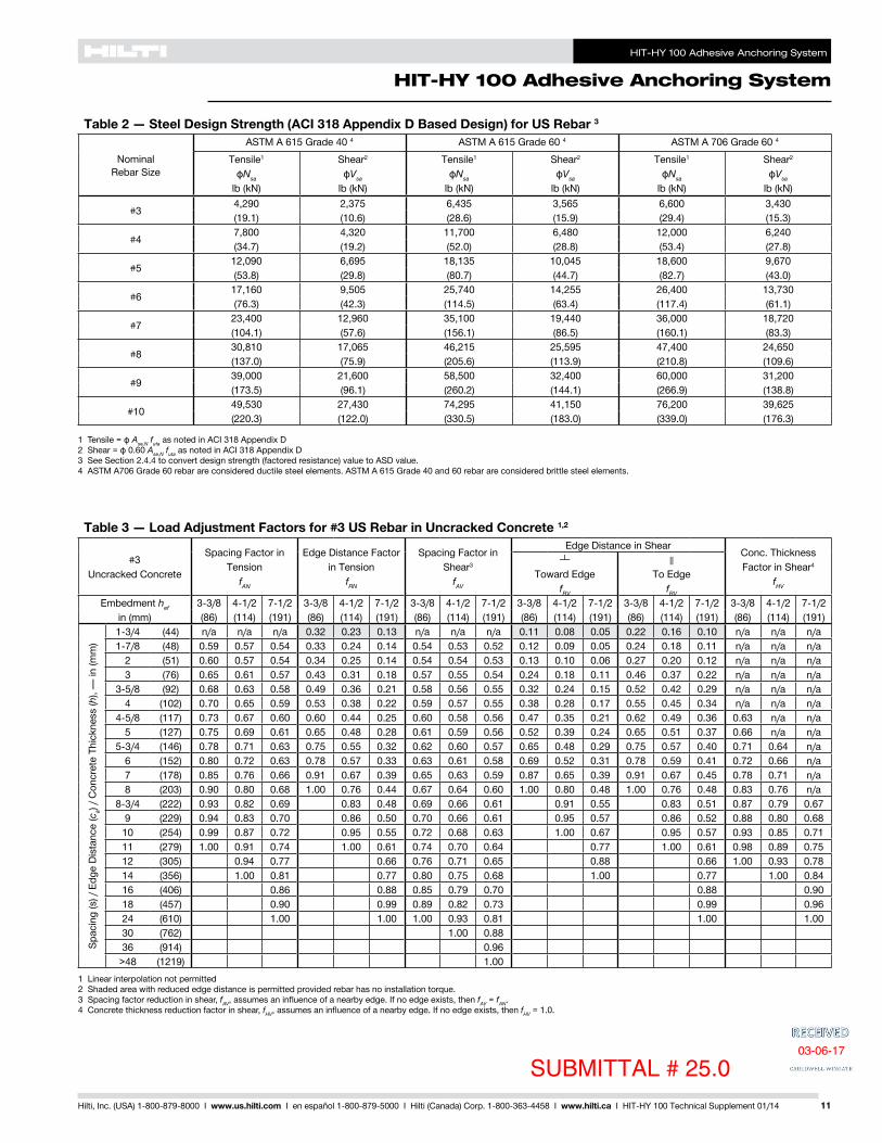
HIT-HY 100 Adhesive Anchoring System
HIT-HY 100 Adhesive Anchoring System
11Hilti Inc (USA) 1-800-879-8000 I wwwushilticom I en espantildeol 1-800-879-5000 I Hilti (Canada) Corp 1-800-363-4458 I wwwhiltica I HIT-HY 100 Technical Supplement 0114
Table 2 mdash Steel Design Strength (ACI 318 Appendix D Based Design) for US Rebar 3
NominalRebar Size
ASTM A 615 Grade 40 4 ASTM A 615 Grade 60 4 ASTM A 706 Grade 60 4 Tensile1
ϕNsa
lb (kN)
Shear2
ϕVsa
lb (kN)
Tensile1
ϕNsa
lb (kN)
Shear2
ϕVsa
lb (kN)
Tensile1
ϕNsa
lb (kN)
Shear2
ϕVsa
lb (kN)
34290 2375 6435 3565 6600 3430(191) (106) (286) (159) (294) (153)
47800 4320 11700 6480 12000 6240(347) (192) (520) (288) (534) (278)
512090 6695 18135 10045 18600 9670(538) (298) (807) (447) (827) (430)
617160 9505 25740 14255 26400 13730(763) (423) (1145) (634) (1174) (611)
723400 12960 35100 19440 36000 18720(1041) (576) (1561) (865) (1601) (833)
830810 17065 46215 25595 47400 24650(1370) (759) (2056) (1139) (2108) (1096)
939000 21600 58500 32400 60000 31200(1735) (961) (2602) (1441) (2669) (1388)
1049530 27430 74295 41150 76200 39625(2203) (1220) (3305) (1830) (3390) (1763)
1 Tensile = ϕ AseN futa as noted in ACI 318 Appendix D2 Shear = ϕ 060 AseN futa as noted in ACI 318 Appendix D3 See Section 244 to convert design strength (factored resistance) value to ASD value4 ASTM A706 Grade 60 rebar are considered ductile steel elements ASTM A 615 Grade 40 and 60 rebar are considered brittle steel elements
Table 3 mdash Load Adjustment Factors for 3 US Rebar in Uncracked Concrete 12
3Uncracked Concrete
Spacing Factor in Tension
fAN
Edge Distance Factor in Tension
fRN
Spacing Factor in Shear3
fAV
Edge Distance in ShearConc Thickness Factor in Shear4
fHV
Toward Edge
fRV
To Edge
fRV
Embedment hef in (mm)
3-38 4-12 7-12 3-38 4-12 7-12 3-38 4-12 7-12 3-38 4-12 7-12 3-38 4-12 7-12 3-38 4-12 7-12(86) (114) (191) (86) (114) (191) (86) (114) (191) (86) (114) (191) (86) (114) (191) (86) (114) (191)
Spac
ing
(s)
Edg
e D
ista
nce
(ca)
Con
cret
e Th
ickn
ess
(h)
mdash in
(mm
)
1-34 (44) na na na 032 023 013 na na na 011 008 005 022 016 010 na na na1-78 (48) 059 057 054 033 024 014 054 053 052 012 009 005 024 018 011 na na na
2 (51) 060 057 054 034 025 014 054 054 053 013 010 006 027 020 012 na na na3 (76) 065 061 057 043 031 018 057 055 054 024 018 011 046 037 022 na na na
3-58 (92) 068 063 058 049 036 021 058 056 055 032 024 015 052 042 029 na na na4 (102) 070 065 059 053 038 022 059 057 055 038 028 017 055 045 034 na na na
4-58 (117) 073 067 060 060 044 025 060 058 056 047 035 021 062 049 036 063 na na5 (127) 075 069 061 065 048 028 061 059 056 052 039 024 065 051 037 066 na na
5-34 (146) 078 071 063 075 055 032 062 060 057 065 048 029 075 057 040 071 064 na6 (152) 080 072 063 078 057 033 063 061 058 069 052 031 078 059 041 072 066 na7 (178) 085 076 066 091 067 039 065 063 059 087 065 039 091 067 045 078 071 na8 (203) 090 080 068 100 076 044 067 064 060 100 080 048 100 076 048 083 076 na
8-34 (222) 093 082 069 083 048 069 066 061 091 055 083 051 087 079 0679 (229) 094 083 070 086 050 070 066 061 095 057 086 052 088 080 068
10 (254) 099 087 072 095 055 072 068 063 100 067 095 057 093 085 07111 (279) 100 091 074 100 061 074 070 064 077 100 061 098 089 07512 (305) 094 077 066 076 071 065 088 066 100 093 07814 (356) 100 081 077 080 075 068 100 077 100 08416 (406) 086 088 085 079 070 088 09018 (457) 090 099 089 082 073 099 09624 (610) 100 100 100 093 081 100 10030 (762) 100 08836 (914) 096
gt48 (1219) 1001 Linear interpolation not permitted2 Shaded area with reduced edge distance is permitted provided rebar has no installation torque3 Spacing factor reduction in shear fAV assumes an influence of a nearby edge If no edge exists then fAV = fAN4 Concrete thickness reduction factor in shear fHV assumes an influence of a nearby edge If no edge exists then fHV = 10
SUBMITTAL 25003-06-17
HIT-HY 100 Adhesive Anchoring System
HIT-HY 100 Adhesive Anchoring System
12 Hilti Inc (USA) 1-800-879-8000 I wwwushilticom I en espantildeol 1-800-879-5000 I Hilti (Canada) Corp 1-800-363-4458 I wwwhiltica I HIT-HY 100 Technical Supplement 0114
Table 4 mdash Load Adjustment Factors for 4 US Rebar in Uncracked Concrete 12
4Uncracked Concrete
Spacing Factor in Tension
fAN
Edge Distance Factor in Tension
fRN
Spacing Factor in Shear3
fAV
Edge Distance in ShearConc Thickness Factor in Shear4
fHV
Toward Edge
fRV
To Edge
fRV
Embedment hef in (mm)
4-12 6 10 4-12 6 10 4-12 6 10 4-12 6 10 4-12 6 10 4-12 6 10(114) (152) (254) (114) (152) (254) (114) (152) (254) (114) (152) (254) (114) (152) (254) (114) (152) (254)
Spac
ing
(s)
Edg
e D
ista
nce
(ca)
Con
cret
e Th
ickn
ess
(h)
mdash in
(mm
) 1-34 (44) na na na 027 020 012 na na na 007 005 003 014 011 006 na na na2-12 (64) 059 057 054 032 023 014 054 053 052 012 009 005 024 018 011 na na na
3 (76) 061 058 055 035 026 015 055 054 053 016 012 007 032 024 014 na na na4 (102) 065 061 057 042 030 018 057 055 054 024 018 011 045 037 022 na na na5 (127) 069 064 058 049 036 021 058 057 055 034 026 015 051 042 031 na na na
5-34 (146) 071 066 060 055 040 023 059 058 055 042 031 019 057 046 034 061 na na6 (152) 072 067 060 057 042 024 060 058 056 045 034 020 059 047 035 062 na na7 (178) 076 069 062 067 049 029 061 059 057 056 042 025 067 052 038 067 na na
7-14 (184) 077 070 062 069 051 030 062 060 057 059 045 027 069 053 038 069 062 na8 (203) 080 072 063 076 056 033 063 061 058 069 052 031 076 057 040 072 066 na9 (229) 083 075 065 086 063 037 065 062 059 082 062 037 086 063 043 076 069 na
10 (254) 087 078 067 095 070 041 066 063 060 096 072 043 095 070 046 081 073 na11-14 (286) 092 081 069 100 078 046 068 065 061 100 086 052 100 078 050 086 078 066
12 (305) 094 083 070 084 049 070 066 061 095 057 084 052 088 080 06814 (356) 100 089 073 098 057 073 069 063 100 072 098 058 095 087 07316 (406) 094 077 100 065 076 071 065 088 100 065 100 093 07818 (457) 100 080 073 079 074 067 100 073 098 08320 (508) 083 082 083 077 069 082 100 08722 (559) 087 090 086 080 071 090 09224 (610) 090 098 089 082 073 098 09630 (762) 100 100 099 090 079 100 10036 (914) 100 098 084
gt48 (1219) 100 096
1 Linear interpolation not permitted2 Shaded area with reduced edge distance is permitted provided rebar has no installation torque3 Spacing factor reduction in shear fAV assumes an influence of a nearby edge If no edge exists then fAV = fAN4 Concrete thickness reduction factor in shear fHV assumes an influence of a nearby edge If no edge exists then fHV = 10
Table 5 mdash Load Adjustment Factors for 5 US Rebar in Uncracked Concrete 12
5Uncracked Concrete
Spacing Factor in Tension
fAN
Edge Distance Factor in Tension
fRN
Spacing Factor in Shear3
fAV
Edge Distance in ShearConc Thickness Factor in Shear4
fHV
Toward Edge
fRV
To Edge
fRV
Embedment hef in (mm)
5-58 7-12 12-12 5-58 7-12 12-12 5-58 7-12 12-12 5-58 7-12 12-12 5-58 7-12 12-12 5-58 7-12 12-12(143) (191) (318) (143) (191) (318) (143) (191) (318) (143) (191) (318) (143) (191) (318) (143) (191) (318)
Spac
ing
(s)
Edg
e D
ista
nce
(ca)
Con
cret
e Th
ickn
ess
(h)
mdash in
(mm
)
1-34 (44) na na na 025 019 011 na na na 005 004 002 010 008 005 na na na3-18 (79) 059 057 054 032 023 014 054 053 052 012 009 005 024 018 011 na na na
4 (102) 062 059 055 036 027 016 055 054 053 017 013 008 035 026 016 na na na4-58 (117) 064 060 056 039 029 017 056 055 054 022 016 010 043 033 020 na na na
5 (127) 065 061 057 041 030 018 057 055 054 024 018 011 045 037 022 na na na6 (152) 068 063 058 047 034 020 058 056 055 032 024 014 050 041 029 na na na7 (178) 071 066 059 053 039 023 059 058 055 040 030 018 055 045 034 na na na
7-18 (181) 071 066 060 054 040 023 059 058 055 041 031 019 056 046 034 061 na na8 (203) 074 068 061 061 045 026 060 059 056 049 037 022 061 049 036 065 na na9 (229) 077 070 062 068 050 029 062 060 057 059 044 026 068 053 038 068 062 na
10 (254) 080 072 063 076 056 033 063 061 058 069 052 031 076 057 040 072 066 na11 (279) 083 074 065 083 061 036 064 062 058 079 060 036 083 062 042 076 069 na12 (305) 086 077 066 091 067 039 066 063 059 091 068 041 091 067 045 079 072 na14 (356) 091 081 069 100 078 046 068 065 061 100 086 051 100 078 049 085 078 06516 (406) 097 086 071 089 052 071 067 062 100 063 089 054 091 083 07018 (457) 100 090 074 100 059 073 069 064 075 100 059 097 088 07420 (508) 094 077 065 076 071 065 088 065 100 093 07822 (559) 099 079 072 079 074 067 100 072 097 08224 (610) 100 082 078 081 076 068 078 100 08626 (660) 085 085 084 078 070 085 08928 (711) 087 091 086 080 071 091 09230 (762) 090 098 089 082 073 098 09636 (914) 098 100 097 089 077 100 100
gt48 (1219) 100 100 100 087
SUBMITTAL 250 03-06-17
HIT-HY 100 Adhesive Anchoring System
HIT-HY 100 Adhesive Anchoring System
13Hilti Inc (USA) 1-800-879-8000 I wwwushilticom I en espantildeol 1-800-879-5000 I Hilti (Canada) Corp 1-800-363-4458 I wwwhiltica I HIT-HY 100 Technical Supplement 0114
Table 6 mdash Load Adjustment Factors for 6 US Rebar in Uncracked Concrete 12
6Uncracked Concrete
Spacing Factor in Tension
fAN
Edge Distance Factor in Tension
fRN
Spacing Factor in Shear3
fAV
Edge Distance in Shear Conc Thickness Factor in Shear4
fHV
Toward Edge
fRV
To Edge
fRV
Embedment hef in (mm)
6-34 9 15 6-34 9 15 6-34 9 15 6-34 9 15 6-34 9 15 6-34 9 15(171) (229) (381) (171) (229) (381) (171) (229) (381) (171) (229) (381) (171) (229) (381) (171) (229) (381)
Spac
ing
(s)
Edg
e D
ista
nce
(ca)
Con
cret
e Th
ickn
ess
(h)
mdash in
(mm
)
1-34 (44) na na na 024 018 010 na na na 004 003 002 008 006 003 na na na3-34 (95) 059 057 054 032 023 014 054 053 052 012 009 005 024 018 011 na na na
4 (102) 060 057 054 033 024 014 054 054 053 013 010 006 026 019 012 na na na5 (127) 062 059 056 037 027 016 055 054 053 018 014 008 036 027 016 na na na
5-14 (133) 063 060 056 038 028 016 056 055 053 020 015 009 039 029 018 na na na6 (152) 065 061 057 041 030 018 056 055 054 024 018 011 045 036 021 na na na7 (178) 067 063 058 046 034 020 057 056 054 030 023 014 049 041 027 na na na8 (203) 070 065 059 051 037 022 059 057 055 037 028 017 053 044 033 na na na
8-12 (216) 071 066 059 054 039 023 059 057 055 040 030 018 056 045 034 060 na na9 (229) 072 067 060 057 042 024 060 058 056 044 033 020 058 047 035 062 na na
10 (254) 075 069 061 063 046 027 061 059 056 051 039 023 063 050 037 065 na na10-34 (273) 077 070 062 068 050 029 061 059 057 057 043 026 068 053 038 068 062 na
12 (305) 080 072 063 076 056 033 063 061 058 067 051 030 076 057 040 072 065 na14 (356) 085 076 066 088 065 038 065 062 059 085 064 038 088 065 044 077 070 na16 (406) 090 080 068 100 074 043 067 064 060 100 078 047 100 074 048 083 075 na
16-34 (425) 091 081 069 078 045 068 065 061 083 050 078 049 085 077 06518 (457) 094 083 070 083 049 069 066 061 093 056 083 052 088 080 06720 (508) 099 087 072 093 054 071 068 063 100 065 093 056 092 084 07122 (559) 100 091 074 100 060 074 069 064 075 100 060 097 088 07424 (610) 094 077 065 076 071 065 086 065 100 092 07826 (660) 098 079 071 078 073 066 097 071 096 08128 (711) 100 081 076 080 075 068 100 076 099 08430 (762) 083 081 082 076 069 081 100 08736 (914) 090 098 088 082 073 098 095
gt48 (1219) 100 100 100 092 080 100 100
1 Linear interpolation not permitted2 Shaded area with reduced edge distance is permitted provided rebar has no installation torque3 Spacing factor reduction in shear fAV assumes an influence of a nearby edge If no edge exists then fAV = fAN4 Concrete thickness reduction factor in shear fHV assumes an influence of a nearby edge If no edge exists then fHV = 10
Table 7 mdash Load Adjustment Factors for 7 US Rebar in Uncracked Concrete 12
7Uncracked Concrete
Spacing Factor in Tension
fAN
Edge Distance Factor in Tension
fRN
Spacing Factor in Shear3
fAV
Edge Distance in Shear Conc Thickness Factor in Shear4
fHV
Toward Edge
fRV
To Edge
fRV
Embedment hef in (mm)
7-78 10-12 17-12 7-78 10-12 17-12 7-78 10-12 17-12 7-78 10-12 17-12 7-78 10-12 17-12 7-78 10-12 17-12(200) (267) (445) (200) (267) (445) (200) (267) (445) (200) (267) (445) (200) (267) (445) (200) (267) (445)
Spac
ing
(s)
Edg
e D
ista
nce
(ca)
Con
cret
e Th
ickn
ess
(h)
mdash in
(mm
)
1-34 (44) na na na 023 017 010 na na na 003 002 001 006 004 002 na na na4-38 (111) 059 057 054 032 023 014 054 053 052 011 008 005 022 016 010 na na na
5 (127) 061 058 055 034 025 015 054 054 053 013 010 006 027 020 012 na na na5-12 (140) 062 059 055 036 026 015 055 054 053 015 012 007 031 023 014 na na na
6 (152) 063 060 056 037 028 016 055 054 053 018 013 008 035 026 016 na na na7 (178) 065 061 057 041 030 018 056 055 054 022 017 010 044 033 020 na na na8 (203) 067 063 058 045 033 019 057 056 054 027 020 012 048 040 024 na na na9 (229) 069 064 059 049 036 021 058 056 055 032 024 014 052 043 029 na na na
9-78 (251) 071 066 059 053 039 023 059 057 055 037 028 017 056 045 033 059 na na10 (254) 071 066 060 054 040 023 059 057 055 038 028 017 056 045 034 059 na na11 (279) 073 067 060 059 044 026 060 058 056 044 033 020 060 048 036 062 na na12 (305) 075 069 061 065 048 028 060 059 056 050 037 022 065 051 037 065 na na
12-12 (318) 076 070 062 067 050 029 061 059 056 053 040 024 067 053 038 066 060 na14 (356) 080 072 063 075 055 033 062 060 057 062 047 028 075 057 040 070 063 na16 (406) 084 075 065 086 063 037 064 061 058 076 057 034 086 063 043 075 068 na18 (457) 088 079 067 097 071 042 066 063 059 091 068 041 097 071 047 079 072 na
19-12 (495) 091 081 069 100 077 045 067 064 060 100 077 046 100 077 049 082 075 06320 (508) 092 082 069 079 046 067 064 060 080 048 079 050 083 076 06422 (559) 097 085 071 087 051 069 066 061 092 055 087 053 088 079 06724 (610) 100 088 073 095 056 071 067 062 100 063 095 057 091 083 07026 (660) 091 075 100 060 073 069 063 071 100 061 095 086 07328 (711) 094 077 065 074 070 064 080 065 099 090 07630 (762) 098 079 070 076 072 065 088 070 100 093 07836 (914) 100 084 084 081 076 068 100 084 100 086
gt48 (1219) 096 100 092 084 075 100 099
SUBMITTAL 250 03-06-17
HIT-HY 100 Adhesive Anchoring System
HIT-HY 100 Adhesive Anchoring System
14 Hilti Inc (USA) 1-800-879-8000 I wwwushilticom I en espantildeol 1-800-879-5000 I Hilti (Canada) Corp 1-800-363-4458 I wwwhiltica I HIT-HY 100 Technical Supplement 0114
Table 8 mdash Load Adjustment Factors for 8 US Rebar in Uncracked Concrete 12
8Uncracked Concrete
Spacing Factor in Tension
fAN
Edge Distance Factor in Tension
fRN
Spacing Factor in Shear3
fAV
Edge Distance in Shear Conc Thickness Factor in Shear4
fHV
Toward Edge
fRV
To Edge
fRV
Embedment hef in (mm)
9 12 20 9 12 20 9 12 20 9 12 20 9 12 20 9 12 20(229) (305) (508) (229) (305) (508) (229) (305) (508) (229) (305) (508) (229) (305) (508) (229) (305) (508)
Spac
ing
(s)
Edg
e D
ista
nce
(ca)
Con
cret
e Th
ickn
ess
(h)
mdash in
(mm
)
1-34 (44) na na na 023 017 010 na na na 002 002 001 005 003 002 na na na5 (127) 059 057 054 032 023 014 054 053 052 011 008 005 022 015 009 na na na6 (152) 061 058 055 035 025 015 055 054 053 014 010 006 029 020 012 na na na
6-14 (159) 062 059 055 035 026 015 055 054 053 015 011 006 030 021 013 na na na7 (178) 063 060 056 038 028 016 055 054 053 018 013 008 036 025 015 na na na8 (203) 065 061 057 041 030 018 056 055 053 022 015 009 044 031 019 na na na9 (229) 067 063 058 045 033 019 057 055 054 026 018 011 048 037 022 na na na
10 (254) 069 064 058 048 035 021 058 056 054 031 022 013 051 042 026 na na na11 (279) 070 065 059 052 038 022 058 057 055 035 025 015 055 044 030 na na na
11-14 (286) 071 066 059 053 039 023 059 057 055 037 026 016 055 045 031 058 na na12 (305) 072 067 060 057 042 024 059 057 055 040 028 017 058 047 034 060 na na13 (330) 074 068 061 061 045 026 060 058 056 046 032 019 062 049 036 063 na na14 (356) 076 069 062 066 049 028 061 058 056 051 036 022 066 052 038 065 na na
14-14 (362) 076 070 062 067 049 029 061 059 056 052 037 022 067 052 038 066 059 na16 (406) 080 072 063 075 055 033 062 060 057 062 044 026 075 057 040 070 062 na18 (457) 083 075 065 085 062 037 064 061 058 074 052 031 085 062 043 074 066 na20 (508) 087 078 067 094 069 041 065 062 059 087 061 037 094 069 046 078 069 na22 (559) 091 081 068 100 076 045 067 063 059 100 071 042 100 076 049 082 073 na
22-14 (565) 091 081 069 077 045 067 063 060 072 043 077 049 082 073 06224 (610) 094 083 070 083 049 068 064 060 081 048 083 052 085 076 06426 (660) 098 086 072 090 053 070 066 061 091 054 090 055 089 079 06728 (711) 100 089 073 097 057 071 067 062 100 061 097 058 092 082 06930 (762) 092 075 100 061 073 068 063 068 100 061 095 085 07236 (914) 100 080 073 077 072 065 089 073 100 093 078
gt48 (1219) 090 098 086 079 071 100 098 100 091
1 Linear interpolation not permitted2 Shaded area with reduced edge distance is permitted provided rebar has no installation torque3 Spacing factor reduction in shear fAV assumes an influence of a nearby edge If no edge exists then fAV = fAN4 Concrete thickness reduction factor in shear fHV assumes an influence of a nearby edge If no edge exists then fHV = 10
Table 9 mdash Load Adjustment Factors for 9 US Rebar in Uncracked Concrete 12
9Uncracked Concrete
Spacing Factor in Tension
fAN
Edge Distance Factor in Tension
fRN
Spacing Factor in Shear3
fAV
Edge Distance in Shear Conc Thickness Factor in Shear4
fHV
Toward Edge
fRV
To Edge
fRV
Embedment hef in (mm)
10-18 13-12 22-12 10-18 13-12 22-12 10-18 13-12 22-12 10-18 13-12 22-12 10-18 13-12 22-12 10-18 13-12 22-12(257) (343) (572) (257) (343) (572) (257) (343) (572) (257) (343) (572) (257) (343) (572) (257) (343) (572)
Spac
ing
(s)
Edg
e D
ista
nce
(ca)
Con
cret
e Th
ickn
ess
(h)
mdash in
(mm
)
1-34 (44) na na na 022 016 010 na na na 002 001 001 004 003 002 na na na5-58 (143) 059 057 054 032 023 014 054 053 052 011 007 004 022 014 009 na na na
6 (152) 060 057 054 033 024 014 054 053 052 012 008 005 024 016 010 na na na7 (178) 062 059 055 036 026 015 055 054 053 015 010 006 030 020 012 na na na
7-14 (184) 062 059 055 036 027 016 055 054 053 016 011 006 032 021 013 na na na8 (203) 063 060 056 038 028 017 055 054 053 018 012 007 037 024 015 na na na9 (229) 065 061 057 041 030 018 056 055 053 022 015 009 044 029 018 na na na
10 (254) 066 062 057 045 033 019 057 055 054 026 017 010 048 034 021 na na na11 (279) 068 064 058 048 035 020 057 056 054 030 020 012 051 039 024 na na na12 (305) 070 065 059 051 037 022 058 056 054 034 022 013 054 044 027 na na na
12-78 (327) 071 066 060 054 040 023 059 057 055 038 025 015 056 046 030 059 na na13 (330) 071 066 060 055 040 024 059 057 055 038 025 015 057 046 030 059 na na14 (356) 073 067 060 059 043 025 059 057 055 043 028 017 060 048 034 061 na na16 (406) 076 070 062 067 050 029 061 058 056 052 035 021 067 053 038 066 na na
16-14 (413) 077 070 062 069 050 029 061 058 056 053 035 021 069 053 038 066 058 na18 (457) 080 072 063 076 056 033 062 059 057 062 041 025 076 057 040 070 061 na20 (508) 083 075 065 084 062 036 063 060 057 073 048 029 084 062 043 073 064 na22 (559) 086 077 066 093 068 040 065 061 058 084 056 034 093 068 045 077 067 na24 (610) 090 080 068 100 074 043 066 062 059 096 064 038 100 074 048 080 070 na
25-14 (641) 092 081 069 078 046 067 063 059 100 069 041 078 049 083 072 06126 (660) 093 082 069 080 047 068 063 060 072 043 080 050 084 073 06228 (711) 096 085 071 087 051 069 064 060 080 048 087 053 087 076 06430 (762) 099 087 072 093 054 070 065 061 089 053 093 056 090 079 06636 (914) 100 094 077 100 065 074 068 063 100 070 100 065 099 086 073
gt48 (1219) 100 086 087 082 075 068 100 087 100 099 084
SUBMITTAL 250 03-06-17
HIT-HY 100 Adhesive Anchoring System
HIT-HY 100 Adhesive Anchoring System
15Hilti Inc (USA) 1-800-879-8000 I wwwushilticom I en espantildeol 1-800-879-5000 I Hilti (Canada) Corp 1-800-363-4458 I wwwhiltica I HIT-HY 100 Technical Supplement 0114
Table 10 mdash Load Adjustment Factors for 10 US Rebar in Uncracked Concrete 12
10Uncracked Concrete
Spacing Factor in Tension
fAN
Edge Distance Factor in Tension
fRN
Spacing Factor in Shear3
fAV
Edge Distance in ShearConc Thickness Factor in Shear4
fHV
Toward Edge
fRV
To Edge
fRV
Embedment hef in (mm)
11-14 15 25 11-14 15 25 11-14 15 25 11-14 15 25 11-14 15 25 11-14 15 25(286) (381) (635) (286) (381) (635) (286) (381) (635) (286) (381) (635) (286) (381) (635) (286) (381) (635)
Spac
ing
(s)
Edg
e D
ista
nce
(ca)
Con
cret
e Th
ickn
ess
(h)
mdash in
(mm
) 1-34 (44) na na na 022 016 009 na na na 002 001 001 003 002 001 na na na6-14 (159) 059 057 054 032 023 014 054 053 052 011 007 004 022 014 008 na na na
7 (178) 060 058 055 034 025 014 054 053 052 013 008 005 026 017 010 na na na8 (203) 062 059 055 036 027 016 055 054 053 016 010 006 031 020 012 na na na9 (229) 063 060 056 039 028 017 055 054 053 019 012 007 038 024 014 na na na
10 (254) 065 061 057 041 030 018 056 055 053 022 014 008 044 029 017 na na na11 (279) 066 062 057 044 032 019 057 055 053 025 016 010 047 033 019 na na na12 (305) 068 063 058 047 034 020 057 055 054 029 019 011 050 038 022 na na na13 (330) 069 064 059 050 037 021 058 056 054 033 021 012 053 042 025 na na na14 (356) 071 066 059 053 039 023 059 056 054 036 024 014 055 045 028 na na na
14-14 (362) 071 066 060 054 040 023 059 056 055 037 024 014 056 046 028 059 na na15 (381) 072 067 060 057 042 024 059 057 055 040 026 015 058 047 031 060 na na16 (406) 074 068 061 061 045 026 060 057 055 045 029 017 061 049 034 062 na na17 (432) 075 069 061 064 047 028 060 058 055 049 032 018 064 051 037 064 na na18 (457) 077 070 062 068 050 029 061 058 056 053 035 020 068 053 038 066 057 na20 (508) 080 072 063 076 056 033 062 059 056 062 040 024 076 057 040 070 060 na22 (559) 083 074 065 083 061 036 063 060 057 072 047 027 083 062 042 073 063 na24 (610) 086 077 066 091 067 039 065 061 058 082 053 031 091 067 045 076 066 na26 (660) 089 079 067 099 072 042 066 062 058 092 060 035 099 072 047 079 069 na28 (711) 091 081 069 100 078 046 067 063 059 100 067 039 100 078 049 082 071 06030 (762) 094 083 070 083 049 068 064 060 074 043 083 052 085 074 06236 (914) 100 090 074 100 059 072 066 061 098 057 100 059 094 081 068
gt48 (1219) 100 082 078 079 072 065 100 087 078 100 094 078
1 Linear interpolation not permitted2 Shaded area with reduced edge distance is permitted provided rebar has no installation torque3 Spacing factor reduction in shear fAV assumes an influence of a nearby edge If no edge exists then fAV = fAN4 Concrete thickness reduction factor in shear fHV assumes an influence of a nearby edge If no edge exists then fHV = 10
SUBMITTAL 25003-06-17
HIT-HY 100 Adhesive Anchoring System
HIT-HY 100 Adhesive Anchoring System
16 Hilti Inc (USA) 1-800-879-8000 I wwwushilticom I en espantildeol 1-800-879-5000 I Hilti (Canada) Corp 1-800-363-4458 I wwwhiltica I HIT-HY 100 Technical Supplement 0114
Table 11 mdash Hilti HIT-HY 100 Adhesive Factored Resistance with Concrete Bond Failure for Canadian Rebar in Uncracked Concrete 12345678
NominalRebar Size
EffectiveEmbedment
Depthmm
Tension mdash Nr Shear mdash Vr
f´c = 20 MPa
(kN)
f´c = 25 MPa
(kN)
f´c = 30 MPa
(kN)
f´c = 35 MPa
(kN)
f´c = 40 MPa
(kN)
f´c = 20 MPa
(kN)
f´c = 25 MPa
(kN)
f´c = 30 MPa
(kN)
f´c = 35 MPa
(kN)
f´c = 40 MPa
(kN)
10 M115 223 223 223 236 236 480 480 480 509 509180 349 349 349 370 370 751 751 751 797 797226 438 438 438 464 464 944 944 944 1000 1000
15 M145 398 398 398 422 422 857 857 857 909 909250 686 686 686 727 727 1478 1478 1478 1566 1566320 878 878 878 931 931 1892 1892 1892 2005 2005
20 M200 669 669 669 709 709 1441 1441 1441 1527 1527355 1187 1187 1187 1259 1259 2558 2558 2558 2711 2711390 1304 1304 1304 1383 1383 2810 2810 2810 2978 2978
25 M230 994 994 994 1054 1054 2141 2141 2141 2270 2270405 1751 1751 1751 1856 1856 3771 3771 3771 3997 3997504 2179 2179 2179 2309 2309 4692 4692 4692 4974 4974
30 M260 1128 1128 1128 1196 1196 2625 2872 2872 3044 3044455 1975 1975 1975 2093 2093 5026 5026 5026 5328 5328598 2595 2595 2595 2751 2751 6606 6606 6606 7002 7002
1 See Section 24 for explanation on development of load values2 See Section 244 to convert design strength (factored resistance) value to ASD value3 Linear interpolation between embedment depths and concrete compressive strengths is not permitted4 Apply spacing edge distance and concrete thickness factors in tables 13 - 17 as necessary Compare to the steel values in table 12
The lesser of the values is to be used for the design5 Data is for temperature range A Max short term temperature = 104deg F (40deg C) max long term temperature = 75deg F (24deg C)
For temperature range B Max short term temperature = 176deg F (80deg C) max long term temperature = 122deg F (50deg C) multiply above value by 083 For temperature range C Max short term temperature = 248deg F (120deg C) max long term temperature = 162deg F (72deg C) multiply above value by 048 Short term elevated concrete temperatures are those that occur over brief intervals eg as a result of diurnal cycling Long term concrete temperatures are roughly constant over significant periods of time
6 Tabular values are for dry and water-saturated concrete conditions7 Tabular values are for short term loads only For sustained loads including overhead use see Section 2458 Tabular values are for normal weight concrete only For lightweight concrete multiply design strength (factored resistance) by λa as follows
For sand-lightweight λa = 051 For all-lightweight λa = 045
Table 12 mdash Steel Factored Resistance (CSA A233 Annex D Based Design) for Canadian Rebar 3
NominalRebar Size
CSA-G3018 Grade 400 4 Tensile1
Nsr
Shear2
Vsr
10 M 321 17915 M 646 35920 M 961 53625 M 1607 89230 M 2261 1257
1 Tensile = Ase ϕs fut R as noted in CSA A233 Annex D2 Shear = Ase ϕs 060 fut R as noted in CSA A233 Annex D3 See Section 244 to convert factored resistance value to ASD value4 CSA-G3018 Grade 400 rebar are considered brittle steel elements
SUBMITTAL 250 03-06-17
HIT-HY 100 Adhesive Anchoring System
HIT-HY 100 Adhesive Anchoring System
17Hilti Inc (USA) 1-800-879-8000 I wwwushilticom I en espantildeol 1-800-879-5000 I Hilti (Canada) Corp 1-800-363-4458 I wwwhiltica I HIT-HY 100 Technical Supplement 0114
Table 13 mdash Load Adjustment Factors for 10 M Canadian Rebar in Uncracked Concrete 12
10 MUncracked Concrete
Spacing Factor in Tension
fAN
Edge Distance Factor in Tension
fRN
Spacing Factor in Shear3
fAV
Edge Distance in ShearConc Thickness Factor in Shear4
fHV
Toward Edge
fRV
To Edge
fRV
Embedment hef mm
115 180 226 115 180 226 115 180 226 115 180 226 115 180 226 115 180 226
Spac
ing
(s)
Edg
e D
ista
nce
(ca)
Con
cret
e Th
ickn
ess
(h)
mdash in
(mm
)
45 na na na 025 016 012 na na na 008 005 004 016 010 008 na na na50 057 055 054 027 017 013 053 053 052 010 006 005 019 012 010 na na na75 061 057 056 033 020 016 055 054 053 018 011 009 035 022 018 na na na
100 064 059 057 039 024 019 057 055 054 027 017 014 045 035 028 na na na125 068 062 059 047 029 023 059 056 056 038 024 019 051 039 035 na na na150 072 064 061 056 035 028 060 058 057 050 032 025 058 042 037 065 na na175 075 066 063 066 041 032 062 059 058 063 040 032 066 046 040 070 na na200 079 069 065 075 047 037 064 060 059 076 049 039 075 051 043 075 na na225 083 071 067 085 052 041 066 062 060 091 058 046 085 055 047 079 068 na250 086 073 068 094 058 046 067 063 061 100 068 054 094 059 050 083 072 na275 090 075 070 100 064 051 069 064 062 079 063 100 064 053 088 075 070300 093 078 072 070 055 071 066 063 090 071 070 057 091 079 073325 097 080 074 076 060 073 067 064 100 081 076 060 095 082 076350 100 082 076 082 064 074 068 066 090 082 064 099 085 079375 085 078 087 069 076 069 067 100 087 069 100 088 082400 087 079 093 074 078 071 068 093 074 091 084450 092 083 100 083 081 073 070 100 083 096 089500 096 087 092 085 076 072 092 100 094550 100 091 100 088 078 074 100 099600 094 092 081 077 100700 100 099 086 081800 100 091 0861000 100 094
gt1200 100
1 Linear interpolation not permitted2 Shaded area with reduced edge distance is permitted provided rebar has no installation torque3 Spacing factor reduction in shear fAV assumes an influence of a nearby edge If no edge exists then fAV = fAN4 Concrete thickness reduction factor in shear fHV assumes an influence of a nearby edge If no edge exists then fHV = 10
Table 14 mdash Load Adjustment Factors for 15 M Canadian Rebar in Uncracked Concrete 12
15 MUncracked Concrete
Spacing Factor in Tension
fAN
Edge Distance Factor in Tension
fRN
Spacing Factor in Shear3
fAV
Edge Distance in ShearConc Thickness Factor in Shear4
fHV
Toward Edge
fRV
To Edge
fRV
Embedment hef mm
145 250 320 145 250 320 145 250 320 145 250 320 145 250 320 145 250 320
Spac
ing
(s)
Edg
e D
ista
nce
(ca)
Con
cret
e Th
ickn
ess
(h)
mdash in
(mm
)
45 na na na 025 014 011 na na na 005 003 002 011 006 005 na na na75 059 055 054 030 017 013 054 053 052 012 007 005 023 014 011 na na na
100 061 057 055 035 020 015 055 054 053 018 010 008 036 021 016 na na na125 064 058 057 040 023 018 057 055 054 025 015 011 044 029 023 na na na150 067 060 058 045 026 020 058 056 055 033 019 015 049 036 030 na na na175 070 062 059 051 029 022 059 056 055 042 024 019 054 038 034 061 na na200 073 063 060 058 033 026 061 057 056 051 030 023 060 041 036 065 na na225 076 065 062 066 037 029 062 058 057 061 035 028 066 044 038 069 na na250 079 067 063 073 041 032 063 059 058 071 041 032 073 046 040 073 na na275 082 068 064 080 045 035 065 060 059 082 048 037 080 049 042 076 na na300 084 070 066 088 050 038 066 061 059 094 054 042 088 052 044 080 067 na325 087 072 067 095 054 042 067 062 060 100 061 048 095 056 047 083 069 na350 090 073 068 100 058 045 069 063 061 068 053 100 059 049 086 072 066375 093 075 070 062 048 070 064 062 076 059 062 051 089 074 069400 096 077 071 066 051 071 065 063 084 065 066 054 092 077 071450 100 080 073 074 058 074 067 064 100 078 074 058 098 082 075500 083 076 083 064 077 068 066 091 083 064 100 086 079550 087 079 091 070 079 070 067 100 091 070 090 083600 090 081 099 077 082 072 069 099 077 094 087650 093 084 100 083 085 074 070 100 083 098 090700 097 086 090 087 076 072 090 100 094800 100 092 100 093 080 075 100 100
1000 100 100 087 081gt1200 094 088
SUBMITTAL 250
03-06-17
HIT-HY 100 Adhesive Anchoring System
HIT-HY 100 Adhesive Anchoring System
18 Hilti Inc (USA) 1-800-879-8000 I wwwushilticom I en espantildeol 1-800-879-5000 I Hilti (Canada) Corp 1-800-363-4458 I wwwhiltica I HIT-HY 100 Technical Supplement 0114
Table 15 mdash Load Adjustment Factors for 20 M Canadian Rebar in Uncracked Concrete 12
20 MUncracked Concrete
Spacing Factor in Tension
fAN
Edge Distance Factor in Tension
fRN
Spacing Factor in Shear3
fAV
Edge Distance in ShearConc Thickness Factor in Shear4
fHV
Toward Edge
fRV
To Edge
fRV
Embedment hef mm
200 355 390 200 355 390 200 355 390 200 355 390 200 355 390 200 355 390
Spac
ing
(s)
Edg
e D
ista
nce
(ca)
Con
cret
e Th
ickn
ess
(h)
mdash in
(mm
)
45 na na na 021 011 010 na na na 003 002 002 007 004 004 na na na100 058 055 054 028 015 014 054 053 053 011 006 006 023 013 012 na na na125 060 056 055 032 017 016 055 053 053 016 009 008 032 018 016 na na na150 063 057 056 036 019 018 056 054 054 021 012 011 041 024 022 na na na175 065 058 057 039 021 019 057 055 054 027 015 014 045 030 027 na na na200 067 059 059 044 024 022 058 055 055 032 018 017 049 035 033 na na na225 069 061 060 049 026 024 059 056 056 039 022 020 052 037 035 na na na250 071 062 061 054 029 027 060 057 056 045 026 023 056 039 037 na na na275 073 063 062 059 032 029 061 057 057 052 029 027 060 041 038 066 na na300 075 064 063 065 035 032 062 058 058 060 034 031 065 042 040 069 na na325 077 065 064 070 038 035 063 059 058 067 038 034 070 044 042 071 na na350 079 066 065 075 041 037 064 059 059 075 042 038 075 046 044 074 na na375 081 068 066 081 044 040 065 060 059 083 047 043 081 049 046 077 na na400 083 069 067 086 047 043 066 061 060 092 052 047 086 051 047 079 na na450 088 071 069 097 053 048 068 062 061 100 062 056 097 055 051 084 069 067500 092 073 071 100 059 053 070 063 063 072 066 100 059 055 089 073 071550 096 076 074 065 059 072 065 064 083 076 065 059 093 077 074600 100 078 076 070 064 074 066 065 095 086 070 064 097 080 078650 081 078 076 069 076 067 066 100 097 076 069 100 084 081700 083 080 082 074 078 069 068 100 082 074 087 084800 088 084 094 085 081 071 070 094 085 093 090
1000 097 093 100 100 089 077 075 100 100 100 1001200 100 100 097 082 080
gt1500 100 090 088
1 Linear interpolation not permitted2 Shaded area with reduced edge distance is permitted provided rebar has no installation torque3 Spacing factor reduction in shear fAV assumes an influence of a nearby edge If no edge exists then fAV = fAN4 Concrete thickness reduction factor in shear fHV assumes an influence of a nearby edge If no edge exists then fHV = 10
Table 16 mdash Load Adjustment Factors for 25 M Canadian Rebar in Uncracked Concrete 12
25 MUncracked Concrete
Spacing Factor in Tension
fAN
Edge Distance Factor in Tension
fRN
Spacing Factor in Shear3
fAV
Edge Distance in ShearConc Thickness Factor in Shear4
fHV
Toward Edge
fRV
To Edge
fRV
Embedment hef mm
230 405 504 230 405 504 230 405 504 230 405 504 230 405 504 230 405 504
Spac
ing
(s)
Edg
e D
ista
nce
(ca)
Con
cret
e Th
ickn
ess
(h)
mdash in
(mm
)
45 na na na 022 012 010 na na na 002 001 001 005 003 002 na na na125 059 055 054 031 017 014 054 053 052 011 006 005 022 012 010 na na na150 061 056 055 035 019 015 055 053 053 014 008 006 028 016 013 na na na175 063 057 056 038 021 016 055 054 053 018 010 008 036 020 016 na na na200 064 058 057 041 022 018 056 054 054 022 012 010 044 025 020 na na na225 066 059 057 045 024 019 057 055 054 026 015 012 048 030 024 na na na250 068 060 058 048 026 021 058 055 054 030 017 014 052 035 028 na na na275 070 061 059 052 028 023 058 056 055 035 020 016 055 038 032 na na na300 072 062 060 057 031 025 059 056 055 040 023 018 058 040 036 060 na na325 074 063 061 061 034 027 060 057 056 045 026 021 062 041 037 063 na na350 075 064 062 066 036 029 061 057 056 050 029 023 066 043 038 065 na na375 077 065 062 071 039 031 061 058 057 056 032 026 071 045 039 067 na na400 079 066 063 076 041 033 062 058 057 062 035 028 076 047 041 070 na na450 083 069 065 085 046 037 064 059 058 074 042 034 085 050 044 074 na na500 086 071 067 094 052 041 065 060 059 086 049 039 094 054 046 078 064 na550 090 073 068 100 057 045 067 061 060 099 056 045 100 058 049 081 067 na600 093 075 070 062 049 068 062 061 100 064 052 062 052 085 070 066650 097 077 071 067 053 070 063 062 073 058 067 055 089 073 068700 100 079 073 072 058 071 064 063 081 065 072 059 092 076 071750 081 075 077 062 073 066 063 090 072 077 062 095 079 073800 083 076 083 066 074 067 064 099 080 083 066 098 081 076
1000 091 083 100 082 080 071 068 100 100 100 082 100 091 0851200 099 090 099 086 075 071 099 100 093
gt1500 100 100 100 095 081 077 100 100
SUBMITTAL 250
03-06-17
HIT-HY 100 Adhesive Anchoring System
HIT-HY 100 Adhesive Anchoring System
19Hilti Inc (USA) 1-800-879-8000 I wwwushilticom I en espantildeol 1-800-879-5000 I Hilti (Canada) Corp 1-800-363-4458 I wwwhiltica I HIT-HY 100 Technical Supplement 0114
Table 17 mdash Load Adjustment Factors for 30 M Canadian Rebar in Uncracked Concrete 12
30 MUncracked Concrete
Spacing Factor in Tension
fAN
Edge Distance Factor in Tension
fRN
Spacing Factor in Shear3
fAV
Edge Distance in ShearConc Thickness Factor in Shear4
fHV
Toward Edge
fRV
To Edge
fRV
Embedment hef mm
260 455 598 260 455 598 260 455 598 260 455 598 260 455 598 260 455 598
Spac
ing
(s)
Edg
e D
ista
nce
(ca)
Con
cret
e Th
ickn
ess
(h)
mdash in
(mm
)
45 na na na 023 013 009 na na na 002 001 001 004 002 002 na na na150 060 055 054 033 018 014 054 053 052 012 006 005 023 012 009 na na na175 061 056 055 036 020 015 055 053 052 014 008 006 029 015 012 na na na200 063 057 056 039 021 016 055 053 053 018 009 007 035 019 014 na na na225 064 058 056 042 023 017 056 054 053 021 011 008 042 022 017 na na na250 066 059 057 045 025 019 057 054 054 025 013 010 048 026 020 na na na275 068 060 058 048 026 020 057 055 054 029 015 011 051 030 023 na na na300 069 061 058 051 028 021 058 055 054 033 017 013 054 034 026 na na na325 071 062 059 055 030 023 059 056 055 037 019 015 057 038 029 na na na350 072 063 060 059 032 024 059 056 055 041 022 016 060 041 033 061 na na375 074 064 060 063 035 026 060 056 055 045 024 018 063 042 036 063 na na400 076 065 061 067 037 028 061 057 056 050 026 020 067 044 037 065 na na450 079 066 063 076 042 031 062 058 056 060 031 024 076 047 040 069 na na500 082 068 064 084 046 035 063 059 057 070 037 028 084 050 042 072 na na550 085 070 065 092 051 038 064 059 058 081 042 032 092 054 044 076 061 na600 088 072 067 100 055 042 066 060 059 092 048 037 100 057 047 079 064 na650 092 074 068 060 045 067 061 059 100 054 041 061 049 083 067 na700 095 076 070 065 049 068 062 060 061 046 065 052 086 069 063750 098 077 071 069 052 070 063 061 067 051 069 054 089 072 065800 100 079 072 074 055 071 064 061 074 057 074 057 092 074 068900 083 075 083 062 074 065 063 089 067 083 062 097 078 072
1000 087 078 092 069 076 067 064 100 079 092 069 100 083 0751200 094 083 100 083 082 071 067 100 100 083 091 083
gt1500 100 092 100 089 076 071 100 100 092
1 Linear interpolation not permitted2 Shaded area with reduced edge distance is permitted provided rebar has no installation torque3 Spacing factor reduction in shear fAV assumes an influence of a nearby edge If no edge exists then fAV = fAN4 Concrete thickness reduction factor in shear fHV assumes an influence of a nearby edge If no edge exists then fHV = 10
SUBMITTAL 25003-06-17
HIT-HY 100 Adhesive Anchoring System
HIT-HY 100 Adhesive Anchoring System
20 Hilti Inc (USA) 1-800-879-8000 I wwwushilticom I en espantildeol 1-800-879-5000 I Hilti (Canada) Corp 1-800-363-4458 I wwwhiltica I HIT-HY 100 Technical Supplement 0114
249 Hilti HIT-HY 100 Adhesive with Hilti HAS Threaded Rod
Hilti HAS Threaded Rod Installation Conditions
Perm
issi
ble
Con
cret
e C
ondi
tions
UncrackedConcrete
DryConcrete
Perm
issi
ble
Dril
ling
Met
hod
Hammer Drilling with Carbide Tipped Drill Bit Water Saturated
Concrete
Mechanical PropertiesHilti HAS Threaded Rod Material Specifications fya Min futa
ksi (MPa) ksi (MPa)Standard HAS-E rod material meets the requirements of ISO 898 Class 58 58 (400) 725 (500)High Strength or lsquoSuper HASrsquo rod material meets the requirements of ASTM A 193 Grade B7 105 (724) 125 (862)Stainless HAS rod material meets the requirements of ASTM F 593 (AISI 304316) Condition CW1 38 to 58
65 (448) 100 (689)
Stainless HAS rod material meets the requirements of ASTM F 593 (AISI 304316) Condition CW 34 to 1-14
45 (310) 85 (586)
HAS Super amp HAS-E Standard Nut Material meets the requirements of SAE J995 Grade 5HAS Stainless Steel Nut material meets the requirements of ASTM F 594HAS Standard and Stainless Steel Washers meet dimensional requirements of ANSI B18221 Type A PlainHAS Stainless Steel Washers meet the requirements of AISI 304 or AISI 316 conforming to ASTM A 240HAS Super amp HAS-E Standard Washers meet the requirements of ASTM F 884 HVAll HAS Super Rods (except 78rdquo) amp HAS-E Standard nuts amp washers are zinc plated to ASTM B 633 SC 178rdquo HAS Super rods hot-dip galvanized in accordance with ASTM A 153HAS Carbon steel HAS rods are furnished with a 0005-mm-thick zinc electroplated coatingNote Special Order threaded rods may vary from standard materials
Hilti HAS Threaded Rod Installation SpecificationsNominal
Rod Diameter
Drill Bit Diameter
Embedment Depth
Embedment Depth Range
Maximum Installation
Torque
Minimum Base Material
Thickness
oslashdin (mm)
oslashd0in
hef stdin (mm)
hefin (mm)
Tmaxft-lb (Nm)
hminin (mm)
38716
3-38 2-38 ndash 7-12 15hef + 1-14 (hef + 30)
(95) (86) (60 ndash 191) (20)12
9164-12 2-34 ndash 10 30
(127) (114) (70 ndash 254) (41)58
345-58 3-18 ndash 12-12 60
hef + 2d0
(159) (143) (79 ndash 318) (81)34
786-34 3-12 ndash 15 100
(191) (171) (89 ndash 381) (136)78
17-78 3-12 ndash 17-12 125
(222) (200) (89 ndash 445) (169)1
1-189 4 ndash 20 150
(254) (229) (102 ndash 508) (203)1-14
1-3811-14 5 ndash 25 200
(318) (286) (127 ndash 635) (271)
min
maxdf HAS 38 12 58 34 78 1 1-14
df1 12 58 1316 1516 1-18 1-14 1-12
df2 716 916 1116 1316 1516 1-18 1-38
Use two washers
SUBMITTAL 25003-06-17
HIT-HY 100 Adhesive Anchoring System
HIT-HY 100 Adhesive Anchoring System
21Hilti Inc (USA) 1-800-879-8000 I wwwushilticom I en espantildeol 1-800-879-5000 I Hilti (Canada) Corp 1-800-363-4458 I wwwhiltica I HIT-HY 100 Technical Supplement 0114
Table 18 mdash Hilti HIT-HY 100 Adhesive Design Strength (Factored Resistance) with Concrete Bond Failure for Fractional Threaded Rod in Uncracked Concrete 12345678
Anchor Diameter in (mm)
Effective Embedment
Depth in (mm)
Tension mdash ФNn or Nr Shear mdash ФVn or Vr
f´c = 2500 psi (172 Mpa)
lb (kN)
f´c = 3000 psi (207 Mpa)
lb (kN)
f´c = 4000 psi (276 Mpa)
lb (kN)
f´c = 6000 psi (414 Mpa)
lb (kN)
f´c = 2500 psi(172 Mpa)
lb (kN)
f´c = 3000 psi(207 Mpa)
lb (kN)
f´c = 4000 psi(276 Mpa)
lb (kN)
f´c = 6000 psi(414 Mpa)
lb (kN)
38(95)
2-38 2765 2765 2765 2930 2975 2975 2975 3155(60) (123) (123) (123) (130) (132) (132) (132) (140)
3-38 3930 3930 3930 4165 8460 8460 8460 8970(86) (175) (175) (175) (185) (376) (376) (376) (399)
4-12 5240 5240 5240 5550 11280 11280 11280 11960(114) (233) (233) (233) (247) (502) (502) (502) (532)7-12 8730 8730 8730 9255 18800 18800 18800 19930(191) (388) (388) (388) (412) (836) (836) (836) (887)
12(127)
2-34 3555 3895 4500 4790 7660 8395 9690 10320(70) (158) (173) (200) (213) (341) (373) (431) (459)
4-12 7395 7395 7395 7840 15935 15935 15935 16890(114) (329) (329) (329) (349) (709) (709) (709) (751)
6 9865 9865 9865 10455 21245 21245 21245 22520(152) (439) (439) (439) (465) (945) (945) (945) (1002)10 16440 16440 16440 17425 35405 35405 35405 37530
(254) (731) (731) (731) (775) (1575) (1575) (1575) (1669)
58(159)
3-18 4310 4720 5450 6675 9280 10165 11740 14380(79) (192) (210) (242) (297) (413) (452) (522) (640)
5-58 10405 11400 12135 12860 22415 24550 26130 27700(143) (463) (507) (540) (572) (997) (1092) (1162) (1232)7-12 16020 16175 16175 17145 34505 34840 34840 36935(191) (713) (719) (719) (763) (1535) (1550) (1550) (1643)
12-12 26960 26960 26960 28580 58070 58070 58070 61555(318) (1199) (1199) (1199) (1271) (2583) (2583) (2583) (2738)
34(191)
3-12 5105 5595 6460 7910 11000 12050 13915 17040(89) (227) (249) (287) (352) (489) (536) (619) (758)
6-34 13680 14985 17305 18630 29460 32275 37265 40125(171) (609) (667) (770) (829) (1310) (1436) (1658) (1785)
9 21060 23070 23430 24840 45360 49690 50470 53500(229) (937) (1026) (1042) (1105) (2018) (2210) (2245) (2380)15 39055 39055 39055 41395 84115 84115 84115 89165
(381) (1737) (1737) (1737) (1841) (3742) (3742) (3742) (3966)
78(222)
3-12 5105 5595 6460 7910 11000 12050 13915 17040(89) (227) (249) (287) (352) (489) (536) (619) (758)
7-78 17235 18885 21245 22520 37125 40670 45765 48510(200) (767) (840) (945) (1002) (1651) (1809) (2036) (2158)
10-12 26540 28330 28330 30030 57160 61015 61015 64680(267) (1181) (1260) (1260) (1336) (2543) (2714) (2714) (2877)
17-12 47215 47215 47215 50050 101695 101695 101695 107795(445) (2100) (2100) (2100) (2226) (4524) (4524) (4524) (4795)
1(254)
4 6240 6835 7895 9665 13440 14725 17000 20820(102) (278) (304) (351) (430) (598) (655) (756) (926)
9 21060 23070 25545 27080 45360 49690 55020 58325(229) (937) (1026) (1136) (1205) (2018) (2210) (2447) (2594)12 32425 34060 34060 36105 69835 73360 73360 77765
(305) (1442) (1515) (1515) (1606) (3106) (3263) (3263) (3459)20 56770 56770 56770 60175 122270 122270 122270 129605
(508) (2525) (2525) (2525) (2677) (5439) (5439) (5439) (5765)
1-14(318)
5 8720 9555 11030 13165 18785 20575 23760 29100(127) (388) (425) (491) (586) (836) (915) (1057) (1294)
11-14 27945 27945 27945 29620 63395 69445 71130 75395(286) (1243) (1243) (1243) (1318) (2820) (3089) (3164) (3354)15 37255 37255 37255 39495 94835 94835 94835 100525
(381) (1657) (1657) (1657) (1757) (4218) (4218) (4218) (4472)25 62095 62095 62095 65820 158060 158060 158060 167545
(635) (2762) (2762) (2762) (2928) (7031) (7031) (7031) (7453)1 See Section 24 for explanation on development of load values2 See Section 244 to convert design strength (factored resistance) value to ASD value3 Linear interpolation between embedment depths and concrete compressive strengths is not permitted4 Apply spacing edge distance and concrete thickness factors in tables 21 - 27 as necessary Compare to the steel values in table 19 or 20
The lesser of the values is to be used for the design5 Data is for temperature range A Max short term temperature = 104deg F (40deg C) max long term temperature = 75deg F (24deg C)
For temperature range B Max short term temperature = 176deg F (80deg C) max long term temperature = 122deg F (50deg C) multiply above value by 077 For temperature range C Max short term temperature = 248deg F (120deg C) max long term temperature = 162deg F (72deg C) multiply above value by 044 Short term elevated concrete temperatures are those that occur over brief intervals eg as a result of diurnal cycling Long term concrete temperatures are roughly constant over significant periods of time
6 Tabular values are for dry concrete conditions For water saturated concrete multiply design strength (factored resistance) by 0857 Tabular values are for short term loads only For sustained loads including overhead use see Section 2458 Tabular values are for normal weight concrete only For lightweight concrete multiply design strength (factored resistance) by λa as follows
For sand-lightweight λa = 051 For all-lightweight λa = 045
SUBMITTAL 250
03-06-17
HIT-HY 100 Adhesive Anchoring System
HIT-HY 100 Adhesive Anchoring System
22 Hilti Inc (USA) 1-800-879-8000 I wwwushilticom I en espantildeol 1-800-879-5000 I Hilti (Canada) Corp 1-800-363-4458 I wwwhiltica I HIT-HY 100 Technical Supplement 0114
Table 19 mdash Steel Design Strength (ACI 318 Appendix D Based Design) for Hilti HAS Threaded Rods 3
AnchorDiameterin (mm)
HAS Standard ISO 898 Class 58 4 HAS-Super ASTM A193 B7 4 HAS SS AISI 304316 SS 4 Tensile1
ϕNsa
lb (kN)
Shear2
ϕVsa
lb (kN)
Tensile1
ϕNsa
lb (kN)
Shear2
ϕVsa
lb (kN)
Tensile1
ϕNsa
lb (kN)
Shear2
ϕVsa
lb (kN)38 3655 1685 7265 3150 5040 2325(95) (163) (75) (323) (140) (224) (103)12 6690 3705 13300 6915 9225 5110
(127) (298) (165) (592) (308) (410) (227)58 10650 5900 21190 11020 14690 8135
(159) (474) (262) (943) (490) (653) (362)34 15765 8730 31360 16305 18480 10235
(191) (701) (388) (1395) (725) (822) (455)78 21755 12050 43285 22505 25510 14125
(222) (968) (536) (1925) (1001) (1135) (628)1 28540 15805 56785 29525 33465 18535
(254) (1270) (703) (2526) (1313) (1489) (824)1-14 45670 25295 90850 47240 53540 29655(318) (2031) (1125) (4041) (2101) (2382) (1319)
1 Tensile = ϕ AseN futa as noted in ACI 318 Appendix D2 Shear = ϕ 060 AseN futa as noted in ACI 318 Appendix D3 See Section 244 to convert design strength (factored resistance) value to ASD value4 HAS Super rods are considered ductile steel elements HAS Standard and HAS SS rods are considered brittle steel elements
Table 20 mdash Steel Factored Resistance (CSA A233 Annex D Based Design) for Hilti HAS Threaded Rods 3
AnchorDiameterin (mm)
HAS Standard ISO 898 Class 58 4 HAS-Super ASTM A193 B7 4 HAS SS AISI 304316 SS 4 Tensile1
ϕNsr
lb (kN)
Shear2
ϕVsr
lb (kN)
Tensile1
ϕNsr
lb (kN)
Shear2
ϕVsr
lb (kN)
Tensile1
ϕNsr
lb (kN)
Shear2
ϕVsr
lb (kN)38 3345 1555 6585 3090 4610 2140(95) (149) (69) (293) (137) (205) (95)12 6125 3410 12060 6785 8445 4705
(127) (272) (152) (536) (302) (376) (209)58 9750 5430 19210 10805 13445 7490
(159) (434) (242) (854) (481) (598) (333)34 14430 8040 28430 15990 16915 9425
(191) (642) (358) (1265) (711) (752) (419)78 19915 11095 39245 22075 23350 13010
(222) (886) (494) (1746) (982) (1039) (579)1 26125 14555 51485 28960 30635 17065
(254) (1162) (647) (2290) (1288) (1363) (759)1-14 41805 23290 82370 46335 49010 27305(318) (1860) (1036) (3664) (2061) (2180) (1215)
1 Tensile = Ase ϕs fut R as noted in CSA A233 Annex D2 Shear = Ase ϕs 060 fut R as noted in CSA A233 Annex D3 See Section 244 to convert design strength (factored resistance) value to ASD value4 HAS Super rods are considered ductile steel elements HAS Standard and HAS SS rods are considered brittle steel elements
SUBMITTAL 25003-06-17
HIT-HY 100 Adhesive Anchoring System
HIT-HY 100 Adhesive Anchoring System
23Hilti Inc (USA) 1-800-879-8000 I wwwushilticom I en espantildeol 1-800-879-5000 I Hilti (Canada) Corp 1-800-363-4458 I wwwhiltica I HIT-HY 100 Technical Supplement 0114
Table 21 mdash Load Adjustment Factors for 38-in Diameter Fractional Threaded Rods in Uncracked Concrete 12
38 inUncracked Concrete
Spacing Factor in Tension
fAN
Edge Distance Factor in Tension
fRN
Spacing Factor in Shear3
fAV
Edge Distance in ShearConc Thickness Factor in Shear4
fHV
Toward Edge
fRV
To Edge
fRV
Embedment hef in (mm)
2-38 3-38 4-12 7-12 2-38 3-38 4-12 7-12 2-38 3-38 4-12 7-12 2-38 3-38 4-12 7-12 2-38 3-38 4-12 7-12 2-38 3-38 4-12 7-12(60) (86) (114) (191) (60) (86) (114) (191) (60) (86) (114) (191) (60) (86) (114) (191) (60) (86) (114) (191) (60) (86) (114) (191)
Spac
ing
(s)
Edg
e D
ista
nce
(ca)
Con
cret
e Th
ickn
ess
(h)
mdash in
(mm
)
1-34 (44) na na na na 040 031 023 013 na na na na 024 009 007 004 047 017 013 008 na na na na1-78 (48) 060 059 057 054 042 032 023 013 057 054 053 052 026 010 007 004 042 019 014 009 na na na na
2 (51) 061 060 057 054 043 033 024 014 057 054 053 052 029 011 008 005 043 021 016 010 na na na na3 (76) 066 065 061 057 056 041 030 017 061 056 055 053 053 020 015 009 056 039 029 018 na na na na
3-58 (92) 070 068 063 058 065 046 034 019 063 057 056 054 070 026 019 012 065 048 039 023 073 na na na4 (102) 072 070 065 059 072 049 036 021 065 057 056 054 082 030 023 014 072 051 041 027 076 na na na
4-58 (117) 075 073 067 060 083 055 040 023 067 059 057 055 100 037 028 017 083 056 045 033 082 059 na na5 (127) 077 075 069 061 090 060 044 025 068 059 058 055 042 032 019 090 060 047 034 085 061 na na
5-34 (146) 081 078 071 063 100 069 050 029 071 061 059 056 052 039 023 100 069 052 037 091 066 060 na6 (152) 082 080 072 063 072 052 030 072 061 059 057 055 041 025 072 054 037 093 067 061 na7 (178) 088 085 076 066 084 061 035 075 063 061 058 070 052 031 084 061 041 100 072 066 na8 (203) 093 090 080 068 096 070 040 079 065 062 059 085 064 038 096 070 044 077 070 na
8-34 (222) 097 093 082 069 100 076 044 082 066 064 060 097 073 044 100 076 047 081 074 0629 (229) 099 094 083 070 078 045 083 067 064 060 100 076 046 078 048 082 075 063
10 (254) 100 099 087 072 087 050 086 069 065 061 089 054 087 052 087 079 06611 (279) 100 091 074 096 055 090 071 067 062 100 062 096 056 091 082 07012 (305) 094 077 100 061 094 072 069 063 070 100 061 095 086 07314 (356) 100 081 071 100 076 072 065 089 071 100 093 07816 (406) 086 081 080 075 068 100 081 099 08418 (457) 090 091 084 078 070 091 100 08924 (610) 100 100 095 087 076 100 10030 (762) 100 096 08336 (914) 100 090
gt48 (1219) 100
1 Linear interpolation not permitted2 Shaded area with reduced edge distance is permitted provided the installation torque is reduced to 030 Tmax for 5d le s le 16-in and to 05 Tmax for s gt 16-in3 Spacing factor reduction in shear fAV assumes an influence of a nearby edge If no edge exists then fAV = fAN4 Concrete thickness reduction factor in shear fHV assumes an influence of a nearby edge If no edge exists then fHV = 10
Table 22 mdash Load Adjustment Factors for 12-in Diameter Fractional Threaded Rods in Uncracked Concrete 12
12 inUncracked Concrete
Spacing Factor in Tension
fAN
Edge Distance Factor in Tension
fRN
Spacing Factor in Shear 3
fAV
Edge Distance in ShearConc Thickness Factor in Shear4
fHV
Toward Edge
fRV
To Edge
fRV
Embedment hef in (mm)
2-34 4-12 6 10 2-34 4-12 6 10 2-34 4-12 6 10 2-34 4-12 6 10 2-34 4-12 6 10 2-34 4-12 6 10(70) (114) (152) (254) (70) (114) (152) (254) (70) (114) (152) (254) (70) (114) (152) (254) (70) (114) (152) (254) (70) (114) (152) (254)
Spac
ing
(s)
Edg
e D
ista
nce
(ca)
Con
cret
e Th
ickn
ess
(h)
mdash in
(mm
) 1-34 (44) na na na na 036 027 020 012 na na na na 010 005 004 002 021 011 008 005 na na na na2-12 (64) 060 059 057 054 043 031 023 013 055 053 053 052 018 009 007 004 035 018 014 008 na na na na
3 (76) 062 061 058 055 048 033 025 014 056 054 053 052 023 012 009 005 046 024 018 011 na na na na4 (102) 066 065 061 057 059 039 029 017 058 055 054 053 036 018 014 008 059 037 028 017 058 na na na5 (127) 070 069 064 058 074 045 033 019 060 057 056 054 050 026 019 012 074 046 038 023 065 na na na
5-34 (146) 073 071 066 060 085 050 037 021 062 058 056 055 061 032 024 014 085 051 041 029 069 056 na na6 (152) 074 072 067 060 088 052 038 022 063 058 057 055 065 034 025 015 088 052 042 031 071 057 na na7 (178) 078 076 069 062 100 060 044 026 065 059 058 056 082 043 032 019 100 060 047 034 077 061 na na
7-14 (184) 079 077 070 062 062 045 026 065 060 058 056 087 045 034 020 062 048 034 078 063 057 na8 (203) 082 080 072 063 068 050 029 067 061 059 056 100 052 039 023 068 051 036 082 066 060 na9 (229) 085 083 075 065 077 056 033 069 062 060 057 062 047 028 077 056 039 087 070 063 na
10 (254) 089 087 078 067 085 062 037 071 064 061 058 073 055 033 085 062 041 092 074 067 na11-14 (286) 094 092 081 069 096 070 041 074 065 063 059 087 065 039 096 070 044 097 078 071 060
12 (305) 097 094 083 070 100 075 044 075 066 063 060 096 072 043 100 075 046 100 081 073 06214 (356) 100 100 089 073 087 051 079 069 066 061 100 091 054 087 052 087 079 06716 (406) 094 077 100 058 083 072 068 063 100 066 100 058 093 084 07118 (457) 100 080 066 088 074 070 064 079 066 099 090 07620 (508) 083 073 092 077 072 066 093 073 100 094 08022 (559) 087 080 096 080 075 067 100 080 099 08424 (610) 090 088 100 082 077 069 088 100 08730 (762) 100 100 091 083 074 100 09836 (914) 099 090 079 100
gt48 (1219) 100 100 088
SUBMITTAL 250
03-06-17
HIT-HY 100 Adhesive Anchoring System
HIT-HY 100 Adhesive Anchoring System
24 Hilti Inc (USA) 1-800-879-8000 I wwwushilticom I en espantildeol 1-800-879-5000 I Hilti (Canada) Corp 1-800-363-4458 I wwwhiltica I HIT-HY 100 Technical Supplement 0114
Table 23 mdash Load Adjustment Factors for 58-in Diameter Fractional Threaded Rods in Uncracked Concrete 12
58 inUncracked Concrete
Spacing Factor in Tension
fAN
Edge Distance Factor in Tension
fRN
Spacing Factor in Shear3
fAV
Edge Distance in ShearConc Thickness Factor in Shear4
fHV
Toward Edge
fRV
To Edge
fRV
Embedment hef in (mm)
3-18 5-58 7-12 12-12 3-18 5-58 7-12 12-12 3-18 5-58 7-12 12-12 3-18 5-58 7-12 12-12 3-18 5-58 7-12 12-12 3-18 5-58 7-12 12-12(79) (143) (191) (318) (79) (143) (191) (318) (79) (143) (191) (318) (79) (143) (191) (318) (79) (143) (191) (318) (79) (143) (191) (318)
Spac
ing
(s)
Edg
e D
ista
nce
(ca)
Con
cret
e Th
ickn
ess
(h)
mdash in
(mm
)
1-34 (44) na na na na 034 025 018 011 na na na na 009 004 003 002 019 008 006 003 na na na na3-18 (79) 060 059 057 054 045 031 022 013 056 054 053 052 022 010 007 004 045 020 013 008 na na na na
4 (102) 062 062 059 055 053 034 025 015 058 055 053 052 032 015 010 006 053 029 019 011 na na na na4-58 (117) 064 064 060 056 060 037 027 016 059 055 054 053 040 018 012 007 060 036 024 014 060 na na na
5 (127) 065 065 061 057 064 039 028 017 060 056 054 053 045 021 013 008 064 039 027 016 063 na na na6 (152) 068 068 063 058 077 043 032 019 062 057 055 054 059 027 018 010 077 044 035 021 069 na na na7 (178) 072 071 066 059 089 048 035 021 064 058 056 054 075 034 022 013 090 049 040 026 074 na na na
7-18 (181) 072 071 066 060 090 049 036 021 064 058 056 054 077 035 023 013 091 049 040 027 075 057 na na8 (203) 075 074 068 061 099 053 039 023 066 059 057 055 091 041 027 016 100 054 043 032 079 061 na na9 (229) 078 077 070 062 100 060 044 026 068 060 058 056 100 050 032 019 060 046 033 084 065 056 na10 (254) 081 080 072 063 067 049 029 070 062 059 056 058 038 022 067 050 035 089 068 059 na11 (279) 084 083 074 065 073 054 031 072 063 060 057 067 043 026 073 054 037 093 071 062 na12 (305) 087 086 077 066 080 059 034 074 064 060 057 076 050 029 080 059 039 097 075 065 na14 (356) 093 091 081 069 093 068 040 077 066 062 059 096 062 037 093 068 043 100 081 070 05916 (406) 099 097 086 071 100 078 046 081 069 064 060 100 076 045 100 078 048 086 075 06318 (457) 100 100 090 074 088 051 085 071 066 061 091 054 088 052 091 079 06720 (508) 094 077 098 057 089 073 067 062 100 063 098 057 096 083 07022 (559) 099 079 100 063 093 075 069 064 073 100 063 100 087 07424 (610) 100 082 069 097 078 071 065 083 069 091 07726 (660) 085 074 100 080 073 066 094 074 095 08028 (711) 087 080 082 074 067 100 080 099 08330 (762) 090 086 085 076 068 086 100 08636 (914) 098 100 092 081 072 100 094
gt48 (1219) 100 100 092 079 100
1 Linear interpolation not permitted2 Shaded area with reduced edge distance is permitted provided the installation torque is reduced to 030 Tmax for 5d le s le 16-in and to 05 Tmax for s gt 16-in3 Spacing factor reduction in shear fAV assumes an influence of a nearby edge If no edge exists then fAV = fAN4 Concrete thickness reduction factor in shear fHV assumes an influence of a nearby edge If no edge exists then fHV = 10
Table 24 mdash Load Adjustment Factors for 34-in Diameter Fractional Threaded Rods in Uncracked Concrete 12
34 inUncracked Concrete
Spacing Factor in Tension
fAN
Edge Distance Factor in Tension
fRN
Spacing Factor in Shear3
fAV
Edge Distance in ShearConc Thickness Factor in Shear4
fHV
Toward Edge
fRV
To Edge
fRV
Embedment hef in (mm)
3-12 6-34 9 15 3-12 6-34 9 15 3-12 6-34 9 15 3-12 6-34 9 15 3-12 6-34 9 15 3-12 6-34 9 15(89) (171) (229) (381) (89) (171) (229) (381) (89) (171) (229) (381) (89) (171) (229) (381) (89) (171) (229) (381) (89) (171) (229) (381)
Spac
ing
(s)
Edg
e D
ista
nce
(ca)
Con
cret
e Th
ickn
ess
(h)
mdash in
(mm
)
1-34 (44) na na na na 033 024 018 010 na na na na 009 003 002 001 017 007 005 002 na na na na3-34 (95) 060 059 057 054 049 030 022 013 057 054 053 052 027 011 007 004 049 022 014 008 na na na na
4 (102) 060 060 057 054 051 031 023 013 057 054 053 052 029 012 008 004 051 024 016 008 na na na na5 (127) 063 062 059 056 060 035 026 015 059 055 054 053 041 017 011 006 060 033 022 012 na na na na
5-14 (133) 063 063 060 056 063 036 026 015 060 055 054 053 044 018 012 006 063 036 023 013 062 na na na6 (152) 065 065 061 057 071 038 028 017 061 056 055 053 054 022 014 008 072 039 029 015 066 na na na7 (178) 068 067 063 058 078 042 031 018 063 057 055 054 068 028 018 010 084 043 036 019 072 na na na8 (203) 070 070 065 059 086 046 034 020 065 058 056 054 083 034 022 012 096 047 038 024 077 na na na
8-12 (216) 072 071 066 059 090 048 036 021 066 059 056 054 091 037 024 013 100 049 040 026 079 059 na na9 (229) 073 072 067 060 094 051 037 022 067 059 057 055 099 040 026 014 051 041 028 081 060 na na10 (254) 076 075 069 061 100 055 041 024 068 060 058 055 100 047 031 017 055 044 032 086 064 na na
10-34 (273) 077 077 070 062 059 044 026 070 061 058 055 053 034 018 059 046 033 089 066 057 na12 (305) 081 080 072 063 066 049 029 072 062 059 056 062 040 022 066 050 035 094 070 060 na14 (356) 086 085 076 066 077 057 033 076 064 061 057 078 051 027 077 057 038 100 075 065 na16 (406) 091 090 080 068 088 065 038 079 066 062 058 096 062 034 088 065 042 080 070 na
16-34 (425) 093 091 081 069 092 068 040 081 067 063 058 100 067 036 092 068 043 082 071 05818 (457) 096 094 083 070 099 073 043 083 068 064 059 074 040 099 073 045 085 074 06020 (508) 100 099 087 072 100 081 048 087 070 065 060 087 047 100 081 049 090 078 06322 (559) 100 091 074 089 052 091 072 067 061 100 054 089 053 094 082 06724 (610) 094 077 097 057 094 074 068 062 062 097 057 099 085 06926 (660) 098 079 100 062 098 076 070 063 070 100 062 100 089 07228 (711) 100 081 067 100 078 071 064 078 067 092 07530 (762) 083 071 080 073 065 086 071 095 07836 (914) 090 086 086 077 068 100 086 100 085
gt48 (1219) 100 100 099 086 074 100 098
SUBMITTAL 250
03-06-17
HIT-HY 100 Adhesive Anchoring System
HIT-HY 100 Adhesive Anchoring System
25Hilti Inc (USA) 1-800-879-8000 I wwwushilticom I en espantildeol 1-800-879-5000 I Hilti (Canada) Corp 1-800-363-4458 I wwwhiltica I HIT-HY 100 Technical Supplement 0114
Table 25 mdash Load Adjustment Factors for 78-in Diameter Fractional Threaded Rods in Uncracked Concrete 12
78 inUncracked Concrete
Spacing Factor in Tension
fAN
Edge Distance Factor in Tension
fRN
Spacing Factor in Shear3
fAV
Edge Distance in ShearConc Thickness Factor in Shear4
fHV
Toward Edge
fRV
To Edge
fRV
Embedment hef in (mm)
3-12 7-78 10-12 17-12 3-12 7-78 10-12 17-12 3-12 7-78 10-12 17-12 3-12 7-78 10-12 17-12 3-12 7-78 10-12 17-12 3-12 7-78 10-12 17-12(89) (200) (267) (445) (89) (200) (267) (445) (89) (200) (267) (445) (89) (200) (267) (445) (89) (200) (267) (445) (89) (200) (267) (445)
Spac
ing
(s)
Edg
e D
ista
nce
(ca)
Con
cret
e Th
ickn
ess
(h)
mdash in
(mm
)
1-34 (44) na na na na 036 023 017 010 na na na na 009 003 002 001 018 005 004 002 na na na na4-38 (111) 060 059 057 054 058 031 023 013 058 054 053 052 035 011 007 004 060 022 014 008 na na na na
5 (127) 062 061 058 055 061 033 024 014 059 054 053 052 043 013 009 005 066 027 017 010 na na na na5-12 (140) 063 062 059 055 065 034 025 015 060 055 054 052 050 015 010 006 072 031 020 011 065 na na na
6 (152) 064 063 060 056 068 036 026 016 061 055 054 053 057 017 011 006 078 035 023 013 068 na na na7 (178) 066 065 061 057 074 039 029 017 063 056 055 053 071 022 014 008 091 041 029 016 073 na na na8 (203) 069 067 063 058 081 043 032 018 065 057 055 054 087 027 017 010 100 044 035 020 078 na na na9 (229) 071 069 064 059 087 046 034 020 067 058 056 054 100 032 021 012 048 039 023 083 na na na
9-78 (251) 073 071 066 059 094 050 037 021 069 059 056 054 037 024 013 051 041 027 087 059 na na10 (254) 073 071 066 060 094 050 037 022 069 059 057 054 038 024 014 051 042 027 087 059 na na11 (279) 076 073 067 060 100 054 040 023 071 060 057 055 043 028 016 055 044 032 091 062 na na12 (305) 078 075 069 061 059 044 026 073 060 058 055 049 032 018 059 047 034 095 065 na na
12-12 (318) 079 076 070 062 062 045 027 074 061 058 056 052 034 019 062 048 035 097 066 057 na14 (356) 083 080 072 063 069 051 030 077 062 059 056 062 040 023 069 052 037 100 070 060 na16 (406) 087 084 075 065 079 058 034 080 064 060 057 076 049 028 079 058 040 075 065 na18 (457) 092 088 079 067 089 066 038 084 066 062 058 091 059 033 089 066 043 079 068 na
19-12 (495) 095 091 081 069 097 071 042 087 067 063 059 100 066 037 097 071 045 082 071 05920 (508) 097 092 082 069 099 073 043 088 067 063 059 069 039 099 073 046 083 072 06022 (559) 100 097 085 071 100 080 047 092 069 064 060 080 045 100 080 049 087 076 06224 (610) 100 088 073 087 051 096 071 066 061 091 051 087 052 091 079 06526 (660) 091 075 095 055 099 073 067 062 100 057 095 056 095 082 06828 (711) 094 077 100 060 100 074 068 062 064 100 060 099 085 07030 (762) 098 079 064 076 070 063 071 064 100 088 07336 (914) 100 084 077 081 073 066 094 077 097 080
gt48 (1219) 096 100 092 081 071 100 100 100 092
1 Linear interpolation not permitted2 Shaded area with reduced edge distance is permitted provided the installation torque is reduced to 030 Tmax for 5d le s le 16-in and to 05 Tmax for s gt 16-in3 Spacing factor reduction in shear fAV assumes an influence of a nearby edge If no edge exists then fAV = fAN4 Concrete thickness reduction factor in shear fHV assumes an influence of a nearby edge If no edge exists then fHV = 10
Table 26 mdash Load Adjustment Factors for 1-in Diameter Fractional Threaded Rods in Uncracked Concrete 12
1 inUncracked Concrete
Spacing Factor in Tension
fAN
Edge Distance Factor in Tension
fRN
Spacing Factor in Shear3
fAV
Edge Distance in ShearConc Thickness Factor in Shear4
fHV
Toward Edge
fRV
To Edge
fRV
Embedment hef in (mm)
4 9 12 20 4 9 12 20 4 9 12 20 4 9 12 20 4 9 12 20 4 9 12 20(102) (229) (305) (508) (102) (229) (305) (508) (102) (229) (305) (508) (102) (229) (305) (508) (102) (229) (305) (508) (102) (229) (305) (508)
Spac
ing
(s)
Edg
e D
ista
nce
(ca)
Con
cret
e Th
ickn
ess
(h)
mdash in
(mm
)
1-34 (44) na na na na 036 023 017 010 na na na na 008 002 001 001 015 005 003 002 na na na na5 (127) 061 059 057 054 059 031 023 013 059 054 053 052 037 011 007 004 061 022 014 008 na na na na6 (152) 063 061 058 055 064 034 025 015 060 055 053 052 048 014 009 005 070 029 019 011 na na na na
6-14 (159) 063 062 059 055 066 035 025 015 061 055 054 052 051 015 010 006 073 030 020 011 065 na na na7 (178) 065 063 060 056 070 037 027 016 062 055 054 053 061 018 012 007 082 036 023 013 069 na na na8 (203) 067 065 061 057 076 040 029 017 064 056 055 053 074 022 014 008 093 042 029 016 074 na na na9 (229) 069 067 063 058 082 043 032 019 065 057 055 054 089 026 017 010 100 045 034 019 078 na na na
10 (254) 071 069 064 058 088 046 034 020 067 058 056 054 100 031 020 011 048 040 023 083 na na na11 (279) 073 070 065 059 095 050 037 022 069 058 056 054 035 023 013 052 042 026 087 na na na
11-14 (286) 074 071 066 059 096 051 037 022 069 059 056 054 037 024 014 053 043 027 088 058 na na12 (305) 075 072 067 060 100 054 039 023 070 059 057 055 040 026 015 055 044 030 091 060 na na13 (330) 078 074 068 061 058 043 025 072 060 057 055 046 030 017 059 047 034 094 063 na na14 (356) 080 076 069 062 063 046 027 074 061 058 055 051 033 019 063 049 036 098 065 na na
14-14 (362) 080 076 070 062 064 047 027 074 061 058 056 052 034 019 064 050 036 099 066 057 na16 (406) 084 080 072 063 072 053 031 077 062 059 056 062 040 023 072 054 038 100 070 060 na18 (457) 088 083 075 065 080 059 035 081 064 060 057 074 048 028 080 059 041 074 064 na20 (508) 092 087 078 067 089 066 039 084 065 061 058 087 056 032 089 066 043 078 067 na22 (559) 097 091 081 068 098 072 042 088 067 063 059 100 065 037 098 072 046 082 071 na
22-14 (565) 097 091 081 069 099 073 043 088 067 063 059 066 038 099 073 046 082 071 05924 (610) 100 094 083 070 100 079 046 091 068 064 059 074 042 100 079 049 085 074 06126 (660) 098 086 072 086 050 094 070 065 060 084 048 086 052 089 077 06428 (711) 100 089 073 092 054 098 071 066 061 094 053 092 055 092 080 06630 (762) 092 075 099 058 100 073 067 062 100 059 099 058 095 083 06936 (914) 100 080 100 069 077 070 064 078 100 069 100 091 075
gt48 (1219) 090 093 086 077 069 100 093 100 087
SUBMITTAL 250
03-06-17
HIT-HY 100 Adhesive Anchoring System
HIT-HY 100 Adhesive Anchoring System
26 Hilti Inc (USA) 1-800-879-8000 I wwwushilticom I en espantildeol 1-800-879-5000 I Hilti (Canada) Corp 1-800-363-4458 I wwwhiltica I HIT-HY 100 Technical Supplement 0114
Table 27 mdash Load Adjustment Factors for 1-14-in Diameter Fractional Threaded Rods in Uncracked Concrete 12
1-14 inUncracked Concrete
Spacing Factor in Tension
fAN
Edge Distance Factor in Tension
fRN
Spacing Factor in Shear3
fAV
Edge Distance in ShearConc Thickness Factor in Shear4
fHV
Toward Edge
fRV
To Edge
fRV
Embedment hef in (mm)
5 11-14 15 25 5 11-14 15 25 5 11-14 15 25 5 11-14 15 25 5 11-14 15 25 5 11-14 11-14 25(127) (286) (381) (635) (127) (286) (381) (635) (127) (286) (381) (635) (127) (286) (381) (635) (127) (286) (381) (635) (127) (286) (286) (635)
Spac
ing
(s)
Edg
e D
ista
nce
(ca)
Con
cret
e Th
ickn
ess
(h)
mdash in
(mm
) 1-34 (44) na na na na 035 022 016 009 na na na na 005 002 001 001 011 003 002 001 na na na na6-14 (159) 062 059 057 054 062 032 023 014 059 054 053 052 037 011 007 004 063 022 015 009 na na na na
7 (178) 063 060 058 055 065 034 025 015 060 054 053 052 043 013 009 005 069 026 017 010 na na na na8 (203) 065 062 059 055 070 036 027 016 061 055 054 053 053 016 011 006 078 031 021 013 066 na na na9 (229) 067 063 060 056 075 039 029 017 062 055 054 053 063 019 013 008 087 038 025 015 070 na na na
10 (254) 069 065 061 057 081 042 031 018 064 056 055 053 074 022 015 009 097 044 029 018 074 na na na11 (279) 071 066 062 057 086 044 033 019 065 057 055 054 086 025 017 010 100 048 034 020 078 na na na12 (305) 072 068 063 058 092 047 035 020 066 057 056 054 098 029 019 012 051 039 023 081 na na na13 (330) 074 069 064 059 098 050 037 022 068 058 056 054 100 033 022 013 054 044 026 084 na na na14 (356) 076 071 066 059 100 054 040 023 069 059 057 055 036 024 015 056 046 029 087 058 na na
14-14 (362) 077 071 066 060 055 040 024 069 059 057 055 037 025 015 057 046 030 088 059 na na15 (381) 078 072 067 060 058 043 025 070 059 057 055 040 027 016 059 048 032 091 060 na na16 (406) 080 074 068 061 062 045 027 072 060 057 055 045 030 018 062 050 036 094 062 na na17 (432) 082 075 069 061 065 048 028 073 060 058 056 049 033 020 065 052 038 096 064 na na18 (457) 084 077 070 062 069 051 030 075 061 058 056 053 036 021 069 054 039 099 066 058 na20 (508) 087 080 072 063 077 057 033 077 062 059 057 062 042 025 077 058 041 100 070 061 na22 (559) 091 083 074 065 085 062 037 080 063 060 057 072 048 029 085 063 043 073 064 na24 (610) 095 086 077 066 092 068 040 083 065 061 058 082 055 033 092 068 046 076 067 na26 (660) 098 089 079 067 100 074 043 086 066 062 059 092 062 037 100 074 048 079 069 na28 (711) 100 091 081 069 079 047 088 067 063 059 100 069 041 079 050 082 072 06130 (762) 094 083 070 085 050 091 068 064 060 076 046 085 053 085 075 06336 (914) 100 090 074 100 060 099 072 067 062 100 060 100 060 094 082 069
gt48 (1219) 100 082 080 100 079 072 066 093 080 100 094 080
1 Linear interpolation not permitted2 Shaded area with reduced edge distance is permitted provided the installation torque is reduced to 030 Tmax for 5d le s le 16-in and to 05 Tmax for s gt 16-in3 Spacing factor reduction in shear fAV assumes an influence of a nearby edge If no edge exists then fAV = fAN4 Concrete thickness reduction factor in shear fHV assumes an influence of a nearby edge If no edge exists then fHV = 10
SUBMITTAL 250
03-06-17
HIT-HY 100 Adhesive Anchoring System
HIT-HY 100 Adhesive Anchoring System
27Hilti Inc (USA) 1-800-879-8000 I wwwushilticom I en espantildeol 1-800-879-5000 I Hilti (Canada) Corp 1-800-363-4458 I wwwhiltica I HIT-HY 100 Technical Supplement 0114
2410 Hilti HIT-HY 100 Adhesive with Hilti HIS-N and HIS-RN Internally Threaded Insert
Hilti HIS-N and HIS-RN Internally Threaded Insert Installation Conditions
Perm
issi
ble
Con
cret
e C
ondi
tions
UncrackedConcrete
DryConcrete
Perm
issi
ble
Dril
ling
Met
hod
Hammer Drilling with Carbide Tipped Drill Bit Water Saturated
Concrete
Mechanical PropertiesHilti HIS-N and HIS-RN Internally Threaded Insert Material Specifications fya Min futa
ksi (MPa) ksi (MPa)HIS-N Insert (38-in) 11MnPb30+C Carbon Steel conforming to DIN 10277-3 595 (410) 711 (490)HIS-N Insert (12-in to 34-in) 11MnPb30+C Carbon Steel conforming to DIN 10277-3 544 (375) 667 (460)HIS-RN Insert X5CrNiMo17122 K700 Stainless Steel conforming to DIN EN 10088-3 508 (350) 1015 (700)
Hilti HIS-N and HIS-RN Installation SpecificationsInternal Nominal
Rod Diameter
InsertExternal Diameter
DrillBit Diameter
Embedment Depth
BoltEmbedment
Maximum Installation
Torque
Minimum Base
Material Thickness
oslashdin (mm)
oslashDin (mm)
oslashd0in
hefin (mm)
hsin
Tmaxft-lb (Nm)
hminin (mm)
38 0651116
4-3838 ndash 1516
15 59(95) (165) (110) (20) (150)12 081
785
12 ndash 1-31630 67
(127) (205) (125) (41) (170)58 100
1-186-34
58 ndash 1-1260 91
(159) (254) (170) (81) (230)34 109
1-148-18
34 ndash 1-78100 106
(191) (276) (205) (136) (270)
min
maxSUBMITTAL 250 03-06-17
HIT-HY 100 Adhesive Anchoring System
HIT-HY 100 Adhesive Anchoring System
28 Hilti Inc (USA) 1-800-879-8000 I wwwushilticom I en espantildeol 1-800-879-5000 I Hilti (Canada) Corp 1-800-363-4458 I wwwhiltica I HIT-HY 100 Technical Supplement 0114
Table 28 mdash Hilti HIT-HY 100 Adhesive Design Strength (Factored Resistance) with Concrete Bond Failure for Hilti HIS-N and HIS-RN Internally Threaded Inserts in Uncracked Concrete 12345678
Anchor Diameter in (mm)
Effective Embedment
Depth in (mm)
Tension mdash ФNn or Nr Shear mdash ФVn or Vr
f´c = 2500 psi (172 Mpa)
lb (kN)
f´c = 3000 psi (207 Mpa)
lb (kN)
f´c = 4000 psi (276 Mpa)
lb (kN)
f´c = 6000 psi (414 Mpa)
lb (kN)
f´c = 2500 psi(172 Mpa)
lb (kN)
f´c = 3000 psi(207 Mpa)
lb (kN)
f´c = 4000 psi(276 Mpa)
lb (kN)
f´c = 6000 psi(414 Mpa)
lb (kN)38 4-38 7140 7820 8740 9265 15375 16840 18825 19955(95) (111) (318) (348) (389) (412) (684) (749) (837) (888)12 5 8720 9555 11030 12185 18785 20575 23760 26245
(127) (127) (388) (425) (491) (542) (836) (915) (1057) (1167)58 6-34 13680 14985 16265 17240 29460 32275 35030 37135
(159) (171) (609) (667) (723) (767) (1310) (1436) (1558) (1652)34 8-18 18065 19790 20165 21375 38910 42620 43430 46035
(191) (206) (804) (880) (897) (951) (1731) (1896) (1932) (2048)
1 See Section 24 for explanation on development of load values2 See Section 244 to convert design strength (factored resistance) value to ASD value3 Linear interpolation between embedment depths and concrete compressive strengths is not permitted4 Apply spacing edge distance and concrete thickness factors in table 30 as necessary Compare to the steel values in table 29
The lesser of the values is to be used for the design5 Data is for temperature range A Max short term temperature = 104deg F (40deg C) max long term temperature = 75deg F (24deg C)
For temperature range B Max short term temperature = 176deg F (80deg C) max long term temperature = 122deg F (50deg C) multiply above value by 075 For temperature range C Max short term temperature = 248deg F (120deg C) max long term temperature = 162deg F (72deg C) multiply above value by 041 Short term elevated concrete temperatures are those that occur over brief intervals eg as a result of diurnal cycling Long term concrete temperatures are roughly constant over significant periods of time
6 Tabular values are for dry concrete conditions For water saturated concrete multiply design strength (factored resistance) by 0857 Tabular values are for short term loads only For sustained loads including overhead use see Section 2458 Tabular values are for normal weight concrete only For lightweight concrete multiply design strength (factored resistance) by λa as follows
For sand-lightweight λa = 051 For all-lightweight λa = 045
Table 29 mdash Steel Design Strength (Factored Resistance) for Steel Bolt Cap Screw for Hilti HIS-N and HIS-RN Internally Threaded Inserts 56
InternalThread
Diameterin (mm)
ACI 318 Appendix D Based Design CSA A233 Annex D Based Design
ASTM A 193 B7ASTM A 193 Grade B8M
Stainless SteelASTM A 193 B7
ASTM A 193 Grade B8MStainless Steel
Tensile1
ϕNsa
lb (kN)
Shear2
ϕVsa
lb (kN)
Tensile1
ϕNsa
lb (kN)
Shear2
ϕVsa
lb (kN)
Tensile3
Nsr
lb (kN)
Shear4
Vsr
lb (kN)
Tensile3
Nsr
lb (kN)
Shear4
Vsr
lb (kN)38 6300 3490 5540 3070 5765 3215 5070 2825(95) (280) (155) (246) (137) (256) (143) (226) (126)12 11530 6385 10145 5620 10555 5880 9290 5175
(127) (513) (284) (451) (250) (470) (262) (413) (230)58 18365 10170 16160 8950 16810 9365 14790 8240
(159) (817) (452) (719) (398) (748) (417) (658) (367)34 27180 15055 23915 13245 24880 13860 21895 12195
(191) (1209) (670) (1064) (589) (1107) (617) (974) (542)
1 Tensile = ϕ AseN futa as noted in ACI 318 Appendix D2 Shear = ϕ 060 AseN futa as noted in ACI 318 Appendix D3 Tensile = Ase ϕs fut R as noted in CSA A233 Annex D2 Shear = Ase ϕs 060 fut R as noted in CSA A233 Annex D5 See Section 244 to convert design strength (factored resistance) value to ASD value6 Steel bolt cap screw for Hilti HIS-N and HIS-RN inserts are considered brittle steel elements
SUBMITTAL 250 03-06-17
HIT-HY 100 Adhesive Anchoring System
HIT-HY 100 Adhesive Anchoring System
29Hilti Inc (USA) 1-800-879-8000 I wwwushilticom I en espantildeol 1-800-879-5000 I Hilti (Canada) Corp 1-800-363-4458 I wwwhiltica I HIT-HY 100 Technical Supplement 0114
Table 30 mdash Load Adjustment Factors for Hilti HIS-N and HIS-RN Internally Threaded Inserts in Uncracked Concrete 1
HIS-N and HIS-RNAll DiametersUncracked Concrete
Spacing Factor in Tension
fAN
Edge Distance Factor in Tension
fRN
Spacing Factor in Shear2
fAV
Edge Distance in ShearConc Thickness Factor in Shear3
fHV
Toward Edge
fRV
To Edge
fRV
Internal Diameterin (mm)
38 12 58 34 38 12 58 34 38 12 58 34 38 12 58 34 38 12 58 34 38 12 58 34(95) (127) (159) (191) (95) (127) (159) (191) (95) (127) (159) (191) (95) (127) (159) (191) (95) (127) (159) (191) (95) (127) (159) (191)
Embedment hef in (mm)
4-38 5 6-34 8-18 4-38 5 6-34 8-18 4-38 5 6-34 8-18 4-38 5 6-34 8-18 4-38 5 6-34 8-18 4-38 5 6-34 8-18(111) (127) (171) (206) (111) (127) (171) (206) (111) (127) (171) (206) (111) (127) (171) (206) (111) (127) (171) (206) (111) (127) (171) (206)
Spac
ing
(s)
Edg
e Di
stan
ce (c
a) C
oncr
ete
Thic
knes
s (h
) mdash
in (m
m) 3-14 (83) 060 na na na 038 na na na 055 na na na 015 na na na 031 na na na na na na na
4 (102) 063 060 na na 043 041 na na 056 055 na na 021 019 na na 042 038 na na na na na na5 (127) 066 063 062 na 049 047 042 na 057 057 055 na 029 026 017 na 049 047 033 na na na na na
5-12 (140) 067 064 063 061 053 050 044 039 058 058 056 055 034 030 019 015 053 050 039 029 na na na na6 (152) 069 066 064 062 056 053 046 041 059 058 056 055 039 035 022 017 056 053 044 033 060 na na na7 (178) 072 068 066 064 064 059 051 045 060 060 057 056 049 043 028 021 064 059 051 042 064 062 na na8 (203) 075 071 068 066 074 066 056 049 062 061 058 057 060 053 034 026 074 066 056 050 069 066 na na9 (229) 078 074 071 068 083 075 061 053 063 062 059 058 071 063 040 031 083 075 061 054 073 070 na na
10 (254) 081 076 073 071 092 083 066 057 065 064 060 058 083 074 047 036 092 083 066 058 077 074 064 na11 (279) 084 079 075 073 100 091 072 061 066 065 061 059 096 086 055 041 100 091 072 062 081 078 067 06112 (305) 088 081 078 075 099 079 066 068 066 062 060 100 098 062 047 099 079 066 084 081 070 06414 (356) 094 087 082 079 100 092 077 071 069 064 062 100 078 059 100 092 077 091 087 075 06916 (406) 100 092 087 083 100 088 074 072 066 063 096 073 100 088 097 094 080 07318 (457) 097 091 087 099 077 075 068 065 100 087 099 100 099 085 07824 (610) 100 100 099 100 085 083 074 070 100 100 100 099 09030 (762) 100 094 091 080 075 100 10036 (914) 100 099 086 080
gt48 (1219) 100 099 090
1 Linear interpolation not permitted2 Spacing factor reduction in shear fAV assumes an influence of a nearby edge If no edge exists then fAV = fAN3 Concrete thickness reduction factor in shear fHV assumes an influence of a nearby edge If no edge exists then fHV = 10
SUBMITTAL 25003-06-17
HIT-HY 100 Adhesive Anchoring System
HIT-HY 100 Adhesive Anchoring System
30 Hilti Inc (USA) 1-800-879-8000 I wwwushilticom I en espantildeol 1-800-879-5000 I Hilti (Canada) Corp 1-800-363-4458 I wwwhiltica I HIT-HY 100 Technical Supplement 0114
2411 Installation InstructionsInstallation Instructions For Use (IFU) are included with each product package They can also be viewed or downloaded on-line at wwwushilticom (US) and wwwhiltica (Canada) mdash ldquoServiceTechnical Info gtgt Technical Downloads gtgt Anchoring Systemsrdquo Because of the possibility of changes always verify that downloaded IFU are current when used Proper installation is critical to achieve full performance Training is available on request Contact Hilti Technical Services for applications and conditions not addressed in the IFU
2412 Working Time and Cure Time
HIT-HY 100
HIT-V HASHIS-N
Rebar
[degC] [degF] twork tcure
-10-5 1422 3 h 12 h
-40 2331 40 min 4 h
15 3240 20 min 2 h
610 4150 8 min 60 min
1120 5168 5 min 30 min
2130 6986 3 min 30 min
3140 87104 2 min 30 min
Chemical Behavior
Acetic acid conc bull10 +
Acetone ndash
Ammonia conc bull5 +
Carbolic acid solution 10 ndashCarbon tetrachloride ndashChlorinated lime solution 10 +Citric acid 10 +Diesel oil bullEthanol ndash
Formic acid conc ndash10 bull
Gasoline Petrol bullGlycol +
Hydrochloric acid conc bull10 +
Hydrogen peroxide 10 +
Lactic acid conc +10 +
Machine oil bull
Nitric acid conc ndash10 bull
Phosphoric acid conc +10 +
Salt (common) solution 10 +Sea water +Soda solution 10 +
Sodium Hydroxide (Caustic soda)
40 bull20 +5 +
Sodium hypochlorite 2 +
Sulphuric acidconc ndash30 bull10 +
Toluene +Key ndash non-resistant + resistant bull limited resistance
Samples of the HIT-HY 100 resin were immersed in the various chemical compounds for up to one year At the time of the test period the samples were analyzed Any samples showing no visible damage and having less than a 25 reduction in bending (flexural) strength were classified as ldquoResistantrdquo Samples that had slight damage such as small cracks chips etc or reduction in bending strength of 25 or more were classified as ldquoPartially Resistantrdquo Samples that were heavily damaged or destroyed were classified as ldquoNot Resistantrdquo
Note In actual use the majority of the resin is encased in the base material leaving very little surface area exposed
2413 Resistance of Cured HIT-HY 100 to Chemicals
SUBMITTAL 250 03-06-17
Notes
31Hilti Inc (USA) 1-800-879-8000 I wwwushilticom I en espantildeol 1-800-879-5000 I Hilti (Canada) Corp 1-800-363-4458 I wwwhiltica I HIT-HY 100 Technical Supplement 0114
SUBMITTAL 250 03-06-17
Hilti Outperform OutlastPO Box 21148 Tulsa OK 74121 bull Hilti Inc (US) 1-800-879-8000 bull wwwushilticom bull en espantildeol 1-800-879-5000 bull Hilti (Canada) Corp 1-800-363-4458 wwwhiltica bull Hilti is an equal opportunity employer bull Hilti is a registered trademark of Hilti Corp copyCopyright 2014 by Hilti Inc (US) bull 0114 bull DBS
The data contained in this literature was current as of the date of publication Updates and changes may be made based on later testing If verification is needed that the data is still current please contact the Hilti Technical Support Specialists at 1-800-363-4458 All published load values contained in this literature represent the results of testing by Hilti or test organizations Local base materials were used Because of variations in materials on-site testing is necessary to determine performance at any specific site Laser beams represented by red lines in this publication Printed in the United States
14001 US only
SUBMITTAL 250 03-06-17
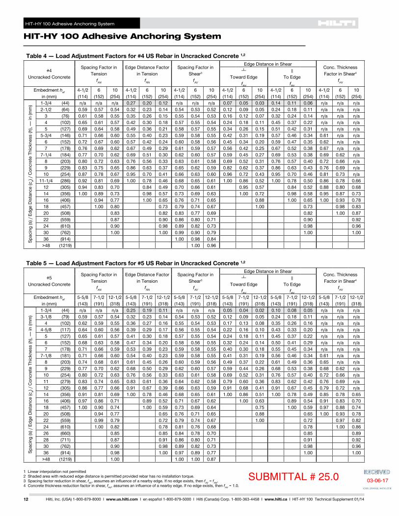
HIT-HY 100 Adhesive Anchoring System
HIT-HY 100 Adhesive Anchoring System
25Hilti Inc (USA) 1-800-879-8000 I wwwushilticom I en espantildeol 1-800-879-5000 I Hilti (Canada) Corp 1-800-363-4458 I wwwhiltica I HIT-HY 100 Technical Supplement 0114
Table 25 mdash Load Adjustment Factors for 78-in Diameter Fractional Threaded Rods in Uncracked Concrete 12
78 inUncracked Concrete
Spacing Factor in Tension
fAN
Edge Distance Factor in Tension
fRN
Spacing Factor in Shear3
fAV
Edge Distance in ShearConc Thickness Factor in Shear4
fHV
Toward Edge
fRV
To Edge
fRV
Embedment hef in (mm)
3-12 7-78 10-12 17-12 3-12 7-78 10-12 17-12 3-12 7-78 10-12 17-12 3-12 7-78 10-12 17-12 3-12 7-78 10-12 17-12 3-12 7-78 10-12 17-12(89) (200) (267) (445) (89) (200) (267) (445) (89) (200) (267) (445) (89) (200) (267) (445) (89) (200) (267) (445) (89) (200) (267) (445)
Spac
ing
(s)
Edg
e D
ista
nce
(ca)
Con
cret
e Th
ickn
ess
(h)
mdash in
(mm
)
1-34 (44) na na na na 036 023 017 010 na na na na 009 003 002 001 018 005 004 002 na na na na4-38 (111) 060 059 057 054 058 031 023 013 058 054 053 052 035 011 007 004 060 022 014 008 na na na na
5 (127) 062 061 058 055 061 033 024 014 059 054 053 052 043 013 009 005 066 027 017 010 na na na na5-12 (140) 063 062 059 055 065 034 025 015 060 055 054 052 050 015 010 006 072 031 020 011 065 na na na
6 (152) 064 063 060 056 068 036 026 016 061 055 054 053 057 017 011 006 078 035 023 013 068 na na na7 (178) 066 065 061 057 074 039 029 017 063 056 055 053 071 022 014 008 091 041 029 016 073 na na na8 (203) 069 067 063 058 081 043 032 018 065 057 055 054 087 027 017 010 100 044 035 020 078 na na na9 (229) 071 069 064 059 087 046 034 020 067 058 056 054 100 032 021 012 048 039 023 083 na na na
9-78 (251) 073 071 066 059 094 050 037 021 069 059 056 054 037 024 013 051 041 027 087 059 na na10 (254) 073 071 066 060 094 050 037 022 069 059 057 054 038 024 014 051 042 027 087 059 na na11 (279) 076 073 067 060 100 054 040 023 071 060 057 055 043 028 016 055 044 032 091 062 na na12 (305) 078 075 069 061 059 044 026 073 060 058 055 049 032 018 059 047 034 095 065 na na
12-12 (318) 079 076 070 062 062 045 027 074 061 058 056 052 034 019 062 048 035 097 066 057 na14 (356) 083 080 072 063 069 051 030 077 062 059 056 062 040 023 069 052 037 100 070 060 na16 (406) 087 084 075 065 079 058 034 080 064 060 057 076 049 028 079 058 040 075 065 na18 (457) 092 088 079 067 089 066 038 084 066 062 058 091 059 033 089 066 043 079 068 na
19-12 (495) 095 091 081 069 097 071 042 087 067 063 059 100 066 037 097 071 045 082 071 05920 (508) 097 092 082 069 099 073 043 088 067 063 059 069 039 099 073 046 083 072 06022 (559) 100 097 085 071 100 080 047 092 069 064 060 080 045 100 080 049 087 076 06224 (610) 100 088 073 087 051 096 071 066 061 091 051 087 052 091 079 06526 (660) 091 075 095 055 099 073 067 062 100 057 095 056 095 082 06828 (711) 094 077 100 060 100 074 068 062 064 100 060 099 085 07030 (762) 098 079 064 076 070 063 071 064 100 088 07336 (914) 100 084 077 081 073 066 094 077 097 080
gt48 (1219) 096 100 092 081 071 100 100 100 092
1 Linear interpolation not permitted2 Shaded area with reduced edge distance is permitted provided the installation torque is reduced to 030 Tmax for 5d le s le 16-in and to 05 Tmax for s gt 16-in3 Spacing factor reduction in shear fAV assumes an influence of a nearby edge If no edge exists then fAV = fAN4 Concrete thickness reduction factor in shear fHV assumes an influence of a nearby edge If no edge exists then fHV = 10
Table 26 mdash Load Adjustment Factors for 1-in Diameter Fractional Threaded Rods in Uncracked Concrete 12
1 inUncracked Concrete
Spacing Factor in Tension
fAN
Edge Distance Factor in Tension
fRN
Spacing Factor in Shear3
fAV
Edge Distance in ShearConc Thickness Factor in Shear4
fHV
Toward Edge
fRV
To Edge
fRV
Embedment hef in (mm)
4 9 12 20 4 9 12 20 4 9 12 20 4 9 12 20 4 9 12 20 4 9 12 20(102) (229) (305) (508) (102) (229) (305) (508) (102) (229) (305) (508) (102) (229) (305) (508) (102) (229) (305) (508) (102) (229) (305) (508)
Spac
ing
(s)
Edg
e D
ista
nce
(ca)
Con
cret
e Th
ickn
ess
(h)
mdash in
(mm
)
1-34 (44) na na na na 036 023 017 010 na na na na 008 002 001 001 015 005 003 002 na na na na5 (127) 061 059 057 054 059 031 023 013 059 054 053 052 037 011 007 004 061 022 014 008 na na na na6 (152) 063 061 058 055 064 034 025 015 060 055 053 052 048 014 009 005 070 029 019 011 na na na na
6-14 (159) 063 062 059 055 066 035 025 015 061 055 054 052 051 015 010 006 073 030 020 011 065 na na na7 (178) 065 063 060 056 070 037 027 016 062 055 054 053 061 018 012 007 082 036 023 013 069 na na na8 (203) 067 065 061 057 076 040 029 017 064 056 055 053 074 022 014 008 093 042 029 016 074 na na na9 (229) 069 067 063 058 082 043 032 019 065 057 055 054 089 026 017 010 100 045 034 019 078 na na na
10 (254) 071 069 064 058 088 046 034 020 067 058 056 054 100 031 020 011 048 040 023 083 na na na11 (279) 073 070 065 059 095 050 037 022 069 058 056 054 035 023 013 052 042 026 087 na na na
11-14 (286) 074 071 066 059 096 051 037 022 069 059 056 054 037 024 014 053 043 027 088 058 na na12 (305) 075 072 067 060 100 054 039 023 070 059 057 055 040 026 015 055 044 030 091 060 na na13 (330) 078 074 068 061 058 043 025 072 060 057 055 046 030 017 059 047 034 094 063 na na14 (356) 080 076 069 062 063 046 027 074 061 058 055 051 033 019 063 049 036 098 065 na na
14-14 (362) 080 076 070 062 064 047 027 074 061 058 056 052 034 019 064 050 036 099 066 057 na16 (406) 084 080 072 063 072 053 031 077 062 059 056 062 040 023 072 054 038 100 070 060 na18 (457) 088 083 075 065 080 059 035 081 064 060 057 074 048 028 080 059 041 074 064 na20 (508) 092 087 078 067 089 066 039 084 065 061 058 087 056 032 089 066 043 078 067 na22 (559) 097 091 081 068 098 072 042 088 067 063 059 100 065 037 098 072 046 082 071 na
22-14 (565) 097 091 081 069 099 073 043 088 067 063 059 066 038 099 073 046 082 071 05924 (610) 100 094 083 070 100 079 046 091 068 064 059 074 042 100 079 049 085 074 06126 (660) 098 086 072 086 050 094 070 065 060 084 048 086 052 089 077 06428 (711) 100 089 073 092 054 098 071 066 061 094 053 092 055 092 080 06630 (762) 092 075 099 058 100 073 067 062 100 059 099 058 095 083 06936 (914) 100 080 100 069 077 070 064 078 100 069 100 091 075
gt48 (1219) 090 093 086 077 069 100 093 100 087
SUBMITTAL 250
03-06-17
HIT-HY 100 Adhesive Anchoring System
HIT-HY 100 Adhesive Anchoring System
26 Hilti Inc (USA) 1-800-879-8000 I wwwushilticom I en espantildeol 1-800-879-5000 I Hilti (Canada) Corp 1-800-363-4458 I wwwhiltica I HIT-HY 100 Technical Supplement 0114
Table 27 mdash Load Adjustment Factors for 1-14-in Diameter Fractional Threaded Rods in Uncracked Concrete 12
1-14 inUncracked Concrete
Spacing Factor in Tension
fAN
Edge Distance Factor in Tension
fRN
Spacing Factor in Shear3
fAV
Edge Distance in ShearConc Thickness Factor in Shear4
fHV
Toward Edge
fRV
To Edge
fRV
Embedment hef in (mm)
5 11-14 15 25 5 11-14 15 25 5 11-14 15 25 5 11-14 15 25 5 11-14 15 25 5 11-14 11-14 25(127) (286) (381) (635) (127) (286) (381) (635) (127) (286) (381) (635) (127) (286) (381) (635) (127) (286) (381) (635) (127) (286) (286) (635)
Spac
ing
(s)
Edg
e D
ista
nce
(ca)
Con
cret
e Th
ickn
ess
(h)
mdash in
(mm
) 1-34 (44) na na na na 035 022 016 009 na na na na 005 002 001 001 011 003 002 001 na na na na6-14 (159) 062 059 057 054 062 032 023 014 059 054 053 052 037 011 007 004 063 022 015 009 na na na na
7 (178) 063 060 058 055 065 034 025 015 060 054 053 052 043 013 009 005 069 026 017 010 na na na na8 (203) 065 062 059 055 070 036 027 016 061 055 054 053 053 016 011 006 078 031 021 013 066 na na na9 (229) 067 063 060 056 075 039 029 017 062 055 054 053 063 019 013 008 087 038 025 015 070 na na na
10 (254) 069 065 061 057 081 042 031 018 064 056 055 053 074 022 015 009 097 044 029 018 074 na na na11 (279) 071 066 062 057 086 044 033 019 065 057 055 054 086 025 017 010 100 048 034 020 078 na na na12 (305) 072 068 063 058 092 047 035 020 066 057 056 054 098 029 019 012 051 039 023 081 na na na13 (330) 074 069 064 059 098 050 037 022 068 058 056 054 100 033 022 013 054 044 026 084 na na na14 (356) 076 071 066 059 100 054 040 023 069 059 057 055 036 024 015 056 046 029 087 058 na na
14-14 (362) 077 071 066 060 055 040 024 069 059 057 055 037 025 015 057 046 030 088 059 na na15 (381) 078 072 067 060 058 043 025 070 059 057 055 040 027 016 059 048 032 091 060 na na16 (406) 080 074 068 061 062 045 027 072 060 057 055 045 030 018 062 050 036 094 062 na na17 (432) 082 075 069 061 065 048 028 073 060 058 056 049 033 020 065 052 038 096 064 na na18 (457) 084 077 070 062 069 051 030 075 061 058 056 053 036 021 069 054 039 099 066 058 na20 (508) 087 080 072 063 077 057 033 077 062 059 057 062 042 025 077 058 041 100 070 061 na22 (559) 091 083 074 065 085 062 037 080 063 060 057 072 048 029 085 063 043 073 064 na24 (610) 095 086 077 066 092 068 040 083 065 061 058 082 055 033 092 068 046 076 067 na26 (660) 098 089 079 067 100 074 043 086 066 062 059 092 062 037 100 074 048 079 069 na28 (711) 100 091 081 069 079 047 088 067 063 059 100 069 041 079 050 082 072 06130 (762) 094 083 070 085 050 091 068 064 060 076 046 085 053 085 075 06336 (914) 100 090 074 100 060 099 072 067 062 100 060 100 060 094 082 069
gt48 (1219) 100 082 080 100 079 072 066 093 080 100 094 080
1 Linear interpolation not permitted2 Shaded area with reduced edge distance is permitted provided the installation torque is reduced to 030 Tmax for 5d le s le 16-in and to 05 Tmax for s gt 16-in3 Spacing factor reduction in shear fAV assumes an influence of a nearby edge If no edge exists then fAV = fAN4 Concrete thickness reduction factor in shear fHV assumes an influence of a nearby edge If no edge exists then fHV = 10
SUBMITTAL 250
03-06-17
HIT-HY 100 Adhesive Anchoring System
HIT-HY 100 Adhesive Anchoring System
27Hilti Inc (USA) 1-800-879-8000 I wwwushilticom I en espantildeol 1-800-879-5000 I Hilti (Canada) Corp 1-800-363-4458 I wwwhiltica I HIT-HY 100 Technical Supplement 0114
2410 Hilti HIT-HY 100 Adhesive with Hilti HIS-N and HIS-RN Internally Threaded Insert
Hilti HIS-N and HIS-RN Internally Threaded Insert Installation Conditions
Perm
issi
ble
Con
cret
e C
ondi
tions
UncrackedConcrete
DryConcrete
Perm
issi
ble
Dril
ling
Met
hod
Hammer Drilling with Carbide Tipped Drill Bit Water Saturated
Concrete
Mechanical PropertiesHilti HIS-N and HIS-RN Internally Threaded Insert Material Specifications fya Min futa
ksi (MPa) ksi (MPa)HIS-N Insert (38-in) 11MnPb30+C Carbon Steel conforming to DIN 10277-3 595 (410) 711 (490)HIS-N Insert (12-in to 34-in) 11MnPb30+C Carbon Steel conforming to DIN 10277-3 544 (375) 667 (460)HIS-RN Insert X5CrNiMo17122 K700 Stainless Steel conforming to DIN EN 10088-3 508 (350) 1015 (700)
Hilti HIS-N and HIS-RN Installation SpecificationsInternal Nominal
Rod Diameter
InsertExternal Diameter
DrillBit Diameter
Embedment Depth
BoltEmbedment
Maximum Installation
Torque
Minimum Base
Material Thickness
oslashdin (mm)
oslashDin (mm)
oslashd0in
hefin (mm)
hsin
Tmaxft-lb (Nm)
hminin (mm)
38 0651116
4-3838 ndash 1516
15 59(95) (165) (110) (20) (150)12 081
785
12 ndash 1-31630 67
(127) (205) (125) (41) (170)58 100
1-186-34
58 ndash 1-1260 91
(159) (254) (170) (81) (230)34 109
1-148-18
34 ndash 1-78100 106
(191) (276) (205) (136) (270)
min
maxSUBMITTAL 250 03-06-17
HIT-HY 100 Adhesive Anchoring System
HIT-HY 100 Adhesive Anchoring System
28 Hilti Inc (USA) 1-800-879-8000 I wwwushilticom I en espantildeol 1-800-879-5000 I Hilti (Canada) Corp 1-800-363-4458 I wwwhiltica I HIT-HY 100 Technical Supplement 0114
Table 28 mdash Hilti HIT-HY 100 Adhesive Design Strength (Factored Resistance) with Concrete Bond Failure for Hilti HIS-N and HIS-RN Internally Threaded Inserts in Uncracked Concrete 12345678
Anchor Diameter in (mm)
Effective Embedment
Depth in (mm)
Tension mdash ФNn or Nr Shear mdash ФVn or Vr
f´c = 2500 psi (172 Mpa)
lb (kN)
f´c = 3000 psi (207 Mpa)
lb (kN)
f´c = 4000 psi (276 Mpa)
lb (kN)
f´c = 6000 psi (414 Mpa)
lb (kN)
f´c = 2500 psi(172 Mpa)
lb (kN)
f´c = 3000 psi(207 Mpa)
lb (kN)
f´c = 4000 psi(276 Mpa)
lb (kN)
f´c = 6000 psi(414 Mpa)
lb (kN)38 4-38 7140 7820 8740 9265 15375 16840 18825 19955(95) (111) (318) (348) (389) (412) (684) (749) (837) (888)12 5 8720 9555 11030 12185 18785 20575 23760 26245
(127) (127) (388) (425) (491) (542) (836) (915) (1057) (1167)58 6-34 13680 14985 16265 17240 29460 32275 35030 37135
(159) (171) (609) (667) (723) (767) (1310) (1436) (1558) (1652)34 8-18 18065 19790 20165 21375 38910 42620 43430 46035
(191) (206) (804) (880) (897) (951) (1731) (1896) (1932) (2048)
1 See Section 24 for explanation on development of load values2 See Section 244 to convert design strength (factored resistance) value to ASD value3 Linear interpolation between embedment depths and concrete compressive strengths is not permitted4 Apply spacing edge distance and concrete thickness factors in table 30 as necessary Compare to the steel values in table 29
The lesser of the values is to be used for the design5 Data is for temperature range A Max short term temperature = 104deg F (40deg C) max long term temperature = 75deg F (24deg C)
For temperature range B Max short term temperature = 176deg F (80deg C) max long term temperature = 122deg F (50deg C) multiply above value by 075 For temperature range C Max short term temperature = 248deg F (120deg C) max long term temperature = 162deg F (72deg C) multiply above value by 041 Short term elevated concrete temperatures are those that occur over brief intervals eg as a result of diurnal cycling Long term concrete temperatures are roughly constant over significant periods of time
6 Tabular values are for dry concrete conditions For water saturated concrete multiply design strength (factored resistance) by 0857 Tabular values are for short term loads only For sustained loads including overhead use see Section 2458 Tabular values are for normal weight concrete only For lightweight concrete multiply design strength (factored resistance) by λa as follows
For sand-lightweight λa = 051 For all-lightweight λa = 045
Table 29 mdash Steel Design Strength (Factored Resistance) for Steel Bolt Cap Screw for Hilti HIS-N and HIS-RN Internally Threaded Inserts 56
InternalThread
Diameterin (mm)
ACI 318 Appendix D Based Design CSA A233 Annex D Based Design
ASTM A 193 B7ASTM A 193 Grade B8M
Stainless SteelASTM A 193 B7
ASTM A 193 Grade B8MStainless Steel
Tensile1
ϕNsa
lb (kN)
Shear2
ϕVsa
lb (kN)
Tensile1
ϕNsa
lb (kN)
Shear2
ϕVsa
lb (kN)
Tensile3
Nsr
lb (kN)
Shear4
Vsr
lb (kN)
Tensile3
Nsr
lb (kN)
Shear4
Vsr
lb (kN)38 6300 3490 5540 3070 5765 3215 5070 2825(95) (280) (155) (246) (137) (256) (143) (226) (126)12 11530 6385 10145 5620 10555 5880 9290 5175
(127) (513) (284) (451) (250) (470) (262) (413) (230)58 18365 10170 16160 8950 16810 9365 14790 8240
(159) (817) (452) (719) (398) (748) (417) (658) (367)34 27180 15055 23915 13245 24880 13860 21895 12195
(191) (1209) (670) (1064) (589) (1107) (617) (974) (542)
1 Tensile = ϕ AseN futa as noted in ACI 318 Appendix D2 Shear = ϕ 060 AseN futa as noted in ACI 318 Appendix D3 Tensile = Ase ϕs fut R as noted in CSA A233 Annex D2 Shear = Ase ϕs 060 fut R as noted in CSA A233 Annex D5 See Section 244 to convert design strength (factored resistance) value to ASD value6 Steel bolt cap screw for Hilti HIS-N and HIS-RN inserts are considered brittle steel elements
SUBMITTAL 250 03-06-17
HIT-HY 100 Adhesive Anchoring System
HIT-HY 100 Adhesive Anchoring System
29Hilti Inc (USA) 1-800-879-8000 I wwwushilticom I en espantildeol 1-800-879-5000 I Hilti (Canada) Corp 1-800-363-4458 I wwwhiltica I HIT-HY 100 Technical Supplement 0114
Table 30 mdash Load Adjustment Factors for Hilti HIS-N and HIS-RN Internally Threaded Inserts in Uncracked Concrete 1
HIS-N and HIS-RNAll DiametersUncracked Concrete
Spacing Factor in Tension
fAN
Edge Distance Factor in Tension
fRN
Spacing Factor in Shear2
fAV
Edge Distance in ShearConc Thickness Factor in Shear3
fHV
Toward Edge
fRV
To Edge
fRV
Internal Diameterin (mm)
38 12 58 34 38 12 58 34 38 12 58 34 38 12 58 34 38 12 58 34 38 12 58 34(95) (127) (159) (191) (95) (127) (159) (191) (95) (127) (159) (191) (95) (127) (159) (191) (95) (127) (159) (191) (95) (127) (159) (191)
Embedment hef in (mm)
4-38 5 6-34 8-18 4-38 5 6-34 8-18 4-38 5 6-34 8-18 4-38 5 6-34 8-18 4-38 5 6-34 8-18 4-38 5 6-34 8-18(111) (127) (171) (206) (111) (127) (171) (206) (111) (127) (171) (206) (111) (127) (171) (206) (111) (127) (171) (206) (111) (127) (171) (206)
Spac
ing
(s)
Edg
e Di
stan
ce (c
a) C
oncr
ete
Thic
knes
s (h
) mdash
in (m
m) 3-14 (83) 060 na na na 038 na na na 055 na na na 015 na na na 031 na na na na na na na
4 (102) 063 060 na na 043 041 na na 056 055 na na 021 019 na na 042 038 na na na na na na5 (127) 066 063 062 na 049 047 042 na 057 057 055 na 029 026 017 na 049 047 033 na na na na na
5-12 (140) 067 064 063 061 053 050 044 039 058 058 056 055 034 030 019 015 053 050 039 029 na na na na6 (152) 069 066 064 062 056 053 046 041 059 058 056 055 039 035 022 017 056 053 044 033 060 na na na7 (178) 072 068 066 064 064 059 051 045 060 060 057 056 049 043 028 021 064 059 051 042 064 062 na na8 (203) 075 071 068 066 074 066 056 049 062 061 058 057 060 053 034 026 074 066 056 050 069 066 na na9 (229) 078 074 071 068 083 075 061 053 063 062 059 058 071 063 040 031 083 075 061 054 073 070 na na
10 (254) 081 076 073 071 092 083 066 057 065 064 060 058 083 074 047 036 092 083 066 058 077 074 064 na11 (279) 084 079 075 073 100 091 072 061 066 065 061 059 096 086 055 041 100 091 072 062 081 078 067 06112 (305) 088 081 078 075 099 079 066 068 066 062 060 100 098 062 047 099 079 066 084 081 070 06414 (356) 094 087 082 079 100 092 077 071 069 064 062 100 078 059 100 092 077 091 087 075 06916 (406) 100 092 087 083 100 088 074 072 066 063 096 073 100 088 097 094 080 07318 (457) 097 091 087 099 077 075 068 065 100 087 099 100 099 085 07824 (610) 100 100 099 100 085 083 074 070 100 100 100 099 09030 (762) 100 094 091 080 075 100 10036 (914) 100 099 086 080
gt48 (1219) 100 099 090
1 Linear interpolation not permitted2 Spacing factor reduction in shear fAV assumes an influence of a nearby edge If no edge exists then fAV = fAN3 Concrete thickness reduction factor in shear fHV assumes an influence of a nearby edge If no edge exists then fHV = 10
SUBMITTAL 25003-06-17
HIT-HY 100 Adhesive Anchoring System
HIT-HY 100 Adhesive Anchoring System
30 Hilti Inc (USA) 1-800-879-8000 I wwwushilticom I en espantildeol 1-800-879-5000 I Hilti (Canada) Corp 1-800-363-4458 I wwwhiltica I HIT-HY 100 Technical Supplement 0114
2411 Installation InstructionsInstallation Instructions For Use (IFU) are included with each product package They can also be viewed or downloaded on-line at wwwushilticom (US) and wwwhiltica (Canada) mdash ldquoServiceTechnical Info gtgt Technical Downloads gtgt Anchoring Systemsrdquo Because of the possibility of changes always verify that downloaded IFU are current when used Proper installation is critical to achieve full performance Training is available on request Contact Hilti Technical Services for applications and conditions not addressed in the IFU
2412 Working Time and Cure Time
HIT-HY 100
HIT-V HASHIS-N
Rebar
[degC] [degF] twork tcure
-10-5 1422 3 h 12 h
-40 2331 40 min 4 h
15 3240 20 min 2 h
610 4150 8 min 60 min
1120 5168 5 min 30 min
2130 6986 3 min 30 min
3140 87104 2 min 30 min
Chemical Behavior
Acetic acid conc bull10 +
Acetone ndash
Ammonia conc bull5 +
Carbolic acid solution 10 ndashCarbon tetrachloride ndashChlorinated lime solution 10 +Citric acid 10 +Diesel oil bullEthanol ndash
Formic acid conc ndash10 bull
Gasoline Petrol bullGlycol +
Hydrochloric acid conc bull10 +
Hydrogen peroxide 10 +
Lactic acid conc +10 +
Machine oil bull
Nitric acid conc ndash10 bull
Phosphoric acid conc +10 +
Salt (common) solution 10 +Sea water +Soda solution 10 +
Sodium Hydroxide (Caustic soda)
40 bull20 +5 +
Sodium hypochlorite 2 +
Sulphuric acidconc ndash30 bull10 +
Toluene +Key ndash non-resistant + resistant bull limited resistance
Samples of the HIT-HY 100 resin were immersed in the various chemical compounds for up to one year At the time of the test period the samples were analyzed Any samples showing no visible damage and having less than a 25 reduction in bending (flexural) strength were classified as ldquoResistantrdquo Samples that had slight damage such as small cracks chips etc or reduction in bending strength of 25 or more were classified as ldquoPartially Resistantrdquo Samples that were heavily damaged or destroyed were classified as ldquoNot Resistantrdquo
Note In actual use the majority of the resin is encased in the base material leaving very little surface area exposed
2413 Resistance of Cured HIT-HY 100 to Chemicals
SUBMITTAL 250 03-06-17
Notes
31Hilti Inc (USA) 1-800-879-8000 I wwwushilticom I en espantildeol 1-800-879-5000 I Hilti (Canada) Corp 1-800-363-4458 I wwwhiltica I HIT-HY 100 Technical Supplement 0114
SUBMITTAL 250 03-06-17
Hilti Outperform OutlastPO Box 21148 Tulsa OK 74121 bull Hilti Inc (US) 1-800-879-8000 bull wwwushilticom bull en espantildeol 1-800-879-5000 bull Hilti (Canada) Corp 1-800-363-4458 wwwhiltica bull Hilti is an equal opportunity employer bull Hilti is a registered trademark of Hilti Corp copyCopyright 2014 by Hilti Inc (US) bull 0114 bull DBS
The data contained in this literature was current as of the date of publication Updates and changes may be made based on later testing If verification is needed that the data is still current please contact the Hilti Technical Support Specialists at 1-800-363-4458 All published load values contained in this literature represent the results of testing by Hilti or test organizations Local base materials were used Because of variations in materials on-site testing is necessary to determine performance at any specific site Laser beams represented by red lines in this publication Printed in the United States
14001 US only
SUBMITTAL 250 03-06-17
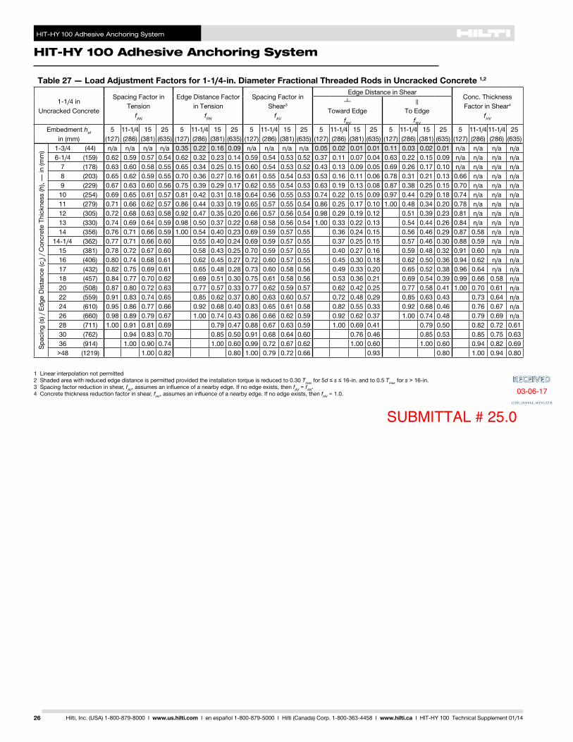
HIT-HY 100 Adhesive Anchoring System
HIT-HY 100 Adhesive Anchoring System
30 Hilti Inc (USA) 1-800-879-8000 I wwwushilticom I en espantildeol 1-800-879-5000 I Hilti (Canada) Corp 1-800-363-4458 I wwwhiltica I HIT-HY 100 Technical Supplement 0114
2411 Installation InstructionsInstallation Instructions For Use (IFU) are included with each product package They can also be viewed or downloaded on-line at wwwushilticom (US) and wwwhiltica (Canada) mdash ldquoServiceTechnical Info gtgt Technical Downloads gtgt Anchoring Systemsrdquo Because of the possibility of changes always verify that downloaded IFU are current when used Proper installation is critical to achieve full performance Training is available on request Contact Hilti Technical Services for applications and conditions not addressed in the IFU
2412 Working Time and Cure Time
HIT-HY 100
HIT-V HASHIS-N
Rebar
[degC] [degF] twork tcure
-10-5 1422 3 h 12 h
-40 2331 40 min 4 h
15 3240 20 min 2 h
610 4150 8 min 60 min
1120 5168 5 min 30 min
2130 6986 3 min 30 min
3140 87104 2 min 30 min
Chemical Behavior
Acetic acid conc bull10 +
Acetone ndash
Ammonia conc bull5 +
Carbolic acid solution 10 ndashCarbon tetrachloride ndashChlorinated lime solution 10 +Citric acid 10 +Diesel oil bullEthanol ndash
Formic acid conc ndash10 bull
Gasoline Petrol bullGlycol +
Hydrochloric acid conc bull10 +
Hydrogen peroxide 10 +
Lactic acid conc +10 +
Machine oil bull
Nitric acid conc ndash10 bull
Phosphoric acid conc +10 +
Salt (common) solution 10 +Sea water +Soda solution 10 +
Sodium Hydroxide (Caustic soda)
40 bull20 +5 +
Sodium hypochlorite 2 +
Sulphuric acidconc ndash30 bull10 +
Toluene +Key ndash non-resistant + resistant bull limited resistance
Samples of the HIT-HY 100 resin were immersed in the various chemical compounds for up to one year At the time of the test period the samples were analyzed Any samples showing no visible damage and having less than a 25 reduction in bending (flexural) strength were classified as ldquoResistantrdquo Samples that had slight damage such as small cracks chips etc or reduction in bending strength of 25 or more were classified as ldquoPartially Resistantrdquo Samples that were heavily damaged or destroyed were classified as ldquoNot Resistantrdquo
Note In actual use the majority of the resin is encased in the base material leaving very little surface area exposed
2413 Resistance of Cured HIT-HY 100 to Chemicals
SUBMITTAL 250 03-06-17
Notes
31Hilti Inc (USA) 1-800-879-8000 I wwwushilticom I en espantildeol 1-800-879-5000 I Hilti (Canada) Corp 1-800-363-4458 I wwwhiltica I HIT-HY 100 Technical Supplement 0114
SUBMITTAL 250 03-06-17
Hilti Outperform OutlastPO Box 21148 Tulsa OK 74121 bull Hilti Inc (US) 1-800-879-8000 bull wwwushilticom bull en espantildeol 1-800-879-5000 bull Hilti (Canada) Corp 1-800-363-4458 wwwhiltica bull Hilti is an equal opportunity employer bull Hilti is a registered trademark of Hilti Corp copyCopyright 2014 by Hilti Inc (US) bull 0114 bull DBS
The data contained in this literature was current as of the date of publication Updates and changes may be made based on later testing If verification is needed that the data is still current please contact the Hilti Technical Support Specialists at 1-800-363-4458 All published load values contained in this literature represent the results of testing by Hilti or test organizations Local base materials were used Because of variations in materials on-site testing is necessary to determine performance at any specific site Laser beams represented by red lines in this publication Printed in the United States
14001 US only
SUBMITTAL 250 03-06-17


![OCPS CLAY SPRINGS ES SUBMITTAL TRANSMITTAL...NALCO 2567 has complete freeze-thaw recovery; however, storage temperatures should be between 60 °F [15.6°C] and 120°F [48.9°C]. If](https://img.pdfslide.us/doc/110x75/60b6bcb2be17007f4c0700d1/ocps-clay-springs-es-submittal-transmittal-nalco-2567-has-complete-freeze-thaw.jpg)