Embed Size (px)
Citation preview

- 1 -
Subject : Using the TV meter for a satellite installation NASE786X-04-04
SEFRAM 7861 – 7862 – 7861HD – 7862HD field strength meters enable the configuration of a terrestrial or satellite TV reception
system. This application note is dedicated for people who use the field strength meter for the first time. This manual provides an
application to setup a TV satellite (DVB-S) reception system correctly with a universal LNB-equipped satellite dish.
1) Configuration
Operating the instrument step by step
- Plug the LNB cable into the appliance.
- Switch the field strength meter on by pressing the key and wait that the presentation screen appears (screen with the
product reference number and its serial number).
- Press the Parameter key : , the following window appears on the display.
BNC input
Meter front panel
Satellite dish
Antenna
Presentation screen
Sensitive wheel
Up/down and left/right keys
Sensitive keys
On / off
Direct access
function keys
Alphanumerical
keypad

- 2 -
Parameter windows Navigation
Sensitive keys
This window enables defining the field strength meter parameters to receive a satellite signal. In Europe, the most used satellites have already pre-recorded places(locations). As an example, this application has to allow the ASTRA 19.2°E satellite reception.
- Highlight the « Place » line with the up and down keys.
- Put the field strength meter on the 3rd place, named « ASTRA NUM »,with the right and left keys or with the sensitive wheel.
ASTRA NUM place
- Check that the field strength meter is in the same setup as in the previous example. This place contains enough programs of the
ASTRA 19.2°E satellite for this application (digital channels, horizontal/vertical polarity, high/low band).
- The « Thresholds » allow defining the limits for the level measurement. Their setups have already been installed but it is possible to
modify them (reserved to advanced users).
2) Adjust the satellite antenna
Now, you have to adjust the dish on the ASTRA 19.2°E satellite.
- First, switch the remote supply on (LNB supply). Press the « DiSEqC » key, the following window appears, go to the « Remote
supply » line with the up and down keys and choose ON in the menu with the sensitive keys. The « VDC » warning light in the front
panel flashes when the remote supply is switched on.
The menu for sensitive keys changes according to the line which is highlit. It enables modifying the selected parameter.
Table with programs
contained in the
place
Satellite frequency
band
Pre-loaded place
(satellite)
Highlit line
Menu for
sensitive
keys
Sensitive
wheel
Direction keys
Sensitives
keys

- 3 -
Remote supply
- Press twice the Spectrum key: to open the check sat mode.
- Choose the satellite to receive. Highlight the « Satellite » menu and press the direction keys or turn the sensitive wheel to choose « ASTRA1 19.2°E ». The field strength meter has to synchronise on the 4 satellite transponders so that the satellite dish is correctly
adjusted.
Check sat window
- Adjust the satellite dish until you hear the locking melody. This melody is audible as soon as a first transponder is locked. At the end of
the melody, beeps ring out. The more they are closer, the more the reception quality is good. Perfect the adjustment of the satellite dish
to obtain the best quality.
If the appliance is not synchronised on any transponder, the smiley is red.
If the appliance is synchronised and if the reception quality is average (<50%), it is orange.
If the appliance is synchronised and if the reception quality is good (>50%), it is green.
If the current consumption of the LNB is null (although the remote supply is activated), the head is not supplied and no
reception is possible. In this case, it is possible that the LNB is defective. Also check the cables and adapters that connect
the LNB to the field strength meter.
LNB supply current
- 4 -
4 synchronised transponders
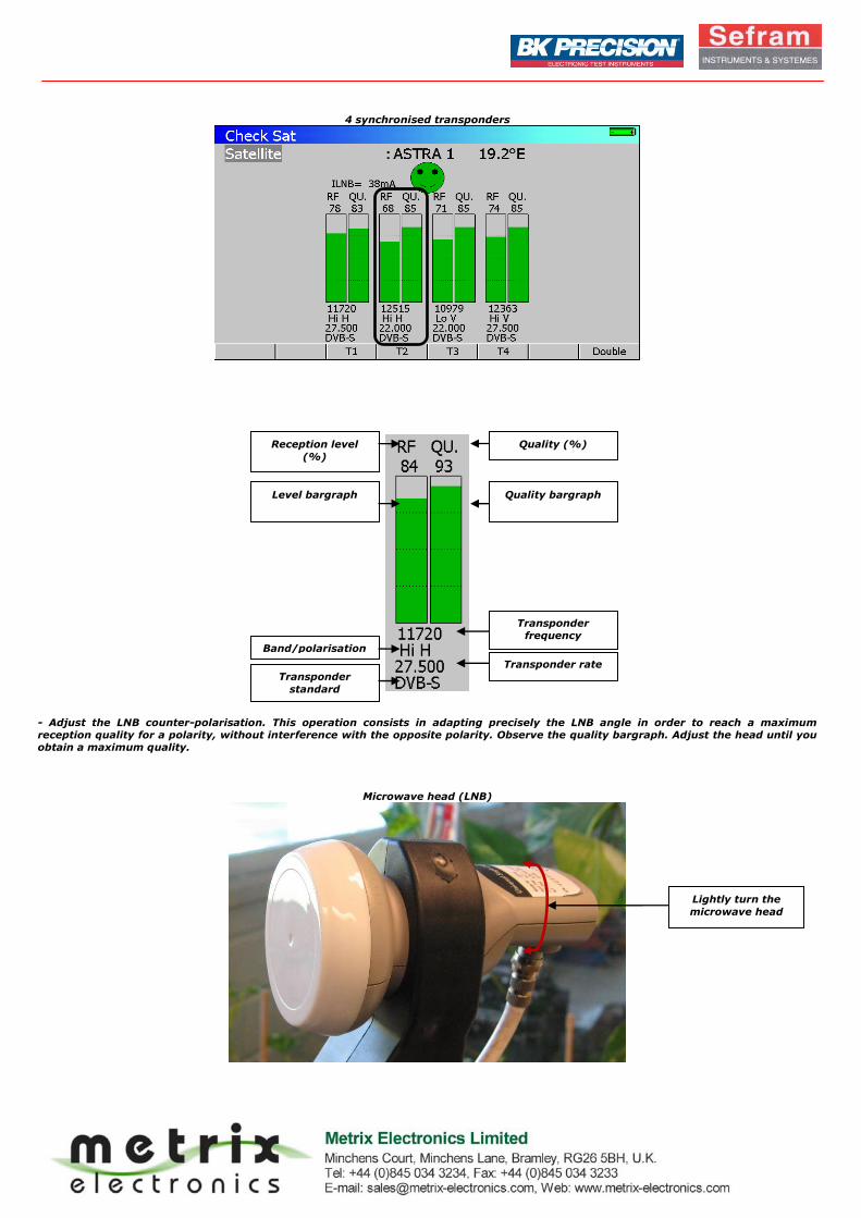
- Adjust the LNB counter-polarisation. This operation consists in adapting precisely the LNB angle in order to reach a maximum
reception quality for a polarity, without interference with the opposite polarity. Observe the quality bargraph. Adjust the head until you
obtain a maximum quality.
Microwave head (LNB)
Lightly turn the
microwave head
Reception level
(%)
Quality (%)
Quality bargraph
Transponder
frequency
Band/polarisation
nn Transponder rate
Transponder
standard
Level bargraph

- 5 -
Once the satellite adjusted, it is possible to see its spectrum.
- Press the Spectrum key : . The abscissa axis represents the frequencies and the ordinate axis the reception levels (in dBµV). The spectrum displayed depends on the selected band and polarity.
Band Low : 10 650MHz - 11 700MHz High : 11 700MHZ - 12 750MHz
Polarity Horizontal Vertical
Notes : - A transponder contains several.
- The transponder width changes : it can be 27MHz, 36MHz or 72MHz.
Spectrum analyser – High band – Vertical polarity
Inactive transponder
If a single transponder doesn’t synchronise (quality=0), it is possible that its frequency is not valid anymore (in satellite,
the used frequencies are regularly modified). Use the following sensitive keys to replace the non valid transponders by
active transponders.
The transponders of the different satellites are listed on websites that are regularly updated, like
http://en.kingofsat.net/. For the example with ASTRA 19.2°E : http://en.kingofsat.net/pos-19.2E.php.
Transponder
setting
Colour
Level : Red
Frequency : Blue
Band/Polarity
High band=Hi
Low band=Lo
Vertical polarity=V
Horizontal polarity=H
Carrier : this transponder
broadcasts TV
programs
Cursor that
indicates the position
Transponder menu
access
Saved
transponder

- 6 -
- As programs have already been saved in the ASTRA NUM place, it is possible to put the cursor directly on the corresponding carriers.
To do it, press the sensitive key «Setup», then change the transponder with the direction keys or the sensitive wheel. Here, the blue
cursor is put on the carrier that broadcasts « CNN INT. ».
- To identify the satellite from the spectrum :
Press the « Autoset » key : .Then, a MPEG2 NIT table search is operating on the transponder that is currently selected. The
automatic recognition of the satellite is made in many steps :
- digital transponder search around the cursor position ;
- digital decoder locking ; - MPEG NIT table reception waiting ;
- display : satellite name, orbital position, Network name and Network ID.
These instructions can take a few minutes. Once this process is finished, the following window appears in the middle of the spectrum:
Satellite identification
Some broadcasters don’t give information ( or badly) to the MPEG2 NIT table. The informations displayed at the acquisition end can be
erroneous. The following error messages can also appear.
- Impossibility locking on the transponder :
- Satellite identification failed : no NIT or wrong information, unlocking :
3) Measurements
- Press the « Measurements » key :
A new window appears on the display «Signal level». The first measures displayed correspond to the program previously selected on
the spectrum (here CNN INT). By selecting the « Setup # » line, then turning the sensitive wheel, it is possible to recall the other saved programs( in the ASTRA NUM place) to operate the measurements.
Signal level window
- If necessary, check the transponder characteristics (frequency, band, polarity, standard, symbol rate ) on the website
http://en.kingofsat.net/satellites.php.
Example : transponder broadcasting CNN INT.
Astra 1M (19.2E) - 11778.00 V - Txp: 68 - Beam: Astra 1M DVB-S (QPSK) - 27500 3/4 - NID:1 - TID:1068
Signal level
measure
Signal/noise ratio
measure
Transponder
characteristics
Transponder
frequency
Polarity Symbol rate Transponder
standard
Mini-spectrum
that represents
the transponder
Orbital position Satellite name
Network name Network ID

- 7 -
- Analyse the measures :
Signal level
- V : represents the received signal level - VLNB : LNB supply voltage
(13V =vertical polarisation and 18 V = horizontal polarisation)
- C/N : means carrier/noise ratio - ILNB : LNB supply current
Thanks to different colours, a threshold system enables seeing the signal quality easily. On the display digital values and bargraphs
appear.
The thresholds are set up according to reference values. For an digital signal, the transponder measures have to correspond to the next
data.
For a digital signal, the V and C/N measures don’t guarantee the signal quality by themselves. It is imperative to measure the error
rates (BER/MER) to fully characterise the reception quality.
Error rates
To operate the error rate measurements :
Press for the second time the « Measurements » key:
A new window appears on the display : « DVB-S : BER/MER ».
DVB-S : BER/MER window
- Analyse the measures :
The BER (Bit Error Ratio) et MER (Modulation Error Ratio) measures are very important to qualify a DVB-S digital signal.
- CBER : error rate before the Viterbi correction ;
- VBER : error rate after the Viterbi correction ;
- UNC : lost packet number after the Reed Salomon decoder ;
- MER : modulation error rate ( generally equivalent to the C/N measure).
The bargraphs appears in colour according to the measures error :
Signal level at the antenna plug
47dBμV < V < 77dBμV
Signal / noise ratio
DVB-S standard : C/N > 11dB
Transponder
characteristics
Error ratio
measure
VBER > à 2E-4
(QEF : quasi error free)
Without lost packets
Lost packets (UNC) Correct error rate
Minimum
threshold
Maximum
threshold

- 8 -
For an installation of quality, follow the next reference values. Check that the measurements operated on the transponder correspond to
them.
Error ratios
Measures
BER ME
R
(
d
B
)
DVB-S VBER <
2E-4
>
1
1
4) TV display
Caution : if you rely only on the picture, without taking the measures into account, you won’t have a correct system adjustment.
Press the key to display the transponder that corresponds to current measures.
If, in TV mode, the screen remains black but the NIT appears in the top right-hand corner of the screen, it means that the transponder
is well synchronised. Nevertheless, a subscription is necessary to see this not free TV program. The term « Conditional access »
indicates that the program can’t appear.
NIT – Conditional access
A transponder contains many TV programs. To access to a channel that is broadcasting in clear on the transponder, press the sensitive
key« Serv ». This button enables selecting the TV program to see. Choose a TV program with the direction keys and validate it with the
green validation key in the sensitive menu.
TV program choice TV window
Different application notes can be downloaded on our website ; they allow understanding more in details some functions of the field
strength meters (http://www.sefram.com/wwwFR/F_download.asp).
Product link : http://www.sefram.com/wwwFR/F_quick_search.asp?st=7861
The sign « < » before an error ratio value shows that there has not been any error (for example « <1E-8 » indicates an
error rate less than 1E-8).
Transponder change
(among those that are
saved in the place)
Program change
(in the current
transponder)
Transponder
NIT