Embed Size (px)
Citation preview
Studying Different Types of Power Converters
Fed Switched Reluctance Motor
Samia M. Mahmoud, Mohsen Z. El-Sherif, and Emad S. Abdel-Aliem
Shoubra Faculty of Engineering, Cairo, Egypt
Email: [email protected], [email protected]
Maged N. F. Nashed
Electronics Research Institute, Cairo, Egypt
Email: [email protected]
Abstract—This paper presents requirements, detailed
analysis, and operation of six converter types used with 3-
phase 6/4 switched reluctance motor (SRM). These
converters are R-dump, C-dump, C-dump with
freewheeling transistor, asymmetric, series, and parallel
type. The simulation results are made by
MATLAB/SIMULINK package. The paper also introduced
why the asymmetric bridge converter type is the best one
especially for high speeds.
Index Terms—SRM, R-dump, C-dump, C-dump with
freewheeling, asymmetric, series, parallel converter
I. INTRODUCTION
The operation of SRM is quite simple because of its
ability to operate efficiently from unidirectional winding
currents, thus only one switch per phase is sufficient
yielding a very economical brushless drive but in ac
motor drives at least two switches per phase are required.
Furthermore, a phase winding in series with a switch in
the SRM but the windings are not in series with switches
in ac drives that lead to irreparable damage in shoot-
through faults. In the case of a shoot-through fault, the
phase inductance limits the rate of rise in current and
provides time to initiate protective relaying to isolate the
faults. The SRM phases are independent and, in the case
of one winding failure, uninterrupted operation of the
motor drive operation is still possible although with
reduced power output [1]. The drive system for 3-ph 6/4
SRM with H-bridge converter is shown in Fig. 1.
The power converter is a power supply unit that
follows the commands of the controller to energize each
phase of the motor at the appropriate times. It is required
to activate and commutate the motor phases. Therefore, it
does not only deliver energy to an electronic device from
an electrical outlet, it also regulates the current to meet
specific device requirements and should have the ability
of regulation to provide increasing or decreasing of phase
current. The position detector detects the rotor position
because phase excitation pulses need to be properly
synchronized to the rising region of the inductance profile
Manuscript received June 19, 2013, revised December 1, 2013.
for motoring operation. The controller regulates the
motor performance. It has to posses the rotor position
signal. It may be realized by a rotor position sensor or a
sensorless control procedure, e.g. from analyzing induced
voltages in the phase windings [2]-[4].
Figure 1. Basic configuration of 3-ph 6/4 SRM drive system.
The optimum performance of SRM depends upon the
appropriate positioning of the currents relative to rotor
position. At controlling the motor; as the current passes
through one phase, the torque is generated by the
tendency of the rotor to align with the excited stator pole.
The direction of the torque generated is a function of the
rotor position with respect to the energized phase, and is
independent of the direction of current flowing through
the phase winding. Continuous torque can be produced by
synchronizing each phase’s excitation with the rotor
position. The amount of current flowing through motor
windings is controlled by switching on and off by the
power electronic switches.
The power converter is the heart of the motor drive.
The performance, size, and the cost of the motor drive are
mainly depends upon the selected converter type of the
power converter circuit. So, this paper introduces a
comparison between different converter types used with
3-ph 6/4 SRM. The motor parameters are presented in
Appendix A.
281
International Journal of Electronics and Electrical Engineering Vol. 1, No. 4, December, 2013
©2013 Engineering and Technology Publishingdoi: 10.12720/ijeee.1.4.281-290

II. REQUIREMENTS OF SRM CONVERTER
The selection of converter topology for a certain
application is an important issue. Basically, the SRM
converter has some requirements [5], such as:
Each phase of motor has at least one switch to be
able to conduct independently.
The converter should be able to excite the phase
before it enters the generating or demagnetizing
region.
In order to improve converter performance; such as
higher efficiency, faster excitation time, fast
demagnetization time, high power, and fault tolerance. So,
the converter must satisfy some additional requirements
[3], [6]-[8]:
The converter energy can be supplied to one phase
while extracting it simultaneously from the other
phase. So, the converter should be able to allow
phase overlap control.
For the phase current control; it is necessary to
modulate the phase voltage using Pulse Width
Modulation (PWM) technique at low speeds.
Sufficiently high forcing voltage at each operation
point so that the current is injected sufficiently
quickly into the winding at high speed. The
required control method may be single pulse or
hysteresis current control. By this control; the
demagnetization time is reduced for avoiding
negative torque and / or permitting an extension of
commutation period (i.e.; dwell angle).
The demagnetization energy from the outgoing
phase should be fed back to the dc source (dc-link
capacitor) or using it in the incoming phase.
The converter should be able freewheel during the
chopping period to reduce the switching frequency.
So the switching loss and hysteresis loss may be
reduced.
The converter has to be single rail of power source
in order to reduce the voltage stress across the
semiconductor switches.
The converter should not require bifilar windings
or rely upon the motor construction.
The converter should have resonant circuit to
apply zero-voltage or zero-current switching for
reducing switching loss.
A low number of semiconductor switches is
desirable.
Apply power factor correction circuit in order to
improve the power factor.
Little complexity of converter is required.
Selecting the proper switching strategy, dwell angle
and control technique (usually hysteresis current control)
will define the efficiency and application of this converter.
III. TYPES OF SRM CONVERTERS
The converter fed SRM is powered from fixed voltage
dc-link, which is established by an ac/dc converter or
directly by a battery bank. The selection of suited
converter and control scheme depends on the
performance and the requirements of the specified SRM
application [3], [9]. The SRM features of operation must
be pointed out before determining the converter types
used. These features can be summarized in three tasks [5]:
The current must be supplied into the phase only
in the positive gradient period of its inductance
profile.
The torque should be maximized during phase
energizing of the motor phase. This is achieved by
shaping the phase current by maximize its amount
at rise time period and minimize it at fall time
period.
The stored magnetic energy during the
commutation period should be freewheeled or
returned to the dc source.
A. R-Dump Converter
The R-dump converter type is shown in Fig. 2. It is one
of the configurations which have one switch (i.e.,
transistor) and one diode per phase. The value of
resistance R determines the power dissipation and also
the switch voltage. The change in the value of R should
be done to achieve both reasonable stress on the switch
(increases with higher R), and appropriate fall time of the
current (increases with lower R). When the switch T1 is
turned off, the current freewheels through diode D1,
charging Cs, and later flows through the external resistor
R. This resistor partially dissipates the energy stored in
the energized phase [10], [11].
Figure 2. R-dump converter.
The design considerations such as the turn-off transient
voltage have to be included in rating of the switch T1. If
the current comes under the negative slope region of the
phase inductance, negative torque will be generated,
decreasing the average motoring torque. This converter
has the disadvantage that the current in any of phases will
take longer to extinguish compared to recharging the
source and also the energy is dissipated in a resistor; thus
reducing the overall efficiency of the motor drive [10].
B. C-Dump Converter
This converter type is considered as a converter of
auxiliary voltage supply [1]; because the demagnetization
energy of a phase is fed into an auxiliary voltage supply
which is a dump capacitor in order to restore the
intermediate circuit or for directly energizing the
282
International Journal of Electronics and Electrical Engineering Vol. 1, No. 4, December, 2013
©2013 Engineering and Technology Publishing
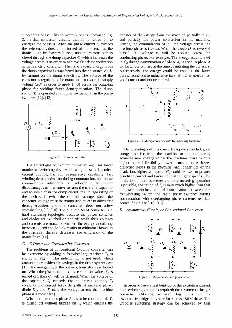
succeeding phase. This converter circuit is shown in Fig.
3. In that converter, assume that T1 is turned on to
energize the phase a. When the phase current ia exceeds
the reference value, T1 is turned off, this enables the
diode D1 to be forward biased, and the current path is
closed through the dump capacitor Cd which increases the
voltage across it in order to achieve fast demagnetization
as asymmetric converter. Then the excess energy from
the dump capacitor is transferred into the dc source via Lr
by turning on the dump switch Tr. The voltage of the
capacitor is regulated to be maintained at twice the supply
voltage (2U) in order to apply (−U) across the outgoing
phase for yielding faster demagnetization. The dump
switch Tr is operated at a higher frequency than the phase
switches [12], [13].
Figure 3. C-dump converter.
The advantages of C-dump converter are; uses lower
number of switching devices allowing phase independent
current control, has full regenerative capability, fast
winding demagnetization during commutation, and phase
commutation advancing is allowed. The major
disadvantages of that converter are; the use of a capacitor
and an inductor in the dump circuit, the voltage rating of
the devices is twice the dc link voltage, since the
capacitor voltage must be maintained at 2U to allow fast
demagnetization, and the converter does not allow
freewheeling [1], [10]. The C-dump SRM converters are
hard switching topologies because the power switches
and diodes are switched on and off while their voltages
and currents are nonzero. Further, the energy circulating
between Cd and the dc link results in additional losses in
the machine, thereby decreases the efficiency of the
motor drive [14].
C. C-Dump with Freewheeling Converter
The problems of conventional C-dump converter can
be overcome by adding a freewheeling transistor Tf as
shown in Fig. 4. The inductor Lr is not used, which
amounts to considerable savings in the drive system cost
[16]. For energizing of the phase a; transistor T1 is turned
on. When the phase current ia exceeds a set value, T1 is
turned off, then Cd will be charged. When the voltage of
the capacitor Cd exceeds the dc source voltage, Tf
conducts and current takes the path of machine phase,
diode D1, and Tf (see, the voltage across the machine
phase is almost zero).
When the current in phase A has to be commutated, T1
is turned off without turning on Tf which enables the
transfer of the energy from the machine partially to Cd
and partially for power conversion in the machine.
During the commutation of T1, the voltage across the
machine phase is (U−vo). When the diode Ds is reversed
biased; the voltage vo will be applied across the
conducting phase. For example, The energy accumulated
in Cd during commutation of phase a, is used in phase b
for faster current rise at the time of initiating the current ib.
Alternatively, the energy could be used in the latter
during rising phase inductance (say, at higher speeds) for
good current and torque control.
Figure 4. C-dump converter with freewheeling transistor.
The advantages of this converter topology includes; no
energy transfer from the machine to the dc source,
achieves zero voltage across the machine phase to give
higher control flexibility, lower acoustic noise, lower
dielectric losses in the machine, and longer life of the
insulation, higher voltage of Cd could be used to greater
benefit in current and torque control at higher speeds. The
limitations in this converter are; only motoring operation
is possible, the rating of Tf is very much higher than that
of phase switches, control coordination between the
freewheeling switch and main phase switches during
commutation with overlapping phase currents restricts
control flexibility [10], [15].
D. Asymmetric, Classic, or Conventional Converter
Figure 5. Asymmetric bridge converter.
In order to have a fast built-up of the excitation current,
high switching voltage is required; the asymmetric bridge
converter (H-bridge) is used. Fig. 5, shows the
asymmetric bridge converter for 3-phase SRM drive. The
unipolar switching strategy can be achieved by that
283
International Journal of Electronics and Electrical Engineering Vol. 1, No. 4, December, 2013
©2013 Engineering and Technology Publishing

converter which consists of two power switches and two
diodes per phase. In each phase, the upper switch is used
to perform the PWM switching control, while the lower
one is used in charge of commutation. Each phase can be
controlled independently. The three current modes of
operation, defined as magnetization, freewheeling, and
demagnetization mode [3]. The benefit of using unipolar
switching strategy is to obtain less current ripple and a
better frequency response in the inner current control
loop of the drive system [17], [18].
With the asymmetric converter, the SRM is usually
controlled by either current control or voltage control.
The main advantage of current control over voltage
control is that the phase current can be controlled
precisely, which means that torque is properly controlled
and the reduction of torque ripple or noise is possible. In
the SRM drive system, the current reference value is
enforced with a current feedback loop where it is
compared with the phase current. The current error is
presumed to be processed through a hysteresis controller
with a current window of the value (Δi). When the current
error exceeds the value (–Δi), the phase switches are
turned off simultaneously. At that time the phase diodes
complete the path through the dc source [19], [20]. The advantages of a classic converter are; allows
greater flexibility in controlling the machine current
because the converter is capable of applying the values of
supply voltages (U, –U, and 0), all the phases can be
controlled independently which is very essential for very
high speed operation, so, if one switch is damaged, the
drive can still with reduced power level, provides the
maximum control flexibility, fault tolerance capability,
the voltage stresses across the switching element is
restricted to supply voltage value, and also the least noise
is produced [1], [10], [21]. The disadvantages are; one
switch is always in the current conduction path, thus
increasing the losses in the converter and requiring a
larger heat sink for cooling. This would further reduce the
system efficiency. Two devices are always in series with
the motor winding, which increases the conduction loss,
size of the drive as well as cost increases because three
switches and three diodes are used for 3-ph SRM drive.
This converter produces a relatively low demagnetizing
voltage at high speeds [10], [19], [22], [23]. Through complete the reading of that paper, it is found
that the asymmetric converter topology is suitable for
high speed operation due to the fast fall and rise times of
current and also provide negligible shoot through faults.
In the asymmetric bridge converter; there is no presence
of high heat or copper losses because the absence of the
resistance commutation circuit or any coil added to the
converter topology. So, it is considered as the most
suitable converter for high power SRM drives [19], [24].
E. Series Passive Converter
As mentioned in [3], [25], [26]; the passive converter
of series capacitor is modified from the classical bridge
converter by adding one diode and one boosting capacitor
in series with the phase windings as shown in Fig. 6; to
achieve voltage boosting capability. In this circuit, the
boosting capacitor is charged resonantly by the use of
motor phase windings during the phase turn off periods.
The maximum boost voltage can be obtained by a
suitable size of the capacitor. Because the discharge of
the boost capacitor is not controllable in the passive
converter, the voltage of the boost capacitor is changed
by the stored magnetic energy during different operating
condition. When the phase switch is turned on, the
voltage of the boost capacitor may fall very fast until the
voltage reaches the dc link voltage (+U).
Figure 6. Series converter.
To handle the charging of the boosting capacitor (Cb)
in the beginning of the conduction period, one diode is
needed to series or parallel with the power switch to
protect the power switch [3]. After charging of the
capacitor (Cb), there are three modes of operation; in the
magnetization mode, T1 and T2 are turned on, the
charging across the capacitor (Cb) is discharged and
decreased down to zero, the voltage (+U) is applied to the
phase winding, then, the phase-A winding is energized
with the current flow through the path of U, Da, T1, L1, T2,
and U. In the freewheeling mode where the winding
voltage is zero; if the current in the winding exceeds the
reference value, either T1 or T2 is turned off, the current
that is flowing in the winding is free-wheeling through
one path, either the path of L1, T2, D2 or the path of L1, D1,
and T1. In the demagnetization mode, the stored magnetic
energy of the energized winding also charges the
incoming phase winding. Also, that the stored magnetic
energy may use to charge the two capacitors (Cb & Cf) in
series, so, a part of the energy is stored in the boost
capacitor to build up a boost voltage [3], [8].
F. Parallel passive converter
As mentioned in [3], [25], [26]; the passive converter
of parallel capacitor is modified from the classical bridge
converter by adding one boosting capacitor in parallel
with the phase windings to achieve voltage boosting
capability. The parallel type converter for 3-ph SRM is
shown in Fig. 7. Due to the direction of diode (Da), the
stored magnetic energy is only feed back to the boost
capacitor (Cb). The maximum boost voltage can be
obtained by a suitable size of the capacitor. Because the
discharge of the boost capacitor is not controllable in the
passive converter, the voltage of the boost capacitor is
changed by the stored magnetic energy during different
operating condition. When the phase switch is turned on,
284
International Journal of Electronics and Electrical Engineering Vol. 1, No. 4, December, 2013
©2013 Engineering and Technology Publishing

the voltage of the boost capacitor may fall very fast until
the voltage reaches the dc link voltage (+U). The boost
capacitor as in [8] increases the turn-on and turn-off
voltage applied to the motor phases for motoring action.
All the semiconductor devices except (Da) must be rated
for the boost voltage plus transients [27].
After charging of the capacitor (Cb) through the diode
(Da), there are three modes of operation; in the
magnetization mode, T1 and T2 are turned on, the
charging across the capacitor (Cb) is discharged and
decreased down to zero, the voltage (+U) is applied to the
phase winding, then, the phase-A winding is energized
with the current flow through the path of U, Da, T1, L1, T2,
and U. In the freewheeling mode where the winding
voltage is zero; if the current in the winding exceeds the
reference value, either T1 or T2 is turned off, the current
that is flowing in the winding is free-wheeling through
one path, either the path of L1, T2, and D2 or the path of L1,
D1, and T1. In the demagnetization mode, the stored
magnetic energy of the energized winding also charges
the incoming phase winding. Also, that the stored
magnetic energy may use to charge the boost capacitors,
so, a part of the energy is stored in the boost capacitor to
build up a boost voltage [3], [8].
Figure 7. Series converter.
TABLE I. COMPARISON BETWEEN THE SIX POWER CONVERTERS
Features R-dump C-dump & C-dump with freewheeling
Asymmetric,
Series &
Parallel
Phase Independence complete partial complete
Freewheeling allowed allowed allowed
No. of devices low (N) low (N+1) high (2N)
Performance fair very good very good
Control simple complex simple
Efficiency low high high
Torque per ampere low high medium
Fault tolerance low low high
A comparison of the above discussed topologies used
for 3-ph 6/4 SRM is summarized in Table I. The selection
of a converter, in most of the cases, depends upon the
application. For low performance applications where
precise control of torque is not required, low cost
converters can be employed. For applications, which
require precise and simple control and where efficiency
and reliability are important, a high performance
converter which can provide fast demagnetization of
phases is required.
IV. SIMULINK MODELS AND SIMULATION RESULTS
FOR SRM CONVERTERS
A. Results for R-Dump Converter
The complete model using R-dump converter is shown
in Fig. 8. The inductances, currents, total torque, and
motor speed are shown in Fig. 9. Where; La, Ia are solid
lines & Lb, Ib are dashed lines & Lc, Ic are dotted lines.
The system reachs its steady speed at angle 3 rad.. During
steady state operation, the maximum phase current is
2.435 A, the average phase current is 1.231 A, and the
average total torque developed by motor is 1.797 Nm at
940 rpm. The evolution of energy conversion for
calculating the work done and motor average torque can
be represented for phase a by Fig. 10.
Figure 8. Simulink model of 3-ph 6/4 SRM using R-dump converter
0 1 2 3 4 5 6 7 8 9 100
0.5
1
(
a)
La &
Lb &
Lc (
H)
0 1 2 3 4 5 6 7 8 9 100
2
4
6
(b)
I a &
Ib &
Ic (
A)
0 1 2 3 4 5 6 7 8 9 100
5
10
(c)
Te (
Nm
)
0 1 2 3 4 5 6 7 8 9 100
500
1000
Rotor Position (rad)
(d)
W (
rp
m)
Lc
La
Lb
Ic
Ia
Ib
Figure 9. Simulation results versus rotor position for R-dump:
(a)Inductances (b)Currents (c)Total torque (d)Speed
285
International Journal of Electronics and Electrical Engineering Vol. 1, No. 4, December, 2013
©2013 Engineering and Technology Publishing

0 0.5 1 1.5 2 2.5 3 3.5 4 4.5 50
0.5
1
1.5
2
2.5
Instantaneous phase current (A)
Inst
an
tan
eo
us
ph
ase
flu
x (
Wb
)
Figure 10. Evolution of energy conversion at using R-dump converter
B. Results for C-Dump Converter
The simulation model using C-dump converter is
shown in Fig. 11. The simulink results are shown in Fig.
12. The system reachs its steady speed at a step angle
about 3 rad. The simulation results during steady state
shows that the shape of phase inductance is not distorted.
During steady state operation, the maximum phase
current is 2.443 A, the average phase current is 0.9053 A,
and the average total torque developed by motor is 1.759
Nm at 927 rpm. The evolution of energy conversion for
calculating the work done and motor average torque can
be represented for phase a by Fig. 13.
Figure 11. Simulink model of 3-ph 6/4 SRM using C-dump converter
0 1 2 3 4 5 6 7 8 9 100
0.5
1
(a
)L
a &
Lb &
Lc (
H)
0 1 2 3 4 5 6 7 8 9 100
2
4
6
(
b)
Ia &
Ib &
Ic (
A)
0 1 2 3 4 5 6 7 8 9 100
5
10
(c)
Te (
Nm
)
0 1 2 3 4 5 6 7 8 9 100
500
1000
Rotor Position (rad)
(d
)
W (
rp
m)
Lc
La
Lb
Ic
Ia
Ib
Figure 12. Simulation results versus rotor position for C-dump: (a)inductances (b)currents (c)total torque (d)speed
0 0.5 1 1.5 2 2.5 3 3.5 4 4.5 50
0.5
1
1.5
2
2.5
Instantaneous phase current (A)
Inst
anta
neous
phase
flu
x l
inkage (
Wb)
Figure 13. Evolution of energy conversion at using C-dump converter
C. Results for C-Dump with Freewheeling Converter
The complete simulation model using the C-dump
converter with freewheeling transistor is shown in Fig. 14.
The simulink results of phases inductance, phases current,
total torque, and motor speed are shown in Fig. 15. The
system reachs its steady speed at a step angle about 6 rad.
The simulation results during steady state shows that the
shape of phase inductance is not distorted. During steady
state operation, the maximum phase current is 2.724 A,
the average phase current is 1.028 A, and the average
total torque is 2.099 Nm at 1090 rpm. The evolution of
energy conversion for phase a; is shown in Fig. 16.
Figure 14. Simulink model of 3-ph 6/4 SRM using C-dump converter type with freewheeling transistor
0 1 2 3 4 5 6 7 8 9 100
0.5
1
(a)
La &
Lb &
Lc (
H)
0 1 2 3 4 5 6 7 8 9 100
2
4
6
(
b)
Ia &
Ib &
Ic (
A)
0 1 2 3 4 5 6 7 8 9 100
5
10
(c)
Te (
Nm
)
0 1 2 3 4 5 6 7 8 9 100
500
1000
Rotor Position (rad)
(d
)
W (
rp
m)
Lc
La
Lb
Ic
Ia
Ib
Figure 15. Simulation results versus rotor position for C-dump with freewheeling transistor: (a)Inductances (b)Currents (c)Total torque
(d)Speed
286
International Journal of Electronics and Electrical Engineering Vol. 1, No. 4, December, 2013
©2013 Engineering and Technology Publishing

0 0.5 1 1.5 2 2.5 3 3.5 4 4.5 50
0.5
1
1.5
2
2.5
Instantaneous phase current (A)
In
stan
tan
eo
us p
hase f
lu
x l
in
kag
e (
Wb
)
Figure 16. Evolution of energy conversion at using C-dump converter with freewheeling transistor
D. Results for Asymmetric Bridge Converter
The complete simulation model using the asymmetric
bridge (H-bridge) converter is shown in Fig. 17. The
simulink results of phases inductance, phases current,
total torque, and motor speed are shown in Fig. 18. The
system reachs its steady speed at a step angle about 5 rad.
The simulation results during steady state shows that the
shape of phase inductance is not distorted. During steady
state operation, the maximum phase current is 2.379 A,
the average phase current is 0.953 A, and the average
total torque developed by motor is 1.756 Nm at 946 rpm.
The evolution of energy conversion for phase a is shown
in Fig. 19.
Figure 17. Simulink model of 3-ph 6/4 SRM using H-bridge converter
0 1 2 3 4 5 6 7 8 9 100
0.5
1
(a)
La &
L
b &
L
c (H
)
0 1 2 3 4 5 6 7 8 9 100
2
4
6
(b
)
Ia &
I
b &
I
c (A
)
0 1 2 3 4 5 6 7 8 9 100
5
10
(c)
Te (N
m)
0 1 2 3 4 5 6 7 8 9 100
500
1000
Rotor Position (rad)
(d
)
W (rp
m)
Lc
La
Lb
Ic
Ia
Ib
Figure 18. Simulation results versus rotor position for H-bridge converter: (a)Inductances (b)Currents (c)Total torque (d)Speed
0 0.5 1 1.5 2 2.5 3 3.5 4 4.5 50
0.5
1
1.5
2
2.5
Instantaneous phase current (A)
Instantaneous p
hase f
lux l
inkage (
Wb)
Figure 19. Evolution of energy conversion at using asymmetric converter
E. Results for Series Converter
The complete simulation model using the series
converter is shown in Fig. 20. The simulink results of
phases inductance, phases current, total torque, and motor
speed are shown in Fig. 21. The system reachs its steady
speed at a step angle about 4 rad. The simulation results
during steady state shows that the shape of phase
inductance is not distorted. During steady state operation,
the maximum phase current is 2.575 A, the average phase
current is 1.073 A, and the average total torque developed
by motor is 1.92 Nm at 1000 rpm. The evolution of
energy conversion for phase a shown in Fig. 22.
Figure 20. Simulink model of 3-ph 6/4 SRM using series converter
0 1 2 3 4 5 6 7 8 9 100
0.5
1
(a)
La &
L
b &
L
c (H
)
0 1 2 3 4 5 6 7 8 9 100
5
10
(b
)
Ia &
I
b &
I
c (H
)
0 1 2 3 4 5 6 7 8 9 100
10
20
(c)
Te (N
m)
0 1 2 3 4 5 6 7 8 9 100
500
1000
Rotor Position (rad)
(d
)
W (rp
m)
Lc
La
Lb
Ic
Ia
Ib
Figure 21. Simulation results versus rotor position for series converter: (a)Inductances (b)Currents (c)Total torque (d)Speed
287
International Journal of Electronics and Electrical Engineering Vol. 1, No. 4, December, 2013
©2013 Engineering and Technology Publishing
0 1 2 3 4 5 6 7 80
0.5
1
1.5
2
2.5
3
Instantaneous phase current (A)
Instantaneous p
hase f
lux l
inkage (
Wb)
Figure 22. Evolution of energy conversion at using series converter
F. Results for Parallel Converter
Figure 23. Simulink model of 3-ph 6/4 SRM using parallel converter
0 1 2 3 4 5 6 7 8 9 100
0.5
1
(a
)L
a &
L
b &
L
c (H
)
0 1 2 3 4 5 6 7 8 9 100
2
4
(b
)I
a &
I
b &
I
c (A
)
0 1 2 3 4 5 6 7 8 9 100
5
10
(c)
Te (N
m)
0 1 2 3 4 5 6 7 8 9 100
500
1000
Rotor Position (rad)
(d
)
W (rp
m)
Lc
La
Lb
Ic
Ia
Ib
Figure 24. Simulation result versus rotor position for parallel converter: (a)Inductances (b)Currents (c)Total torque (d)speed
0 0.5 1 1.5 2 2.5 3 3.5 4 4.5 50
0.5
1
1.5
2
2.5
Instantaneous phase current (A)
In
sta
nta
neo
us p
hase f
lux
lin
kag
e (
Wb
)
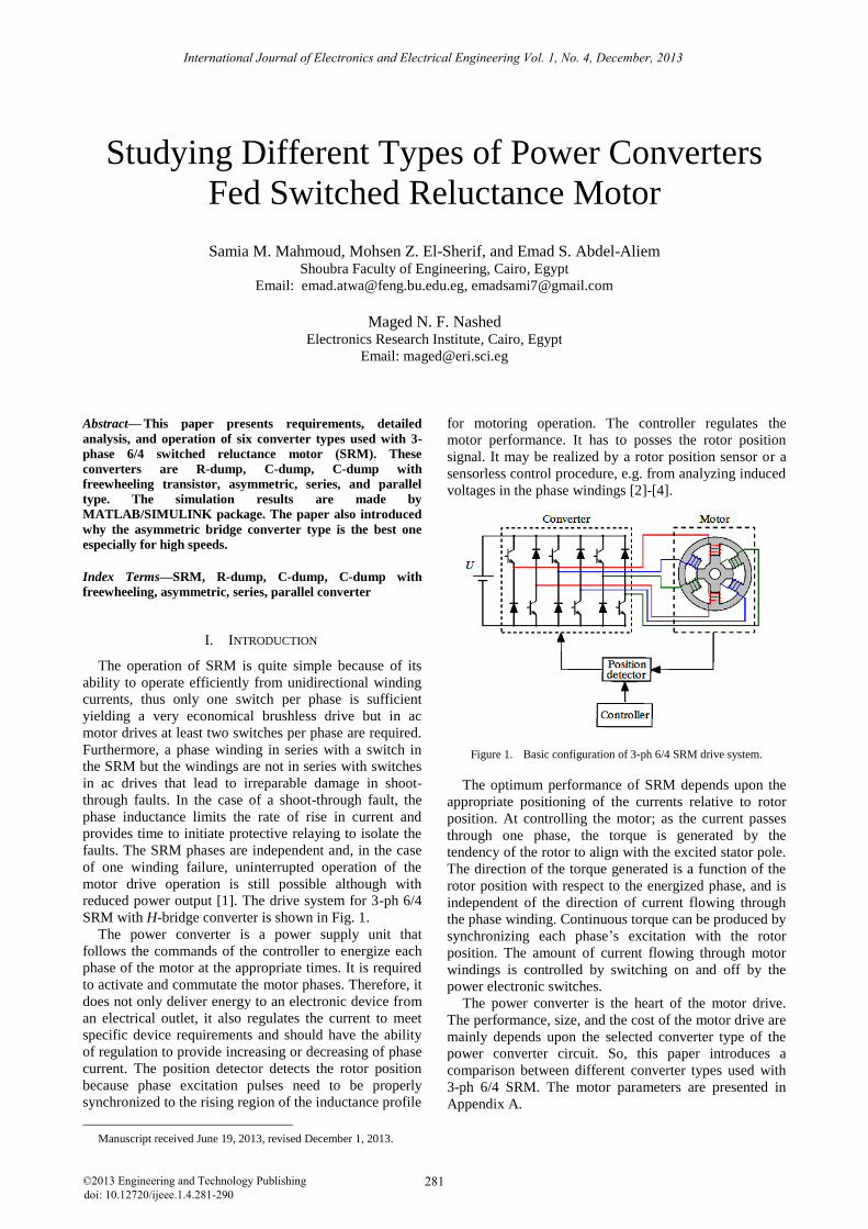
Figure 25. Evolution of energy conversion at using series converter
The complete simulation model using the parallel
converter is shown in Fig. 23. The simulink results of
phases inductance, phases current, total torque, and motor
speed are shown in Fig. 24. The system reachs its steady
speed at a step angle about 5 rad. The simulation results
during steady state shows that the shape of phase
inductance is not distorted. During steady state operation,
the maximum phase current is 2.551 A, the average phase
current is 1.075 A, and the average total torque developed
by motor is 1.904 Nm at 1000 rpm. The evolution of
energy conversion can be represented for phase a by Fig.
25. In both series or parallel converter; the stored energy
of the de-magnetized outgoing winding charges the
incoming phase winding and also the two converter
performances are similar.
The work done and the torque can be evaluated from
the area enclosed between the aligned and unaligned flux
linkages versus excitation current characteristics [28], [4].
The average torque at high speed is reduced and is
deduced from the size of the enclosed surface area
generated by the corresponding flux linkage-current
characteristics. The included area for each speed is
directly proportional to the average torque per phase.
Consequently, an indication of the change in the average
torque with increasing speed may be found by observing
the change of area obtained at any speed. If phase current
or flux linkage ripple is halved, the torque ripple caused
by this current or flux linkage ripple is reduced to one
fourth of the original one because the generated torque is
proportional to the square of the current or the flux
linkage [10], [29].
TABLE II. COMPARISON BETWEEN THE SIMULATION RESULTS
Parameter
Max.
phase
current (A)
Average phase
current (A)
Average total torque
(Nm)
Torque per
ampere
Speed
(rpm)
R-dump 2.435 1.231 1.797 1.460 940
C-dump 2.443 0.905 1.759 1.943 927
C-dump with
freewheel 2.724 1.028 2.099 2.042 1090
Asymmetric 2.379 0.953 1.756 1.843 946
Series 2.575 1.073 1.920 1.789 1000
Parallel 2.551 1.075 1.904 1.771 1000
In all the simulated converters, there is a comparative
evaluation mentioned in Table II. The selection of a
converter, in most of the cases, depends upon the
application. As shown from the comparison of converters
in Table I and the simulation reuslts in Table II. For low
performance applications where precise control of torque
is not required, the low cost dissipative converters; R-
dump, C-dump, and C-dump with freewheeling can be
employed. For high performance and precise applications
where precise torque control and efficiency are important,
the high performance voltage boosting converters;
asymmetric, series, parallel types are used which can
provide fast demagnetization of phases. In the aircraft
applications where the precise operartion is required; the
asymmetric bridge is preferred.
In spite of the properity of torque per ampere for
asymmetric bridge type have intermediate value, but that
converter is the preferred type, because it has the big
288
International Journal of Electronics and Electrical Engineering Vol. 1, No. 4, December, 2013
©2013 Engineering and Technology Publishing
benefits over other types as mentioned in Table I,
specially the fault tolerance capability. So, it is choosen
as the best in aerospace applications to give more safety
for pepole life.
V. CONCLUSIONS
The most flexible and versatile four-quadrant SRM
converter is the asymmetric (classical) converter, which
has the capability of fault tolerance; in the case of one
winding failure, uninterrupted operation with reduced
power output of the motor drive is still possible. By
comparing various converter topologies; it is found that
the asymmetric converter with MOSFETs are suitable for
high speed operation at low power due to the fast fall and
rise time of current and also provide negligible shoot
through fault. But, IGBTs power switches are preferable
for medium speed operation at high power due to their
high input impedance and due to low conduction losses.
APPENDIX A : MOTOR DATA
The parameters of the three phase 6/4 poles SRM are:
Number of motor phases : K = 3
Number of stator poles : NS = 6
Number of rotor poles : NR = 4
Stator pole arc (mech. deg.): βS = 40º
Rotor pole arc (mech. deg.): βR = 45º
DC voltage rating : U = 220 V
Stator phase resistance : R = 17 Ω
Aligned inductance : Lal = 0.605 H
Unaligned inductance : Lul = 0.155 H
Inertia constant : J = 0.0013 Kg.m2
Viscous friction coefficient : B = 0.0183 N.m.Sec2
Rated speed : nr = 1000 rpm
Rated phase current : Iph = 3 A
Rated Torque : Te = 1 Nm
Number of turns per phase : Nph = 600
Winding wire diameter : d = 0.5 mm
Step angle (mech. deg.) : θr = 30º
REFERENCES
[1] T. Wichert, “Design and construction modifications of switched
reluctance machines,” Ph.D. thesis, Warsaw University of
Technology, 2008. [2] Y Hasegawa, K. Nakamura, and O. Ichinokura, “Development of
a switched reluctance motor made of permendur,” in Proc. 2nd Int.
Symp. on Advanced Magnetic Materials and Applications, Journal of Physics, 2011.
[3] M. T. Lamchich, Torque Control, InTech Publisher, February 10 2011, ch. 8.
[4] R. D. Doncker, D. W. J. Pulle, and A. Veltman, Advanced
Electrical Drives: Analysis, Modeling, Control, Springer Press, 2011, ch. 10.
[5] E. S. Elwakil and M. K. Darwish, “Critical review of converter topologies for switched reluctance motor drives,” International
Review of Electrical Engineering, vol. 2, no. 1, January-February
2011. [6] J. W. Ahn, J. Liang, and D. H. Lee, “Classification and analysis of
switched reluctance converters,” Journal of Electrical Engineering & Technology, vol. 5, no. 4, pp. 571-579, 2010.
[7] Ž. Grbo, S. Vukosavić, and E. Levi, “A novel power inverter for
switched reluctance motor drives,” FACTA Universitatis (NIŠ), Elec. Eng., vol. 18, no. 3, pp. 453-465, December 2005.
[8] B. Singh, R. Saxena, Y. Pahariya, and A. R. Chouhan, “Converters performance evaluation of switched reluctance motor in
simulink,” International Journal of Industrial Electronics and Control, vol. 3, no. 2, pp. 89-101, 2011.
[9] P. Vijayraghavan, “Design of switched reluctance motors and
development of a universal controller for switched reluctance and permanent magnet brushless DC motor drives,” Ph.D. dissertation,
Faculty of the Virginia Polytechnic Institute and State University, Blacksburg, Virginia, November 2001.
[10] R. Krishnan, Switched Reluctance Motor Drives: Modeling,
Simulation, Analysis, Design, and Applications, CRC Press 2001. [11] R. Krishnan, and P. N. Materu, “Analysis and design of a low-cost
converter for switched reluctance motor drives,” IEEE Transactions on Industry Applications, vol. 29, no. 2, pp. 320-327,
March/April 1993.
[12] T. J. E. Miller, “Converter volt-ampere requirements of the switched reluctance motor drive,” IEEE Transactions on Industry
Applications, vol. IA-2I. no. 5, pp. 1136-1144, September/October 1985.
[13] T. J. E. Miller, et al., “Regenerative unipolar converter for
switched reluctance motors using one main switching device per phase,” U.S. Patent, Aug. 4 1987.
[14] D. Y. Lee, J. Hur, and D. S. Hyun, “An improved C-dump converter system for switched reluctance motors,” in Proc.
International Conference of Electrical Engineering, 2002, pp.
1027-1030. [15] Y. H. Yoon, Y. C. Kim, S. H. Song, and C. Y. Won, “Control of
C-dump converters fed from switched reluctance motors on an automotive application,” Journal of Power Electronics, vol. 5, no.
2, pp. 120-128, April 2005.
[16] P. K. Sood, “Power converter for a switched reluctance motors using one main switching device per phase,” U.S. Patent, May 19,
1992. [17] H. K. Bae and R. Krishnan, “A study of current controllers and
development of a novel current controller for high performance
SRM drives,” in Proc. Industry Applications Conference, 31st Annual IEEE Meeting, vol. 1, no. 31, pp. 68-75, 1996.
[18] H. K. Bae, B. S. Lee, P. Vijayraghavan, and R. Krishnan, “A linear switched reluctance motor: Converter and control,” in Proc.
Industry Applications Conference, 34th Annual IEEE Meeting, vol.
1, no. 34, 1999, pp. 547-554. [19] S. Singh, “Comparative study of various converter topologies of
switched reluctance motor drive using P-SPICE,” M.sc. thesis,
Thapar University, Patiala, June 2011.
[20] K. Ha, “Position estimation in switched reluctance motor drives
using the first switching harmonics of phase voltage and current,” Ph.D. dissertation, Faculty of the Virginia Polytechnic Institute
and State University, Blacksburg, Virginia, June 2008. [21] J. Kim, K. Ha, and R. Krishnan, “Single-controllable-switch-based
switched reluctance motor drive for low cost, variable-speed
applications,” IEEE Transactions on Power Electronics, vol. 27, no. 1, pp. 379-387, January 2012.
[22] S. Vukosavić and V. R. Stefanović, “SRM inverter topologies: A comparative evaluation,” IEEE Transactions on Industry
Applications, vol. 27, no. 6, pp. 1034-1047, November/December
1991. [23] M. Ahmad, High Performance AC Drives: Modelling Analysis
and Control; Springer Press, 2010, ch. 6. [24] E. Elwakil, “A new converter topology for high speed high
starting torque three-phase switched reluctance motor drive
system,” Ph.D. thesis, Brunel University London, UK, January 2009.
[25] D. H. Lee, J. Liang, T. H. Kim, and J. W. Ahn, “Novel passive boost power converter for SR drive with high demagnetization
voltage,” Dept. of Electrical and Mechatronics Engineering,
Kyungsung University, Korea, 2006. [26] M. Asgar, E. Afjei, A. Siadatan, and A. Zakerolhosseini, “A new
modified asymmetric bridge drive circuit switched reluctance motor,” in Proc. European Conference Circuit Theory and Design,
Aug 2009, pp. 539-542, 23-27.
[27] M. Barnes and C. Pollock, “Power electronic converters for switched reluctance drives,” IEEE Transactions on Power
Electronics, vol. 13, no. 6, pp. 1100-1111, November 1998.
[28] M. Rekik et al., “High speed range enhancement of switched
reluctance motor with continuous mode for automotive
applications,” in Proc. International Conference on Ecologic Vehicles & Renewable Energies, Monaco 2007.
289
International Journal of Electronics and Electrical Engineering Vol. 1, No. 4, December, 2013
©2013 Engineering and Technology Publishing

[29] H. K. Bae, “Control of switched reluctance motors considering mutual inductance,” Ph.D. dissertation, The faculty of the Virginia
Polytechnic Institute and State University, Blacksburg, Virginia,
August 2000.
Mohsen Z. El-Sherif received his B.S. degree in 1970 from Electrical Engineering from El-Mansoura
University, Egypt. In 1975, he worked as an
engineer in Higher-Technical Institute at Shoubra, Egypt. In 1982, he received his M.S. degree from
Cairo University, Egypt. From November 1985 untill May 1987, he worked as a guest researcher at
Kyushu Institute of Technology, Japan. In
December 1987 he received Ph.D. degree inElectrical drives from Cairo University, Egypt. In 1987- 1993, he worked as a Lecturer of Electrical
Engineering and Electrical Machines at Zagazig University, Egypt. In 1993, he worked as Associate Professor at Shoubra Faculity of
Engineering, Zagazig University. In December 1999 he was promoted
to Professor's degree in the same Faculty of Engineering. In 2000 – up till now, he works as a Professor of Electrical Machines at Shoubra
Faculty of Engineering, Benha university, Cairo, Egypt. His current research interests include electrical engineering, power electronics,
electrical machines and drives.
Maged N. F. Nashed received his B.S. degree in
Electrical Engineering, from Menoufia University, Egypt, in May 1983, his Diploma of Higher
Studies from Cairo University, May 1990, his
M.SC. degree in Electrical Engineering, from Ain Shams University, Cairo, Egypt, in April 1995 and
his Ph.D. in Electrical Engineering, from Ain Shams University, Cairo, Egypt, in January 2001.
He was a researcher for Fukuoka Institute of Technology, Japan, 2005. Since 1989, he has been a researcher with the Department of Power
Electronic and Energy Conversion, Electronic Research Institute. Now
he works as associate professor in the same Institute. He is engaged in research on power electronics; drive circuit, control of drives and
renewable energy.
Samia M. Mahmoud received her B.S. degree in 1984 from faculty of Electrical Engineering, Benha
University, Egypt. In November 11, 1999, she received her M.S. from Electrical Engineering and
Electrical Machines at Zagazig University, Egypt.
In October, 2004, she received Ph.D. degree in Electrical Engineering from Benha University,
Egypt. In 2005- till now, she works as a lecturer of Electrical Engineering at Shobra Faculty of Engineering, Benha
University, Cairo, Egypt. Her current research interests include wind
turbine energy, electrical machines and drives.
Emad S. Abdel-Aliem received his B.S. & M.Sc. degree in Electrical Engineering, from Benha
University, Cairo, Egypt, in May 2006 and
December 2011 respectively. He works now on Ph.D. degree from Benha University, Cairo, Egypt.
In 2006–2012 & from 2012 up till now, he works as a demonstrator and an Assistant Lecturer at Shoubra
faculty of engineering, Benha University, Cairo,
Egypt respectively. He has worked extensively in the modeling and studying of stepping motor drives. His research interests include
modeling and control of switched reluctance motor drives, power electronics, and variable speed drives.
290
International Journal of Electronics and Electrical Engineering Vol. 1, No. 4, December, 2013
©2013 Engineering and Technology Publishing
![DAB Converter Based on Unified High-Frequency …...Generally, BDCs include current-fed and voltage-fed converters [6], [7]. In the current-fed BDC, the spike voltage is usually across](https://img.pdfslide.us/doc/110x75/5fd1e3f2a710c80b81223e67/dab-converter-based-on-unified-high-frequency-generally-bdcs-include-current-fed.jpg)