Embed Size (px)
Citation preview

Copyright © 2017, the Authors. Published by Atlantis Press.This is an open access article under the CC BY-NC license (http://creativecommons.org/licenses/by-nc/4.0/).
Study on Longitudinal Stress of Urban Water Supply Network under the Action of
Seismic Wave
Lijuan WANG
School of Civil Engineering and Transportation
Hebei University of Technology
Tianjin, China
e-mail: [email protected]
Xin LIU
School of Civil Engineering and Transportation
Hebei University of Technology
Tianjin, China
e-mail: [email protected]
Jiahui WANG
School of Civil Engineering and Transportation
Hebei University of Technology
Tianjin, China
Ying WANG
School of Civil Engineering and Transportation
Hebei University of Technology
Tianjin, China
Butao JIANG
School of Civil Engineering and Transportation
Hebei University of Technology
Tianjin, China
Xiaoning LI
School of Civil Engineering and Transportation
Hebei University of Technology
Tianjin, China
Abstract—Based on the elastic foundation model and wave
theory as well as fluid mechanics theory, considered of the
influence of flow velocity in the pipe, vertical force of buried
water supply pipeline are analyzed under the action of seismic
wave. The bending moment and stress formula are derived,
and the vertical stress calculation model of water supply
pipeline under the action of seismic wave was established. The
influence of different diameter, flow velocity, soil and
earthquake intensity on the water supply pipeline is analyzed
by numerical examples.
Keywords-water supply pipeline; seismic wave; stress;
calculation model; flow velocity
I. INTRODUCTION
Urban water supply pipe network system is an important part of urban lifeline engineering system. It is easy to be damaged in the earthquake, even paralyzed and may subsequently lead to a variety of secondary disasters, directly affecting the life of people after the earthquake. China is a country with many earthquakes, but its water supply networks for seismic design start late and differ a lot compared with Japan, the United States and other developed countries. Most of the cities' water supply pipe network systems have not been a formal seismic design, and pipeline seismic analysis of the model is still not perfect. Especially water supply pipeline seismic analysis is not comprehensive enough.
Basing on the mutual deformation theory, the relative deformation theory of seismic wave was simplified as a sine wave. That is, fluctuating deformation of the soil is wrapped together with the deformation of the pipeline, under the
action of earthquake wave. But due to the difference of the pipeline stiffness and soil stiffness, there is a relative sliding between the pipe and the surrounding soil, and the relative sliding will make the tube deformation smaller than the deformation of the soil. Based on the elastic foundation model and wave theory as well as fluid mechanics theory, considering the influence of flow velocity for the pipe and analyzing pipe stress when bent and filled with water.
II. ANALYSIS OF VERTICAL DEFORMATION OF WATER
SUPPLY PIPELINE UNDER THE ACTION OF EARTHQUAKE
WAVES
Longitudinal pipeline failure has been recognized as a major failure mode during earthquakes [1] ~ [3]. For the pipeline under dynamic action, the calculation result of the inertia force of the pipe body and water is very close to the result of the static action. Because the inertia of the pipeline is very small [4] ~ [6], it can ignore the dynamic effect, and directly consider the pipeline stress under the static load.
The model simplifies the seismic wave into sine wave, which is easy to be calculated, but in accordance with seismic thinking. So the relevant norms of the United States and China's Code for seismic design of outdoor water supply and gas and thermal power engineering GB50032-2003 [7] are using this method.
A. Basic Assumptions
1) The propagation of seismic wave in soil is
idealized as a sine wave, as shown in the following figure 1:
442
Advances in Engineering Research (AER), volume 722016 International Conference on Architectural Engineering and Civil Engineering (AECE-16)

Figure 1. Effects of seismic ware on buried pipelines
(1)
Where, u is the displacement of soil along the wave propagation direction, L is the wavelength, x is the axial displacement of the wave and u0k is the amplitude. The angle between the direction of the incident wave and the tube axis
is . Vertical decomposition of the seismic wave, then the soil vertical displacement can be expressed as
(2)
2) For the water in the pipeline, it is assumed that the
water is a constant flow, incompressible, non viscous: This assumption implies that the water in the pipe can be
solved according to the correlation equation of the one-dimensional pipe flow in hydraulics.
3) The soil is regarded as elastic material, and the
plastic deformation of the soil is neglected: According to this assumption, can be regarded as soil and
earth between the soil spring link.
B. Vertical Force Balance Equation of Pipeline Unit
Vertical stress model of pipeline unit: as shown in figure 2.
M M+dM
Q Fy
1 2
1 2
P
v
dx
Figure 2. Model of pipe element on the vertical motion
Figure: dx for the length of the pipe unit, the section
bending moment is M, pipe bending deformation , Q for pipe shear, V is the speed of the water flow in the pipeline, P
for water pressure on the inner wall of the pipelines, Fy for soil spring force on the pipeline.
1) Force of water to pipeline: According to the fluid energy conservation equation [10]
(3)
Where, Z1, Z2 respectively for the 1-1 section and 2-2
section of the position of head;
pp 21 , respectively for the 1-1
section and the 2-2 section of the pressure head; gg
vv2
,2
2
2
2
1
respectively for 1-1 section and 2-2 section of the velocity
head; for the head loss along the way, referred to
Assuming the pipeline level and the velocity is constant,
there is = ; = .
Balance equation can be simplified as
In the dynamic case, the inertia effect of the pipeline is very small, that is, the inertia force of the water is very close to that of the static state. The hydrostatic pressure of the water to the pipe wall is
So there
The vertical pressure of the water to the pipe is
443
Advances in Engineering Research (AER), volume 72

2) Vertical force balance equation of pipeline unit: The vertical force balance equation of the pipeline unit is
The relationship between deformation and bending moment of pipe is
Type, M is the moment that the pipeline is subjected to; I is the moment of inertia of the cross section of the pipeline;
the vertical displacement of the pipeline. According to the basic differential relations of material
mechanics,
In the formula, Q is the shear force that the pipeline is subjected to, and Ky is the coefficient of the vertical soil spring for the pipeline unit.
The equilibrium equation of the pipeline is obtained.
Transfer coefficient of soil vertical displacement [8]
When Φ= 0°, the displacement transfer coefficient is maximum, then
3) Vertical stress of pipe unit: Vertical stress suffered by the pipeline
In the formula, it is the bending section coefficient. For a pipeline
(22), (23) into the formula (21) is
III. PARAMETER DETERMINATION
A. Determination of Seismic Wave Amplitude
According to the literature, the amplitude of the seismic wave can be determined by the following equation [7]
Where, α is the horizontal seismic influence coefficient; Tg is the characteristic period of the site soil, depending on the nature of the area and soil.
B. Determination of the Coefficient of Vertical Soil Springs
Method for reference of the value method of vertical soil spring coefficient, Code for seismic design of buried steel pipeline in oil (gas) transportation [9]
444
Advances in Engineering Research (AER), volume 72

In the formula, G′ is the soil shear modulus; ′ is soil
bulk density; g is the acceleration of gravity; is the seismic shear wave velocity.
C. Determination of the Drag Coefficient along the Road
According to the Nikuradse formula
Where, is the equivalent roughness of the pipe. The equivalent roughness of various wall materials is shown in Table I [10].
TABLE I. THE EQUIVALENT ROUGHNESS OF SOME KINDS OF PIPES
Tube wall material
(mm)
PE, aluminum
0.0015~0.015
Welded steel pipe
0.046
Steel, paint 0.06
cast iron
0.3~1.0
Cast iron, asphalt coating
0.12~1.0
Iron, paint
0.15
Cast iron, rust 1.0~1.5
Iron deposit
1.5~3.0
IV. EXAMPLE ANALYSIS
TABLE II. DIAMETER CONTROL TABLE
Pipe diameter Outside diameter of
pipe
D (mm)
Pipe internal
diameter
D (mm)
DN100 118 100
DN200 222 203.4
DN400 429 402.8
DN500 532 504
DN600 635 605.2
DN800 842 806.6
DN1000 1048 1009
TABLE III. DIFFERENT SHEAR WAVE VELOCITY AND
CHARACTERISTIC CYCLE OF DIFFERENT
Soil type Shear wave
velocity (m/s)
Characteristic period
(s)
I type soil 600 0.25
II type soil 300 0.35
IIItype soil 200 0.45
IVtype soil
100 0.65
TABLE IV. MAXIMUM VALUE OF HORIZONTAL EARTHQUAKE
INFLUENCE COEFFICIENT
earthquake
intensity
6 degrees
7 degrees
8 degrees
9 degrees
α 0.04 0.12 0.24 0.32
TABLE V. PARAMETER CONTROL TABLE
Elastic
modulu
E (N/mm2)
Incident angle
of seismic
wave (°)
Equivalent
roughness of
pipe
(mm)
Soil bulk
density
(N/m3)
1.6×10^5 45 0.7 3×10^(-3)
In this paper, the cast iron pipe produced by Xinxing
Ductile Iron Pipe Co., Ltd is taken as an example to calculate the vertical force of the pipe considering water and not considering the water pipe, considering the effect of water velocity on the pipeline's stress, and the stress of pipelines varies with seismic intensity, soil quality and pipe diameter in both cases. The inner and outer diameters of each pipe are shown in Table II, and the other parameters are shown in Table III, Table IV, and Table V.
A. Numerical Example 1
Assuming that the pipe is in the third category of soil, the vertical force of the pipe is calculated as v=0.8m/s, v=1m/s, v=1.2m/s and there is no water in the pipe when seismic intensity changing.
6 7 8 90.0
0.5
1.0
1.5
2.0
2.5
3.0
vert
ical
stre
ss(M
Pa)
seismic intensity(degree)
without water
0.8(m/s) v=1(m/s)
v=1.2(m/s)
Figure 3. Relationship between vertical stress and seismic intensity of pipeline DN100
445
Advances in Engineering Research (AER), volume 72

6 7 8 90.00
0.02
0.04
0.06
0.08V
erti
cal
stre
ss(M
pa)
seismic intensity(degree)
without water
v=0.8(m/s)
v=(1m/s)
v=(1.2m/s)
Figure 4. Relationship between vertical stress and seismic intensity of pipeline DN500
6 7 8 90.000
0.003
0.006
0.009
0.012
0.015
Vert
ical
stre
ss(M
Pa)
seismic intensity(degree)
without water
v=0.8(m/s)
v=1.0(m/s)
v=1.2(m/s)
Figure 5. Relationship between vertical stress and seismic intensity of pipeline DN1000
Figure 3-5 shows: The greater the seismic intensity, the greater the vertical force of the pipeline; When the pipeline filled with water, the vertical force is greater than no water; With the increase of flow velocity, the vertical force of pipeline is more and more; The higher the flow velocity, the more obviously the vertical force of the pipeline changes with the increasing of seismic intensity; The greater the seismic intensity, the greater the influence of the flow velocity on the vertical force of the pipeline.
B. Example 2
Earthquake intensity is 8 degrees, and the vertical force of the pipeline filled water and without water, which changes with the site soil type, is calculated when the water velocity is v = 0.8m /s, v = 1m /s, v = 1.2m /s respectively. Diameter DN100, DN500, DN1000, pipe vertical force results as shown below
1 2 3 40
1
2
3
4
5
6
Vert
ical
stre
ss (
Mp
a)
Soil type
without water
v=(0.8m/s)
v=(1.0m/s)
v=(1.2m/s)
Figure 6. The relationship between vertical stress and soil type of DN100
pipeline
1 2 3 40.00
0.02
0.04
0.06
0.08
0.10
0.12
0.14
0.16
0.18
Vert
ical
stre
ss (
Mp
a)
soil type
without water
v=0.8(m/s)
v=1.0(m/s)
v=1.2(m/s)
Figure 7. The relationship between vertical stress and soil type of DN500 pipeline
1 2 3 4
0.004
0.008
0.012
0.016
0.020
0.024
0.028
0.032
Vert
ical
stre
ss (
Mp
a)
soil type
without water
v=0.8(m/s)
v=1.0(m/s)
v=1.2(m/s)
Figure 8. The relationship between vertical stress and soil type of DN1000 pipeline
Figure 6-8 shows: The more soft the soil of the site, the smaller the vertical force pipeline; When the pipeline filled with water, the vertical force was greater than no water; With the increase of flow velocity, the vertical force of pipeline is more and more. The higher the flow velocity, the more obvious the vertical force of the pipeline decreases with the
446
Advances in Engineering Research (AER), volume 72
soil softening. With the softening of the soil, the impact of the pipe flow velocity on the pipeline is less obvious.
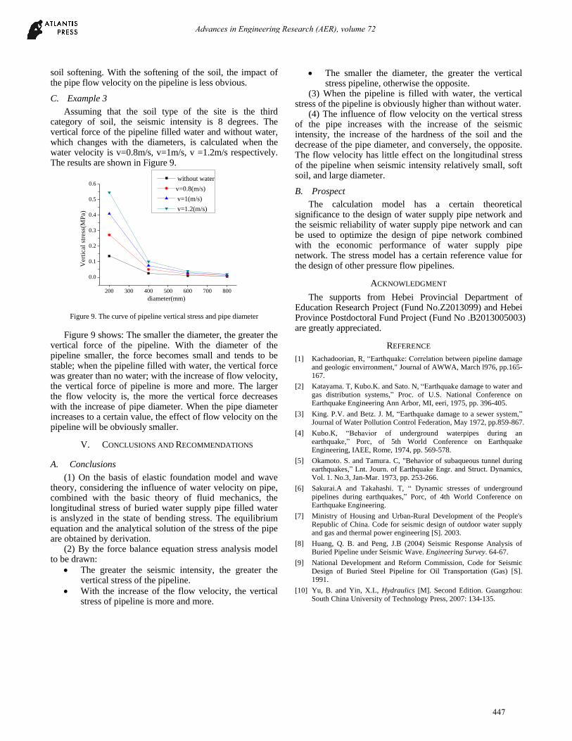
C. Example 3
Assuming that the soil type of the site is the third category of soil, the seismic intensity is 8 degrees. The vertical force of the pipeline filled water and without water, which changes with the diameters, is calculated when the water velocity is v=0.8m/s, v=1m/s, v =1.2m/s respectively. The results are shown in Figure 9.
200 300 400 500 600 700 800
0.0
0.1
0.2
0.3
0.4
0.5
0.6
Vert
ical
stre
ss(M
Pa)
diameter(mm)
without water
v=0.8(m/s)
v=1(m/s)
v=1.2(m/s)
Figure 9. The curve of pipeline vertical stress and pipe diameter
Figure 9 shows: The smaller the diameter, the greater the vertical force of the pipeline. With the diameter of the pipeline smaller, the force becomes small and tends to be stable; when the pipeline filled with water, the vertical force was greater than no water; with the increase of flow velocity, the vertical force of pipeline is more and more. The larger the flow velocity is, the more the vertical force decreases with the increase of pipe diameter. When the pipe diameter increases to a certain value, the effect of flow velocity on the pipeline will be obviously smaller.
V. CONCLUSIONS AND RECOMMENDATIONS
A. Conclusions
(1) On the basis of elastic foundation model and wave theory, considering the influence of water velocity on pipe, combined with the basic theory of fluid mechanics, the longitudinal stress of buried water supply pipe filled water is anslyzed in the state of bending stress. The equilibrium equation and the analytical solution of the stress of the pipe are obtained by derivation.
(2) By the force balance equation stress analysis model to be drawn:
The greater the seismic intensity, the greater the vertical stress of the pipeline.
With the increase of the flow velocity, the vertical stress of pipeline is more and more.
The smaller the diameter, the greater the vertical stress pipeline, otherwise the opposite.
(3) When the pipeline is filled with water, the vertical stress of the pipeline is obviously higher than without water.
(4) The influence of flow velocity on the vertical stress of the pipe increases with the increase of the seismic intensity, the increase of the hardness of the soil and the decrease of the pipe diameter, and conversely, the opposite. The flow velocity has little effect on the longitudinal stress of the pipeline when seismic intensity relatively small, soft soil, and large diameter.
B. Prospect
The calculation model has a certain theoretical significance to the design of water supply pipe network and the seismic reliability of water supply pipe network and can be used to optimize the design of pipe network combined with the economic performance of water supply pipe network. The stress model has a certain reference value for the design of other pressure flow pipelines.
ACKNOWLEDGMENT
The supports from Hebei Provincial Department of Education Research Project (Fund No.Z2013099) and Hebei Province Postdoctoral Fund Project (Fund No .B2013005003) are greatly appreciated.
REFERENCE
[1] Kachadoorian, R, “Earthquake: Correlation between pipeline damage and geologic envirronment," Journal of AWWA, March l976, pp.165-167.
[2] Katayama. T, Kubo.K. and Sato. N, “Earthquake damage to water and gas distribution systems,” Proc. of U.S. National Conference on Earthquake Engineering Ann Arbor, MI, eeri, 1975, pp. 396-405.
[3] King. P.V. and Betz. J. M, “Earthquake damage to a sewer system,” Journal of Water Pollution Control Federation, May 1972, pp.859-867.
[4] Kubo.K, “Behavior of underground waterpipes during an earthquake,” Porc, of 5th World Conference on Earthquake Engineering, IAEE, Rome, 1974, pp. 569-578.
[5] Okamoto. S. and Tamura. C, "Behavior of subaqueous tunnel during earthquakes,” Lnt. Journ. of Earthquake Engr. and Struct. Dynamics, Vol. 1. No.3, Jan-Mar. 1973, pp. 253-266.
[6] Sakurai.A and Takahashi. T, “ Dynamic stresses of underground pipelines during earthquakes,” Porc, of 4th World Conference on Earthquake Engineering.
[7] Ministry of Housing and Urban-Rural Development of the People's Republic of China. Code for seismic design of outdoor water supply and gas and thermal power engineering [S]. 2003.
[8] Huang, Q. B. and Peng, J.B (2004) Seismic Response Analysis of Buried Pipeline under Seismic Wave. Engineering Survey. 64-67.
[9] National Development and Reform Commission, Code for Seismic Design of Buried Steel Pipeline for Oil Transportation (Gas) [S]. 1991.
[10] Yu, B. and Yin, X.L, Hydraulics [M]. Second Edition. Guangzhou: South China University of Technology Press, 2007: 134-135.
447
Advances in Engineering Research (AER), volume 72