Embed Size (px)
DESCRIPTION
Abstract 2 Circuits Construction and Parameters Design School of Automation and Information Engineering, Xi’an University of Technology, Xi’an, China Email: [email protected] r L Ls r L Cs ICIEA 2006 0-7803-9514-X/06/$20.00 ©2006 IEEE Fig.1 Voltage-source induction heating circuit Fig.2 The topology of three order resonant circuit Tank A C C Ls B
Citation preview
0-7803-9514-X/06/$20.00 ©2006 IEEE ICIEA 2006
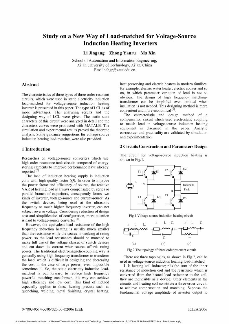
Study on a New Way of Load-matched for Voltage-Source Induction Heating Inverters Li Jingang Zhong Yanru Ma Xin
School of Automation and Information Engineering, Xi’an University of Technology, Xi’an, China
Email: [email protected]
Abstract The characteristics of three types of three-order resonant circuits, which were used in static electricity induction load-matched for voltage-source induction heating inverter is presented in this paper. The type of LCL is of more advantages. The analysing results and the designing way of LCL were given. The static state characters of this circuit were analyzed in detail and the characters curves were protracted with MATALB. The simulation and experimental results proved the theoretic analysis. Some guidance suggestions for voltage-source induction heating load-matched were also provided. 1 Introduction Researches on voltage-source converters which use high order resonance tank circuits composed of energy storing elements to improve performance have already reported [2].
The load of induction heating supply is induction coils with high quality factor (Q). In order to improve the power factor and efficiency of source, the reactive VAR of heating load is always compensated by series or parallel branch of capacitors, consequently forms two kinds of inverter, voltage-source and current-source. As the switch devices, being used at the ultrasonic frequency or much higher frequency inverter, can not subject reverse voltage. Considering reduction of design cost and simplification of configuration, more attention is paid to voltage-source converter [3].
However, the equivalent load resistance of the high frequency induction heating is usually much smaller than the resistance while the source is working at rating power, so the load resistances should be matched to make full use of the voltage classes of switch devices and cut down its current when source affords rating power. The traditional electromagnetic-coupling way is generally using high frequency transformer to transform the load, which is difficult in designing and decreasing the cost in the case of large power, even impossible sometimes [3]. So, the static electricity induction load-matched is put forward to replace high frequency powerful matching transformer, this way can achieve high efficiency and low cost. This kind of method especially applies to those heating process such as quenching, welding, metal finishing, crystal heating,
heat preserving and electric heaters in modern families, for example, electric water heater, electric cooker and so on, in which parameter variation of load is not so obvious. The design of high frequency matching-transformer can be simplified even omitted when insulation is not needed. This designing method is more convenient and more economical [3].
The characteristic and design method of a compensation circuit which used electrostatic coupling to match load in voltage-source induction heating equipment is discussed in the paper. Analytic correctness and practicality are validated by simulation and experimentation.
2 Circuits Construction and Parameters Design
The circuit for voltage-source induction heating is shown in Fig.1.
There are three topologies, as shown in Fig 2, can be
used in voltage-source induction heating load-matched. L is heating coil inductor; r is the sum of the inner
resistance of induction coil and the resistance which is converted from the heated load resistance to the coil, they are indivisible as a device. Other elements in the circuits and heating coil constitute a three-order circuit, to achieve compensation and matching. Suppose the fundamental voltage amplitude of inverter output to
B
T2 D2
T3 D3 T4 D4
T1 D1
Ud Resonant Tank
A
Fig.1 Voltage-source induction heating circuit
(a) (b) (c)
Fig.2 The topology of three order resonant circuit
C
r L Ls
C
r L Cs
Ls
r L C
Authorized licensed use limited to: National Taiwan Univ of Science and Technology. Downloaded on May 17, 2009 at 09:16 from IEEE Xplore. Restrictions apply.
resonant tank is Um, the load resistance when the source provides rating power is R, d=r/R, the rating resonance frequency of inverter is ω0, quality factor of load coil is Q=ω0L/r.
Tank current and voltage are in phase when inverter works in resonance condition. Conclusion was given by analysis , in Fig 2(a) load resistance can match at the range : )r1(QR 2 +< , in Fig 2(b): )r1(QRr 2 +<< , and topology 2(c), its matching result satisfies: R<r. The voltage source induction heating supply generally required the condition of R>r. The LCL type topology of Fig 2(c) cannot satisfy this demand. It is obviously for the inverter that the Fig 2(b) LCC topology exists two series capacitances load, which will generate current impulse on switch devices. Especially existing instantaneous short circuit, it’s unallowed in voltage inverter.
The characteristic of LCL type circuit topology as in Fig 2(a) will be mainly discussed in this paper. Consider fundamental harmonic only, following relations can be got.
The reactance of circuit:
In resonance condition:
Suppose: Resonance frequency:
Matching inductance:
Matching capacitance:
3 Static State Characteristics Analyses 3.1 Response at Different Frequencies For simplifying representation, make a hypothesis as following:
For any operating frequency ω, the reactance can be
expressed as:
(4)w
wke-eQ-n1jnQrwrZ
22 ++=
Then:
[ ]
(5)w
wke)eQn1(Qn1r
|Z|222222 +−−+
=
Analysing the Equation(5), the conclusion is given that, toward high order harmonic resonance tank put up higher impedance characteristic than toward fundamental wave, so the error in analyzing circuit characteristics and inverter equation with omitting high order harmonic and considering fundamental wave only is less than the one when the excitation of inverter is square wave. Thus, the matching element calculating formula as (2) and (3) presented is reasonable.
Suppose impedance angle of matching circuit is ψ, from, then:
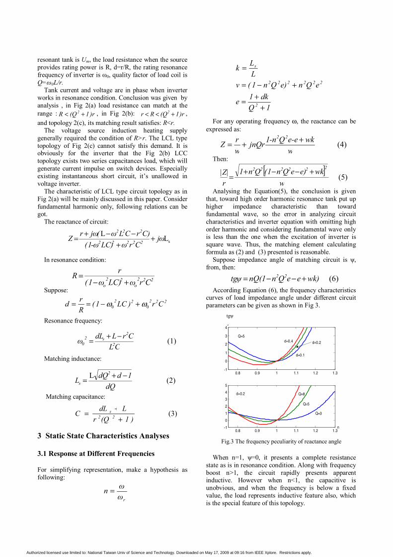
According Equation (6), the frequency characteristics
curves of load impedance angle under different circuit parameters can be given as shown in Fig 3.
When n=1, ψ=0, it presents a complete resistance
state as is in resonance condition. Along with frequency boost n>1, the circuit rapidly presents apparent inductive. However when n<1, the capacitive is unobvious, and when the frequency is below a fixed value, the load represents inductive feature also, which is the special feature of this topology.
(6)wk)eeQn1nQ(tgψ 22 +−−=
0.8 0.9 1 1.1 1.2 1.3-1
0
1
2
3
4
0.8 0.9 1 1.1 1.2 1.3-1
0
1
2
3
4
5
d=0.1
d=0.4 d=0.2
Q=5
d=0.2
Q=3
Q=5
Q=8
n
tg
Fig.3 The frequency peculiarity of reactance angle
tgψ
sLL jωCrωLC)-ω1(
C)rCLω(jωrZ 22222
222
++
−−+=
(1)CL
CrLdLω 2
2s2
0−+=
(3))1(Qr
LdLC 22s
++
=
222o
22o CrωLC)ω1(
rR+−
=
(2)LdQ
1ddQL2
s−+=
rωωn =
22222 Cr)LC1(Rrd 00 ωω +−==
1Qdk1e
eQne)Qn1(vLLk
2
222222
s
++=
+−=
=
Authorized licensed use limited to: National Taiwan Univ of Science and Technology. Downloaded on May 17, 2009 at 09:16 from IEEE Xplore. Restrictions apply.
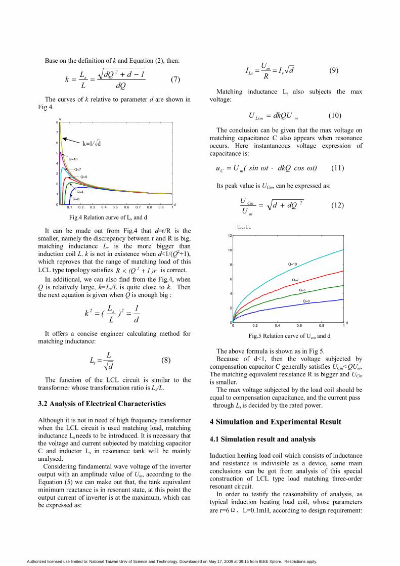
Base on the definition of k and Equation (2), then: The curves of k relative to parameter d are shown in
Fig 4. It can be made out from Fig.4 that d=r/R is the
smaller, namely the discrepancy between r and R is big, matching inductance Ls is the more bigger than induction coil L. k is not in existence when d<1/(Q2+1), which reproves that the range of matching load of this LCL type topology satisfies )r1(QR 2 +< is correct.
In additional, we can also find from the Fig.4, when Q is relatively large, k=Ls/L is quite close to k. Then the next equation is given when Q is enough big :
It offers a concise engineer calculating method for
matching inductance:
The function of the LCL circuit is similar to the
transformer whose transformation ratio is Ls/L. 3.2 Analysis of Electrical Characteristics Although it is not in need of high frequency transformer when the LCL circuit is used matching load, matching inductance Ls needs to be introduced. It is necessary that the voltage and current subjected by matching capacitor C and inductor Ls in resonance tank will be mainly analysed. Considering fundamental wave voltage of the inverter output with an amplitude value of Um, according to the Equation (5) we can make out that, the tank equivalent minimum reactance is in resonant state, at this point the output current of inverter is at the maximum, which can be expressed as:
Matching inductance Ls also subjects the max
voltage:
The conclusion can be given that the max voltage on
matching capacitance C also appears when resonance occurs. Here instantaneous voltage expression of capacitance is:
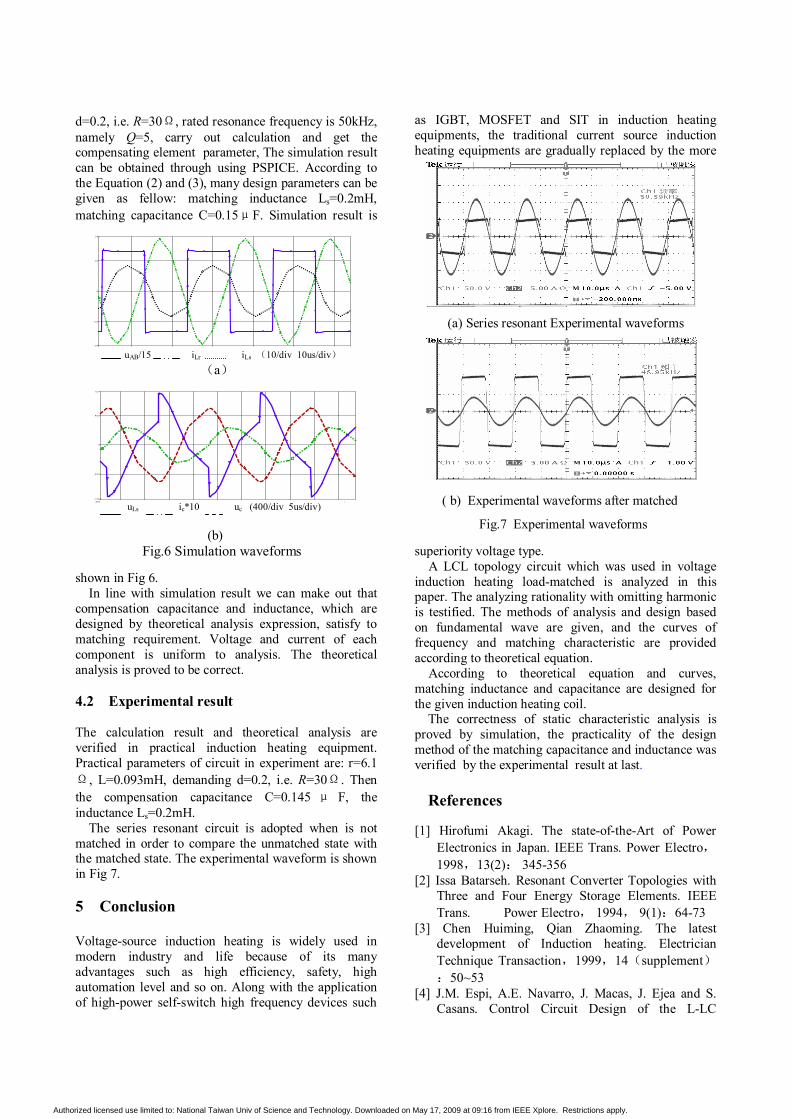
Its peak value is UCm, can be expressed as:
The above formula is shown as in Fig 5. Because of d<1, then the voltage subjected by
compensation capacitor C generally satisfies UCm<QUm. The matching equivalent resistance R is bigger and UCm is smaller.
The max voltage subjected by the load coil should be equal to compensation capacitance, and the current pass through Ls is decided by the rated power. 4 Simulation and Experimental Result 4.1 Simulation result and analysis Induction heating load coil which consists of inductance and resistance is indivisible as a device, some main conclusions can be got from analysis of this special construction of LCL type load matching three-order resonant circuit.
In order to testify the reasonability of analysis, as typical induction heating load coil, whose parameters are r=6Ω、L=0.1mH, according to design requirement:
UCm/Um
0 0.2 0.4 0.6 0.8 10
2
4
6
8
10
12
Q=3
Q=10
Q=7
Q=5
d
Fig.5 Relation curve of Ucm and d
0.1 0.2 0.3 0.4 0.5 0.6 0.7 0.8 0.9 10
1
2
3
4
5
6
7
8
Q=10
Q=7
Q=5
Q=4
Q=3
d
k
Fig.4 Relation curve of Ls and d
d1k /=
(7)dQ
1ddQLLk
2s −+==
d1)
LL(k 2s2 ==
(11)ωt)cosdkQωtsin(Uu mC +=
(10)mLsm dkQUU =
(8)dLLs =
(9)dIR
UI rm
Ls ==
(12)2
m
Cm dQdUU +=
Authorized licensed use limited to: National Taiwan Univ of Science and Technology. Downloaded on May 17, 2009 at 09:16 from IEEE Xplore. Restrictions apply.
d=0.2, i.e. R=30Ω, rated resonance frequency is 50kHz, namely Q=5, carry out calculation and get the compensating element parameter, The simulation result can be obtained through using PSPICE. According to the Equation (2) and (3), many design parameters can be given as fellow: matching inductance Ls=0.2mH, matching capacitance C=0.15μF. Simulation result is
shown in Fig 6. In line with simulation result we can make out that
compensation capacitance and inductance, which are designed by theoretical analysis expression, satisfy to matching requirement. Voltage and current of each component is uniform to analysis. The theoretical analysis is proved to be correct.
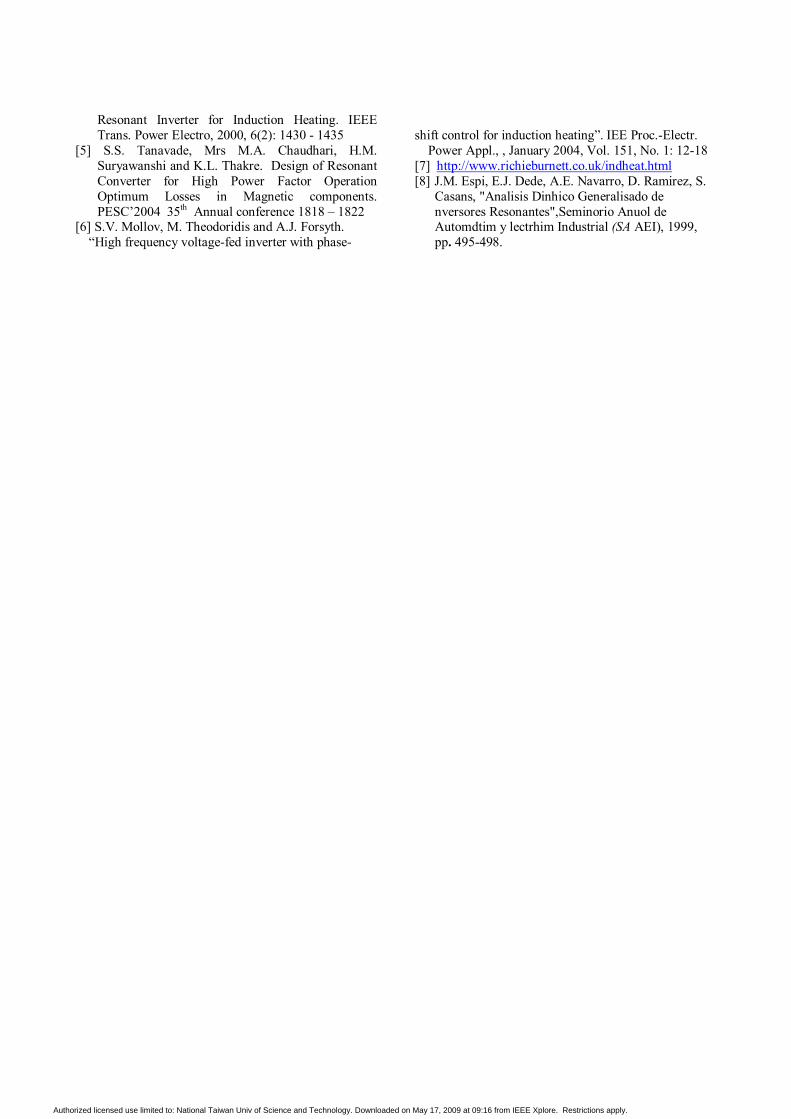
4.2 Experimental result The calculation result and theoretical analysis are verified in practical induction heating equipment. Practical parameters of circuit in experiment are: r=6.1Ω, L=0.093mH, demanding d=0.2, i.e. R=30Ω. Then the compensation capacitance C=0.145 μ F, the inductance Ls=0.2mH.
The series resonant circuit is adopted when is not matched in order to compare the unmatched state with the matched state. The experimental waveform is shown in Fig 7.
5 Conclusion Voltage-source induction heating is widely used in modern industry and life because of its many advantages such as high efficiency, safety, high automation level and so on. Along with the application of high-power self-switch high frequency devices such
as IGBT, MOSFET and SIT in induction heating equipments, the traditional current source induction heating equipments are gradually replaced by the more
superiority voltage type. A LCL topology circuit which was used in voltage induction heating load-matched is analyzed in this paper. The analyzing rationality with omitting harmonic is testified. The methods of analysis and design based on fundamental wave are given, and the curves of frequency and matching characteristic are provided according to theoretical equation. According to theoretical equation and curves, matching inductance and capacitance are designed for the given induction heating coil.
The correctness of static characteristic analysis is proved by simulation, the practicality of the design method of the matching capacitance and inductance was verified by the experimental result at last.
References
[1] Hirofumi Akagi. The state-of-the-Art of Power
Electronics in Japan. IEEE Trans. Power Electro,1998,13(2): 345-356
[2] Issa Batarseh. Resonant Converter Topologies with Three and Four Energy Storage Elements. IEEE Trans. Power Electro, 1994, 9(1):64-73
[3] Chen Huiming, Qian Zhaoming. The latest development of Induction heating. Electrician Technique Transaction,1999,14(supplement):50~53
[4] J.M. Espi, A.E. Navarro, J. Macas, J. Ejea and S. Casans. Control Circuit Design of the L-LC
Time
900us 910us 920us 930us 940us 950us892us 954usI(L1) I(L5) V(Z1:E) /15- V(Z2:E)/15
-10
0
10
-18
18
uAB/15 iLr iLs (10/div 10us/div)
(a)
Time
885.0us 890.0us 895.0us 900.0us 905.0us 910.0us 915.0us 920.0us 925.0us 930.0us880.9usI(C1)*10 V(C1:2) - V(C1:1) V(L5:1) - V(L5:2)
-400
0
400
-738
727
uLs ic*10 uc (400/div 5us/div)
(b) Fig.6 Simulation waveforms
(a) Series resonant Experimental waveforms
( b) Experimental waveforms after matched
Fig.7 Experimental waveforms
Authorized licensed use limited to: National Taiwan Univ of Science and Technology. Downloaded on May 17, 2009 at 09:16 from IEEE Xplore. Restrictions apply.
Resonant Inverter for Induction Heating. IEEE Trans. Power Electro, 2000, 6(2): 1430 - 1435
[5] S.S. Tanavade, Mrs M.A. Chaudhari, H.M. Suryawanshi and K.L. Thakre. Design of Resonant Converter for High Power Factor Operation Optimum Losses in Magnetic components. PESC’2004 35th Annual conference 1818 – 1822
[6] S.V. Mollov, M. Theodoridis and A.J. Forsyth. “High frequency voltage-fed inverter with phase-
shift control for induction heating”. IEE Proc.-Electr.
Power Appl., , January 2004, Vol. 151, No. 1: 12-18 [7] http://www.richieburnett.co.uk/indheat.html [8] J.M. Espi, E.J. Dede, A.E. Navarro, D. Ramirez, S.
Casans, "Analisis Dinhico Generalisado de nversores Resonantes",Seminorio Anuol de Automdtim y lectrhim Industrial (SA AEI), 1999, pp. 495-498.
Authorized licensed use limited to: National Taiwan Univ of Science and Technology. Downloaded on May 17, 2009 at 09:16 from IEEE Xplore. Restrictions apply.