Embed Size (px)
Citation preview

STUDY OF PARAMETERS IMPACTING PRODUCTIVITY
OF TUNNEL BORING MACHINES
By
HAMED HASHEM POUR
Presented to the Faculty of the Graduate School of
The University of Texas at Arlington in partial Fulfillment
Of the Requirements
For the Degree of
MASTER OF SCIENCE IN CIVIL ENGINEERING
THE UNIVERSITY OF TEXAS AT ARLINGTON
December 2016

ii
Copyright © by HAMED HASHEM POUR 2016
All Rights Reserved
Hamed Hashem pour 2016

iii
Acknowledgements
I would like to acknowledge the support and help I have received from my professors and
classmates throughout my graduate career. Specifically, I would like to thank Dr.
Mohammad Najafi, director of the Construction Engineering and Management areas and
director of the Center for Underground Infrastructure Research and Education (CUIRE)
for his guidance and support to prepare this thesis. Dr. Najafi has guided me from the
beginning of my graduate career, leading with coursework matters. His insight has
significantly assisted me in choosing my career path, presently and in the future and
without him, this research would not have been possible. I would like to thank Dr. Ali
Abolmaali for believing in me and supporting me.
I would like to thank Dr. Raad Azzawi, Dr. Nilo Tsung and Dr. Mohsen Shahandashti for
their encouragement, insightful comments, and questions. I would like to thank Mr. Saeed
Janbaz (Ph.D. student at the University of Texas at Arlington) for helping me patiently. I
would like to thank my parents and my family for their love and support of my graduate
studies at the University of Texas at Arlington.
DECEMBER 16, 2016

iv
Abstract
STUDY OF PARAMETERS IMPACTING PRODUCTIVITY
OF TUNNEL BORING MACHINES
Hamed Hashem Pour, MS
The University of Texas at Arlington, 2016
Supervising Professor: Mohammad Najafi
Tunnel construction has been on the rise for transportation of humans, freight and fluids.
For a successful tunneling project, tunneling contractors must have sufficient data about
scope of work, project features and characteristics of the ground to estimate the
advance rate of a tunnel boring machine (TBM). The main objective of this thesis is to
study tunneling case histories and literature to analyze TBM productivity based on
ground conditions, diameter and the duration of each project. Project data was tabulated
and results are reported in this thesis. The methodology used to conduct the literature
relied on databases such as ProQuest, Engineering Village, Science Direct, Google
Scholar, and ASCE Library. Additionally, Tunnels and Tunneling International Magazine
as well as TBM manufactures’ websites were studied. The conclusions of this thesis
show that in-depth ground investigations, such as using pilot tunnels, will improve
construction productivity of tunnel operations. Other factors impacting productivity
include compressive strength of rocks or hard ground, rock abrasivity, tunnel diameter,
location of project (whether urban or rural), and other factors as determined in this
thesis.

v
Table of Content
Acknowledgements ............................................................................................................. iii
Abstract .............................................................................................................................. iv
Table of Content .................................................................................................................. v
List of Tables ..................................................................................................................... viii
List Of Illustrations .............................................................................................................. ix
Chapter 1 Introduction and Background ........................................................................... 11
1.1 Introduction ............................................................................................................. 11
1.2 TBM and SBU Background .................................................................................... 12
1.3 Tunnel Boring Machine Parts ................................................................................. 17
1.4 Factors Which Influence Tunneling Advance Rate in Hard Ground ...................... 22
1.5 Face Pressure ........................................................................................................ 23
1.6 TBM Performance................................................................................................... 24
1.7 Scheduling a Tunneling Project .............................................................................. 27
1.8 Functions of a Typical Tunnel Boring Machine ...................................................... 27
1.9 Soil and Rock Groups ............................................................................................. 29
1.10 Objectives ............................................................................................................. 31
1.11 Need Statement .................................................................................................... 31
1.12 Expected Results .................................................................................................. 31
1.13 Methodology ......................................................................................................... 31
1.14 Chapter Summary ................................................................................................ 33
Chapter 2 Literature Review ............................................................................................. 34
2.1 Introduction ............................................................................................................. 34

vi
2.2 Analysis and Prediction of TBM Performance ........................................................ 34
2.2.1 TBM Selection ................................................................................................. 34
2.2.2 Performance of New TBM Versus Refurbished TBM ...................................... 34
2.2.3 Influential Parameters in TBM Performance ................................................... 35
2.2.4 Predicting Productivity ..................................................................................... 36
2.3 Geological Condition in Tunneling Projects ............................................................ 37
2.3.1 Geological Uncertainty .................................................................................... 37
2.3.2 Site Investigation and Inspection ..................................................................... 38
2.4 Management and Decision Making ........................................................................ 39
2.4.1 Decision Making .............................................................................................. 39
2.4.2 Management .................................................................................................... 39
2.26 Chapter Summary ................................................................................................ 40
Chapter 3 Case Study Evaluation ..................................................................................... 41
3.1 Introduction ............................................................................................................. 41
3.2 La Réunion Irrigation Project .................................................................................. 41
3.3 Alimineti Madhava Reddy (AMR) Project ............................................................... 42
3.4 The Mill Creek II Sanitary Sewer Storage Tunnel .................................................. 43
3.5 The Yellow River Water Diversion Project ............................................................. 43
3.6 Cobb County ........................................................................................................... 45
3.7 East Side Access Project ....................................................................................... 46
3.8 Hong Kong Cable Tunnel ....................................................................................... 47
3.9 Kárahnjúkar Hydropower Project ............................................................................ 47
3.10 Little Calumet ........................................................................................................ 48
3.11 Olmos Trans-Andean Tunnel ............................................................................... 49
3.12 Pahang Selangor Raw Water Tunnel ................................................................... 50

vii
3.13 West Qinling Rail Tunnels .................................................................................... 51
3.14 Center for Underground Infrastructure Research and Education ......................... 52
3.15 Shayler Run Segment C Sewer Replacement Project ......................................... 53
3.16 City of Clinton Contract B Force Main Project ...................................................... 54
3.17 Tahoe Forest Hospital District Central Energy Plant Prep Project ....................... 55
3.18 Chester Boulevard Interceptor Sewer .................................................................. 55
3.19 Milford Haven Gas Connection Project ................................................................ 56
3.20 Kota City Water Supply Project ............................................................................ 57
3.21 Glenwood Cable Tunnel ....................................................................................... 57
3.22 Locust Street Sanitary Improvements Project ...................................................... 58
3.23 North Carolina Project .......................................................................................... 58
3.24 Big Sky .................................................................................................................. 59
3.25 Summary of Case Studies .................................................................................... 60
3.26 Discussion of Case Studies .................................................................................. 65
3.24 Chapter Summary ................................................................................................ 66
Chapter 4 Conclusions and Recommendation for Future Research ................................ 67
4.1 Introduction ............................................................................................................. 67
4.2 Conclusions ............................................................................................................ 67
4.3 Recommendation for Future Research .................................................................. 68
References ................................................................................................................... 69
Appendix A ........................................................................................................................ 73
List of Acronyms ........................................................................................................... 73
Appendix B ........................................................................................................................ 76
List of Definitions .......................................................................................................... 76
Biographical Information ................................................................................................... 80

viii
List of Tables
Table 1-1 TBM advantages and limitations....................................................................... 16
Table 1-2 Review of some TBM performance Prediction Models..................................... 26
Table 1-3 Classification of ground based on UCS ............................................................ 30
Table 3-1 CUIRE case study analysis report .................................................................... 52
Table 3-1 Summary of case studies for medium and large diameters TBMs ................... 60
Table 3-1 Continued .......................................................................................................... 61
Table 3-1 Continued .......................................................................................................... 62
Table 3-2 Summary of case studies for SBUs .................................................................. 63
Table 3-2 Continued .......................................................................................................... 64

ix
List of Illustrations
Figure 1-1 General classification of TBMs for various ground conditions ....................... 15
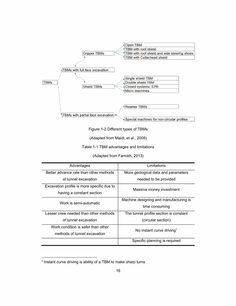
Figure 1-2 Different types of TBMs ................................................................................... 16
Figure 1-3 SBU cutterhead attachment ............................................................................ 17
Figure 1-4 Side view of a typical SBU-M and HAB machine ............................................ 17
Figure 1-5 System group of a tunnel boring machine ....................................................... 21
Figure 1-6 Basic supports to stabilize an excavated tunnel .............................................. 21
Figure 1-7 Schematic operation of TBM under the water level with ground freezing ....... 22
Figure 1-8 Factors influencing tunneling advance for hard ground .................................. 23
Figure 1-9 Face pressure distribution ............................................................................... 24
Figure 1-10 Thesis Methodology ...................................................................................... 32

x
This Page is Intentionally Left Blank
11
Chapter 1
Introduction and Background
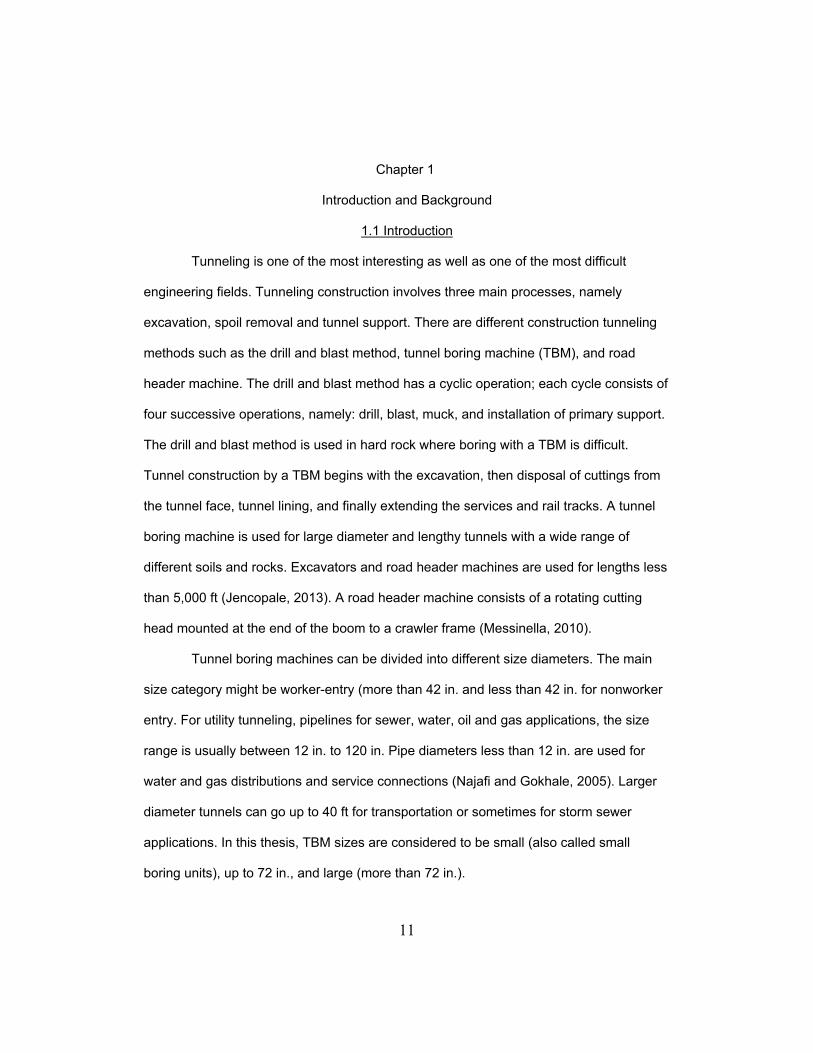
1.1 Introduction
Tunneling is one of the most interesting as well as one of the most difficult
engineering fields. Tunneling construction involves three main processes, namely
excavation, spoil removal and tunnel support. There are different construction tunneling
methods such as the drill and blast method, tunnel boring machine (TBM), and road
header machine. The drill and blast method has a cyclic operation; each cycle consists of
four successive operations, namely: drill, blast, muck, and installation of primary support.
The drill and blast method is used in hard rock where boring with a TBM is difficult.
Tunnel construction by a TBM begins with the excavation, then disposal of cuttings from
the tunnel face, tunnel lining, and finally extending the services and rail tracks. A tunnel
boring machine is used for large diameter and lengthy tunnels with a wide range of
different soils and rocks. Excavators and road header machines are used for lengths less
than 5,000 ft (Jencopale, 2013). A road header machine consists of a rotating cutting
head mounted at the end of the boom to a crawler frame (Messinella, 2010).
Tunnel boring machines can be divided into different size diameters. The main
size category might be worker-entry (more than 42 in. and less than 42 in. for nonworker
entry. For utility tunneling, pipelines for sewer, water, oil and gas applications, the size
range is usually between 12 in. to 120 in. Pipe diameters less than 12 in. are used for
water and gas distributions and service connections (Najafi and Gokhale, 2005). Larger
diameter tunnels can go up to 40 ft for transportation or sometimes for storm sewer
applications. In this thesis, TBM sizes are considered to be small (also called small
boring units), up to 72 in., and large (more than 72 in.).
12
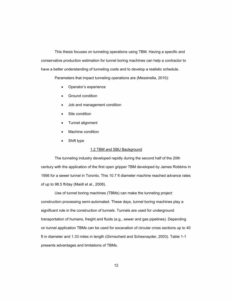
This thesis focuses on tunneling operations using TBM. Having a specific and
conservative production estimation for tunnel boring machines can help a contractor to
have a better understanding of tunneling costs and to develop a realistic schedule.
Parameters that impact tunneling operations are (Messinella, 2010):
Operator’s experience
Ground condition
Job and management condition
Site condition
Tunnel alignment
Machine condition
Shift type
1.2 TBM and SBU Background
The tunneling industry developed rapidly during the second half of the 20th
century with the application of the first open gripper TBM developed by James Robbins in
1956 for a sewer tunnel in Toronto. This 10.7 ft diameter machine reached advance rates
of up to 98.5 ft/day (Maidl et al., 2008).
Use of tunnel boring machines (TBMs) can make the tunneling project
construction processing semi-automated. These days, tunnel boring machines play a
significant role in the construction of tunnels. Tunnels are used for underground
transportation of humans, freight and fluids (e.g., sewer and gas pipelines). Depending
on tunnel application TBMs can be used for excavation of circular cross sections up to 40
ft in diameter and 1.33 miles in length (Girmscheid and Schexnayder, 2003). Table 1-1
presents advantages and limitations of TBMs.
13
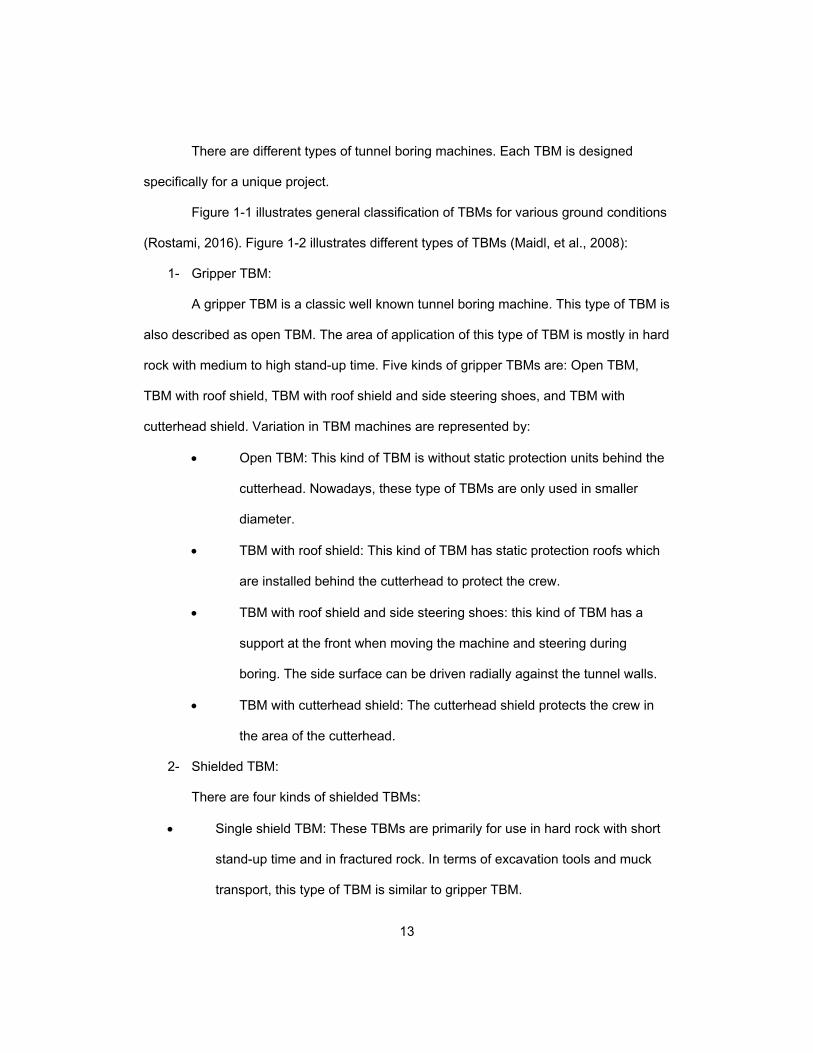
There are different types of tunnel boring machines. Each TBM is designed
specifically for a unique project.
Figure 1-1 illustrates general classification of TBMs for various ground conditions
(Rostami, 2016). Figure 1-2 illustrates different types of TBMs (Maidl, et al., 2008):
1- Gripper TBM:
A gripper TBM is a classic well known tunnel boring machine. This type of TBM is
also described as open TBM. The area of application of this type of TBM is mostly in hard
rock with medium to high stand-up time. Five kinds of gripper TBMs are: Open TBM,
TBM with roof shield, TBM with roof shield and side steering shoes, and TBM with
cutterhead shield. Variation in TBM machines are represented by:
Open TBM: This kind of TBM is without static protection units behind the
cutterhead. Nowadays, these type of TBMs are only used in smaller
diameter.
TBM with roof shield: This kind of TBM has static protection roofs which
are installed behind the cutterhead to protect the crew.
TBM with roof shield and side steering shoes: this kind of TBM has a
support at the front when moving the machine and steering during
boring. The side surface can be driven radially against the tunnel walls.
TBM with cutterhead shield: The cutterhead shield protects the crew in
the area of the cutterhead.
2- Shielded TBM:
There are four kinds of shielded TBMs:
Single shield TBM: These TBMs are primarily for use in hard rock with short
stand-up time and in fractured rock. In terms of excavation tools and muck
transport, this type of TBM is similar to gripper TBM.

14
Double shield or telescopic shield TBM: This TBM has front shield and
gripper or main shield which all are connected with each other with telescopic
jacks.
Closed systems: These systems are used under the water table for hard rock
and also fractured rock.
Micro machines: These machines are also equipped for use in hard rock.
The small boring unit (SBU) is a small diameter cutterhead and thrust bearing
assembly which joints to the front of the casing. It can proficiently cut hard ground with a
UCS greater than 4,000 psi (Long, 2006) and has been used to cut rock exceeding
25,000 psi. The SBU extends the capabilities of the horizontal auger boring (HAB)
machine for easier and faster boring through hard ground in installations ranging from 24
to 78 in. in diameter (Veidmark and Sivesin, 2009). The typical setup is similar to the
typical auger boring setup, except with a different boring head.
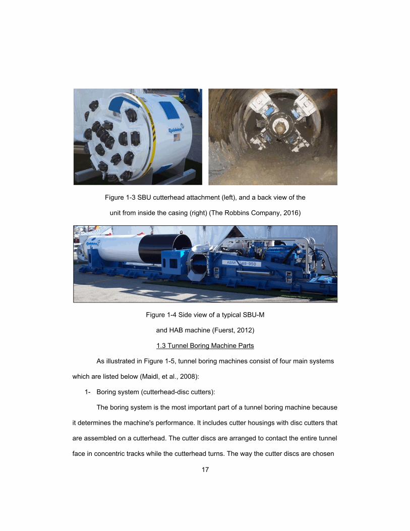
There are three types of SBUs that have been improved over the years: the
original small boring unit–auger (SBU-A), the motorized small boring unit (SBU-M), and
the small boring unit rockhead (SBU-RH):
1. Small boring unit-auger (SBU-A): This was the first SBU to be presented
and it can be used with any traditional HAB machine from 24 to 72 in. in
diameter. Figure 1-3 illustrates an SBU-A cutterhead attachment fitted
with single disc cutters. The image to the right shows the backside of the
SBU-A, which has a centrally placed hex shaft that connects to the full-
face auger. The SBU-A shield generally is welded to the front of the 24 to
72 in. steel casing pipe, within which the auger drives (Fuerst, 2012).
2. Motorized SBU (SBU-M): The SBU-M can be used for installations
ranging from 48 to 78 in. It affords personnel entry and longer drives than

15
the SBU-A does, and it is more precise because of the laser-guided
system and the jointed front shield, which enable steering. The
cutterhead is driven directly by an electric or hydraulic motor (Fuerst,
2012). Figure 1-4 illustrates a typical SBU-M and HAB machine that is
used to provide the thrust and remove the spoils.
Figure 1-1 General classification of TBMs for
various ground conditions (Rostami, 2016)
16
Figure 1-2 Different types of TBMs
(Adapted from Maidl, et al., 2008)
Table 1-1 TBM advantages and limitations
(Adapted from Farrokh, 2013)
Advantages Limitations
Better advance rate than other methods
of tunnel excavation
More geological data and parameters
needed to be provided
Excavation profile is more specific due to
having a constant section Massive money investment
Work is semi-automatic Machine designing and manufacturing is
time consuming
Lesser crew needed than other methods
of tunnel excavation
The tunnel profile section is constant
(circular section)
Work condition is safer than other
methods of tunnel excavation No instant curve driving1
Specific planning is required
1 Instant curve driving is ability of a TBM to make sharp turns
17
Figure 1-3 SBU cutterhead attachment (left), and a back view of the
unit from inside the casing (right) (The Robbins Company, 2016)
Figure 1-4 Side view of a typical SBU-M
and HAB machine (Fuerst, 2012)
1.3 Tunnel Boring Machine Parts
As illustrated in Figure 1-5, tunnel boring machines consist of four main systems
which are listed below (Maidl, et al., 2008):
1- Boring system (cutterhead-disc cutters):
The boring system is the most important part of a tunnel boring machine because
it determines the machine's performance. It includes cutter housings with disc cutters that
are assembled on a cutterhead. The cutter discs are arranged to contact the entire tunnel
face in concentric tracks while the cutterhead turns. The way the cutter discs are chosen

18
depends on the hardness of the ground. The selected disc determines the size of the
excavated rocks. The discs get pushed by the cutterhead rotation against the face of the
tunnel section and the discs make a slicing movement across the face of the tunnel. The
rock grinding occurs when the compressive strength of the rock is less than the cutter
disc’s compressive strength (Maidl, et al., 2008).
Laser and theodolite systems are for direction measurement. Theodolite is the
traditional survey instrument. A Laser system is usually installed beneath the crown of
tunnel, and it allows any direction variation to be detected immediately. However,
because adjustments are not necessarily automatic, an experienced crew is required to
make proper adjustments (Najafi, 2013).
2- Thrust and clamping system (thrust cylinders-gripper shoes-invert shoe/front
support-rear support):
The thrust and clamping system in TBM affects the performance of the tunnel
boring machine. It is in charge of the advance thrust and the boring progress. The
hydraulic cylinders produce the required pressure to forward right to the cutterhead
(Maidl, et al., 2008). Thrust system in TBM consists of a set of sidewalks grippers which
are forced out into the surrounding rock or tunnel liner support, using hydraulic cylinders,
to hold the TBM in place, furthermore, when the grippers are implemented in the place,
another set of hydraulic cylinders will cause the tunnel boring machine to push forward
through the tunnel face. “The term gripper describes the curved shoes, which are
matched to the excavated section and lie against the tunnel wall in the braced condition.
The gripper tunnel boring machine is stabilized during this process by the clamping at the
back and the shield surfaces around the cutterhead, which are pushed radially against
the tunnel wall” (Maidl, et al., 2008).

19
“During the moving operation, the grippers are loosened by hydraulic cylinders
and braced again with the necessary pressure against the tunnel walls in the new
machine position. This requires a free tunnel wall, which is only available in stable rock.
For shield TBMs, it is not the rock strength but the segmental lining, which is decisive,
because these machines cannot be braced radially against the tunnel walls but axially
against the lining. Between these two variants there are combined system solutions”
(Maidl, et al., 2008).
Behind the thrust system, there are some other important parts of tunnel boring
machine like trailing gear that includes hydraulic motors and transformers as well as
electrical boxes and dust control systems. The Backup system which is also known as
gantries, holds the conveyor system along with hoses, cables, utilities and also cords
(Jencopale, 2013).
3- Muck removal system (buckets-conveyor)
While cutterhead is working and excavating in TBM, the muck is collected by the
cutter buckets constructed as an empty slot around the perimeter of the
cutterhead, which is finally delivered to the conveyor belt. The system must be
powerful enough to transfer the muck without having problem. After the cutter
buckets, the tunnel boring machine muck removal system should have a good
support system providing transportation through soils and rocks. Either a
conveyor system or a rail system is suitable according to local conditions.
Sometimes having large dump trucks are also beneficial. However, “Problems
can arise, both with the cutterhead buckets as with the continuous conveyor,
through blockages caused by larger blocks of stone or the accumulation of fine-
grained but also cohesive muck” (Maidl, et al., 2008).

20
4- Support system (front support-roof shield):
The support system in TBM consists of front support and roof shield. The main
function of support system in TBM is to protect equipment and crew that are
working inside TBM (Maidl, et al., 2008). Also, the excavated tunnel should be
supported by some methods in order to prevent collapsing in roof and wall area
of the tunnel. Hence, as illustrated in Figure 1-6, there are five basic supports to
stabilize an excavated tunnel (Farrokh, 2013):
Rock bolt and shotcrete: this method is combination of rock bolts
and pumping concrete at the roof and wall area of tunnel.
Pattern of rock bolts: this method has systematic pattern of
implemented rock bolts.
Canopy: this method consists of rock bolt, channel, wire mesh,
and strap.
Steel ring: this method has systematic pattern of steel rings.
Segment: this method has systematic installation of segmental
lining.
“In case where short fault zones occur, ground improvement, e.g., by injection or
even freezing, must be carried out and for longer sections, the entire tunneling concept
will have to be altered to take the problem into account. Constant adaptation is not
possible” (Maidl, et al., 2008). Figure 1-7 illustrates a schematic operation of TBM under
the water level when ground freezing method is used for ground improvement of short
fault zones occurrence.

21
Figure 1-5 System group of a tunnel boring machine: 1- Boring system,
2- Thrust and clamping system, 3- Muck removal system,
4- Support system (Maid, et al., 2008)
Figure 1-6 Basic supports to stabilize
an excavated tunnel (Farrokh, 2013)

22
Figure 1-7 Schematic operation of TBM under the
water level with ground freezing
1.4 Factors Which Influence Tunneling Advance Rate in Hard Ground
As illustrated in Figure 1-8, many factors can influence a tunneling operation. It is
important to be ready to meet obstacles of tunneling in hard ground. These are listed as
below (Maidl, et al., 2008):
1- Ground--Includes ground type, mineral composition, strength, compression
shear, tension and splitting, tension strength, anisotropy, bedding to boring
axis, clearage to boring axis, jointing, and presence of formation water.
These factors have a significant impact on some parameters of
measurement like penetration, abrasion, muck composition, muck grading,
and time requirement for support.
2- TBM--Includes diameter, torque, thrust, disc type, Spacing of disc tracks
buckets, and equipment for installation of support. These factors have
significant impacts on penetration, tunnel face stability, chip size, and time
required for support.

23
Figure 1-8 Factors influencing tunneling advance for hard ground
1.5 Face Pressure
The face pressure is dependent on the machine torque. Additionally, the face
stability pressure depends on depth, hydro geotechnical and geotechnical conditions of
the project (Najafi, 2013).
“More sophisticated TBM systems incorporate a pressure chamber, which
provides a balance between the soil face pressure with the external water head and the
mixed soil pressure inside the chamber” (Najafi, 2013).

24
“Face pressure should be greater than the active earth pressure (Pa) of soil to
prevent subsidence at the ground surface and should be less than the passive earth
pressure (Pp) of soil to prevent heaving. The optimum value for the face resistance is in
the range of the earth pressure at rest P0” (Najafi, 2013).
Figure 1-9 illustrates face pressure distribution in no water and groundwater
conditions (Najafi, 2013). This figure illustrates that in case of having water in front of
cutterhead, there is an additional water pressure which the TBM should overcome for
excavation.
Figure 1-9 Face pressure distribution: (left) no
water and (right) groundwater (Najafi, 2013)
1.6 TBM Performance
Having performance efficiency in TBM has a significant effect on budget and
scheduling of a company. Having an unproductive tunnel boring machine due to poor
performance can lead a company which is working on a tunnel project to huge
bankruptcy. Tunnel boring machine performance is a function of several parameters
which are listed below (Advance Technology Consultants, 2015):

25
1- Time (shift time, mining time, downtime): Time is the number of working
hours in the project.
2- Penetration rate: Amount of excavation in linear length per unit of time.
3- Utilization factor: Percentage of the time which boring occurs in a specified
shift time.
4- Advance rate: Mined distance in a specific shift time.
Researchers and organizations have been working on tunnel boring machines for
the past 40 years in order to introduce new methods and models for tunnel boring
machine performance. Table 1-2 presents a review of some TBM performance prediction
models (Delisio et al., 2012). Table 1-1 shows that ground uniaxial compressive strength
(UCS) is one of the common parameters of hard ground factors needed to introduce a
prediction model for estimation of advance rate or penetration rate.

26
Table 1-2 Review of some TBM performance Prediction Models
(Adapted from Delisio, et al., 2012)
Prediction value Reference Ground factors
Penetration rate Graham (1976) Uniaxial compressive strength
Penetration rate Farmer and
Glossop (1980) Tensile strength
Penetration rate
Büchi (1984)
Compressive and tensile strength
Advance rate
Some TBM
parameters
Correction factors for anisotropy, joint spacing, mica content
Penetration rate Hughes (1986) Uniaxial compressive strength
Penetration rate CSM model
(Rostami and
Ozdemir, 1993)
Uniaxial compressive strength
Advance rate Tensile strength
Penetration rate Gehring (1995) Uniaxial compressive strength, correction factors for joints,
specific fracture energy
Penetration rate NTH (Bruland,
1998)
Uniaxial compressive strength, drilling rate index (DRI),
number of joint sets, porosity Advance rate
Penetration rate QTBM (Barton,
2000)
Hard ground strength, cutter life index (CLI), quartz content,
porosity Advance rate
Penetration rate RME (Bieniawski
von Preinl et al.,
2006)
Uniaxial compressive strength, abrasivity, hard ground jointing
at the face, stand-up time, water flows Advance rate
Specific energy
Bore-ability Index
(BI)
Gong and Zhao
(2009)
Compressive strength, volumetric joint count, brittleness index,
angle between main discontinuities and tunnel axis
Field Penetration
Index FPI
Hassanpour et
al.,(2009) Uniaxial compressive strength and RQD
Besides methods for determining tunnel boring machine performance, the
performance of tunnel boring machine can be affected by experience of the operator and
generally the contractor and their crews. Inaccuracies in estimating tunnel boring
machine performance can cause dramatic project delays (Farrokh, 2013).

27
1.7 Scheduling a Tunneling Project
Time is so important in tunneling projects. Time has a significant or dramatic
impact on cost of a project. A project should be completed within its specified deadline;
otherwise, it may have unfavorable consequences for contractors, including liquidation
damages. It is common to hear a contractor say, “You can win a little, or lose a lot,” and
“they bet their shop on this one.” These statements mean if a job goes bad, especially in
terms of project completion time, it may have disastrous impacts on financial well-being
of the contracting company (Najafi, 2013). Constructability and successful scheduling
almost always mean the difference between profits and losses. A contractor is motivated
to be creative in means and methods because it is the only way the firm can survive in a
highly competitive environment” (Najafi, 2013).
1.8 Functions of a Typical Tunnel Boring Machine
Functions of a typical tunnel boring machine are summarized below (Farrokh,
2013):
1- A thrust force is applied on the cutterhead and disc cutters.
2- The cutters penetrate into the face of rock and make the rock start cracking
and rock and gradually rock chips are created.
3- Rotation of cutterhead makes the rock chips to get looser allowing them to
get into the peripheral buckets of the cutterhead.
4- Rock chips must then be transported to the cutterhead hopper and then to
the conveyor belt.
5- The muck must then be transferred via a tunnel muck transportation system
(conveyor belt or railway).
6- Unloading of transported muck occurs at the tunnel portal.

28
When the last segment is installed, the hydraulic cylinders push against linings to
move forward. The double shield tunnel boring machine (TBM) combines benefits of both
the open tunnel boring machine and the single shield tunnel boring machine (Farrokh,
2013).
TBM begins the excavation and spoil removal process. Excavation, spoil
removal, and forward advancement continues until the segments are installed (Najafi and
Gokhale, 2005).
The factors that affect TBM productivity are (Salem, et al., 2004):
Cutterhead
Type of TBM and equipment
Crew and operator experience
Soil conditions
Drive length
Diameter of borehole
Ground water conditions
Obstruction or unusual soil conditions
Restriction to working hours
All these factors affect each other and are interconnected (Salem, et al., 2004).

29
1.9 Soil and Rock Groups
Soil conditions will greatly affect the tunneling or boring operations due to its
influence on productivity of the equipment (Najafi, 2013). The type of tunnel excavation
method needed, as well as the selection of cutterhead and tunnel boring machine (TBM)
will be dependent on ground condition.
Generally, ground with uniaxial compressive strength values greater than 7,250
psi are referred as hard rocks and commonly, rocks with uniaxial compressive strength
values less than 2,900 psi (especially less than 1,450 psi) are referred as soft rocks (NZ
Geotechnical Society INC, 2005).
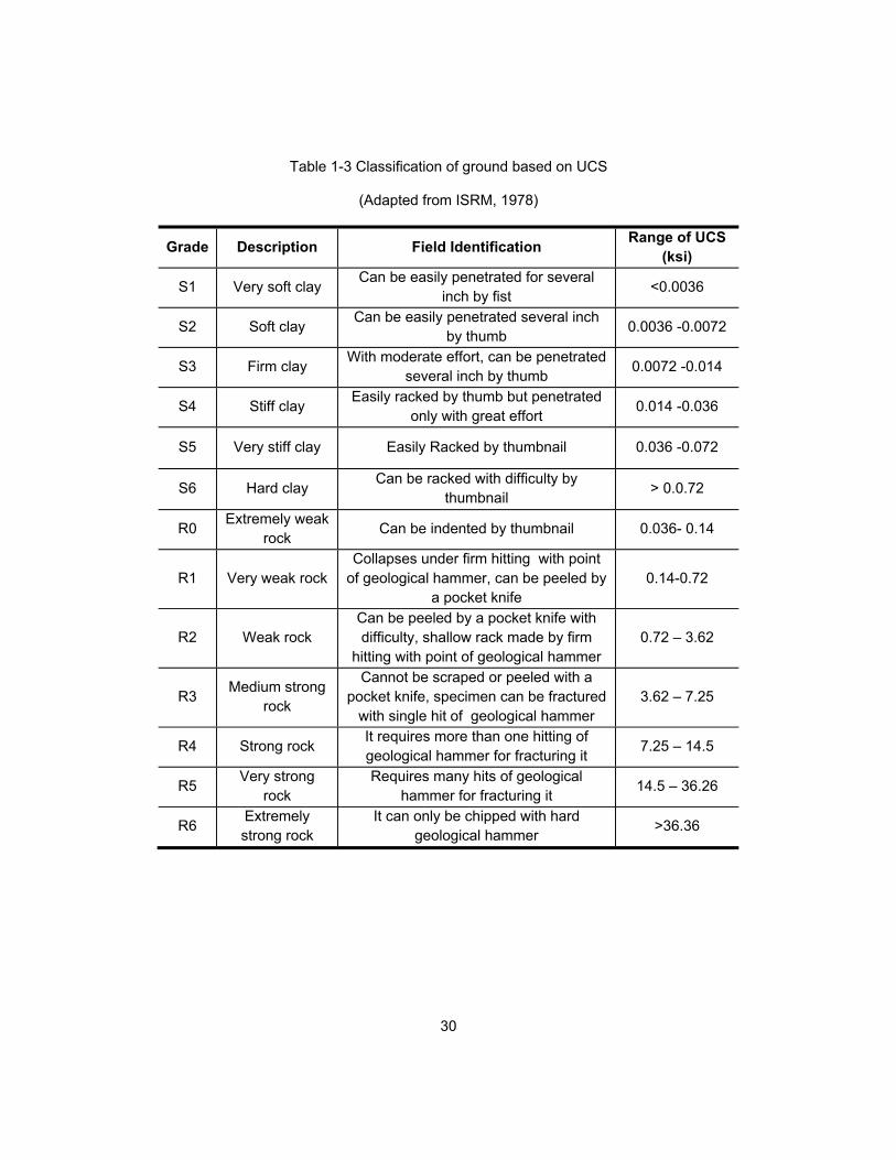
For engineering purposes, soil and rock are classified based on their field
identification and approximate range of uniaxial compressive strength in Table 1-3
(ISRM, 1978). Table 1-3 presents some field descriptions, which allows the contractor to
estimate the range of UCS of the project ground.
“The type of tunnel excavation method as well as cutterhead and tunnel boring
machine (TBM) selection will depend on soil or rock conditions” (Najafi, 2013).
30
Table 1-3 Classification of ground based on UCS
(Adapted from ISRM, 1978)
Grade Description Field Identification Range of UCS
(ksi)
S1 Very soft clay Can be easily penetrated for several
inch by fist <0.0036
S2 Soft clay Can be easily penetrated several inch
by thumb 0.0036 -0.0072
S3 Firm clay With moderate effort, can be penetrated
several inch by thumb 0.0072 -0.014
S4 Stiff clay Easily racked by thumb but penetrated
only with great effort 0.014 -0.036
S5 Very stiff clay Easily Racked by thumbnail 0.036 -0.072
S6 Hard clay Can be racked with difficulty by
thumbnail > 0.0.72
R0 Extremely weak
rock Can be indented by thumbnail 0.036- 0.14
R1 Very weak rock Collapses under firm hitting with point
of geological hammer, can be peeled by a pocket knife
0.14-0.72
R2 Weak rock Can be peeled by a pocket knife with difficulty, shallow rack made by firm
hitting with point of geological hammer 0.72 – 3.62
R3 Medium strong
rock
Cannot be scraped or peeled with a pocket knife, specimen can be fractured
with single hit of geological hammer 3.62 – 7.25
R4 Strong rock It requires more than one hitting of geological hammer for fracturing it
7.25 – 14.5
R5 Very strong
rock Requires many hits of geological
hammer for fracturing it 14.5 – 36.26
R6 Extremely strong rock
It can only be chipped with hard geological hammer
>36.36

31
1.10 Objectives
The objectives of this thesis are:
To evaluate and compare productivity of tunneling projects in different
ground and project conditions.
To consider impacts of geological conditions and tunnel diameter on
advance rate.
1.11 Need Statement
Although much research has been done on tunnel projects, an abundance of
tunnel projects remain which need analysis and review to give planners and underground
tunnel managers more information about different aspects of projects. One of the
significant aspects of a tunneling project is productivity of the tunnel boring machine
which is called the “advance rate.” Hence, it is important to compare different tunneling
projects in order to evaluate and compare productivity and geological impacts.
1.12 Expected Results
After reviewing and collecting data from reports of completed projects, it might be
possible to evaluate and discuss the results to see how different parameters of TBM and
different projects can affect productivity of tunnel boring machines.
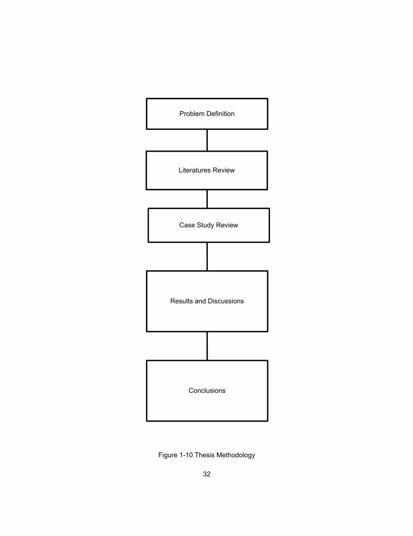
1.13 Methodology
Figure 1-10 illustrates the methodology, which is used for this thesis. The first problem is
to evaluate productivity of different case studies. Some literature reviews herein will
clarify some points about the advance rate of tunnel boring machines. Several case
studies were reviewed to collect the required data. Then evaluations of the collected data
will be presented as results and discussion.
32
Figure 1-10 Thesis Methodology
Problem Definition
Results and Discussions
Conclusions
Literatures Review
Case Study Review

33
1.14 Chapter Summary
Chapter one provided an introduction concerning the importance of tunneling projects
and background information about TBMs. Objectives, need statement, and expected
results were explained. Methodology was explained and illustrated. In this chapter,
impacts of project scheduling were explained. Also, performance and functions of a
tunnel boring machine were described. Soil and rock groups based on uniaxial
compressive strengths and field descriptions were discussed.
34
Chapter 2
Literature Review
2.1 Introduction
Chapter one presented an introduction and background, objectives, and brief
methodology for this research. In this chapter, several sources of literature are used to
provide more information about productivity, regarding the knowledge of TBMs and
tunneling. Lessons learned from literature have helped improve construction productivity
of tunnel operations.
2.2 Analysis and Prediction of TBM Performance
2.2.1 TBM Selection
Girmscheid and Schnexnayder (2003) described about background of TBMs. It
provided a look at different TBM configuration options as well as the explanations for
choosing a particular configuration. They discussed factors affecting the selection of
distinct tunnel boring machines. Their report gave a description of the importance and
functionality of the components of a TBM, including the cutterhead, gripper system, thrust
components, and the backup system. Furthermore, they provided information on mucking
and the conveyor systems, which focused on the muck car-rail method. Their
informational article did not perform an analysis or study. Therefore, it did not provide
conclusions or results.
2.2.2 Performance of New TBM Versus Refurbished TBM
Rostami (2011) performed a study prior to the start and during the bidding of the
Jollyville water transmission main WTP4 tunnel project. He investigated in depth the
options of using a new Robbins TBM versus using a refurbished TBM. His report involved
looking at the utilization rates of both options as well as the maximum daily rate of boring.

35
Rostami (2011) discussed the overall project as well as the tunnel reaches to its
end. Ground conditions for the Jollyville transmission main WTP4 project were
determined, and he used that data to perform a study on the TBM performance factors.
He analyzed and estimated the rates of production. After performing his study, he gave
solutions for improving productivity, such as the use of a continuous conveyor or
monitoring ground conditions of the tunnel closely to avoid delays in project. One of his
additional suggestions was to purchase and use a new TBM, so the purchase would be
an investment because the TBM can be used for future projects.
2.2.3 Influential Parameters in TBM Performance
Laughton (1998) described the basic operating features of tunnel boring
machines and recognized factors that influenced their productivity. He used a database
to predict excavation rates based on performance, machine, and rock masses. He
studied other subjects involved in tunneling such as rock mass behavior and cutterhead
penetration, but the main focus was on TBMs. He aimed at providing a method for
quantifying the risks involved with tunnel excavation based on the context of the project
plan. He discussed various muck removal options and also recognized problems
regarding the lack of data for TBM penetration rates and productivity.
Tarkoy (2009) presented the factors involved in maintaining performance of
TBMs. He discussed ways of estimating TBM advance rates and utilization factors. He
mentioned that the estimated utilization rate was often overlooked and could be a main
parameter with the greatest effect. He further discussed the other parameters involved in
TBM performance, such as project conditions, management, site limitations, TBM
downtime, and the labor work force. He pointed out that many of the variables are based
on human elements, and are, therefore, difficult to predict. He concluded that excavation
rates will typically vary from predicted rates by +/- 5%, and utilization rates will vary +/-

36
20% from parameters based on experience, calculated cycle times, and professional
judgment. Hence, the utilization factor will have significant impact on the daily advance
rates of a TBM.
2.2.4 Predicting Productivity
Abd Al-Jalil (1998) focused on maximizing the performance of TBMs and
precisely predicting the performance prior to the tunnel project. He completed a
breakdown analysis of the mechanisms of a tunnel boring machine as well as the
production process of typical tunnel excavation projects. He aimed to completely
understand the variability in the time and costs needed to complete a tunnel by
considering four main factors: 1) reliability and characteristics of the TBM and back-up
system, 2) variations along the tunnel, 3) geologic conditions and 4) the comprehensive
quality of management. One main contribution of this study was the compilation of 12
tunneling projects and the formation of a database so that construction simulation
programs could be developed and validated. He concluded that overall TBM performance
relies directly on machine failures and the time required to make necessary repairs.
Rahm, et al. (2012) aimed at predicting the disturbances in tunnel excavation
production by using TBMs. They reported that a lot of time was lost due to unknown
machine component failures, geological conditions, and inefficient production methods.
They presented two combined simulation methods involving the advancement rates of
TBMs and allowing for disturbances to be easily noticed. They implemented a case study
using the simulation method to demonstrate the functionality of the process. Their case
study comparisons revealed the significant influence of technical failures on TBM
performance.
Predicting productivity is the key for success in tunneling projects. Hegab et al.
(2006) proposed statistical models that represent the soil penetration rate of micro-

37
tunneling machines with collected information from 35 micro-tunneling projects. The
chosen model parameters included shear force of the cutterhead, jacking length, jacking
force diameter, and the driving (tunneling) time through distinct soils. Penetration time of
micro-tunneling project can be precisely estimated from the improved mathematical
models, that can help contractors to estimate the duration of a micro-tunneling drive.
2.3 Geological Condition in Tunneling Projects
2.3.1 Geological Uncertainty
Uncertainty of geological condition is one of chief factors in underground
construction and often inflating project costs. Many researchers have conducted studies
in order to model the geological conditions using many concepts such as statistical
techniques, and simulation. Ioannou (1987, 1988a, 1988b) presented a vast study to
decrease uncertainty in underground construction and focused on tunneling with TBMs.
As part of his study, Ioannou (1987) presented a general model for the probabilistic
prediction of tunnel geology with a set of geological factors like rock type, joint density,
and degree of weathering.
Site investigation can reduce geological uncertainty and thus decrease costs by
reducing the contingency amounts included in bids. Ioannou (1988a) presented research
results which provide a better explanation of how subsurface exploration and improved
contractual risk sharing can reduce the cost of underground projects. He defined the
major problems as methodology used by tunneling contractors to predict geological
profiles given a set of available geologic information, the geologic classification methods
used to connect the expected profile with acceptable construction options, and the 3-D
prediction of ground classes. He pointed out that different excavation and support
techniques will be necessary.

38
Ioannou (1989) presented a decision support system for the analysis of
geological exploration programs in underground construction such as tunneling with
TBMs to measure the economic value of different subsurface investigation options and to
provide owners and designers with a uniform and strict basis for making associated
technical and financial decisions. He described the methodology for using simulation to
achieve an estimate of the expected value and the standard deviation of the value of
sampled geologic data.
2.3.2 Site Investigation and Inspection
Geotechnical design requires the interpretation of ground conditions from site
investigation information. As an approach of a computer system to produce an
interpretation of the ground conditions, Toll (1995) described a knowledge-based system
to assist a geotechnical specialist with the processing of raw site investigation data to
arrive at interpreted design parameters and a model of the ground condition.
Oliphant et al. (1996) described the operation of a knowledge-based system
(KBS) to improve the inadequate site investigation practice. The developed system called
ASSIST (Advisory System for Site Investigation) comprising three linked sub-systems of
preliminary site investigation, data acquisition, and main site investigation was presented
in this paper.
Ioannou (1988b) presented the contractor’s point of view regarding the
usefulness of excavating a pilot tunnel as part of the site investigation program to show
guidelines for understanding its benefits. This research revealed that pilot tunnels are
generally useful in large projects with limited surface access with unfavorable geological
conditions. He commented that the construction of a pilot tunnel can decrease bid
contingencies up to 20% of the project cost.

39
2.4 Management and Decision Making
2.4.1 Decision Making
Optimal decisions for tunneling plans should be made in order to decrease time
and cost while referring to important factors such as geologic uncertainty and variability,
uncertainty in tunneling productivity, and contractor’s risk sensitivity. Likhitruangsilp and
Ioannou (2004) presented a computerized risk-sensitive decision support system
measuring and incorporating all main tunneling risks. The system can be applied to
determine dynamic optimal tunneling plans and risk-adjusted costs as parts of a
contractor’s risk sensitivity.
He and Wu (2007) emphasized the necessity of choosing and designing the
proper TBM for the desired project. They studied main features and parameters of rock
TBMs as well as engineering information of completed tunnels. They analyzed the
economic efficiency and overall productivity of the TBM by estimating and evaluating the
time and cost associated. Afterwards, they created a computer based decision support
system (DSS). This DSS was was used by designers of TBMs to fulfill the TBM type
selection during the stages of design and helped them match the proper TBM to the most
appropriate tunnel construction.
2.4.2 Management
Abdallah (2005) explored the use of exploratory tunnels as a project
management tool for estimating the cost and required time of tunnel construction. Based
on data collected from the Kaponig 1.7-mile exploratory tunnel, a section of a high-speed
double-track railway development in Austria, the risks related to design details for the
final tunnel extension were evaluated. A deterministic model based on Monte-Carlo
simulation was performed to predict potential results of the total project in terms of cost
and time and their related probabilities.

40
2.26 Chapter Summary
Some examples of past research on tunneling productivity are provided in this
chapter. Some authors focused on effective factors for increasing productivity of the
tunnel construction. These sources emphasized the differences in each tunnel and how
project, machine, and site factors can determine means and methods. Geologic
composition or formations and uncertainty of ground conditions are the main issues in
tunneling productivity.

41
Chapter 3
Case Study Evaluation2
3.1 Introduction
Chapter two presented several literature reviews on productivity, geological
formations, and management of tunneling projects. This chapter will describe different
case studies regarding completed tunneling projects by tunnel boring machines from
small diameter to large diameter.
3.2 La Réunion Irrigation Project
The La Réunion irrigation project is located in a French territory in the Indian
Ocean. The project consists of a system of tunnels that irrigates sugar cane crops and
delivers water to the people on the island’s west side. Some organizations funded the
project, including the French government, the European community, the Réunion
department and the Réunion region.
The project was given to Robbins in 1990. The company built a 14.1 ft diameter
single shield tunnel boring machine (TBM) for the boring of two tunnels. These tunnels
carry the combined inflow of water from other tunnels and river water from the Rivière de
Galets. This water is then transported 5.3 miles to the western side of the island. The
second tunnel is a short 1.5 miles tunnel which carries the water from the first tunnel via
siphon under the Rivière de Galets.
Geological formations in all La Réunion tunnels were made of olivine basalt and
in some parts blocky rock combined with mudstone and clay with the UCS of 7,251 to
21,460 psi.
2 The data for case studies are from Robbins Company (The Robbins Company, 2016).

42
Robbins designed the single shield TBM to meet the unique challenges of
abrasive rock and water inflows in two tunnels. The machine’s cutterhead was enhanced
with 17 in. disc cutters mounted for safe changing from the rear. Robbins also added a
pumping system to the TBM and seals to the cutterhead and shield, so, with these added
features the machine was prepared for boring through basalt with heavy water inflows.
Despite many difficult geologic conditions, the TBM continued to make
significant advances and finished on schedule. The machine advanced at an average
rate of 14.6 ft per hour or 56 ft per day. An average workweek consisted of five days in
three shifts. The second tunnel started excavation in 1993 and finished in six months.
3.3 Alimineti Madhava Reddy (AMR) Project
Alimineti Madhava Reddy (AMR) project was a 27 mile tunnel without
intermediate access to above ground help. The tunnel transfers floodwater from the
Krishna river to dry regions of India’s Andhra Pradesh state, providing irrigation to
400,000 acres of farmland and clean drinking water to 516 villages.
Contractor Jaiprakash Associates Ltd. (JAL) won the $413-million engineer-
procure-construct contract in 2005 from the government of Andhra Pradesh to construct a
head regulator and two tunnels, including the main 27 miles tunnel. On May 26, 2006,
JAL awarded a complete contract with the Robbins company for two 32.8 ft diameter
double shield tunnel boring machines, as well as conveyor systems, back-up systems,
spare parts, personnel, and technical support.
Ground conditions were made up of quartzite zones with a UCS of up to 65,000
psi. The zones were layered and divided by shale for around 50% of the length with
granite and a UCS of 23,000 to 28,000 psi for the remaining 50%. One modification about
the TBM was to design drive motors of the machine to run each machine at a higher than

43
normal speed for optimal penetration rates in the hard rock. By 2010, The machine had
excavated about 3.67 miles, with advances of up to 489 ft per week.
3.4 The Mill Creek II Sanitary Sewer Storage Tunnel
The Mill Creek II sanitary sewer storage tunnel was one of several tunnels
undertaken in Cleveland for wastewater management. The tunnel avoids sewer overflows
in the Cleveland regions that were due to increasing population.
The Mill Creek tunnels were split up into three separate contracts. In 1999,
project owner Northeast Ohio Regional Sewer District gave construction Contract II to a
joint venture called KMM&K, and Kassouf Co., Murray Hill Construction, Mole
Construction, and Kenny Construction. The contractors chose a 23.6 ft diameter Robbins
double shield TBM to excavate the 2.5 miles long tunnel.
The tunnel passes through cracked gray Chagrin shale, characteristic of the Ohio
area. The rock is fairly strong shale with a uniaxial compressive strength of 6,000 to
12,000 psi. Excavation began in April 2001 and the TBM faced few difficulties. The tunnel
boring machine was over halfway through the drive, by August of 2001. The machine
reached advance rates of up to 10 ft per hour and accomplished a best shift of 85 ft in 8.5
hours. By December 2001, the TBM finished the tunnel, well within its contract schedule
requirements..
3.5 The Yellow River Water Diversion Project
The Yellow River water diversion project is a large network of tunnels which
brings water to chronically dry zones of Shanxi province. The water system consists of
multiple tunnels totaling over 62 miles.
The Joint Venture (CMC, Impregilo, Chinese Water Conservancy and
Hydropower Engineering Bureau No. 4) was given Lots 2 and 3 in 1997. Cooperative
Muratori Cementisti Ravenna (CMC) of Italy was given the contract for Lot 5 in the year

44
2000. All of the contractors chose Robbins double shield TBMs to excavate through the
challenging geology.
Lot 2: The geology in Lot 2 consisted of limestone and dolomitic rock with
probability of occasional faults. Karst formations were also abundant. The uniaxial
compressive strength (UCS) of the rock was 6,000 to 20,000 psi.
Lot 3: The geological terrain here consisted of dolomitic limestone and mudstone
and Triassic sandstone with a UCS matching that of Lot 2.
Lot 5: The geological composition here was made up of sandstone, limestone,
and siltstone with occasional faults and a UCS of 4,000 to 30,000 psi.
The types of TBMs used in this project are described below:
Lot 2: Lot 2 used two Robbins double shield TBMs. The first tunnel boring
machine was a new Robbins TBM that bored two tunnels (T4 and T5) of 4.1 miles and
15.8 miles in length. The TBM had a 16.1 ft diameter cutterhead and 17 in. disc cutters.
For the second machine on Lot 2, Robbins also refurbished a 16.1 ft diameter
TBM for a 8.7 miles long tunnel (Tunnel T6). This TBM had 17 in. disc cutters.
Lot 3: another double shield TBM was used for a section of T7 in Lot 3 with 13.7
miles in length. The 15.7 ft diameter Robbins double shield TBM had 17 in. disc cutters.
A TBM made by NFM company bored the other half of the 25.3 miles long T7 tunnel.
Lot 5: for Lot 5, CMC utilized a 15.7 ft diameter Robbins TBM that had been kept
in China since 1994. The machine was completely refurbished by Robbins for the project.
CMC and Robbins decided to make the existing cutterhead better for improved reliability
in fractured geology. The machine had 17 in. disc cutters.
Excavation started at the same time on Lots 2 and 3 in February 1999. The T4
TBM excavated the 4.1 miles tunnel in just 8 months and experienced fairly few
problems. The used tunnel boring machine broke a world record in its size category with
45
a best month of 5,978 ft and reached to a best day of 326 ft. The same TBM excavated
the 15.8 miles long T5 tunnel beginning in November 1999 and ending in the year 2001.
The refurbished Robbins TBM began excavating the 8.7 miles long T6 tunnel in
December 1999. The TBM reached to daily advance rates of 266 ft, a best month of
4,511 ft, and an average monthly advance rate of 1,804 ft.
Boring the 13.7 miles section of tunnel T7 at Lot 3 started in February 1999 and
finished in April 2001. The Robbins TBM and the NFM machine started at opposite ends
of the tunnel and met in the middle. The Robbins tunnel boring machine managed to
achieve an average month of over 2,297 ft and had a best month of 4,203 ft.
Lot 5 excavation started as boring at Lots 2 and 3 finishing up in September
2000. By December 8th, the refurbished Robbins TBM had already set a best day of 118
ft and averaged over 3,281 ft in its first month boring. The TBM later set a world record
for its size category at 4,436 ft per month. The TBM bored through the 8.4 miles long
tunnel in September 2001.
3.6 Cobb County
The Chattahoochee Sewer tunnel is part of a project that meets increasing
wastewater capacity necessities in East Cobb County. The tunnel delivers flow
equalization to the RL Sutton Water Reclamation Facility and prevents potential
wastewater overflows due to the growing population in Cobb County.
In 2000, project owner Cobb County Water Systems gave the construction
contract to the Gilbert-Healy Joint Venture. The contractors chose two 18.3 ft diameter
Robbins TBMs to excavate a 9.1 miles long section of the 9.5 miles tunnel.
The geological composition of the Atlanta area is made up of medium grade
metamorphic rocks with some granitic rocks. Much of the rock contains gneiss, mica, and
schist with an uniaxial compressive strength (UCS) of 22,000 to 33,000 psi.

46
Robbins delivered one new and one renovated TBM for the tunnels. The new TBM for the
south tunnel had 19 in. disc cutters. The renovated TBM for the north tunnel was
completely redesigned for the project. This machine also included 19 in. disc cutters.
The TBM in the south tunnel started excavating at the Elizabeth Lane shaft near
the south end of the tunnel in August 2001 and completed excavation in October 2002.
The TBM faced few problems and advanced 2,133 ft in its first month of boring. The TBM
in the north tunnel started excavating in November 2001 and completed excavation in
December 2002.
3.7 East Side Access Project
New York City’s East Side Access project involved construction of a new subway
line required to relieve heavy traffic congestion between the areas of Queens and
Manhattan. The project, given to the Dragados Judlau JV, is located in a variety of
geology from soft ground to hard rock. The main geology was made up of schist, gneiss,
and granite with a UCS of 14,500 to 40,000 psi.
The Robbins TBM bored the Westbound running tunnels. The diameter was 22
ft. The Robbins tunnel boring machine completed four drives, totaling 3.3 miles beneath
Manhattan. The TBM first bored 1.5 miles in the direction of Grand Central Station, and
was then retracted 1.2 miles through the newly bored tunnel, leaving all tracks and tunnel
support structures in place. The machine bored three more tunnels at varying elevations.
Boring on the first tunnel with the length of 1.45 miles, started on September 30,
2008 with a total of 907 boring hours. The 0.33 mile tunnel ended on February 20, 2009
after 267 boring hours. A third 1.1 miles long tunnel was finished in February 2010. By
June 2010, the machine had accomplished its fourth and last 0.4 mile long drive after 281
boring hours.

47
3.8 Hong Kong Cable Tunnel
The 275 KV Cable Tunnel on Hong Kong island delivers a transmission line from
a power station adjacent to Lamma island. Electricity travels through the 3.3 mile long
tunnel via six 275 KV cables to increase power supply to people on the eastern side of
Hong Kong island.
The Hong Kong Electric Co., owner of the project, contracted Nishimatsu
Construction Co., to construct the tunnel, Nishimatsu selected a 15.8 ft diameter open
tunnel boring machine (TBM) for the project, the first ever TBM to excavate in Hong
Kong.
The geological terrain was made up of a granite and quartz mixture with some
volcanic rocks holding hard tuffs and lavas with a UCS of 23,206 to 29,000 psi. Hence,
Robbins enhanced the high-performance TBM with 32 19-in. disc cutters in order to
prevent any further problems due to geological conditions.
Boring on the 3.3 mile long tunnel started in March 1991. A section of the tunnel
on the Wong Nei Chung fault line led to some difficulties. Shattered and weathered
granites required rock support and advance probe drilling which decelerated the boring
process. The average advance rate of the TBM was 328 ft per week and its average rate
of penetration was 9.1 ft per hour.
3.9 Kárahnjúkar Hydropower Project
The Kárahnjúkar Hydropower Project created the Kárahnjúkar power plant which
delivers 4600 GWh of electricity yearly to a nearby aluminum smelting plant.
Project owner Landsvirkjun gave the construction contract for the hydroelectric
project to the Iceland branch of Impregilo S.p.A. The contractor gave the contract to
Robbins for three Robbins open high performance TBMs for excavation of three lengths
of tunnel.
48
The machines started excavating between April and September 2004 in basalt,
moberg, and pillow lava geology with a UCS of up to 44,000 psi.
By June 2006 the machines had made good advancement in main head-race
tunnels. First TBM completed its drive on September 9, 2006 after accomplishing
impressive advance rates with a best month of 2,755 ft in March 2006. On the same day,
second TBM achieved good advance rates with a best of excavating 302 ft in 24 hours.
Second TBM ended its initial drive in fall 2006 and was then disassembled and
transported to excavate an extra 5.4 miles long section of the Jökulsá diversion tunnel in
2007. The third TBM completed its main tunnel drive on December 5, 2006.
The Jökulsá diversion tunnel adds to the water supply capacity of the
powerhouse by connecting the Ufsarlón Reservoir to the main head-race tunnel. Work
started in April 2007 and was completed in April 2008. During the excavation of 5.4 mile
tunnel, the best advance rate was 348.2 ft in 24 hours. In August 2007, the machine
attained the feat again by excavating 380 ft in 24 hours and1,400 ft in one week. The
machine excavated at constantly high rates and finished its bore on schedule.
3.10 Little Calumet
The Little Calumet Leg tunnel was the final section in first phase of Chicago’s
long-running Tunnel and Reservoir Project (TARP). The project involved storm water
storage, reservoirs, and feeder tunnels that have significantly improved water quality in
Chicago-area Rivers. The Little Calumet Leg is part of a longer TARP tunnel scheme that
avoids combined sewer overflows from spilling into the Little Calumet River.
In 2002, the project owner, Metropolitan Water Reclamation District of Greater
Chicago (MWRDGC), gave the construction contract to the Jay Dee/Affholder Joint
Venture. The two contractors divided the work, with Jay Dee responsible for surface
works, shallow tunnels, and shafts. Affholder was responsible for deep tunnels and TBM

49
excavation. The joint venture chose a 18.2 ft diameter Robbins open TBM to excavate a
8.0 mile section of tunnel.
The rock was made up of Silurian age dolomitic limestone with a uniaxial
compressive strength (UCS) of 14,000 to 35,000 psi. The limestone had few faults and
was considered as a good tunneling ground condition. Robbins refurbished the open
TBM specifically for the project. The machine was enhanced with thirty-nine 19 in. disc
cutters.
Excavation of the tunnel started on February 13, 2003. The tunnel was driven in
two parts from a central launch shaft with an initial excavation of 3.8 miles. After the initial
drive, the head cutterhead support were pulled out of the reception shaft. The rest of the
machine was then reassembled with the head and cutterhead support and taken back
through the tunnel for the second 4.1 miles drive.
The machine finished both drives perfectly. The TBM had best advance rate in a
single 8-hour shift at 150.1 ft, the best advance rate in a day at 382.9 ft, and the best
advance rate in a week at 1,557 ft. The TBM finished excavation in February 2004.
3.11 Olmos Trans-Andean Tunnel
The Olmos Trans-Andean tunnel has been more than 100 years in the
construction, with several efforts made in the 1950s using drill and blast techniques. The
tunnel, more than 12 miles long in total, is part of a larger system to deliver water from
the Huancabamba River on the eastern side of the Andes to drought-ridden zones on the
Pacific Ocean watershed by a tunnel bored through the continental divide. The first part
included a 140 ft high dam diverting the Huancabamba River adjacent to the village of
San Felipe through the mountains to the dry Olmos river on the Pacific side. Now that the
first part of the tunnel project is operational, the system will provide more than 500 billion
gallons of water annually for the irrigation of 130,000 acres of farmland.

50
General contractor Concesionaria Trasvace Olmos, won a 20-year build-operate
concession from the Peruvian National Government and Lambayeque Regional
Government in the year 2004. The 17.4 ft Robbins TBM was launched for subcontractor
Odebrecht Peru Ingenieria y Construccion (OPIC) in March 2007. The TBM was
designed to excavate a 7.7 mile long tunnel through the Andes mountains beneath up to
6,500 ft of hard, potentially squeezing rock.
The machine bored through complex geological formations which were made up
of quartz porphyry, andesite, and tuff with a UCS from 8,700 to 32,600 psi. The TBM
advance rates was 2,211 ft per month. After four years of extreme excavation and harsh
geologic conditions, the TBM finished excavation on December 20, 2011.
3.12 Pahang Selangor Raw Water Tunnel
The Pahang Selangor Raw Water Tunnel, for the Malaysian Ministry of Energy,
Green Technology, and Water, conveys raw water from the Semantan River in Pahang to
the south Klang valley zone of Selangor state. The three tunnels have total lengths of
27.7 miles. The tunnel transfers 7,300 gallons of water per second to a new treatment
plant. The drinking water was supplied to about 7.2 million people by 2013.
The SNUI JV, consisting of Shimizu Corporation, Nishimatsu construction, UEM
builders Bhd, and IJM construction, selected three Robbins 17.2 ft diameter open TBMs
to excavate the three sections of the tunnel.
The geologic composition during the initial stages of advance consisted of hard,
abrasive granitic rock with a UCS of up to 29,000 psi. The first machine was provided on
November 10, 2010, followed shortly after by the second on December 30, 2010. The
third machine started boring in March 2011 and all three machines finished excavating as
scheduled.

51
During the initial phases of advance, the machines reached to rates of up to 11.5
ft per hour, leading the three machines to excavate over 4,600 ft, 1,800 ft, and 1,100 ft
monthly, respectively by April 2011. The cooperation of Robbins field service and joint
venture contractors, Shimizu Corporation, Nishimatsu construction, UEM builders, and
IJM construction (SNUI) allowed the TBMs to have strong advance rates of 1,560 ft on
average per month, and the best advance rate of 2.130 ft per month.
3.13 West Qinling Rail Tunnels
The West Qinling tunnels are part of the Chinese government’s Lanzhou to
Chongqing railway, a massive 500 mile long system that connects the capital of Gansu
province (Lanzhou) with southwestern Chongqing, a mega-city with population of 35
million. The parallel rail tunnels were used for freight transportation, and connected the
city of Longnan with the towns of Waina, Luotang and Fengxiang within Gansu province.
China Railways signed a contract with Robbins for the supply of twin 33.5 ft
diameter open tunnel boring machines In January 2009. The TBMs bored two 10.3 miles
tunnels through the Qinling mountains. Geological compositon in the two tunnels
consisted of sandstone and phyllite rock with a UCI of 4,300 to 11,600 psi beneath more
than 4,600 ft of cover.
The two TBMs, for contractor China Railways 18th Bureau Co., were assembled
at a local workshop and delivered to the jobsites. The first machine, for the left line, was
started at the end of June 2010 after being walked through a 1.2 miles long tunnel. The
second machine, for the Right line, was begun on July 17, 2010.
During spring 2011, the first open tunnel boring machine had an advance rate of
771 ft in one week and 2,761 ft in one month which rates much more than any ever
recorded for TBMs in the category of 32.8 to 36 ft diameter range. The project was
supposed to be done in 2014.

52
3.14 Center for Underground Infrastructure Research and Education
Researchers of Center for Underground Infrastructure Research and Education
(CUIRE) from University of Texas at Arlington (UTA) did some case study analyses
related to TBM productivity. Table 3-1 represents the analyzed case studies regarding
CUIRE research. Table 3-1 presents the productivity of all analyzed case studies, the
geology, tunnel length, location, contractor’s name, and diameter of TBM.
Table 3-1 CUIRE case study analysis report2
Project Contractor Location Tunnel Length
(mi)
Diameter (ft)
Geology TBM rate (ft/day)
Riyadh (Line5)
FAST Saudi Arabia
25 32.1 Limestone 100
Riyadh (Line1)
FAST Saudi Arabia
24.2 11.2 Limestone 50
The Riyadh (Line2)
FAST Saudi Arabia
15.5 11.2 Limestone 50
Green Line Metro Doha
PORR
Doha, Qatar 19 23.1 Limestone, Midra
110
Red Line Metro Doha
- Doha, Qatar 7.5 32.1
Limestone, Midra
115
Pyrenees Tunnel
HVDC
Pyrenees mountain, Spain
5.5 14.0
Granodiorite, schist, granitoid, gneiss and miocenic rock
75.5
Northeastern China
- China 9.3 28 Hard Rock 74
Decline Project
- Queensland, Australia
1.2 26.2 Hard Rock
82
2 Prepared by Ramtin Serajiantehrani, Ph.D. student at the Center for Underground
Infrastructure Research and Education (CUIRE), University of Texas at Arlington.

53
3.15 Shayler Run Segment C Sewer Replacement Project
The Clermont County Water Resources Department employed Indianapolis
contractor Midwest Mole for the $15-million project, and decided to use only one machine
for the seven tunnels. A 72 in. diameter Robbins double shield Rockhead was used to
bore all of the tunnels, with a total length of 9,513 ft.
Due to the project location which was below the creek bed, ground conditions were highly
diverse, made up of interbedded layers of limestone and shale that varied from dry to
sticky and wet. Two cutterheads were used for this project. One cutterhead was used for
excavation through mixed ground, and the other one was used for rock zones. The mixed
ground cutterhead was enhanced with 6.5 in. single disc cutters and carbide bits, while
the hard rock cutterhead featured 11.5 in. single cutters. The machine’s circular
cutterhead is capable of excavating ground with a UCS from 4,000 to over 25,000 psi.
A total of seven tunnel crossings linked by eight shafts were built by Midwest
Mole. The machine was able to achieve high production rates of 40 to 60 ft per 12-hour
shift. Boring of the initial 1,589 ft crossing started in May 2010 in mixed ground, and the
Rockhead broke through to its first shaft site in August. Then, machine began excavating
the second 1,888 ft crossing.
Crossings 3 and 4, with lengths of 1,056 ft and 1,000 ft, sequentially, were
excavated in December 2010 and January 2011 in adverse winter weather conditions
and production rates stayed high and both crossings were successfully excavated by
January 2011.
The Rockhead started its fifth and longest crossing of 2,014 ft in April 2011, and
achieved a world record in tunneling distance for a hard rock machine with its 72 in.
diameter. For crossings sixth and seventh, 1,320 ft and 646 ft, respectively, the mixed
ground cutterhead was replaced with a hard rock cutterhead. Due to negotiations with

54
local landowners and an alteration in shaft location, the final crossing started in January
2012 and finished one month later. The entire project reached completion in July 2012.
3.16 City of Clinton Contract B Force Main Project
The Iowa towns of Clinton, Camanche and Low Moor were recognized as
needing updated wastewater treatment systems. The towns all had over 10,000
residents, however, their water and sewer treatment plants were insufficient. In 2009, a
statewide recovery program called I-JOBS was created in Iowa, and a $20-million in
project funding was assigned for improving water quality. These funds were specified for
water treatment projects in the three towns.
The City of Clinton gave their share of the funding, $9.5-million, to general
contractor Merryman Excavation. Illinois-based L.J. Keefe Co. was selected as the sub-
contractor for the project. The contract, known as City of Clinton contract B Force Main,
requested six crossings below roadways and rivers, three of which required TBM
tunneling. The remaining three crossings required small boring units (SBUs). Two
Robbins SBU-As were selected for the 250 ft and 270 ft crossings, and a third Robbins
motorized SBU (SBU-M) was chosen for the 395 ft crossing.
The 250 ft and 270 ft crossings undercut the Mississippi river, and were
recognized as hard rock with UCS of over 10,000 psi. The longest crossing was
underneath heavy-traffic Highway 67, and testing of the area showed a mixed face of
sand, clay and hard rock with a UCS of 10,000 psi.
In November and December 2011, the 60 in. and 42 in. SBU-As, respectively,
were launched 30 to 35 ft beneath a branch of the Mississippi river. Both SBU-As finished
excavation on time. The first SBU finished boring on December 20, 2011, and its
counterpart did the same on February 10, 2012. Each machine achieved an average
advance rate of 20 ft per day. The 72 in. SBU-M was started excavating in January 2012

55
and achieved advance rates of 20 ft per day in clayey conditions and about 30 ft per day.
On February 14, 2012, the project was finished.
3.17 Tahoe Forest Hospital District Central Energy Plant Prep Project
The Tahoe Forest hospital is a growing healthcare center situated in Truckee,
California. In autumn 2010, they were in the process of designing a new cancer section
when it was determined that extra utility and mechanical lines were required before the
new building could be constructed. To house the bundled utilities, three crossings had to
be excavated directly below the active main hospital.
General contractor AM-X Construction & Excavation, Inc. subcontracted the
three parallel 70 ft parts to Silver State Boring Inc. Because of variable ground conditions
and hospital noise limitations, the contractor chose for a Robbins SBU-A with a mixed
ground cutterhead. The hospital is set on ground made of large granite boulders, and
Silver State was worried that one of these rocks would be hit during excavation. This
concern was actualized 25 ft into the first excavation when the SBU-A was trapped the
edge of a boulder about 12 ft in diameter.
During the second bore, the machine excavated straight through the same
boulder. Additional boulders with a UCS of 25,000 psi were faced during the third bore,
and the SBU-A successfully powered through them as well. The first of the three bores
started in October 2010, and by November 2010 all three bores were successfully done.
Advance rates for the project were approximately 10 ft per day.
3.18 Chester Boulevard Interceptor Sewer
The City of Richmond, Indiana is a developing community of 50,000 people. To
meet future projections, the city created a scheme to double the current capacity of its
sewer system via four mile long extension.

56
In December 2006, the Richmond Sanitary District gave a $4.7-million contract to
general contractor Brackney Inc. for building the Chester Boulevard interceptor sewer, a
two miles expansion of the new pipeline to deliver service to a commercial district and
nearby hospital. Then, Midwest Mole, Inc. was subcontracted by Brackney to bore four
hard rock crossings underneath a river and historic walking trails. Midwest Mole chose to
use a 48 in. diameter SBU-A for the two shortest bores of 180 ft and chose a 54 in.
diameter single shield Rockhead for the two longest bores of 400 ft each.
The geological composition of the project consists of shale and limestone rock
with a UCS of up to 10,200 psi. Midwest Mole decided on a Robbins Rockhead for the
longest excavation. The cutterhead on the 54 in. machine was featured with 6.5 in. single
disc cutters for optimal boring in solid rock. After boring over 3,900 ft, the machine was
sent in to the Robbins shop for its first repair and change of disc cutters.
Midwest Mole bored the first 400 ft long crossing in March 2007. The machine had
advance rates averaging 20 to 26 ft per 10-hour shift. The second crossing excavation
started in May 2007 with advance rates of up to 30 ft per shift.
3.19 Milford Haven Gas Connection Project
In one of the U.K.’s most extensive infrastructure developments, the Milford
Haven gas connection project stretched over 190 miles across South Wales. The pipeline
was built to provide liquefied natural gas (LNG) from a port at Milford Haven, delivering
up to 20% of the U.K.’s natural gas for owner National Grid.
The project was built in two phases and work started in early 2006. Both phases
were done in November 2007. Phase I was about 75 miles long and stretched from the
towns of Milford Haven to Aberdulais. Phase II of the project added another 115 mile
pipeline from Felindre to Tirley in Gloucestershire.

57
General Contractor NACAP Land & Marine built many of the crossings for both
Phases I and II, subcontracting some hard rock crossings to local contractor B&W
Tunneling Ltd. B&W used three 48 in. Robbins SBU-As and two 48 in. Robbins SBU-Ms
to bore 62 crossings varying from 65 to 260 ft in length.
The majority of crossings were placed in siltstone and mudstone rock with some
interbedded clay and gravel with a UCS of 10,000 to 29,000 psi.
B&W used two motorized SBUs, one for mixed ground and one for hard rock.
The mixed ground cutterhead was enhanced with 9.5 in. diameter single disc cutters. All
crossings were bored successfully and generally had an average from 5.0 to 6.5 ft per
hour.
3.20 Kota City Water Supply Project
After many unsuccessful attempts during eight years, just three hard rock
crossings remained on a necessary water supply line in Kota City, Rajasthan, India.
The eight mile pipeline, part of the government’s Rajasthan Urban Infrastructure
Development Plan (RUIDP), was designed to increase water supply and avoid water
pollution problems in the city. The completed scheme provides 6.3 million gallons of
water per day to about 70,000 people. Vichitra bought a 5 ft diameter Robbins small
boring unit (SBU-A) with 11.5 in. disc cutters. Much of the crossings was made of
quartzite rock with a UCS of 29,000 to 36,000 psi, and some tracts of soil and mud.
Three rail excavations were finished by autumn 2008 in abrasive, hard rock. The
crossings were bored in two 164 ft long passes from either side of the tracks with
advance rate of 5 ft per hour.
3.21 Glenwood Cable Tunnel
EIC Associates were contracted in 2006 to build eight miles of a 115 kV power
transmission line across Darien, Stamford, and Norwalk in Connecticut, USA. EIC used a

58
Robbins 60 in. double shield rockhead to bore two crossings beneath the Metro North
Railroad in Darien.
The geological composition of the project location was made up of highly
fractured meta-quartz monzonite with a UCS ranging from 5,000 to 20,000 psi. Boring
began in the spring of 2008. Crews worked six days a week in two 10-hour shifts. The
machine bored the two crossings averaging 10 to 25 in. per hour.
3.22 Locust Street Sanitary Improvements Project
In Tigard, Oregon, upwards of 1.1 miles of gravity sewer were implemented by
general contractor Northwest Earthmovers Inc. for project owner Clean Water Services.
The contract was awarded to Gonzales Boring & Tunneling to finish three crossings that
formed part of the Locust Street Sanitary Improvements project No. 6335. The three
crossings had lengths of 230 ft, 600 ft, and 320 ft.
Gonzales Boring & Tunneling purchased a Robbins a 42 in. SBU-A. Geological
terrain for the first crossing was made up of clay and basalt, while the second crossing
was composed of basalt at various rock strengths ranging from 7,000 to 12,000 psi. The
SBU cutterhead for the crossings was featured with 6.5 in. single disc cutters. The
advance rates of the machine were 40 ft per 10-hour shift.
3.23 North Carolina Project
This project, owned by Charlotte Mecklenburg Utilities (CMU), needed to provide
15 miles of pipeline in south of Charlotte. Pipeline diameters ranged from 36 to 64 in. and
created more water capacity to meet higher consumer demands in the region.
Horizontal Unlimited Inc. was contracted particularly for a short 118 ft part of
pipeline through hard rock. In the year 2001, Horizontal Unlimited Inc. purchased a
Robbins 66 in. diameter Small Boring Unit (SBU).
59
The project's geological composition consisted of hard gabbro, a plutonic igneous
rock that is densely grained and mica rich. Robbins saw their the 66 in. diameter SBU
excavate through very hard rock thanks to the hard rock TBM disc cutters. The
excavation of entire crossing was done in just eight working days.
3.24 Big Sky
In Big Sky Montana, a resort called Yellowstone Club has 18-hole championship
mountain golf course in addition to ski trails. This golf course has 318 ft of pipeline from a
nearby 79 million-gallon water pool.
In 2005, the project owner assigned Tunnel Systems Inc. to excavate the
pipeline. The contractor began excavation with an auger boring machine. However, they
faced some problems after boring through hard rock for 59 ft. The next two days of the
excavation progressed only 16 ft. Tunnel Systems Inc. leased a Robbins 30 in. diameter
small boring unit for the rest of the project in order to bore through ground with a UCS of
35,000 psi. The geological composition of the project contained mixed ground conditions
including sections of solid rock and mixed rock with soil. The machine achieved advance
rates of 43 to 49 ft per day. The machine excavated through solid rock for almost 197 ft
and excavated through mixed rock and soil for the final 20 ft.

60
3.25 Summary of Case Studies
The data gathered from different tunnel boring machine projects for medium and
large diameter TBMs are shown in Table 3-1. Table 3-1 presents a brief summary of all
reviewed case studies for medium and large diameter tunnel boring machines. It also
gives the productivity of all the case studies discussed in this thesis and the geological
composition of the project, tunnel length, uniaxial compressive strengths, diameter, and
location.
The collected data from different small boring unit (SBU) projects for small
diameters are presented in Table 3-2. Table 3-2 presents a brief summary of all reviewed
case studies for small diameters of small boring units. As presented in Table 3-2, the
productivity of all the case studies described herein are shown as well as the geological
composition of the project, tunnel length, uniaxial compressive strengths, diameter, and
location.
Table 3-1 Summary of case studies for medium and large diameters TBMs
Project Location Geology Length (mi)
Diameter (ft)
UCS range (ksi)
Duration (days)
Avg advance rate (ft/day)
La Réunion 1
La Réunion, France
Blocky rocks, basalt, mudstone
5.3 14.1 7-21 985 60
La Réunion 2
La Réunion, France
Blocky rocks, basalt, mudstone
1.5 14.1 7-21 180 60
Alimineti Madhava Reddy 2
Andhra Pradesh, India
Granite, quartzite, shale
13.5 32.8 23-28 1400 100
Mill Creek II
Cleveland, Ohio, USA
Gray chagrin
2.5 23.6 6-12 245 60
Yellow River, lot 2
Shanxi Provience, China
Limestone, dolomitic rock
19.9 16.1 6-20 580 120
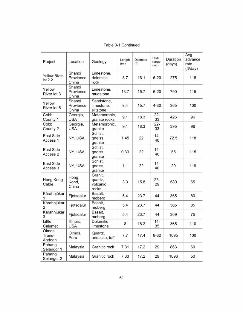
61
Table 3-1 Continued
Project Location Geology Length (mi)
Diameter (ft)
UCS range (ksi)
Duration (days)
Avg advance rate (ft/day)
Yellow River, lot 2-2
Shanxi Provience, China
Limestone, dolomitic rock
8.7 16.1 6-20 275 118
Yellow River lot 3
Shanxi Provience, China
Limestone, mudstone
13.7 15.7 6-20 790 115
Yellow River lot 5
Shanxi Provience, China
Sandstone, limestone, siltstone
8.4 15.7 4-30 365 100
Cobb County 1
Georgia, USA
Metamorphic, granite rocks
9.1 18.3 22-33
426 96
Cobb County 2
Georgia, USA
Metamorphic, granite
9.1 18.3 22-33
395 96
East Side Access 1
NY, USA Schist, gneiss, granite
1.45 22 14-40
72.5 118
East Side Access 2
NY, USA Schist, gneiss, granite
0.33 22 14-40
55 115
East Side Access 3
NY, USA Schist, gneiss, granite
1.1 22 14-40
20 119
Hong Kong Cable
Hong Kond, China
Granit, quartz, volcanic rocks
3.3 15.8 23-29
580 65
Kárahnjúkar 1
Fjotsdalur Basalt, moberg
5.4 23.7 44 365 80
Kárahnjúkar 2
Fjotsdalur Basalt, moberg
5.4 23.7 44 365 85
Kárahnjúkar 3
Fjotsdalur Basalt, moberg
5.4 23.7 44 369 75
Little Calumet
Illinois, USA
Dolomitic limestone
8 18.2 14-35
365 110
Olmos Trans-Andean
Olmos, Peru
Quartz, andesite, tuff
7.7 17.4 8-32 1095 100
Pahang Selangor 1
Malaysia Granitic rock 7.31 17.2 29 863 60
Pahang Selangor 2
Malaysia Granitic rock 7.33 17.2 29 1096 50
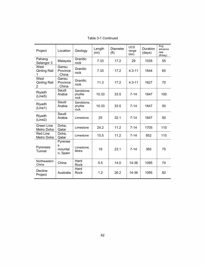
62
Table 3-1 Continued
Project Location Geology Length (mi)
Diameter (ft)
UCS range (ksi)
Duration (days)
Avg advance rate (ft/day)
Pahang Selangor 3
Malaysia Granitic rock
7.33 17.2 29 1035 55
West Qinling Rail 1
Gansu Province, China
Granitic rock
7.33 17.2 4.3-11 1644 65
West Qinling Rail 2
Gansu Province, China
Granitic rock
11.3 17.2 4.3-11 1627 70
Riyadh (Line5)
Saudi Arabia
Sandstone, phyllite rock
10.33 33.5 7-14 1647 100
Riyadh (Line1)
Saudi Arabia
Sandstone, phyllite rock
10.33 33.5 7-14 1647 50
Riyadh (Line2)
Saudi Arabia
Limestone 25 32.1 7-14 1647 50
Green Line Metro Doha
Doha, Qatar
Limestone 24.2 11.2 7-14 1705 110
Red Line Metro Doha
Doha, Qatar
Limestone 15.5 11.2 7-14 852 115
Pyrenees Tunnel
Pyrenees mountain, Spain
Limestone, Midra 19 23.1 7-14 365 75
Northeastern China China
Hard Rock
5.5 14.0 14-36 1095 74
Decline Project
Australia Hard Rock
1.2 26.2 14-36 1095 82

63
Table 3-2 Summary of case studies for SBUs
Project Location Geology Length (ft)
Diameter (ft)
UCS range (ksi)
Duration (days)
Avg advance rate (ft/day)
Shayler Run tunnel 1
Ohio, USA
Mixed ground
1,589 72 4-25 92 50
Shayler Run tunnel 2
Ohio, USA
Mixed ground
1,888 72 4-25 121 50
Shayler Run tunnel 3
Ohio, USA
Mixed ground
1,056 72 4-25 32 50
Shayler Run tunnel 4
Ohio, USA
Mixed ground
1,000 72 4-25 30 50
Shayler Run tunnel 5
Ohio, USA
Mixed ground
2,014 72 4-25 65 50
Shayler Run tunnel 6
Ohio, USA
Hard rock
1,320 72 4-25 31 40
Shayler Run tunnel 7
Ohio, USA
Hard rock
646 72 4-25 28 40
City of Clinton section 1
Iowa, USA
Hard clay
250 60 10< 49 20
City of Clinton section 2
Iowa, USA
Hard clay
270 42 10< 71 20
City of Clinton section 3
Iowa, USA
Hard clay
395 72 10< 44 30
Tahoe Forest Hospital 1
California, USA
Granite 70 30 4-25 9 10
Tahoe Forest Hospital 2
California, USA
Granite 70 30 4-25 10 10

64
Table 3-2 Continued
Project Location Geology Length (ft)
Diameter (ft)
UCS range (ksi)
Duration (days)
Avg advance rate (ft/day)
Tahoe Forest Hospital 3
California, USA
Granite 70 30 4-25 12 10
Chester Boulevard Sewer 1
Indiana, USA
Shale and limestone
400 54 10> 10 52
Chester Boulevard Sewer 2
Indiana, USA
Shale and limestone
400 54 10> 10 52
Chester Boulevard Sewer 3
Indiana, USA
Shale and limestone
180 48 10> 6 60
Chester Boulevard Sewer 4
Indiana, USA
Shale and limestone
180 48 10> 6 60
Milford Haven Project1
South Wales, U.K.
Siltstone mudstone
1766 48 10-29
15 60
Milford Haven Project2
South Wales, U.K.
Siltstone mudstone
1766 48 10-29
16 60
Milford Haven Project3
South Wales, U.K.
siltstone mudstone
1766 48 10-29
17 60
Kota City Project
Rajasthan, India
Quartzite rock
164 60 29-36
3 50
Kota City Project
Rajasthan, India
Quartzite rock
164 60 29-36
3 50
Glenwood Cable Tunnel
Southern Connecticut, USA
Quartz 220 60 5-20 6 40
Glenwood Cable Tunnel
Southern Connecticut, USA
Quartz 220 60 5-20 7 40
Locust Project 1
Oregon, USA
Clay, basalt
230 42 7-12 3 80
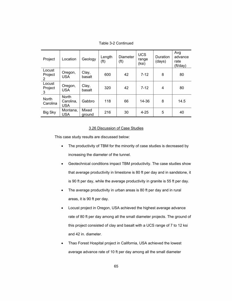
65
Table 3-2 Continued
Project Location Geology Length (ft)
Diameter (ft)
UCS range (ksi)
Duration (days)
Avg advance rate (ft/day)
Locust Project 2
Oregon, USA
Clay, basalt
600 42 7-12 8 80
Locust Project 3
Oregon, USA
Clay, basalt
320 42 7-12 4 80
North Carolina
North Carolina, USA
Gabbro 118 66 14-36 8 14.5
Big Sky Montana, USA
Mixed ground
216 30 4-25 5 40
3.26 Discussion of Case Studies
This case study results are discussed below:
The productivity of TBM for the minority of case studies is decreased by
increasing the diameter of the tunnel.
Geotechnical conditions impact TBM productivity. The case studies show
that average productivity in limestone is 80 ft per day and in sandstone, it
is 90 ft per day, while the average productivity in granite is 55 ft per day.
The average productivity in urban areas is 80 ft per day and in rural
areas, it is 90 ft per day.
Locust project in Oregon, USA achieved the highest average advance
rate of 80 ft per day among all the small diameter projects. The ground of
this project consisted of clay and basalt with a UCS range of 7 to 12 ksi
and 42 in. diameter.
Thao Forest Hospital project in California, USA achieved the lowest
average advance rate of 10 ft per day among all the small diameter
66
projects. The ground of this project were made of granite with the UCS of
25 ksi and 30 in. diameter.
Yellow River project in Shanxi, China achieved the highest average
advance rate of 120 ft per day among all the projects with category of
diameters more than 10 ft and less than 20 ft. The ground of this project
consisted of limestone, dolomite, and mudstone with UCS range of 6 to
20 ksi and 16 ft diameter.
The Pahang Selangor project in Malaysia achieved the lowest average
advance rate of 50 ft per day among all the projects with category of
diameters more than 10 ft and less than 20 ft. The ground was mostly
made of hard, abrasive granite with UCS of 30 ksi and 17 ft diameter.
East side access project in New York, USA achieved the highest
average advance rate of 120 ft per day among all the projects with
category of diameters more than 20 ft and less than 40 ft. The project
had mixed ground with UCS range of 14 to 40 ksi and 22 ft diameter.
Up to now, line 1 and 2 of Riyadh metro system project in Saudi Arabia
have achieved the lowest average advance rate of 50 ft per day among
all the projects with category of diameters more than 20 ft and less than
40 ft. The diameter of line 1 and 2 is 33.5 and 32.1 ft. The ground
consisted of sandstone, phyllite, and limestone with UCS range of 7 to
14 ksi.
3.24 Chapter Summary
A total of 23 case studies were reviewed, and evaluated. These case studies
presented different tunnel projects with different diameters, geological conditions, and
productivity. Also, case studies were discussed.

67
Chapter 4
Conclusions and Recommendation for Future Research
4.1 Introduction
In the previous chapter results were discussed. This chapter discusses the
conclusions from the research and recommends topics for future research in this area.
4.2 Conclusions
The subsequent list presents conclusions of this research:
An area's geotechnical conditions have the highest impact on TBM
productivity.
Because of work space limitations, the average productivity in urban
areas is 80 ft per day, which is less than rural area with productivity of 90
ft per day.
Among all the small diameter projects, the highest average advance rate
of 80 ft per day was achieved.
Among all the small diameter projects, the lowest average advance rate
of 10 ft per day was achieved.
Among all the projects with diameters of more than 10 ft and less than 20
ft, the highest average advance rate of 120 ft per day was achieved.
Among all of the projects with a category of diameters more than 10 ft
and less than 20 ft, the lowest average advance rate of 50 ft per day was
achieved.
Among all of the projects with a category of diameters more than 20 ft
and less than 40 ft, the highest average advance rate of 120 ft per day
was achieved.

68
4.3 Recommendation for Future Research
Due to limited time and resources, this thesis did not include a comprehensive
study of TBM productivity. Therefore, the recommendations for future research can be
summarized as follow:
Data collection from actual projects from considering all the factors.
Statistical analysis and modeling of TBM productivity.
Conceptual cost estimating of TBM usage for different diameters and site
and project conditions.

69
References
Abdallah, A. (2005). “The Use of Exploratory Tunnels as a tool for Scheduling and Cost
Estimation.” Proceedings of the Pipeline Division Specialty Conference, Reston,
VA, ASCE, 278-288.
Abd Al-Jalil, Y. (1998). “Analysis of Performance of Tunnel Boring Machine Based
Systems,” dissertation, presented to University of Texas at Austin, TX, in partial
fulfillment of the requirements for the degree of Doctor of Civil Engineering.
Advance Technology Consultants. “Tunnel Boring Machines”,
<http://www.advtechconsultants.com/TBMbasics.htm > (August. 12, 2016)
Delisio, A., Zhao, J., and Einstein, H.H. (2012). “Analysis and prediction of TBM
performance in blocky rock conditions at the Lötschberg Base Tunnel.”
Tunnelling and Underground Space Technology ,33 (2013) 131–142.
Farrokh, E. (2013). “Study of utilization factor and advance rate of hard rock TBMs.”
Dissertation, presented to The Pennsylvania State University, PA in Partial
Fulfillment of the Requirements for the Degree of Doctor of Philosophy.
Fuerst, T. (2012). " Method Statement for 1200mm (48") diameter Motorized Small
Boring Unit (SBU-M)." Solon, Ohio, The Robbins Company.
Girmscheid, G., and Schexnayder, C. (2003). “Tunnel boring machines.” Practice
Periodical on Structural Design and Construction, 2003, 8(3): 150-163
He, X., and Wu, Q. (2007). “Intelligent decision support system of type selection for
tunnel boring machine.” Journal of the China Railway Society, 29(3), 127-131.
Hegab, M. (2006). “Soil penetration Modeling in Microtunneling Projects.” Journal of
Construction Engineering and Management, ASCE, 132(6), 598-605.
International Society for Rock Mechanics commission on standardization of laboratory
and field tests (ISRM) (1978), “suggested methods for the quantitative

70
description of discontinuities in rock masses.”, Int. J. Rock Mech. Min Sci. &
Geomech, Abstr. Vol 15, pp. 319-368.
Ioannou, P.G. (1987). “Geologic prediction model for tunneling.” Journal of Construction
Engineering and Management, ASCE, 113(4), 569-590.
Ioannou, P.G. (1988a). “Geologic exploration and risk reduction in underground
construction.” Journal of Construction Engineering and Management, ASCE,
114(4), 532-547.
Ioannou, P.G. (1988b). “Pilot tunnels: contractor’s position.” Journal of Construction
Engineering and Management, ASCE, 114(4), 594-613.
Ioannou, P.G. (1989a). UM-CYCLONE user’s guide. Department of Civil Engineering,
University of Michigan, Ann Arbor, Michigan.
Ioannou, P.G. (1989b). “Evaluation of subsurface exploration programs.” Journal of
Construction Engineering and Management, ASCE, 115(4), 339-356.
Jencopale, N. (2013). “Improving productivity of tunnel boring machines” Thesis
presented to The University of Texas at Arlington, TX in Partial Fulfillment of the
Requirements for the Degree of Master of Science in Civil Engineering.
Laughton, C. (1998). “Evaluation and prediction of tunnel boring machine Performance in
Variable Rock Masses,’ dissertation, presented to University of Texas at Austin,
TX, in partial fulfillment of the requirements for the degree of Doctor of Civil
Engineering.
Likhitruangsilp, V., and Ioannou, P.G. (2004). “Risk-sensitive decision support system for
tunnel construction.” Proceedings of Geo-Trans, Reston, VA, ASCE/GEO, 1508-
1515.
Long, D., (2006). “Efficient excavation of small diameter utility installations in hard
rock." Tunnelling Association of Canada.

71
Maidl, B., Schmid, L., Ritz, W., and Herrenknecht, M. (2008). Hardrock Tunnel Boring
Machines, 1st Ed., Ernst & Sohn Verlag für Architektur und technische
Wissenschaften GmbH und Co.KG, Berlin.
Najafi, M. (2013), Trenchless Technology: Planning, Equipment, and Methods, 1st Ed.
McGraw-Hill, New York.
Najafi, M., and Ghokhale, S. (2005), Trenchless Technology: pipeline and utility design,
construction, and renewal, McGraw-Hill, New York.
NZ Geotechnical Society INC (2005). “Field description of soil and rock.”
Messinella, M. (2010). “Models for the analysis of tunneling construction processes”
Thesis presented to The Concordia University, Canada in Partial Fulfillment of
the Requirements for the Degree of Master of Science in Civil Engineering
Oliphant, J., Ibrahim, J.A.R., and Jowitt, P.W. (1996). “ASSIST: a computer-based
advisory system for site investigations.” Proceedings of the Institute of the Civil
Engineers and Geotechnical Engineering, 119-122.
Rahm, T., Sadri, K., Koch, C., Thewes, M., and Konig, M. (2012). “Advancement
Simulation of tunnel boring machines.” Proceedings of the 2012 Winter
Simulation Conference, Berlin, Germany.
Rostami, J. (2011). “TBM performance study for Jollyville Water Transmission main
WTP4 tunnel project,” TBM Consultant, State College, PA.
Rostami, J. (2016). “Performance prediction of hard rock Tunnel Boring Machines
(TBMs) in difficult ground.” Tunnelling and Underground Space Technology, 57
(2016) 173–182.
Salem, O., Galani, N., Najafi, M. (2003). “Productivity analysis of auger boring trenchless
pipe installation using simulation.” New Pipeline Technologies, Security, and
Safety.

72
Tarkoy, P.J., (2009). “Simple and practical TBM performance prediction.” Geomechanik
und Tunnelbau, 2(2), 128-139.
The Robbins Company. “Project results”,
<http://www.therobbinscompany.com/en/project-results/> (Dec. 16, 2016).
Toll, D.G. (1995). “The role of knowledge-based system in interpreting geotechnical
information.” Geotechnique, 45(3), 525-531.
Veidmark, A., and Sivesin, C. (2009). “The small boring unit: A ground-breaking
alternative to hand-dig installations in hard soil conditions.” The North American
Society for Trenchless Technology (NASTT) and the International Society for
Trenchless Technology (ISTT) International No-Dig Show.
Zheng, Y.L., Zhang, Q.B., and Zhao, J. (2016). “Challenges and opportunities of using
tunnel boring machines in mining.” Tunnelling and Underground Space
Technology, 57 (2016) 287–299.”

73
Appendix A
List of Acronyms
74
ABM Auger Boring Machine
AMR Alimineti Madhava Reddy
AR Advance Rate
ASSIST Advisory System for Site Investigations
Avg Average
BI Boreability Index
CLI Cutter Life Index
CMC Cooperative Muratori Cementisti
CMU Charlotte Mecklenburg Utilities
CUIRE Center for Underground Infrastructure Research and Education
DSS Decision Support System
DRI Drilling Rate Index
EPB Earth Pressure Balance
FPI Field Penetration Index
ft Foot/Feet
GSI Geological Strength Index
GWh Gigawatt hours
HAB Horizontal Auger Boring
In. Inch
JAL Jaiprakash Associates Ltd
JV Joint Venture
KV Kilovolt
ksi Kilopond per square inch
LNG Liquefied Natural Gas
m Meter
75
MPa Mega Pascal
MWRDGC Metropolitan Water Reclamation District of Greater Chicago
OD Outer Diameter
OPIC Odebrecht Peru Ingenieria y Construccion
P Penetration
P0 Pressure at Rest
Pa Active Pressure
Pp Passive Pressure
PR Penetration Rate
psi Pound per square inch
Q Rock Mass Classification System
RMR Rock Mass Rating
ROP Rate Of Penetration
ROW Right of Way
RPM Revolutions Per Minute
RQD Rock Quality Designation
RUIDP Rajasthan Urban Infrastructure Development Plan
SBU Small Boring Unit
Sdn Bhd Sendirian Berhad
SE Specific Energy
SNUI Shimizu, Nishimatsu, UEM, IJM
TARP Tunnel And Reservoir Project
TBM Tunnel Boring Machine
UFT Underground Freight Transportation
UCS Uniaxial Compressive Strength

76
Appendix B
List of Definitions
77
Anisotropic: A material is isotropic if its mechanical and elastic properties are the same
in all directions. When this is not true, the material is anisotropic.
Auger Boring Machine (ABM): An Auger Boring Machine (ABM) is used to bore
horizontally through soil or rock with a cutting head and auger.
Cutter Life Index (CLI): Specific wear number of disc cutters determined in laboratory
Tests.
Daily Advance Rate (daily AR): TBM advance speed computed by considering the TBM
delays due to rock supporting, maintenance, etc.
Drilling Rate Index (DRI): The most important input parameter of a commonly used
performance prediction model for tunnel boring machines.
Field Penetration Index (FPI): It represents the ‘‘boreability’’ of the rock with changing
geological/geotechnical conditions.
Joint: Joint is typically the weakest link in a tunnel.
Mica: Any of a group of hydrous potassium, aluminum silicate minerals. It is a type of
phyllosilicate, exhibiting a two-dimensional sheet or layer structure. Among the principal
rock-forming minerals, micas are found in all three major rock varieties which are
igneous, sedimentary, and metamorphic.
Mica Content: When describing soils in the field, the quantity of mica has been
expressed as a percent of area covered or it has been grouped into three classes: few (<
2 percent), common (2 to 20 percent), and many (> 20 percent).
Microtunneling: A trenchless construction method for installing pipelines. Microtunneling
uses all of the following features during construction: (1) Remote controlled––The
microtunneling-boring machine (MTBM) is operated from a control panel, normally
located on the surface. The system simultaneously installs pipe as spoil is excavated and
removed. Personnel entry is not required for routine operation. (2) Guided––The
78
guidance system usually references a laser beam projected onto a target in the MTBM,
capable of installing gravity sewers or other types of pipelines to the required tolerance,
for line and grade. (3) Pipe jacked–– The process of constructing a pipeline by
consecutively pushing pipes and MTBM through the ground using a jacking system for
thrust. (4) Continuously supported––Continuous pressure is provided to the face of the
excavation to balance groundwater and earth pressures.
Penetration Rate (PR): TBM advance speed computed without considering time
required for installing supports, TBM maintenance, etc.
Rock Quality Designation (RQD): It is an index of assessing rock quality quantitatively
and it was initially proposed by Deere (1963).
Small Boring Unit (SBU): The SBU is a small diameter rock cutting head that can be
used with any Auger Boring Machine (ABM).
Specific Energy: Energy needed for excavating a unit volume of rock.
TBM: Tunnel Boring Machine is used to mechanically excavate tunnels with a circular
cross section through a variety of soil and rock strata.
Tensile Strength: It measures the force required to pull something such as rope, wire, or
a structural beam or material to the point where it breaks. The tensile strength of a
material is the maximum amount of tensile stress that it can be subjected to before
failure.
Tunneling: This method follows the same process as pipe jacking, except that tunneling
method uses a temporary support structure while simultaneously excavate at the face
Uniaxial Compressive Strength (UCS): A measure of a material’s strength. The UCS is
the maximum longitudinal axial compressive stress that a right-cylindrical sample of
material can withstand. UCS tests were performed on trimmed core samples having a
length-to-diameter ratio of 2.0–2.5. The stress rate was applied within the limits of 145

79
psi. The tests were repeated five times for each rock type and the results were averaged.
The tests were carried out according to ISRM (1979) suggested method.
Utilization Factor (U) of the TBM: Amount of time in which the machine has been
effectively used for boring.

80
Biographical Information
Hamed Hashem Pour graduated in May 2014 with a Bachelor of Science in Civil
Engineering with specialty in road, bridge, railway, tunnel, and airport from Azad
University Central Branch, in Tehran, Iran. During his undergraduate education, he was
awarded a letter of appreciation for The Seventh Festival for Appreciation of Top
Researchers and Cultural Elites. Also he was awarded a competition certificate by
Concrete Research and Education Center, affiliated with ACI International Concrete
Institute.
After graduation, he continued his academic career for Master of Science in Civil
Engineering with a focus in Construction Engineering and Management at the University
of Texas at Arlington and graduated in December 2016. During his graduate studies, he
was awarded a graduate research assistantship (GRA) from the Civil Engineering
Department. During his graduate education he became interested in trenchless
technology and tunnel construction with TBMs (tunnel boring machines). He looks
forward to a successful future in the construction and infrastructure industry.


![Effect of Ultrasonic Sound Signal on Machinability Control ...pdfs.semanticscholar.org/7fc8/5b44f1f4c260633bdb5d2a9a7bd485fa984a.pdfprocess parameters was observed [5]. The productivity](https://img.pdfslide.us/doc/110x75/5f9eb292136fd103af1da3b8/effect-of-ultrasonic-sound-signal-on-machinability-control-pdfs-process-parameters.jpg)