Embed Size (px)
Citation preview

PM1730 Issue 1 (July 2019)
Studio 3Inset Convector Cassette
IMPORTANTTHE OUTER CASING, FRONT AND GLASS PANEL BECOME EXTREMELY HOT DURING
OPERATION AND WILL RESULT IN SERIOUS INJURY AND BURNS IF TOUCHED. IT IS THEREFORE RECOMMENDED THAT A FIREGUARD COMPLYING WITH BS 8423
(LATEST EDITION) IS USED IN THE PRESENCE OF YOUNG CHILDREN, THE ELDERLY OR INFIRM.
Do not attempt to burn rubbish in this appliance. Please read these Instructions carefully before installation or use.
Keep them in a safe place for future reference and when servicing the fire. The commissioning sheet found on page 3 of these instructions should be completed by the Installer.
Instructions for Use, Installation & ServicingFor use in GB & IE (Great Britain & Republic of Ireland).
2
Covering the following models:RVST-3HT
Studio Cassette - Inset Convector
Contents
DESIGN PROTECTIONThe Studio design, including it's frames and accessories, are
protected by European Design Registration No. 001169338 0002 0008.
Appliance Commissioning Checklist ......................3
User Instructions .......................................................4
Getting Started ...........................................................................4
User Instructions ........................................................................ 6
Care & Maintenance................................................................... 8
Troubleshooting ......................................................10
Installation Instructions ..........................................12
Installation Checklist ................................................................. 12
Pre-Installation Instructions ......................................................15
Installing the Appliance............................................................. 17
Commissioning .........................................................................29
Maintenance & Servicing ........................................31
Technical Appendix .................................................33
Information Requirement - Solid Fuel .....................................37
Spare Parts List ........................................................................ 38
Service Records .......................................................................39
If you have purchased your stove or fire from an authorised stockist within our Expert Retailer Network, then automatically your product will carry a 2 year warranty as standard. The 2 year warranty can be further extended to a total warranty period of 5 years by registering your Stovax Stove or Fireplace within one month of the latter of the purchase date or installation date. Accordingly, the start date for the warranty period is the date of purchase. During the registration process, the Expert Retailer details will be required for your Extended Warranty to be activated. Any product purchased outside of our Expert Retailer Network will carry a standard 12 month, non-extendable warranty.
It is a condition of the Extended Warranty that the installation complies with the relevant Building Regulations and is carried out by a suitably trained and qualified individual (HETAS in the UK or equivalent in other countries) with the certificate of installation and the Commissioning Report on Page 3 completed and retained by the end user.
Full terms and conditions are detailed in the Warranty Statement on the Stovax website www.stovax.com. In the event of any conflict of information the wording on the website shall prevail.
Important Note: Should any problems be experienced with your product, claims must first be submitted to the Expert Retailer where the appliance was purchased from who will offer immediate assistance or contact Stovax on your behalf.
3
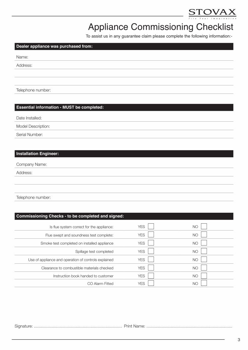
Dealer appliance was purchased from:
Name:
Address:
Telephone number:
Essential information - MUST be completed:
Date Installed:
Model Description:
Serial Number:
Installation Engineer:
Company Name:
Address:
Telephone number:
Commissioning Checks - to be completed and signed:
Is flue system correct for the appliance: YES NO
Flue swept and soundness test complete: YES NO
Smoke test completed on installed appliance YES NO
Spillage test completed YES NO
Use of appliance and operation of controls explained YES NO
Clearance to combustible materials checked YES NO
Instruction book handed to customer YES NO
CO Alarm Fitted YES NO
Signature: ............................................................................ Print Name: ..........................................................................
To assist us in any guarantee claim please complete the following information:-
Appliance Commissioning Checklist
4
Welcome
Congratulations on purchasing your Stovax Studio, if installed correctly Stovax hope it will give you many years of warmth and pleasure for which it was designed.
The purpose of this manual is to familiarise you with your stove, and give guidelines for its installation, operation and maintenance. If, after reading, you need further information, please do not hesitate to contact your Stovax retailer.
1. General Points
1.1 Before installation and/or use of this appliance please read these instructions fully and carefully to ensure that you have fully understood their requirements.
The appliance must be fitted by a registered installer*, or approved by your local building control officer.
1.2 All local regulations, including those referring to national
and European Standards need to be complied with when installing the appliance.
1.3 Only use for domestic heating in accordance with these operating instructions.
1.4 You must burn only approved fuels. Do not use with liquid fuels or as an incinerator.
1.5 Appliance surfaces become very hot when in use. Use a suitable fireguard‡ if young children, elderly or infirm persons are present.
Stovax offer firescreens, sparkguards and hearthgate systems for protection. Your Stovax dealer can advise you about these products.
1.6 Donotplacephotographs,TV’s,paintings,porcelainorother combustible items on the wall or near the appliance. Exposure to hot temperatures will cause damage. Do not place furniture or other items such as drying clothing closer than 1m from the front of this appliance.
WARNING: Extra fuel should not be stored on or next to the appliance. Only keep enough fuel for immediate use nearby and never leave the appliance unattended for long periods with any combustible material in close proximity.
1.7 Extractor fans or cooker hoods must not be placed in the same room or space as this can cause appliance to emit fumes into the room.
1.8 Do not obstruct inside or outside ventilation required for the safe use of this appliance.
1.9 Do not make unauthorised changes to the appliance.
1.10 The chimney must be swept at least once a year. See Section 12.
1.11 Do not onnect, or share, the same flue or chimney system with another appliance.
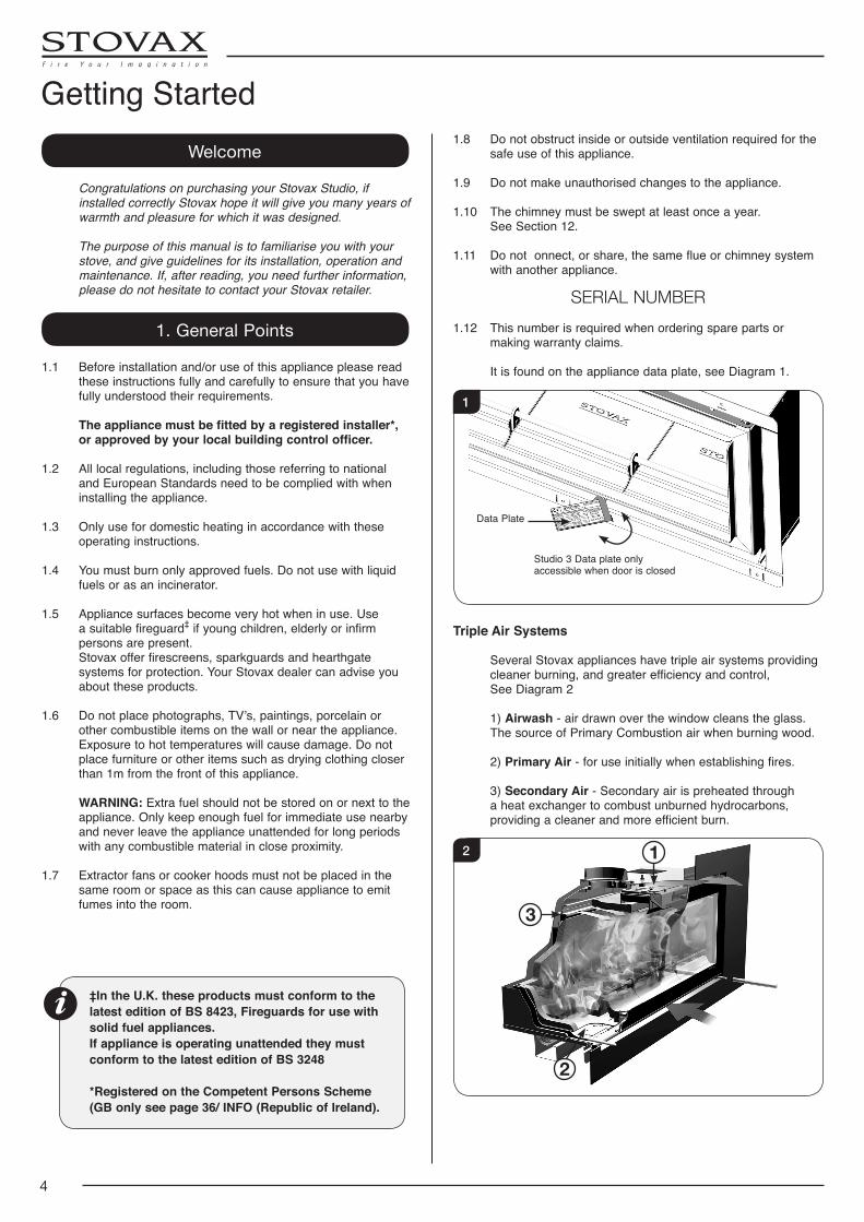
SERIAL NUMBER1.12 This number is required when ordering spare parts or
making warranty claims.
It is found on the appliance data plate, see Diagram 1.
1
Data Plate
Studio 3 Data plate only accessible when door is closed
Triple Air Systems
Several Stovax appliances have triple air systems providing cleaner burning, and greater efficiency and control,
See Diagram 2
1) Airwash - air drawn over the window cleans the glass. The source of Primary Combustion air when burning wood.
2) Primary Air - for use initially when establishing fires.
3) Secondary Air - Secondary air is preheated through a heat exchanger to combust unburned hydrocarbons, providing a cleaner and more efficient burn.
1
3
2
2
Getting Started
‡In the U.K. these products must conform to the latest edition of BS 8423, Fireguards for use with solid fuel appliances.If appliance is operating unattended they must conform to the latest edition of BS 3248
*Registered on the Competent Persons Scheme (GB only see page 36/ INFO (Republic of Ireland).
5
Airwash and Primary Air Controls
IMPORTANT: Stovax provide gauntlet style gloves for the users protection from heat and any sharp edges when using the appliance.For your safety ensure that gloves are always worn when opening, operating, refuelling or handling internal metalwork.
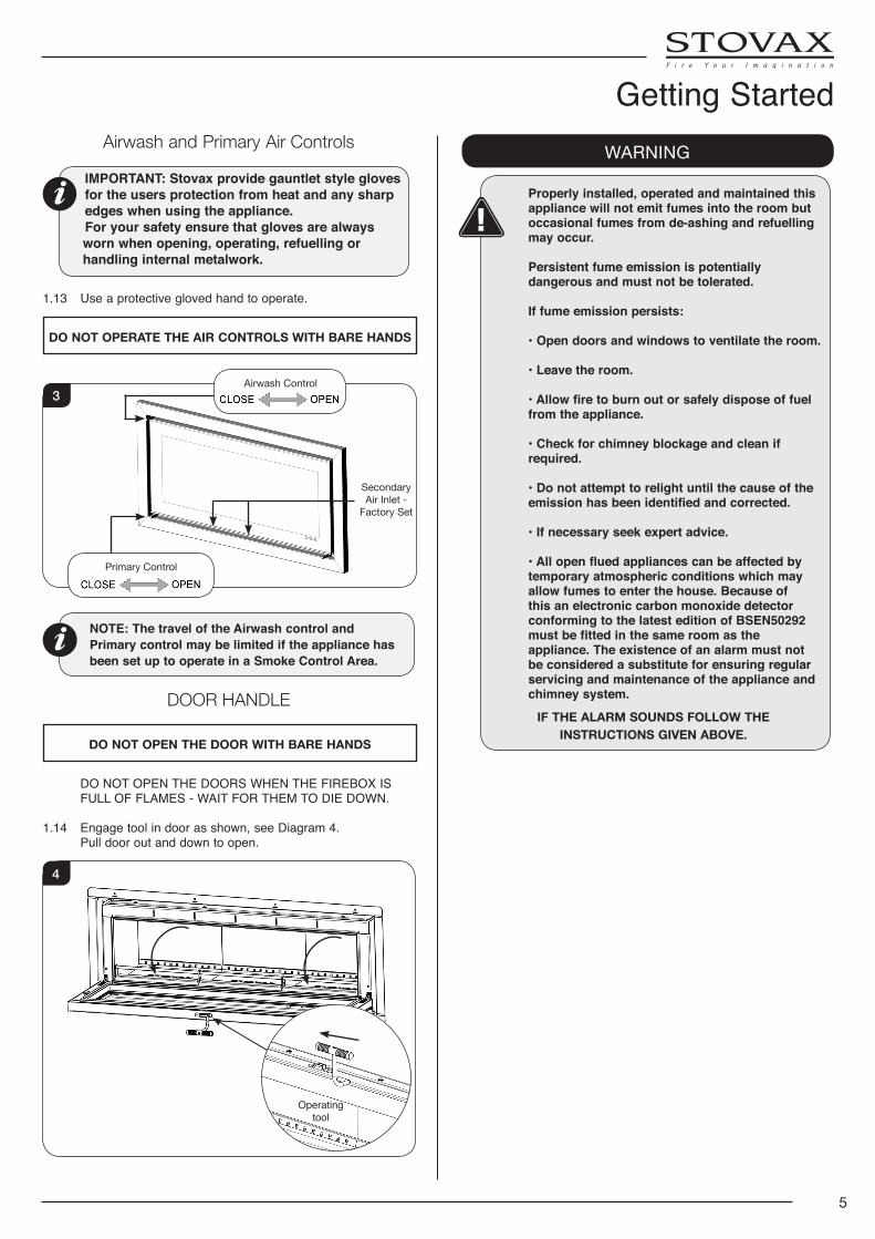
1.13 Use a protective gloved hand to operate.
DO NOT OPERATE THE AIR CONTROLS WITH BARE HANDS
Airwash Control
Secondary Air Inlet -
Factory Set
Primary Control
3
NOTE: The travel of the Airwash control and Primary control may be limited if the appliance has been set up to operate in a Smoke Control Area.
DOOR HANDLE
DO NOT OPEN THE DOOR WITH BARE HANDS
DO NOT OPEN THE DOORS WHEN THE FIREBOX IS FULL OF FLAMES - WAIT FOR THEM TO DIE DOWN.
1.14 Engage tool in door as shown, see Diagram 4. Pull door out and down to open.
Operating tool
4
WARNING
Properly installed, operated and maintained this appliance will not emit fumes into the room but occasional fumes from de-ashing and refuelling may occur.
Persistent fume emission is potentially dangerous and must not be tolerated.
If fume emission persists:
• Open doors and windows to ventilate the room.
• Leave the room.
• Allow fire to burn out or safely dispose of fuel from the appliance.
• Check for chimney blockage and clean if required.
• Do not attempt to relight until the cause of the emission has been identified and corrected.
• If necessary seek expert advice.
• All open flued appliances can be affected by temporary atmospheric conditions which may allow fumes to enter the house. Because of this an electronic carbon monoxide detector conforming to the latest edition of BSEN50292 must be fitted in the same room as the appliance. The existence of an alarm must not be considered a substitute for ensuring regular servicing and maintenance of the appliance and chimney system.
IF THE ALARM SOUNDS FOLLOW THE INSTRUCTIONS GIVEN ABOVE.
Getting Started
6
2. Using the Appliance for the First Time
2.1 To allow the appliance to settle, and fixing glues and paint to fully cure, operate the appliance at a low temperature for first few days.
2.2 Do not touch the paint during the first period of use.
2.3 During this time the appliance may give off some unpleasant odours. Keep the room well ventilated to avoid a build-up of fumes.
2.4 Please be aware that, during use, rope seals may discolour. This is normal.
3. Recommended Fuels
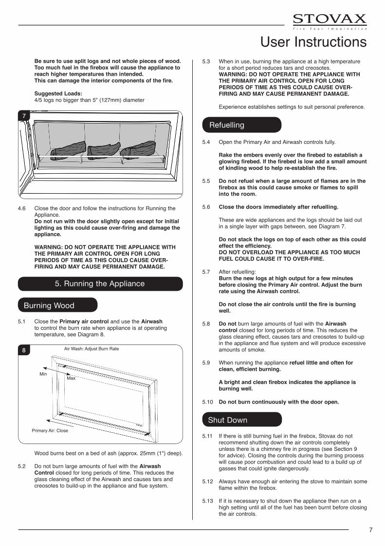
3.1 Wood Logs:
Burn only seasoned timber with a moisture content of less than 20%. To ensure this allow cut wood to dry for 12 to 18 months.
Wood Length
Appliance Wood Length
Studio 3 250mm - 500mm
5
Poor quality timber: — Causes low combustion efficiency — Produces harmful condensation — Reduces effectiveness of the airwash and life of
the appliance
Do not burn construction timber, painted, impregnated / treated wood, manufactured board products or pallet wood.
3.2 Fuel consumption. As tested at nominal heat output to the requirements of EN
13229: 2001 for intermittent operation:
DescriptionFuel Consumption
Kg/hour Wood
Studio 3 3.6 A number of factors can affect the performance of the
appliance. See Troubleshooting Section for details.
Fuel Overloading The maximum amount of fuel specified in this manual
should not be exceeded, overloading can cause excess smoke.
4. Lighting the Appliance
IMPORTANT: Stovax provide gauntlet style gloves for the users protection from heat and any sharp edges when using the appliance.For your safety ensure that gloves are always worn when opening, operating, refuelling or handling internal metalwork.
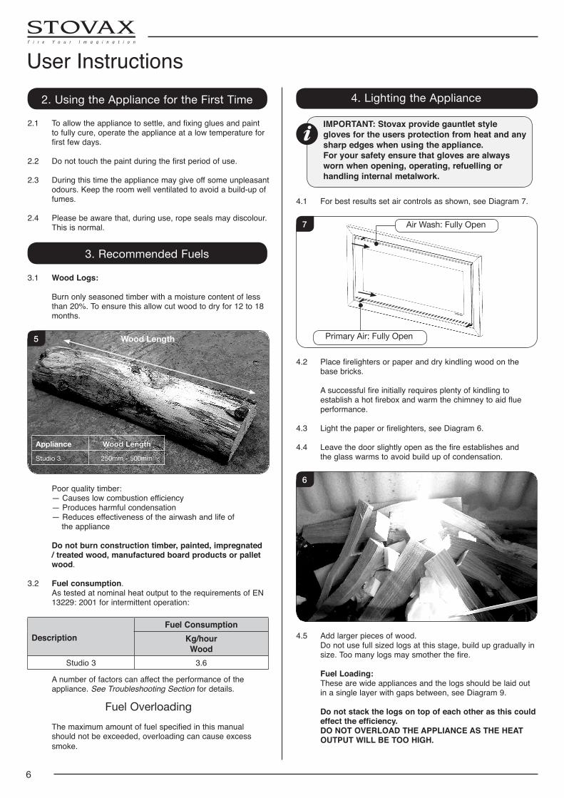
4.1 For best results set air controls as shown, see Diagram 7.
Air Wash: Fully Open
Primary Air: Fully Open
7
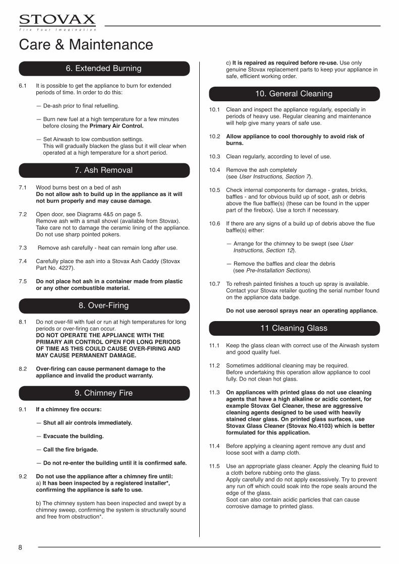
4.2 Place firelighters or paper and dry kindling wood on the base bricks.
A successful fire initially requires plenty of kindling to establish a hot firebox and warm the chimney to aid flue performance.
4.3 Light the paper or firelighters, see Diagram 6.
4.4 Leave the door slightly open as the fire establishes and the glass warms to avoid build up of condensation.
6
4.5 Add larger pieces of wood. Do not use full sized logs at this stage, build up gradually in
size. Too many logs may smother the fire.
Fuel Loading: These are wide appliances and the logs should be laid out
in a single layer with gaps between, see Diagram 9.
Do not stack the logs on top of each other as this could effect the efficiency.
DO NOT OVERLOAD THE APPLIANCE AS THE HEAT OUTPUT WILL BE TOO HIGH.
User Instructions
7
5.3 When in use, burning the appliance at a high temperature for a short period reduces tars and creosotes.
WARNING: DO NOT OPERATE THE APPLIANCE WITH THE PRIMARY AIR CONTROL OPEN FOR LONG PERIODS OF TIME AS THIS COULD CAUSE OVER-FIRING AND MAY CAUSE PERMANENT DAMAGE.
Experience establishes settings to suit personal preference.
Refuelling
5.4 Open the Primary Air and Airwash controls fully.
Rake the embers evenly over the firebed to establish a glowing firebed. If the firebed is low add a small amount of kindling wood to help re-establish the fire.
5.5 Do not refuel when a large amount of flames are in the firebox as this could cause smoke or flames to spill into the room.
5.6 Close the doors immediately after refuelling.
These are wide appliances and the logs should be laid out in a single layer with gaps between, see Diagram 7.
Do not stack the logs on top of each other as this could effect the efficiency.
DO NOT OVERLOAD THE APPLIANCE AS TOO MUCH FUEL COULD CAUSE IT TO OVER-FIRE.
5.7 After refuelling: Burn the new logs at high output for a few minutes
before closing the Primary Air control. Adjust the burn rate using the Airwash control.
Do not close the air controls until the fire is burning well.
5.8 Do not burn large amounts of fuel with the Airwash control closed for long periods of time. This reduces the glass cleaning effect, causes tars and creosotes to build-up in the appliance and flue system and will produce excessive amounts of smoke.
5.9 When running the appliance refuel little and often for clean, efficient burning.
A bright and clean firebox indicates the appliance is burning well.
5.10 Do not burn continuously with the door open.
Shut Down
5.11 If there is still burning fuel in the firebox, Stovax do not recommend shutting down the air controls completely unless there is a chimney fire in progress (see Section 9 for advice). Closing the controls during the burning process will cause poor combustion and could lead to a build up of gasses that could ignite dangerously.
5.12 Always have enough air entering the stove to maintain some flame within the firebox.
5.13 If it is necessary to shut down the appliance then run on a high setting until all of the fuel has been burnt before closing the air controls.
Be sure to use split logs and not whole pieces of wood. Too much fuel in the firebox will cause the appliance to reach higher temperatures than intended.
This can damage the interior components of the fire.
Suggested Loads: 4/5 logs no bigger than 5" (127mm) diameter
7
4.6 Close the door and follow the instructions for Running the Appliance.
Do not run with the door slightly open except for initial lighting as this could cause over-firing and damage the appliance.
WARNING: DO NOT OPERATE THE APPLIANCE WITH THE PRIMARY AIR CONTROL OPEN FOR LONG PERIODS OF TIME AS THIS COULD CAUSE OVER-FIRING AND MAY CAUSE PERMANENT DAMAGE.
5. Running the Appliance
Burning Wood
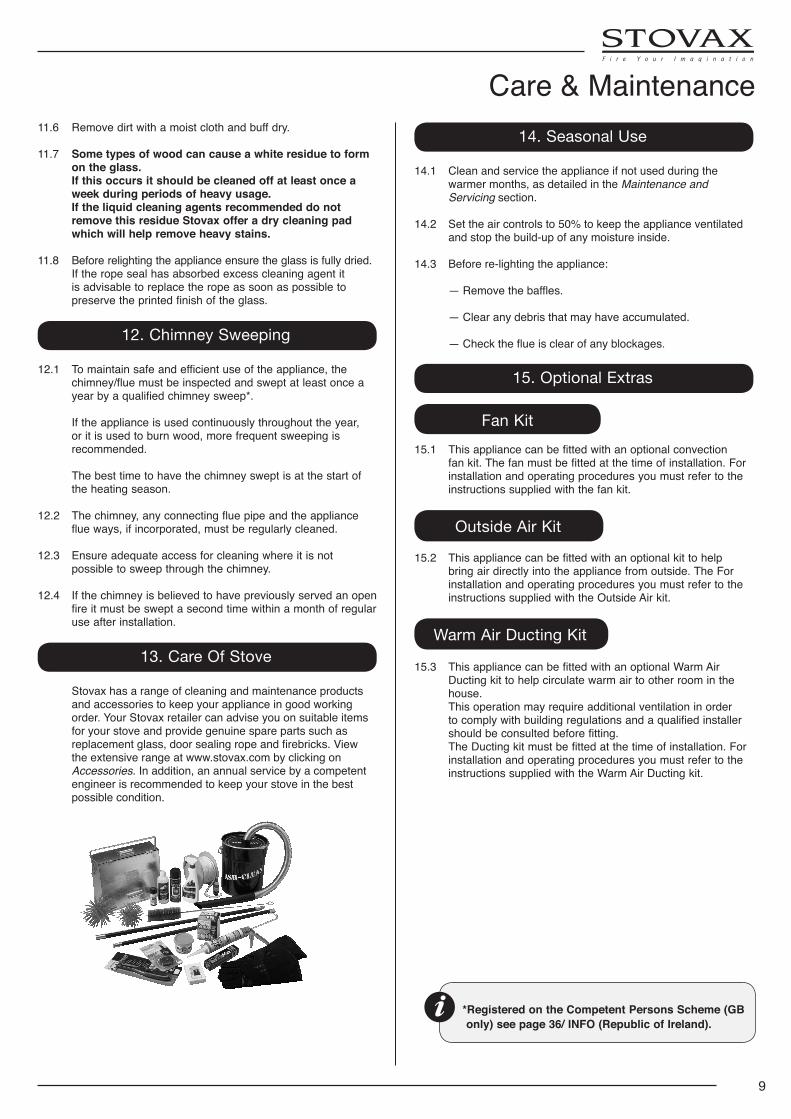
5.1 Close the Primary air control and use the Airwash to control the burn rate when appliance is at operating temperature, see Diagram 8.
Air Wash: Adjust Burn Rate
Primary Air: Close
MinMax
8
Wood burns best on a bed of ash (approx. 25mm (1") deep).
5.2 Do not burn large amounts of fuel with the Airwash Control closed for long periods of time. This reduces the glass cleaning effect of the Airwash and causes tars and creosotes to build-up in the appliance and flue system.
User Instructions
8
c) It is repaired as required before re-use. Use only genuine Stovax replacement parts to keep your appliance in safe, efficient working order.
10. General Cleaning
10.1 Clean and inspect the appliance regularly, especially in periods of heavy use. Regular cleaning and maintenance will help give many years of safe use.
10.2 Allow appliance to cool thoroughly to avoid risk of burns.
10.3 Clean regularly, according to level of use.
10.4 Remove the ash completely (see User Instructions, Section 7).
10.5 Check internal components for damage - grates, bricks, baffles - and for obvious build up of soot, ash or debris above the flue baffle(s) (these can be found in the upper part of the firebox). Use a torch if necessary.
10.6 If there are any signs of a build up of debris above the flue baffle(s) either:
— Arrange for the chimney to be swept (see User Instructions, Section 12).
— Remove the baffles and clear the debris (see Pre-Installation Sections).
10.7 Torefreshpaintedfinishesatouchupsprayisavailable.Contact your Stovax retailer quoting the serial number found on the appliance data badge.
Do not use aerosol sprays near an operating appliance.
11 Cleaning Glass
11.1 Keep the glass clean with correct use of the Airwash system and good quality fuel.
11.2 Sometimes additional cleaning may be required. Before undertaking this operation allow appliance to cool
fully. Do not clean hot glass. 11.3 On appliances with printed glass do not use cleaning
agents that have a high alkaline or acidic content, for example Stovax Gel Cleaner, these are aggressive cleaning agents designed to be used with heavily stained clear glass. On printed glass surfaces, use Stovax Glass Cleaner (Stovax No.4103) which is better formulated for this application.
11.4 Before applying a cleaning agent remove any dust and
loose soot with a damp cloth. 11.5 Use an appropriate glass cleaner. Apply the cleaning fluid to
a cloth before rubbing onto the glass. Apply carefully and do not apply excessively. Try to prevent
any run off which could soak into the rope seals around the edge of the glass.
Soot can also contain acidic particles that can cause corrosive damage to printed glass.
6. Extended Burning
6.1 It is possible to get the appliance to burn for extended periods of time. In order to do this:
—De-ashpriortofinalrefuelling.
— Burn new fuel at a high temperature for a few minutes before closing the Primary Air Control.
— Set Airwash to low combustion settings. This will gradually blacken the glass but it will clear when
operated at a high temperature for a short period.
7. Ash Removal
7.1 Wood burns best on a bed of ash Do not allow ash to build up in the appliance as it will
not burn properly and may cause damage.
7.2 Open door, see Diagrams 4&5 on page 5. Remove ash with a small shovel (available from Stovax).
Take care not to damage the ceramic lining of the appliance. Do not use sharp pointed pokers.
7.3 Remove ash carefully - heat can remain long after use. 7.4 Carefully place the ash into a Stovax Ash Caddy (Stovax
Part No. 4227).
7.5 Do not place hot ash in a container made from plastic or any other combustible material.
8. Over-Firing
8.1 Do not over-fill with fuel or run at high temperatures for long periods or over-firing can occur.
DO NOT OPERATE THE APPLIANCE WITH THE PRIMARY AIR CONTROL OPEN FOR LONG PERIODS OF TIME AS THIS COULD CAUSE OVER-FIRING AND MAY CAUSE PERMANENT DAMAGE.
8.2 Over-firing can cause permanent damage to the appliance and invalid the product warranty.
9. Chimney Fire
9.1 If a chimney fire occurs:
— Shut all air controls immediately.
— Evacuate the building.
— Call the fire brigade.
— Do not re-enter the building until it is confirmed safe.
9.2 Do not use the appliance after a chimney fire until: a) It has been inspected by a registered installer*,
confirming the appliance is safe to use.
b) The chimney system has been inspected and swept by a chimney sweep, confirming the system is structurally sound and free from obstruction*.
Care & Maintenance
9
Care & Maintenance
*Registered on the Competent Persons Scheme (GB only) see page 36/ INFO (Republic of Ireland).
11.6 Remove dirt with a moist cloth and buff dry. 11.7 Some types of wood can cause a white residue to form
on the glass. If this occurs it should be cleaned off at least once a
week during periods of heavy usage. If the liquid cleaning agents recommended do not
remove this residue Stovax offer a dry cleaning pad which will help remove heavy stains.
11.8 Before relighting the appliance ensure the glass is fully dried. If the rope seal has absorbed excess cleaning agent it
is advisable to replace the rope as soon as possible to preserve the printed finish of the glass.
12. Chimney Sweeping
12.1 To maintain safe and efficient use of the appliance, the chimney/flue must be inspected and swept at least once a year by a qualified chimney sweep*.
If the appliance is used continuously throughout the year, or it is used to burn wood, more frequent sweeping is recommended.
The best time to have the chimney swept is at the start of the heating season.
12.2 The chimney, any connecting flue pipe and the appliance flue ways, if incorporated, must be regularly cleaned.
12.3 Ensure adequate access for cleaning where it is not possible to sweep through the chimney.
12.4 If the chimney is believed to have previously served an open fire it must be swept a second time within a month of regular use after installation.
13. Care Of Stove
Stovax has a range of cleaning and maintenance products and accessories to keep your appliance in good working order. Your Stovax retailer can advise you on suitable items for your stove and provide genuine spare parts such as replacementglass,doorsealingropeandfirebricks.Viewthe extensive range at www.stovax.com by clicking on Accessories. In addition, an annual service by a competent engineer is recommended to keep your stove in the best possible condition.
14. Seasonal Use
14.1 Clean and service the appliance if not used during the warmer months, as detailed in the Maintenance and Servicing section.
14.2 Set the air controls to 50% to keep the appliance ventilated and stop the build-up of any moisture inside.
14.3 Before re-lighting the appliance:
— Remove the baffles.
— Clear any debris that may have accumulated.
— Check the flue is clear of any blockages.
15. Optional Extras
Fan Kit15.1 This appliance can be fitted with an optional convection
fan kit. The fan must be fitted at the time of installation. For installation and operating procedures you must refer to the instructions supplied with the fan kit.
Outside Air Kit
15.2 This appliance can be fitted with an optional kit to help bring air directly into the appliance from outside. The For installation and operating procedures you must refer to the instructions supplied with the Outside Air kit.
Warm Air Ducting Kit
15.3 This appliance can be fitted with an optional Warm Air Ducting kit to help circulate warm air to other room in the house.
This operation may require additional ventilation in order to comply with building regulations and a qualified installer should be consulted before fitting.
The Ducting kit must be fitted at the time of installation. For installation and operating procedures you must refer to the instructions supplied with the Warm Air Ducting kit.
10
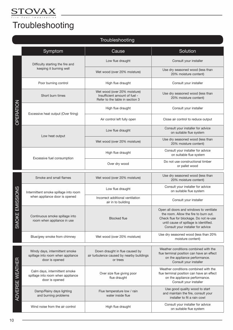
Troubleshooting
Symptom Cause Solution
OPE
RATI
ON
Difficulty starting the fire andkeeping it burning well
Low flue draught Consult your installer
Wet wood (over 20% moisture) Use dry seasoned wood (less than20% moisture content)
Poor burning control High flue draught Consult your installer
Short burn timesWet wood (over 20% moisture)
Insufficient amount of fuel -Refer to the table in section 3
Use dry seasoned wood (less than20% moisture content)
Excessive heat output (Over firing)High flue draught Consult your installer
Air control left fully open Close air control to reduce output
Low heat outputLow flue draught Consult your installer for advice
on suitable flue system
Wet wood (over 20% moisture) Use dry seasoned wood (less than20% moisture content)
Excessive fuel consumptionHigh flue draught Consult your installer for advice
on suitable flue system
Over dry wood Do not use constructional timberor pallet wood
SMO
KE E
MIS
SIO
NS
Smoke and small flames Wet wood (over 20% moisture) Use dry seasoned wood (less than20% moisture content)
Intermittent smoke spillage into room when appliance door is opened
Low flue draught Consult your installer for adviceon suitable flue system
Incorrect additional ventilationair in to building Consult your installer
Continuous smoke spillage intoroom when appliance in use Blocked flue
Open all doors and windows to ventilatethe room. Allow the fire to burn out.
Check flue for blockage. Do not re-useuntil cause of spillage is identified.
Consult your installer for advice
Blue/grey smoke from chimney Wet wood (over 20% moisture) Use dry seasoned wood (less than 20% moisture content)
ADVE
RSE
WEA
THER
Windy days, intermittent smokespillage into room when appliance
door is opened
Down draught in flue caused byair turbulence caused by nearby buildings
or trees
Weather conditions combined with theflue terminal position can have an effect
on the appliance performance.Consult your installer
Calm days, intermittent smokespillage into room when appliance
door is opened
Over size flue giving poorflue draught
Weather conditions combined with theflue terminal position can have an effect
on the appliance performance.Consult your installer
Damp/Rainy days lightingand burning problems
Flue temperature low / rainwater inside flue
Use good quality wood to startand maintain the fire, consult your
installer to fit a rain cowl
Wind noise from the air control High flue draught Consult your installer for adviceon suitable flue system
Troubleshooting
11
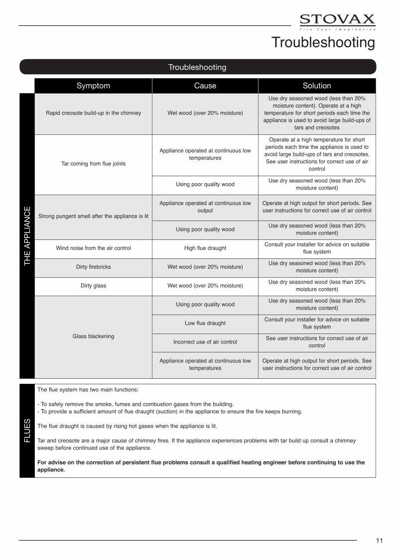
Troubleshooting
Symptom Cause Solution
THE
APPL
IANC
E
Rapid creosote build-up in the chimney Wet wood (over 20% moisture)
Use dry seasoned wood (less than 20% moisture content). Operate at a high
temperature for short periods each time the appliance is used to avoid large build-ups of
tars and creosotes
Tar coming from flue joints
Appliance operated at continuous low temperatures
Operate at a high temperature for short periods each time the appliance is used to avoid large build-ups of tars and creosotes. See user instructions for correct use of air
control
Using poor quality wood Use dry seasoned wood (less than 20% moisture content)
Strong pungent smell after the appliance is lit
Appliance operated at continuous low output
Operate at high output for short periods. See user instructions for correct use of air control
Using poor quality wood Use dry seasoned wood (less than 20% moisture content)
Wind noise from the air control High flue draught Consult your installer for advice on suitable flue system
Dirty firebricks Wet wood (over 20% moisture) Use dry seasoned wood (less than 20% moisture content)
Dirty glass Wet wood (over 20% moisture) Use dry seasoned wood (less than 20% moisture content)
Glass blackening
Using poor quality wood Use dry seasoned wood (less than 20% moisture content)
Low flue draught Consult your installer for advice on suitable flue system
Incorrect use of air control See user instructions for correct use of air control
Appliance operated at continuous low temperatures
Operate at high output for short periods. See user instructions for correct use of air control
FLUE
S
The flue system has two main functions:
- To safely remove the smoke, fumes and combustion gases from the building.- To provide a sufficient amount of flue draught (suction) in the appliance to ensure the fire keeps burning.
The flue draught is caused by rising hot gases when the appliance is lit.
Tar and creosote are a major cause of chimney fires. If the appliance experiences problems with tar build up consult a chimney sweep before continued use of the appliance.
For advise on the correction of persistent flue problems consult a qualified heating engineer before continuing to use the appliance.
Troubleshooting
12
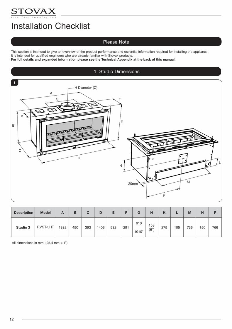
Installation ChecklistPlease Note
This section is intended to give an overview of the product performance and essential information required for installing the appliance.It is intended for qualified engineers who are already familiar with Stovax products. For full details and expanded information please see the Technical Appendix at the back of this manual.
1. Studio Dimensions
All dimensions in mm. (25.4 mm = 1”)
Description Model A B C D E F G H K L M N P
Studio 3 RVST-3HT 1332 450 393 1406 532 291610
1010*
153 (6") 275 105 736 150 766
20mm
H Diameter (Ø)
M
N
P
D
C
B
AG F
EK
L
1
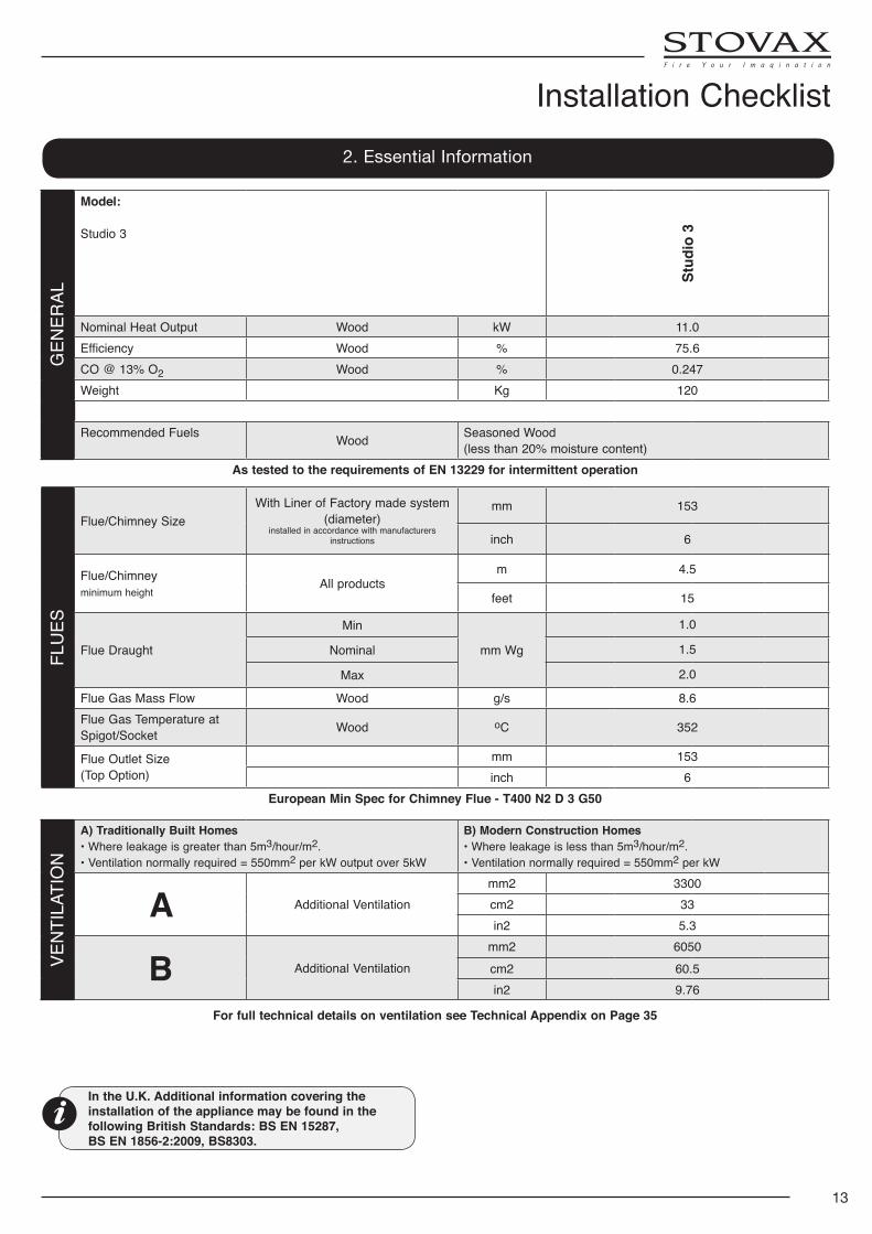
13
Installation ChecklistG
ENER
AL
Model:
Studio 3
Stud
io 3
Nominal Heat Output Wood kW 11.0Efficiency Wood % 75.6CO @ 13% O2 Wood % 0.247Weight Kg 120
Recommended Fuels Wood Seasoned Wood (less than 20% moisture content)
As tested to the requirements of EN 13229 for intermittent operation
FLU
ES
Flue/Chimney SizeWith Liner of Factory made system
(diameter)installed in accordance with manufacturers
instructions
mm 153
inch 6
Flue/Chimney minimum height
All productsm 4.5
feet 15
Flue Draught
Min
mm Wg
1.0
Nominal 1.5
Max 2.0
Flue Gas Mass Flow Wood g/s 8.6Flue Gas Temperature at Spigot/Socket Wood oC 352
Flue Outlet Size(Top Option)
mm 153inch 6
European Min Spec for Chimney Flue - T400 N2 D 3 G50
VEN
TILA
TIO
N
A) Traditionally Built Homes• Where leakage is greater than 5m3/hour/m2.• Ventilation normally required = 550mm2 per kW output over 5kW
B) Modern Construction Homes• Where leakage is less than 5m3/hour/m2.• Ventilation normally required = 550mm2 per kW
A Additional Ventilationmm2 3300cm2 33in2 5.3
B Additional Ventilationmm2 6050cm2 60.5in2 9.76
For full technical details on ventilation see Technical Appendix on Page 35
2. Essential Information
In the U.K. Additional information covering the installation of the appliance may be found in the following British Standards: BS EN 15287, BS EN 1856-2:2009, BS8303.
14
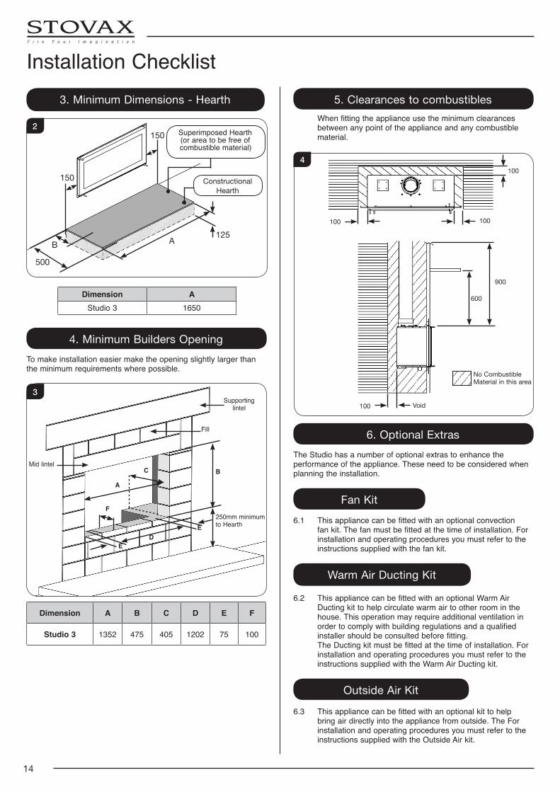
Installation Checklist3. Minimum Dimensions - Hearth
150
150
B
500
A125
Superimposed Hearth(or area to be free of combustible material)
Constructional Hearth
2
Dimension AStudio 3 1650
4. Minimum Builders OpeningTo make installation easier make the opening slightly larger than the minimum requirements where possible.
A
BC
DE
E
F
Supporting lintel
Fill
Mid lintel
250mm minimum to Hearth
3
Dimension A B C D E F
Studio 3 1352 475 405 1202 75 100
5. Clearances to combustibles When fitting the appliance use the minimum clearances
between any point of the appliance and any combustible material.
100
100
100
100
900
600
Void
No Combustible Material in this area
4
6. Optional ExtrasThe Studio has a number of optional extras to enhance the performance of the appliance. These need to be considered when planning the installation.
Fan Kit6.1 This appliance can be fitted with an optional convection
fan kit. The fan must be fitted at the time of installation. For installation and operating procedures you must refer to the instructions supplied with the fan kit.
Warm Air Ducting Kit
6.2 This appliance can be fitted with an optional Warm Air Ducting kit to help circulate warm air to other room in the house. This operation may require additional ventilation in order to comply with building regulations and a qualified installer should be consulted before fitting.
The Ducting kit must be fitted at the time of installation. For installation and operating procedures you must refer to the instructions supplied with the Warm Air Ducting kit.
Outside Air Kit6.3 This appliance can be fitted with an optional kit to help
bring air directly into the appliance from outside. The For installation and operating procedures you must refer to the instructions supplied with the Outside Air kit.
15
1. General
1.1 To make the installation of the appliance easier it is best to remove the internal components before fitting into the builders opening/studwork.
1.2 For the best results removing the following components as set out below.
2. Removal of the Door
This will require 2 people. 2.1 Open the door fully (see User Instructions, page 5).
2.2 Lock the hinges in position using a ø3mm pin as shown in Diagram 1.
ø3mm pin in each hinge1
2.3 Raise the door vertically at the front.
2.4 Lower the door approximately 5mm and pull away from the appliance.
2.5 Lie the door face down on a soft flat surface to protect the paint work and glass.
2.6 Reverse the procedure to refit the door.
3. Removal of Internal Components
In the firebox of the Studio are several loose items including:
• A box containing: Baffle Bricks Firebricks Bag containing Instruction Manual, Warranty & Door Tool,
Log Guard End Supports • Log Guard • Front Baffle Support
3.1 Remove these carefully and put them safely to one side. They can be fitted after the appliance has been installed,
see Installation Section.
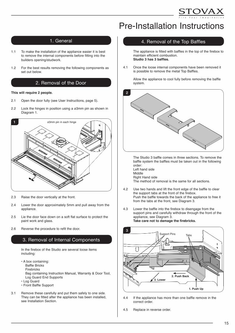
4. Removal of the Top Baffles
The appliance is fitted with baffles in the top of the firebox to maintain efficient combustion.
Studio 3 has 3 baffles.
4.1 Once the loose internal components have been removed it is possible to remove the metal Top Baffles.
Allow the appliance to cool fully before removing the baffle system.
2
The Studio 3 baffle comes in three sections. To remove the baffle system the baffles must be taken out in the following order:
Left hand side Middle Right Hand side The method of removal is the same for all sections.
4.2 Use two hands and lift the front edge of the baffle to clear the support tabs at the front of the firebox.
Push the baffle towards the back of the appliance to free it from the tabs at the front, see Diagram 3.
4.3 Lower the baffle into the firebox to disengage from the support pins and carefully withdraw through the front of the appliance, see Diagram 3.
Take care not to damage the firebricks.
3Support Pins Tabs
1. Push Up
2. Push Back3. Lower
4.4 If the appliance has more than one baffle remove in the correct order.
4.5 Replace in reverse order.
Pre-Installation Instructions
16
Pre-Installation Instructions4.6 The baffle system is designed to give safe and efficient
operation of the stove. Replace damaged baffles immediately.
4.7 Do not modify the baffle system. Do not operate with the baffle system removed.
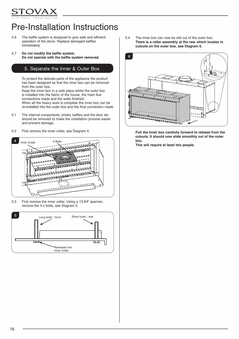
5. Separate the Inner & Outer Box
To protect the delicate parts of the appliance the product has been designed so that the inner box can be removed from the outer box.
Keep the inner box in a safe place whilst the outer box is installed into the fabric of the house, the main flue connections made and the walls finished.
When all the heavy work is complete the inner box can be re-installed into the outer box and the final connection made.
5.1 The internal components, bricks, baffles and the door etc should be removed to make the installation process easier and prevent damage.
5.2 First remove the inner collar, see Diagram 4.
Inner Collar 4 Bolts4
5.3 First remove the inner collar. Using a 13 A/F spanner, remove the 4 x bolts, see Diagram 5.
Recessed into Inner Collar
Long bolts - front Short bolts - rear5
5.4 The inner box can now be slid out of the outer box. There is a roller assembly at the rear which locates in
cutouts on the outer box, see Diagram 6.
6
Pull the inner box carefully forward to release from the cutouts. It should now slide smoothly out of the outer box.
This will require at least two people.
17
1. Installing the Appliance
Each installation is unique to the property so it is not possible to give details to suit every setting. The installation must comply with Building Regulations† and be made using "best practice" construction methods‡.
The clearance to combustible materials for the Stovax Studio models is greatly different due to the higher temperatures that the appliance can reach. Extra care must be taken when creating a builders opening. Pay careful attention to the distance to combustible materials recommended and ensure the housing for the appliance is built from non-combustible material.
Many fireplace openings have a supporting lintel. Do not remove without supporting the remaining structure of the building. Do not support the structure with the appliance or the flue system.
1.1 Take care when installing the appliance. Careless handling and use of tools can damage the finish and/or area.
There are two types of installation for this appliance:
Fitting to a Masonry Chimney - Section 2.
Studwork Installation - Section 3, 4 & 5.
All methods of installation will require the attachment of frame fixing brackets prior to the installation of the outer box see Section 3.6.
NOTE: If installing with an Outside Air Kit, please consult manual PM361 prior to installation.
2. Fitting to A Masonry Chimney
2.1 Many fireplace openings have a supporting lintel. Do not remove without supporting the remaining structure of the building. Do not support the structure with the appliance or the flue system.
Stovax recommend the use of a flue liner when installing into a masonry chimney. Alternative methods can be used if the chimney is sound and correctly sized, however access may be required to make an effective seal - ie Using a sump adapter.
Important Note: If you plan to install an optional fan kit
preparation must be made for the installation of wiring and sockets.
250mm minimum if fan kit fitted
Ensure provision for a vent of at
least 200 cm2 is made
1
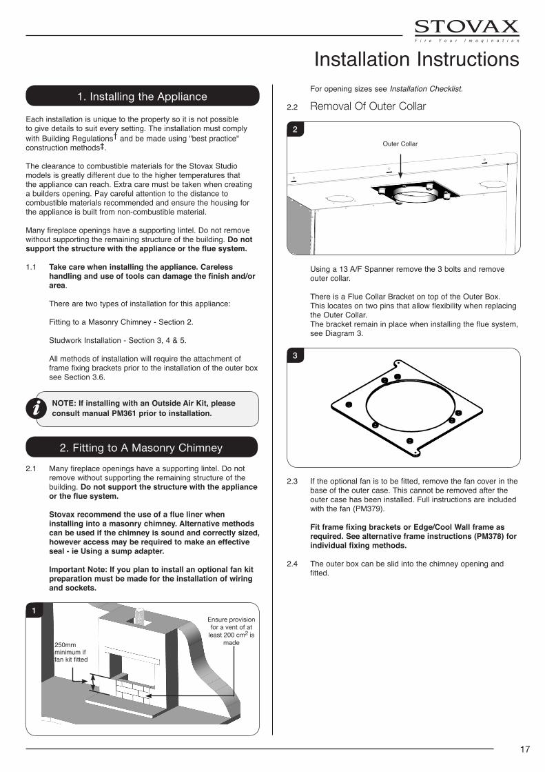
For opening sizes see Installation Checklist.
2.2 Removal Of Outer Collar
Outer Collar
2
Using a 13 A/F Spanner remove the 3 bolts and remove outer collar.
There is a Flue Collar Bracket on top of the Outer Box. This locates on two pins that allow flexibility when replacing
the Outer Collar. The bracket remain in place when installing the flue system,
see Diagram 3.
3
2.3 If the optional fan is to be fitted, remove the fan cover in the base of the outer case. This cannot be removed after the outer case has been installed. Full instructions are included with the fan (PM379).
Fit frame fixing brackets or Edge/Cool Wall frame as required. See alternative frame instructions (PM378) for individual fixing methods.
2.4 The outer box can be slid into the chimney opening and fitted.
Installation Instructions
18
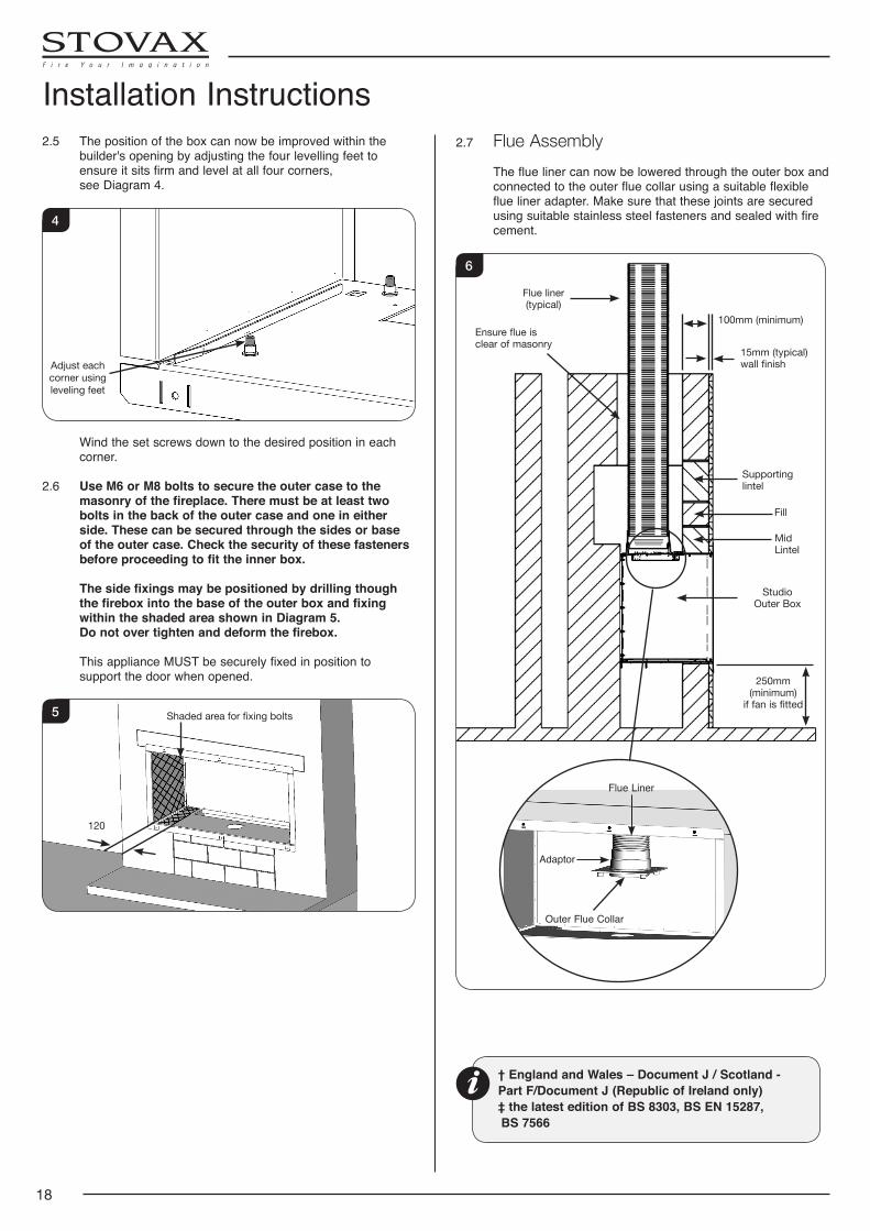
Installation Instructions2.5 The position of the box can now be improved within the
builder's opening by adjusting the four levelling feet to ensure it sits firm and level at all four corners,
see Diagram 4.
Adjust each corner using leveling feet
4
Wind the set screws down to the desired position in each corner.
2.6 Use M6 or M8 bolts to secure the outer case to the masonry of the fireplace. There must be at least two bolts in the back of the outer case and one in either side. These can be secured through the sides or base of the outer case. Check the security of these fasteners before proceeding to fit the inner box.
The side fixings may be positioned by drilling though the firebox into the base of the outer box and fixing within the shaded area shown in Diagram 5.
Do not over tighten and deform the firebox.
This appliance MUST be securely fixed in position to support the door when opened.
Shaded area for fixing bolts
120
5
† England and Wales – Document J / Scotland - Part F/Document J (Republic of Ireland only)‡ the latest edition of BS 8303, BS EN 15287,
BS 7566
2.7 Flue Assembly The flue liner can now be lowered through the outer box and
connected to the outer flue collar using a suitable flexible flue liner adapter. Make sure that these joints are secured using suitable stainless steel fasteners and sealed with fire cement.
Flue liner (typical)
Fill
250mm (minimum)
if fan is fitted
Studio Outer Box
Mid Lintel
Supporting lintel
Ensure flue is clear of masonry
15mm (typical) wall finish
100mm (minimum)
6
Outer Flue Collar
Flue Liner
Adaptor
19
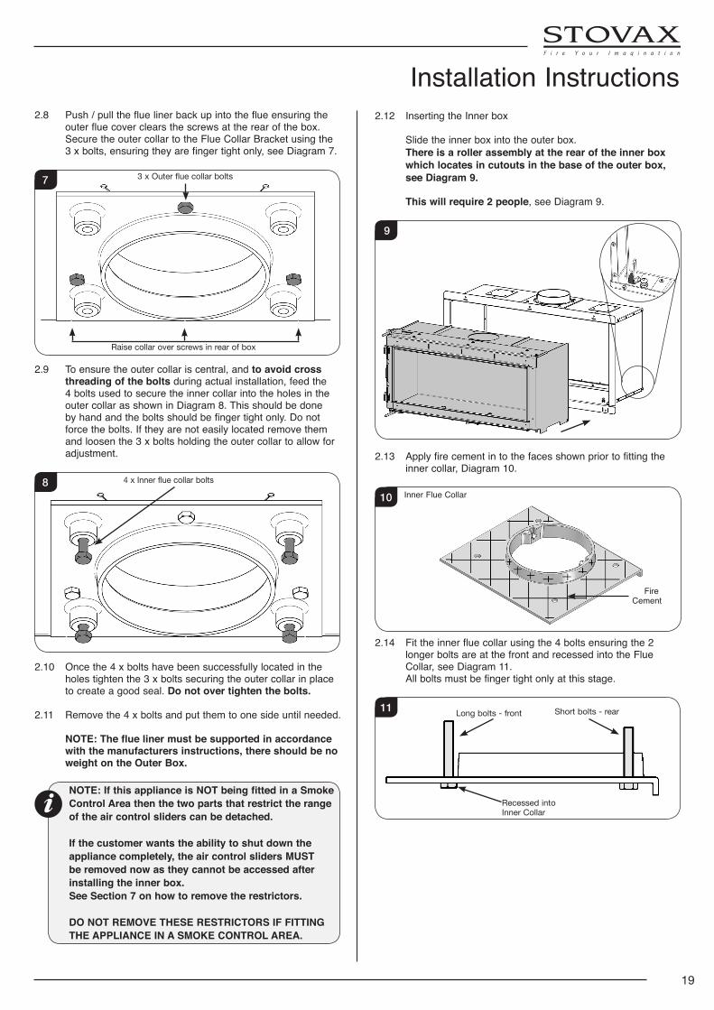
Installation Instructions2.8 Push / pull the flue liner back up into the flue ensuring the
outer flue cover clears the screws at the rear of the box. Secure the outer collar to the Flue Collar Bracket using the 3 x bolts, ensuring they are finger tight only, see Diagram 7.
3 x Outer flue collar bolts
Raise collar over screws in rear of box
7
2.9 To ensure the outer collar is central, and to avoid cross threading of the bolts during actual installation, feed the 4 bolts used to secure the inner collar into the holes in the outer collar as shown in Diagram 8. This should be done by hand and the bolts should be finger tight only. Do not force the bolts. If they are not easily located remove them and loosen the 3 x bolts holding the outer collar to allow for adjustment.
4 x Inner flue collar bolts8
2.10 Once the 4 x bolts have been successfully located in the holes tighten the 3 x bolts securing the outer collar in place to create a good seal. Do not over tighten the bolts.
2.11 Remove the 4 x bolts and put them to one side until needed.
NOTE: The flue liner must be supported in accordance with the manufacturers instructions, there should be no weight on the Outer Box.
NOTE: If this appliance is NOT being fitted in a Smoke Control Area then the two parts that restrict the range of the air control sliders can be detached.
If the customer wants the ability to shut down the appliance completely, the air control sliders MUST be removed now as they cannot be accessed after installing the inner box.See Section 7 on how to remove the restrictors.
DO NOT REMOVE THESE RESTRICTORS IF FITTING THE APPLIANCE IN A SMOKE CONTROL AREA.
2.12 Inserting the Inner box
Slide the inner box into the outer box. There is a roller assembly at the rear of the inner box
which locates in cutouts in the base of the outer box, see Diagram 9.
This will require 2 people, see Diagram 9.
9
2.13 Apply fire cement in to the faces shown prior to fitting the inner collar, Diagram 10.
Inner Flue Collar
Fire Cement
10
2.14 Fit the inner flue collar using the 4 bolts ensuring the 2 longer bolts are at the front and recessed into the Flue Collar, see Diagram 11.
All bolts must be finger tight only at this stage.
Recessed into Inner Collar
Long bolts - front Short bolts - rear11
20
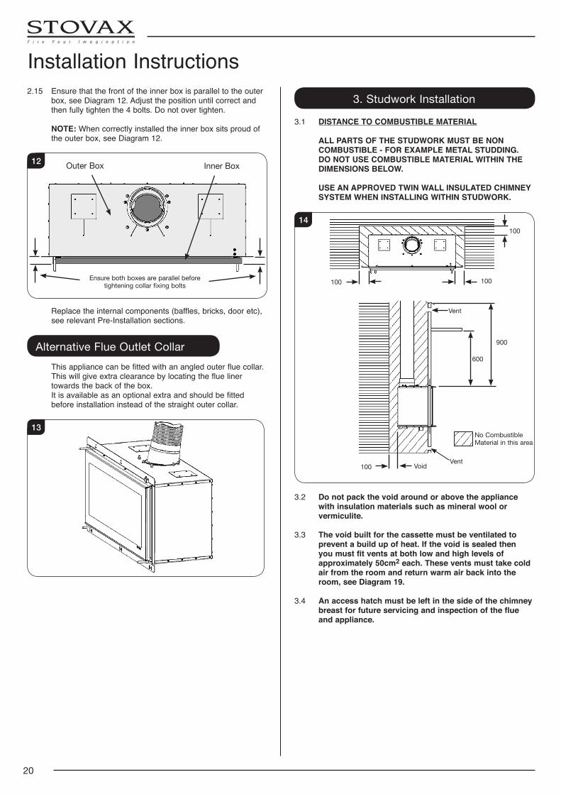
Installation Instructions2.15 Ensure that the front of the inner box is parallel to the outer
box, see Diagram 12. Adjust the position until correct and then fully tighten the 4 bolts. Do not over tighten.
NOTE: When correctly installed the inner box sits proud of the outer box, see Diagram 12.
Inner BoxOuter Box
Ensure both boxes are parallel before tightening collar fixing bolts
12
Replace the internal components (baffles, bricks, door etc), see relevant Pre-Installation sections.
Alternative Flue Outlet Collar This appliance can be fitted with an angled outer flue collar.
This will give extra clearance by locating the flue liner towards the back of the box.
It is available as an optional extra and should be fitted before installation instead of the straight outer collar.
13
3. Studwork Installation
3.1 DISTANCE TO COMBUSTIBLE MATERIAL
ALL PARTS OF THE STUDWORK MUST BE NON COMBUSTIBLE - FOR EXAMPLE METAL STUDDING.
DO NOT USE COMBUSTIBLE MATERIAL WITHIN THE DIMENSIONS BELOW.
USE AN APPROVED TWIN WALL INSULATED CHIMNEY SYSTEM WHEN INSTALLING WITHIN STUDWORK.
100
100
100
100
Vent
Vent
900
600
Void
No Combustible Material in this area
14
3.2 Do not pack the void around or above the appliance with insulation materials such as mineral wool or vermiculite.
3.3 The void built for the cassette must be ventilated to prevent a build up of heat. If the void is sealed then you must fit vents at both low and high levels of approximately 50cm2 each. These vents must take cold air from the room and return warm air back into the room, see Diagram 19.
3.4 An access hatch must be left in the side of the chimney breast for future servicing and inspection of the flue and appliance.
21
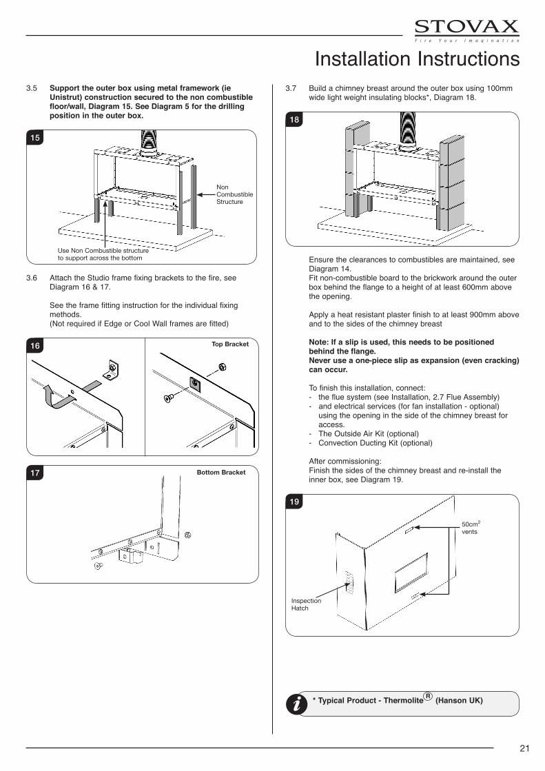
3.5 Support the outer box using metal framework (ie Unistrut) construction secured to the non combustible floor/wall, Diagram 15. See Diagram 5 for the drilling position in the outer box.
Non Combustible Structure
Use Non Combustible structure to support across the bottom
15
3.6 Attach the Studio frame fixing brackets to the fire, see Diagram 16 & 17.
See the frame fitting instruction for the individual fixing methods.
(Not required if Edge or Cool Wall frames are fitted)
16 Top Bracket
17 Bottom Bracket
3.7 Build a chimney breast around the outer box using 100mm wide light weight insulating blocks*, Diagram 18.
18
Ensure the clearances to combustibles are maintained, see Diagram 14.
Fit non-combustible board to the brickwork around the outer box behind the flange to a height of at least 600mm above the opening.
Apply a heat resistant plaster finish to at least 900mm above
and to the sides of the chimney breast Note: If a slip is used, this needs to be positioned
behind the flange. Never use a one-piece slip as expansion (even cracking)
can occur.
To finish this installation, connect: - the flue system (see Installation, 2.7 Flue Assembly) - and electrical services (for fan installation - optional)
using the opening in the side of the chimney breast for access.
- The Outside Air Kit (optional) - Convection Ducting Kit (optional)
After commissioning: Finish the sides of the chimney breast and re-install the
inner box, see Diagram 19.
50cm2 vents
Inspection Hatch
19
Installation Instructions
* Typical Product - Thermolite R (Hanson UK)
22
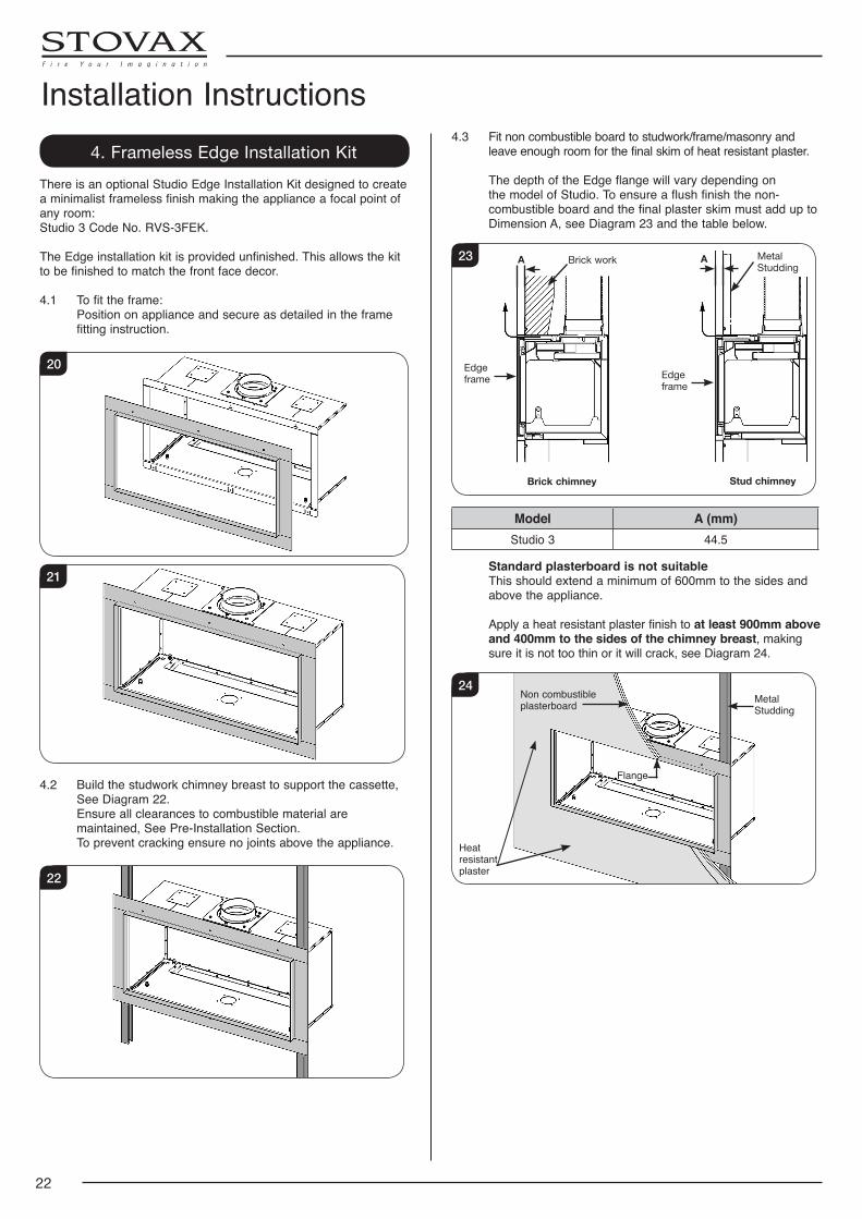
4. Frameless Edge Installation KitThere is an optional Studio Edge Installation Kit designed to create a minimalist frameless finish making the appliance a focal point of any room: Studio 3 Code No. RVS-3FEK.
The Edge installation kit is provided unfinished. This allows the kit to be finished to match the front face decor.
4.1 To fit the frame: Position on appliance and secure as detailed in the frame
fitting instruction.
20
21
4.2 Build the studwork chimney breast to support the cassette, See Diagram 22.
Ensure all clearances to combustible material are maintained, See Pre-Installation Section.
To prevent cracking ensure no joints above the appliance.
22
4.3 Fit non combustible board to studwork/frame/masonry and leave enough room for the final skim of heat resistant plaster.
The depth of the Edge flange will vary depending on the model of Studio. To ensure a flush finish the non-combustible board and the final plaster skim must add up to Dimension A, see Diagram 23 and the table below.
Metal Studding
AA Brick work
Brick chimney Stud chimney
Edge frame Edge
frame
23
Model A (mm)Studio 3 44.5
Standard plasterboard is not suitable This should extend a minimum of 600mm to the sides and
above the appliance.
Apply a heat resistant plaster finish to at least 900mm above and 400mm to the sides of the chimney breast, making sure it is not too thin or it will crack, see Diagram 24.
Heat resistant plaster
Metal Studding
Non combustible plasterboard
Flange
24
Installation Instructions
23
4.4 Allow for the connection of the following: - Electrical services (for fan installation) using the opening in
the side of the chimney breast for access. - The Outside Air Kit (optional) - Convection Ducting Kit (optional) - The flue system (see Installation, 2.7 Flue Assembly)
To finish this installation re-install the inner box.
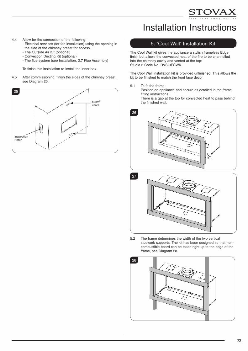
4.5 After commissioning, finish the sides of the chimney breast, see Diagram 25.
50cm2 vents
Inspection Hatch
25
5. 'Cool Wall' Installation KitThe Cool Wall kit gives the appliance a stylish frameless Edge finish but allows the convected heat of the fire to be channelled into the chimney cavity and vented at the top: Studio 3 Code No. RVS-3FCWK.
The Cool Wall installation kit is provided unfinished. This allows the kit to be finished to match the front face decor.
5.1 To fit the frame: Position on appliance and secure as detailed in the frame
fitting instructions. There is a gap at the top for convected heat to pass behind
the finished wall.
26
27
5.2 The frame determines the width of the two vertical studwork supports. The kit has been designed so that non-combustible board can be taken right up to the edge of the frame, see Diagram 28.
28
Installation Instructions
24
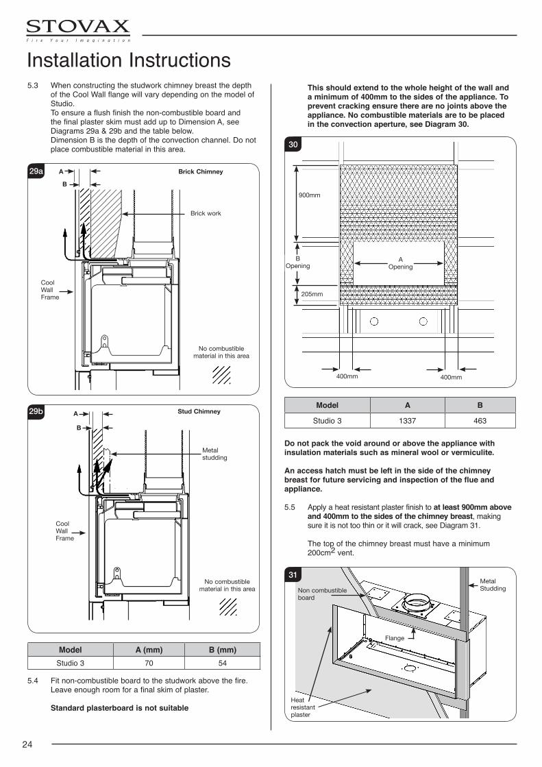
5.3 When constructing the studwork chimney breast the depth of the Cool Wall flange will vary depending on the model of Studio.
To ensure a flush finish the non-combustible board and the final plaster skim must add up to Dimension A, see Diagrams 29a & 29b and the table below.
Dimension B is the depth of the convection channel. Do not place combustible material in this area.
Cool Wall Frame
No combustible material in this area
Brick work
Brick ChimneyA
B
29a
Cool Wall Frame
No combustible material in this area
Metal studding
Stud ChimneyA
B
29b
Model A (mm) B (mm)Studio 3 70 54
5.4 Fit non-combustible board to the studwork above the fire. Leave enough room for a final skim of plaster.
Standard plasterboard is not suitable
This should extend to the whole height of the wall and a minimum of 400mm to the sides of the appliance. To prevent cracking ensure there are no joints above the appliance. No combustible materials are to be placed in the convection aperture, see Diagram 30.
900mm
205mm
400mm 400mm
BOpening
AOpening
30
Model A B
Studio 3 1337 463
Do not pack the void around or above the appliance with insulation materials such as mineral wool or vermiculite.
An access hatch must be left in the side of the chimney breast for future servicing and inspection of the flue and appliance.
5.5 Apply a heat resistant plaster finish to at least 900mm above and 400mm to the sides of the chimney breast, making sure it is not too thin or it will crack, see Diagram 31.
The top of the chimney breast must have a minimum 200cm2 vent.
Heat resistant plaster
Non combustible board
Metal Studding
Flange
31
Installation Instructions
25
Installation Instructions5.6 Fit plasterboard to the remaining chimney breast front.
5.7 Allow for the connection of the following: - Electrical services (for fan installation) using the opening in
the side of the chimney breast for access. - The Outside Air Kit (optional) - Convection Ducting Kit (optional) - The flue system (see Installation, 2.7 Flue Assembly)
5.8 Connect the flue system and electrical services if fan is to be fitted using the opening in the side of the chimney breast for access.
5.9 Apply a heat resistant plaster finish to at least 900mm above and 400mm to the sides of the chimney breast.
NOTE: If this appliance is NOT being fitted in a Smoke Control Area then the two parts that restrict the range of the air control sliders can be detached.
If the customer wants the ability to shut down the appliance completely, the air control sliders MUST be removed now as they cannot be accessed after installing the inner box.See Section 7 on how to remove the restrictors.
DO NOT REMOVE THESE RESTRICTORS IF FITTING THE APPLIANCE IN A SMOKE CONTROL AREA.
To finish this installation re-install the inner box.
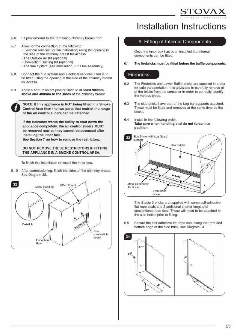
5.10 After commissioning, finish the sides of the chimney breast, See Diagram 32.
Detail A
A
200cm2 ventMetal studding
Non combustible board
Inspection Hatch
32
6. Fitting of Internal Components
Once the inner box has been installed the internal components can be fitted.
6.1 The firebricks must be fitted before the baffle components.
Firebricks
6.2 The Firebricks and Lower Baffle bricks are supplied in a box for safe transportation. It is advisable to carefully remove all of the bricks from the container in order to correctly identify the various types.
6.3 The side bricks have part of the Log bar supports attached. These must be fitted and removed at the same time as the bricks.
6.4 Install in the following order. Take care when handling and do not force into
position.
Side Bricks with Log Guard support
Rear Bricks
Front base bricks
Metal Secondary Air Bricks
33
The Studio 3 bricks are supplied with some self-adhesive flat rope seals and 2 additional shorter lengths of conventional rope seal. These will need to be attached to the side bricks prior to fitting.
6.5 Secure the self-adhesive flat rope seal along the front and bottom edge of the side brick, see Diagram 34.
34
26
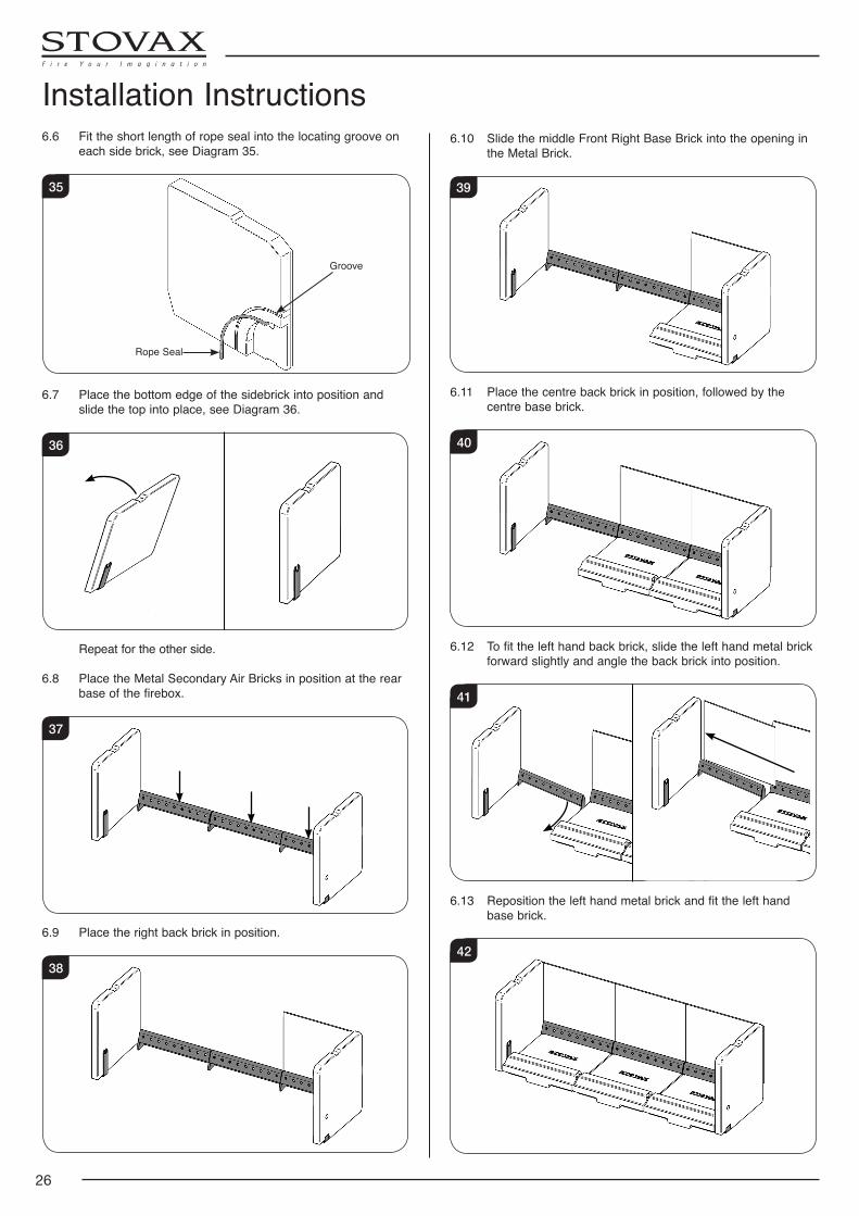
6.6 Fit the short length of rope seal into the locating groove on each side brick, see Diagram 35.
35
Rope Seal
Groove
6.7 Place the bottom edge of the sidebrick into position and slide the top into place, see Diagram 36.
36
Repeat for the other side.
6.8 Place the Metal Secondary Air Bricks in position at the rear base of the firebox.
37
6.9 Place the right back brick in position.
38
6.10 Slide the middle Front Right Base Brick into the opening in the Metal Brick.
39
6.11 Place the centre back brick in position, followed by the centre base brick.
40
6.12 To fit the left hand back brick, slide the left hand metal brick forward slightly and angle the back brick into position.
41
6.13 Reposition the left hand metal brick and fit the left hand base brick.
42
Installation Instructions
27
Installation Instructions6.14 Removal is the reverse of this procedure. Allow the appliance to cool fully before removing baffle
system.
Do not modify firebricks. Do not operate with firebricks removed.
Upper Metal Baffle The appliance is fitted with baffles in the top of the firebox to
maintain efficient combustion. Studio 3 has 3 baffles.
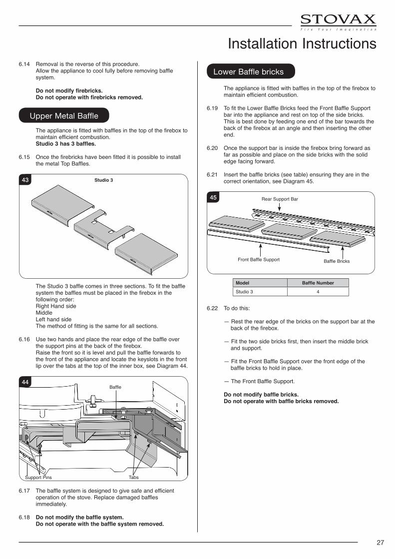
6.15 Once the firebricks have been fitted it is possible to install the metal Top Baffles.
Studio 343
The Studio 3 baffle comes in three sections. To fit the baffle system the baffles must be placed in the firebox in the following order:
Right Hand side Middle Left hand side The method of fitting is the same for all sections.
6.16 Use two hands and place the rear edge of the baffle over the support pins at the back of the firebox.
Raise the front so it is level and pull the baffle forwards to the front of the appliance and locate the keyslots in the front lip over the tabs at the top of the inner box, see Diagram 44.
44
Support Pins Tabs
Baffle
6.17 The baffle system is designed to give safe and efficient operation of the stove. Replace damaged baffles immediately.
6.18 Do not modify the baffle system. Do not operate with the baffle system removed.
Lower Baffle bricks
The appliance is fitted with baffles in the top of the firebox to maintain efficient combustion.
6.19 To fit the Lower Baffle Bricks feed the Front Baffle Support bar into the appliance and rest on top of the side bricks.
This is best done by feeding one end of the bar towards the back of the firebox at an angle and then inserting the other end.
6.20 Once the support bar is inside the firebox bring forward as far as possible and place on the side bricks with the solid edge facing forward.
6.21 Insert the baffle bricks (see table) ensuring they are in the correct orientation, see Diagram 45.
45 Rear Support Bar
Front Baffle Support Baffle Bricks
Model Baffle Number
Studio 3 4
6.22 To do this: — Rest the rear edge of the bricks on the support bar at the
back of the firebox.
— Fit the two side bricks first, then insert the middle brick and support.
— Fit the Front Baffle Support over the front edge of the baffle bricks to hold in place.
— The Front Baffle Support.
Do not modify baffle bricks. Do not operate with baffle bricks removed.
28
Log Guard
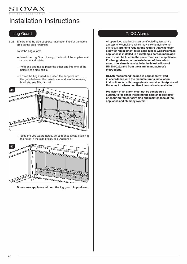
6.23 Ensure that the side supports have been fitted at the same time as the side Firebricks
To fit the Log guard:
— Insert the Log Guard through the front of the appliance at an angle and rotate.
— With one end raised place the other end into one of the holes in the side bricks.
— Lower the Log Guard and insert the supports into
the gaps between the base bricks and into the retaining brackets, see Diagram 46.
46
— Slide the Log Guard across so both ends locate evenly in the holes in the side bricks, see Diagram 47.
47
Do not use appliance without the log guard in position.
Installation Instructions7. CO Alarms
Allopenfluedappliancescanbeaffectedbytemporaryatmospheric conditions which may allow fumes to enter the house. Building regulations require that whenever a new or replacement fixed solid fuel or wood/biomass appliance is installed in a dwelling a carbon monoxide alarm must be fitted in the same room as the appliance. Further guidance on the installation of the carbon monoxide alarm is available in the latest edition of
BS EN50292 and from the alarm manufacturer's instructions.
HETAS recommend the unit is permanently fixed in accordance with the manufacturer's installation instructions or with the guidance contained in Approved Document J where no other information is available.
Provision of an alarm must not be considered a substitute for either installing the appliance correctly or ensuring regular servicing and maintenance of the appliance and chimney system.
29
Commissioning
1.1 To commission: — Replace the internal components.
— Check the door alignment and catch operation and adjust if required (see Maintenance & Servicing, Sections 4 & 5).
— Check the soundness of door seals, castings and joints.
— Check the operation of the air controls.
1.2 Now carry out a final smoke draw test: — Warm the flue with a blowlamp, or similar, for about 10
minutes. — Place a smoke pellet on the centre of the grate, with the
air controls open. — Close the door. Smoke should now be drawn up the flue
and be seen to exit from the flue terminal. — Complete test with all doors and windows closed in the
room where the appliance is fitted.
— If there are any extractor fans in adjacent rooms the test must be repeated with the fans running on maximum and with interconnecting doors open.
— Check the effect of ceiling fans during the test.
If the test fails, re-check the suitability of the flue system and ventilation. An inadequate air supply to the room is potentially dangerous.
— Light the appliance and slowly increase the temperature. — Ensure no combustion products enter the room.
— Open the main fire door when the appliance reaches operating temperature and carry out a spillage test with
a smoke match or pellet around the door opening.
1.3 If excessive spillage occurs allow the appliance to cool and re-check the flue system and ventilation.
1.4 Finally: — Explain to the user the correct operation of the
appliance, use of the controls and the importance of only using suitable fuels in order to reduce smoke emissions - particularly if they live in a Smoke Control Area.
— Ensure that a CO alarm has been fitted and make the user aware of its operation and importance, referring them to the Warning section on page 5 of the User Instructions.
— Explain the cleaning and routine maintenance requirements.
— Explain the requirement to use a suitable fireguard when children, elderly or infirm persons are near the appliance.
— Record retailer/supplier and installer details in Appliance Commissioning Checklist (page 3, Instructions for Use).
— Record serial number in Appliance Commissioning Checklist (page 3, Instructions for Use).
This number is required when ordering spare parts and
making warranty claims.
— Give this instruction manual to the customer.
Commissioning
30
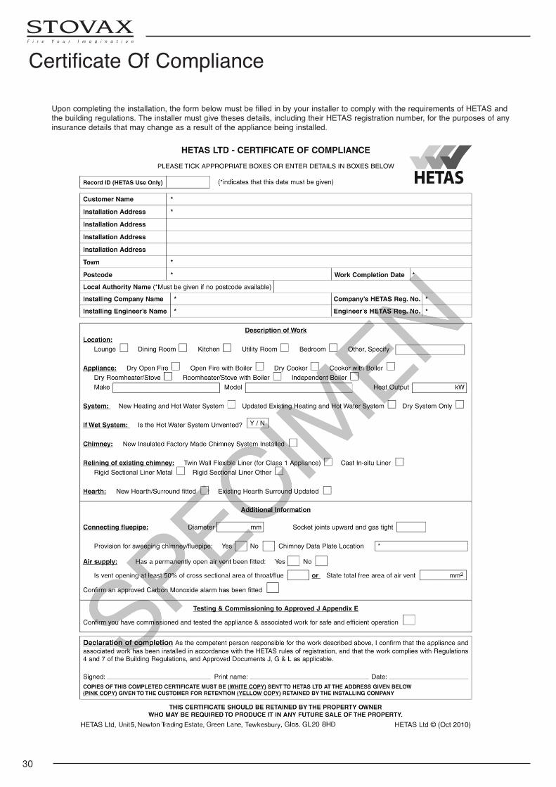
Certificate Of Compliance
Upon completing the installation, the form below must be filled in by your installer to comply with the requirements of HETAS and the building regulations. The installer must give theses details, including their HETAS registration number, for the purposes of any insurance details that may change as a result of the appliance being installed.
31
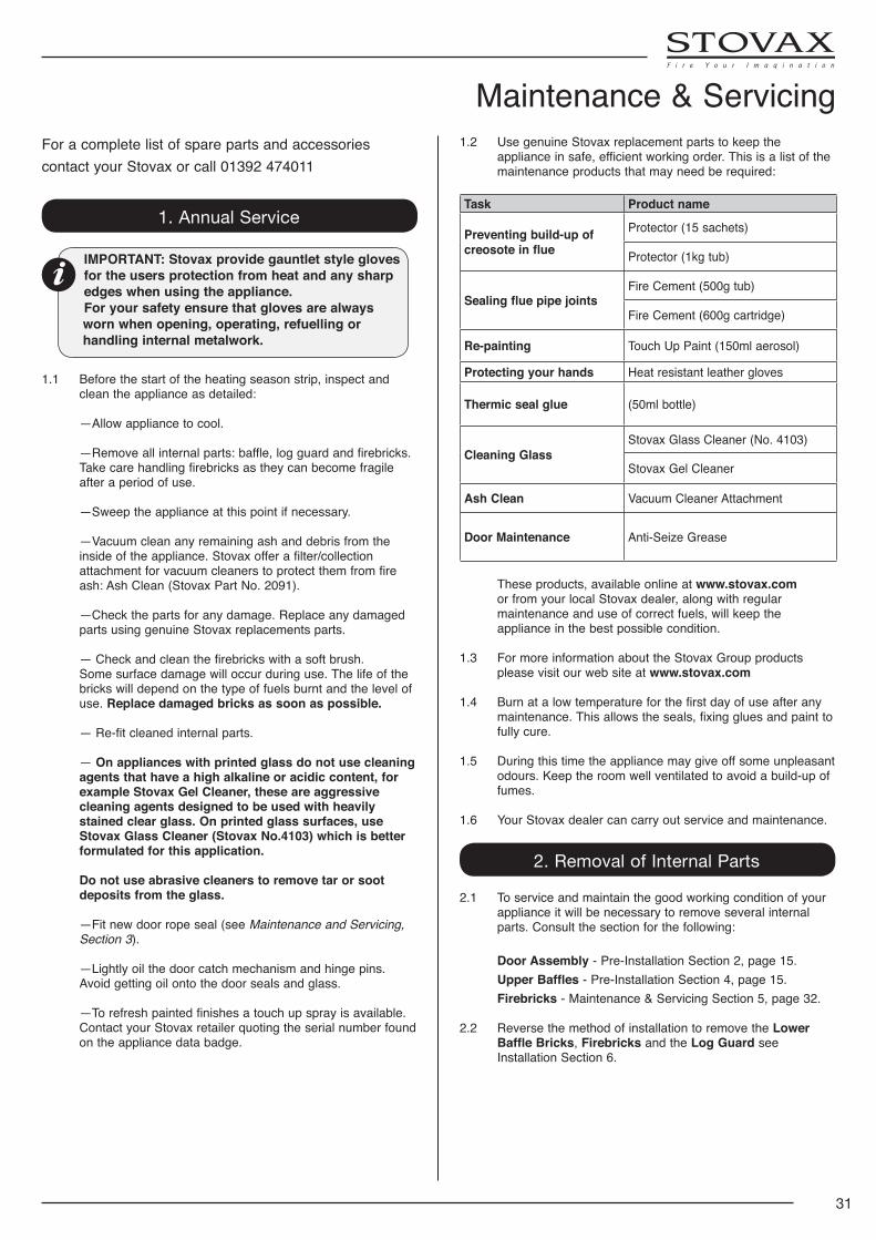
For a complete list of spare parts and accessories contact your Stovax or call 01392 474011
1. Annual Service
IMPORTANT: Stovax provide gauntlet style gloves for the users protection from heat and any sharp edges when using the appliance.For your safety ensure that gloves are always worn when opening, operating, refuelling or handling internal metalwork.
1.1 Before the start of the heating season strip, inspect and clean the appliance as detailed:
—Allow appliance to cool. —Remove all internal parts: baffle, log guard and firebricks.
Take care handling firebricks as they can become fragile after a period of use.
—Sweep the appliance at this point if necessary.
—Vacuum clean any remaining ash and debris from the inside of the appliance. Stovax offer a filter/collection attachment for vacuum cleaners to protect them from fire ash: Ash Clean (Stovax Part No. 2091).
—Check the parts for any damage. Replace any damaged parts using genuine Stovax replacements parts.
— Check and clean the firebricks with a soft brush. Some surface damage will occur during use. The life of the
bricks will depend on the type of fuels burnt and the level of use. Replace damaged bricks as soon as possible.
— Re-fit cleaned internal parts.
— On appliances with printed glass do not use cleaning agents that have a high alkaline or acidic content, for example Stovax Gel Cleaner, these are aggressive cleaning agents designed to be used with heavily stained clear glass. On printed glass surfaces, use Stovax Glass Cleaner (Stovax No.4103) which is better formulated for this application.
Do not use abrasive cleaners to remove tar or soot deposits from the glass.
—Fit new door rope seal (see Maintenance and Servicing, Section 3).
—Lightly oil the door catch mechanism and hinge pins. Avoid getting oil onto the door seals and glass.
—Torefreshpaintedfinishesatouchupsprayisavailable.Contact your Stovax retailer quoting the serial number found on the appliance data badge.
1.2 Use genuine Stovax replacement parts to keep the appliance in safe, efficient working order. This is a list of the maintenance products that may need be required:
Task Product name
Preventing build-up of creosote in flue
Protector (15 sachets)
Protector (1kg tub)
Sealing flue pipe jointsFire Cement (500g tub)
Fire Cement (600g cartridge)
Re-painting Touch Up Paint (150ml aerosol)
Protecting your hands Heat resistant leather gloves
Thermic seal glue (50ml bottle)
Cleaning GlassStovax Glass Cleaner (No. 4103)
Stovax Gel Cleaner
Ash Clean Vacuum Cleaner Attachment
Door Maintenance Anti-Seize Grease
These products, available online at www.stovax.com or from your local Stovax dealer, along with regular maintenance and use of correct fuels, will keep the appliance in the best possible condition.
1.3 For more information about the Stovax Group products please visit our web site at www.stovax.com
1.4 Burn at a low temperature for the first day of use after any maintenance. This allows the seals, fixing glues and paint to fully cure.
1.5 During this time the appliance may give off some unpleasant odours. Keep the room well ventilated to avoid a build-up of fumes.
1.6 Your Stovax dealer can carry out service and maintenance.
2. Removal of Internal Parts
2.1 To service and maintain the good working condition of your appliance it will be necessary to remove several internal parts. Consult the section for the following:
Door Assembly - Pre-Installation Section 2, page 15. Upper Baffles - Pre-Installation Section 4, page 15. Firebricks - Maintenance & Servicing Section 5, page 32.
2.2 Reverse the method of installation to remove the Lower Baffle Bricks, Firebricks and the Log Guard see Installation Section 6.
Maintenance & Servicing
32
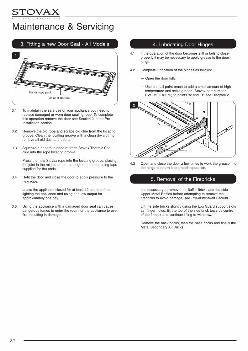
Maintenance & Servicing3. Fitting a new Door Seal - All Models
Joint at Bottom
Handy rope pack
1
3.1 To maintain the safe use of your appliance you need to replace damaged or worn door sealing rope. To complete this operation remove the door see Section 2 in the Pre-Installation section.
3.2 Remove the old rope and scrape old glue from the locating groove. Clean the locating groove with a clean dry cloth to remove all old dust and debris.
3.3 Squeeze a generous bead of fresh Stovax Thermic Seal glue into the rope locating groove.
Press the new Stovax rope into the locating groove, placing the joint in the middle of the top edge of the door using tape supplied for the ends.
3.4 Refit the door and close the door to apply pressure to the new rope.
Leave the appliance closed for at least 12 hours before lighting the appliance and using at a low output for approximately one day.
3.5 Using the appliance with a damaged door seal can cause dangerous fumes to enter the room, or the appliance to over fire, resulting in damage.
4. Lubricating Door Hinges4.1 If the operation of the door becomes stiff or fails to close
properly it may be necessary to apply grease to the door hinge.
4.2 Complete lubrication of the hinges as follows:
— Open the door fully.
— Use a small paint brush to add a small amount of high temperature anti-seize grease (Stovax part number - RVS-MEC10275) to points 'A' and 'B', see Diagram 2.
A
B
2
4.3 Open and close the door a few times to work the grease into the hinge to return it to smooth operation.
5. Removal of the Firebricks
It is necessary to remove the Baffle Bricks and the side Upper Metal Baffles before attempting to remove the firebricks to avoid damage, see Pre-Installation Section.
Lift the side bricks slightly using the Log Guard support slots as finger holds; tilt the top of the side brick towards centre of the firebox and continue lifting to withdraw.
Remove the back bricks, then the base bricks and finally the Metal Secondary Air Bricks.
33
Technical Appendix - Technical AppendixLegal Requirements
Before installation and/or use of this appliance please read these instructions carefully to ensure that all requirements are fully understood.
The appliance must be fitted by a registered installer*, or approved by your local building control officer.
It is very important to understand the requirements of the national Building Regulations† and standards‡, along with any local regulations and working practices that may apply. Should any conflict occur between these instructions and these regulations then the regulations must apply.
Your local Building Control Office can advise regarding the requirements of the regulations.
Works must be carried out with care to meet the requirements of Health and Safety‡ and comply with the Health and Safety rules**, and any new regulations introduced during the lifetime of these instructions. Particular attention should be drawn to:
—Handling: The appliance is heavy. Adequate facilities must be available for loading, unloading and on site handling.
—Fire Cement: Some fire cement is caustic and must not come into contact with the skin. Protective gloves must be worn. Wash hands thoroughly with plenty of water after contact with skin.
—Asbestos: This appliance contains no asbestos. If there is the possibility of disturbing any asbestos in the course
of installation seek specialist guidance and use appropriate equipment.
—Metal Parts: Take care when installing or servicing the stove to avoid personal injury.
A faulty installation can cause danger to the inhabitants and structure of the building.
For users of this appliance:Your building insurance company may require you to inform them that a new heating appliance has been installed on your property. Check that your cover is still valid after installing the appliance.
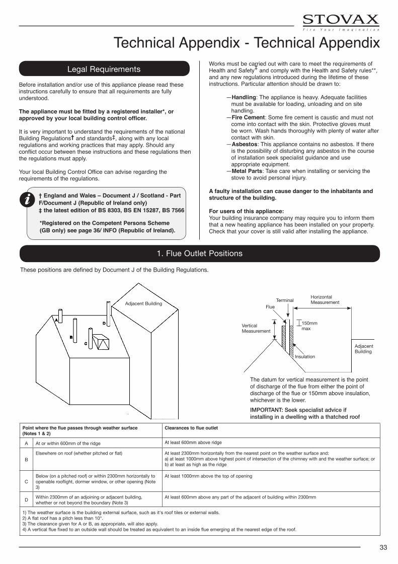
1. Flue Outlet Positions
150mm maxVertical
Measurement
Terminal
Insulation
Flue
Horizontal Measurement
Adjacent Building
The datum for vertical measurement is the point of discharge of the flue from either the point of discharge of the flue or 150mm above insulation, whichever is the lower.IMPORTANT: Seek specialist advice if installing in a dwelling with a thatched roof
These positions are defined by Document J of the Building Regulations.
Adjacent Building
Point where the flue passes through weather surface (Notes 1 & 2)
Clearances to flue outlet
A At or within 600mm of the ridge At least 600mm above ridge
BElsewhere on roof (whether pitched or flat) At least 2300mm horizontally from the nearest point on the weather surface and:
a) at least 1000mm above highest point of intersection of the chimney with and the weather surface; orb) at least as high as the ridge
CBelow (on a pitched roof) or within 2300mm horizontally to openable rooflight, dormer window, or other opening (Note 3)
At least 1000mm above the top of opening
D Within 2300mm of an adjoining or adjacent building, whether or not beyond the boundary (Note 3)
At least 600mm above any part of the adjacent of building within 2300mm
1) The weather surface is the building external surface, such as it's roof tiles or external walls.2) A flat roof has a pitch less than 10°.3) The clearance given for A or B, as appropriate, will also apply.4) A vertical flue fixed to an outside wall should be treated as equivalent to an inside flue emerging at the nearest edge of the roof.
† England and Wales – Document J / Scotland - Part F/Document J (Republic of Ireland only)‡ the latest edition of BS 8303, BS EN 15287, BS 7566
*Registered on the Competent Persons Scheme (GB only) see page 36/ INFO (Republic of Ireland).
34
Technical Appendix - Flues2. Flue or Chimney
2.1 The flue or chimney system must be in good condition. It must be inspected by a competent person and passed for
use with the appliance before installation.
Products of combustion entering the room can cause serious health risks.
2.2 The following must be checked:
— The construction of the masonry chimneys, flue block chimneys and connecting flue pipe system must meet the requirements of the Building Regulations†.
— A flexible flue liner system can be used if certified for use with solid fuel systems and installation complies with manufacturer’sinstructionsandBuildingRegulations. The flue liner must be replaced when an appliance is replaced, unless proven to be recently installed and in good condition.
— If it is necessary to fit a register plate it must conform to the Building Regulations†. — The minimum height of the flue or chimney must be 4.5m from the hearth to the top of the flue, with no horizontal sections and a maximum of 4 bends. Bends must have angles of less than 45 degrees from the vertical.
—There should be at least 600mm of vertical flue pipe above the appliance before any bends are introduced.
— Ensure the connecting flue pipe is kept a suitable distance from any combustible material and does not form part of the supporting structure of the building.
— The installer must ensure the flue pipe diameter is not less than the diameter of the outlet of the appliance and does not narrow to less than the size of the outlet at any point in the system.
— Make provision to remove the appliance without the need to dismantle the chimney.
— Any existing flue must be confirmed as suitable for the new intended use as defined in the Building Regulations.
— The flue or chimney systems must be inspected and swept to confirm the system is structurally sound and free from obstructions.
— If the chimney is believed to have previously served an open fire it must be swept a second time within a month of regular use after installation to clear any soot falls that may have occurred due to difference in combustion levels.
— The flue exit from the building must comply with local building control rules†.
—Chimney heights and/or separations may need to be increased in particular cases where wind exposure, surrounding tall buildings, high trees or high ground could have adverse effects on flue draught.
— Do not connect or share the flue or chimney system with another heating appliance.
2.3 Do not connect to systems containing large voids or spaces over 230mm square.
2.4 Suitable access must be provided to enable the collection and removal of debris.
2.5 The flue must be swept and inspected when the appliance is installed.
Flue Draught
The flue draught must be checked with all windows and doors closed and any extraction fans in this, or adjoining rooms, running at maximum speed (see Installation Checklist for ventilation requirements).
Twin Wall Flue System
If this appliance is to be used in conjunction with a twin wall flue system then Stovax recommend the use of their Professional XQ range. Details of this product are available from your Stovax retailer.
In the U.K: *BS EN 15287-1, and the requirements of Building
Regulations
**This should be done by a NACS registered (UK only)/INFO registered (Eire only) chimney sweep, who will issue you with a certificate.
† Building Regulations Document J
Flue Plate: Where a hearth, fireplace, flue or chimney is
provided or extended (including cases where a flue is provided as part of refurbishment work), information essential to the correct appliance and use of these should be permanently posted in the building, to meet Requirement J4 of the Building Regulations (England and Wales), F3.12 (Scotland).
Additional: A new factory made system that complies to EN
1856; Part 1 can be used providing installation is to the requirements of:
i) BS 7566 Parts 1 -4 ii) the manufacturer's instructions iii) Building Regulations.
For a guide containing information on Chimneys and Flues contact:
The British Flue & Chimney Manufacturers’ Association,
FETA 2 Waltham Court Milley Lane Hare Hatch Reading Berkshire RG10 9TH
Tel: 0118 9403416 e-mail: [email protected]
35
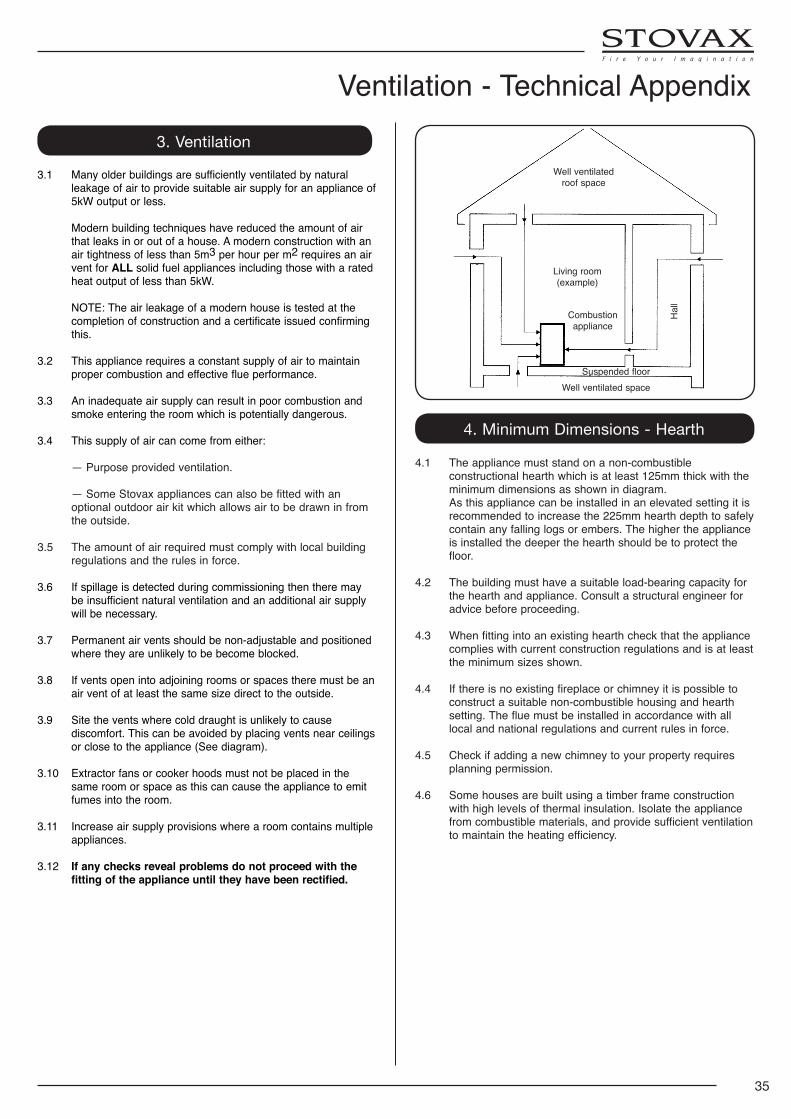
Ventilation - Technical Appendix 3. Ventilation
3.1 Many older buildings are sufficiently ventilated by natural leakage of air to provide suitable air supply for an appliance of 5kW output or less.
Modern building techniques have reduced the amount of air
that leaks in or out of a house. A modern construction with an air tightness of less than 5m3 per hour per m2 requires an air vent for ALL solid fuel appliances including those with a rated heat output of less than 5kW.
NOTE: The air leakage of a modern house is tested at the completion of construction and a certificate issued confirming this.
3.2 This appliance requires a constant supply of air to maintain proper combustion and effective flue performance.
3.3 An inadequate air supply can result in poor combustion and smoke entering the room which is potentially dangerous.
3.4 This supply of air can come from either:
— Purpose provided ventilation. — Some Stovax appliances can also be fitted with an
optional outdoor air kit which allows air to be drawn in from the outside.
3.5 The amount of air required must comply with local building
regulations and the rules in force.
3.6 If spillage is detected during commissioning then there may be insufficient natural ventilation and an additional air supply will be necessary.
3.7 Permanent air vents should be non-adjustable and positioned where they are unlikely to be become blocked.
3.8 If vents open into adjoining rooms or spaces there must be an air vent of at least the same size direct to the outside.
3.9 Site the vents where cold draught is unlikely to cause discomfort. This can be avoided by placing vents near ceilings or close to the appliance (See diagram).
3.10 Extractor fans or cooker hoods must not be placed in the same room or space as this can cause the appliance to emit fumes into the room.
3.11 Increase air supply provisions where a room contains multiple appliances.
3.12 If any checks reveal problems do not proceed with the fitting of the appliance until they have been rectified.
Well ventilated roof space
Living room (example)
Hal
l
Well ventilated spaceSuspended floor
Combustion appliance
4. Minimum Dimensions - Hearth
4.1 The appliance must stand on a non-combustible constructional hearth which is at least 125mm thick with the minimum dimensions as shown in diagram.
As this appliance can be installed in an elevated setting it is recommended to increase the 225mm hearth depth to safely contain any falling logs or embers. The higher the appliance is installed the deeper the hearth should be to protect the floor.
4.2 The building must have a suitable load-bearing capacity for the hearth and appliance. Consult a structural engineer for advice before proceeding.
4.3 When fitting into an existing hearth check that the appliance complies with current construction regulations and is at least the minimum sizes shown.
4.4 If there is no existing fireplace or chimney it is possible to construct a suitable non-combustible housing and hearth setting. The flue must be installed in accordance with all local and national regulations and current rules in force.
4.5 Check if adding a new chimney to your property requires planning permission.
4.6 Some houses are built using a timber frame construction with high levels of thermal insulation. Isolate the appliance from combustible materials, and provide sufficient ventilation to maintain the heating efficiency.
36
Technical Appendix5. Builders Opening
Many fireplace openings have a supporting lintel. Remove the covering plaster to identify it's position before starting any constructive work. Do not remove constructional lintels without making provision to support the remaining structure of the building. The appliance must not form any part of the supporting structure.
5.1 The chimney/flue must have a sealed connection to the appliance flue spigot.
5.2 The structure of the builders opening will reach high temperatures. Use insulating blockwork to reduce the heat transfer to the external walls.
5.3 Take care when finishing the chimney breast and surrounding area. The conducted and convected heat emitted by the appliance could be high enough to crack normal plaster. Use a high temperature plaster, or face the area with a suitable non combustible board avoiding any joints above the appliance. New plaster should be fully dried before the appliance is used, or cracking could occur.
If you are in any doubt about your ability to produce a safe opening contact your Stovax dealer for professional advice.*
6. Fire Surround Clearances
6.1 We recommend you obtain expert advice before proceeding with work of this nature.
6.2 Some finishes may discolour with heat and some lower quality products may distort, or crack, when in use.
If stone / granite / marble or any other natural material is used to construct the fire surround, or any part of it, provision should be made for expansion and movement of the parts due to heating and cooling.
If you are in any doubt about the installation requirements, or suitability of fire surrounds contact your Stovax dealer.
6.3 All fire surrounds should be suitable for use with solid fuel heating products.
7. Fitting Appliances On A Boat
7.1 If an appliance is to be fitted in a boat it must be done in accordance with the latest edition of BS 8511 (Code of Practice for the Installation of Solid Fuel Heating Appliances on Boats). The Code covers the design, installation and operation of solid fuel heating appliances that are suitable for fitting into inland waterway boats, and gives guidance on product selection, design considerations, installation requirements, inspection and testing, as well as maintenance and safe use tips.
7.2 Consideration should also be given to the requirements of the Boat Safety Scheme (BSS) to ensure the boat's insurance remains valid.
7.3 The appliance should only be installed by a competent person with experience of the latest edition of BS 8511 and the Boat Safety Scheme (BSS).
7.4 Secure the product to a suitably constructed non-combustible hearth.
7.5 All open flued appliances can be affected by temporary atmospheric conditions which may allow fumes to enter the boat. An electronic carbon monoxide detector conforming to the latest edition of BSEN50292 must be fitted and maintained.
7.6 Failure to safely install the appliance could endanger the boat and persons on board.
Organisations authorised to certify competence in the installation of domestic solid fuel appliances (Competent Persons Scheme):
APHC - Association of Plumbing and Heating Contractors (Certification) Ltd. www.aphc.co.uk
BESCA - Building Engineering Services Competence Accreditation Ltd. www.besca.org.uk
HETAS - Heating Equipment Testing and Approval Scheme Ltd. www.hetas.co.uk
NAPIT - National Association of Professional Inspectors and Testers Ltd. www.napit.org.uk
NICEIC - NICEIC Group Ltd. www.niceic.org.uk
HETAS Approved Chimney Sweeps:
NACS - The National Association of Chimney Sweeps www.chimneyworks.co.uk
APICS - The Association of Master Chimney Sweeps Ltd. www.apics.org The Guild of Master Chimney Sweeps - guildofmasterchimneysweeps.co.uk
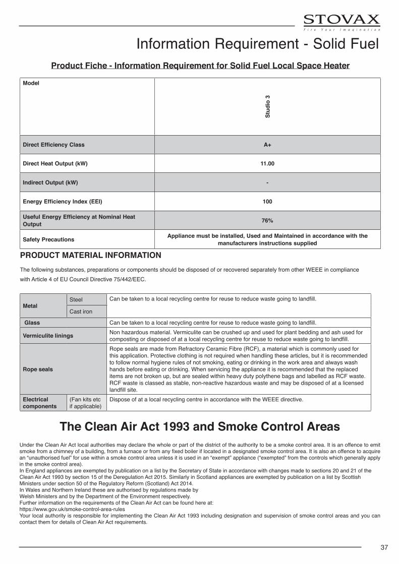
37
Model
Stud
io 3
Direct Efficiency Class A+
Direct Heat Output (kW) 11.00
Indirect Output (kW) -
Energy Efficiency Index (EEI) 100
Useful Energy Efficiency at Nominal Heat Output 76%
Safety Precautions Appliance must be installed, Used and Maintained in accordance with the manufacturers instructions supplied
Product Fiche - Information Requirement for Solid Fuel Local Space Heater
Information Requirement - Solid Fuel
The Clean Air Act 1993 and Smoke Control AreasUnder the Clean Air Act local authorities may declare the whole or part of the district of the authority to be a smoke control area. It is an offence to emit smokefromachimneyofabuilding,fromafurnaceorfromanyfixedboileriflocatedinadesignatedsmokecontrolarea.Itisalsoanoffencetoacquirean “unauthorised fuel” for use within a smoke control area unless it is used in an “exempt” appliance (“exempted” from the controls which generally apply in the smoke control area).In England appliances are exempted by publication on a list by the Secretary of State in accordance with changes made to sections 20 and 21 of theClean Air Act 1993 by section 15 of the Deregulation Act 2015. Similarly in Scotland appliances are exempted by publication on a list by ScottishMinisters under section 50 of the Regulatory Reform (Scotland) Act 2014.In Wales and Northern Ireland these are authorised by regulations made byWelsh Ministers and by the Department of the Environment respectively.Further information on the requirements of the Clean Air Act can be found here at:https://www.gov.uk/smoke-control-area-rulesYour local authority is responsible for implementing the Clean Air Act 1993 including designation and supervision of smoke control areas and you can contact them for details of Clean Air Act requirements.
PRODUCT MATERIAL INFORMATIONThe following substances, preparations or components should be disposed of or recovered separately from other WEEE in compliance with Article 4 of EU Council Directive 75/442/EEC.
MetalSteel Canbetakentoalocalrecyclingcentreforreusetoreducewastegoingtolandfill.
Cast iron
Glass Canbetakentoalocalrecyclingcentreforreusetoreducewastegoingtolandfill.
Vermiculite linings Non hazardous material. Vermiculite can be crushed up and used for plant bedding and ash used for compostingordisposedofatalocalrecyclingcentreforreusetoreducewastegoingtolandfill.
Rope seals
Rope seals are made from Refractory Ceramic Fibre (RCF), a material which is commonly used for this application. Protective clothing is not required when handling these articles, but it is recommended to follow normal hygiene rules of not smoking, eating or drinking in the work area and always wash hands before eating or drinking. When servicing the appliance it is recommended that the replaced items are not broken up, but are sealed within heavy duty polythene bags and labelled as RCF waste. RCF waste is classed as stable, non-reactive hazardous waste and may be disposed of at a licensed landfillsite.
Electrical components
(Fan kits etc if applicable)
Dispose of at a local recycling centre in accordance with the WEEE directive.
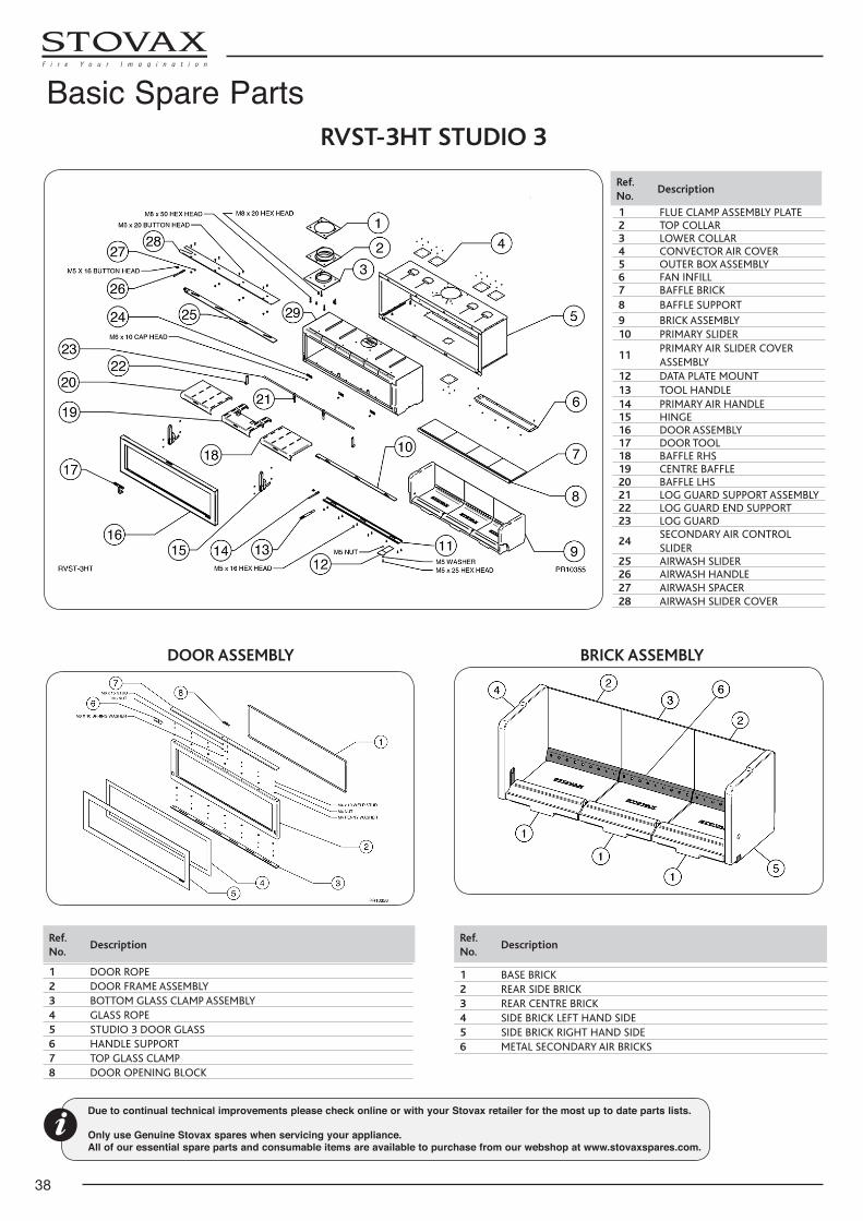
38
RVST-3HT STUDIO 3
Ref. No.
Description
1 FLUE CLAMP ASSEMBLY PLATE2 TOP COLLAR3 LOWER COLLAR4 CONVECTOR AIR COVER5 OUTER BOX ASSEMBLY6 FAN INFILL7 BAFFLE BRICK8 BAFFLE SUPPORT9 BRICK ASSEMBLY10 PRIMARY SLIDER
11PRIMARY AIR SLIDER COVER ASSEMBLY
12 DATA PLATE MOUNT13 TOOL HANDLE14 PRIMARY AIR HANDLE15 HINGE16 DOOR ASSEMBLY17 DOOR TOOL18 BAFFLE RHS19 CENTRE BAFFLE20 BAFFLE LHS21 LOG GUARD SUPPORT ASSEMBLY22 LOG GUARD END SUPPORT23 LOG GUARD
24SECONDARY AIR CONTROL SLIDER
25 AIRWASH SLIDER26 AIRWASH HANDLE27 AIRWASH SPACER28 AIRWASH SLIDER COVER
DOOR ASSEMBLY
Ref. No.
Description
1 DOOR ROPE2 DOOR FRAME ASSEMBLY3 BOTTOM GLASS CLAMP ASSEMBLY4 GLASS ROPE5 STUDIO 3 DOOR GLASS6 HANDLE SUPPORT7 TOP GLASS CLAMP8 DOOR OPENING BLOCK
BRICK ASSEMBLY
Ref. No.
Description
1 BASE BRICK2 REAR SIDE BRICK3 REAR CENTRE BRICK4 SIDE BRICK LEFT HAND SIDE5 SIDE BRICK RIGHT HAND SIDE6 METAL SECONDARY AIR BRICKS
Due to continual technical improvements please check online or with your Stovax retailer for the most up to date parts lists.
Only use Genuine Stovax spares when servicing your appliance. All of our essential spare parts and consumable items are available to purchase from our webshop at www.stovaxspares.com.
Basic Spare Parts
39
1ST SERVICEDate of Service:.................................................................Next Service Due:............................................................Signed:.............................................................................Dealer's Stamp/HETAS Registration Number
3RD SERVICEDate of Service:.................................................................Next Service Due:............................................................Signed:.............................................................................Dealer's Stamp/HETAS Registration Number
5TH SERVICEDate of Service:.................................................................Next Service Due:............................................................Signed:.............................................................................Dealer's Stamp/HETAS Registration Number
7TH SERVICEDate of Service:.................................................................Next Service Due:............................................................Signed:.............................................................................Dealer's Stamp/HETAS Registration Number
9TH SERVICEDate of Service:.................................................................Next Service Due:............................................................Signed:.............................................................................Dealer's Stamp/HETAS Registration Number
2ND SERVICEDate of Service:.................................................................Next Service Due:............................................................Signed:.............................................................................Dealer's Stamp/HETAS Registration Number
4TH SERVICEDate of Service:.................................................................Next Service Due:............................................................Signed:.............................................................................Dealer's Stamp/HETAS Registration Number
6TH SERVICEDate of Service:.................................................................Next Service Due:............................................................Signed:.............................................................................Dealer's Stamp/HETAS Registration Number
8TH SERVICEDate of Service:.................................................................Next Service Due:............................................................Signed:.............................................................................Dealer's Stamp/HETAS Registration Number
10TH SERVICEDate of Service:.................................................................Next Service Due:............................................................Signed:.............................................................................Dealer's Stamp/HETAS Registration Number
Service Records
Stovax Ltd, Falcon Road, Sowton Industrial Estate, Exeter, Devon, England EX2 7LF
Tel: (01392) 474011 Fax: (01392) 219932 E-mail: [email protected] www.stovax.com
E & O E
HETAS Approval
These appliances have been approved by HETAS as an intermittent operating appliance for burning dry seasoned wood logs only.
Recommended Fuels
Please note that HETAS Appliance Approval only covers the use of dry seasoned wood logs on these appliances. HETAS approval does not cover the use of other fuels either alone or mixed with the recommended fuels, nor does it cover instructions for the use of other fuels.
In order to avoid sub-standard fuel and optimum performance, wood fuelled appliances require fuel that complies with strict quality standards, purchase from a Woodsure certified producer.Woodsure is a not-for-profit organisation, striving to raise the quality of woodfuel in the industry. The Woodsure assurance means reliable wood fuel that fulfils manufacturer specifications and burns with optimum efficiency, without the risk of damage to your appliance.