Embed Size (px)
Citation preview
PR2482 Issue 4 (September 2019)
Instructions for Use, Installation & ServicingFor use in GB & IE (Great Britain & Republic of Ireland).
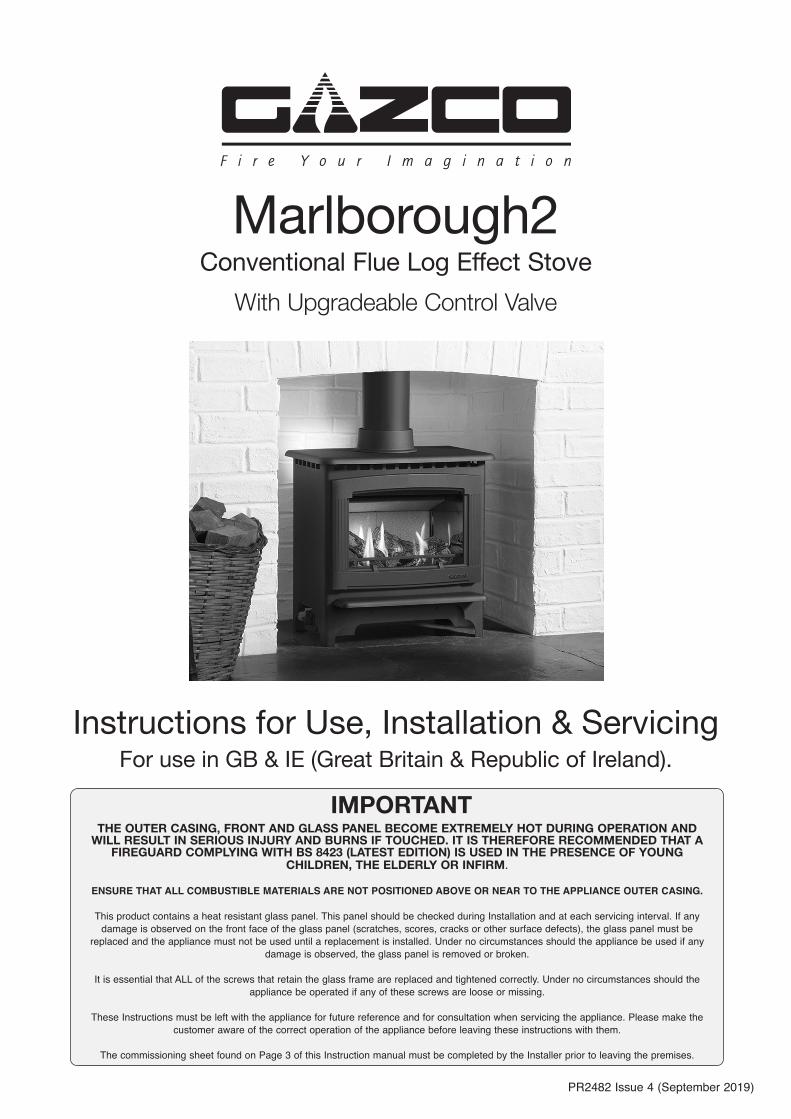
Marlborough2Conventional Flue Log Effect Stove
With Upgradeable Control Valve
THE OUTER CASING, FRONT AND GLASS PANEL BECOME EXTREMELY HOT DURING OPERATION AND WILL RESULT IN SERIOUS INJURY AND BURNS IF TOUCHED. IT IS THEREFORE RECOMMENDED THAT A
FIREGUARD COMPLYING WITH BS 8423 (LATEST EDITION) IS USED IN THE PRESENCE OF YOUNG CHILDREN, THE ELDERLY OR INFIRM.
ENSURE THAT ALL COMBUSTIBLE MATERIALS ARE NOT POSITIONED ABOVE OR NEAR TO THE APPLIANCE OUTER CASING.
This product contains a heat resistant glass panel. This panel should be checked during Installation and at each servicing interval. If any damage is observed on the front face of the glass panel (scratches, scores, cracks or other surface defects), the glass panel must be
replaced and the appliance must not be used until a replacement is installed. Under no circumstances should the appliance be used if any damage is observed, the glass panel is removed or broken.
It is essential that ALL of the screws that retain the glass frame are replaced and tightened correctly. Under no circumstances should the appliance be operated if any of these screws are loose or missing.
These Instructions must be left with the appliance for future reference and for consultation when servicing the appliance. Please make the customer aware of the correct operation of the appliance before leaving these instructions with them.
The commissioning sheet found on Page 3 of this Instruction manual must be completed by the Installer prior to leaving the premises.
IMPORTANT
2
Appliance Commissioning Checklist ......................3
User Instructions .......................................................4
Installation Instructions ..........................................11
Technical Specifications .......................................................... 11
Site Requirements .................................................................... 13
Installation ................................................................................15
Commissioning .........................................................................21
Servicing Instructions .............................................22
Fault Finding .............................................................................22
How to Replace Parts ..............................................................24
Spare Parts List ........................................................................ 32
Service Records .......................................................................35
Information Requirement - Gas Heaters ..................................36
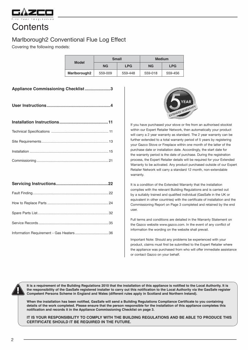
Marlborough2 Conventional Flue Log Effect
Contents
Covering the following models:
It is a requirement of the Building Regulations 2010 that the installation of this appliance is notified to the Local Authority. It is the responsibility of the GasSafe registered installer to carry out this notification to the Local Authority via the GasSafe register Competent Persons Scheme in England and Wales (different rules apply in Scotland and Northern Ireland).
When the installation has been notified, GasSafe will send a Building Regulations Compliance Certificate to you containing details of the work completed. Please ensure that the person responsible for the installation of this appliance completes this notification and records it in the Appliance Commissioning Checklist on page 3.
IT IS YOUR RESPONSIBILITY TO COMPLY WITH THE BUILDING REGULATIONS AND BE ABLE TO PRODUCE THIS CERTIFICATE SHOULD IT BE REQUIRED IN THE FUTURE.
If you have purchased your stove or fire from an authorised stockist within our Expert Retailer Network, then automatically your product will carry a 2 year warranty as standard. The 2 year warranty can be further extended to a total warranty period of 5 years by registering your Gazco Stove or Fireplace within one month of the latter of the purchase date or installation date. Accordingly, the start date for the warranty period is the date of purchase. During the registration process, the Expert Retailer details will be required for your Extended Warranty to be activated. Any product purchased outside of our Expert Retailer Network will carry a standard 12 month, non-extendable warranty.
It is a condition of the Extended Warranty that the installation complies with the relevant Building Regulations and is carried out by a suitably trained and qualified individual (GasSafe in the UK or equivalent in other countries) with the certificate of installation and the Commissioning Report on Page 3 completed and retained by the end user.
Full terms and conditions are detailed in the Warranty Statement on the Gazco website www.gazco.com. In the event of any conflict of information the wording on the website shall prevail.
Important Note: Should any problems be experienced with your product, claims must first be submitted to the Expert Retailer where the appliance was purchased from who will offer immediate assistance or contact Gazco on your behalf.
ModelSmall Medium
NG LPG NG LPG
Marlborough2 559-009 559-448 559-018 559-456
3
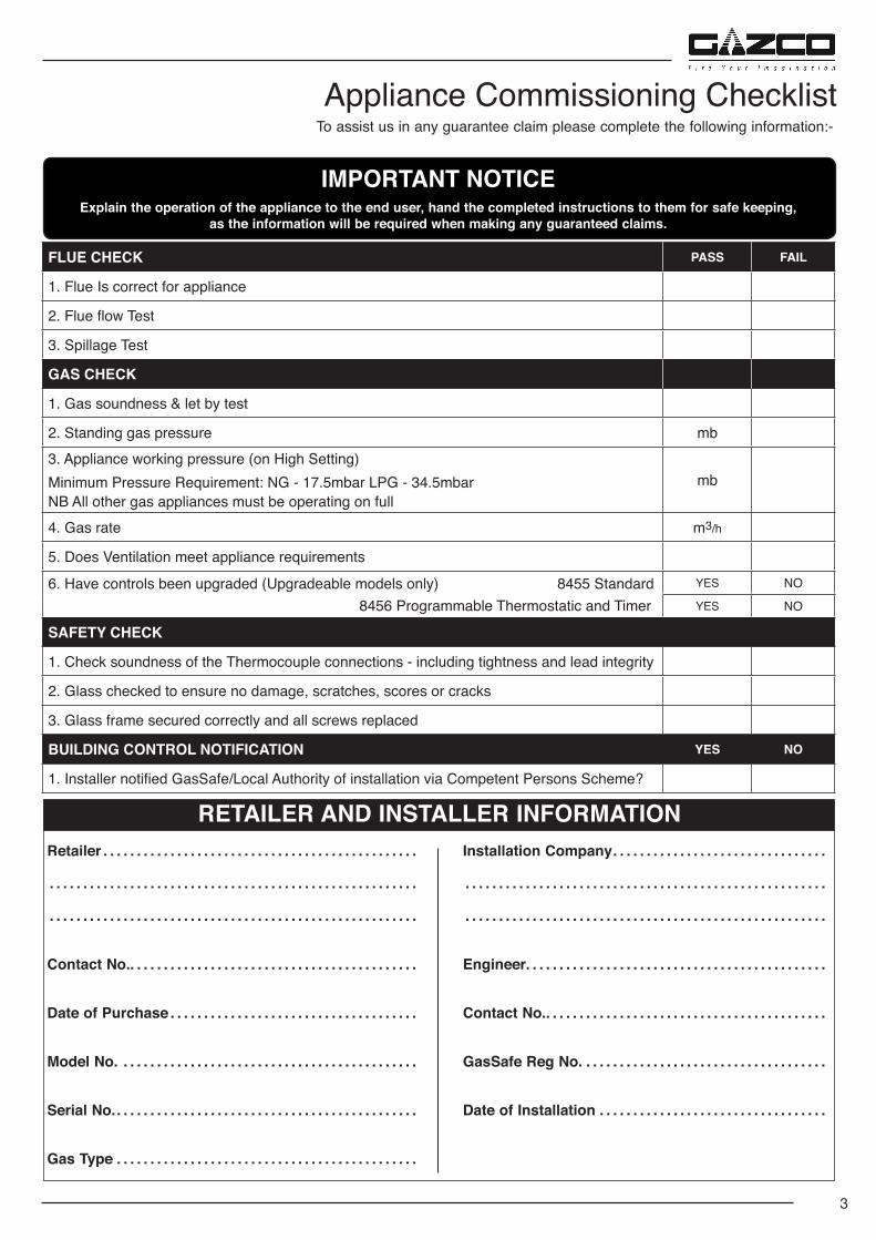
To assist us in any guarantee claim please complete the following information:-Appliance Commissioning Checklist
IMPORTANT NOTICEExplain the operation of the appliance to the end user, hand the completed instructions to them for safe keeping,
as the information will be required when making any guaranteed claims.
Retailer . . . . . . . . . . . . . . . . . . . . . . . . . . . . . . . . . . . . . . . . . . . . . . .
. . . . . . . . . . . . . . . . . . . . . . . . . . . . . . . . . . . . . . . . . . . . . . . . . . . . . . .
. . . . . . . . . . . . . . . . . . . . . . . . . . . . . . . . . . . . . . . . . . . . . . . . . . . . . . .
Contact No. . . . . . . . . . . . . . . . . . . . . . . . . . . . . . . . . . . . . . . . . . . .
Date of Purchase . . . . . . . . . . . . . . . . . . . . . . . . . . . . . . . . . . . . .
Model No. . . . . . . . . . . . . . . . . . . . . . . . . . . . . . . . . . . . . . . . . . . . .
Serial No. . . . . . . . . . . . . . . . . . . . . . . . . . . . . . . . . . . . . . . . . . . . . .
Gas Type . . . . . . . . . . . . . . . . . . . . . . . . . . . . . . . . . . . . . . . . . . . . .
Installation Company . . . . . . . . . . . . . . . . . . . . . . . . . . . . . . . .
. . . . . . . . . . . . . . . . . . . . . . . . . . . . . . . . . . . . . . . . . . . . . . . . . . . . . .
. . . . . . . . . . . . . . . . . . . . . . . . . . . . . . . . . . . . . . . . . . . . . . . . . . . . . .
Engineer. . . . . . . . . . . . . . . . . . . . . . . . . . . . . . . . . . . . . . . . . . . . .
Contact No. . . . . . . . . . . . . . . . . . . . . . . . . . . . . . . . . . . . . . . . . . .
GasSafe Reg No. . . . . . . . . . . . . . . . . . . . . . . . . . . . . . . . . . . . .
Date of Installation . . . . . . . . . . . . . . . . . . . . . . . . . . . . . . . . . .
RETAILER AND INSTALLER INFORMATION
FLUE CHECK PASS FAIL
1. Flue Is correct for appliance
2. Flue flow Test
3. Spillage Test
GAS CHECK
1. Gas soundness & let by test
2. Standing gas pressure mb3. Appliance working pressure (on High Setting)Minimum Pressure Requirement: NG - 17.5mbar LPG - 34.5mbarNB All other gas appliances must be operating on full
mb
4. Gas rate m3/h
5. Does Ventilation meet appliance requirements
6. Have controls been upgraded (Upgradeable models only) 8455 Standard 8456 Programmable Thermostatic and Timer
YES NO
YES NO
SAFETY CHECK
1. Check soundness of the Thermocouple connections - including tightness and lead integrity
2. Glass checked to ensure no damage, scratches, scores or cracks
3. Glass frame secured correctly and all screws replaced
BUILDING CONTROL NOTIFICATION YES NO
1. Installer notified GasSafe/Local Authority of installation via Competent Persons Scheme?
4
1.3 Do not place curtains above the appliance: You must have 300mm clearance between the appliance
and any curtains at either side.
1.4 The manufacturer considers the full outer casing of this appliance to be a working surface and it will become hot whilst in operation. A suitable guard is recommended to protect young children, the aged and the infirm.
1.5 No furnishings or other objects should be placed within 1 metre of the front of the appliance.
1.6 If a shelf is fitted, a distance of 225mm above the appliance is required.
1.7 Do not attempt to burn rubbish in this appliance.
1.8 This appliance must only be operated with the door secured firmly in position. If any cracks appear in the glass the appliance must not be used until the glass panel is replaced.
1.9 This product is guaranteed for 5 years from the date of installation, as set out in the terms and conditions of sale between Gazco and your local Gazco retailer. Please consult with your local Gazco retailer if you have any questions. In all correspondence always quote the Model Number and Serial Number.
2. Operating the Appliance
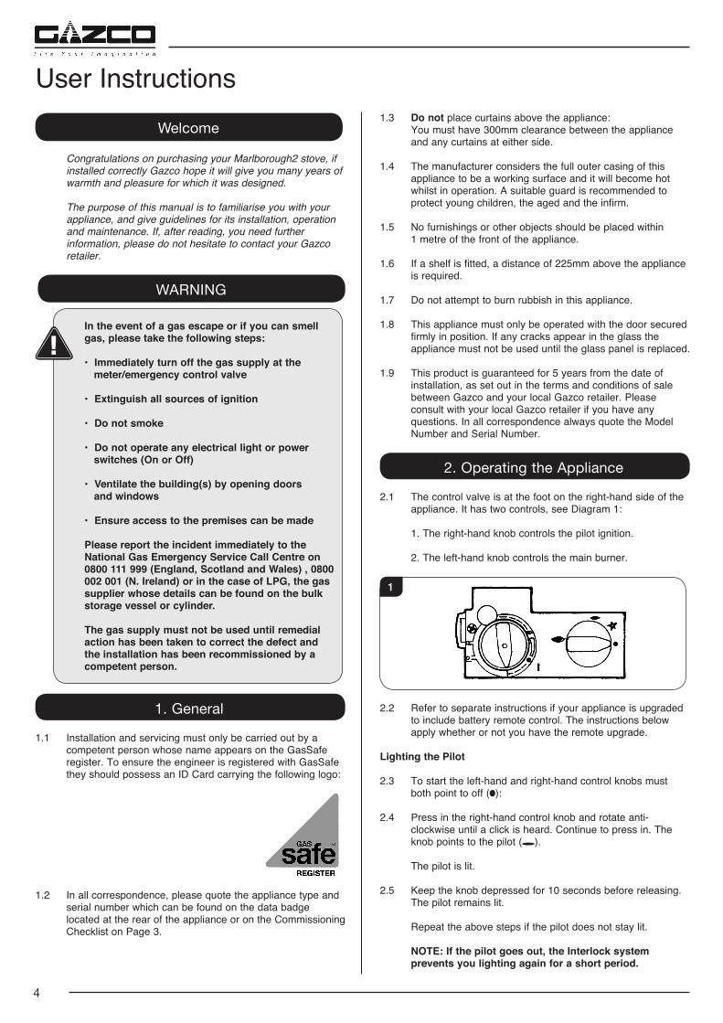
2.1 The control valve is at the foot on the right-hand side of the appliance. It has two controls, see Diagram 1:
1. The right-hand knob controls the pilot ignition.
2. The left-hand knob controls the main burner.
1
2.2 Refer to separate instructions if your appliance is upgraded to include battery remote control. The instructions below apply whether or not you have the remote upgrade.
Lighting the Pilot
2.3 To start the left-hand and right-hand control knobs must both point to off ( ):
2.4 Press in the right-hand control knob and rotate anti-clockwise until a click is heard. Continue to press in. The knob points to the pilot ( ).
The pilot is lit.
2.5 Keep the knob depressed for 10 seconds before releasing. The pilot remains lit.
Repeat the above steps if the pilot does not stay lit.
NOTE: If the pilot goes out, the Interlock system prevents you lighting again for a short period.
Welcome
Congratulations on purchasing your Marlborough2 stove, if installed correctly Gazco hope it will give you many years of warmth and pleasure for which it was designed.
The purpose of this manual is to familiarise you with your appliance, and give guidelines for its installation, operation and maintenance. If, after reading, you need further information, please do not hesitate to contact your Gazco retailer.
WARNING
In the event of a gas escape or if you can smell gas, please take the following steps:
• Immediately turn off the gas supply at the meter/emergency control valve
• Extinguish all sources of ignition
• Do not smoke
• Do not operate any electrical light or power switches (On or Off)
• Ventilate the building(s) by opening doors and windows
• Ensure access to the premises can be made
Please report the incident immediately to the National Gas Emergency Service Call Centre on 0800 111 999 (England, Scotland and Wales) , 0800 002 001 (N. Ireland) or in the case of LPG, the gas supplier whose details can be found on the bulk storage vessel or cylinder.
The gas supply must not be used until remedial action has been taken to correct the defect and the installation has been recommissioned by a competent person.
1. General
1.1 Installation and servicing must only be carried out by a competent person whose name appears on the GasSafe register. To ensure the engineer is registered with GasSafe they should possess an ID Card carrying the following logo:
1.2 In all correspondence, please quote the appliance type and serial number which can be found on the data badge located at the rear of the appliance or on the Commissioning Checklist on Page 3.
User Instructions
5
User Instructions2.6 If, after repeating the above steps the pilot does not light,
contact your Retailer or Installer.
2.7 Turn the right-hand knob to the left to main burner setting ( ).
Adjusting the Flame height
2.8 You can now adjust the flame height and temperature using the left-hand control knob.
2.9 Turn the left-hand knob anti-clockwise to increase the flame height.
2.10 Turn clockwise to decrease the height.
IMPORTANT: YELLOW FLAMES TYPICALLY APPEAR WHEN THE APPLIANCE HAS REACHED NORMAL OPERATING TEMPERATURE. THIS CAN TAKE UP TO 30 MINUTES.
WARNING: IF THE APPLIANCE FAILS TO LIGHT OR BECOMES EXTINGUISHED IN USE, WAIT 3 MINUTES BEFORE ATTEMPTING TO RELIGHT.
3. Turning OFF the Appliance
3.1 To turn the main burner off turn the left-hand knob until it points to off ( ). Just the pilot remains lit.
3.2 Press in and turn the right-hand knob until it points to off ( ). The pilot goes out.
4. Upgrading the Appliance
4.1 The appliance is fitted with a control valve that can easily be upgraded to battery powered remote control.
There are two versions of this control which can be obtained through your local Gazco retailer.
There is no requirement for this upgrade to be carried out by an approved GasSafe engineer. However Gazco recommend that this task is undertaken by a suitably competent person.
4.2 This upgrade can be fitted before or after installation but if side clearances are limited then it will be easier to upgrade the appliance before installation. Full instructions are included with the kit.
If the appliance is left unattended for long periods of time (e.g. vacation), it is recommended to place the control valve in the Off or Pilot posiiton. Take care when leaving the appliance unattended, in exceptional circumstances sound waves from sources other than the transmitter can cause changes in the flame height adjustment. DO NOT install two or more appliances using upgradeable controls in the same room, interference between the remote control frequencies can occur.
Standard Remote Control (PART NUMBER 8455)
4.3 This remote control can control the gas appliance after the pilot has been lit. It can turn the main burner on and regulate it from low through to high and back again. It can turn the main burner off leaving the pilot burning.
Thermostatic and Timer Remote Control (PART NUMBER 8456)
4.4 This remote control can control the gas appliance after the pilot has been lit.
MANUAL MODE
Can be used to turn the main burner on and manually regulate it from low through to high and back again. It can also be used to turn the main burner off leaving the pilot burning.
AUTO MODE
Will automatically regulate the room to a pre-set temperature.
TIMER MODE
Will turn the appliance on and off according to a pre-set programme and automatically regulate the room temperature during the two on periods.
5. Cleaning the Appliance
WARNING: NEVER CLEAN THE APPLIANCE WHILE IT’S HOT. THE APPLIANCE STAYS HOT FOR A LONG TIME AFTER SHUTDOWN.
IMPORTANT: THE OUTER PANELLING AND DOOR OF THE APPLIANCE IS MADE FROM CAST IRON OR STEEL. TAKE CARE WHEN INSTALLING, REMOVING AND STORING TO AVOID DAMAGING THE OUTER CASING, HEARTH OR DOOR.
5.1 Lift the front upwards until it is clear of the slots and pull away from the appliance, see Diagram 2.
2
6
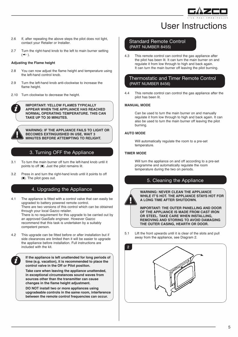
5.2 Remove the glass frame by undoing the fixing screws and lifting clear, see Diagram 3. Take care to support the glass window panel when removing the screws.
NOTE: The Marlborough2 Medium has two additional fixing screws, labelled A.
3
A A
5.3 Place carefully to one side.
5.4 Carefully remove all of the ceramic logs, taking care when handling the front ash panels and set aside. Protect floor coverings and follow the advice give in Section 6.
5.5 The logs should not require cleaning. Do not use a vacuum cleaner or brush to clean the logs, any large pieces of debris may be removed by hand.
5.6 Ensure any debris is removed from the burner ports.
5.7 Replace the ceramics, see Section 7.
5.8 Ensure that the rope seal on the back of the glass frame is intact and replace the screws working from the top down. Tighten the screws evenly DO NOT OVER TIGHTEN, see Diagram 3.
NEVER OPERATE THE APPLIANCE WHEN THE GLASS FRAME IS REMOVED OR BROKEN.
5.9 Replace ALL of the securing screws ensuring that a screw is present in all fixing slots.
UNDER NO CIRCUMSTANCES SHOULD THE APPLIANCE BE USED IF ANY OF THE GLASS FRAME RETAINING SCREWS ARE LOOSE OR MISSING.
5.10 Use a damp cloth to clean the outer casing of the appliance.
6. Arrangement of Fuel Bed
Advice on handling and disposal of fire ceramics
The fuel effect and side panels in this appliance are made from Refractory Ceramic Fibre (RCF), a material which is commonly used for this application.
Protective clothing is not required when handling these articles, but we recommend you follow normal hygiene rules of not smoking, eating or drinking in the work area and always wash your hands before eating or drinking.
To ensure that the release of RCF fibres are kept to a minimum, during installation and servicing a HEPA filtered vacuum is recommended to remove any dust accumulated in and around the appliance before and after working on it. When servicing the appliance it is recommended that the replaced items are not broken up, but are sealed within heavy duty polythene bags and labelled as RCF waste.
RCF waste is classed as stable, non-reactive hazardous waste and may be disposed of at a licensed landfill site.
Excessive exposure to these materials may cause temporary irritation to eyes, skin and respiratory tract; wash hands thoroughly after handling the material.
7. Log Layout
Marlborough2 Small
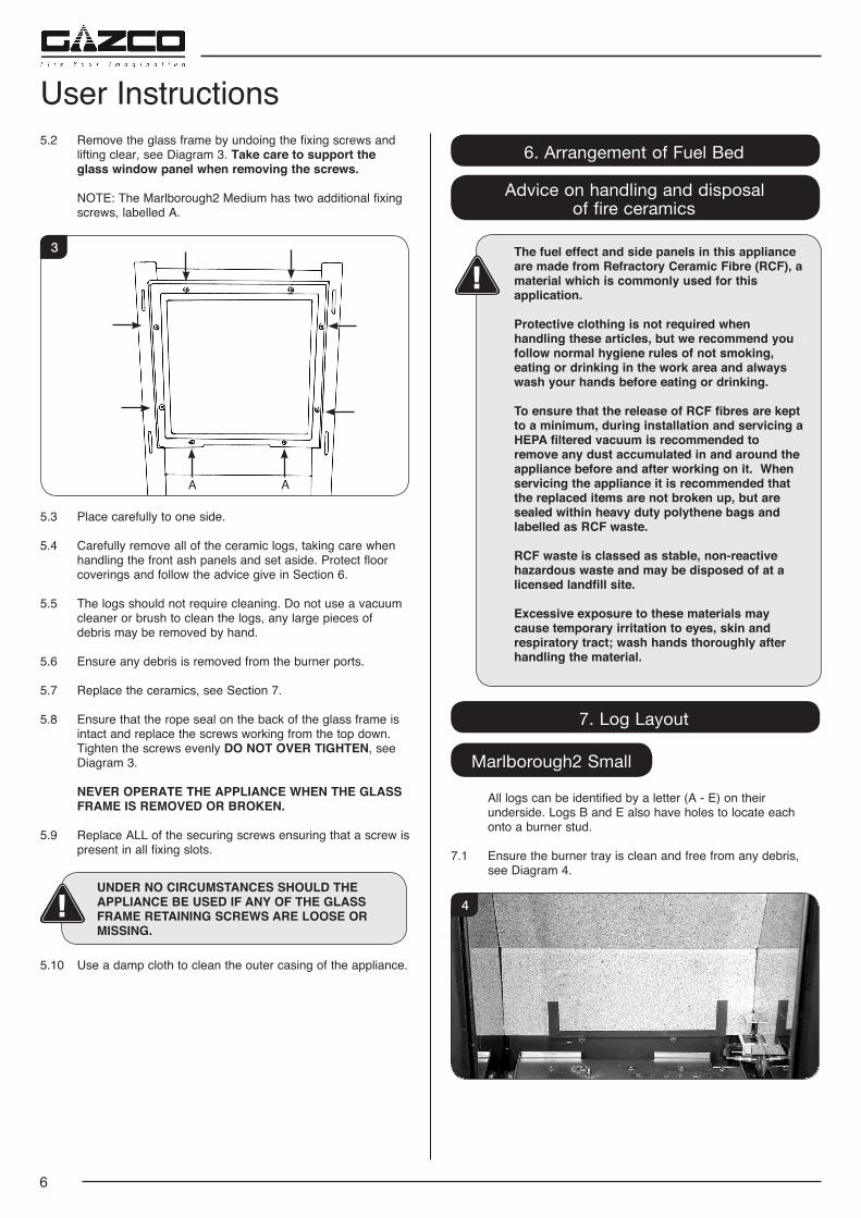
All logs can be identified by a letter (A - E) on their underside. Logs B and E also have holes to locate each onto a burner stud.
7.1 Ensure the burner tray is clean and free from any debris, see Diagram 4.
4
User Instructions
7
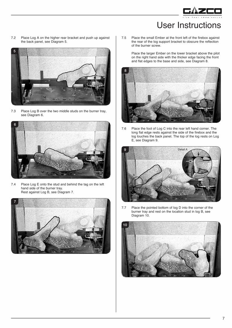
User Instructions7.2 Place Log A on the higher rear bracket and push up against
the back panel, see Diagram 5.
5
7.3 Place Log B over the two middle studs on the burner tray, see Diagram 6.
6
7.4 Place Log E onto the stud and behind the tag on the left hand side of the burner tray.
Rest against Log B, see Diagram 7.
7
7.5 Place the small Ember at the front left of the firebox against the rear of the log support bracket to obscure the reflection of the burner screw.
Place the larger Ember on the lower bracket above the pilot on the right hand side with the thicker edge facing the front and flat edges to the base and side, see Diagram 8.
8
7.6 Place the foot of Log C into the rear left hand corner. The long flat edge rests against the side of the firebox and the log touches the back panel. The top of the log rests on Log E, see Diagram 9.
9 Detail A
A
7.7 Place the pointed bottom of log D into the corner of the burner tray and rest on the location stud in log B, see Diagram 10.
10
8
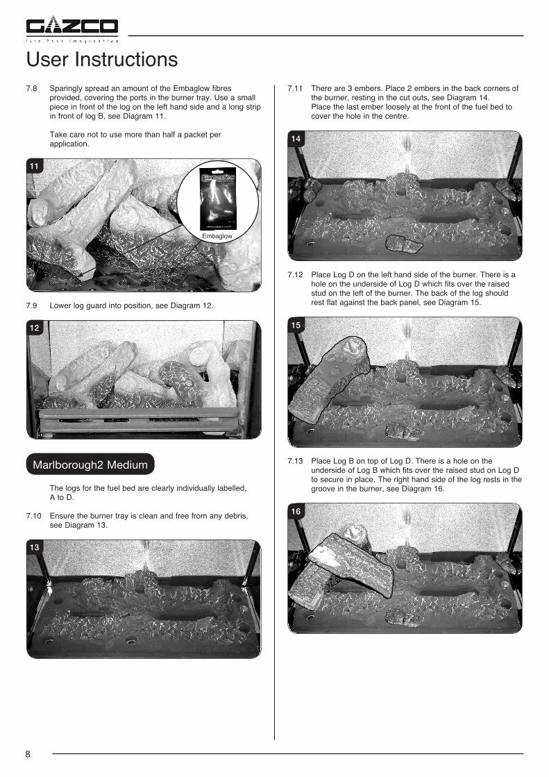
7.8 Sparingly spread an amount of the Embaglow fibres provided, covering the ports in the burner tray. Use a small piece in front of the log on the left hand side and a long strip in front of log B, see Diagram 11.
Take care not to use more than half a packet per application.
Embaglow
11
7.9 Lower log guard into position, see Diagram 12.
12
Marlborough2 Medium
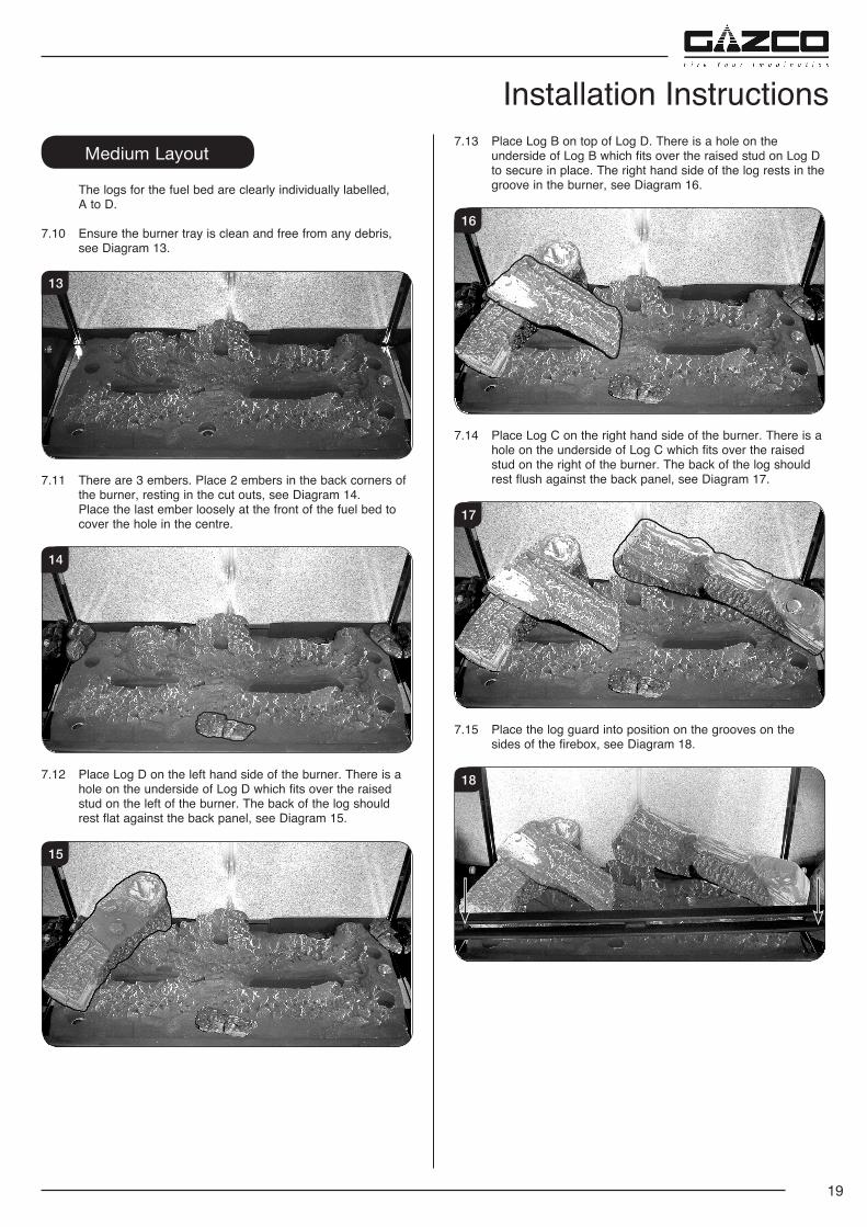
The logs for the fuel bed are clearly individually labelled, A to D.
7.10 Ensure the burner tray is clean and free from any debris, see Diagram 13.
13
7.11 There are 3 embers. Place 2 embers in the back corners of the burner, resting in the cut outs, see Diagram 14.
Place the last ember loosely at the front of the fuel bed to cover the hole in the centre.
14
7.12 Place Log D on the left hand side of the burner. There is a hole on the underside of Log D which fits over the raised stud on the left of the burner. The back of the log should rest flat against the back panel, see Diagram 15.
15
7.13 Place Log B on top of Log D. There is a hole on the underside of Log B which fits over the raised stud on Log D to secure in place. The right hand side of the log rests in the groove in the burner, see Diagram 16.
16
User Instructions
9
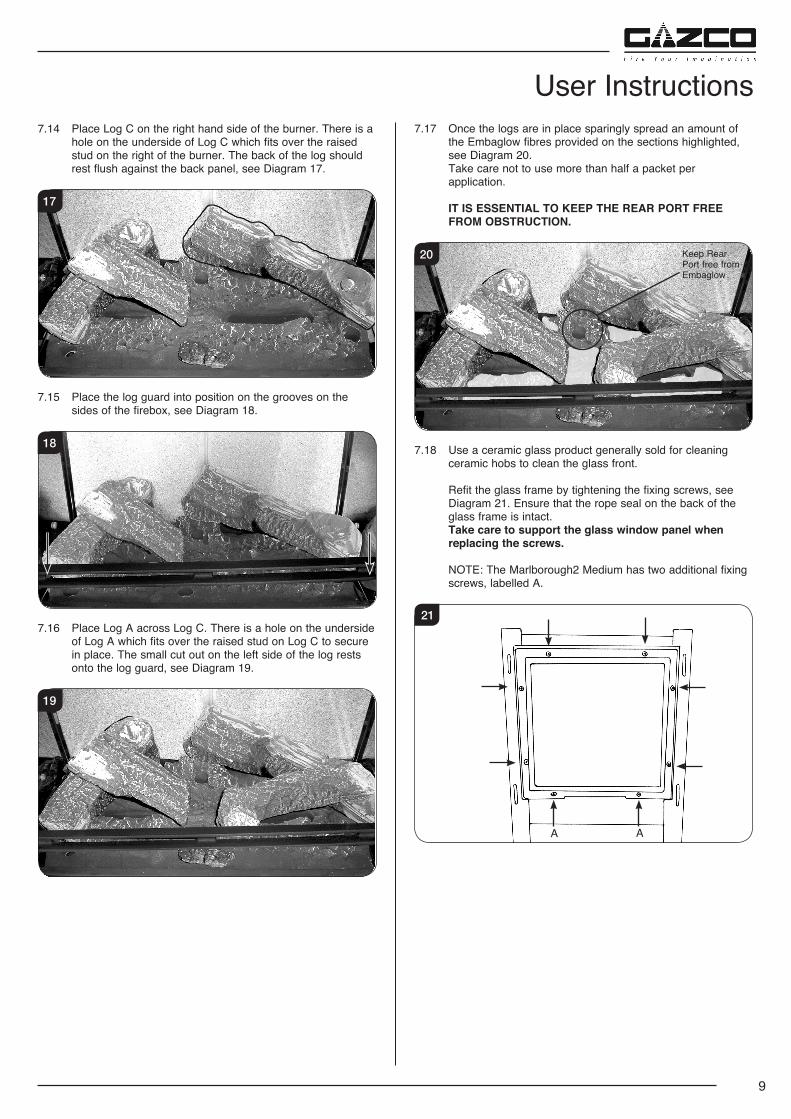
7.14 Place Log C on the right hand side of the burner. There is a hole on the underside of Log C which fits over the raised stud on the right of the burner. The back of the log should rest flush against the back panel, see Diagram 17.
17
7.15 Place the log guard into position on the grooves on the sides of the firebox, see Diagram 18.
18
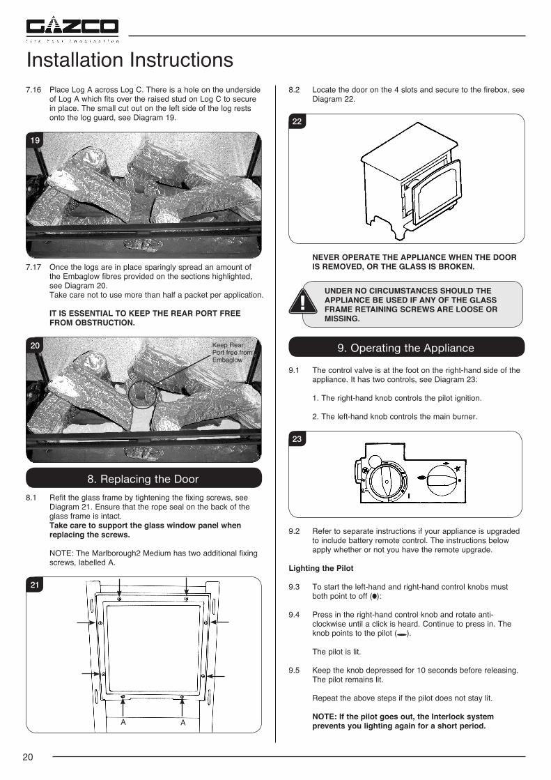
7.16 Place Log A across Log C. There is a hole on the underside of Log A which fits over the raised stud on Log C to secure in place. The small cut out on the left side of the log rests onto the log guard, see Diagram 19.
19
User Instructions7.17 Once the logs are in place sparingly spread an amount of
the Embaglow fibres provided on the sections highlighted, see Diagram 20.
Take care not to use more than half a packet per application.
IT IS ESSENTIAL TO KEEP THE REAR PORT FREE FROM OBSTRUCTION.
20 Keep Rear Port free from Embaglow
7.18 Use a ceramic glass product generally sold for cleaning ceramic hobs to clean the glass front.
Refit the glass frame by tightening the fixing screws, see Diagram 21. Ensure that the rope seal on the back of the glass frame is intact.
Take care to support the glass window panel when replacing the screws.
NOTE: The Marlborough2 Medium has two additional fixing screws, labelled A.
21
A A
10
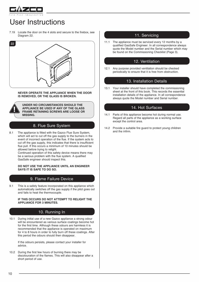
7.19 Locate the door on the 4 slots and secure to the firebox, see Diagram 22.
22
NEVER OPERATE THE APPLIANCE WHEN THE DOOR IS REMOVED, OR THE GLASS IS BROKEN.
UNDER NO CIRCUMSTANCES SHOULD THE APPLIANCE BE USED IF ANY OF THE GLASS FRAME RETAINING SCREWS ARE LOOSE OR MISSING.
8. Flue Sure System8.1 The appliance is fitted with the Gazco Flue Sure System,
which will act to cut off the gas supply to the burners in the event of incorrect operation of the flue. If the system acts to cut off the gas supply, this indicates that there is insufficient flue pull. If this occurs a minimum of 10 minutes should be allowed before trying to relight.
Continued operation of this safety device means there may be a serious problem with the flue system. A qualified GasSafe engineer should inspect this.
DO NOT USE THE APPLIANCE UNTIL AN ENGINEER SAYS IT IS SAFE TO DO SO.
9. Flame Failure Device9.1 This is a safety feature incorporated on this appliance which
automatically switches off the gas supply if the pilot goes out and fails to heat the thermocouple.
IF THIS OCCURS DO NOT ATTEMPT TO RELIGHT THE APPLIANCE FOR 3 MINUTES.
10. Running In10.1 During initial use of a new Gazco appliance a strong odour
will be encountered as various surface coatings become hot for the first time. Although these odours are harmless it is recommended that the appliance is operated on maximum for 4 to 8 hours in order to fully burn off these coatings. After this period the odours should then disappear.
If the odours persists, please contact your installer for advice.
10.2 During the first few hours of burning there may be discolouration of the flames. This will also disappear after a short period of use.
User Instructions11. Servicing
11.1 The appliance must be serviced every 12 months by a qualified GasSafe Engineer. In all correspondence always quote the Model number and the Serial number which may be found on the Commissioning Checklist (Page 3).
12. Ventilation12.1 Any purpose provided ventilation should be checked
periodically to ensure that it is free from obstruction.
13. Installation Details13.1 Your installer should have completed the commissioning
sheet at the front of this book. This records the essential installation details of the appliance. In all correspondence always quote the Model number and Serial number.
14. Hot Surfaces14.1 Parts of this appliance become hot during normal use. Regard all parts of the appliance as a working surface
except the control area.
14.2 Provide a suitable fire guard to protect young children and the infirm.
11
Installation InstructionsTechnical Specification
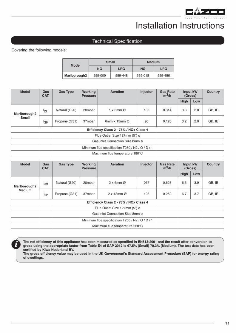
Covering the following models:
Model Gas CAT.
Gas Type WorkingPressure
Aeration Injector Gas Ratem3/h
Input kW (Gross)
Country
High Low
Marlborough2 Small
I2H Natural (G20) 20mbar 1 x 6mm Ø 185 0.314 3.3 2.0 GB, IE
I3P Propane (G31) 37mbar 6mm x 15mm Ø 90 0.120 3.2 2.0 GB, IE
Efficiency Class 2 - 75% / NOx Class 4Flue Outlet Size 127mm (5”) ø
Gas Inlet Connection Size 8mm ø
Minimum flue specification T250 / N2 / O / D / 1Maximum flue temperature 180°C
The net efficiency of this appliance has been measured as specified in EN613:2001 and the result after conversion to gross using the appropriate factor from Table E4 of SAP 2012 is 67.5% (Small) 70.3% (Medium). The test data has been certified by Kiwa Nederland BV. The gross efficiency value may be used in the UK Government's Standard Assessment Procedure (SAP) for energy rating of dwellings.
ModelSmall Medium
NG LPG NG LPG
Marlborough2 559-009 559-448 559-018 559-456
Model Gas CAT.
Gas Type WorkingPressure
Aeration Injector Gas Ratem3/h
Input kW (Gross)
Country
High Low
Marlborough2 Medium
I2H Natural (G20) 20mbar 2 x 6mm Ø 067 0.628 6.6 3.9 GB, IE
I3P Propane (G31) 37mbar 2 x 13mm Ø 128 0.252 6.7 3.7 GB, IE
Efficiency Class 2 - 78% / NOx Class 4Flue Outlet Size 127mm (5”) ø
Gas Inlet Connection Size 8mm ø
Minimum flue specification T250 / N2 / O / D / 1Maximum flue temperature 220°C
12
This appliance has been certified for use in countries other than those stated. To install this appliance in these countries, it is essential to obtain the translated instructions and in some cases the appliance will require modification. Contact Gazco for further information.
Installation InstructionsTechnical Specification
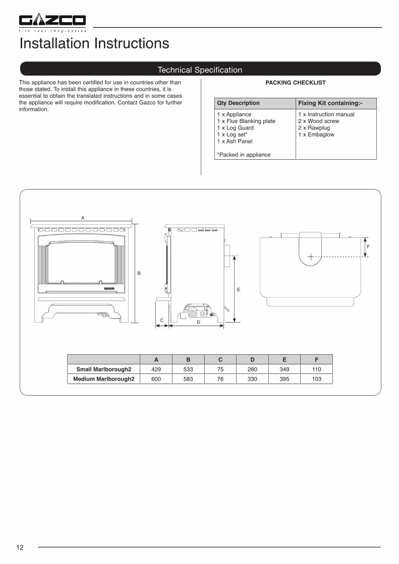
PACKING CHECKLIST
Qty Description Fixing Kit containing:-
1 x Appliance1 x Flue Blanking plate1 x Log Guard1 x Log set*1 x Ash Panel
*Packed in appliance
1 x Instruction manual2 x Wood screw2 x Rawplug1 x Embaglow
A B C D E FSmall Marlborough2 429 533 75 280 349 110
Medium Marlborough2 600 583 76 330 395 103
A
B
C D
E
F
13
1. Flue & Chimney Requirements
1.1 The chimney or flue system must comply with the rules in force, and must be a minimum of 127mm (5") in diameter.
1.2 The minimum flue height for the appliance must be 3 metres (10ft). Any horizontal flue run from the rear outlet must not exceed 100mm from the back of the appliance.
1.3 The chimney or flue must be free from any obstruction. Any damper plates must be removed or secured in the fully open position, and no restrictor plates fitted.
1.4 The chimney must be swept prior to the installation, but it need not be swept if it can be seen the chimney is clean and unobstructed throughout its entire length.
1.5 A 5" (127mm) liner must be used if fitting the appliance into an existing brick built chimney.
Larger lined flues can work, but in some instances could cause cold start flue problems resulting in nuisance shutdown. Lined flues above 7" (175mm) are not recommended.
1.6 The European chimney standards now describe chimneys and flues by their temperature, pressure and resistance to corrosion, condensation and fire. To identify the correct flue system, the minimum flue specification is shown in the Technical Specification. Existing chimneys are not covered by this system.
2. Flue Options
A range of Vitreous Enamel Gloss Black flue pipe is available to compliment the Marlborough2. Please contact your Gazco retailer for further information.
3. Gas Supply
THIS APPLIANCE IS INTENDED FOR USE ON A GAS INSTALLATION WITH A GOVERNED METER.
3.1 Before installation, ensure that the local distribution conditions (identification of the type of gas and pressure) and the adjustment of the appliance are compatible.
3.2 Ensure the gas supply delivers the required amount of gas and is in accordance with the rules in force.
3.3 You can use soft copper tubing on the installation and soft soldered joints outside the appliance and below the fire.
3.4 A means of isolating the gas supply to the appliance must be provided independent of any appliance control.
3.5 All supply gas pipes must be purged of any debris that may have entered prior to connection to the appliance.
3.6 The gas supply must be installed in a way that does not restrict the removal of the appliance for servicing and inspection.
4. Ventilation
IMPORTANT: Ensure any national ventilation requirements are taken into account during installation of the appliance.
FOR THE REPUBLIC OF IRELAND REFER TO THE RULES IN FORCE FOR VENTILATION REQUIREMENTS.
5. Appliance Location
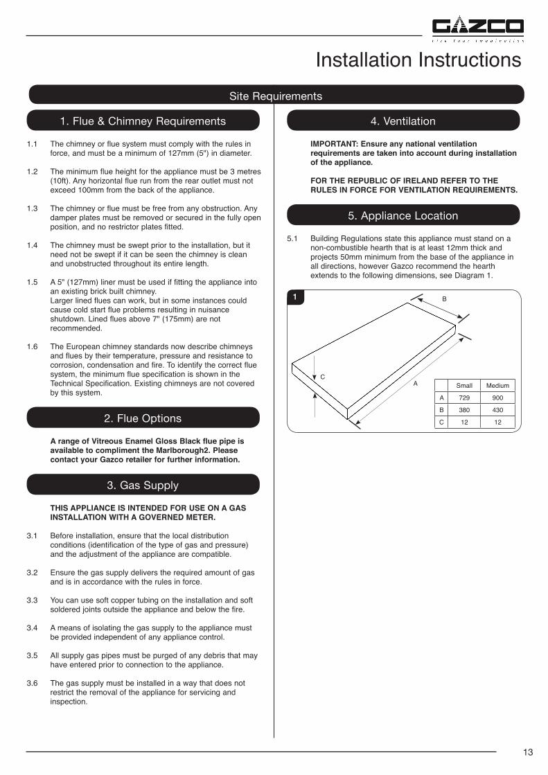
5.1 Building Regulations state this appliance must stand on a non-combustible hearth that is at least 12mm thick and projects 50mm minimum from the base of the appliance in all directions, however Gazco recommend the hearth extends to the following dimensions, see Diagram 1.
Small Medium
A 729 900
B 380 430
C 12 12
CA
B1
Installation InstructionsSite Requirements
14
Installation InstructionsSite Requirements
MINIMUM CLEARANCE
5.2 The appliance is not suitable for installation against a combustible wall.
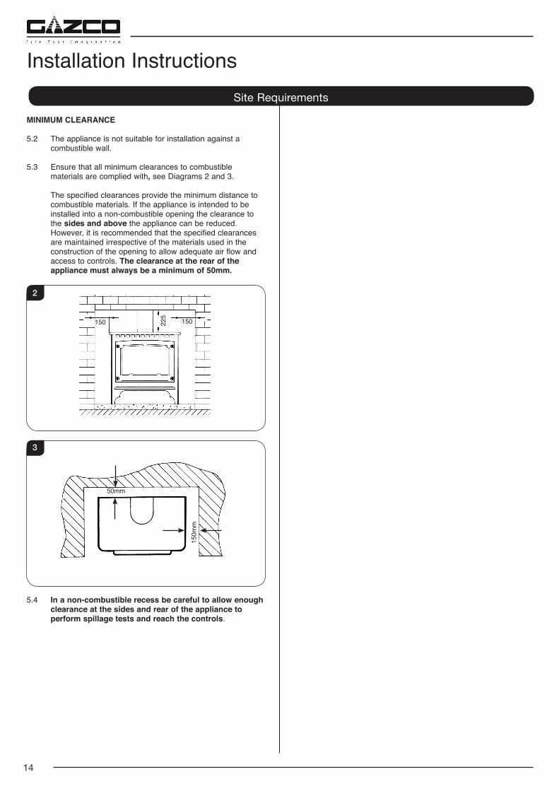
5.3 Ensure that all minimum clearances to combustible materials are complied with, see Diagrams 2 and 3.
The specified clearances provide the minimum distance to combustible materials. If the appliance is intended to be installed into a non-combustible opening the clearance to the sides and above the appliance can be reduced. However, it is recommended that the specified clearances are maintained irrespective of the materials used in the construction of the opening to allow adequate air flow and access to controls. The clearance at the rear of the appliance must always be a minimum of 50mm.
150 225
150
2
50mm
150m
m
3
5.4 In a non-combustible recess be careful to allow enough clearance at the sides and rear of the appliance to perform spillage tests and reach the controls.
15
2. Upgrading the Appliance
2.1 The appliance is fitted with a control valve that can easily be upgraded to battery powered remote control.
There are two versions of this control which can be obtained through your local Gazco retailer.
There is no requirement for this upgrade to be carried out by an approved GasSafe engineer. However Gazco recommend that this task is undertaken by a suitably competent person.
2.2 This upgrade can be fitted before or after installation but if side clearances are limited then it will be easier to upgrade the appliance before installation. Full instructions are included with the kit.
If the appliance is left unattended for long periods of time (e.g. vacation), it is recommended to place the control valve in the Off or Pilot posiiton. Take care when leaving the appliance unattended, in exceptional circumstances sound waves from sources other than the transmitter can cause changes in the flame height adjustment. DO NOT install two or more appliances using upgradeable controls in the same room, interference between the remote control frequencies can occur.
Standard Remote Control (PART NUMBER 8455)
2.3 This remote control can control the gas appliance after the pilot has been lit. It can turn the main burner on and regulate it from low through to high and back again. It can turn the main burner off leaving the pilot burning.
Thermostatic and Timer Remote Control (PART NUMBER 8456)
2.4 This remote control can control the gas appliance after the pilot has been lit.
MANUAL MODE
Can be used to turn the main burner on and manually regulate it from low through to high and back again. It can also be used to turn the main burner off leaving the pilot burning.
AUTO MODE
Will automatically regulate the room to a pre-set temperature.
TIMER MODE
Will turn the appliance on and off according to a pre-set programme and automatically regulate the room temperature during the two on periods.
1. Safety Precautions 1.1 For your own and other’s safety, you must install this
appliance according to local and national codes of practice. Failure to install the appliance correctly could lead to prosecution. Read these instructions before installing and using this appliance.
1.2 These instructions must be left intact with the user.
1.3 Do not attempt to burn rubbish on this appliance.
1.4 Keep all plastic bags away from young children.
1.5 Do not place any object on or near to the appliance and allow adequate clearance above the appliance.
IF THE APPLIANCE IS EXTINGUISHED OR GOES OUT IN USE, WAIT 3 MINUTES BEFORE ATTEMPTING TO RELIGHT THE APPLIANCE.
1.6 The appliance is fitted with the Gazco Flue Sure System, which will act to cut off the gas supply to the burners in the event of incorrect operation of the flue. If the system acts to cut off the gas supply, this indicates that there is insufficient flue pull. If this occurs a minimum of 10 minutes should be allowed before trying to relight. Continued operation of this safety device means there may be a serious problem with the flue system. A qualified GasSafe engineer should inspect this.
1.7 Do not alter or tamper with the Flue Sure System. Use only genuine Gazco replacement parts when servicing the system - refer to the Servicing Section, Replacing Parts.
DO NOT USE THE APPLIANCE UNTIL AN ENGINEER SAYS IT IS SAFE TO DO SO.
IMPORTANT: REFER TO DATA BADGE AND TECHNICAL SPECIFICATION AT THE FRONT OF THE MANUAL TO ENSURE THE APPLIANCE IS CORRECTLY ADJUSTED FOR THE GAS TYPE AND CATEGORY APPLICABLE IN THE COUNTRY OF USE.
FOR DETAILS OF CHANGING BETWEEN GAS TYPES REFER TO SERVICING, SECTION 13, REPLACING PARTS.
Unpacking
1.8 Remove the appliance from its packaging, and check that it is complete and undamaged.
Put the loose ceramic parts to one side so that they are not damaged during installation.
Installation Instructions
16
3. Installation of the Appliance3.1 Decide whether to use top or rear flue exit. The appliance is factory built for rear flue exit but it can be
changed to top exit by swapping the flue spigot and blanking plate located on the appliance.
3.2 Position the appliance ensuring all appropriate clearances are observed.
3.3 Having run the gas supply to the appliance PURGE THE SUPPLY PIPE.
This is essential to expel any debris that can block the gas controls.
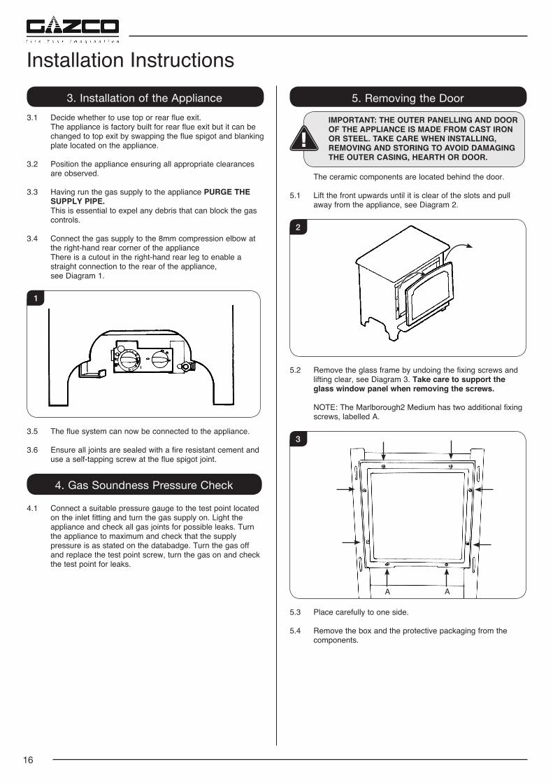
3.4 Connect the gas supply to the 8mm compression elbow at the right-hand rear corner of the appliance
There is a cutout in the right-hand rear leg to enable a straight connection to the rear of the appliance,
see Diagram 1.
1
3.5 The flue system can now be connected to the appliance.
3.6 Ensure all joints are sealed with a fire resistant cement and use a self-tapping screw at the flue spigot joint.
4. Gas Soundness Pressure Check
4.1 Connect a suitable pressure gauge to the test point located on the inlet fitting and turn the gas supply on. Light the appliance and check all gas joints for possible leaks. Turn the appliance to maximum and check that the supply pressure is as stated on the databadge. Turn the gas off and replace the test point screw, turn the gas on and check the test point for leaks.
Installation Instructions5. Removing the Door
IMPORTANT: THE OUTER PANELLING AND DOOR OF THE APPLIANCE IS MADE FROM CAST IRON OR STEEL. TAKE CARE WHEN INSTALLING, REMOVING AND STORING TO AVOID DAMAGING THE OUTER CASING, HEARTH OR DOOR.
The ceramic components are located behind the door.
5.1 Lift the front upwards until it is clear of the slots and pull away from the appliance, see Diagram 2.
2
5.2 Remove the glass frame by undoing the fixing screws and lifting clear, see Diagram 3. Take care to support the glass window panel when removing the screws.
NOTE: The Marlborough2 Medium has two additional fixing screws, labelled A.
3
A A
5.3 Place carefully to one side.
5.4 Remove the box and the protective packaging from the components.
17
Installation Instructions6. Arrangement of Fuel Bed
Advice on handling and disposal of fire ceramics
The fuel effect and side panels in this appliance are made from Refractory Ceramic Fibre (RCF), a material which is commonly used for this application.
Protective clothing is not required when handling these articles, but we recommend you follow normal hygiene rules of not smoking, eating or drinking in the work area and always wash your hands before eating or drinking.
To ensure that the release of RCF fibres are kept to a minimum, during installation and servicing a HEPA filtered vacuum is recommended to remove any dust accumulated in and around the appliance before and after working on it. When servicing the appliance it is recommended that the replaced items are not broken up, but are sealed within heavy duty polythene bags and labelled as RCF waste.
RCF waste is classed as stable, non-reactive hazardous waste and may be disposed of at a licensed landfill site.
Excessive exposure to these materials may cause temporary irritation to eyes, skin and respiratory tract; wash hands thoroughly after handling the material.
7. Log Layout
Small layout
LOGS MUST BE POSITIONED ACCORDING TO THE FOLLOWING INSTRUCTIONS TO GIVE THE CORRECT FLAME EFFECT.
All logs can be identified by a letter (A - E) on their underside. Logs, B and E also have holes to locate each onto a burner stud.
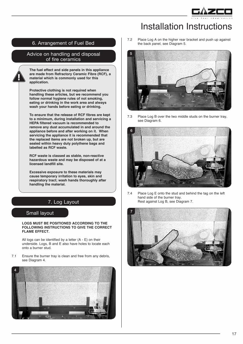
7.1 Ensure the burner tray is clean and free from any debris, see Diagram 4.
4
7.2 Place Log A on the higher rear bracket and push up against the back panel, see Diagram 5.
5
7.3 Place Log B over the two middle studs on the burner tray, see Diagram 6.
6
7.4 Place Log E onto the stud and behind the tag on the left hand side of the burner tray.
Rest against Log B, see Diagram 7.
7
18
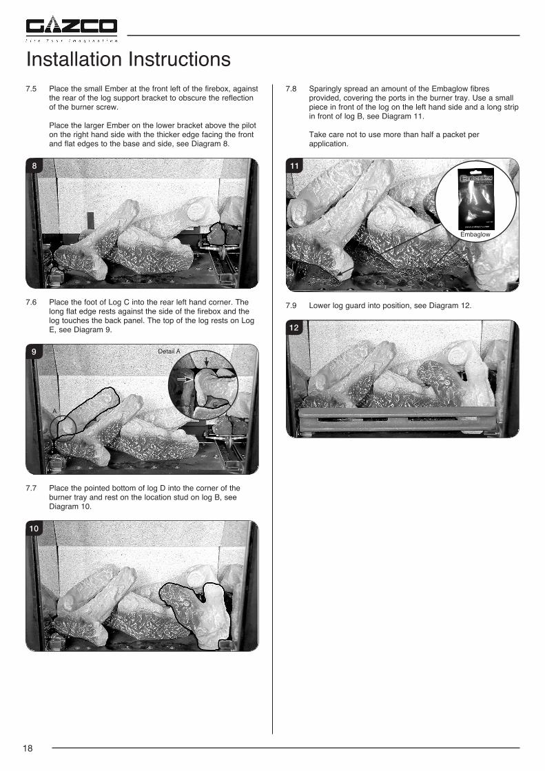
7.5 Place the small Ember at the front left of the firebox, against the rear of the log support bracket to obscure the reflection of the burner screw.
Place the larger Ember on the lower bracket above the pilot on the right hand side with the thicker edge facing the front and flat edges to the base and side, see Diagram 8.
8
7.6 Place the foot of Log C into the rear left hand corner. The long flat edge rests against the side of the firebox and the log touches the back panel. The top of the log rests on Log E, see Diagram 9.
9 Detail A
A
7.7 Place the pointed bottom of log D into the corner of the burner tray and rest on the location stud on log B, see Diagram 10.
10
7.8 Sparingly spread an amount of the Embaglow fibres provided, covering the ports in the burner tray. Use a small piece in front of the log on the left hand side and a long strip in front of log B, see Diagram 11.
Take care not to use more than half a packet per application.
Embaglow
11
7.9 Lower log guard into position, see Diagram 12.
12
Installation Instructions
19
Installation InstructionsMedium Layout
The logs for the fuel bed are clearly individually labelled, A to D.
7.10 Ensure the burner tray is clean and free from any debris, see Diagram 13.
13
7.11 There are 3 embers. Place 2 embers in the back corners of the burner, resting in the cut outs, see Diagram 14.
Place the last ember loosely at the front of the fuel bed to cover the hole in the centre.
14
7.12 Place Log D on the left hand side of the burner. There is a hole on the underside of Log D which fits over the raised stud on the left of the burner. The back of the log should rest flat against the back panel, see Diagram 15.
15
7.13 Place Log B on top of Log D. There is a hole on the underside of Log B which fits over the raised stud on Log D to secure in place. The right hand side of the log rests in the groove in the burner, see Diagram 16.
16
7.14 Place Log C on the right hand side of the burner. There is a hole on the underside of Log C which fits over the raised stud on the right of the burner. The back of the log should rest flush against the back panel, see Diagram 17.
17
7.15 Place the log guard into position on the grooves on the sides of the firebox, see Diagram 18.
18
20
7.16 Place Log A across Log C. There is a hole on the underside of Log A which fits over the raised stud on Log C to secure in place. The small cut out on the left side of the log rests onto the log guard, see Diagram 19.
19
7.17 Once the logs are in place sparingly spread an amount of the Embaglow fibres provided on the sections highlighted, see Diagram 20.
Take care not to use more than half a packet per application.
IT IS ESSENTIAL TO KEEP THE REAR PORT FREE FROM OBSTRUCTION.
20 Keep Rear Port free from Embaglow
8. Replacing the Door8.1 Refit the glass frame by tightening the fixing screws, see
Diagram 21. Ensure that the rope seal on the back of the glass frame is intact.
Take care to support the glass window panel when replacing the screws.
NOTE: The Marlborough2 Medium has two additional fixing screws, labelled A.
21
A A
Installation Instructions8.2 Locate the door on the 4 slots and secure to the firebox, see
Diagram 22.
22
NEVER OPERATE THE APPLIANCE WHEN THE DOOR IS REMOVED, OR THE GLASS IS BROKEN.
UNDER NO CIRCUMSTANCES SHOULD THE APPLIANCE BE USED IF ANY OF THE GLASS FRAME RETAINING SCREWS ARE LOOSE OR MISSING.
9. Operating the Appliance
9.1 The control valve is at the foot on the right-hand side of the appliance. It has two controls, see Diagram 23:
1. The right-hand knob controls the pilot ignition.
2. The left-hand knob controls the main burner.
23
9.2 Refer to separate instructions if your appliance is upgraded to include battery remote control. The instructions below apply whether or not you have the remote upgrade.
Lighting the Pilot
9.3 To start the left-hand and right-hand control knobs must both point to off ( ):
9.4 Press in the right-hand control knob and rotate anti-clockwise until a click is heard. Continue to press in. The knob points to the pilot ( ).
The pilot is lit.
9.5 Keep the knob depressed for 10 seconds before releasing. The pilot remains lit.
Repeat the above steps if the pilot does not stay lit.
NOTE: If the pilot goes out, the Interlock system prevents you lighting again for a short period.
21
1. Commissioning
1.1 Close all doors and windows in the room.
1.2 Ignite the appliance and operate on maximum for 10 minutes.
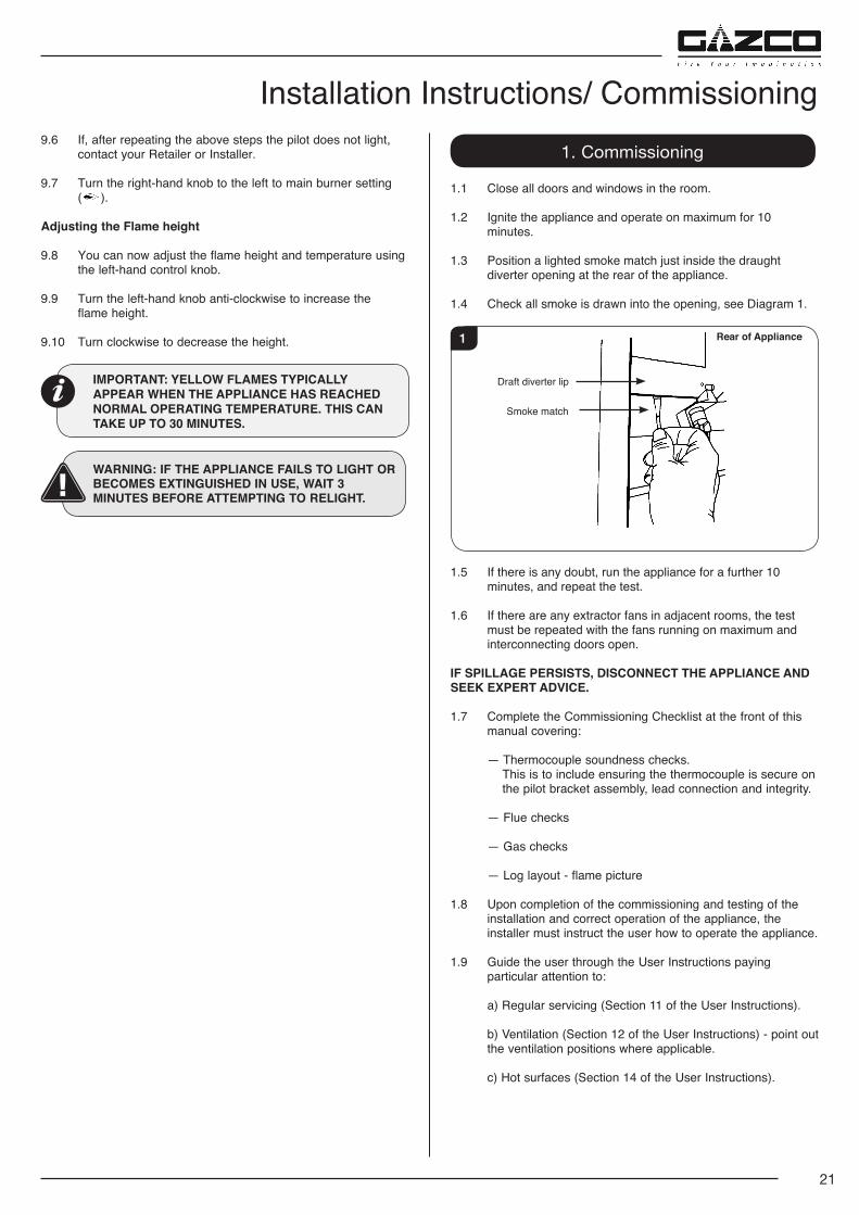
1.3 Position a lighted smoke match just inside the draught diverter opening at the rear of the appliance.
1.4 Check all smoke is drawn into the opening, see Diagram 1.
1 Rear of Appliance
Draft diverter lip
Smoke match
1.5 If there is any doubt, run the appliance for a further 10 minutes, and repeat the test.
1.6 If there are any extractor fans in adjacent rooms, the test must be repeated with the fans running on maximum and interconnecting doors open.
IF SPILLAGE PERSISTS, DISCONNECT THE APPLIANCE AND SEEK EXPERT ADVICE.
1.7 Complete the Commissioning Checklist at the front of this manual covering:
— Thermocouple soundness checks. This is to include ensuring the thermocouple is secure on the pilot bracket assembly, lead connection and integrity.
— Flue checks
— Gas checks
— Log layout - flame picture
1.8 Upon completion of the commissioning and testing of the installation and correct operation of the appliance, the installer must instruct the user how to operate the appliance.
1.9 Guide the user through the User Instructions paying particular attention to:
a) Regular servicing (Section 11 of the User Instructions).
b) Ventilation (Section 12 of the User Instructions) - point out the ventilation positions where applicable.
c) Hot surfaces (Section 14 of the User Instructions).
Installation Instructions/ Commissioning9.6 If, after repeating the above steps the pilot does not light,
contact your Retailer or Installer.
9.7 Turn the right-hand knob to the left to main burner setting ( ).
Adjusting the Flame height
9.8 You can now adjust the flame height and temperature using the left-hand control knob.
9.9 Turn the left-hand knob anti-clockwise to increase the flame height.
9.10 Turn clockwise to decrease the height.
IMPORTANT: YELLOW FLAMES TYPICALLY APPEAR WHEN THE APPLIANCE HAS REACHED NORMAL OPERATING TEMPERATURE. THIS CAN TAKE UP TO 30 MINUTES.
WARNING: IF THE APPLIANCE FAILS TO LIGHT OR BECOMES EXTINGUISHED IN USE, WAIT 3 MINUTES BEFORE ATTEMPTING TO RELIGHT.
22
1. Servicing Requirements
IMPORTANT – The glass panel on this appliance should be checked for any signs of damage on the front face of the glass panel (scratches, scores, cracks or other surface defects). If damage is observed, the glass panel must be replaced and the appliance must not be used until a replacement is installed. Under no circumstances should the appliance be used if any damage is observed. Please isolate the appliance until a replacement glass panel has been obtained and installed. Replacement glass panels can be purchased from Gazco via the retailer from which the appliance was purchased or any other Gazco distributor.
This appliance must be serviced at least once a year by a competent person.
All tests must be carried out in accordance with the current GasSafe recommendations.
1.1 Before Testing:
— Conduct a gas soundness test for the property ensuring there are no leaks before servicing.
— Check the operation of the appliance before testing.
1.2 Special checks:
— Clean the burner using a vacuum cleaner with a soft brush attachment. Ensure all debris is removed from the burner ports.
— Clean any lint or fluff from the pilot - pay particular attention to the aeration holes of the pilot
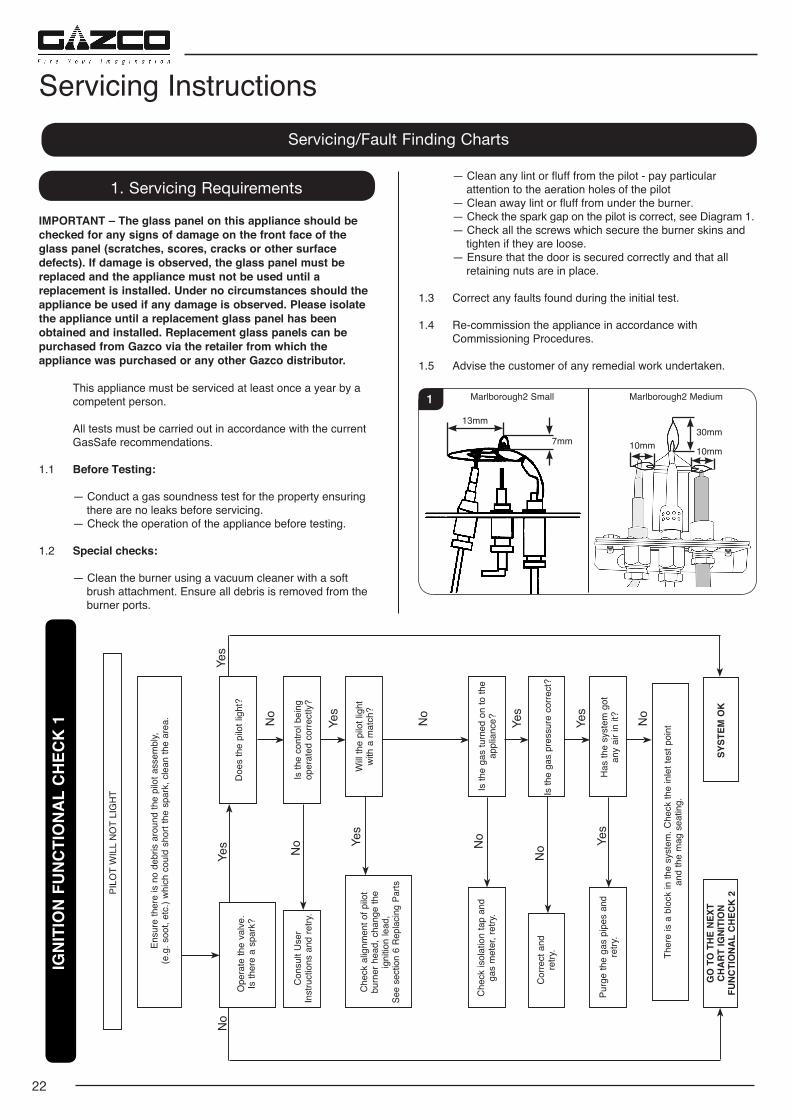
— Clean away lint or fluff from under the burner. — Check the spark gap on the pilot is correct, see Diagram 1. — Check all the screws which secure the burner skins and
tighten if they are loose. — Ensure that the door is secured correctly and that all
retaining nuts are in place.
1.3 Correct any faults found during the initial test.
1.4 Re-commission the appliance in accordance with Commissioning Procedures.
1.5 Advise the customer of any remedial work undertaken.
13mm
Marlborough2 Small Marlborough2 Medium
7mm
1
30mm
10mm10mm
Servicing InstructionsServicing/Fault Finding Charts
IGN
ITIO
N F
UN
CTI
ON
AL
CH
ECK
1
PILO
T W
ILL
NO
T LI
GH
T
Ensu
re th
ere
is n
o de
bris
aro
und
the
pilo
t ass
embl
y,
(e.g
. soo
t, et
c.) w
hich
cou
ld s
hort
the
spar
k, c
lean
the
area
.
Ope
rate
the
valv
e.Is
ther
e a
spar
k?
Con
sult
Use
r In
stru
ctio
ns a
nd re
try.
Che
ck a
lignm
ent o
f pilo
t bu
rner
hea
d, c
hang
e th
e ig
nitio
n le
ad,
See
sect
ion
6 Re
plac
ing
Parts
Che
ck is
olat
ion
tap
and
gas
met
er, r
etry
.
Cor
rect
and
re
try.
Purg
e th
e ga
s pi
pes
and
retry
.
GO
TO
TH
E N
EXT
C
HA
RT
IGN
ITIO
N
FUN
CTI
ON
AL
CH
ECK
2SY
STEM
OK
Ther
e is
a b
lock
in th
e sy
stem
. Che
ck th
e in
let t
est p
oint
an
d th
e m
ag s
eatin
g.
Is th
e ga
s tu
rned
on
to th
e ap
plia
nce?
Is th
e ga
s pr
essu
re c
orre
ct?
Has
the
syst
em g
ot
any
air i
n it?
Doe
s th
e pi
lot l
ight
?
Is th
e co
ntro
l bei
ng
oper
ated
cor
rect
ly?
Will
the
pilo
t lig
ht
with
a m
atch
?
No
Yes
No
Yes
No
Yes
Yes
No
NoYe
s
No
No Ye
s
Yes
23
IGN
ITIO
N F
UN
CTI
ON
AL
CH
ECK
2
Rem
ove
the
igni
tion
lead
from
th
e pi
ezo.
Ope
rate
the
valv
e.
Doe
s a
spar
k ju
mp
from
the
piez
o to
the
valv
e bo
dy?
Yes
NO
SPA
RK
Ensu
re th
ere
is n
o de
bris
aro
und
the
pilo
t ass
embl
y, (e
.g. s
oot e
tc.)
whi
ch c
ould
sho
rt th
e sp
ark,
cle
an th
e ar
ea.
Con
sult
the
user
s in
stru
ctio
ns, r
etry
.
Ope
rate
the
valv
e to
ligh
t th
e pi
lot,
does
the
valv
e 'cl
ick'?
Is th
e pI
lot b
urne
r ho
rizon
tal?
See
Serv
icin
g R
equi
rem
ents
Dia
gram
1.
Has
igni
tion
lead
be
com
e de
tach
ed o
r is
conn
ectio
n po
or?
Rem
ove
the
igni
tion
lead
fro
m e
lect
rode
with
insu
late
d
plie
rs. H
old
the
tip 4
mm
from
the
pi
lot p
ipew
ork,
is th
ere
a sp
ark
w
hen
the
valv
e ‘c
licks
’?
Is th
e ig
ntio
n le
ad d
etac
hed
from
the
piez
o
in th
e va
lve?
Rep
lace
the
com
bine
d le
ad a
nd p
iezo
, ret
ry.
Cor
rect
and
retry
.
Che
ck fo
r def
ectiv
e or
da
mag
ed c
ontro
l kno
b sp
indl
e
or c
am o
pera
tion.
Che
ck fo
r co
rrect
loca
tion
of p
iezo
co
mpo
nent
s. C
orre
ct a
nd re
try.
Is th
e co
ntro
l sys
tem
bei
ng
oper
ated
cor
rect
ly?
Res
et th
e el
ectro
de g
ap,
retry
.
Yes
Yes
Yes
No
No
No
Yes
Yes
Yes
No N
o
Rep
lace
the
pilo
t uni
t.R
epla
ce th
e ig
nitio
n
lead
and
retry
.
FLA
ME
FAIL
UR
E FU
NC
TIO
NA
L C
HEC
K 3
PILO
T W
ILL
NO
T ST
AY L
IT O
R F
IRE
GO
ES O
UT
IN U
SE
Ensu
re th
ere
is n
o de
bris
aro
und
the
pilo
t ass
embl
y, e.
g. c
oal,
soot
etc
. whi
ch c
ould
sho
rt th
e sp
ark,
cle
an th
e ar
ea.
Prob
lem
is w
ith th
e pi
pe w
ork
or
fittin
gs w
hich
lead
to
the
appl
ianc
e.
Cor
rect
an
d re
try.
Is th
erm
ocou
ple
conn
ectio
n go
od
in b
ack
of v
alve
?
Rep
lace
th
erm
ocou
ple.
Will
pilo
t st
ay a
light
?
Cha
nge
mag
un
it.
Is th
e pi
lot f
lam
e of
th
e co
rrect
leng
th?
Se
e Se
rvic
ing
Req
uire
men
ts
Dia
gram
1.
Cha
nge
the
pilo
t uni
t.
Will
pilo
t st
ay a
light
?W
ith th
e pi
lot
runn
ing
is th
e ga
s pr
essu
re a
s st
ated
on
the
data
bad
ge?
With
the
appl
ianc
e ru
nnin
g on
full
is th
e ga
s at
th
e pr
essu
re s
tate
d
on th
e da
ta b
adge
?
Run
for n
o m
ore
than
60
seco
nds
tu
rn o
ff, ti
me
inte
rval
un
til m
ag u
nit s
huts
w
ith a
clic
k. Is
this
gr
eate
r tha
n 7
seco
nds?
Run
for a
max
imum
of
60 s
econ
ds, t
urn
off,
time
inte
rval
unt
il m
ag
unit
shut
s w
ith a
clic
k.
Is th
is g
reat
er th
an 7
se
cond
s?
Tigh
ten
the
co
nnec
tion
and
retry
.
No
No
No
No
No
No
Yes
SYST
EM O
K
Yes
Yes
Yes
Yes
No
Yes
Yes
NoLigh
t the
pilo
t and
kee
p th
e co
ntro
l kno
b pu
shed
in
at le
ast 1
0 se
cond
s be
fore
rele
asin
g.
Is th
e flu
e w
orki
ng?
Rec
tify
flue
No
Yes
Yes
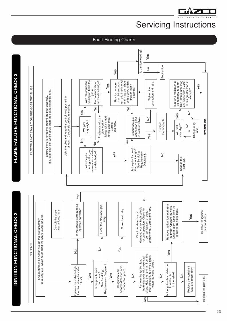
Fault Finding Charts
Servicing Instructions
24
2.3 Place carefully to one side.
2.4 Lift out the log guard and carefully remove the ceramic fuel bed components.
2.5 Refit in reverse order ensuring that the rope seal is intact.
2.6 Locate the door on the 4 slots and secure to the firebox.
NEVER OPERATE THE APPLIANCE WHEN THE DOOR IS REMOVED, OR THE GLASS IS BROKEN.
UNDER NO CIRCUMSTANCES SHOULD THE APPLIANCE BE USED IF ANY OF THE GLASS FRAME RETAINING SCREWS ARE LOOSE OR MISSING.
3. Baffle & Ceramic Liners
3.1 To access the burner tray and interior workings of the appliance it may be necessary to remove the baffle and the liners.
3a. Liners (Marlborough2 small only)
BAFFLE
3.2 There is no requirement to remove the baffle for servicing.
LINERS
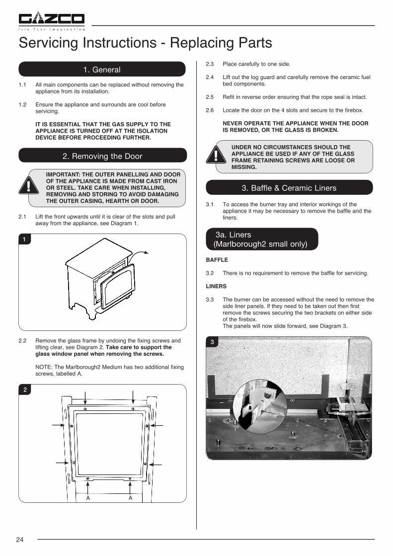
3.3 The burner can be accessed without the need to remove the side liner panels. If they need to be taken out then first remove the screws securing the two brackets on either side of the firebox.
The panels will now slide forward, see Diagram 3.
3
1. General
1.1 All main components can be replaced without removing the appliance from its installation.
1.2 Ensure the appliance and surrounds are cool before servicing.
IT IS ESSENTIAL THAT THE GAS SUPPLY TO THE APPLIANCE IS TURNED OFF AT THE ISOLATION DEVICE BEFORE PROCEEDING FURTHER.
2. Removing the Door
IMPORTANT: THE OUTER PANELLING AND DOOR OF THE APPLIANCE IS MADE FROM CAST IRON OR STEEL. TAKE CARE WHEN INSTALLING, REMOVING AND STORING TO AVOID DAMAGING THE OUTER CASING, HEARTH OR DOOR.
2.1 Lift the front upwards until it is clear of the slots and pull away from the appliance, see Diagram 1.
1
2.2 Remove the glass frame by undoing the fixing screws and lifting clear, see Diagram 2. Take care to support the glass window panel when removing the screws.
NOTE: The Marlborough2 Medium has two additional fixing screws, labelled A.
2
A A
Servicing Instructions - Replacing Parts
25
Servicing Instructions - Replacing Parts3.4 Gently lift the upper rear liner and pull forwards. With the panel raised it should be possible to remove from
the liner brackets, see Diagram 4. Note: It may be necessary to use a flat object like a
screwdriver to separate the two panels.
4
3.5 Slide the lower rear liner up and out of the lower bracket, see Diagram 5.
5
3.6 Replace all parts in reverse order ensuring the cutouts in the rear of the lower panel fit over the screws on the back of the firebox, see Diagram 6.
6
3b. Baffle & Liners (Marlborough2 Medium only)
3.7 To access the burner tray and interior workings of the appliance it may be necessary to remove the baffles and the liners.
3.8 This appliance has 2 baffles, 1 metal and 1 vermiculite, that must be removed before the liners can be taken out of the appliance.
3.9 Remove the logs.
METAL BAFFLE
To remove the metal baffle:
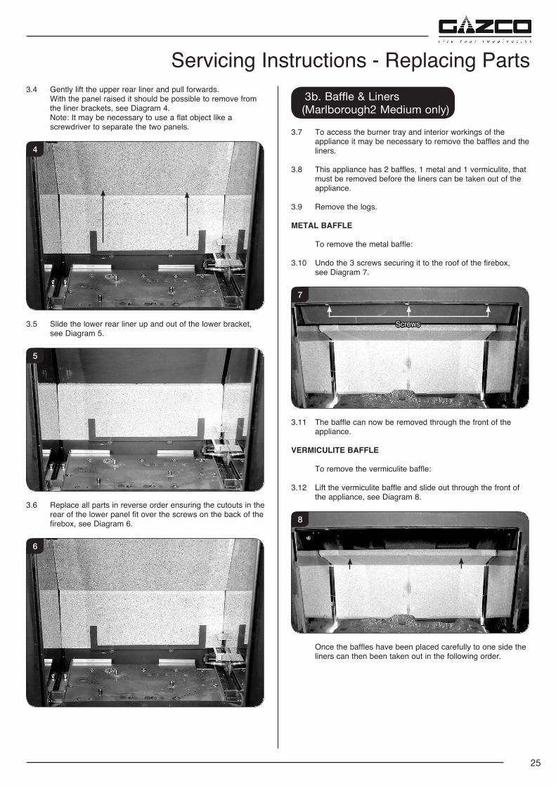
3.10 Undo the 3 screws securing it to the roof of the firebox, see Diagram 7.
Screws
7
3.11 The baffle can now be removed through the front of the appliance.
VERMICULITE BAFFLE
To remove the vermiculite baffle:
3.12 Lift the vermiculite baffle and slide out through the front of the appliance, see Diagram 8.
8
Once the baffles have been placed carefully to one side the liners can then been taken out in the following order.
26
REFLECTIVE LINERS
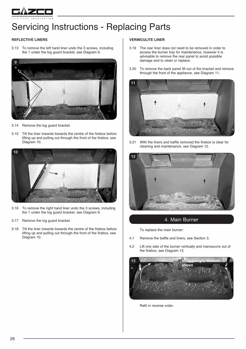
3.13 To remove the left hand liner undo the 3 screws, including the 1 under the log guard bracket, see Diagram 9.
9
3.14 Remove the log guard bracket.
3.15 Tilt the liner inwards towards the centre of the firebox before lifting up and pulling out through the front of the firebox, see Diagram 10.
10
3.16 To remove the right hand liner undo the 3 screws, including the 1 under the log guard bracket, see Diagram 9.
3.17 Remove the log guard bracket.
3.18 Tilt the liner inwards towards the centre of the firebox before lifting up and pulling out through the front of the firebox, see Diagram 10.
VERMICULITE LINER
3.19 The rear liner does not need to be removed in order to access the burner tray for maintenance, however it is advisable to remove the rear panel to avoid possible damage and to clean or replace.
3.20 To remove the back panel lift out of the bracket and remove through the front of the appliance, see Diagram 11.
11
3.21 With the liners and baffle removed the firebox is clear for cleaning and maintenance, see Diagram 12.
12
4. Main Burner
To replace the main burner:
4.1 Remove the baffle and liners, see Section 3.
4.2 Lift one side of the burner vertically and manoeuvre out of the firebox, see Diagram 13.
13 Marlborough2 Medium shown
Refit in reverse order.
Servicing Instructions - Replacing Parts
27
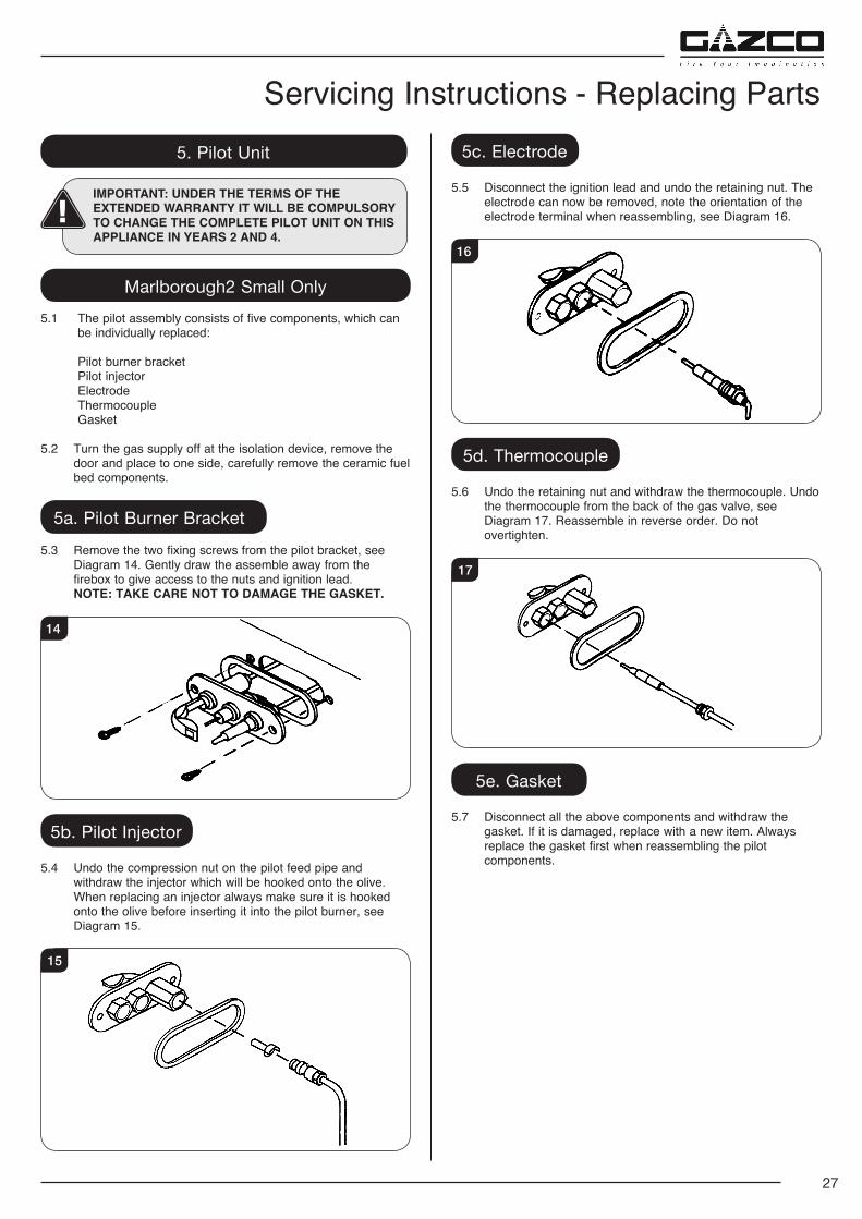
Servicing Instructions - Replacing Parts5. Pilot Unit
IMPORTANT: UNDER THE TERMS OF THE EXTENDED WARRANTY IT WILL BE COMPULSORY TO CHANGE THE COMPLETE PILOT UNIT ON THIS APPLIANCE IN YEARS 2 AND 4.
Marlborough2 Small Only5.1 The pilot assembly consists of five components, which can
be individually replaced:
Pilot burner bracket Pilot injector Electrode Thermocouple Gasket
5.2 Turn the gas supply off at the isolation device, remove the door and place to one side, carefully remove the ceramic fuel bed components.
5a. Pilot Burner Bracket5.3 Remove the two fixing screws from the pilot bracket, see
Diagram 14. Gently draw the assemble away from the firebox to give access to the nuts and ignition lead.
NOTE: TAKE CARE NOT TO DAMAGE THE GASKET.
14
5b. Pilot Injector
5.4 Undo the compression nut on the pilot feed pipe and withdraw the injector which will be hooked onto the olive. When replacing an injector always make sure it is hooked onto the olive before inserting it into the pilot burner, see Diagram 15.
15
5c. Electrode
5.5 Disconnect the ignition lead and undo the retaining nut. The electrode can now be removed, note the orientation of the electrode terminal when reassembling, see Diagram 16.
16
5d. Thermocouple
5.6 Undo the retaining nut and withdraw the thermocouple. Undo the thermocouple from the back of the gas valve, see Diagram 17. Reassemble in reverse order. Do not overtighten.
17
5e. Gasket
5.7 Disconnect all the above components and withdraw the gasket. If it is damaged, replace with a new item. Always replace the gasket first when reassembling the pilot components.
28
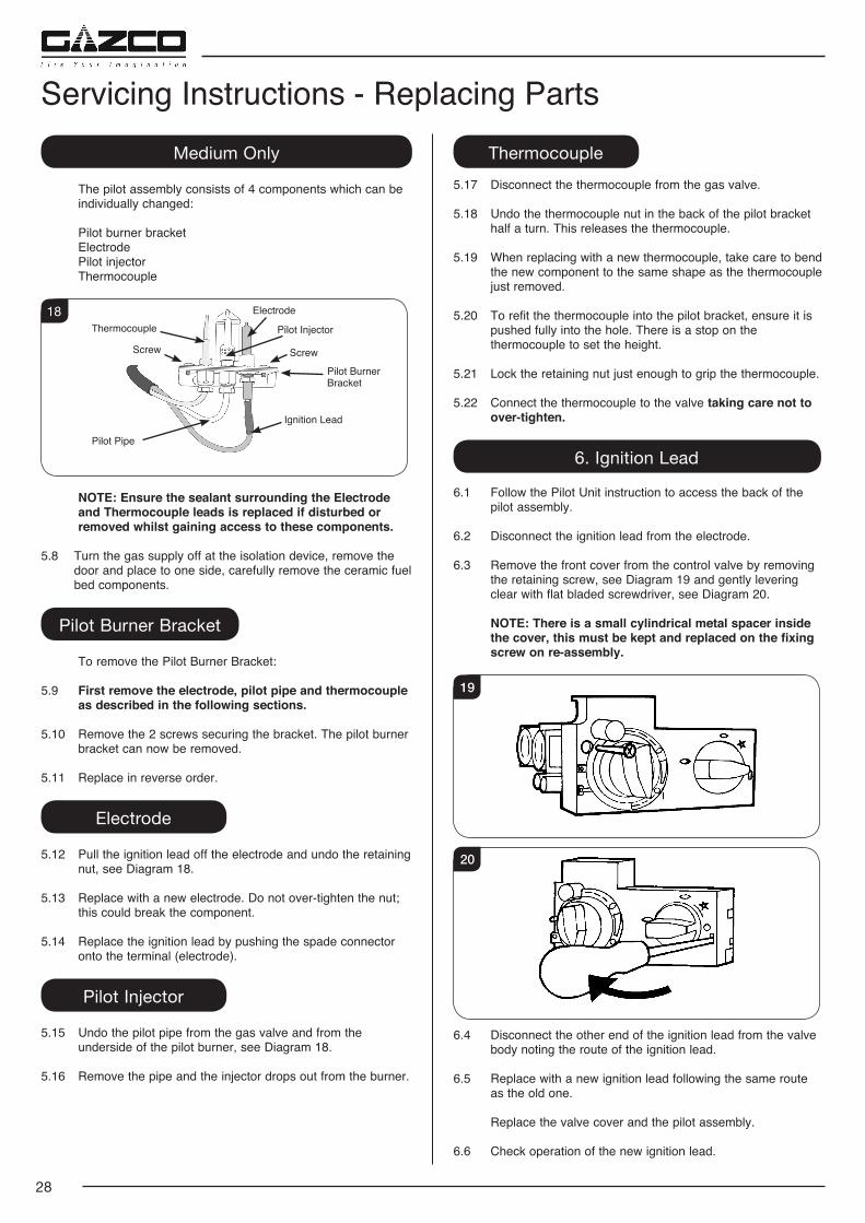
Servicing Instructions - Replacing PartsMedium Only
The pilot assembly consists of 4 components which can be individually changed:
Pilot burner bracket Electrode Pilot injector Thermocouple
18 ElectrodeThermocouple Pilot Injector
Pilot Burner Bracket
Ignition Lead
Pilot Pipe
Screw Screw
NOTE: Ensure the sealant surrounding the Electrode and Thermocouple leads is replaced if disturbed or removed whilst gaining access to these components.
5.8 Turn the gas supply off at the isolation device, remove the door and place to one side, carefully remove the ceramic fuel bed components.
Pilot Burner Bracket
To remove the Pilot Burner Bracket:
5.9 First remove the electrode, pilot pipe and thermocouple as described in the following sections.
5.10 Remove the 2 screws securing the bracket. The pilot burner bracket can now be removed.
5.11 Replace in reverse order.
Electrode
5.12 Pull the ignition lead off the electrode and undo the retaining nut, see Diagram 18.
5.13 Replace with a new electrode. Do not over-tighten the nut; this could break the component.
5.14 Replace the ignition lead by pushing the spade connector onto the terminal (electrode).
Pilot Injector
5.15 Undo the pilot pipe from the gas valve and from the underside of the pilot burner, see Diagram 18.
5.16 Remove the pipe and the injector drops out from the burner.
Thermocouple5.17 Disconnect the thermocouple from the gas valve. 5.18 Undo the thermocouple nut in the back of the pilot bracket
half a turn. This releases the thermocouple. 5.19 When replacing with a new thermocouple, take care to bend
the new component to the same shape as the thermocouple just removed.
5.20 To refit the thermocouple into the pilot bracket, ensure it is pushed fully into the hole. There is a stop on the thermocouple to set the height.
5.21 Lock the retaining nut just enough to grip the thermocouple.
5.22 Connect the thermocouple to the valve taking care not to over-tighten.
6. Ignition Lead
6.1 Follow the Pilot Unit instruction to access the back of the pilot assembly.
6.2 Disconnect the ignition lead from the electrode.
6.3 Remove the front cover from the control valve by removing the retaining screw, see Diagram 19 and gently levering clear with flat bladed screwdriver, see Diagram 20.
NOTE: There is a small cylindrical metal spacer inside the cover, this must be kept and replaced on the fixing screw on re-assembly.
19
20
6.4 Disconnect the other end of the ignition lead from the valve body noting the route of the ignition lead.
6.5 Replace with a new ignition lead following the same route as the old one.
Replace the valve cover and the pilot assembly.
6.6 Check operation of the new ignition lead.
29
Servicing Instructions - Replacing Parts7. Piezo
7.1 The piezo assembly used on this appliance is not serviceable and is unlikely to fail.
7.2 If a new piezo is required it will be necessary to change the valve, see Section 8.
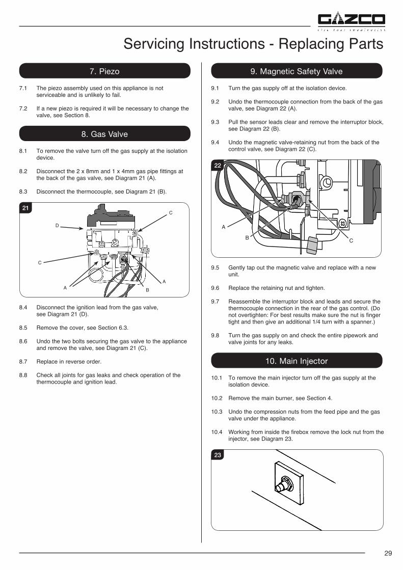
8. Gas Valve
8.1 To remove the valve turn off the gas supply at the isolation device.
8.2 Disconnect the 2 x 8mm and 1 x 4mm gas pipe fittings at the back of the gas valve, see Diagram 21 (A).
8.3 Disconnect the thermocouple, see Diagram 21 (B).
C
C
B
A
D
A
21
8.4 Disconnect the ignition lead from the gas valve, see Diagram 21 (D).
8.5 Remove the cover, see Section 6.3.
8.6 Undo the two bolts securing the gas valve to the appliance and remove the valve, see Diagram 21 (C).
8.7 Replace in reverse order.
8.8 Check all joints for gas leaks and check operation of the thermocouple and ignition lead.
9. Magnetic Safety Valve
9.1 Turn the gas supply off at the isolation device.
9.2 Undo the thermocouple connection from the back of the gas valve, see Diagram 22 (A).
9.3 Pull the sensor leads clear and remove the interruptor block, see Diagram 22 (B).
9.4 Undo the magnetic valve-retaining nut from the back of the control valve, see Diagram 22 (C).
CB
A
22
9.5 Gently tap out the magnetic valve and replace with a new unit.
9.6 Replace the retaining nut and tighten.
9.7 Reassemble the interruptor block and leads and secure the thermocouple connection in the rear of the gas control. (Do not overtighten: For best results make sure the nut is finger tight and then give an additional 1/4 turn with a spanner.)
9.8 Turn the gas supply on and check the entire pipework and valve joints for any leaks.
10. Main Injector
10.1 To remove the main injector turn off the gas supply at the isolation device.
10.2 Remove the main burner, see Section 4.
10.3 Undo the compression nuts from the feed pipe and the gas valve under the appliance.
10.4 Working from inside the firebox remove the lock nut from the injector, see Diagram 23.
23
30
10.5 Extract the injector with the feed pipe from beneath the appliance.
10.6 Holding the injector with a spanner:
10.7 Undo the feed pipe. Note the orientation of the Injector.
10.8 Re-assemble in reverse order.
10.9 Turn on the gas supply and check for leaks.
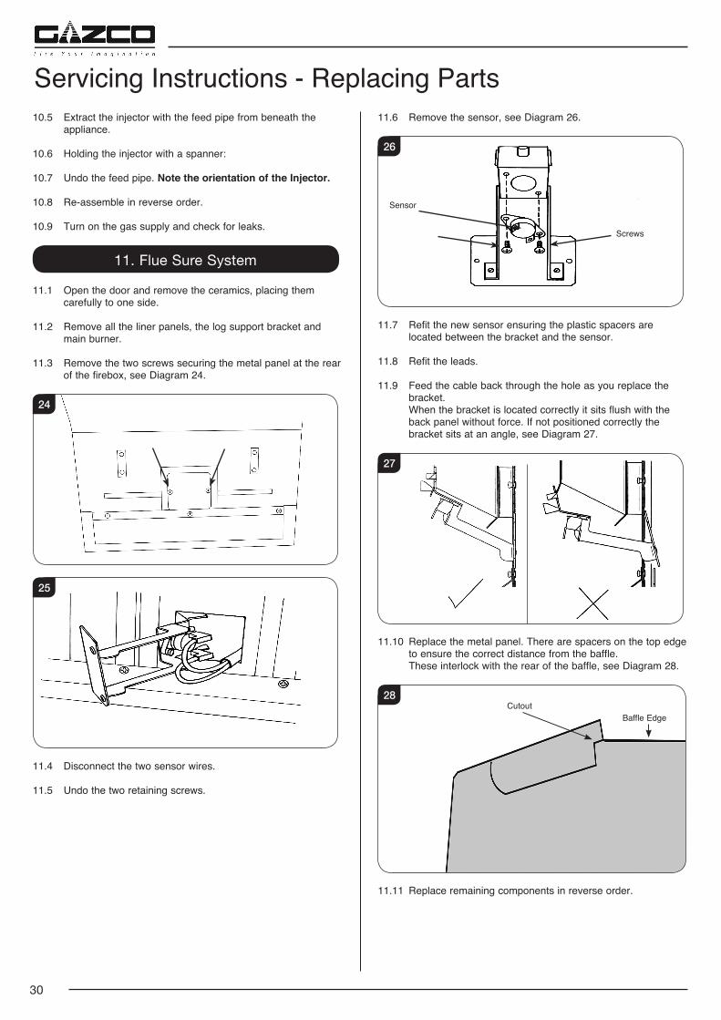
11. Flue Sure System
11.1 Open the door and remove the ceramics, placing them carefully to one side.
11.2 Remove all the liner panels, the log support bracket and main burner.
11.3 Remove the two screws securing the metal panel at the rear of the firebox, see Diagram 24.
24
25
11.4 Disconnect the two sensor wires.
11.5 Undo the two retaining screws.
Servicing Instructions - Replacing Parts11.6 Remove the sensor, see Diagram 26.
26
Screws
Sensor
11.7 Refit the new sensor ensuring the plastic spacers are located between the bracket and the sensor.
11.8 Refit the leads.
11.9 Feed the cable back through the hole as you replace the bracket.
When the bracket is located correctly it sits flush with the back panel without force. If not positioned correctly the bracket sits at an angle, see Diagram 27.
27
11.10 Replace the metal panel. There are spacers on the top edge to ensure the correct distance from the baffle.
These interlock with the rear of the baffle, see Diagram 28.
28
Baffle EdgeCutout
11.11 Replace remaining components in reverse order.
31
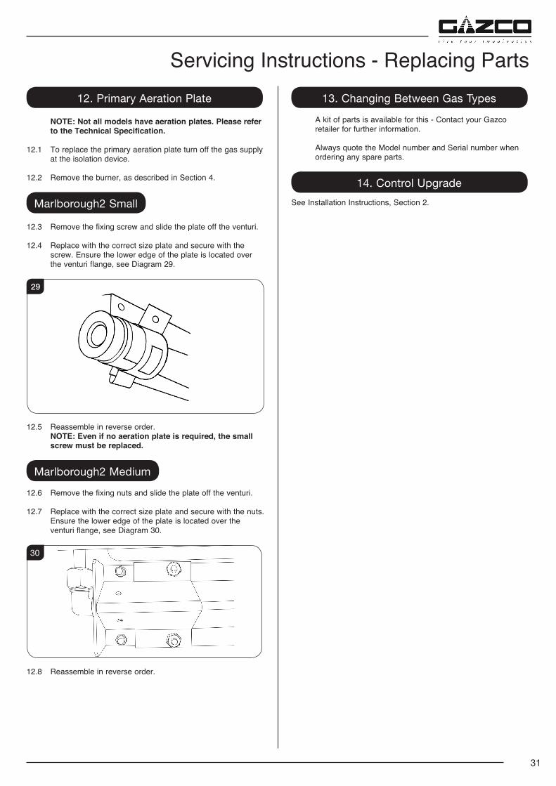
Servicing Instructions - Replacing Parts12. Primary Aeration Plate
NOTE: Not all models have aeration plates. Please refer to the Technical Specification.
12.1 To replace the primary aeration plate turn off the gas supply at the isolation device.
12.2 Remove the burner, as described in Section 4.
Marlborough2 Small
12.3 Remove the fixing screw and slide the plate off the venturi.
12.4 Replace with the correct size plate and secure with the screw. Ensure the lower edge of the plate is located over the venturi flange, see Diagram 29.
29
12.5 Reassemble in reverse order. NOTE: Even if no aeration plate is required, the small
screw must be replaced.
Marlborough2 Medium
12.6 Remove the fixing nuts and slide the plate off the venturi.
12.7 Replace with the correct size plate and secure with the nuts. Ensure the lower edge of the plate is located over the venturi flange, see Diagram 30.
30
12.8 Reassemble in reverse order.
13. Changing Between Gas Types
A kit of parts is available for this - Contact your Gazco retailer for further information.
Always quote the Model number and Serial number when ordering any spare parts.
14. Control UpgradeSee Installation Instructions, Section 2.
32
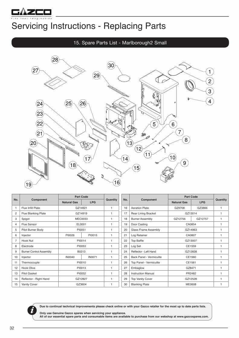
Servicing Instructions - Replacing Parts15. Spare Parts List - Marlborough2 Small
No. ComponentPart Code
QuantityNatural Gas LPG
1 Flue Infill Plate GZ14921 1
2 Flue Blanking Plate GZ14919 1
3 Spigot MEC0033 1
4 Flue Sensor EL0001 1
5 Pilot Burner Body PI0051 1
6 Injector PI0026 PI0015 1
7 Hook Nut PI0014 1
8 Electrode PI0053 1
9 Burner Control Assembly B0213 1
10 Injector IN0040 IN0071 1
11 Thermocouple PI0010 1
12 Hook Olive PI0013 1
13 Pilot Gasket PI0052 1
14 Reflector - Right Hand GZ12827 1
15 Vanity Cover GZ3604 1
Due to continual technical improvements please check online or with your Gazco retailer for the most up to date parts lists.
Only use Genuine Gazco spares when servicing your appliance. All of our essential spare parts and consumable items are available to purchase from our webshop at www.gazcospares.com.
No. ComponentPart Code
QuantityNatural Gas LPG
16 Aeration Plate GZ9708 GZ3866 1
17 Rear Lining Bracket GZ13014 1
18 Burner Assembly GZ12756 GZ12757 1
19 Door Casting CA0854 1
20 Glass Frame Assembly GZ14963 1
21 Log Retainer CA0807 1
22 Top Baffle GZ13007 1
23 Log Set CE1559 1
24 Reflector - Left Hand GZ12828 1
25 Back Panel - Vermiculite CE1560 1
26 Top Panel - Vermiculite CE1561 1
27 Embaglow GZ8471 1
28 Instruction Manual PR2482 1
29 Top Vanity Cover GZ12528 1
30 Blanking Plate ME0608 1
33
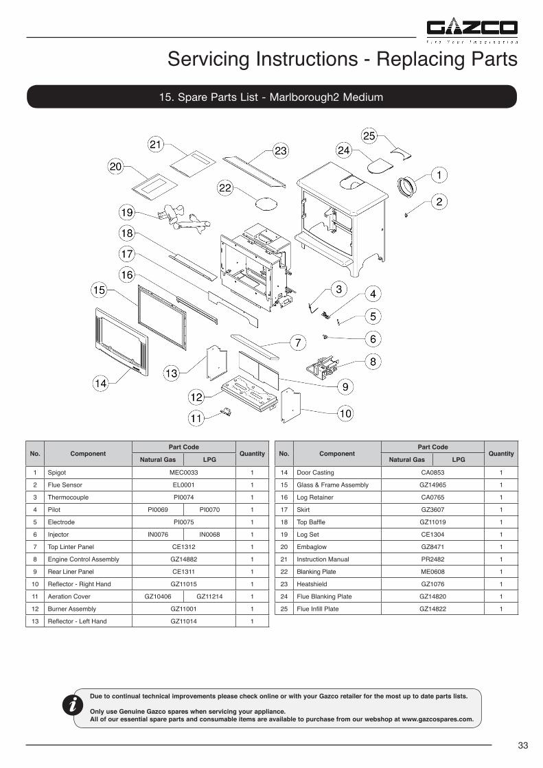
Servicing Instructions - Replacing Parts15. Spare Parts List - Marlborough2 Medium
Due to continual technical improvements please check online or with your Gazco retailer for the most up to date parts lists.
Only use Genuine Gazco spares when servicing your appliance. All of our essential spare parts and consumable items are available to purchase from our webshop at www.gazcospares.com.
No. ComponentPart Code
QuantityNatural Gas LPG
1 Spigot MEC0033 1
2 Flue Sensor EL0001 1
3 Thermocouple PI0074 1
4 Pilot PI0069 PI0070 1
5 Electrode PI0075 1
6 Injector IN0076 IN0068 1
7 Top Linter Panel CE1312 1
8 Engine Control Assembly GZ14882 1
9 Rear Liner Panel CE1311 1
10 Reflector - Right Hand GZ11015 1
11 Aeration Cover GZ10406 GZ11214 1
12 Burner Assembly GZ11001 1
13 Reflector - Left Hand GZ11014 1
No. ComponentPart Code
QuantityNatural Gas LPG
14 Door Casting CA0853 1
15 Glass & Frame Assembly GZ14965 1
16 Log Retainer CA0765 1
17 Skirt GZ3607 1
18 Top Baffle GZ11019 1
19 Log Set CE1304 1
20 Embaglow GZ8471 1
21 Instruction Manual PR2482 1
22 Blanking Plate ME0608 1
23 Heatshield GZ1076 1
24 Flue Blanking Plate GZ14820 1
25 Flue Infill Plate GZ14822 1
34
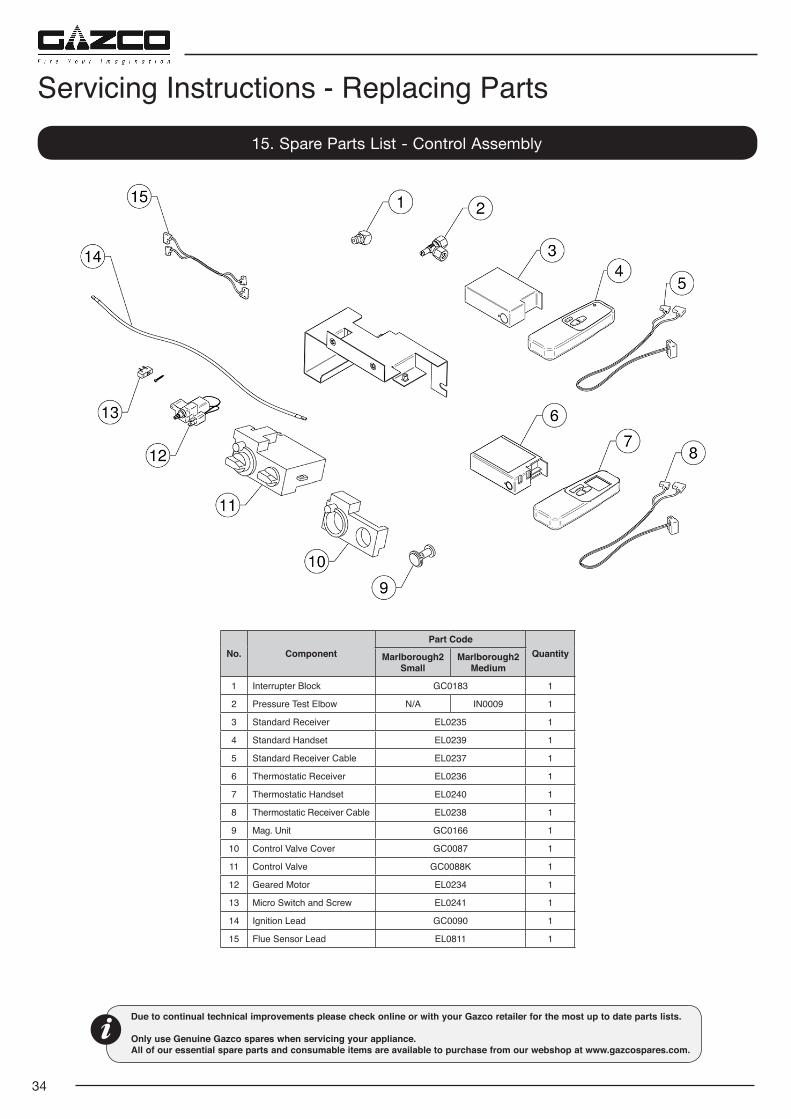
Servicing Instructions - Replacing Parts15. Spare Parts List - Control Assembly
Due to continual technical improvements please check online or with your Gazco retailer for the most up to date parts lists.
Only use Genuine Gazco spares when servicing your appliance. All of our essential spare parts and consumable items are available to purchase from our webshop at www.gazcospares.com.
No. ComponentPart Code
QuantityMarlborough2 Small
Marlborough2 Medium
1 Interrupter Block GC0183 1
2 Pressure Test Elbow N/A IN0009 1
3 Standard Receiver EL0235 1
4 Standard Handset EL0239 1
5 Standard Receiver Cable EL0237 1
6 Thermostatic Receiver EL0236 1
7 Thermostatic Handset EL0240 1
8 Thermostatic Receiver Cable EL0238 1
9 Mag. Unit GC0166 1
10 Control Valve Cover GC0087 1
11 Control Valve GC0088K 1
12 Geared Motor EL0234 1
13 Micro Switch and Screw EL0241 1
14 Ignition Lead GC0090 1
15 Flue Sensor Lead EL0811 1
35
1ST SERVICE
Date of Service .........................................................................
Next Service Due ......................................................................
Signed .......................................................................................
Retailer's Stamp/GasSafe Registration Number
3RD SERVICE
Date of Service .........................................................................
Next Service Due ......................................................................
Signed .......................................................................................
Retailer's Stamp/GasSafe Registration Number
5TH SERVICE
Date of Service .........................................................................
Next Service Due ......................................................................
Signed .......................................................................................
Retailer's Stamp/GasSafe Registration Number
7TH SERVICE
Date of Service .........................................................................
Next Service Due ......................................................................
Signed .......................................................................................
Retailer's Stamp/GasSafe Registration Number
9TH SERVICE
Date of Service .........................................................................
Next Service Due ......................................................................
Signed .......................................................................................
Retailer's Stamp/GasSafe Registration Number
2ND SERVICE
Date of Service .......................................................................
Next Service Due ....................................................................
Signed .....................................................................................
Retailer's Stamp/GasSafe Registration Number
4TH SERVICE
Date of Service .......................................................................
Next Service Due ....................................................................
Signed .....................................................................................
Retailer's Stamp/GasSafe Registration Number
6TH SERVICE
Date of Service .......................................................................
Next Service Due ....................................................................
Signed .....................................................................................
Retailer's Stamp/GasSafe Registration Number
8TH SERVICE
Date of Service .......................................................................
Next Due .................................................................................
Signed .....................................................................................
Retailer's Stamp/GasSafe Registration Number
10TH SERVICE
Date of Service .......................................................................
Next Service Due ....................................................................
Signed .....................................................................................
Retailer's Stamp/GasSafe Registration Number
Service Records
36
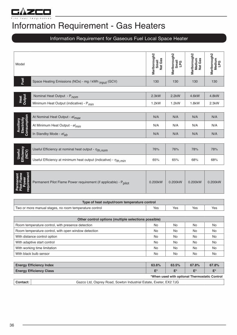
Model
Mar
lbor
ough
2 Sm
all
Nat
Gas
Mar
lbor
ough
2 Sm
all
LPG
Mar
lbor
ough
2 M
ediu
mN
at G
as
Mar
lbor
ough
2 M
ediu
mLP
G
Fuel Space Heating Emissions (NOx) - mg / kWh input (GCV) 130 130 130 130
Hea
tO
utpu
t Nominal Heat Output - Pnom 2.3kW 2.2kW 4.6kW 4.8kW
Minimum Heat Output (indicative) - Pmin 1.2kW 1.2kW 1.8kW 2.3kW
Aux
iliar
y El
ectr
icity
C
onsu
mpt
ion At Nominal Heat Output - elmax N/A N/A N/A N/A
At Minimum Heat Output - elmin N/A N/A N/A N/A
In Standby Mode - elsb N/A N/A N/A N/A
Use
ful
Effic
ienc
y (N
CV)
Useful Efficiency at nominal heat output - ηth,nom 76% 76% 78% 78%
Useful Efficiency at minimum heat output (indicative) - ηth,min 65% 65% 68% 68%
Perm
anen
t Pi
lot F
lam
e Po
wer
re
quire
men
t
Permanent Pilot Flame Power requirement (if applicable) - Ppilot 0.200kW 0.200kW 0.200kW 0.200kW
Type of heat output/room temperature controlTwo or more manual stages, no room temperature control Yes Yes Yes Yes
Other control options (multiple selections possible)Room temperature control, with presence detection No No No NoRoom temperature control, with open window detection No No No NoWith distance control option No No No NoWith adaptive start control No No No NoWith working time limitation No No No NoWith black bulb sensor No No No No
Energy Efficiency Index 63.6% 63.5% 67.8% 67.8%Energy Efficiency Class E* E* E* E*
*When used with optional Thermostatic ControlContact: Gazco Ltd, Osprey Road, Sowton Industrial Estate, Exeter, EX2 7JG
Information Requirement for Gaseous Fuel Local Space Heater
Information Requirement - Gas Heaters


Gazco Limited, Osprey Road, Sowton Industrial Estate, Exeter, Devon, England EX2 7JGTechnical Customer Services: (01392) 261950 Fax: (01392) 261951
E-mail: [email protected] member of the Stovax Group
E & O E